Andrew Wireless Innovations Group RPT-MR303V-24 Repeater User Manual M0041A8B
Andrew Wireless Innovations Group Repeater M0041A8B
UserManual.wiki
>
Andrew Wireless Innovations Group
>
RPT-MR303V-24 User Manual
>
Manual
Contents
1.
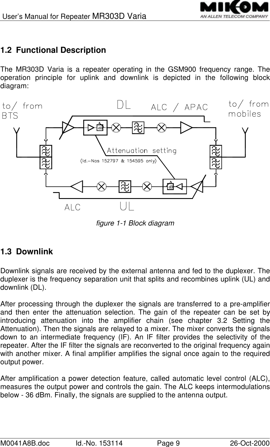
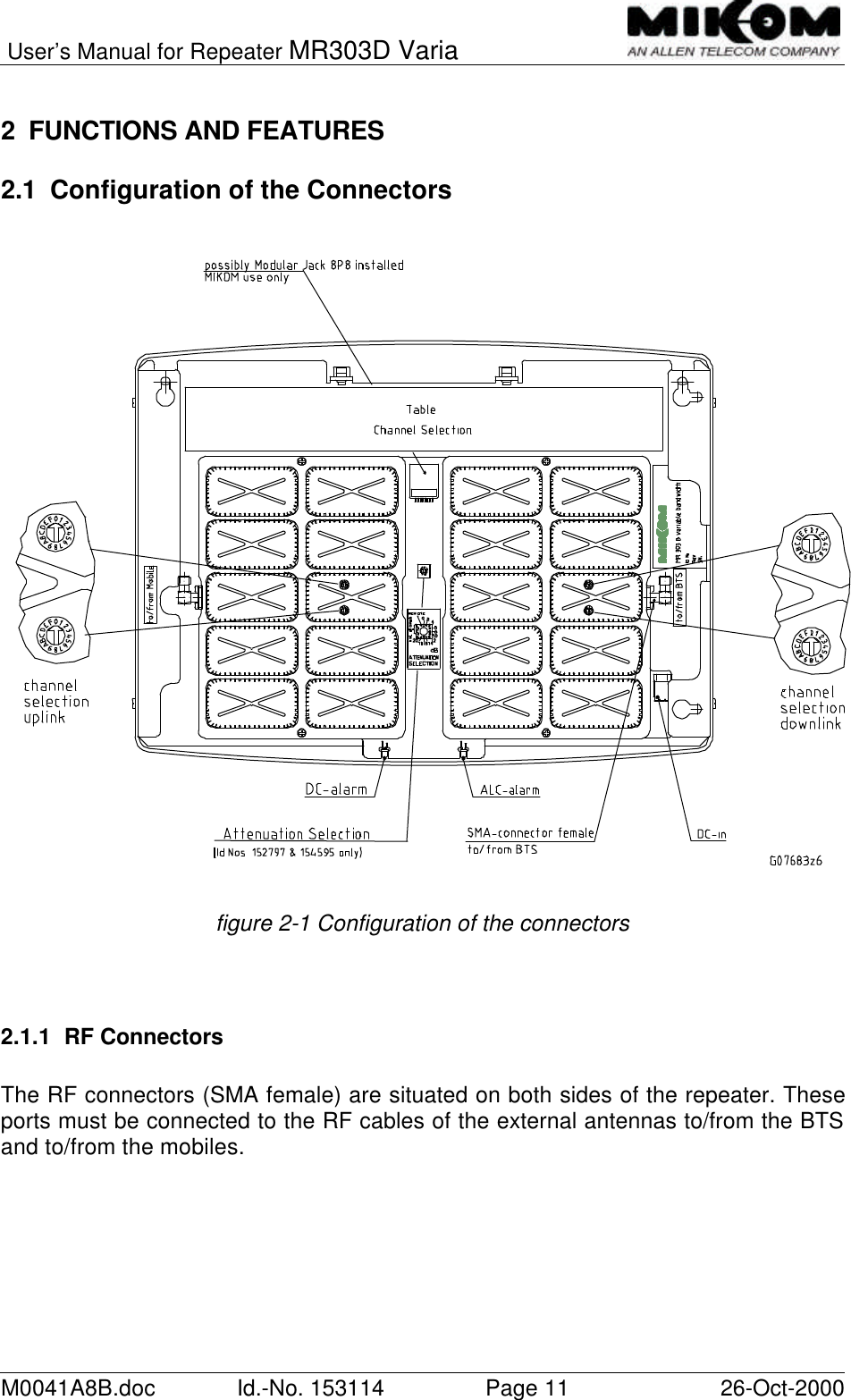
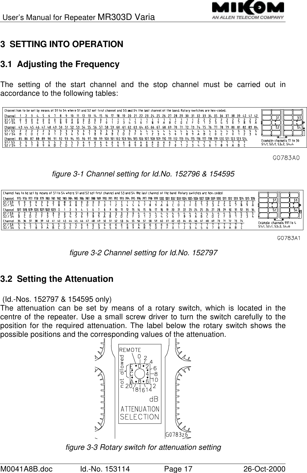
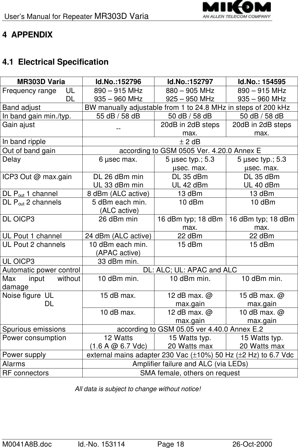
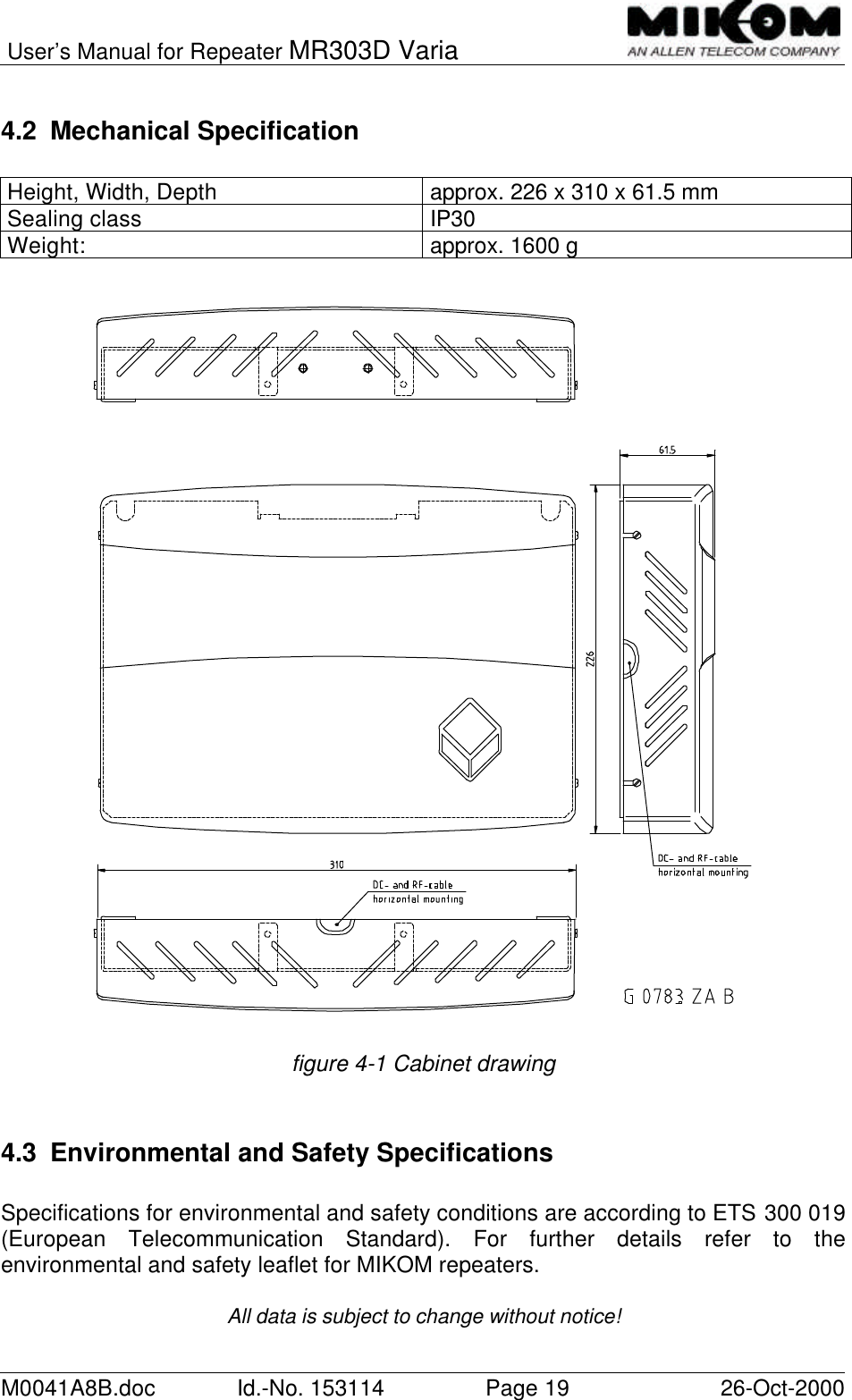
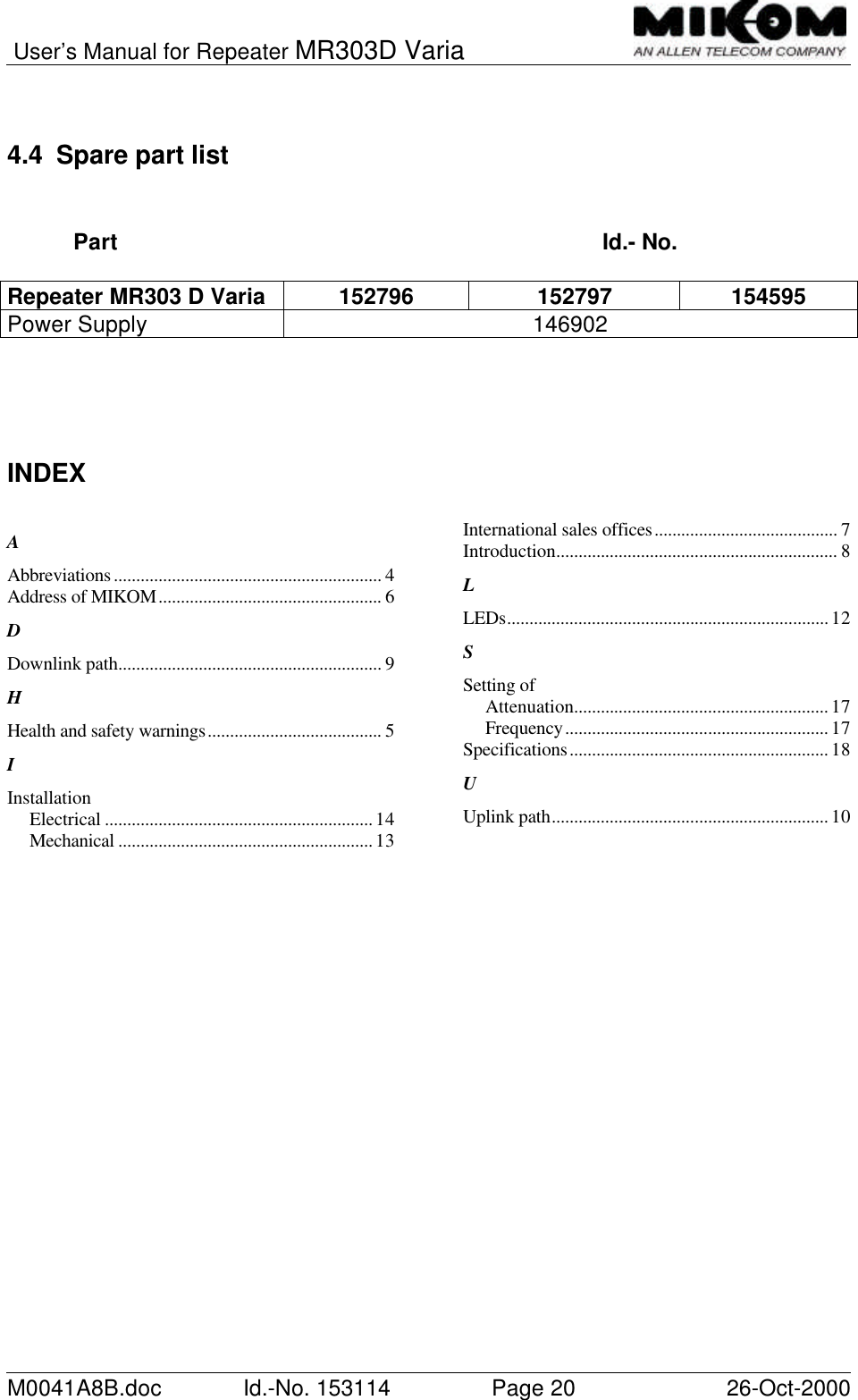
Manual
2.
Manual addendum
Manual
Navigation menu
Upload a User Manual
Namespaces
Wiki Guide
HTML
PDF
Info
Views
User Manual
Discussion / Help
Navigation