Andrew Wireless Innovations Group RPT-MR703 Bi-Directional Amplifier for Small Area Indoor Coverage User Manual M0041A3A
Andrew Wireless Innovations Group Bi-Directional Amplifier for Small Area Indoor Coverage M0041A3A
Contents
- 1. User Manual
- 2. Appendix to user manual
- 3. Update to manual
User Manual
M0041A3A.doc Id.-No. 149678 22-Jan-99
User's guide MR703
models A, B and D
Installation and setting to work
The electrical installation has to be performed in
accordance with the safety regulations of the local
authorities. Due to safety reasons the electrical
installation must be performed by qualified
personnel only. The Repeater must not be opened !
Mechanical installation
The mechanical installation has to be done according
to the attached wall mounting sheet. Mount the Unit
horizontally only. Otherwise the radiation pattern of
the internal antenna is not optimised.
Configuration of the LEDs and connectors
First of all the difference between the models
A, B and D is given. The difference between models A
and B is simply the different gain whereas model D
provides an additional duplexer for the connection of
an antenna to/from the mobiles. That means that the
model D has got an additional RF port at the opposite
side to the RF port to/from the BTS. A block diagram
of both models (A,B and D) is given on the next page.
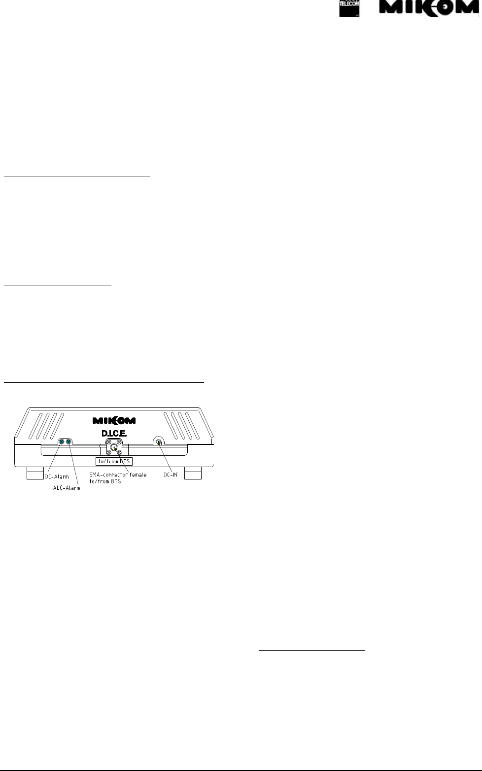
The following explanation is made with respect to the
figure shown above. The RF connector (SMA female)
is situated in the middle of the Repeater. This port has
to be connected to the RF cable of the antenna to/from
the BTS.
The socket for the DC supply is situated to the right of
the RF connector. Power supply voltage is 6.7 Vdc,
current is 1.2 A typ.
You have two possibilities to provide the MR703 with
power.
The first one is to use an external power supply and
connect it to the DC socket of the Repeater and the
other one is to bias the MR703 via the cable to the RF
port to/from BTS. If you use an external power supply
use only the power supply that was shipped with the
unit. If you want to bias the MR703 make sure that the
correct voltage is fed into the MR703. Furthermore the
DC socket of the MR703 must not be connected if the
bias via RF cable is carried out.
The indication of the LEDs is as follows: The LED on
the left hand side (DC alarm) can show green light or
red light. A green LED indicates the normal operation
of the Repeater. It shows that power is present and that
the current consumption of the Unit is correct. A red
indication of this LED means that the current
consumption of the Repeater is not within a defined
window and that the Repeater thus might not work
properly. If the LED is switched off the MR703 doesn't
get DC power at all.
The LED next to this LED is the ALC/APAC alarm
LED. If this LED is on it indicates that the input
power into the Repeater is too high, so that the output
power of the Repeater has to be limited. This can be
either the UL ALC or APAC or the DL ALC! This
limitation ensures that the final stage is not overdriven
and that intermodulations are kept below the CEPT
limits
(- 30 dBm).
The RF port that is only implemented in the model D
has to be connected to the external antenna that
establishes the communication with the mobile
phones.
Electrical specification
The electrical specification can be found on a separate
sheet on which the values of the final measurments are
noted.
MIKOM GmbH * Industriering 10 * 86675 Buchdorf * Germany
Tel. {+49} 9099-690 * Fax {+49} 9099-6931
email: sales@mikom.com * http://www.mikom.com
Functional Description
The MR703 is a Repeater operating in the PCS1900 frequency range. The operation principle is given with
regard to the following block diagrams.
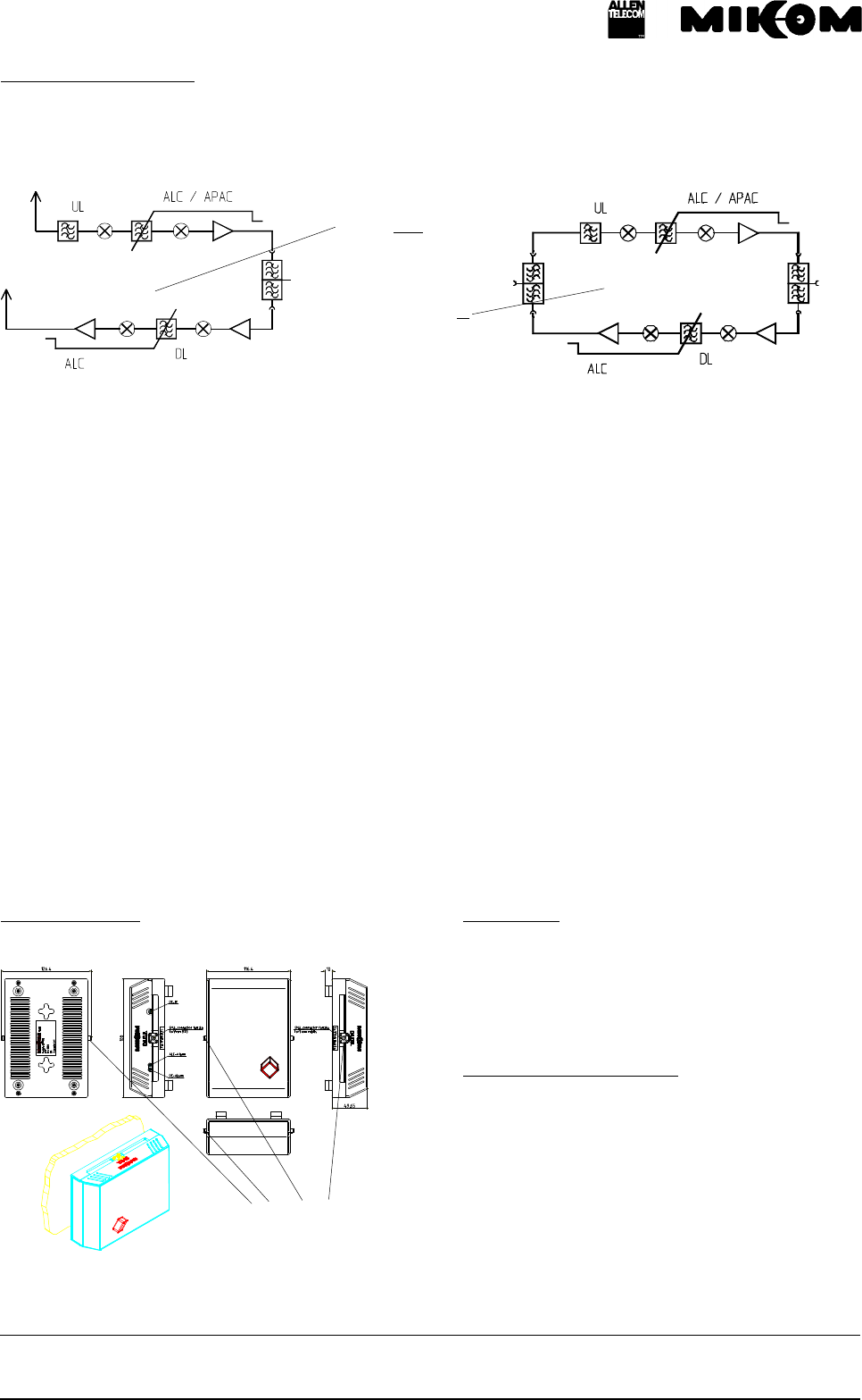
MR703A/B
MR703D
Downlink signals reach the duplexer. The duplexer is the frequency separation unit that splits and recombines
uplink (UL) and downlink (DL).
After the duplexer the signals get to a pre-amplifier and afterwards to a mixer. The mixer converts the signals
down to an intermediate frequency (IF). An IF filter provides the selectivity of the Repeater. After the IF filter the
signals are reconverted to the original frequency again by means of another mixer. A final amplifier amplifies the
signal again and provides the required output power.
After the final amplifier a power detection measures the output power and controls the gain. This is called
automatic gain control (ALC) and keeps intermodulations below - 30 dBm. Finally, the signals are fed to the
built-in antenna of the Repeater (MR703A/B) or the duplexer and thus to the external antenna (MR703D).
The uplink signals are received by the integrated antenna of the Repeater (MR703A/B) or the external antenna
and then to the duplexer (MR703D). After the antenna or duplexer a preselection of the frequency is made. After
that the signals are converted down to IF by means of a mixer and an IF filter provides the selectivity against
other frequencies. After the reconversion the signals are amplified in an amplifier that provides the output power.
The signals are then fed to the antenna via the duplexer.
In this link an ALC and an automatic power adjust circuit (APAC) is provided. APAC limits the output power if
two carriers are present at the UL input. This again keeps intermodulations below the desired limit.
Cabinet drawing
only in model D
Mechanical
Dimensions:
(W x H x D) approx. 166 x 120 x 60 mm
Weight: approx. 550 g
Environmental and safety
The specifications for environmental and safety are
according to ETS 300 019 (European Tele-
communication Standard). For further details please
ask your supplier for a leaflet.
All data is subject to change without notice !