Andrew Wireless Innovations Group RPT-MR703 Bi-Directional Amplifier for Small Area Indoor Coverage User Manual M0041A3A
Andrew Wireless Innovations Group Bi-Directional Amplifier for Small Area Indoor Coverage M0041A3A
Contents
- 1. User Manual
- 2. Appendix to user manual
- 3. Update to manual
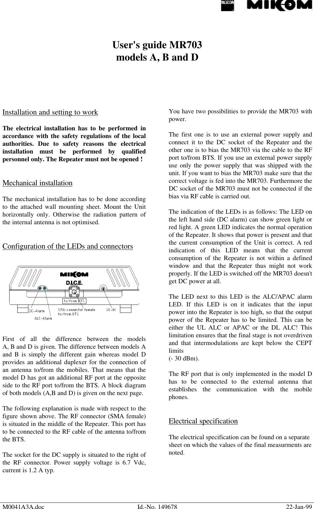
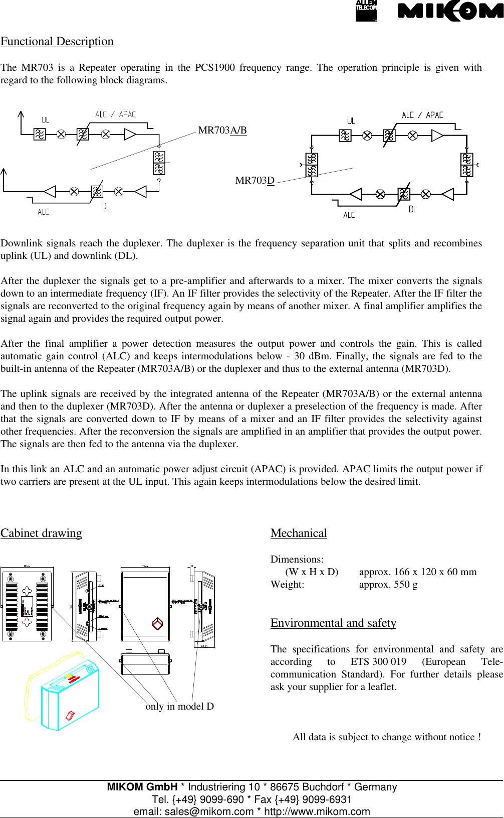
User Manual