Andrew Wireless Innovations Group RPT-MR803P-TR SMR Repeater User Manual User sManual
Andrew Wireless Innovations Group SMR Repeater User sManual
UserManual.wiki
>
Andrew Wireless Innovations Group
>
RPT MR803P TR User Manual
Users Manual
Navigation menu
Upload a User Manual
Namespaces
Wiki Guide
HTML
PDF
Info
Views
User Manual
Discussion / Help
Navigation
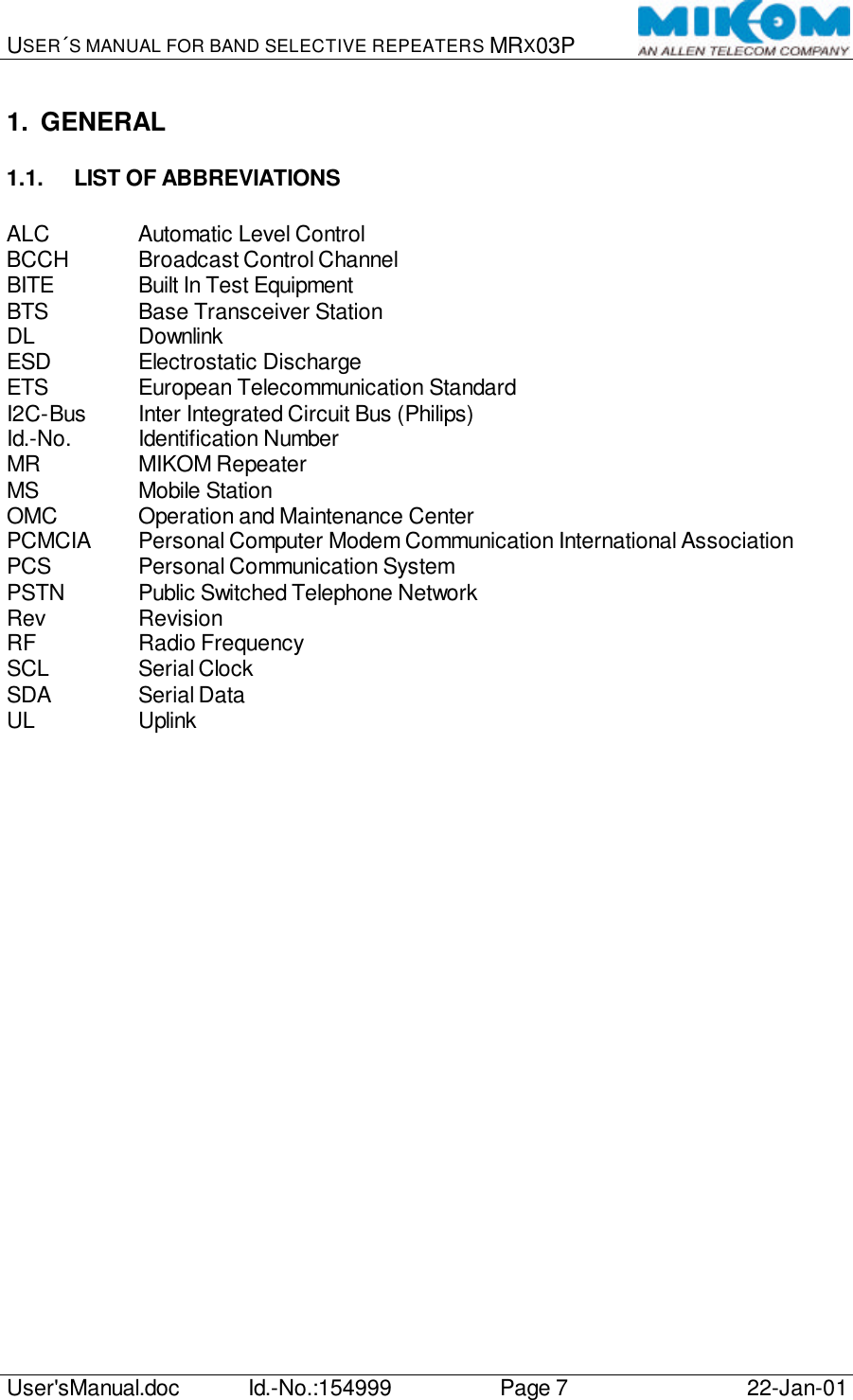
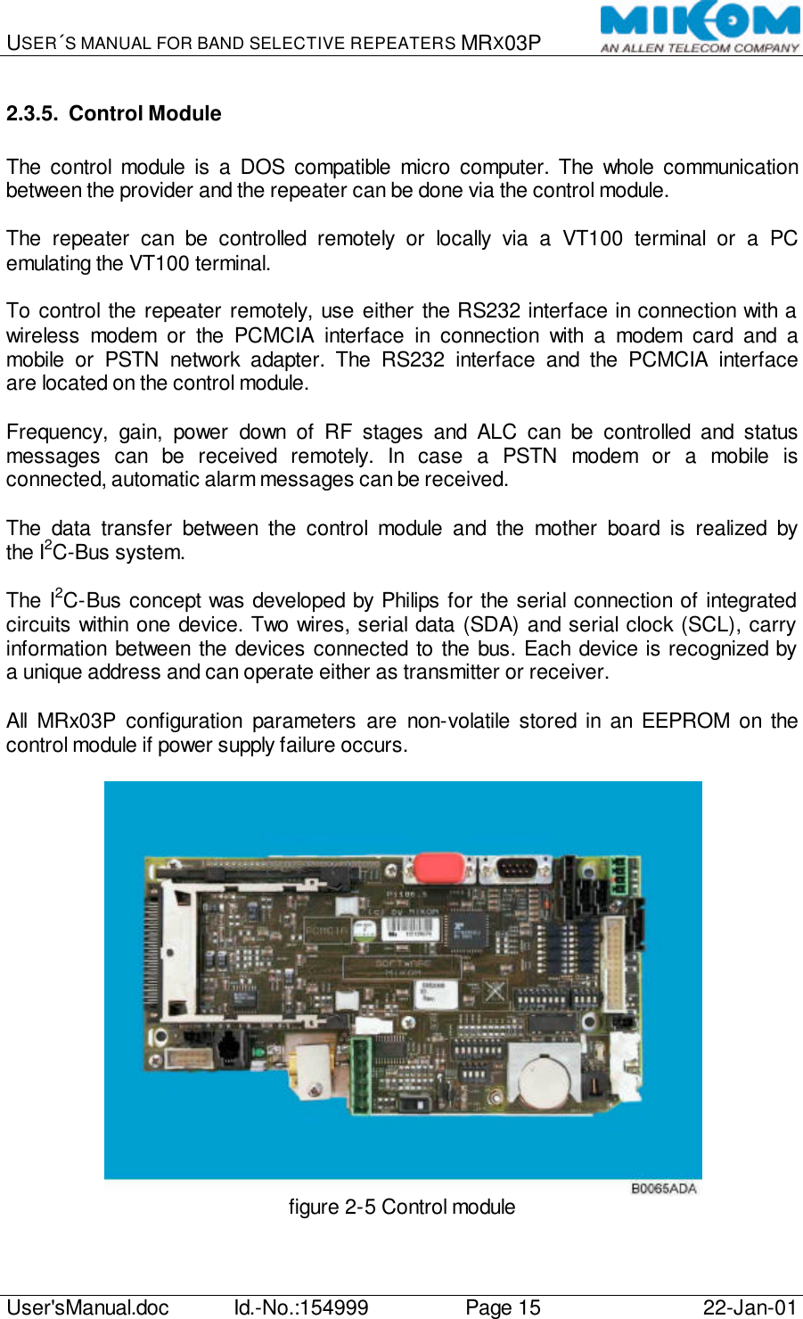
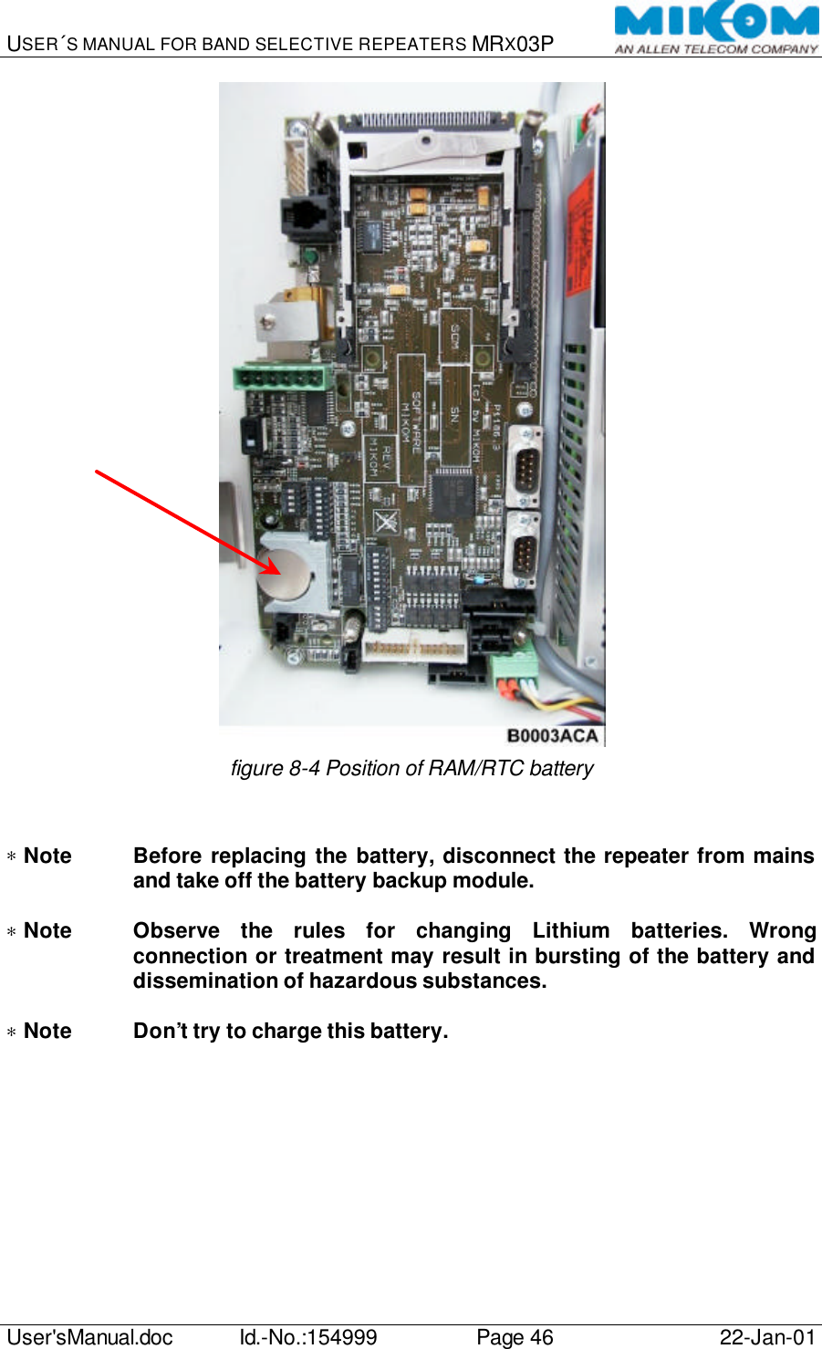
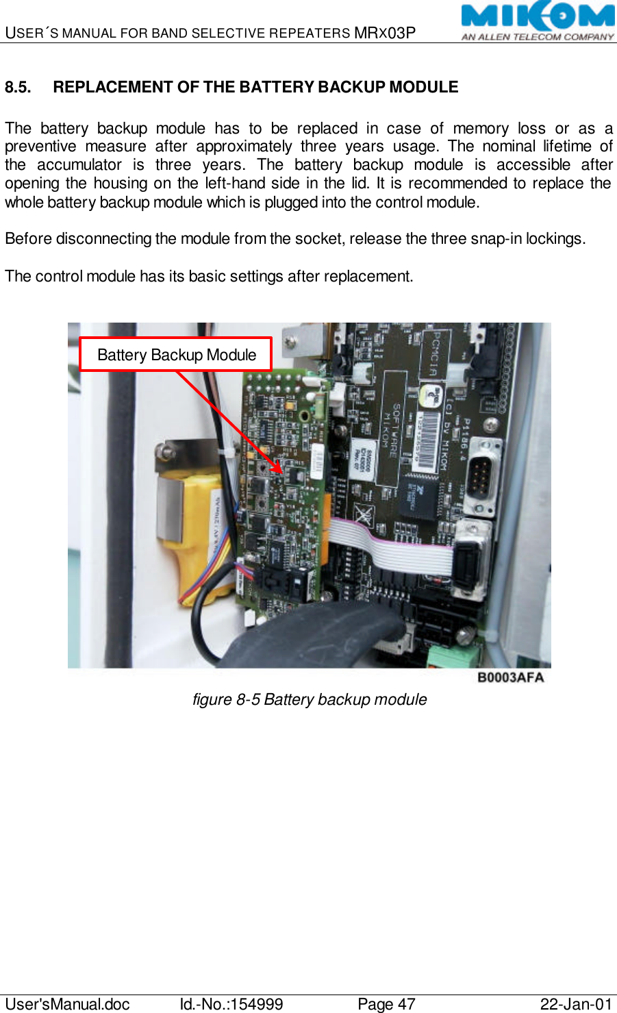
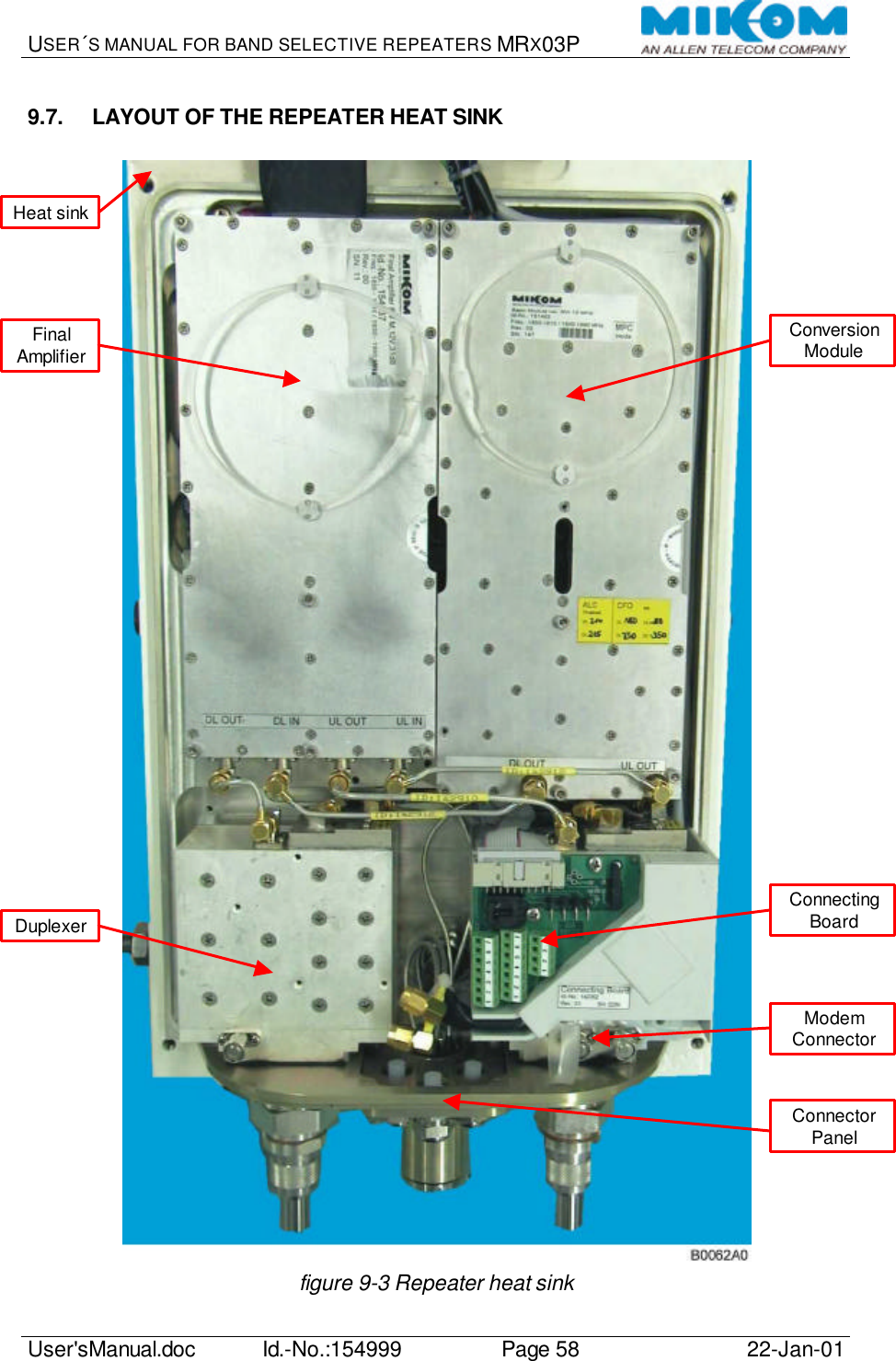
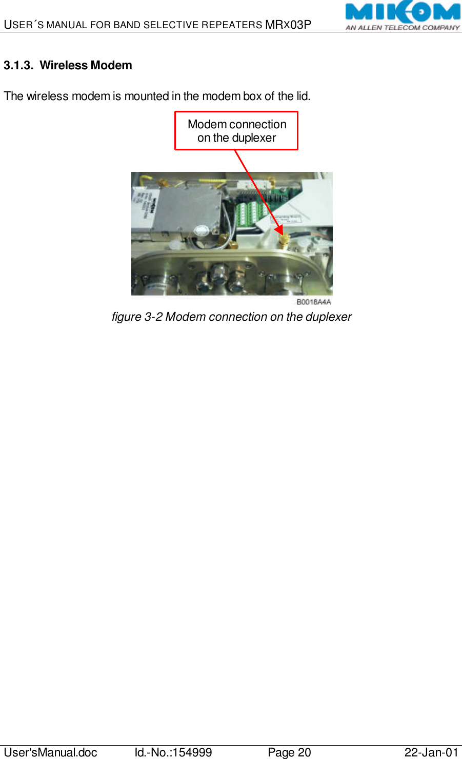
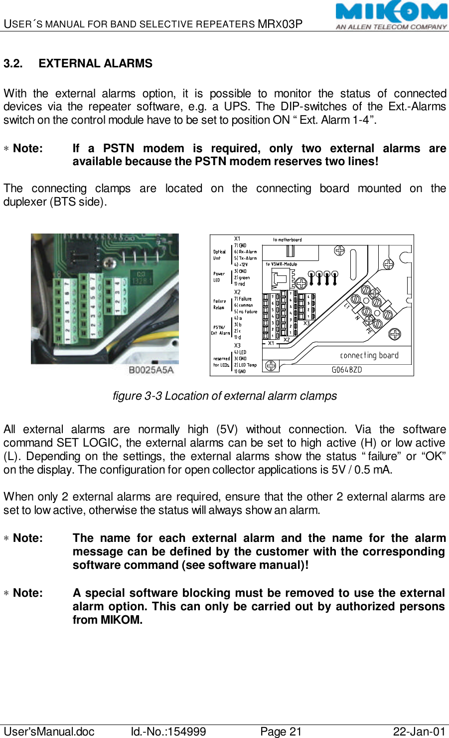
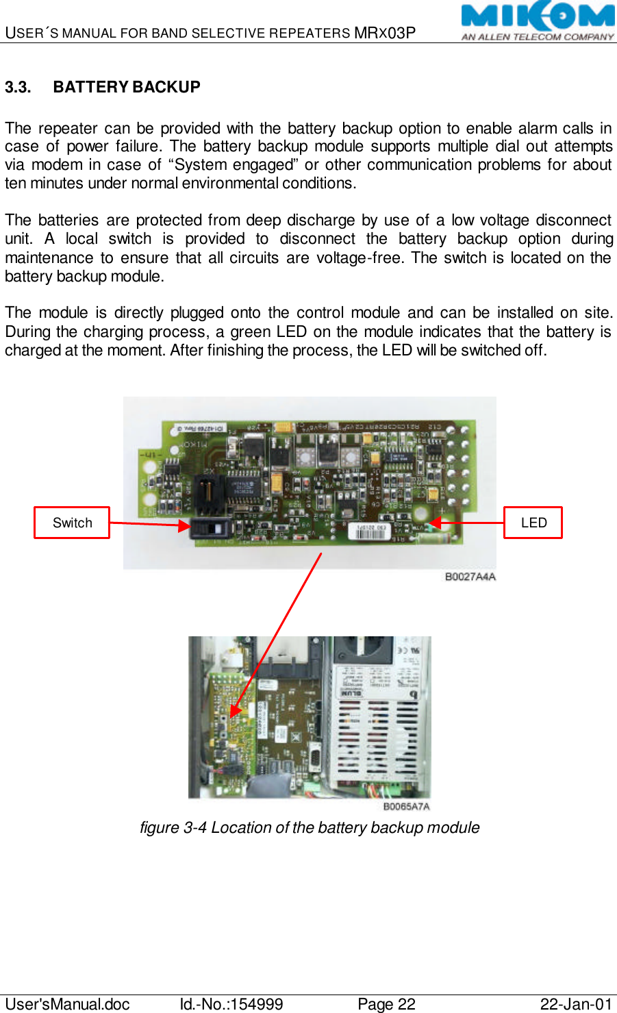
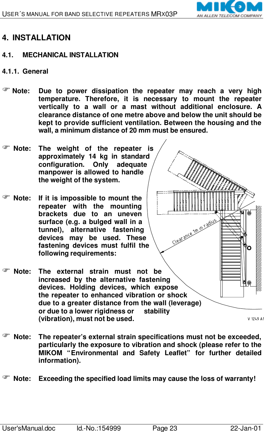
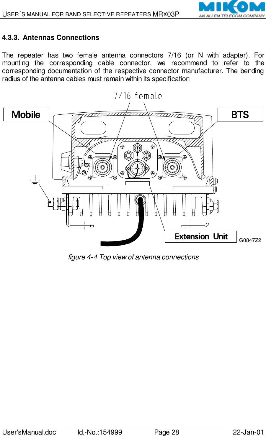
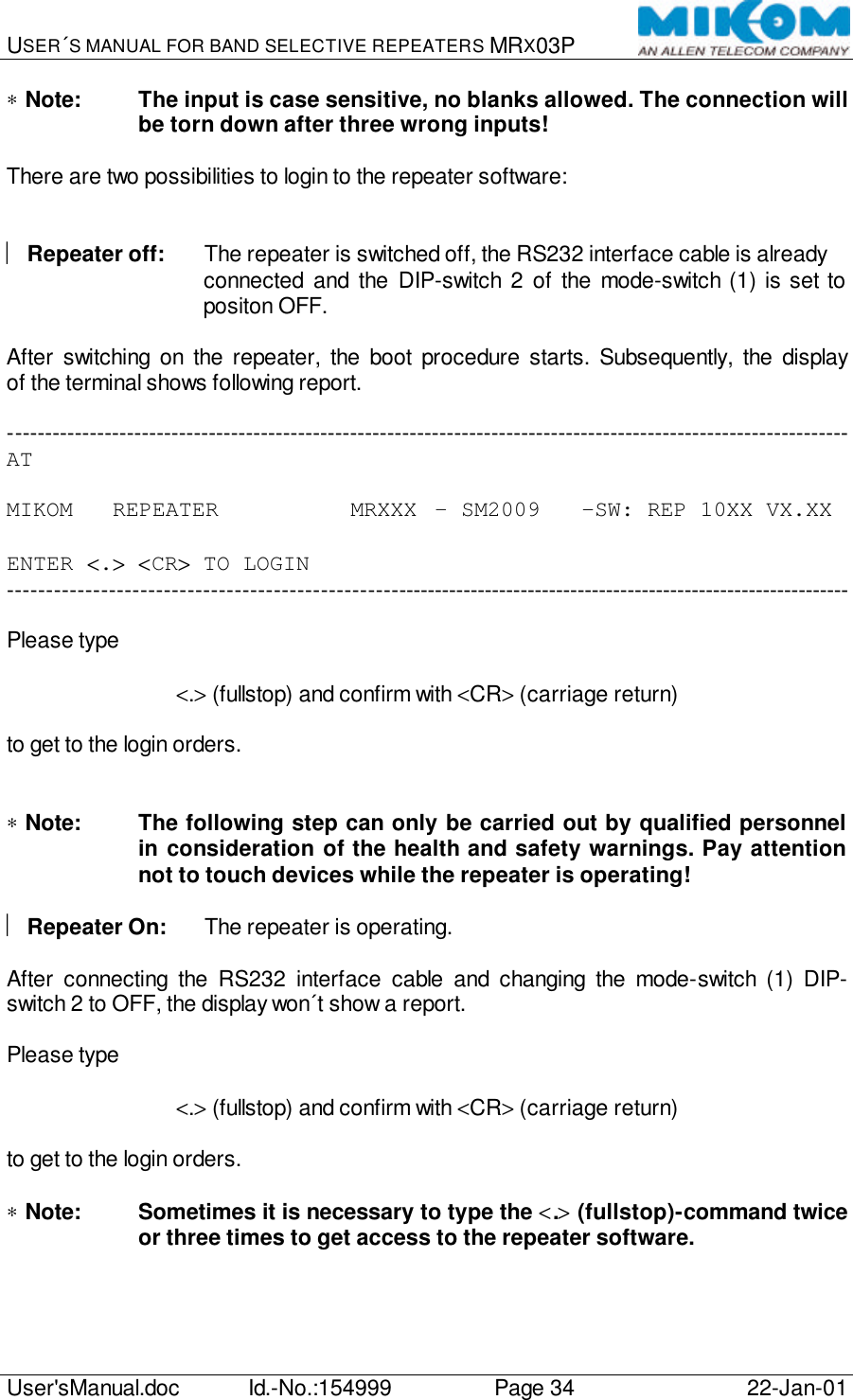
![USER´S MANUAL FOR BAND SELECTIVE REPEATERS MRX03P User'sManual.doc Id.-No.:154999 Page 19 22-Jan-01 3.1.2. PSTN Modem A Hayes compatible PSTN modem can be connected to the control module SM2009. The telephone cable has to be fed through a labeled grommet of the connector panel and must be connected to the designated clamps. For the standard modem type DigiTel 56Euro, use clamps 2 and 3 to connect the telephone lines a and b. Previous standard modems type DigiTel 34P use clamps 1 and 4. In case of failure try both possibilities to check the functionality of the modem connection. figure 3-1 Location of the PSTN Modem ∗ Note: If a PSTN modem is required, the DIP-switches of the Ext. Alarms-switch [4] on the control module has to be set to position OFF “PSTN Modem”. The DIP-switch 2 of the Mode-switch [1] has to be set to position ON “Remote Mode”.](https://usermanual.wiki/Andrew-Wireless-Innovations-Group/RPT-MR803P-TR/User-Guide-300193-Page-19.png)
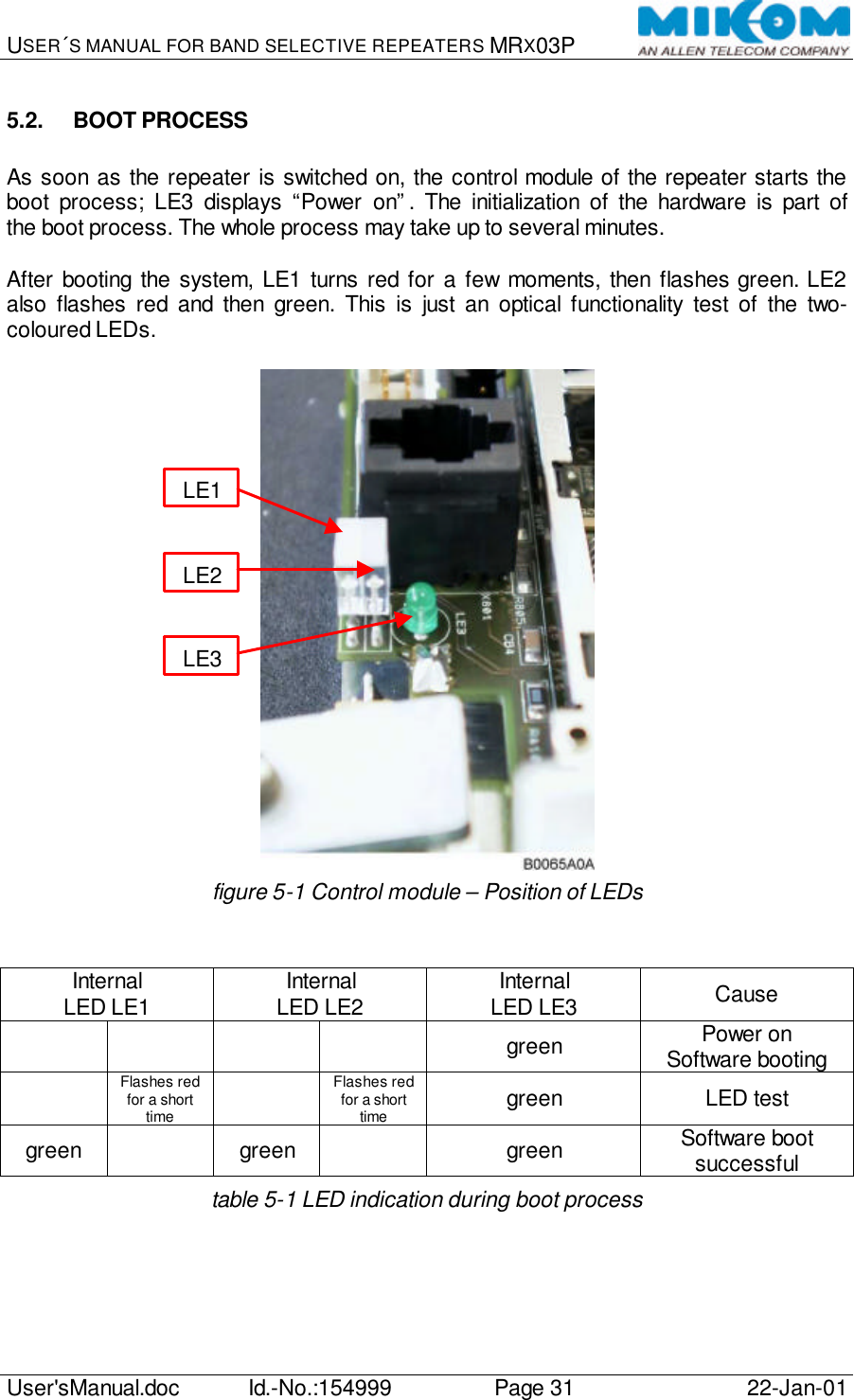
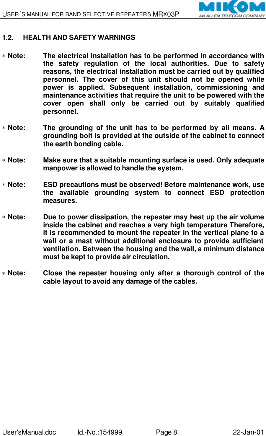
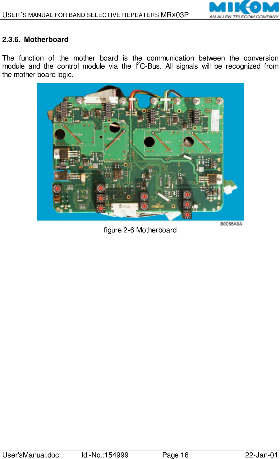
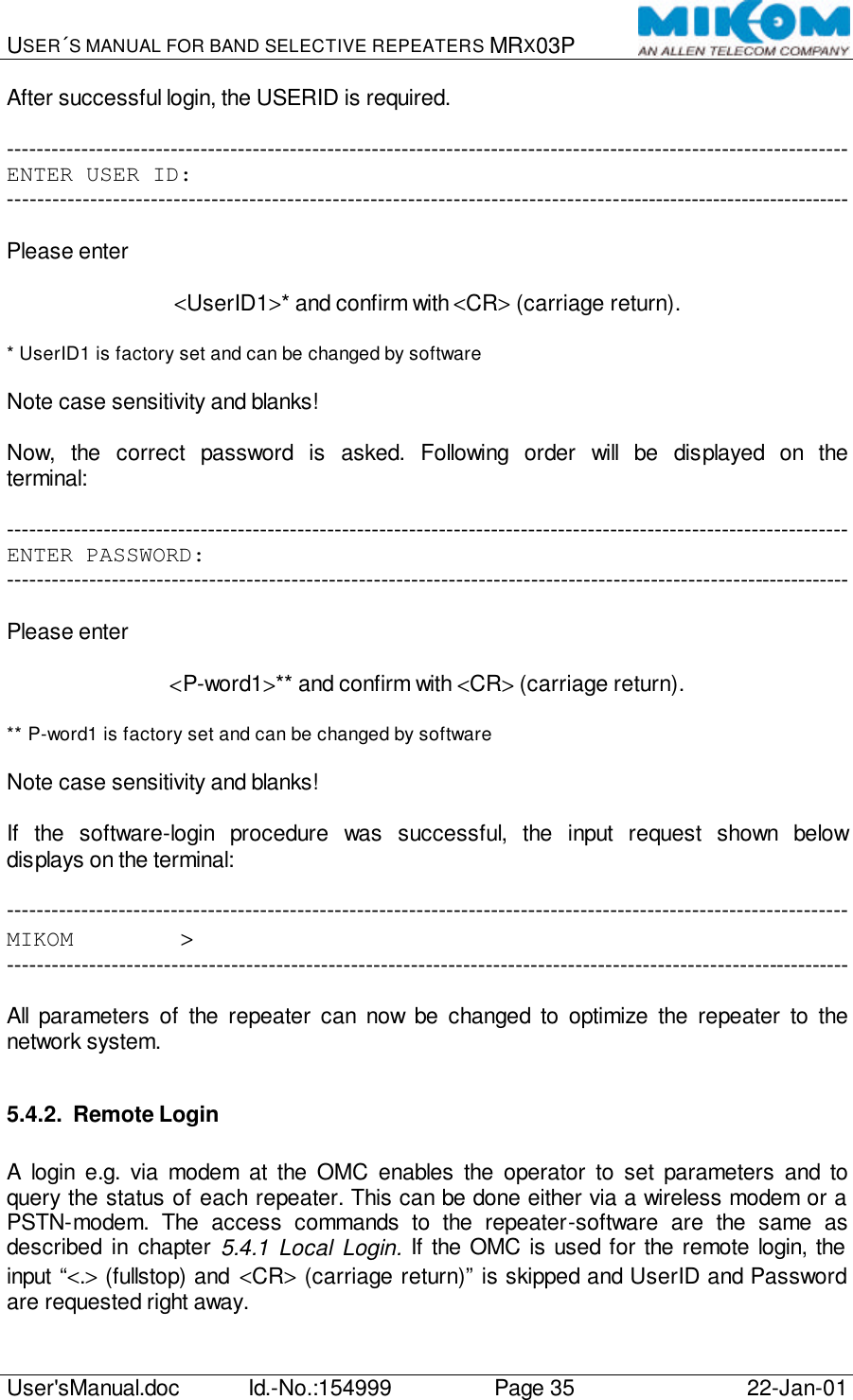
![USER´S MANUAL FOR BAND SELECTIVE REPEATERS MRX03P User'sManual.doc Id.-No.:154999 Page 32 22-Jan-01 5.3. DIP-SWITCHES The configuration of the DIP-switches on the control module is factory set. figure 5-2 Control module – Position of the DIP-switches Mode-switch [1]* Ext. Alarms-switch [4] ON OFF ON OFF 1 Manual Auto 1 Ext. Alarm 4 PSTN (d) 2 Remote Mode Local Mode 2 Ext. Alarm 3 PSTN (c) 3 DO NOT USE! DO NOT USE! 3 Ext. Alarm 2 PSTN (b) 4 DO NOT USE! Auto 4 Ext. Alarm 1 PSTN (a) Switch for additional inputs [2]** MOR/MR-switch [3] ON OFF ON OFF 1 VCC O.C. 1 MR MOR 2 VCC O.C. 2 MR MOR 3 VCC O.C. 3 MR MOR 4 VCC O.C. 4 MR MOR 5 VCC O.C. 5 MOR MR 6 VCC O.C. 6 MOR MR 7 VCC O.C. 7 MOR MR 8 VCC O.C. 8 MOR MR * Switch 1, 3 and 4 are factory set to position Off ** Switch for additional inputs not in use! table 5-2 DIP-switches of control module 1234](https://usermanual.wiki/Andrew-Wireless-Innovations-Group/RPT-MR803P-TR/User-Guide-300193-Page-32.png)
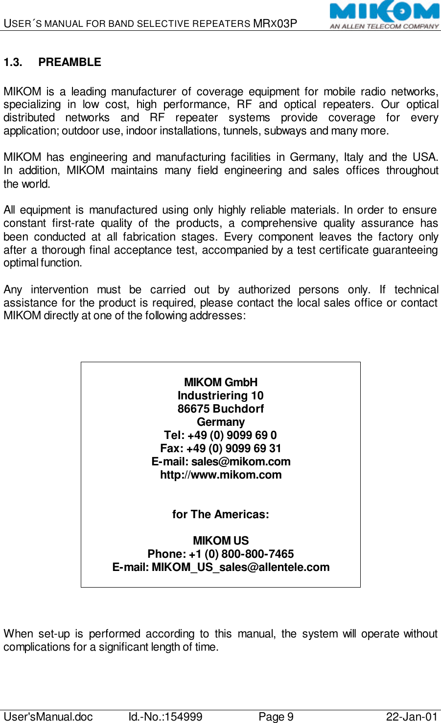
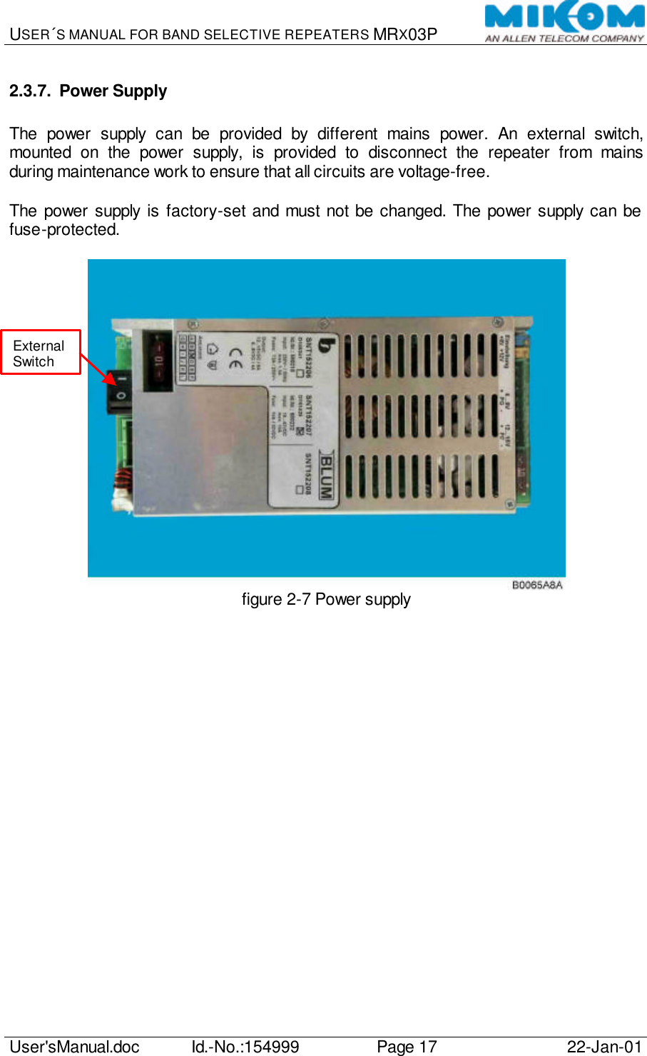
![USER´S MANUAL FOR BAND SELECTIVE REPEATERS MRX03P User'sManual.doc Id.-No.:154999 Page 33 22-Jan-01 5.4. REMOTE SETTINGS After the boot process, the software login is possible. All parameters of the software can be changed by the provider to optimize the repeater according to the network system. There are two possibilities how to login to the software: ∫ locally via a VT100 terminal or a PC with VT100 terminal emulation ∫ remotely via a modem e.g. with the Operations and Maintenance Center (OMC) 5.4.1. Local Login The login via VT100 terminal or a PC with VT100 emulation can only be performed at the repeater. Open the repeater carefully and ensure that DIP-switch 2 of mode-switch [1] is in position OFF. Only when DIP-switch 2 is OFF, a local access to the software on the control module is possible (see chapter 5.3 DIP-Switches). Connect the terminal or PC to the RS232 interface on the control module by means of a standard RS232 interface cable (see picture below). Terminal or PC Control Module SM2009 9 contact SUB-D-connector 9 contact SUB-D-connector male male Pin Pin 123456789897613452 Check the communication mode at the terminal. If necessary, set the following parameters: Bit rate / bit per second: 9600 baud Number of data bit: 8 bit Parity bit: No parity Stopbit: 1 stopbit](https://usermanual.wiki/Andrew-Wireless-Innovations-Group/RPT-MR803P-TR/User-Guide-300193-Page-33.png)
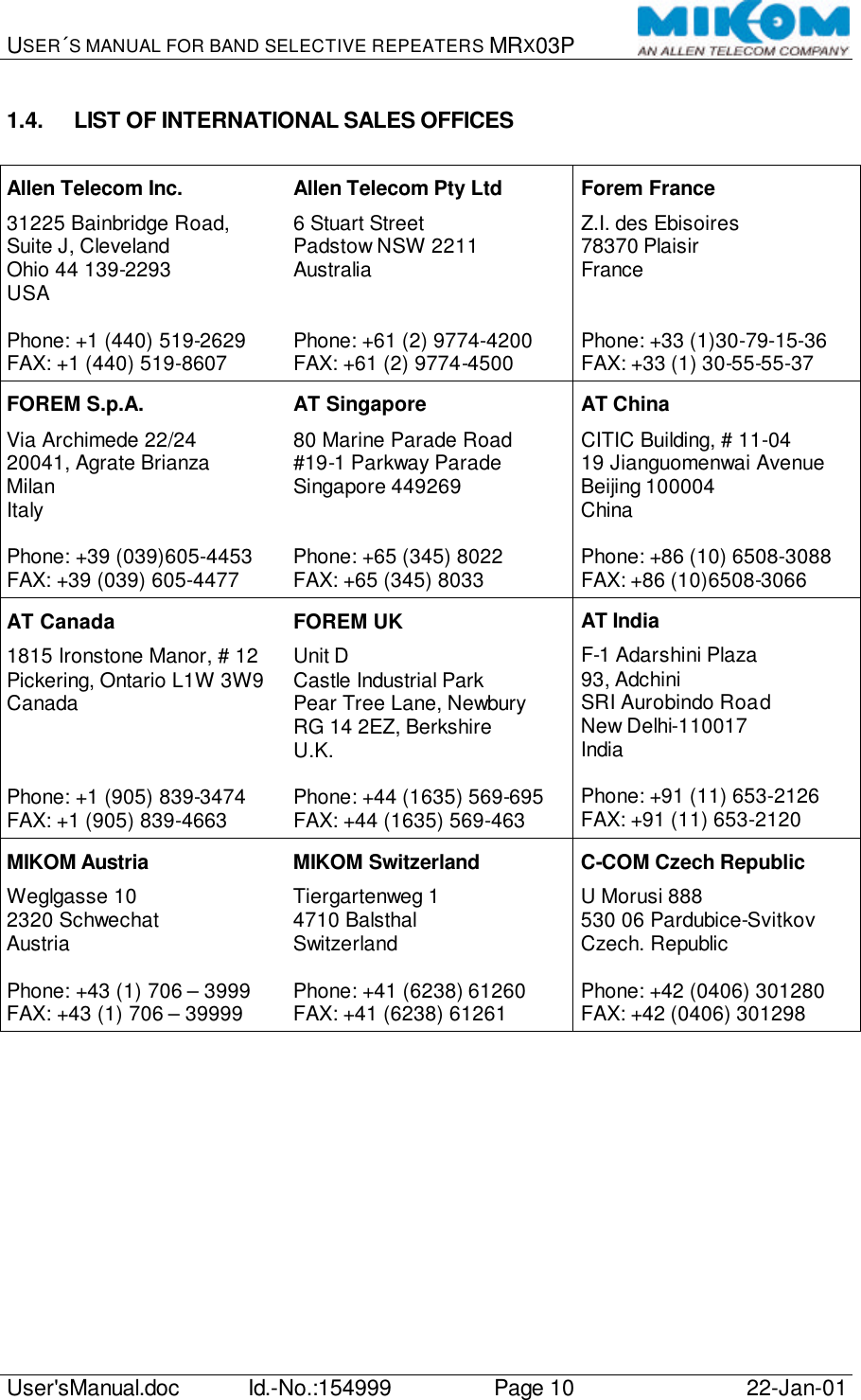
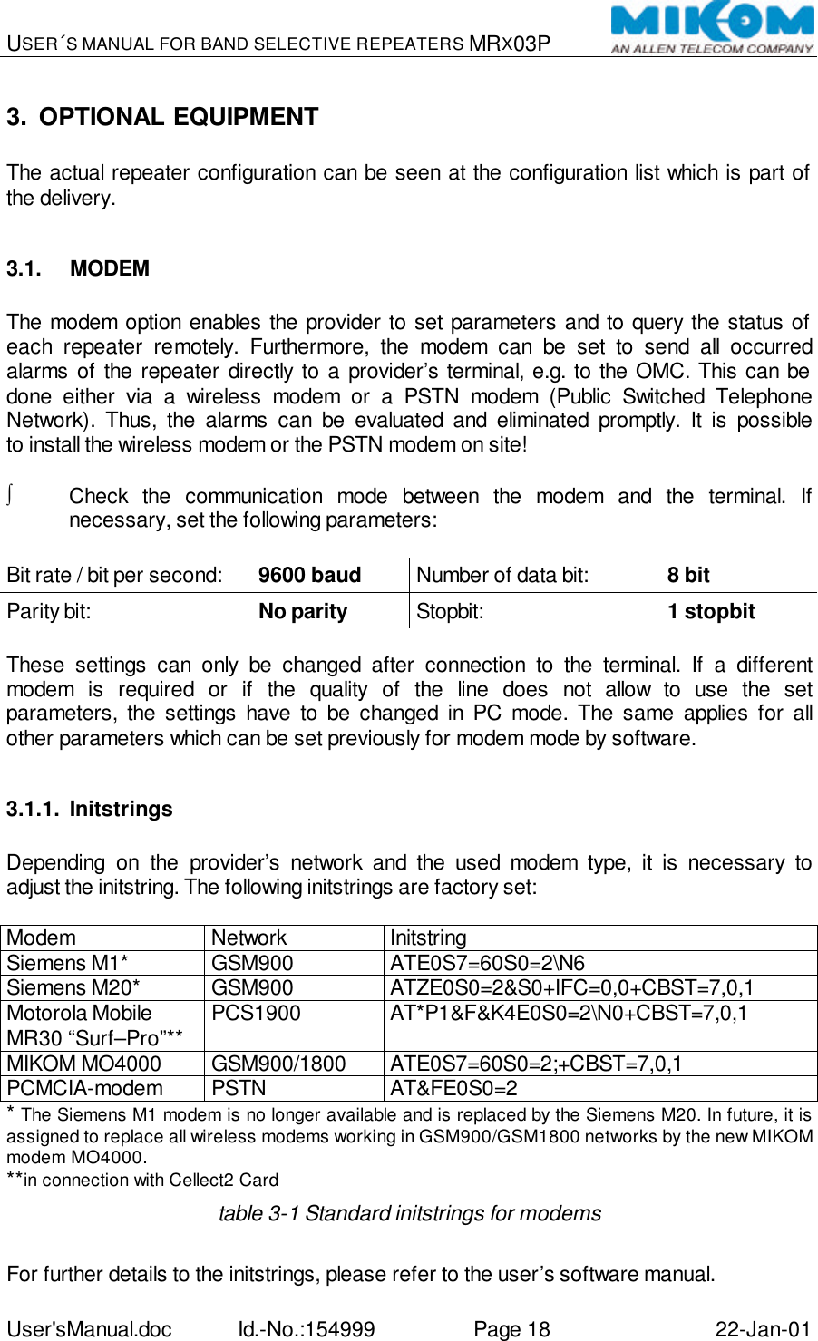
![USER´S MANUAL FOR BAND SELECTIVE REPEATERS MRX03P User'sManual.doc Id.-No.:154999 Page 36 22-Jan-01 For further details to software-login and software-commands, please refer to the user´s software. 5.5. MANUAL SETTINGS Normally, settings are carried out by a VT100 terminal or PC. Additionally, if manual settings are unavoidable, rotary switches on the motherboard enables the operator to optimize the gain and to set the channels. To enable the manual setting of attenuation and channels, ensure that the DIP-switch 1 of the mode switch [1] is in position ON (manual mode). An attenuation of 30 dB max. in steps of 2 dB can be set in the UL- and DL path for channel and band selective repeaters. The channel settings are only available for channel selective repeaters. ∗ Note: While DIP-switch 1 of mode switch (1) is in position ON (manual mode), software settings via VT100 terminal are not possible! Quering the status can still be carried out. figure 5-3 Motherboard Example: Position 0 of the rotary switches S7/S8 equals 0 dB attenuation. Position 1 attenuates the signal by 2 dB, position 8 for instance attenuates by 16 dB. To achieve max. attenuation (30dB), turn the rotary switch of the corresponding path to position F. S4 S5 S6 S7 S8 S9 S1 S2 S3](https://usermanual.wiki/Andrew-Wireless-Innovations-Group/RPT-MR803P-TR/User-Guide-300193-Page-36.png)
![USER´S MANUAL FOR BAND SELECTIVE REPEATERS MRX03P User'sManual.doc Id.-No.:154999 Page 37 22-Jan-01 The following table and the example show how to use the rotary-switches*: Switch Description S1 Channel code x100 S2 Channel code x10 S3 Channel code x1 S4 Channel code x100 S5 Channel code x10 S6 Channel code x1 S7 Attenuation in 2 dB steps upto 30 dB for UL-path S8 Attenuation in 2 dB steps upto 30 dB for DL-path S9 Code switch for motherboard * Factory settings are: S1-S8 in position 0, DIP-switch 1 of mode switch [1] in position “Off” (Automatic mode). Switch S9 can be set to position 0 to 3 depending on the location of the motherboard in the repeater. table 5-3 Rotary switches of the motherboard Example: A gain of 74 dB is required in the UL- and DL-path, module 1 is set to channel 96 and module 2 to channel 113. The repeater has a gain of max. 82 dB. 1. Calculate the difference between the max. repeater gain and the required gain. Max. repeater gain: 82 dB Required gain for UL and DL: 74 dB ------------- Required attenuation for UL and DL: 8 dB 2. Turn switch S7 as well as S8 to position 4 to set an attenuation of 8 dB for UL- and DL-path. 3. Set channel 96 for module 1: Turn switch S1 to position 0: 0 Turn switch S2 to position 9: 90 Turn switch S3 to position 6: 6 -------- Channel: 96 4. Set channel 113 for module 2: Turn switch S4 to position 1: 100 Turn switch S5 to position 1: 10 Turn switch S6 to position 3: 3 -------- Channel: 113](https://usermanual.wiki/Andrew-Wireless-Innovations-Group/RPT-MR803P-TR/User-Guide-300193-Page-37.png)