Andrew Wireless Innovations Group RPT-MR803P-TR SMR Repeater User Manual User sManual
Andrew Wireless Innovations Group SMR Repeater User sManual
Users Manual
USER´S MANUAL FOR BAND SELECTIVE REPEATERS MRX03P
User'sManual.doc Id.-No.:154999 Page 1 22-Jan-01
User´s manual for
band selective repeater
MRx03P

USER´S MANUAL FOR BAND SELECTIVE REPEATERS MRX03P
User'sManual.doc Id.-No.:154999 Page 2 22-Jan-01
Copyright MIKOM, Buchdorf 2001
All rights reserved.
No parts of this publication may be reproduced,
stored in a retrieval system, transmitted in any form or by any means,
electronical, mechanical photocopying, recording or otherwise,
without prior written permission of the publisher.

USER´S MANUAL FOR BAND SELECTIVE REPEATERS MRX03P
User'sManual.doc Id.-No.:154999 Page 3 22-Jan-01
TABLE OF CONTENTS
1. GENERAL 7
1.1. LIST OF ABBREVIATIONS 7
1.2. HEALTH AND SAFETY WARNINGS 8
1.3. PREAMBLE 9
1.4. LIST OF INTERNATIONAL SALES OFFICES 10
2. FUNCTIONAL DESCRIPTION 11
2.1. GENERAL 11
2.2. REPEATER DESIGN 11
2.3. COMPONENTS OF THE MRX03P 12
2.3.1. Duplexer 12
2.3.2. Measuring Aids 12
2.3.3. Conversion Module 13
2.3.4. Final Amplifier 14
2.3.5. Control Module 15
2.3.6. Motherboard 16
2.3.7. Power Supply 17
3. OPTIONAL EQUIPMENT 18
3.1. MODEM 18
3.1.1. Initstrings 18
3.1.2. PSTN Modem 19
3.1.3. Wireless Modem 20
3.2. EXTERNAL ALARMS 21
3.3. BATTERY BACKUP 22
4. INSTALLATION 23
4.1. MECHANICAL INSTALLATION 23
4.1.1. General 23
4.2. WALL MOUNTING PROCEDURE 24
4.2.1. Pole Mounting Procedure 25
4.3. ELECTRICAL INSTALLATION 27
4.3.1. Grounding 27
4.3.2. Mains Power Supply 27
4.3.3. Antennas Connections 28

USER´S MANUAL FOR BAND SELECTIVE REPEATERS MRX03P
User'sManual.doc Id.-No.:154999 Page 4 22-Jan-01
5. COMMISSIONING 29
5.1. PREPARATION 29
5.1.1. General 29
5.1.2. BCCH-Channel 29
5.1.3. Antenna Isolation 30
5.2. BOOT PROCESS 31
5.3. DIP-SWITCHES 32
5.4. REMOTE SETTINGS 33
5.4.1. Local Login 33
5.4.2. Remote Login 35
5.5. MANUAL SETTINGS 36
5.6. LEVELLING OF THE REPEATER 38
6. ALARMS 39
6.1. BITE AND ALARMS 39
6.2. HANDLING OF ALARMS 39
6.3. STATUS REPORT 39
7. TROUBLE SHOOTING 40
7.1. ERROR INDICATION 40
7.2. BOOT PROCESS 41
7.3. ALARM MONITORING WITH THE ALARM HISTORY 41
7.4. POWER SUPPLY 41
7.5. GENERAL REMARKS 42
8. MAINTENANCE 43
8.1. GENERAL 43
8.2. REPLACEMENT OF THE FUSES 44
8.3. REPLACEMENT OF THE MAINS CABLE 44
8.4. REPLACEMENT OF THE RAM / RTC BATTERY 45
8.5. REPLACEMENT OF THE BATTERY BACKUP MODULE 47
8.6. DUPLEXER 48

USER´S MANUAL FOR BAND SELECTIVE REPEATERS MRX03P
User'sManual.doc Id.-No.:154999 Page 5 22-Jan-01
8.7. CONVERSION MODULE 48
8.8. CONTROL MODULE SM 2009 49
8.9. POWER SUPPLY 49
8.10. CONNECTING BOARD 50
9. APPENDIX 51
9.1. ELECTRICAL SPECIFICATIONS 51
9.1.1. Specifications of MR703P 51
9.1.2. Specifications of MR803P 52
9.2. MECHANICAL SPECIFICATION 53
9.3. ENVIRONMENTAL AND SAFETY SPECIFICATIONS 53
9.4. SPARE PARTS LISTS 54
9.4.1. Spare Parts List of MR703P 54
9.4.2. Spare Parts List of MR803P 55
9.5. INSTALLATION DRAWING OF THE REPEATER 56
9.6. LAYOUT OF THE REPEATER LID 57
9.7. LAYOUT OF THE REPEATER HEAT SINK 58
10. INDEX 59

USER´S MANUAL FOR BAND SELECTIVE REPEATERS MRX03P
User'sManual.doc Id.-No.:154999 Page 6 22-Jan-01
LIST OF FIGURES AND TABLES
figure 2-1 Configuration of a MRx03P ...................................................................................11
figure 2-2 Duplexer.....................................................................................................................12
figure 2-3 Conversion module .................................................................................................13
figure 2-4 Final amplifier ...........................................................................................................14
figure 2-5 Control module .........................................................................................................15
figure 2-6 Motherboard..............................................................................................................16
figure 2-7 Power supply ............................................................................................................17
figure 1-1 Location of the PSTN Modem...............................................................................19
figure 1-2 Modem connection on the duplexer ....................................................................20
figure 3-3 Location of external alarm clamps.......................................................................21
figure 3-4 Location of the battery backup module...............................................................22
figure 4-1 Installation drawings of a repeater.......................................................................24
figure 4-2 MIKOM pole mounting kits. ...................................................................................25
figure 4-3 Grounding bolt ..........................................................................................................27
figure 4-4 Top view of antenna connections ........................................................................28
figure 5-1 Control module – Position of LEDs......................................................................31
figure 5-2 Control module – Position of the DIP-switches.................................................32
figure 5-3 Motherboard..............................................................................................................36
figure 8-1 Fuse replacement....................................................................................................44
figure 8-2 Connecting board ....................................................................................................44
figure 8-3 Cable gland ...............................................................................................................45
figure 8-4 Position of RAM/RTC battery................................................................................46
figure 8-5 Battery backup module...........................................................................................47
figure 8-6 Connecting board ....................................................................................................50
figure 9-1 Installation drawing of MRx03P............................................................................56
figure 9-2 Repeater lid...............................................................................................................57
figure 9-3 Repeater heat sink ..................................................................................................58
table 1-1 Standard initstrings for modems............................................................................18
table 5-1 LED indication during boot process......................................................................31
table 5-2 DIP-switches of control module .............................................................................32
table 5-3 Rotary switches of the motherboard.....................................................................37
table 9-1 Specification of MR703P .........................................................................................51
table 9-2 Specification of MR803P .........................................................................................52
table 9-3 Spare parts list of MR703P.....................................................................................54
table 9-4 Spare parts list of MR803P.....................................................................................55

USER´S MANUAL FOR BAND SELECTIVE REPEATERS MRX03P
User'sManual.doc Id.-No.:154999 Page 7 22-Jan-01
1. GENERAL
1.1. LIST OF ABBREVIATIONS
ALC Automatic Level Control
BCCH Broadcast Control Channel
BITE Built In Test Equipment
BTS Base Transceiver Station
DL Downlink
ESD Electrostatic Discharge
ETS European Telecommunication Standard
I2C-Bus Inter Integrated Circuit Bus (Philips)
Id.-No. Identification Number
MR MIKOM Repeater
MS Mobile Station
OMC Operation and Maintenance Center
PCMCIA Personal Computer Modem Communication International Association
PCS Personal Communication System
PSTN Public Switched Telephone Network
Rev Revision
RF Radio Frequency
SCL Serial Clock
SDA Serial Data
UL Uplink

USER´S MANUAL FOR BAND SELECTIVE REPEATERS MRX03P
User'sManual.doc Id.-No.:154999 Page 8 22-Jan-01
1.2. HEALTH AND SAFETY WARNINGS
∗ Note: The electrical installation has to be performed in accordance with
the safety regulation of the local authorities. Due to safety
reasons, the electrical installation must be carried out by qualified
personnel. The cover of this unit should not be opened while
power is applied. Subsequent installation, commissioning and
maintenance activities that require the unit to be powered with the
cover open shall only be carried out by suitably qualified
personnel.
∗ Note: The grounding of the unit has to be performed by all means. A
grounding bolt is provided at the outside of the cabinet to connect
the earth bonding cable.
∗ Note: Make sure that a suitable mounting surface is used. Only adequate
manpower is allowed to handle the system.
∗ Note: ESD precautions must be observed! Before maintenance work, use
the available grounding system to connect ESD protection
measures.
∗ Note: Due to power dissipation, the repeater may heat up the air volume
inside the cabinet and reaches a very high temperature Therefore,
it is recommended to mount the repeater in the vertical plane to a
wall or a mast without additional enclosure to provide sufficient
ventilation. Between the housing and the wall, a minimum distance
must be kept to provide air circulation.
∗ Note: Close the repeater housing only after a thorough control of the
cable layout to avoid any damage of the cables.

USER´S MANUAL FOR BAND SELECTIVE REPEATERS MRX03P
User'sManual.doc Id.-No.:154999 Page 9 22-Jan-01
1.3. PREAMBLE
MIKOM is a leading manufacturer of coverage equipment for mobile radio networks,
specializing in low cost, high performance, RF and optical repeaters. Our optical
distributed networks and RF repeater systems provide coverage for every
application; outdoor use, indoor installations, tunnels, subways and many more.
MIKOM has engineering and manufacturing facilities in Germany, Italy and the USA.
In addition, MIKOM maintains many field engineering and sales offices throughout
the world.
All equipment is manufactured using only highly reliable materials. In order to ensure
constant first-rate quality of the products, a comprehensive quality assurance has
been conducted at all fabrication stages. Every component leaves the factory only
after a thorough final acceptance test, accompanied by a test certificate guaranteeing
optimal function.
Any intervention must be carried out by authorized persons only. If technical
assistance for the product is required, please contact the local sales office or contact
MIKOM directly at one of the following addresses:
MIKOM GmbH
Industriering 10
86675 Buchdorf
Germany
Tel: +49 (0) 9099 69 0
Fax: +49 (0) 9099 69 31
E-mail: sales@mikom.com
http://www.mikom.com
for The Americas:
MIKOM US
Phone: +1 (0) 800-800-7465
E-mail: MIKOM_US_sales@allentele.com
When set-up is performed according to this manual, the system will operate without
complications for a significant length of time.

USER´S MANUAL FOR BAND SELECTIVE REPEATERS MRX03P
User'sManual.doc Id.-No.:154999 Page 10 22-Jan-01
1.4. LIST OF INTERNATIONAL SALES OFFICES
Allen Telecom Inc.
31225 Bainbridge Road,
Suite J, Cleveland
Ohio 44 139-2293
USA
Phone: +1 (440) 519-2629
FAX: +1 (440) 519-8607
Allen Telecom Pty Ltd
6 Stuart Street
Padstow NSW 2211
Australia
Phone: +61 (2) 9774-4200
FAX: +61 (2) 9774-4500
Forem France
Z.I. des Ebisoires
78370 Plaisir
France
Phone: +33 (1)30-79-15-36
FAX: +33 (1) 30-55-55-37
FOREM S.p.A.
Via Archimede 22/24
20041, Agrate Brianza
Milan
Italy
Phone: +39 (039)605-4453
FAX: +39 (039) 605-4477
AT Singapore
80 Marine Parade Road
#19-1 Parkway Parade
Singapore 449269
Phone: +65 (345) 8022
FAX: +65 (345) 8033
AT China
CITIC Building, # 11-04
19 Jianguomenwai Avenue
Beijing 100004
China
Phone: +86 (10) 6508-3088
FAX: +86 (10)6508-3066
AT Canada
1815 Ironstone Manor, # 12
Pickering, Ontario L1W 3W9
Canada
Phone: +1 (905) 839-3474
FAX: +1 (905) 839-4663
FOREM UK
Unit D
Castle Industrial Park
Pear Tree Lane, Newbury
RG 14 2EZ, Berkshire
U.K.
Phone: +44 (1635) 569-695
FAX: +44 (1635) 569-463
AT India
F-1 Adarshini Plaza
93, Adchini
SRI Aurobindo Road
New Delhi-110017
India
Phone: +91 (11) 653-2126
FAX: +91 (11) 653-2120
MIKOM Austria
Weglgasse 10
2320 Schwechat
Austria
Phone: +43 (1) 706 – 3999
FAX: +43 (1) 706 – 39999
MIKOM Switzerland
Tiergartenweg 1
4710 Balsthal
Switzerland
Phone: +41 (6238) 61260
FAX: +41 (6238) 61261
C-COM Czech Republic
U Morusi 888
530 06 Pardubice-Svitkov
Czech. Republic
Phone: +42 (0406) 301280
FAX: +42 (0406) 301298
USER´S MANUAL FOR BAND SELECTIVE REPEATERS MRX03P
User'sManual.doc Id.-No.:154999 Page 11 22-Jan-01
2. FUNCTIONAL DESCRIPTION
2.1. GENERAL
Cellular telephone systems transmit signals in two directions between base
transceiver station (BTS) and mobile stations (MS) within the signal coverage area.
If weak signal transmissions occur within the coverage area because of indoor
applications, topological conditions or distance from the transmitter, a repeater is
used to extend transmission range. In the downlink (DL) path, the repeater picks up
the signal from a donor antenna of an existing cell, processes and retransmits it into
the desired dark spot. In the uplink (UL) direction, the repeater receives a signal from
mobile stations present in its coverage area and forwards them to the corresponding
BTS.
2.2. REPEATER DESIGN
The repeater MRx03P is a band selective amplifier which bi-directionally amplifies
signals between a base transceiver station and mobile stations in the corresponding
network. It can provide highly selective amplification, thus enabling radio coverage in
regions where satisfactory quality of communication is disabled. The following figure
shows the configuration of a MIKOM repeater MRx03P.
figure 2-1 Configuration of a MRx03P
The MRx03P can also be combined with other repeater systems to create a
combined repeater system. When different modules are combined, a common
antenna terminal and a common control interface is available.
USER´S MANUAL FOR BAND SELECTIVE REPEATERS MRX03P
User'sManual.doc Id.-No.:154999 Page 12 22-Jan-01
2.3. COMPONENTS OF THE MRX03P
The actual repeater configuration can be seen at the configuration list which is part of
the delivery.
2.3.1. Duplexer
The task of the duplexer is to isolate uplink from downlink, i.e. to separate the
transmitting path from the receiving path. The pass bandwidth of the duplexer is the
entire width of the UL- and DL band of the corresponding network.
figure 2-2 Duplexer
2.3.2. Measuring Aids
With built-in RF probes at the duplexers, test signals can be applied or detected
(see figure 2-2). The probes are provided with different coupling factors, 30 dB for
measurements and 20 dB for the optional modem. Each antenna port is equipped
with one coupler. This facilitates measurements under all operational conditions while
an antenna or a dummy load may be connected.
Modem
connect.
(20dB)
30dB
Coupler
USER´S MANUAL FOR BAND SELECTIVE REPEATERS MRX03P
User'sManual.doc Id.-No.:154999 Page 13 22-Jan-01
2.3.3. Conversion Module
The task of the conversion module is to amplify the received signals and to convert
them into an intermediate frequency. Then, the signals proceed a filter stage
comprising of highly selective filters and run through a digital controllable attenuator.
figure 2-3 Conversion module
Each link of a conversion module is provided with filters which guarantee the high
selectivity. There the desired bandwidth and the desired centre frequency can be set.
By using the same synthesizer frequency, that was used to convert the signals down
to intermediate frequency, the intermediate frequency is mixed up to the original
frequency. The synthesizer is controlled via an I2C-Bus.
USER´S MANUAL FOR BAND SELECTIVE REPEATERS MRX03P
User'sManual.doc Id.-No.:154999 Page 14 22-Jan-01
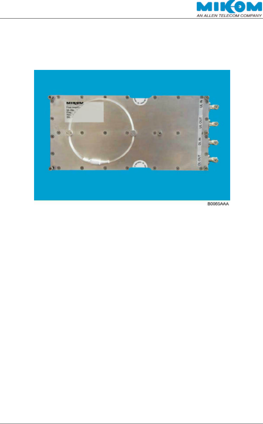
2.3.4. Final Amplifier
The UL- and DL path are amplified by a final amplifier. It is located next to the
conversion module.
figure 2-4 Final amplifier

USER´S MANUAL FOR BAND SELECTIVE REPEATERS MRX03P
User'sManual.doc Id.-No.:154999 Page 15 22-Jan-01
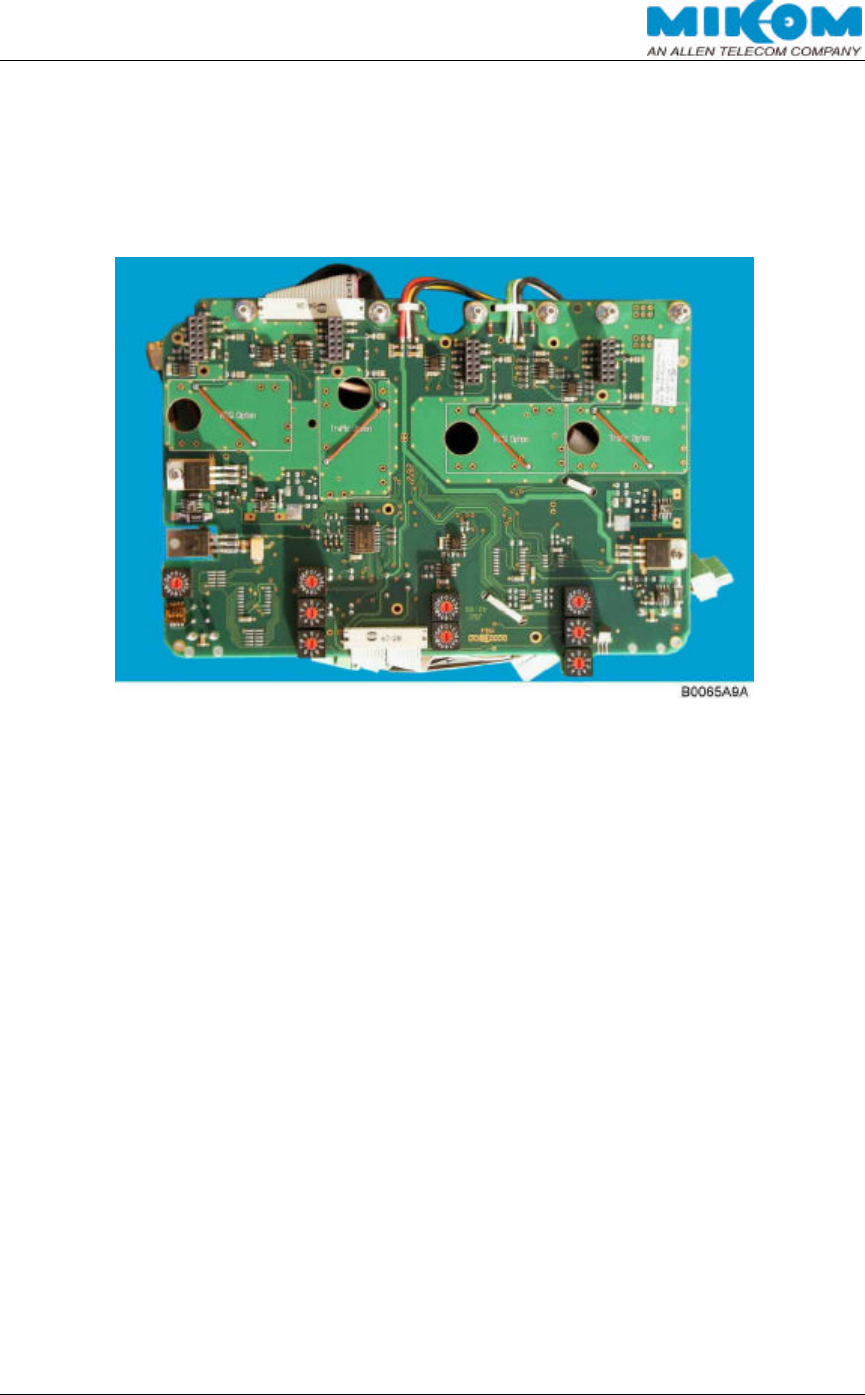
2.3.5. Control Module
The control module is a DOS compatible micro computer. The whole communication
between the provider and the repeater can be done via the control module.
The repeater can be controlled remotely or locally via a VT100 terminal or a PC
emulating the VT100 terminal.
To control the repeater remotely, use either the RS232 interface in connection with a
wireless modem or the PCMCIA interface in connection with a modem card and a
mobile or PSTN network adapter. The RS232 interface and the PCMCIA interface
are located on the control module.
Frequency, gain, power down of RF stages and ALC can be controlled and status
messages can be received remotely. In case a PSTN modem or a mobile is
connected, automatic alarm messages can be received.
The data transfer between the control module and the mother board is realized by
the I2C-Bus system.
The I2C-Bus concept was developed by Philips for the serial connection of integrated
circuits within one device. Two wires, serial data (SDA) and serial clock (SCL), carry
information between the devices connected to the bus. Each device is recognized by
a unique address and can operate either as transmitter or receiver.
All MRx03P configuration parameters are non-volatile stored in an EEPROM on the
control module if power supply failure occurs.
figure 2-5 Control module
USER´S MANUAL FOR BAND SELECTIVE REPEATERS MRX03P
User'sManual.doc Id.-No.:154999 Page 16 22-Jan-01
2.3.6. Motherboard
The function of the mother board is the communication between the conversion
module and the control module via the I2C-Bus. All signals will be recognized from
the mother board logic.
figure 2-6 Motherboard
USER´S MANUAL FOR BAND SELECTIVE REPEATERS MRX03P
User'sManual.doc Id.-No.:154999 Page 17 22-Jan-01
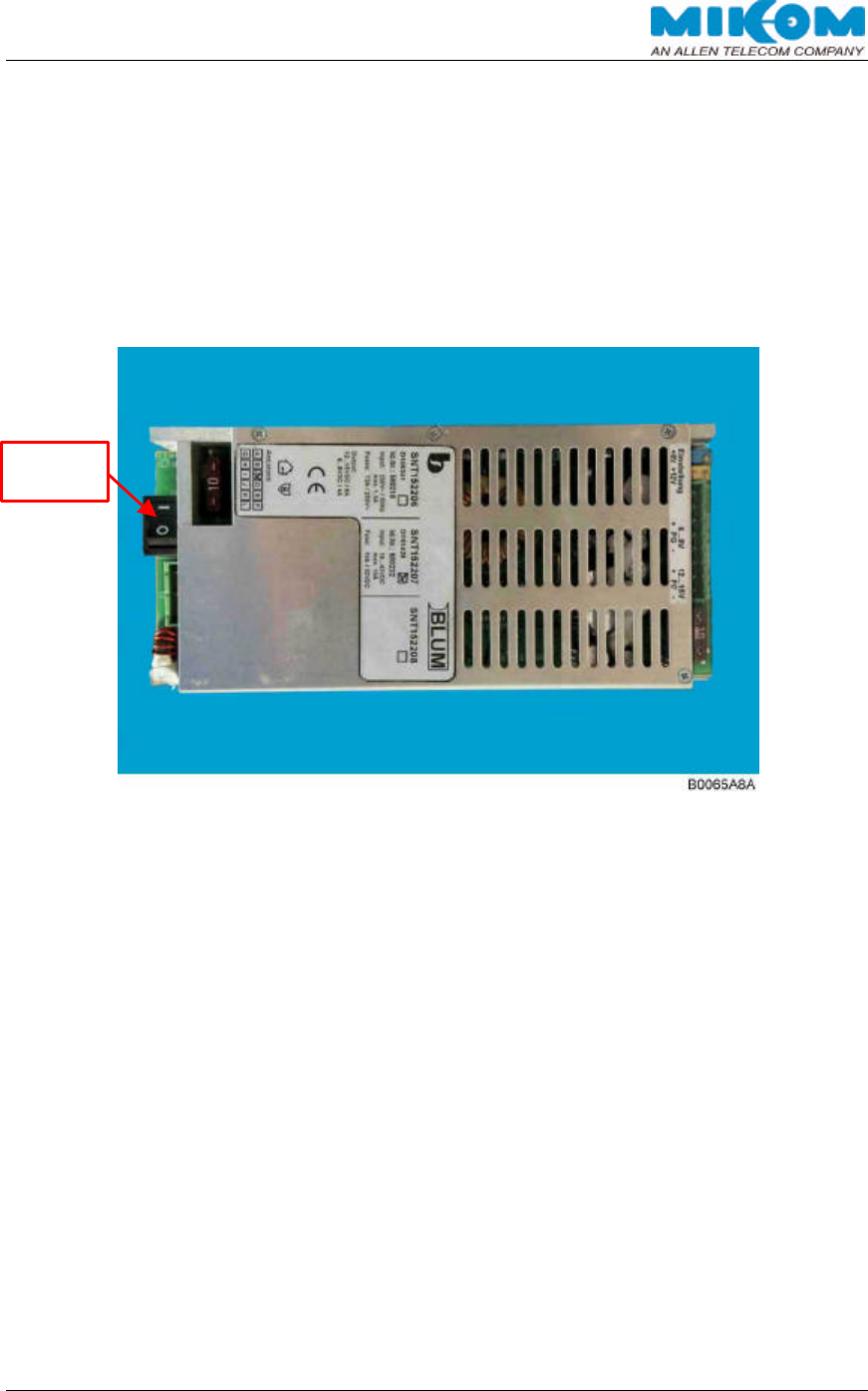
2.3.7. Power Supply
The power supply can be provided by different mains power. An external switch,
mounted on the power supply, is provided to disconnect the repeater from mains
during maintenance work to ensure that all circuits are voltage-free.
The power supply is factory-set and must not be changed. The power supply can be
fuse-protected.
figure 2-7 Power supply
External
Switch

USER´S MANUAL FOR BAND SELECTIVE REPEATERS MRX03P
User'sManual.doc Id.-No.:154999 Page 18 22-Jan-01
3. OPTIONAL EQUIPMENT
The actual repeater configuration can be seen at the configuration list which is part of
the delivery.
3.1. MODEM
The modem option enables the provider to set parameters and to query the status of
each repeater remotely. Furthermore, the modem can be set to send all occurred
alarms of the repeater directly to a provider’s terminal, e.g. to the OMC. This can be
done either via a wireless modem or a PSTN modem (Public Switched Telephone
Network). Thus, the alarms can be evaluated and eliminated promptly. It is possible
to install the wireless modem or the PSTN modem on site!
∫ Check the communication mode between the modem and the terminal. If
necessary, set the following parameters:
Bit rate / bit per second: 9600 baud Number of data bit: 8 bit
Parity bit: No parity Stopbit: 1 stopbit
These settings can only be changed after connection to the terminal. If a different
modem is required or if the quality of the line does not allow to use the set
parameters, the settings have to be changed in PC mode. The same applies for all
other parameters which can be set previously for modem mode by software.
3.1.1. Initstrings
Depending on the provider’s network and the used modem type, it is necessary to
adjust the initstring. The following initstrings are factory set:
Modem Network Initstring
Siemens M1* GSM900 ATE0S7=60S0=2\N6
Siemens M20* GSM900 ATZE0S0=2&S0+IFC=0,0+CBST=7,0,1
Motorola Mobile
MR30 “Surf–Pro”** PCS1900 AT*P1&F&K4E0S0=2\N0+CBST=7,0,1
MIKOM MO4000 GSM900/1800 ATE0S7=60S0=2;+CBST=7,0,1
PCMCIA-modem PSTN AT&FE0S0=2
* The Siemens M1 modem is no longer available and is replaced by the Siemens M20. In future, it is
assigned to replace all wireless modems working in GSM900/GSM1800 networks by the new MIKOM
modem MO4000.
**in connection with Cellect2 Card
table 3-1 Standard initstrings for modems
For further details to the initstrings, please refer to the user’s software manual.
USER´S MANUAL FOR BAND SELECTIVE REPEATERS MRX03P
User'sManual.doc Id.-No.:154999 Page 19 22-Jan-01
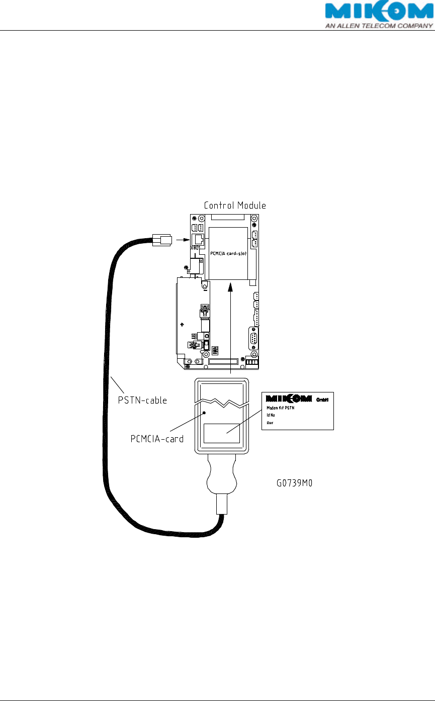
3.1.2. PSTN Modem
A Hayes compatible PSTN modem can be connected to the control module SM2009.
The telephone cable has to be fed through a labeled grommet of the connector panel
and must be connected to the designated clamps.
For the standard modem type DigiTel 56Euro, use clamps 2 and 3 to connect the
telephone lines a and b. Previous standard modems type DigiTel 34P use clamps 1
and 4. In case of failure try both possibilities to check the functionality of the modem
connection.
figure 3-1 Location of the PSTN Modem
∗ Note: If a PSTN modem is required, the DIP-switches of the Ext. Alarms-
switch [4] on the control module has to be set to position OFF
“PSTN Modem”. The DIP-switch 2 of the Mode-switch [1] has to be
set to position ON “Remote Mode”.
USER´S MANUAL FOR BAND SELECTIVE REPEATERS MRX03P
User'sManual.doc Id.-No.:154999 Page 20 22-Jan-01
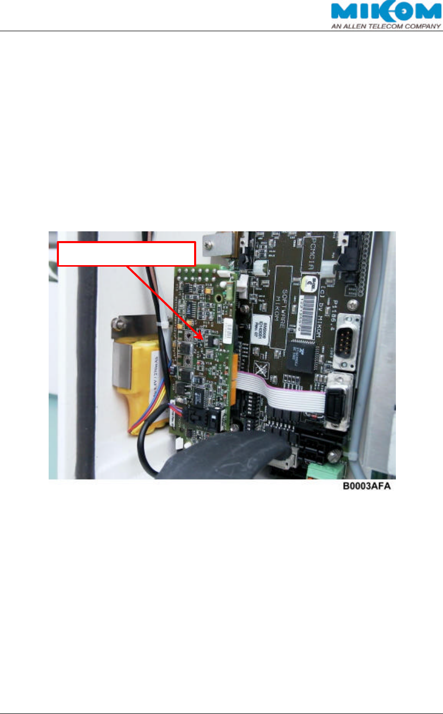
3.1.3. Wireless Modem
The wireless modem is mounted in the modem box of the lid.
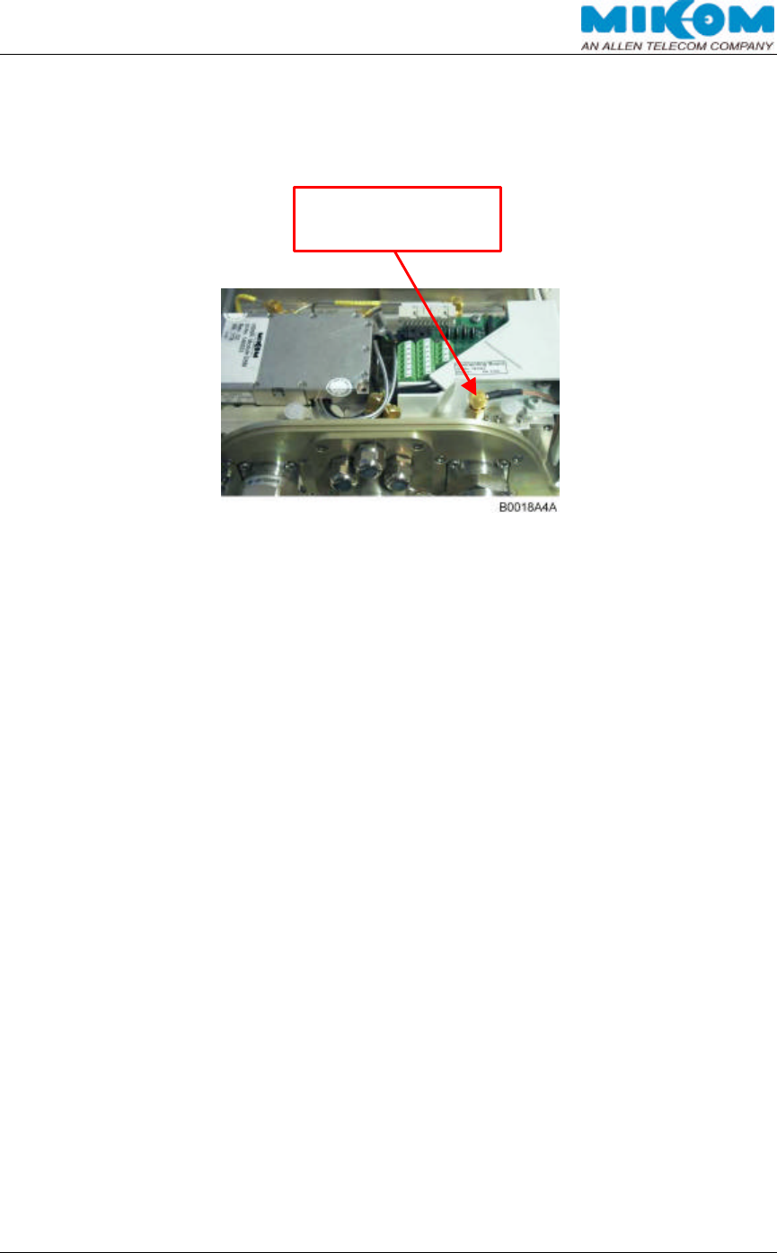
figure 3-2 Modem connection on the duplexer
Modem connection
on the duplexer
USER´S MANUAL FOR BAND SELECTIVE REPEATERS MRX03P
User'sManual.doc Id.-No.:154999 Page 21 22-Jan-01
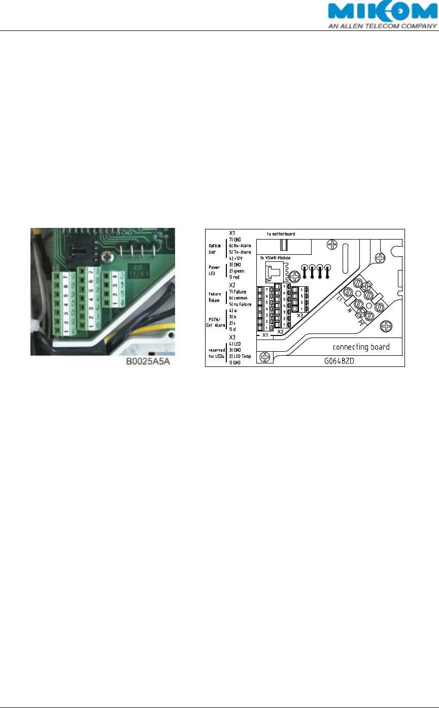
3.2. EXTERNAL ALARMS
With the external alarms option, it is possible to monitor the status of connected
devices via the repeater software, e.g. a UPS. The DIP-switches of the Ext.-Alarms
switch on the control module have to be set to position ON “Ext. Alarm 1-4”.
∗ Note: If a PSTN modem is required, only two external alarms are
available because the PSTN modem reserves two lines!
The connecting clamps are located on the connecting board mounted on the
duplexer (BTS side).
figure 3-3 Location of external alarm clamps
All external alarms are normally high (5V) without connection. Via the software
command SET LOGIC, the external alarms can be set to high active (H) or low active
(L). Depending on the settings, the external alarms show the status “failure” or “OK”
on the display. The configuration for open collector applications is 5V / 0.5 mA.
When only 2 external alarms are required, ensure that the other 2 external alarms are
set to low active, otherwise the status will always show an alarm.
∗ Note: The name for each external alarm and the name for the alarm
message can be defined by the customer with the corresponding
software command (see software manual)!
∗ Note: A special software blocking must be removed to use the external
alarm option. This can only be carried out by authorized persons
from MIKOM.
USER´S MANUAL FOR BAND SELECTIVE REPEATERS MRX03P
User'sManual.doc Id.-No.:154999 Page 22 22-Jan-01
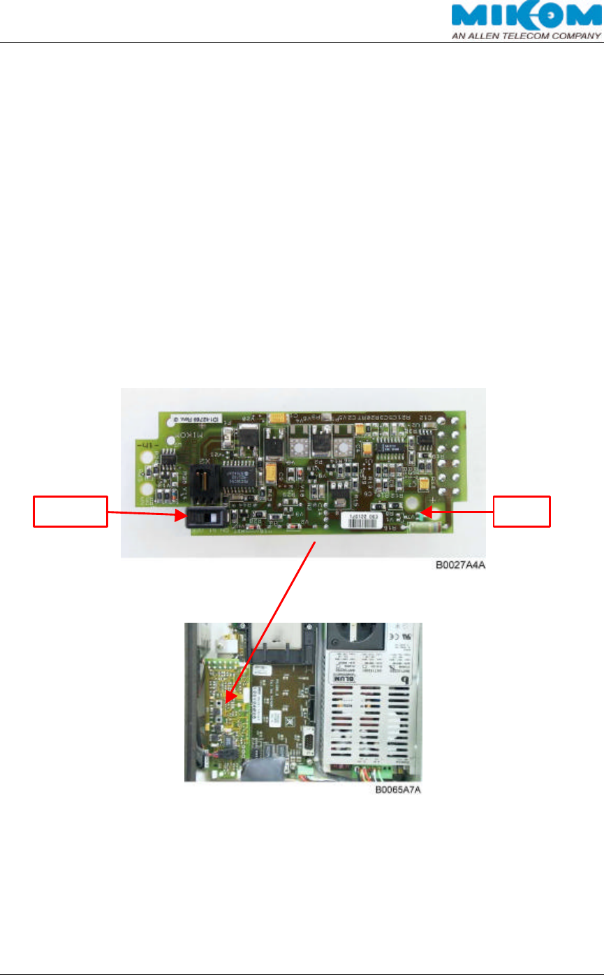
3.3. BATTERY BACKUP
The repeater can be provided with the battery backup option to enable alarm calls in
case of power failure. The battery backup module supports multiple dial out attempts
via modem in case of “System engaged” or other communication problems for about
ten minutes under normal environmental conditions.
The batteries are protected from deep discharge by use of a low voltage disconnect
unit. A local switch is provided to disconnect the battery backup option during
maintenance to ensure that all circuits are voltage-free. The switch is located on the
battery backup module.
The module is directly plugged onto the control module and can be installed on site.
During the charging process, a green LED on the module indicates that the battery is
charged at the moment. After finishing the process, the LED will be switched off.
figure 3-4 Location of the battery backup module
Switch
LED
USER´S MANUAL FOR BAND SELECTIVE REPEATERS MRX03P
User'sManual.doc Id.-No.:154999 Page 23 22-Jan-01
4. INSTALLATION
4.1. MECHANICAL INSTALLATION
4.1.1. General
F Note: Due to power dissipation the repeater may reach a very high
temperature. Therefore, it is necessary to mount the repeater
vertically to a wall or a mast without additional enclosure. A
clearance distance of one metre above and below the unit should be
kept to provide sufficient ventilation. Between the housing and the
wall, a minimum distance of 20 mm must be ensured.
F Note: The weight of the repeater is
approximately 14 kg in standard
configuration. Only adequate
manpower is allowed to handle
the weight of the system.
F Note: If it is impossible to mount the
repeater with the mounting
brackets due to an uneven
surface (e.g. a bulged wall in a
tunnel), alternative fastening
devices may be used. These
fastening devices must fulfil the
following requirements:
F Note: The external strain must not be
increased by the alternative fastening
devices. Holding devices, which expose
the repeater to enhanced vibration or shock
due to a greater distance from the wall (leverage)
or due to a lower rigidness or stability
(vibration), must not be used.
F Note: The repeater’s external strain specifications must not be exceeded,
particularly the exposure to vibration and shock (please refer to the
MIKOM “Environmental and Safety Leaflet” for further detailed
information).
F Note: Exceeding the specified load limits may cause the loss of warranty!
USER´S MANUAL FOR BAND SELECTIVE REPEATERS MRX03P
User'sManual.doc Id.-No.:154999 Page 24 22-Jan-01
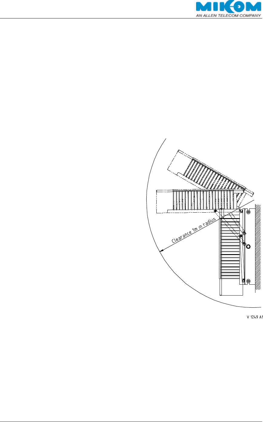
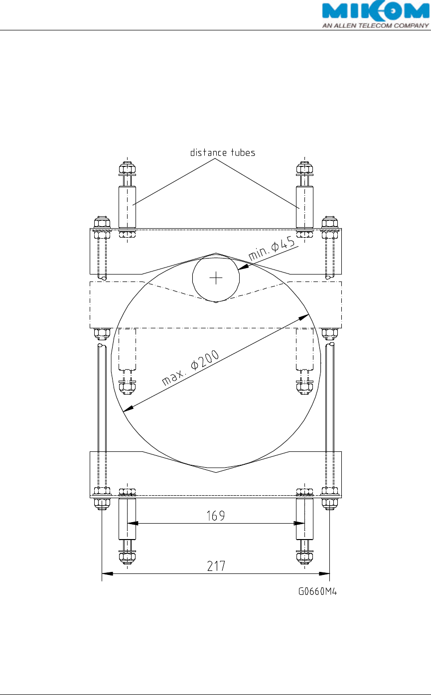
4.2. WALL MOUNTING PROCEDURE
Check the suitability of the wall mounting
kit and the wall.
∫ Dismount the mounting brackets which
are screwed to the housing with four
socket head cap screws M8x16 and two
tire bolts.
∫ Use the wall mounting template to mark
the position of the drilling holes. Drill four
holes and screw the mounting brackets to the wall.
∫ Attach the upper two socket head cap screws M8x16 to the repeater housing.
Hang the repeater into the mounting brackets.
∫ Fasten the lower two socket head cap screws M8x16 and the two tire bolts.
Ensure that there is free access to the electrical connections as well as to the
individual units inside the cabinet while the door of the repeater is open (clearance
distance of 1 m is recommended). The approved bending radius of the connected
cables must not be exceeded.
figure 4-1 Installation drawings of a repeater
USER´S MANUAL FOR BAND SELECTIVE REPEATERS MRX03P
User'sManual.doc Id.-No.:154999 Page 25 22-Jan-01
4.2.1. Pole Mounting Procedure
Standard mounting hardware can not be used to mount the repeater to a pole, a
mast or other similar structures. Additional hardware must be used for this type of
installation. Such a pole mounting kit could include two threaded rods M8, two U-
beams and mounting material like bolts and nuts.
figure 4-2 MIKOM pole mounting kits.

USER´S MANUAL FOR BAND SELECTIVE REPEATERS MRX03P
User'sManual.doc Id.-No.:154999 Page 26 22-Jan-01
Dismount the mounting brackets which are screwed to the housing with four socket
head cap screws M8x16 and two tire bolts (see figure 4-1 Installation drawings of a
repeater).
∫ Fasten the mounting kits and the mounting brackets to the pole or mast.
∫ Attach the upper two socket head cap screws M8x16 to the repeater housing.
∫ Hang the repeater into the mounting brackets.
∫ Fasten the lower two socket head cap screws M8x16 and the two tire bolts.
Make sure that there is free access to the electrical connections and to the individual
units inside the cabinet while the door of the repeater is open (clearance distance of
1 m is recommended). The allowed bending radius of the connected cables must not
be exceeded.
F Note: Two Mikom pole mounting kits are required to mount the repeater to
a pole or a mast.
USER´S MANUAL FOR BAND SELECTIVE REPEATERS MRX03P
User'sManual.doc Id.-No.:154999 Page 27 22-Jan-01
4.3. ELECTRICAL INSTALLATION
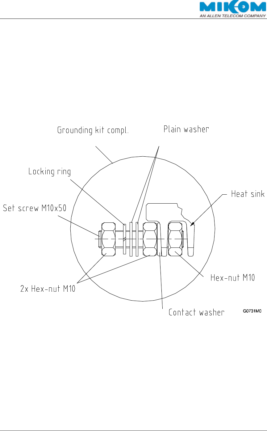
4.3.1. Grounding
Grounding must be carried out under all circumstances. An earth bonding cable must
be connected to the grounding bolt provided at the outside of the cabinet on the left-
hand side. Do not use the grounding screw for connecting external devices. The
complete grounding kit is part of the delivery schedule.
The complete grounding kit is part of the delivery schedule.
figure 4-3 Grounding bolt
4.3.2. Mains Power Supply
Before connecting electrical power to the repeater, it must be grounded. The repeater
is equipped with a firmly connected mains cable which is fed into the housing through
a watertight cable gland. Due to safety reasons, the power supply lead must be
protected by fuses. Inside the repeater, the mains cable is connected to a screw
terminal on the connecting board. In case the length of the power cable should not be
sufficient, it can be replaced by a longer cable.
USER´S MANUAL FOR BAND SELECTIVE REPEATERS MRX03P
User'sManual.doc Id.-No.:154999 Page 28 22-Jan-01
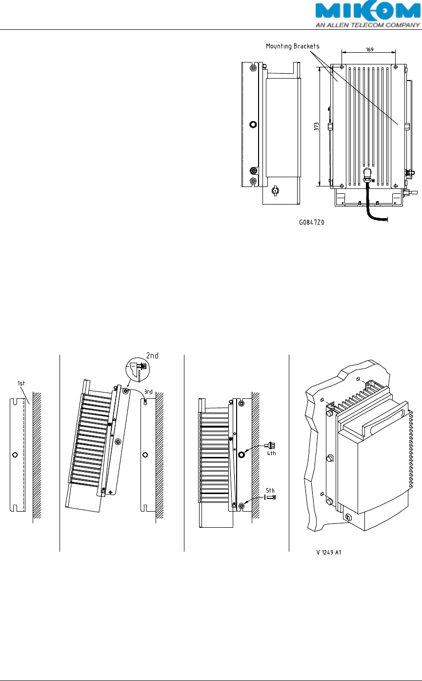
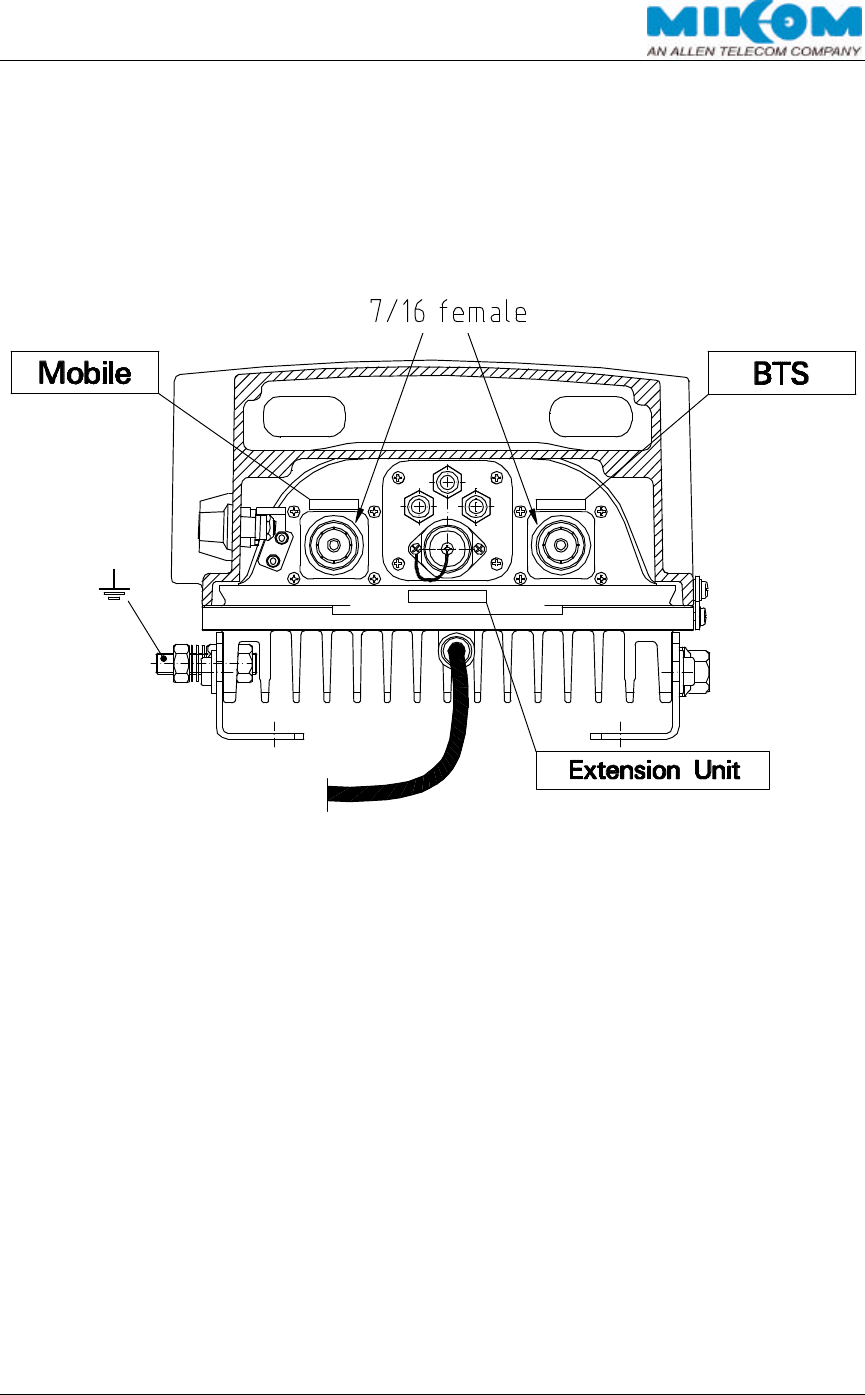
4.3.3. Antennas Connections
The repeater has two female antenna connectors 7/16 (or N with adapter). For
mounting the corresponding cable connector, we recommend to refer to the
corresponding documentation of the respective connector manufacturer. The bending
radius of the antenna cables must remain within its specification
G0847Z2
figure 4-4 Top view of antenna connections

USER´S MANUAL FOR BAND SELECTIVE REPEATERS MRX03P
User'sManual.doc Id.-No.:154999 Page 29 22-Jan-01
5. COMMISSIONING
5.1. PREPARATION
5.1.1. General
Please read the description carefully to avoid mistakes and proceed step by step as
described. The repeater must not be operated with open antenna ports. This means
that each antenna port has to be terminated with either a 50Ω resistor, a dummy load
or a connected antenna. The repeater could be damaged when operated without any
50Ω terminations.
When opening the repeater, do not damage the seals on the devices inside the
repeater. Warranty void if the seals are broken!
5.1.2. BCCH-Channel
Apart from the antenna isolation measurement described in chapter 5.1.3, it is also
necessary to measure the BCCH level (BCCH=Broadcast Control Channel). The
resulting max. allowed repeater gain of the antenna isolation must be compared with
the resulting max. allowed repeater gain of the measured BCCH channel. The lower
gain has to be set for the repeater.
The following example clarifies how to set the correct gain:
Antenna isolation: Antenna isolation: 100 dB
Safety Gain Margin (SGM)*: 15 dB
-------------
Allowed max. gain: 85 dB
BCCH channel: Power out**: +30 dBm
Received level of BCCH: -(-40) dBm
----------------
Allowed max. gain: 70 dB
* Refer to chapter 5.1.3 Antenna Isolation for further information about SGM.
** Max. Pout required by customer, but not higher than the rated Pout per channel stated for this
repeater at the required number of channels.
In this case, 70 dB gain has to be set for the repeater.
∗ Note: If a higher gain is set, the ALC will be active! This might affect the
quality of the signal!

USER´S MANUAL FOR BAND SELECTIVE REPEATERS MRX03P
User'sManual.doc Id.-No.:154999 Page 30 22-Jan-01
5.1.3. Antenna Isolation
Before setting the parameters of the repeater, ensure that the antenna isolation is
measured and optimized. The Safety-Gain-Margin (SGM) between the antenna
isolation and the maximum gain of the repeater is specified to +15 dB for all RF-
repeaters, i.e. the gain has to be -15 dB less than the isolation value of the antennas.
For better antenna isolation, ICE (Interference Cancellation Equipment) has been
developed for channel selective repeaters in the GSM900/1800 networks as well as
for PCS1900. ICE is specified for a SGM of –5 dB. Following example will show the
significant difference of a repeater with ICE-option compared to a repeater without
ICE-option.
Assumed case of a poor antenna isolation:
• Repeater without ICE
Antenna isolation: 80 dB
SGM: - 15 dB
-------------
Allowed max. gain: 65 dB
In this case, the antenna isolation should be improved. The operator has to enlarge
the distance between both antennas or has to shield each antenna from the other.
Sometimes, it is difficult to enlarge the distance or to shield the antenna to reach the
necessary value.
The next example clarifies how to solve the antenna isolation problem with an ICE-
repeater. The SGM between the antenna isolation and the maximum gain is specified
to -5 dB, i.e. the gain can be +5 dB more than the isolation value of the antennas.
Assumed case of the same poor antenna isolation as in the previous example:
• Repeater with ICE-option
Antenna isolation: 80 dB
SGM with ICE-option: +5 dB higher
----------------------
Allowed max. gain: 85 dB
For further details to ICE or antenna isolation, please refer to MIKOM “Application
Note for Antenna Isolation” or “ICE Datasheet”.
USER´S MANUAL FOR BAND SELECTIVE REPEATERS MRX03P
User'sManual.doc Id.-No.:154999 Page 31 22-Jan-01
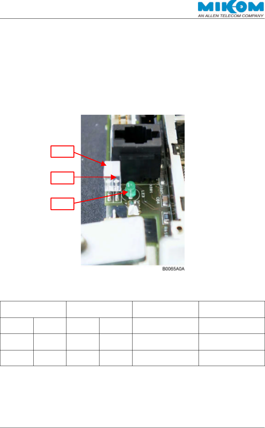
5.2. BOOT PROCESS
As soon as the repeater is switched on, the control module of the repeater starts the
boot process; LE3 displays “Power on”. The initialization of the hardware is part of
the boot process. The whole process may take up to several minutes.
After booting the system, LE1 turns red for a few moments, then flashes green. LE2
also flashes red and then green. This is just an optical functionality test of the two-
coloured LEDs.
figure 5-1 Control module – Position of LEDs
Internal
LED LE1 Internal
LED LE2 Internal
LED LE3 Cause
green Power on
Software booting
Flashes red
for a short
time
Flashes red
for a short
time green LED test
green green green Software boot
successful
table 5-1 LED indication during boot process
LE3
LE2
LE1
USER´S MANUAL FOR BAND SELECTIVE REPEATERS MRX03P
User'sManual.doc Id.-No.:154999 Page 32 22-Jan-01
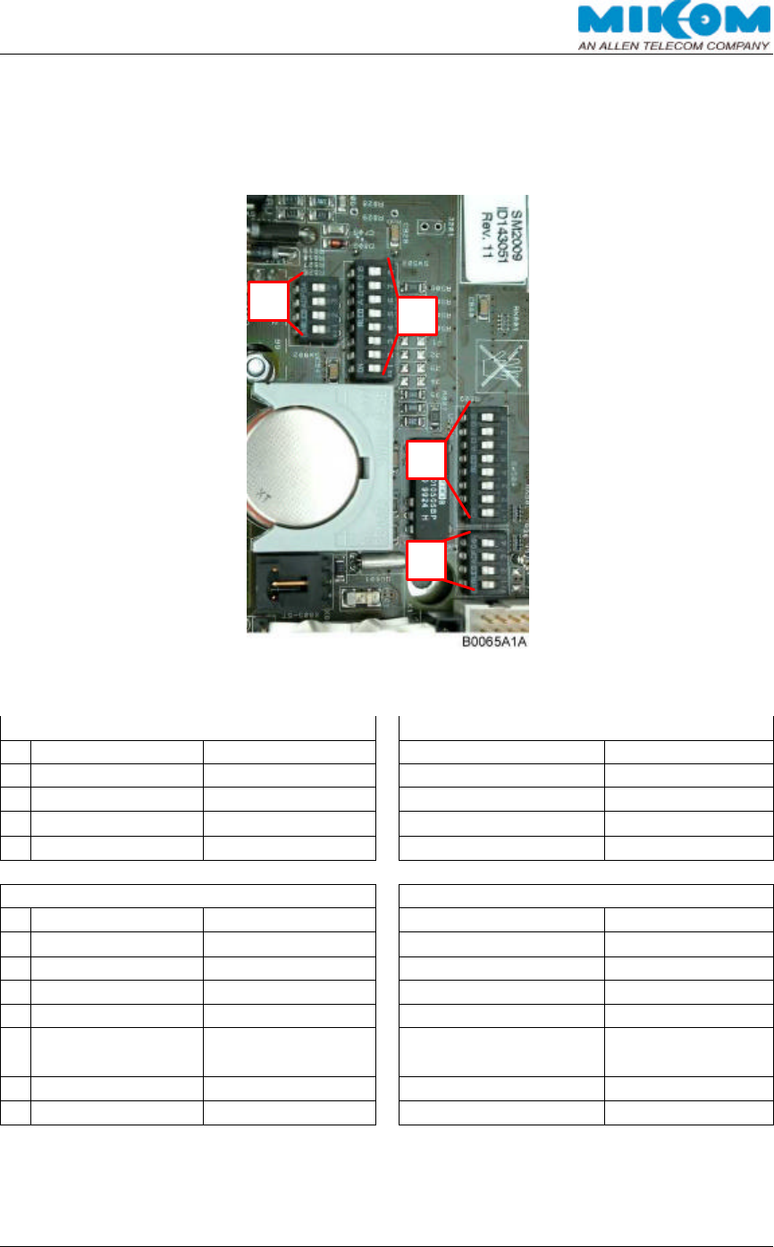
5.3. DIP-SWITCHES
The configuration of the DIP-switches on the control module is factory set.
figure 5-2 Control module – Position of the DIP-switches
Mode-switch [1]*
Ext. Alarms-switch [4]
ON OFF
ON OFF
1
Manual Auto
1 Ext. Alarm 4 PSTN (d)
2
Remote Mode Local Mode
2 Ext. Alarm 3 PSTN (c)
3
DO NOT USE! DO NOT USE!
3 Ext. Alarm 2 PSTN (b)
4
DO NOT USE! Auto
4 Ext. Alarm 1 PSTN (a)
Switch for additional inputs [2]**
MOR/MR-switch [3]
ON OFF
ON OFF
1
VCC O.C.
1 MR MOR
2
VCC O.C.
2 MR MOR
3
VCC O.C.
3 MR MOR
4
VCC O.C.
4 MR MOR
5
VCC O.C.
5 MOR MR
6
VCC O.C.
6 MOR MR
7
VCC O.C.
7 MOR MR
8
VCC O.C.
8 MOR MR
* Switch 1, 3 and 4 are factory set to position Off
** Switch for additional inputs not in use!
table 5-2 DIP-switches of control module
1
2
3
4
USER´S MANUAL FOR BAND SELECTIVE REPEATERS MRX03P
User'sManual.doc Id.-No.:154999 Page 33 22-Jan-01
5.4. REMOTE SETTINGS
After the boot process, the software login is possible. All parameters of the software
can be changed by the provider to optimize the repeater according to the network
system. There are two possibilities how to login to the software:
∫ locally via a VT100 terminal or a PC with VT100 terminal emulation
∫ remotely via a modem e.g. with the Operations and Maintenance Center (OMC)
5.4.1. Local Login
The login via VT100 terminal or a PC with VT100 emulation can only be performed at
the repeater. Open the repeater carefully and ensure that DIP-switch 2 of mode-
switch [1] is in position OFF. Only when DIP-switch 2 is OFF, a local access to the
software on the control module is possible (see chapter 5.3 DIP-Switches).
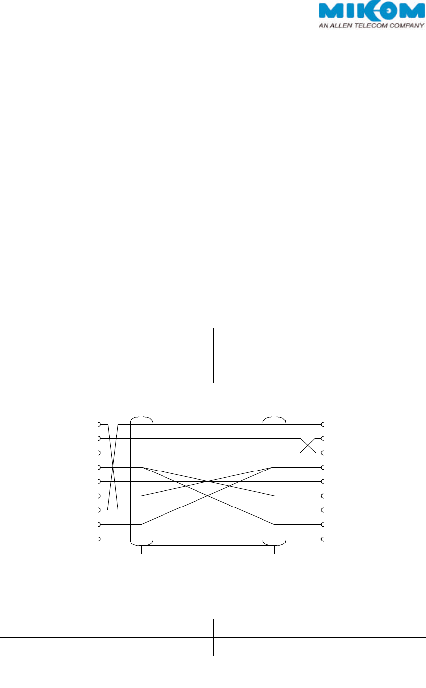
Connect the terminal or PC to the RS232 interface on the control module by means
of a standard RS232 interface cable (see picture below).
Terminal or PC Control Module SM2009
9 contact SUB-D-connector 9 contact SUB-D-connector
male male
Pin Pin
1
2
3
4
5
6
7
8
9
8
9
7
6
1
3
4
5
2
Check the communication mode at the terminal. If necessary, set the following
parameters:
Bit rate / bit per second: 9600 baud Number of data bit: 8 bit
Parity bit: No parity Stopbit: 1 stopbit

USER´S MANUAL FOR BAND SELECTIVE REPEATERS MRX03P
User'sManual.doc Id.-No.:154999 Page 34 22-Jan-01
∗ Note: The input is case sensitive, no blanks allowed. The connection will
be torn down after three wrong inputs!
There are two possibilities to login to the repeater software:
Repeater off: The repeater is switched off, the RS232 interface cable is already
connected and the DIP-switch 2 of the mode-switch (1) is set to
positon OFF.
After switching on the repeater, the boot procedure starts. Subsequently, the display
of the terminal shows following report.
-----------------------------------------------------------------------------------------------------------------
AT
MIKOM REPEATER MRXXX – SM2009 -SW: REP 10XX VX.XX
ENTER <.> <CR> TO LOGIN
-----------------------------------------------------------------------------------------------------------------
Please type
<.> (fullstop) and confirm with <CR> (carriage return)
to get to the login orders.
∗ Note: The following step can only be carried out by qualified personnel
in consideration of the health and safety warnings. Pay attention
not to touch devices while the repeater is operating!
Repeater On: The repeater is operating.
After connecting the RS232 interface cable and changing the mode-switch (1) DIP-
switch 2 to OFF, the display won´t show a report.
Please type
<.> (fullstop) and confirm with <CR> (carriage return)
to get to the login orders.
∗ Note: Sometimes it is necessary to type the <.> (fullstop)-command twice
or three times to get access to the repeater software.

USER´S MANUAL FOR BAND SELECTIVE REPEATERS MRX03P
User'sManual.doc Id.-No.:154999 Page 35 22-Jan-01
After successful login, the USERID is required.
-----------------------------------------------------------------------------------------------------------------
ENTER USER ID:
-----------------------------------------------------------------------------------------------------------------
Please enter
<UserID1>* and confirm with <CR> (carriage return).
* UserID1 is factory set and can be changed by software
Note case sensitivity and blanks!
Now, the correct password is asked. Following order will be displayed on the
terminal:
-----------------------------------------------------------------------------------------------------------------
ENTER PASSWORD:
-----------------------------------------------------------------------------------------------------------------
Please enter
<P-word1>** and confirm with <CR> (carriage return).
** P-word1 is factory set and can be changed by software
Note case sensitivity and blanks!
If the software-login procedure was successful, the input request shown below
displays on the terminal:
-----------------------------------------------------------------------------------------------------------------
MIKOM >
-----------------------------------------------------------------------------------------------------------------
All parameters of the repeater can now be changed to optimize the repeater to the
network system.
5.4.2. Remote Login
A login e.g. via modem at the OMC enables the operator to set parameters and to
query the status of each repeater. This can be done either via a wireless modem or a
PSTN-modem. The access commands to the repeater-software are the same as
described in chapter 5.4.1 Local Login. If the OMC is used for the remote login, the
input “<.> (fullstop) and <CR> (carriage return)” is skipped and UserID and Password
are requested right away.
USER´S MANUAL FOR BAND SELECTIVE REPEATERS MRX03P
User'sManual.doc Id.-No.:154999 Page 36 22-Jan-01
For further details to software-login and software-commands, please refer to the
user´s software.
5.5. MANUAL SETTINGS
Normally, settings are carried out by a VT100 terminal or PC. Additionally, if
manual settings are unavoidable, rotary switches on the motherboard enables
the operator to optimize the gain and to set the channels.
To enable the manual setting of attenuation and channels, ensure that the DIP-switch
1 of the mode switch [1] is in position ON (manual mode). An attenuation of 30 dB
max. in steps of 2 dB can be set in the UL- and DL path for channel and band
selective repeaters. The channel settings are only available for channel selective
repeaters.
∗ Note: While DIP-switch 1 of mode switch (1) is in position ON (manual
mode), software settings via VT100 terminal are not possible!
Quering the status can still be carried out.
figure 5-3 Motherboard
Example: Position 0 of the rotary switches S7/S8 equals 0 dB attenuation. Position 1
attenuates the signal by 2 dB, position 8 for instance attenuates by 16 dB. To
achieve max. attenuation (30dB), turn the rotary switch of the corresponding path to
position F.
S4
S5
S6
S7
S8
S9
S1
S2
S3

USER´S MANUAL FOR BAND SELECTIVE REPEATERS MRX03P
User'sManual.doc Id.-No.:154999 Page 37 22-Jan-01
The following table and the example show how to use the rotary-switches*:
Switch
Description
S1 Channel code x100
S2 Channel code x10
S3 Channel code x1
S4 Channel code x100
S5 Channel code x10
S6 Channel code x1
S7 Attenuation in 2 dB steps upto 30 dB for UL-path
S8 Attenuation in 2 dB steps upto 30 dB for DL-path
S9 Code switch for motherboard
* Factory settings are: S1-S8 in position 0, DIP-switch 1 of mode switch [1] in position “Off” (Automatic
mode). Switch S9 can be set to position 0 to 3 depending on the location of the motherboard in the
repeater.
table 5-3 Rotary switches of the motherboard
Example:
A gain of 74 dB is required in the UL- and DL-path, module 1 is set to channel 96 and
module 2 to channel 113. The repeater has a gain of max. 82 dB.
1. Calculate the difference between the max. repeater gain and the required gain.
Max. repeater gain: 82 dB
Required gain for UL and DL: 74 dB
-------------
Required attenuation for UL and DL: 8 dB
2. Turn switch S7 as well as S8 to position 4 to set an attenuation of 8 dB for UL- and
DL-path.
3. Set channel 96 for module 1:
Turn switch S1 to position 0: 0
Turn switch S2 to position 9: 90
Turn switch S3 to position 6: 6
--------
Channel: 96
4. Set channel 113 for module 2:
Turn switch S4 to position 1: 100
Turn switch S5 to position 1: 10
Turn switch S6 to position 3: 3
--------
Channel: 113

USER´S MANUAL FOR BAND SELECTIVE REPEATERS MRX03P
User'sManual.doc Id.-No.:154999 Page 38 22-Jan-01
5.6. LEVELLING OF THE REPEATER
After software-login, the repeater must be levelled so that the highest output power is
achieved without reaching the ALC (Automatic Level Control).
∗ Note: When the local software configuration is finished, don´t forget to
switch back DIP-switch 2 of the mode-switch to position ON,
otherwise the remote mode via modem will not work!

USER´S MANUAL FOR BAND SELECTIVE REPEATERS MRX03P
User'sManual.doc Id.-No.:154999 Page 39 22-Jan-01
6. ALARMS
6.1. BITE AND ALARMS
The Built-In Test concept comprises the monitoring of the power supplies, the
operational currents in the conversion modules, the motherboard and the remote
control interface. Furthermore, the synthesizer lock and the temperature of the
repeater are monitored.
All occurred alarms can be checked via software by typing the “STATUS HIST”
command. The provider is then able to acknowledge the alarm manually by the
software command “ALARMACKN”, e.g. ALC active, RSSI, door open or stabilty
control. If all alarms have been acknowledged, the summary error LEDs are set back
to green indication.
If monitored via a modem, automatic dialling will generate a summary alarm
message. The provider can acknowledge the alarm message and can request a
detailed status report.
6.2. HANDLING OF ALARMS
As soon as the software recognizes a valid alarm, a message is transmitted to the
operator. In remote mode, the alarm can be acknowledged by simply ringing back
and typing ALARMACKN.
If the reason for the alarm has been cleared or if the alarm should continue, a new
alarm message will not be repeated. If there was an interruption of at least one
second after acknowledgement, a new alarm message will be generated.
6.3. STATUS REPORT
Two instructions enable the operator to get the information of the system status.
Typing GET, commands will be responded by a listing of all settings of the repeater.
STATUS will be responded by a listing of all individual status information which can
be monitored only, but not influenced by SET commands.
The complete listing of the syntax with the processor of the control module including
the instructions and the messages as well as all available alarms from the system is
obtainable as a separate software manual.
USER´S MANUAL FOR BAND SELECTIVE REPEATERS MRX03P
User'sManual.doc Id.-No.:154999 Page 40 22-Jan-01
7. TROUBLE SHOOTING
7.1. ERROR INDICATION
• = LED on
- = LED off
1. With implemented battery backup module
Internal
LED LE1 Internal
LED LE2 Internal
LED LE3 Cause
green
red green red green
-
-
-
-
-
No power.
Check presence of
power at the input;
replace fuse according
to chapter, check
battery backup module
l
l
l Indicates a
summary failure
l
l
l Mains failure, control
module is supplied from
battery backup module
2. Without battery backup module
Internal
LED LE1 Internal
LED LE2 Internal
LED LE3 Cause
green
red green red green
-
-
-
-
-
No power.
Check presence of
power at the input;
replace fuse
l
l
l Indicates a
summary failure

USER´S MANUAL FOR BAND SELECTIVE REPEATERS MRX03P
User'sManual.doc Id.-No.:154999 Page 41 22-Jan-01
7.2. BOOT PROCESS
Following signals occur during boot process
Internal
LED LE1 Internal
LED LE2 Internal
LED LE3 Status
green red green red green
- - - - l Power on state, Software
boot starts
l Flashes
red short
time
l Flashes
red
short
time
l Software boot starts
l l l Software is running
The boot process takes about 3 minutes
7.3. ALARM MONITORING WITH THE ALARM HISTORY
Check the alarm history.
1. If a hardware module is damaged, replace corresponding hardware module.
2. Minor alarms with no influence on the system can be cancelled by confirming the
alarm with the software command ‘alarmackn’, e.g., DOOR OPEN.
3. If all alarms have been acknowledged the summary error LEDs will be set back to
green indication.
4. In case of mains power failure the contents of the actual alarm history list will be
lost.
List with all available alarms in the alarm history.
7.4. POWER SUPPLY
Factory set output voltages ( with load )
• 7.8 V ± 0.1 V
• 12.4 V ± 0.1 V
In case of an I²C-Bus error, also check the power supplies. They must be switched to
position ON.

USER´S MANUAL FOR BAND SELECTIVE REPEATERS MRX03P
User'sManual.doc Id.-No.:154999 Page 42 22-Jan-01
7.5. GENERAL REMARKS
∫ After a software download previous user settings ( data default values ) might be
overwritten. Before you start a software download save all user settings:
- attenuation
- ALC threshold
- temperature compensation offset ( gain )
- phone numbers etc.
∫ If an ALC alarm occurs during installation or commissioning an user error might
be the cause, due to wrong measurements, e.g.
ALC: Input level too high à reduce gain

USER´S MANUAL FOR BAND SELECTIVE REPEATERS MRX03P
User'sManual.doc Id.-No.:154999 Page 43 22-Jan-01
8. MAINTENANCE
8.1. GENERAL
∗ Note The repeater does not require preventative maintenance measures.
It is only recommended to replace the RAM/RTC battery and the whole battery
backup module after three years usage as a prophylactic measure. The nominal
lifetime of these batteries is five years under normal environmental conditions.
In the event of a malfunction, it is advantageous to check the status of the antenna
systems as well as the continuity of the entire cabling including connectors before
replacing the modules.
Maintenance on the repeater shall be performed by replacing modules only.
Soldering on printed circuit boards shall be avoided. In order to sustain warranty, take
care not to damage unintentionally the seals on the modules. To open the housing,
the upper screws have to be removed first and than the lower screws (see installation
drawing chapter 7.1). Proceed in reverse order to close the housing.
The spare parts list, consequently, contains only units which can be replaced without
tuning or complex soldering work. Those units are all MIKOM modules as well as
internal and external cables.
∗ Note Defect parts should only be replaced by original parts from
MIKOM. All interventions inside the housing are at one’s own risk.
∗ Note During maintenance ensure that the repeater has been
disconnected from mains and the battery backup module has been
switched off.
USER´S MANUAL FOR BAND SELECTIVE REPEATERS MRX03P
User'sManual.doc Id.-No.:154999 Page 44 22-Jan-01
8.2. REPLACEMENT OF THE FUSES
The power supply is protected with a primary fuse, type T6.3A / 250V.
figure 8-1 Fuse replacement
8.3. REPLACEMENT OF THE MAINS CABLE
In case the length of the delivered mains cable should not be sufficient or in case of a
defect, the mains cable can be replaced.
∗ Note: Disconnect repeater from mains first!
Remove the cover plate with the lock and open the housing by lifting the fixing clamp
The mains cable is now accessible from the bottom of the heat sink. Unscrew it from
the clamps on the connecting board (see figure 8-2 Connecting board) as well as the
small bar fixed with one tallow-drop screw M3.
figure 8-2 Connecting board
Fuse
USER´S MANUAL FOR BAND SELECTIVE REPEATERS MRX03P
User'sManual.doc Id.-No.:154999 Page 45 22-Jan-01
Loose the mounting screw of cable gland at the outside of the heat sink (see figure
8-3 Cable gland) and pull the cable through the hole.
For mounting a new mains cable proceed in reverse order.
∗ Note The diameter of the power supply lead has to be in the range of
9.5 mm max. and 6.5 mm min.
Strip the isolation of the cable to the length of 18 cm and pull it through the cable
gland like depicted in 8.4. Inside the housing, use the insulated tube.
figure 8-3 Cable gland
8.4. REPLACEMENT OF THE RAM / RTC BATTERY
The RAM/RTC battery of the control module has to be replaced in case of memory
loss or as a preventive measure after approximately three years usage. The
RAM/RTC battery is mounted underneath the battery backup module. It is accessible
after opening the housing on the left-hand side in the lid.
First remove the whole battery backup module (see chapter 8.5) which is plugged
into the control module. By means of a small screwdriver, placed between the battery
and the battery socket, the battery can be taken out of the battery socket.
The type of the battery is CR 2450 Lithium 3V/500mAh, manufacturer is RENATA.
After replacement of the RAM battery, the control module has its basic settings.
USER´S MANUAL FOR BAND SELECTIVE REPEATERS MRX03P
User'sManual.doc Id.-No.:154999 Page 46 22-Jan-01
figure 8-4 Position of RAM/RTC battery
∗ Note Before replacing the battery, disconnect the repeater from mains
and take off the battery backup module.
∗ Note Observe the rules for changing Lithium batteries. Wrong
connection or treatment may result in bursting of the battery and
dissemination of hazardous substances.
∗ Note Don’t try to charge this battery.
USER´S MANUAL FOR BAND SELECTIVE REPEATERS MRX03P
User'sManual.doc Id.-No.:154999 Page 47 22-Jan-01
8.5. REPLACEMENT OF THE BATTERY BACKUP MODULE
The battery backup module has to be replaced in case of memory loss or as a
preventive measure after approximately three years usage. The nominal lifetime of
the accumulator is three years. The battery backup module is accessible after
opening the housing on the left-hand side in the lid. It is recommended to replace the
whole battery backup module which is plugged into the control module.
Before disconnecting the module from the socket, release the three snap-in lockings.
The control module has its basic settings after replacement.
figure 8-5 Battery backup module
Battery Backup Module

USER´S MANUAL FOR BAND SELECTIVE REPEATERS MRX03P
User'sManual.doc Id.-No.:154999 Page 48 22-Jan-01
8.6. DUPLEXER
• On side of the BTS antenna connector:
Dismount connecting board first if the duplexer has to be replaced (see chapter 6.11).
Dismount the amplifier, mounted on the backside of the duplexer on the side of the
DL input, by unscrewing two M2.5 Phillips screws. Take off the amplifier carefully.
Pay attention not to damage the three pilot pins.
Remove the flat cable to the mother board.
Remove the RF cables on the side of the UL output by loosing the SMA connector by
means of a torque wrench.
Unscrew the four counter sunk screws M3 at the connector panel.
Remove the grounding cable.
• On side of mobile antenna connector:
Dismount the amplifier, mounted on the backside of the duplexer on the side of the
UL input, by unscrewing two M2.5 Phillips screws. Take off the amplifier carefully.
Pay attention not to damage the three pilot pins.
Remove the RF cables on DL output by loosing the SMA connector by means of a
torque wrench.
Unscrew the four counter sunk screws M3 at the connector panel (see figure 2.2.4-1
Connector panel layout).
Remove the grounding screw which is fixed to the extension module with a Phillips
screw.
8.7. CONVERSION MODULE
Disconnect the SMA connectors by means of a torque wrench to remove the module.
Screw off the six hex socket screws by means of a hex socket key.
Pull the mounting strap carefully which is fixed on the conversion module and take off
the module.

USER´S MANUAL FOR BAND SELECTIVE REPEATERS MRX03P
User'sManual.doc Id.-No.:154999 Page 49 22-Jan-01
8.8. CONTROL MODULE SM 2009
The control module is a Printed Circuit Board and is situated in the lid of the housing.
Disconnect the DC cable from power supply.
Disconnect flat cable.
Remove the modem.
Take off the whole control module completely with chassis by unscrewing four nuts
M4 or the four knurled screws.
For mounting proceed in reverse order.
8.9. POWER SUPPLY
∗ Note Ensure that mains are disconnected and the battery backup
module is switched off.
The power supply is mounted in the lid of the housing. Open the repeater to get
access to the device.
Remove all connected cables from the clamps of the power supply. Remove the
ground cable.
The power supply is fastened to the lid of the housing by means of two nuts M4 on
the right-hand side. After loosen the screws, the power supply can be removed. A
special key with a mobile element will be required to open these screws.
∗ Note Don’t forget to put heat conducting paste on the mounting side for
installation of a new power supply. Use the conducting paste
which is included in the spare parts kit.

USER´S MANUAL FOR BAND SELECTIVE REPEATERS MRX03P
User'sManual.doc Id.-No.:154999 Page 50 22-Jan-01
8.10. CONNECTING BOARD
The connecting board is mounted on top of the duplexer on the right-hand side in the
heat sink.
It is screwed by means of three tallow-drop screws M3.
Disconnect the flat cable, mains cable, the cable to power supply and grounding
eyelet bolt.
figure 8-6 Connecting board

USER´S MANUAL FOR BAND SELECTIVE REPEATERS MRX03P
User'sManual.doc Id.-No.:154999 Page 51 22-Jan-01
9. APPENDIX
9.1. ELECTRICAL SPECIFICATIONS
9.1.1. Specifications of MR703P
Specifications MR703P
Frequency range MR703P-ADB
MR703P-EFC
MR703P-DBEF
UL:1850-1885 MHz, DL: 1930-1965 MHz
UL:1875-1910 MHz, DL: 1955-1990 MHz
UL:1865-1895 MHz, DL: 1945-1975 MHz
Bandwidth 0.2-
15 MHz, 2.5 dB gain degradation at
200 kHz
Gain 70 dB min., K
2 dB over frequency and
temperature range
Gain adjust range 30 dB in 2 dB steps
Spurious intermodulation -13 dBm max.
Noise figure (@ max. gain) UL and DL 8 dB max.
ALC dynamic range 10 dB
OICP-3 +44 dBm min.
P1dB +34 dBm min.
Return loss (@ 25°C amb. temp.) 10 dB min.
Power supply 110 Vac, 230 Vac, 24 Vdc or 48 Vdc
Power consumption 95 Watt typ.
Built in test equipment Current monitor
Synthesizer lock monitor
Temperature
ALC active
Alarm forwarding
Potential free relay contact and automatic
alarm call via RS232 or PCMCIA
interface
Control functions Gain
Center frequency
ALC threshold
RF connectors 2 x 7/16 female, N as an option
*Please contact the MIKOM sales office for further questions to available bandwidths.
GSM TDMA CDMA
Pout for 1 channel 34 dBm 31 dBm 27 dBm
Pout/channel for
2 channels 24 dBm 24 dBm 22 dBm
Pout/channel for
4 channels 20 dBm 20 dBm 19 dBm
table 9-1 Specification of MR703P
All data is subject to change without notice!

USER´S MANUAL FOR BAND SELECTIVE REPEATERS MRX03P
User'sManual.doc Id.-No.:154999 Page 52 22-Jan-01
9.1.2. Specifications of MR803P
Specifications MR803P
Frequency range MR803P-TR
MR803P-CE UL: 806-824 MHz, DL: 851-869 MHz
UL: 824-849 MHz, DL: 869-894 MHz
Bandwidth 0.2-
25 MHz, 2.5 dB gain degradation at
200 kHz
Gain 70 dB min., K
2 dB over frequency and
temperature range
Gain adjust range 30 dB in 2 dB steps
Spurious intermodulation -13 dBm max.
Noise figure (@ max. gain) UL and DL 8 dB max.
ALC dynamic range 10 dB
OICP-3 +44 dBm min.
P1dB +34 dBm min.
Return loss (@ 25°C amb. temp.) 10 dB min.
Power supply 110 Vac, 230 Vac, 24 Vdc or 48 Vdc
Power consumption 95 Watt typ.
Built in test equipment Current monitor
Synthesizer lock monitor
Temperature
ALC active
Alarm forwarding
Potential free relay contact and automatic
alarm call via RS232 or PCMCIA
interface
Control functions Gain
Center frequency
ALC threshold
RF connectors 2 x 7/16 female, N as an option
*Please contact the MIKOM sales office for further questions to available bandwidths.
Analog TDMA CDMA
Pout for 1 channel 34 dBm 31 dBm 27 dBm
Pout/channel for
2 channels 24 dBm 24 dBm 22 dBm
Pout/channel for
4 channels 20 dBm 20 dBm 19 dBm
table 9-2 Specification of MR803P
All data is subject to change without notice!

USER´S MANUAL FOR BAND SELECTIVE REPEATERS MRX03P
User'sManual.doc Id.-No.:154999 Page 53 22-Jan-01
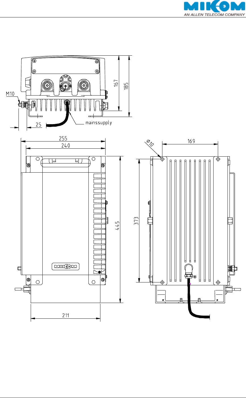
9.2. MECHANICAL SPECIFICATION
Standard cabinet:
Max. Height x Width x Depth: 445 x 255 x 167*/185 mm (Main Unit)
*without mounting brackets
Volume: < 14 litres
Weight: approximately 14 kg per unit, standard configuration
9.3. ENVIRONMENTAL AND SAFETY SPECIFICATIONS
For detailed information, refer to the environmental and safety specification leaflet for
MIKOM indoor/outdoor cell enhancers, related to ETS 300 019 (European
Telecommunication Standard).
Operating temperature:
• Normal temperature range: +5°C...+40°C
• Extreme temperature range: -33°C +50°C
Humidity: 90% @ +30°C
USER´S MANUAL FOR BAND SELECTIVE REPEATERS MRX03P
User'sManual.doc Id.-No.:154999 Page 54 22-Jan-01
9.4. SPARE PARTS LISTS
The following lists contain all parts available for the MRx03P. The configuration of the
delivered unit meets the requirements of the customer and can differ depending on
the state of the delivery.
9.4.1. Spare Parts List of MR703P
Repeater: Repeater Id.-No.:
MR703P-ADB: 154856 --- ---
MR703P-EFC: --- 154861 ---
MR703P-DBEF: --- --- 154862
Id.-Nos.: Designation: MR703P
ADB MR703P
EFC MR703P
DBEF
PCS-Duplexer UL 144382 144384 151072
PCS-Duplexer DL 144381 144383 151073
Basic Module var. 15 MHz 151463
Final Amplifier 4 Watt 154737
Power supply, no plug, 185-320 Vac 148812
Power Supply, no plug, 230 Vac ±15% 144306
Power Supply, USA plug, 115 Vac ±15% 141230
Power Supply, no plug, 80-130 Vdc 145524
Power Supply, no plug, 36-72 Vdc 144946
Power Supply, no plug, 18-43 Vdc 145504
MO4000 Kit 154633
I2C-Board 153144
Modem Kit PSTN 143112
Ext. Alarms SW-Option 145067
2 Ext. Alarms + PSTN 148272
Battery Backup Module 143052
SW MOB100 V1.10 143055
SW REP1009 V1.11 147127
Mother Board 148968
Connecting Board 142362
Control Unit SM4000 151957
Control Unit SM2009 143051
table 9-3 Spare parts list of MR703P
Mikom reserves the right to replace the spare parts listed above by equivalent
substitutes!

USER´S MANUAL FOR BAND SELECTIVE REPEATERS MRX03P
User'sManual.doc Id.-No.:154999 Page 55 22-Jan-01
9.4.2. Spare Parts list of MR803P
Repeater: Repeater Id.-No.:
MR803P-CE: 806-824 MHz;851-869 MHz --- 155340
MR803P-CE: 824-849 MHz;869-894 MHz 155215 --
Id.-Nos.: Designation: MR803P-CE MR803P-TR
PCS-Duplexer UL 148334 148333
PCS-Duplexer DL 148335 148336
Basic Module var. 15 MHz 151976 150150
Final Amplifier 4 Watt 155191
Power Supply, no plug, 185-320 Vac 148812
Power Supply, no plug, 230 Vac ±15% 144306
Power Supply, USA plug, 115 Vac ±15% 141230
Power Supply, no plug, 80-130 Vdc 145524
Power Supply, no plug, 36-72 Vdc 144946
Power Supply, no plug, 18-43 Vdc 145504
MO4000 Kit 154633
I2C-Board 153144
Modem Kit PSTN 143112
Ext. Alarms SW-Option 145067
2 Ext. Alarms + PSTN 148272
Battery Backup Module 143052
SW MOB100 V1.10 143055
SW REP1009 V1.11 147127
Mother Board 148968
Connecting Board 142362
Control Unit SM4000 151957
Control Unit SM2009 143051
table 9-4 Spare parts list of MR803P
Mikom reserves the right to replace the spare parts listed above by equivalent
substitutes!
USER´S MANUAL FOR BAND SELECTIVE REPEATERS MRX03P
User'sManual.doc Id.-No.:154999 Page 56 22-Jan-01
9.5. INSTALLATION DRAWING OF THE REPEATER
figure 9-1 Installation drawing of MRx03P
USER´S MANUAL FOR BAND SELECTIVE REPEATERS MRX03P
User'sManual.doc Id.-No.:154999 Page 57 22-Jan-01
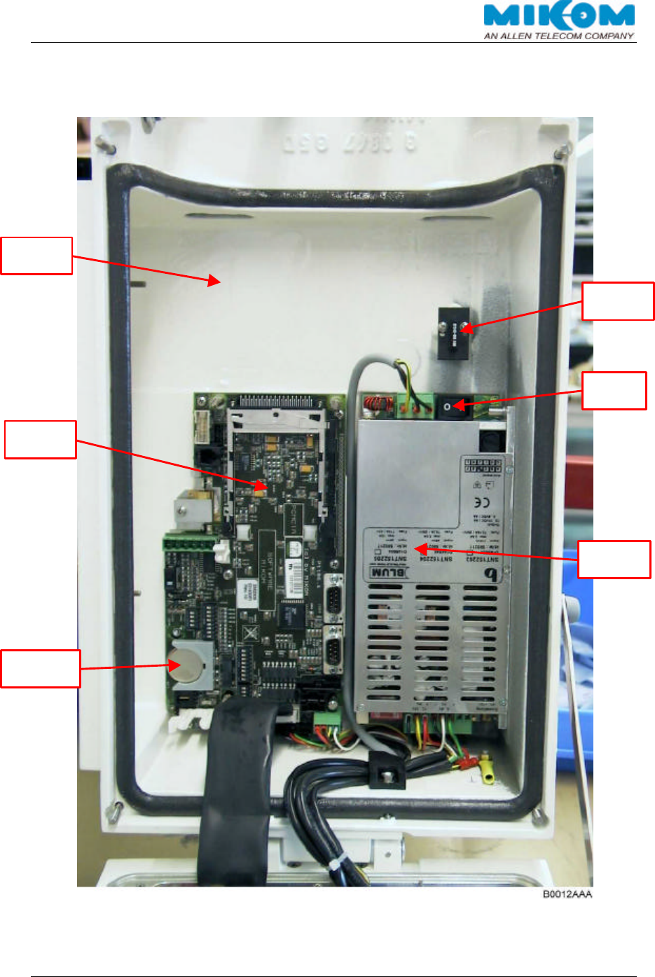
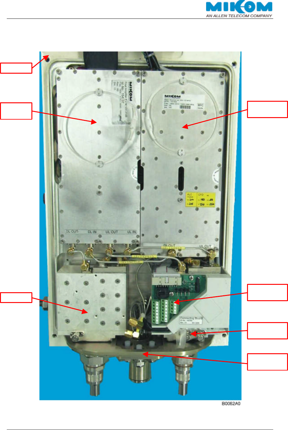
9.6. LAYOUT OF THE REPEATER LID
figure 9-2 Repeater lid
Mains
Switch
Door
Contact
Power
Supply
Repea
ter
Lid
Control
Module
RAM/RTC
battery
USER´S MANUAL FOR BAND SELECTIVE REPEATERS MRX03P
User'sManual.doc Id.-No.:154999 Page 58 22-Jan-01
9.7. LAYOUT OF THE REPEATER HEAT SINK
figure 9-3 Repeater heat sink
Heat sink
Final
Amplifier
Conversion
Module
Duplexer
Connector
Panel
Connecting
Board
Modem
Connector

USER´S MANUAL FOR BAND SELECTIVE REPEATERS MRX03P
User'sManual.doc Id.-No.:154999 Page 59 22-Jan-01
10. INDEX
A
Abbreviations................................................ 7
Address of MIKOM........................................ 9
Alarm
BITE and Alarms..................................... 39
Handling of............................................. 39
Status Report.......................................... 39
Alarm history............................................... 41
Antenna connections................................... 28
B
Battery Backup............................................ 22
Battery backup module
Replacement of ...................................... 47
Boot process......................................... 31, 41
C
Commissioning ........................................... 29
Communication mode parameters............... 18
Control Module............................................ 15
Conversion Module..................................... 13
D
DIP-switches............................................... 32
Duplexer..................................................... 12
E
External alarms........................................... 21
F
Final Amplifier............................................. 14
G
Grounding................................................... 27
H
Health and Safety Warnings.......................... 8
I
Initstrings .................................................... 18
Installation
Electrical................................................. 27
Mechanical ............................................. 23
L
List.............................................................. 10
Local Login ................................................. 33
M
Mains power supply .................................... 27
Maintenance............................................... 43
Manual settings........................................... 36
Measurements
Antenna isolation .................................... 30
BCCH-Channel....................................... 29
Levelling ................................................. 38
Measuring Aids........................................... 12
Modem (general)......................................... 18
Motherboard ............................................... 16
Mounting
Pole........................................................ 25
Wall ........................................................ 24
Mounting brackets....................................... 24
P
Power supply
Replacement of....................................... 49
Power Supply.............................................. 17
Preamble...................................................... 9
PSTN modem ............................................. 19
R
Remote Login ............................................. 35
Remote Settings ......................................... 33
Repeater
Installation Drawing.................................56
Layout of Heat Sink.................................58
Layout of Lid........................................... 57
Repeater design.......................................... 11
Replacement of
Battery Backup Module........................... 47
Connecting Board................................... 50
Control Module SM2009 ......................... 49
Conversion Module.................................48
Duplexer................................................. 48
Fuses ..................................................... 44
General................................................... 43
Mains Cable............................................ 44
Power Supply ......................................... 49
RAM / RTC Battery.................................45
Rotary Switches on Motherboard................. 36
S
Spare parts lists .......................................... 54
Specifications
Electrical................................................. 51
Mechanical ............................................. 53
T
Table of Contents.......................................... 3
Troubleshooting
Alarm Monitoring..................................... 41
Boot Process .......................................... 41
Error Indication ....................................... 40
General Remarks.................................... 42
Power Supply ......................................... 41
W
Wireless modem......................................... 20