Andrew Wireless Innovations Group RPT-NODEC1943 Broadband PCS Repeater User Manual M0121A1A uc
Andrew Wireless Innovations Group Broadband PCS Repeater M0121A1A uc
UserManual.wiki
>
Andrew Wireless Innovations Group
>
RPT NODEC1943 User Manual
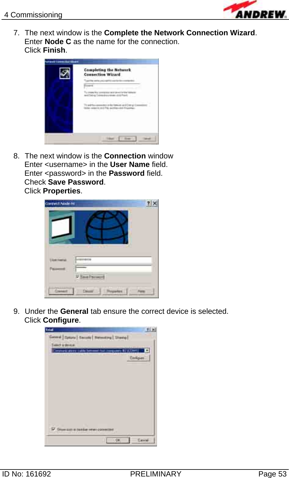
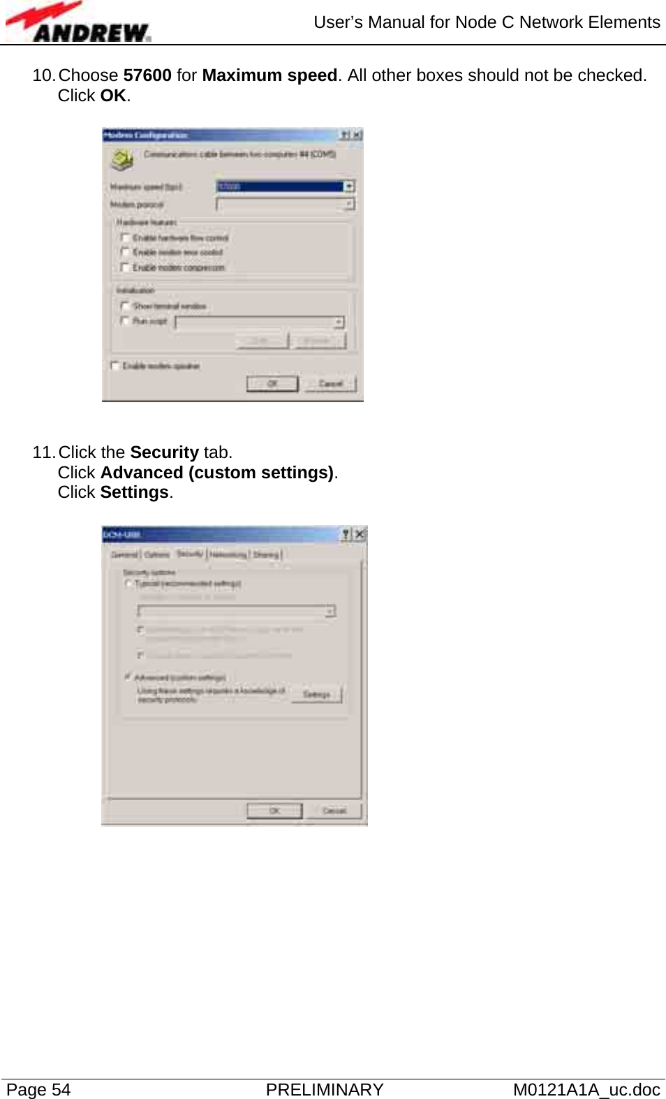
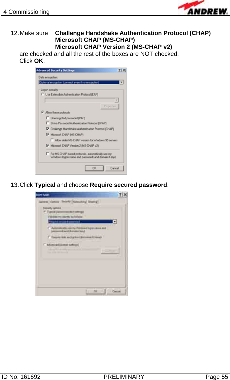
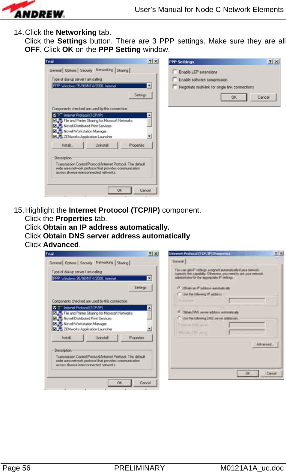
Users Manual
Navigation menu
Upload a User Manual
Namespaces
Wiki Guide
HTML
PDF
Info
Views
User Manual
Discussion / Help
Navigation

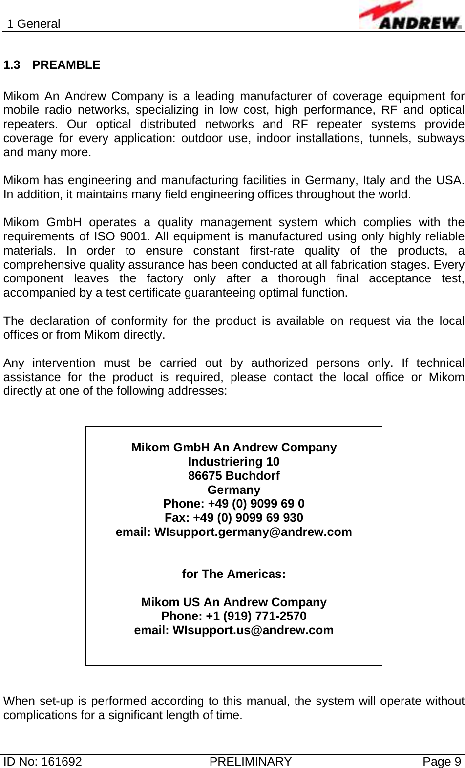
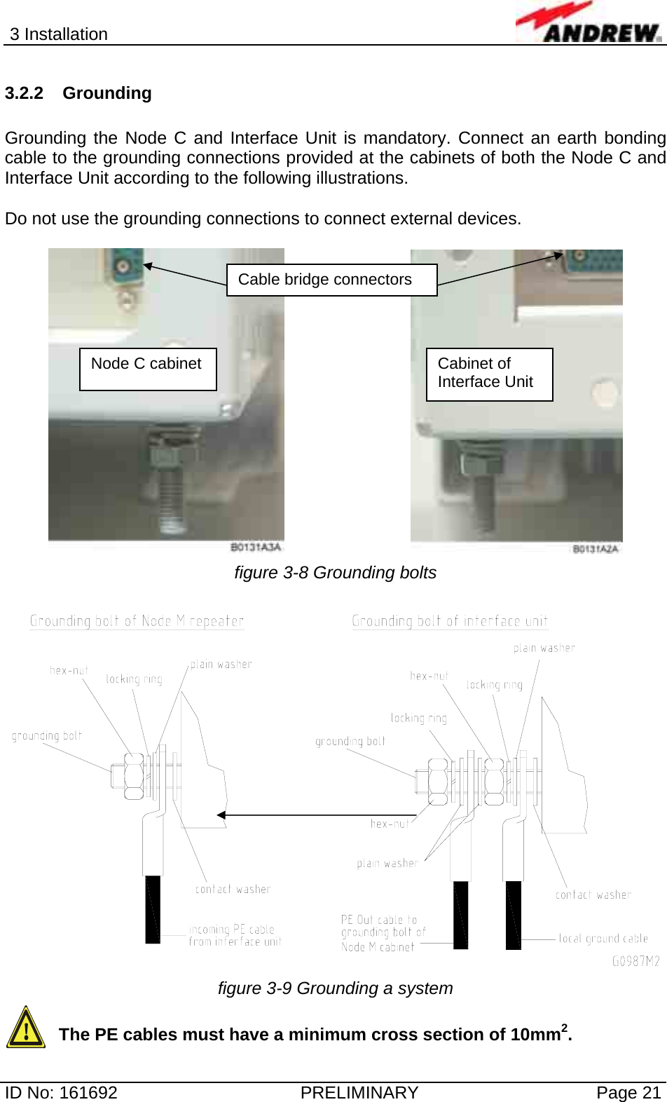
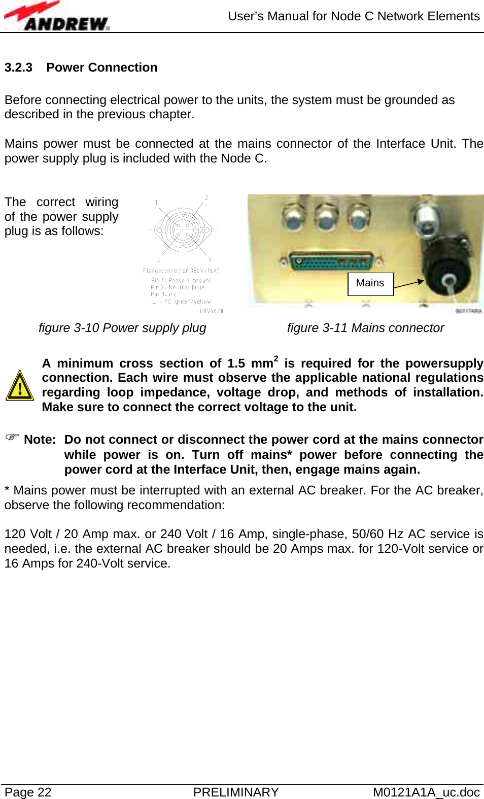
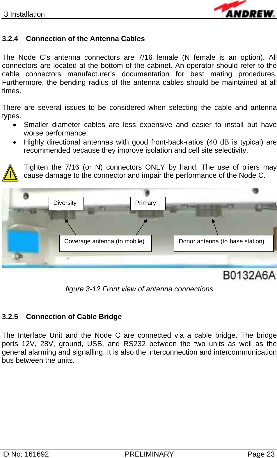
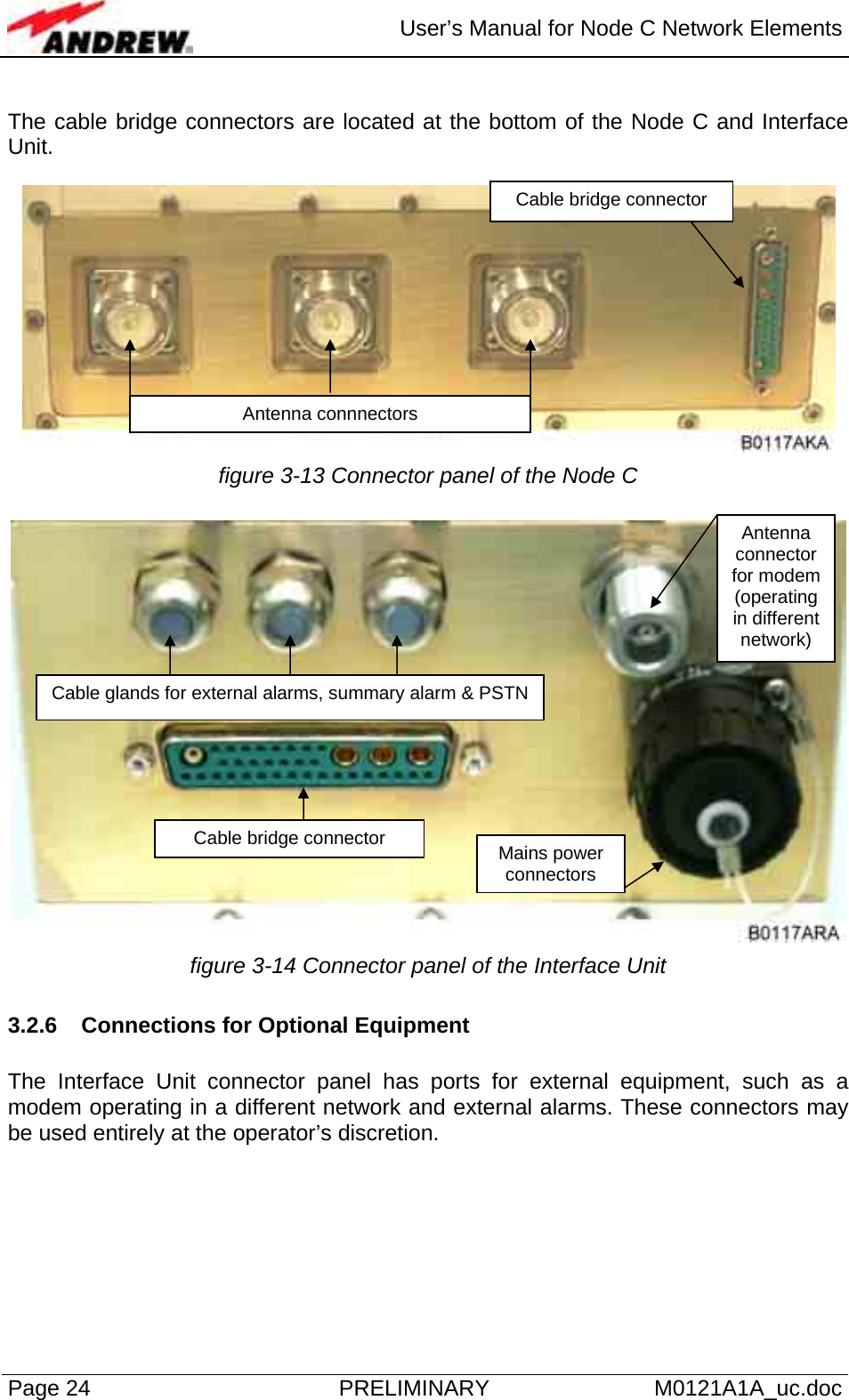
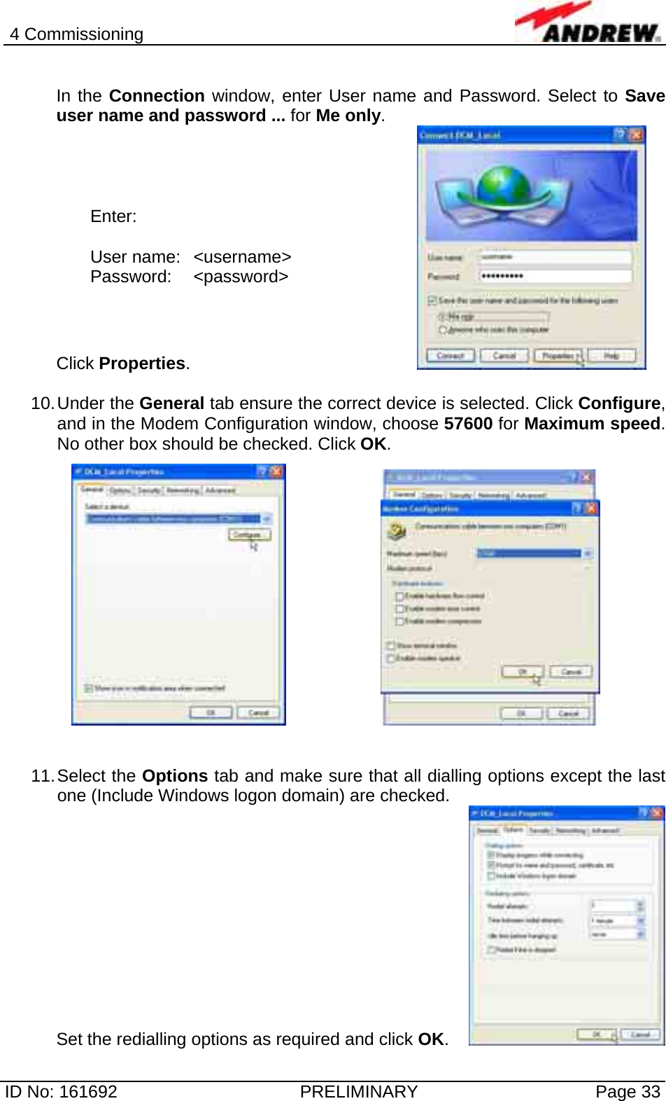
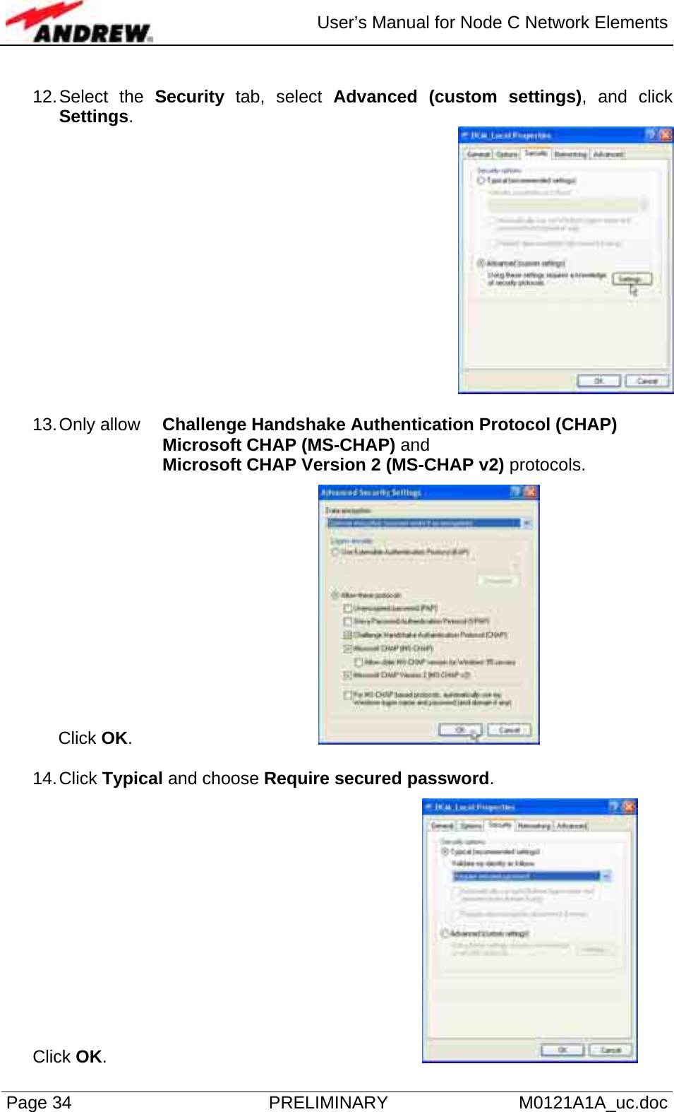
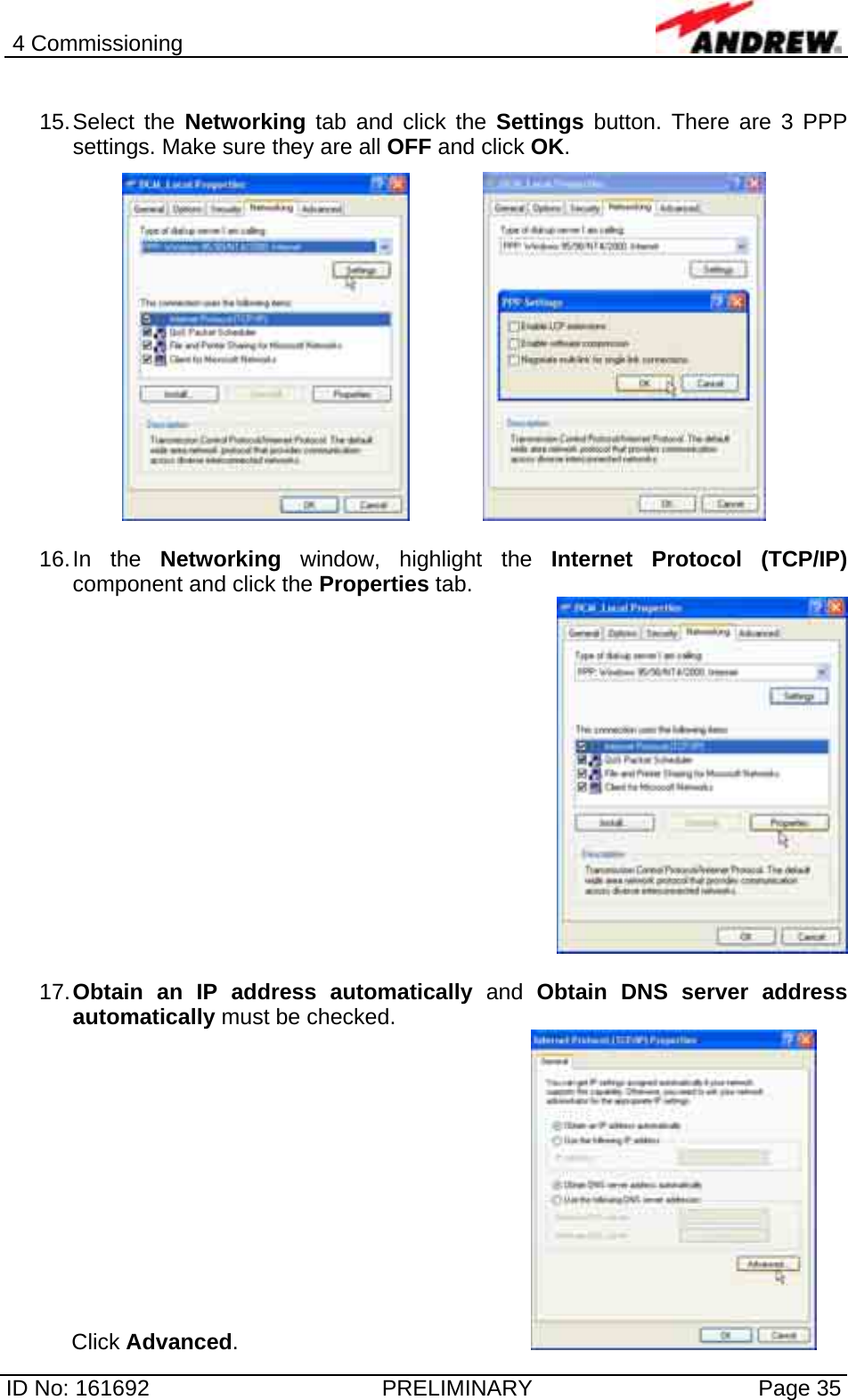
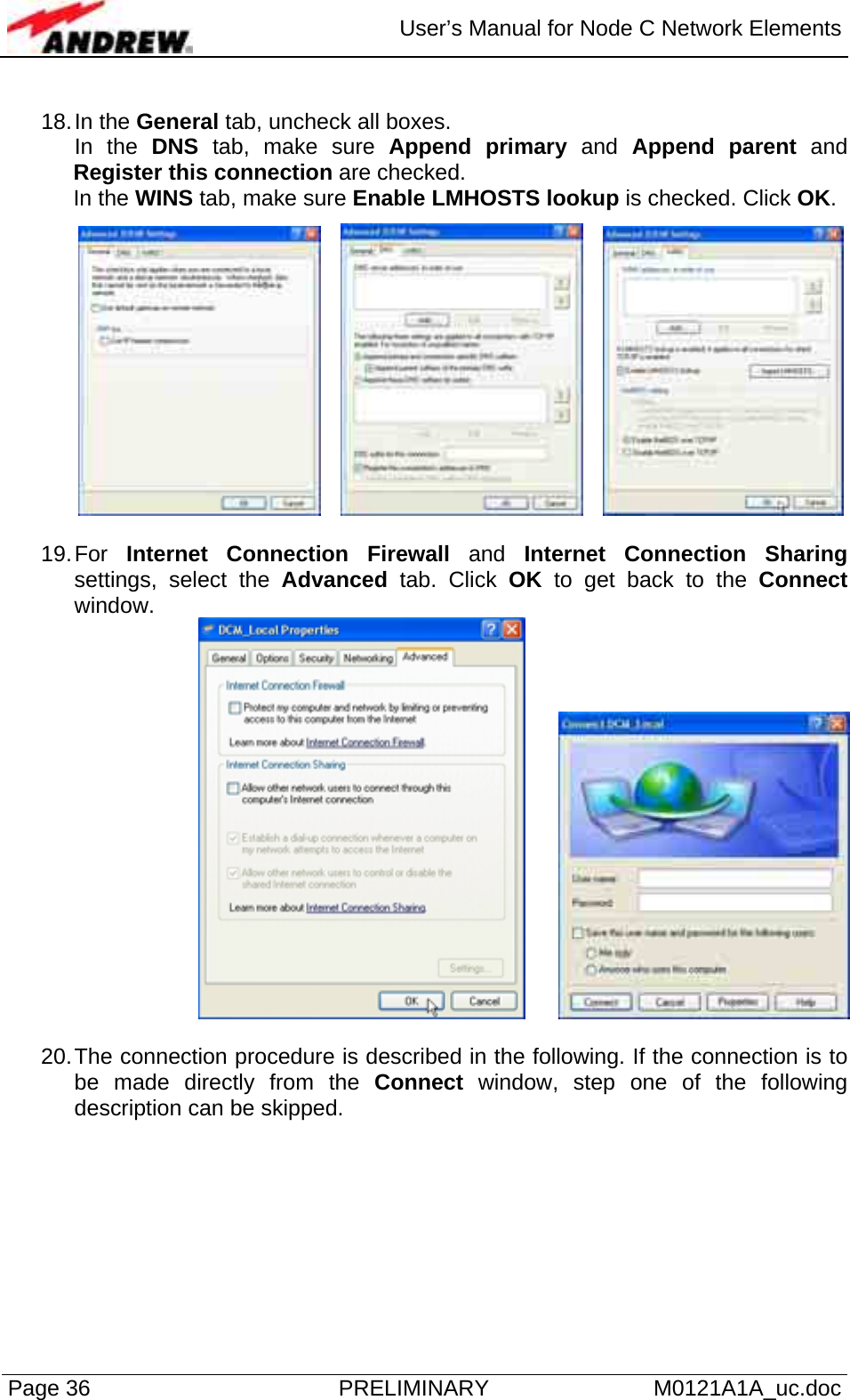
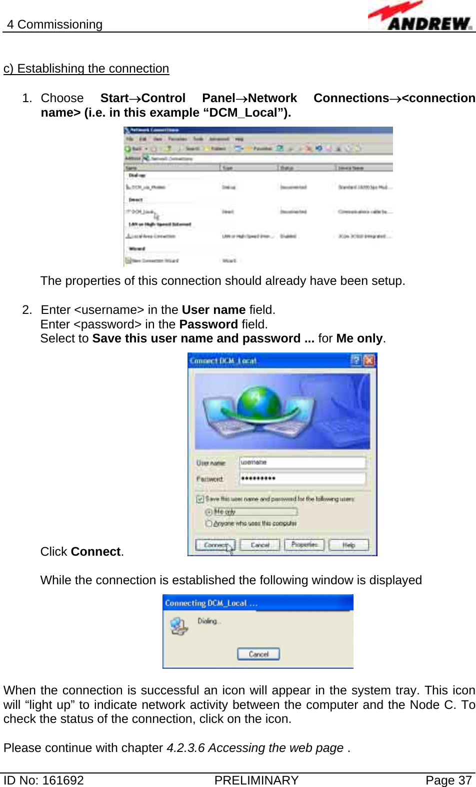
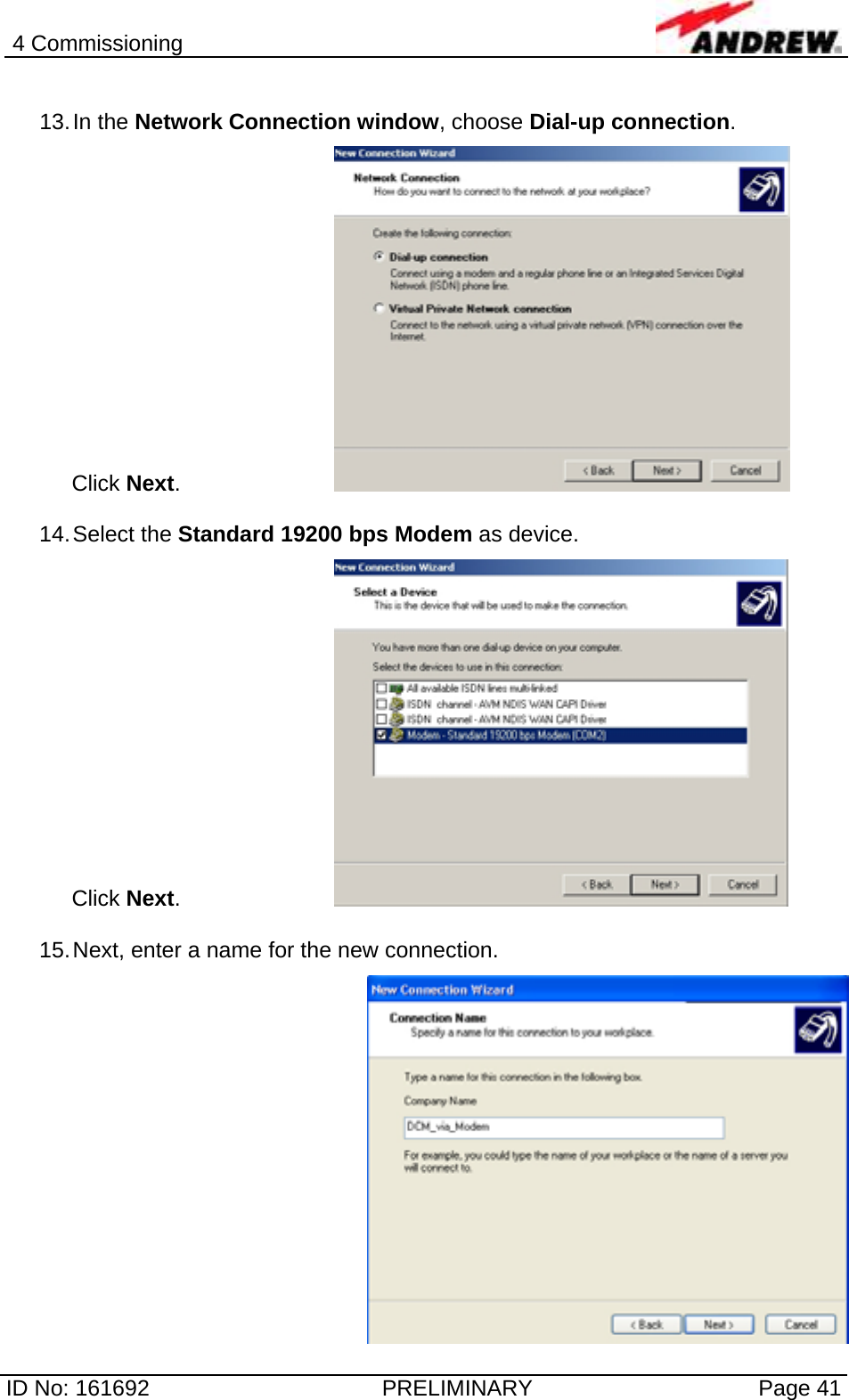
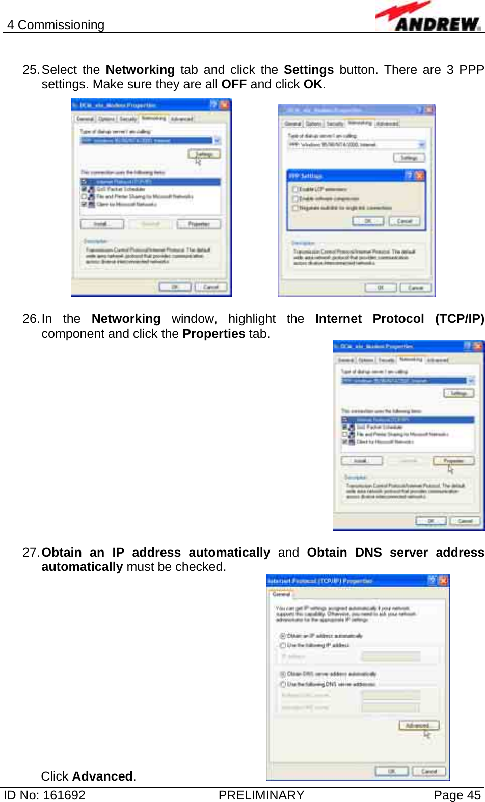
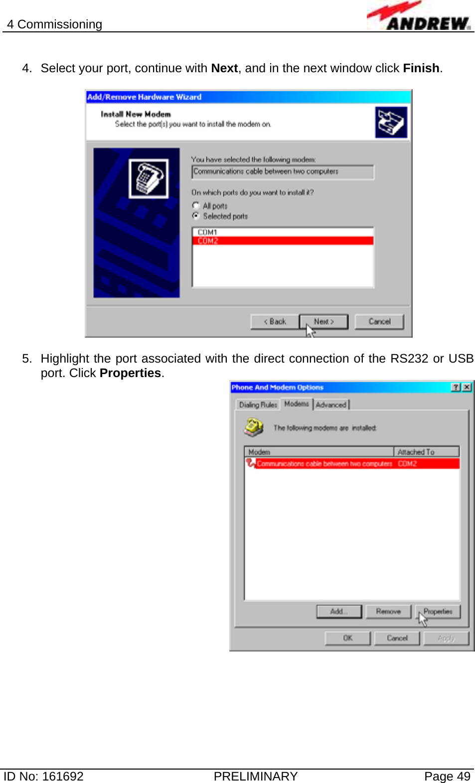
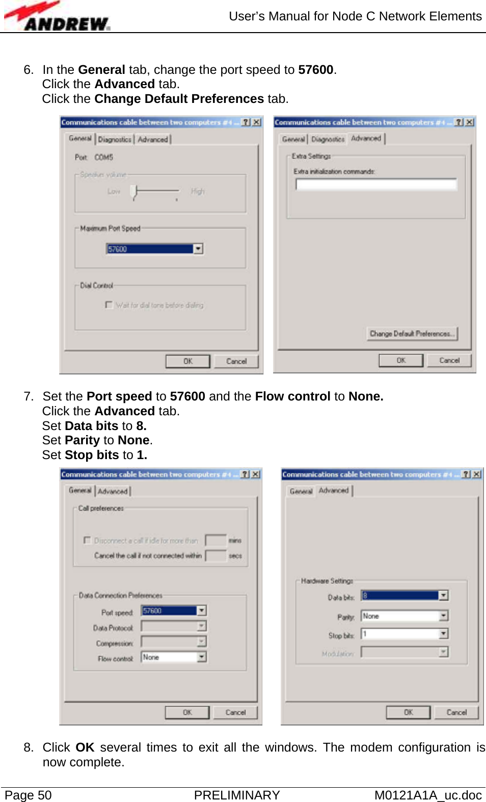
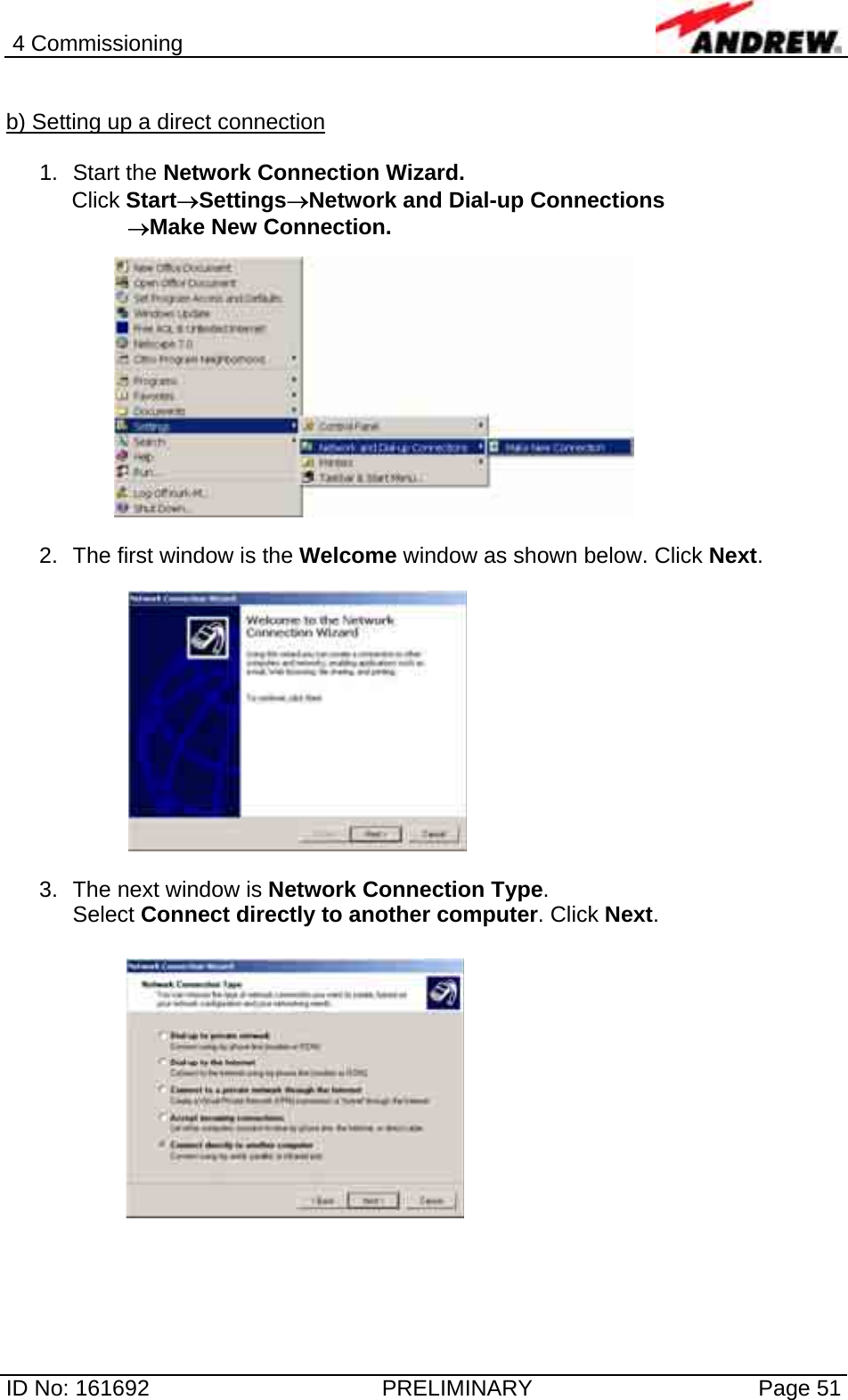
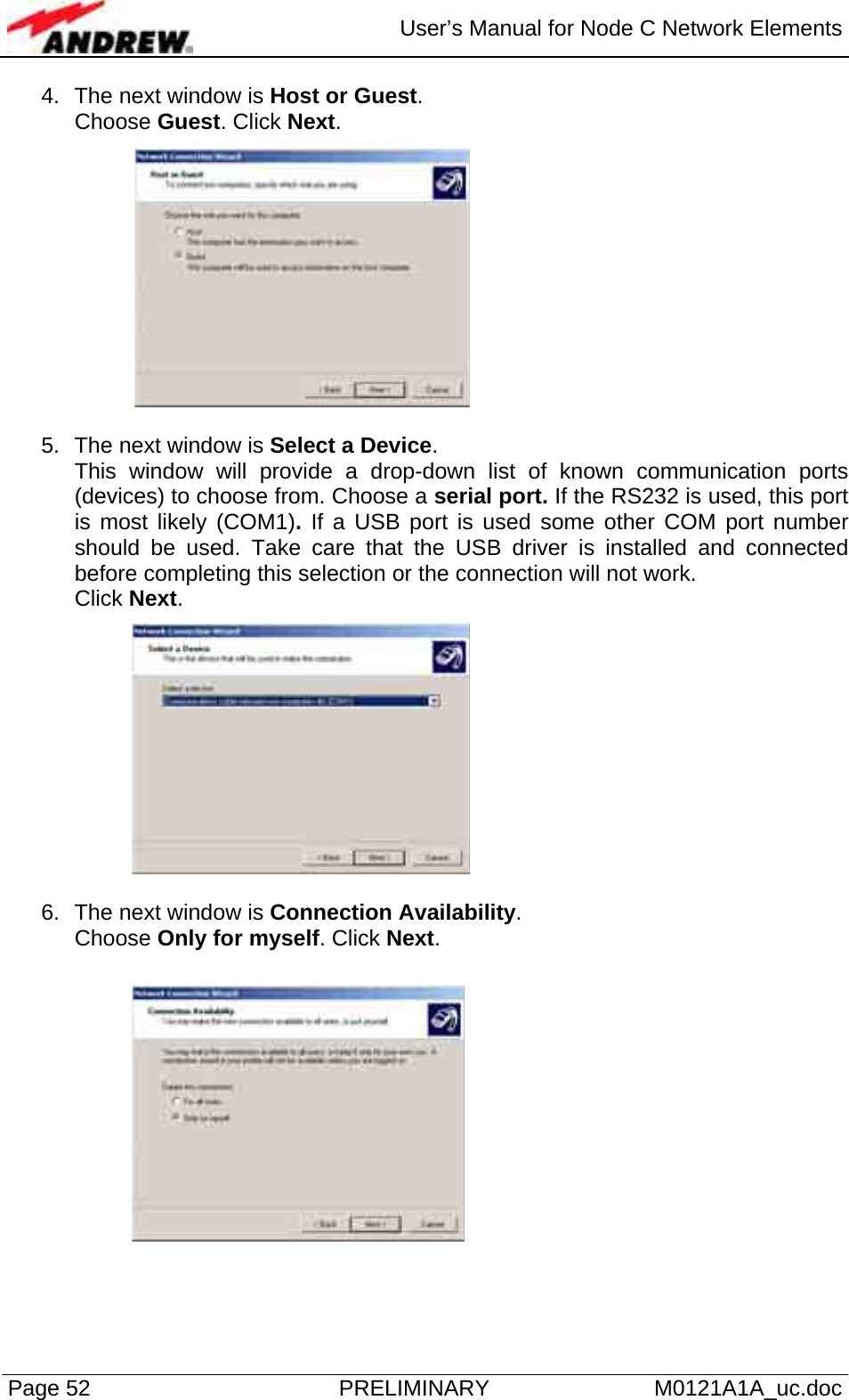
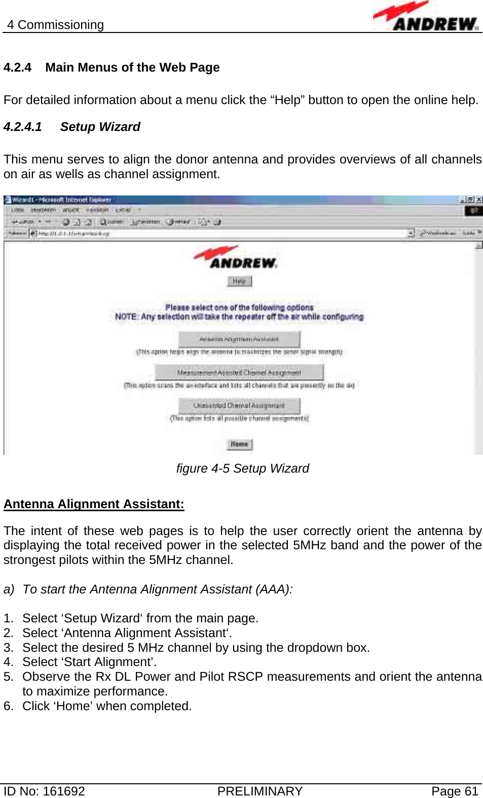
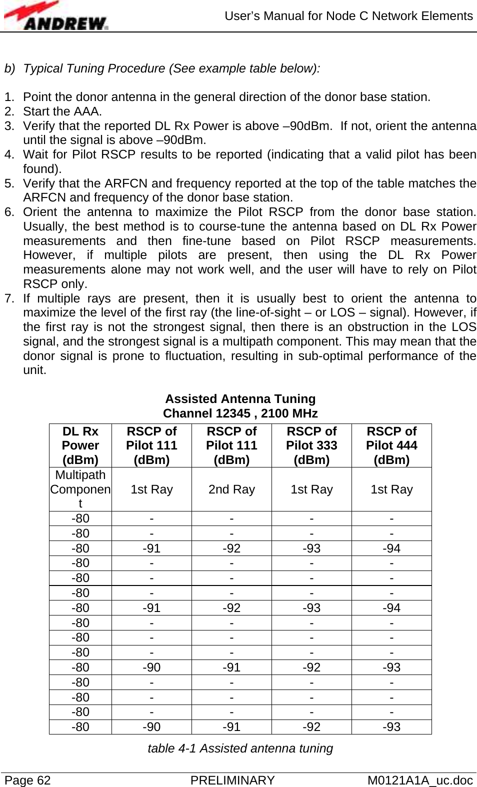
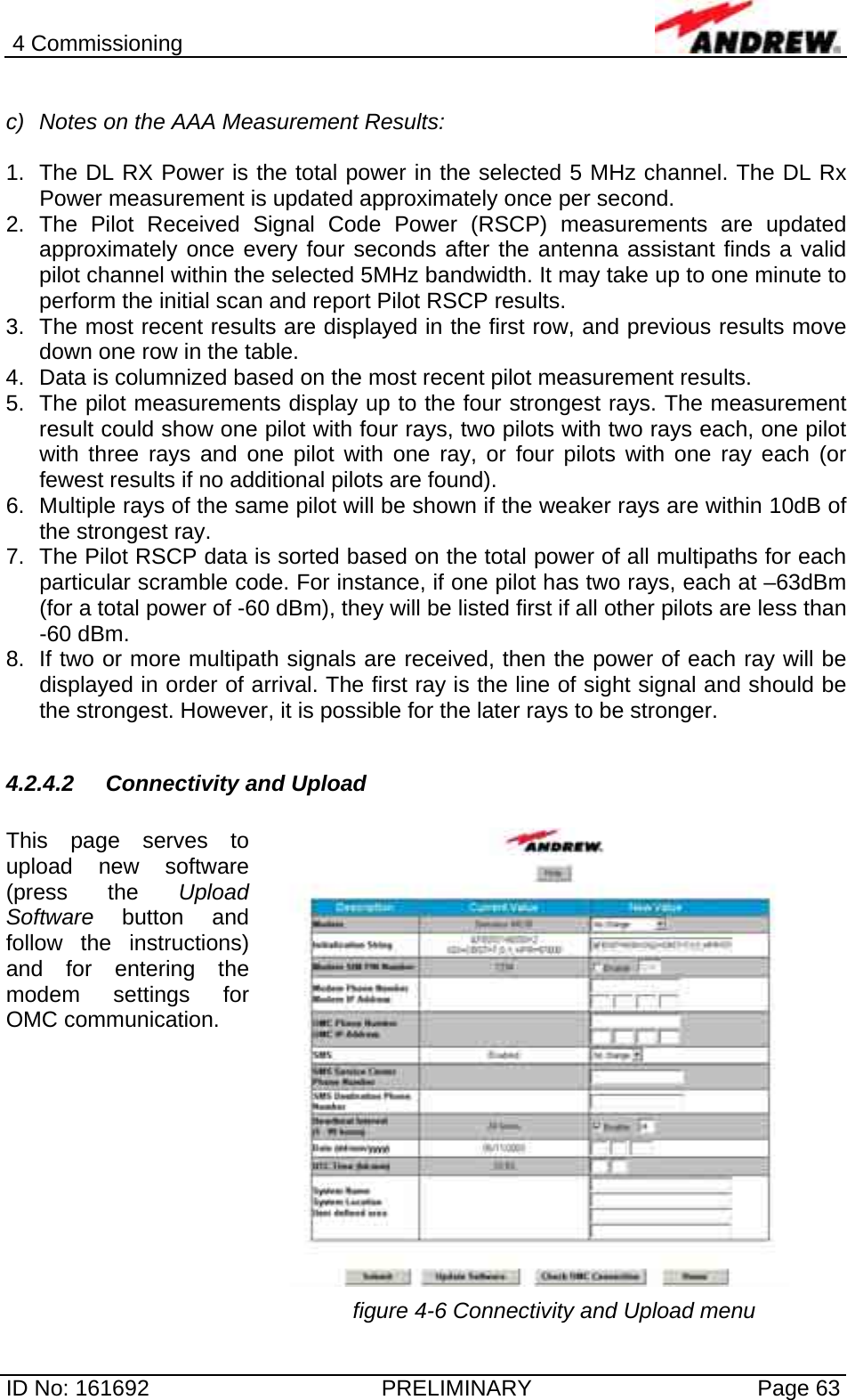
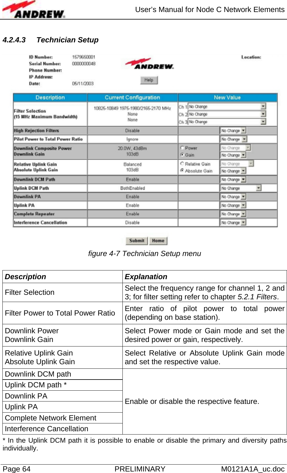
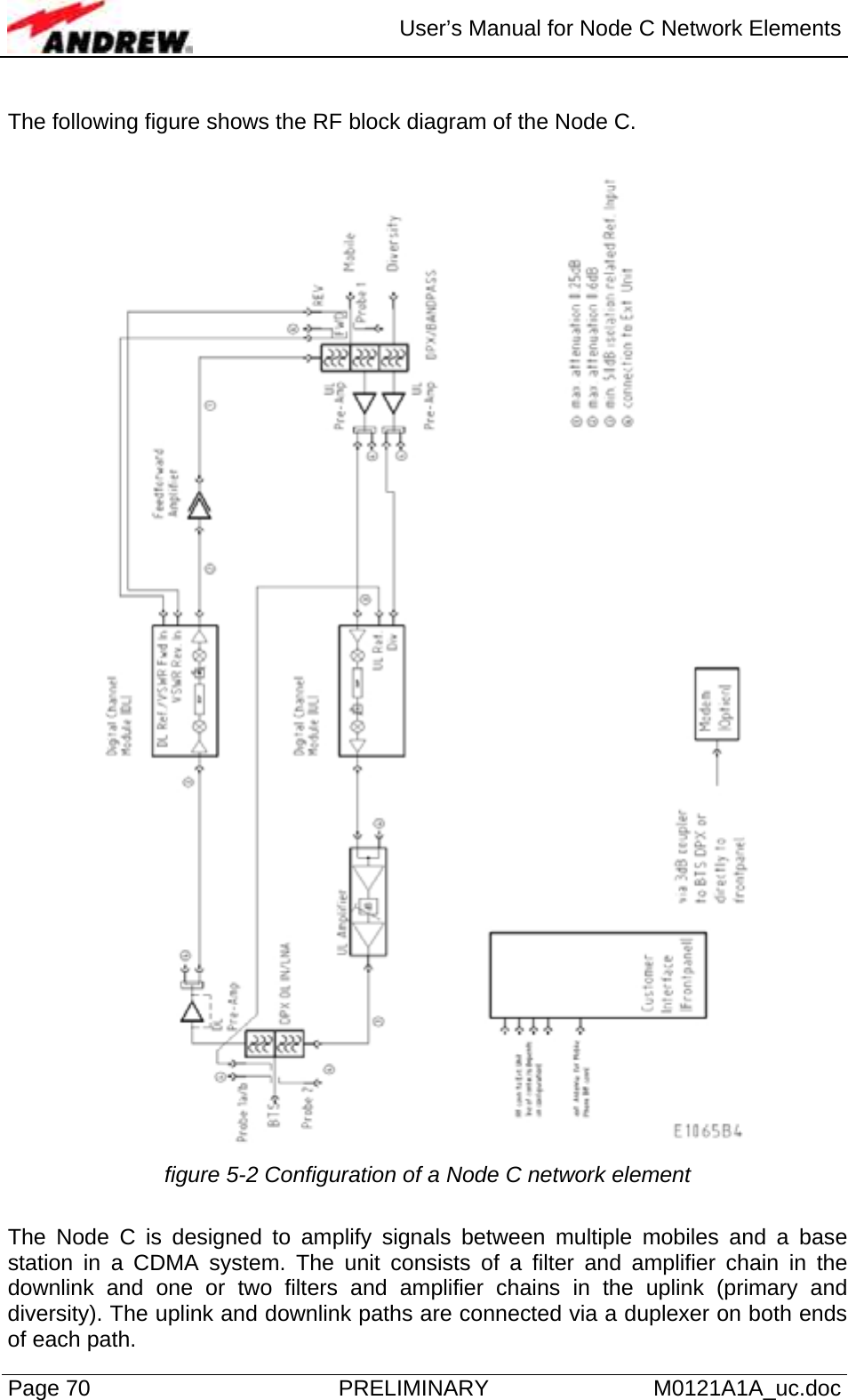
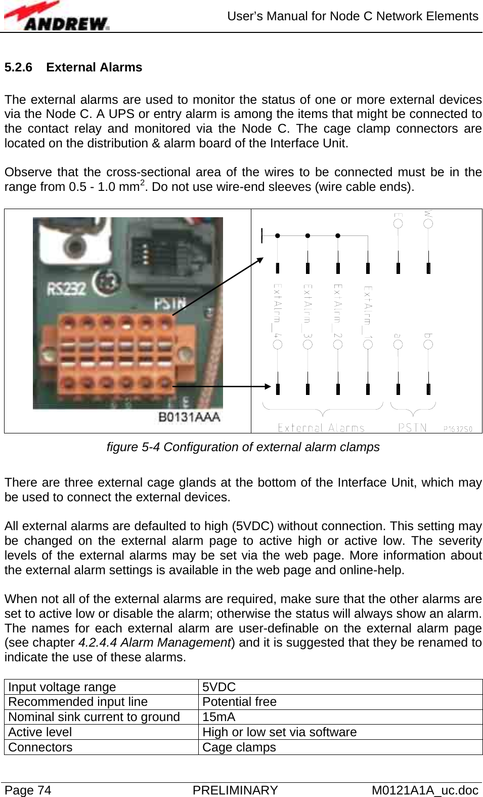
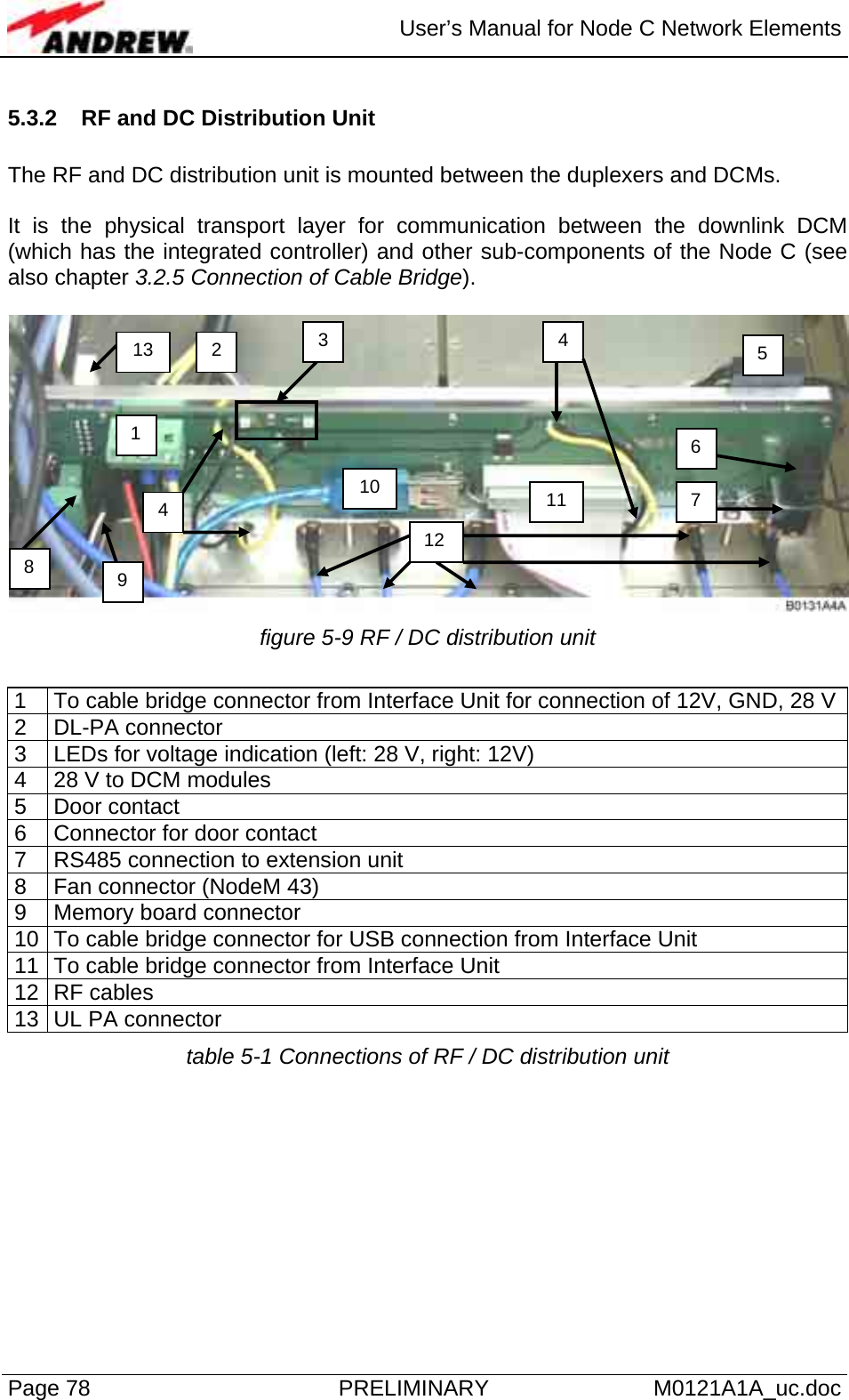
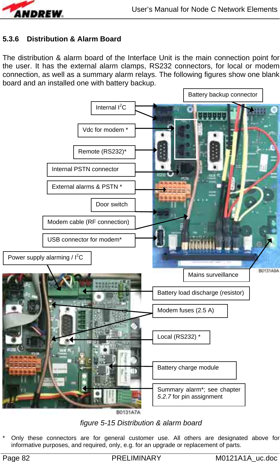
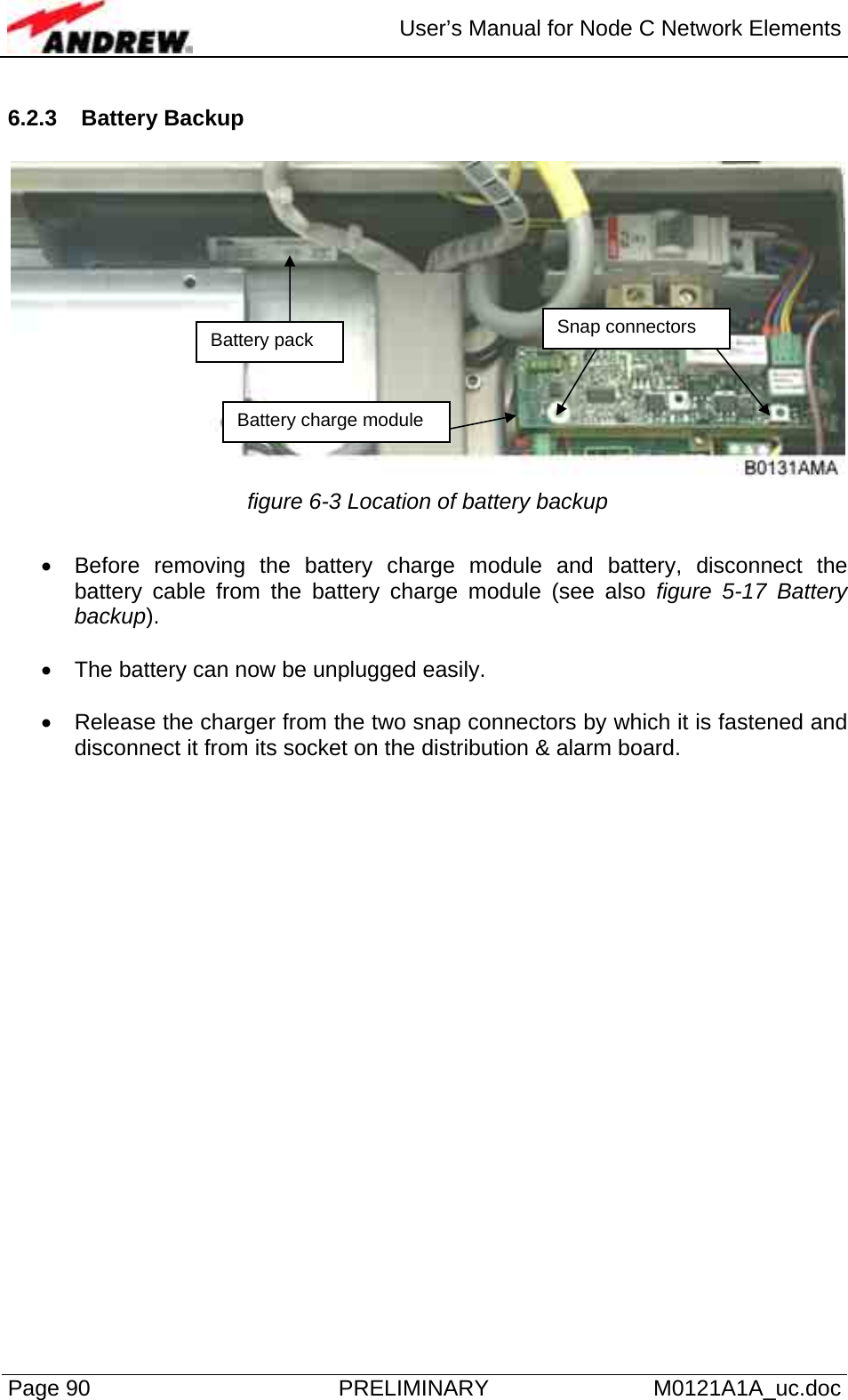
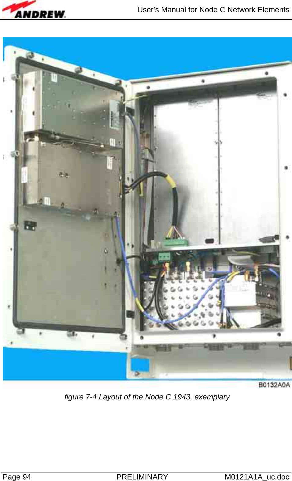
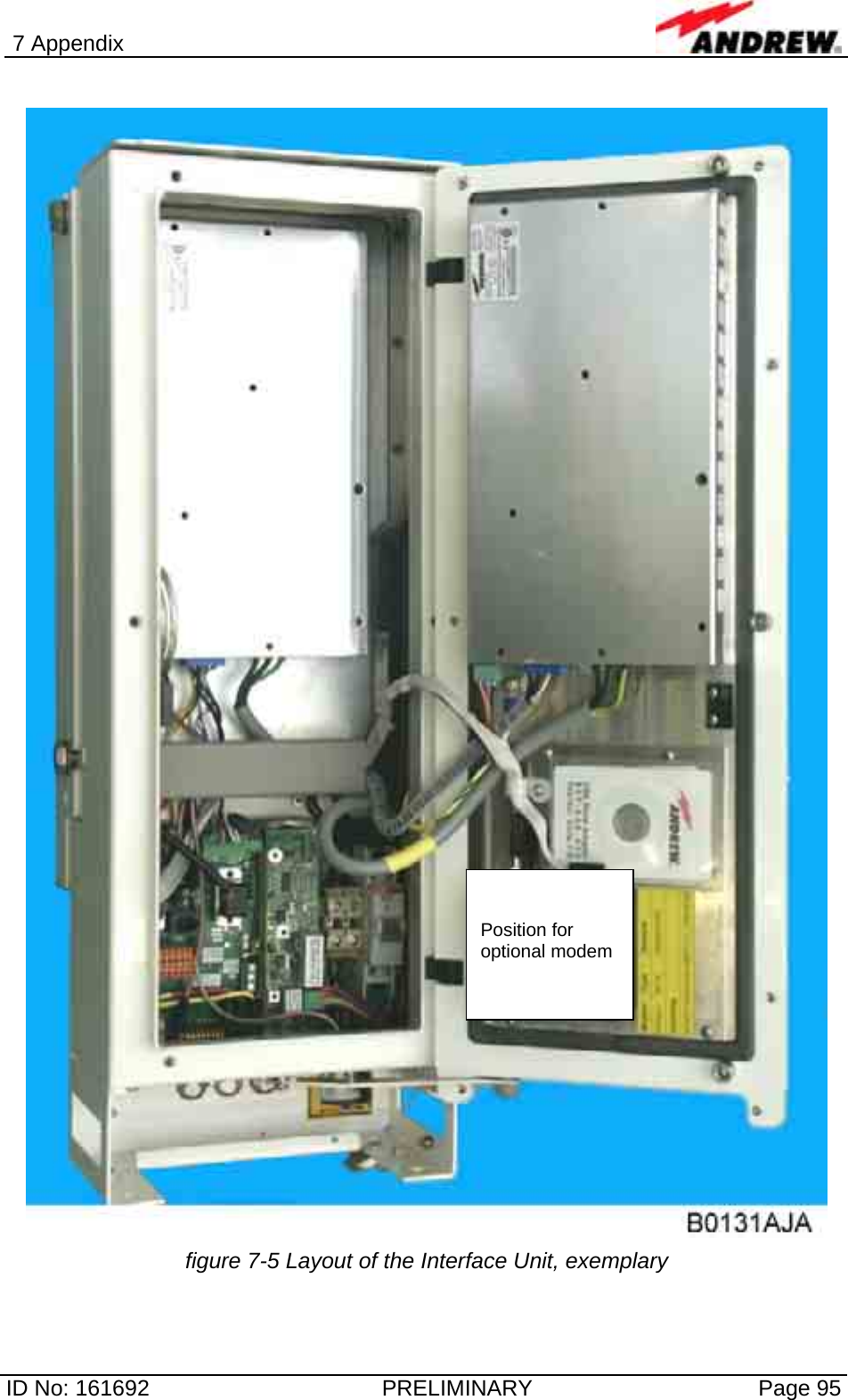
![4 Commissioning ID No: 161692 PRELIMINARY Page 65 4.2.4.4 Alarm Management figure 4-8 Alarm Management menu Column Description 1 ID Clicking any of the number buttons opens a submenu * for the respective component/feature. 2 Module All components and features listed in this column can be monitored via software. 3 Current Status The cell colour (see [4] below) indicates whether an alarm is active. If more alarms of different severity levels are active simultaneously (number of alarms is displayed in column “Alarm Count” to the right), the cell will always show the highest level that is active. 4 This row illustrates the colours by which the individual severity levels are represented in column 3. * This submenu includes an overview of the alarms available for the respective component/feature and alarms can be disabled. In the column “Alarm Group” the severity level for each alarm can be set. The possible severity levels are illustrated under [4]. In the submenu for “VSWR, ALC, RSSI” [7] it is also possible to set the alarm threshold (level at which an alarm will released) for these features. Use the submenu [8] for “External, Fan and Door” for naming the external alarms.](https://usermanual.wiki/Andrew-Wireless-Innovations-Group/RPT-NODEC1943/User-Guide-405789-Page-65.png)