Andrew Wireless Innovations Group RPT-NODEC1943 Broadband PCS Repeater User Manual M0121A1A uc
Andrew Wireless Innovations Group Broadband PCS Repeater M0121A1A uc
Users Manual
ID No: 161692 PRELIMINARY Page 1
User’s Manual
for
Node C Prototype
Network Elements
with Interface Unit

User’s Manual for Node C Network Elements
Page 2 PRELIMINARY M0121A1A_uc.doc
© Copyright 2003 Mikom GmbH
All rights reserved.
All information contained in this manual has been revised thoroughly. Yet Mikom An
Andrew Company accepts no liability for any omissions or faults.
Mikom An Andrew Company reserves the right to change all hard- and software
characteristics without notice.
Names of products mentioned herein are used for identification purposes only and
may be trademarks and/or registered trademarks of their respective companies.
No parts of this publication may be reproduced, stored in a retrieval system,
transmitted in any form or by any means, electronical, mechanical photocopying,
recording or otherwise, without prior written permission of the publisher.
Mikom GmbH An Andrew Company, 27-November-2003

ID No: 161692 PRELIMINARY Page 3
TABLE OF CONTENTS
1 GENERAL 7
1.1 ABBREVIATIONS 7
1.2 HEALTH AND SAFETY WARNINGS 8
1.3 PREAMBLE 9
1.4 INTERNATIONAL CONTACT ADDRESSES 10
2 INTRODUCTION 11
2.1 PURPOSE 11
2.2 THE NODE C NETWORK ELEMENT 11
2.3 QUICK START CHECKLIST 12
3 INSTALLATION 13
3.1 MECHANICAL INSTALLATION 13
3.1.1 General 13
3.1.2 Wall Mounting Procedure 14
3.1.3 Connection Option 16
3.1.4 Pole Mounting Procedures 17
3.2 ELECTRICAL INSTALLATION 20
3.2.1 General 20
3.2.2 Grounding 21
3.2.3 Power Connection 22
3.2.4 Connection of the Antenna Cables 23
3.2.5 Connection of Cable Bridge 23
3.2.6 Connections for Optional Equipment 24
4 COMMISSIONING 25
4.1 GENERAL 25
4.2 SOFTWARE SETUP 26
4.2.1 Remote Control 26
4.2.2 Connection Devices 26
4.2.3 Connection Procedures 26
4.2.3.1 Setup Overview 26
4.2.3.2 Installing the USB driver 27
4.2.3.3 Direct connection for Windows XP 28
4.2.3.4 Modem connection for Windows XP 38
4.2.3.5 Direct connection for Windows 2000 48
4.2.3.6 Accessing the web page 60
4.2.4 Main Menus of the Web Page 61
4.2.4.1 Setup Wizard 61
4.2.4.2 Connectivity and Upload 63
4.2.4.3 Technician Setup 64
4.2.4.4 Alarm Management 65
4.3 TROUBLESHOOTING 66

User’s Manual for Node C Network Elements
Page 4 PRELIMINARY M0121A1A_uc.doc
5 FUNCTIONAL DESCRIPTION 69
5.1 GENERAL 69
5.2 FEATURES OF THE NODE C 72
5.2.1 Filters 72
5.2.2 Digital ICE (Digital Interference Cancellation Equipment) 72
5.2.3 VSWR (Voltage Standing Wave Ratio) 73
5.2.4 RSSI (Receive Signal Strength Indication) 73
5.2.5 Alarmforwarding 73
5.2.6 External Alarms 74
5.2.7 Summary Alarm 75
5.3 COMPONENTS OF THE NODE C AND INTERFACE UNIT 76
5.3.1 Duplexer 76
5.3.2 RF and DC Distribution Unit 78
5.3.3 Digital Channel Module (DCM) 79
5.3.4 Uplink Final Amplifier 80
5.3.5 Downlink Final Amplifier 80
5.3.6 Distribution & Alarm Board 82
5.3.7 Power Supply 83
5.4 OPTIONAL EQUIPMENT 83
5.4.1 Modem with Battery Backup 83
5.4.1.1 Initstrings 84
5.4.1.2 Wireless Modem 84
5.4.1.3 Battery Backup 85
5.4.2 PSU Redundancy 86
5.4.3 High Rejection Filter 86
6 MAINTENANCE 87
6.1 GENERAL 87
6.2 REPLACEMENT OF COMPONENTS 87
6.2.1 Power Supply 88
6.2.2 Modem 89
6.2.3 Battery Backup 90
7 APPENDIX 91
7.1 ILLUSTRATIONS 91
7.1.1 Cabinet Drawings 91
7.1.2 Layout 93
7.2 SPECIFICATIONS 96
7.2.1 Electrical Specifications 96
7.2.2 Mechanical Specifications 98
7.2.3 Specifications for Optional Equipment 98
7.3 PARTSLISTS 99
7.3.1 Interface Unit 99
7.3.2 Node C 100
8 INDEX 101

ID No: 161692 PRELIMINARY Page 5
FIGURES AND TABLES
figure 3-1 Positions of drilling holes.......................................................................... 14
figure 3-2 Wall mounting procedure.......................................................................... 15
figure 3-3 Connection option..................................................................................... 16
figure 3-4 Cabinet combining kit ............................................................................... 16
figure 3-5 Pole mounted systems ............................................................................. 17
figure 3-6 Back-to-back pole mounting ..................................................................... 18
figure 3-7 Pole mounting two systems...................................................................... 19
figure 3-8 Grounding bolts ........................................................................................ 21
figure 3-9 Grounding a system ................................................................................. 21
figure 3-10 Power supply plug .................................................................................. 22
figure 3-11 Mains connector ..................................................................................... 22
figure 3-12 Front view of antenna connections......................................................... 23
figure 3-13 Connector panel of the Node C .............................................................. 24
figure 3-14 Connector panel of the Interface Unit..................................................... 24
figure 4-1 Front and top cover screws ...................................................................... 25
figure 4-2 Position of mains power switch................................................................. 25
figure 4-3 USB and null modem cable connection.................................................... 27
figure 4-4 Home page of web interface..................................................................... 60
figure 4-5 Setup Wizard............................................................................................ 61
figure 4-6 Connectivity and Upload menu................................................................. 63
figure 4-7 Technician Setup menu............................................................................ 64
figure 4-8 Alarm Management menu ........................................................................ 65
figure 5-1 DC block diagram of a Node C................................................................. 69
figure 5-2 Configuration of a Node C network element............................................. 70
figure 5-3 RF path of a Node C, exemplary .............................................................. 71
figure 5-4 Configuration of external alarm clamps .................................................... 74
figure 5-5 Summary alarm relay ............................................................................... 75
figure 5-6 Layout of a Node C 1943 and Interface Unit ............................................ 76
figure 5-7 Duplexer, DL IN........................................................................................ 77
figure 5-8 Duplexer, UL IN, with integrated diversity filter......................................... 77
figure 5-9 RF / DC distribution unit ........................................................................... 78
figure 5-10 DCM (UL or DL part) .............................................................................. 79
figure 5-11 Uplink final amplifier ............................................................................... 80
figure 5-12 Node C x37 DL final amplifier................................................................. 80
figure 5-13 Node C x43 DL final amplifier, new type................................................. 81
figure 5-14 Node C x43 DL final amplifier, former version........................................ 81
figure 5-15 Distribution & alarm board...................................................................... 82
figure 5-16 Power supply.......................................................................................... 83
figure 5-17 Battery backup module, exemplary ........................................................ 85
figure 6-1 Power supply screws................................................................................ 88
figure 6-2 Mounting plate of modem......................................................................... 89
figure 6-3 Location of battery backup ....................................................................... 90
figure 7-1 Cabinet of a Node C................................................................................. 91
figure 7-2 Cabinet of a Node C Interface Unit........................................................... 92
figure 7-3 Layout of the Node C 1937, exemplary .................................................... 93
figure 7-4 Layout of the Node C 1943, exemplary .................................................... 94
figure 7-5 Layout of the Interface Unit, exemplary.................................................... 95

User’s Manual for Node C Network Elements
Page 6 PRELIMINARY M0121A1A_uc.doc
table 1-1 List of international contact addresses....................................................... 10
table 3-1 Mounting distance...................................................................................... 14
table 3-2 Required length of thread-bolts and cable bridge ...................................... 17
table 3-3 Components of pole mounting kits............................................................. 18
table 4-1 Assisted antenna tuning ............................................................................ 62
table 5-1 Connections of RF / DC distribution unit.................................................... 78
table 5-2 Standard initstring for modem.................................................................... 84
table 6-1 Specified torques for various screw types ................................................. 88

1 General
ID No: 161692 PRELIMINARY Page 7
1 GENERAL
1.1 ABBREVIATIONS
A/D Analogue to Digital Converter
ALC Automatic Level Control
ARFCN Absolute Radio Frequency Channel Number
BITE Built In Test Equipment
BTS Base Transceiver Station
CDMA Code Division Multiple Access
CF Center Frequency
CFO Center Frequency Offset
D/A Digital to Analogue Converter
D-ICE Digital Interference Cancellation
DCM Digital Channel Module
DL Downlink
DSP Digital Signal Processor
EMIF External Memory Interface
ESB Embedded System Block
ESD Electrostatic Discharge
ETSI European Telecommunication Standards Institute
FPGA Field Programmable Gate Array
FRU Field Replaceable Unit
I2C Bus Inter Integrated Circuit Bus (Philips)
ICE Interference Cancellation Equipment
ID No Identification Number
IF Intermediate Frequency
LE Logic Elements
LMT Local Maintenance Terminal
LVPECL Low Voltage Positive Emitter Coupled Logic
MSPS Mega Samples Per Second
NCO Numerically Controlled Oscillator
OMC Operation and Maintenance Centre
PCMCIA Personal Computer Modem Communication International Association
PLL Phase Lock Loop
PSTN Public Switched Telephone Network
RF Radio Frequency
RLP Radio Link Protocol
RSCP Received Signal Code Power
RSSI Receive Signal Strength Indication
RTC Real Time Clock
RX Receiver
SCL Serial Clock
SDA Serial Data
SMS Short Message Service
TS Transmitter
UL Uplink
UMTS Universal Mobile Telecommunication System
UPS Uninterruptable Power Supply
VSWR Voltage Standing Wave Ratio
WCDMA Wide-band Code Division Multiple Access

User’s Manual for Node C Network Elements
Page 8 PRELIMINARY M0121A1A_uc.doc
1.2 HEALTH AND SAFETY WARNINGS
1. Only suitably qualified personnel is allowed to work on this unit and only after
becoming familiar with all safety notices, installation, operation and maintenance
procedures contained in this manual.
2. Read and obey all the warning labels attached to the unit. Make sure that the
warning labels are kept in a legible condition and replace any missing or
damaged labels.
3. Obey all general and regional installation and safety regulations relating to work
on high voltage installations, as well as regulations covering correct use of tools
and personal protective equipment.
4. Keep operating instructions within easy reach and make them available to all
users.
5. It is the responsibility of the network provider to implement prevention measures
to avoid health hazards which may be associated to radiation from the antenna(s)
connected to the unit.
6. Make sure, access is restricted to qualified personnel.
7. Use this equipment only for the purpose specified by the manufacturer. Do not
carry out any modifications or fit any spare parts which are not sold or
recommended by the manufacturer. This could cause fires, electric shock or other
injuries.
8. Due to power dissipation, the network element may reach a very high
temperature.
9. Before opening the unit, disconnect mains.
10. ESD precautions must be observed! Before commencing maintenance work, use
the available grounding system to connect ESD protection measures.
11. This unit complies with European standard EN60950.
12. Make sure the network element settings are according to the intended use (see
also product information of manufacturer) and regulatory requirements are met.
13. Although the network element is internally protected against overvoltage, it is
strongly recommended to earth the antenna cables close to the network
element’s antenna connectors for protection against atmospheric discharge.

1 General
ID No: 161692 PRELIMINARY Page 9
1.3 PREAMBLE
Mikom An Andrew Company is a leading manufacturer of coverage equipment for
mobile radio networks, specializing in low cost, high performance, RF and optical
repeaters. Our optical distributed networks and RF repeater systems provide
coverage for every application: outdoor use, indoor installations, tunnels, subways
and many more.
Mikom has engineering and manufacturing facilities in Germany, Italy and the USA.
In addition, it maintains many field engineering offices throughout the world.
Mikom GmbH operates a quality management system which complies with the
requirements of ISO 9001. All equipment is manufactured using only highly reliable
materials. In order to ensure constant first-rate quality of the products, a
comprehensive quality assurance has been conducted at all fabrication stages. Every
component leaves the factory only after a thorough final acceptance test,
accompanied by a test certificate guaranteeing optimal function.
The declaration of conformity for the product is available on request via the local
offices or from Mikom directly.
Any intervention must be carried out by authorized persons only. If technical
assistance for the product is required, please contact the local office or Mikom
directly at one of the following addresses:
Mikom GmbH An Andrew Company
Industriering 10
86675 Buchdorf
Germany
Phone: +49 (0) 9099 69 0
Fax: +49 (0) 9099 69 930
email: WIsupport.germany@andrew.com
for The Americas:
Mikom US An Andrew Company
Phone: +1 (919) 771-2570
email: WIsupport.us@andrew.com
When set-up is performed according to this manual, the system will operate without
complications for a significant length of time.

User’s Manual for Node C Network Elements
Page 10 PRELIMINARY M0121A1A_uc.doc
1.4 INTERNATIONAL CONTACT ADDRESSES
in Australia
6 Stuart Street
Padstow NSW 2211
Australia
Phone: +61 (2) 9774-4200
Fax: +61 (2) 9774-4500
email:
WIsupport.australia@andrew.com
in France
Z.I. des Ebisoires
78370 Plaisir
France
Phone: +33 (1)30-79-15-36
Fax: +33 (1) 30-55-55-37
email:
WIsupport.france@andrew.com
in the USA
108 Rand Park Drive
Garner
NC 27529
USA
Phone: +1 (919) 771-2570
Fax: + 1 (919) 771-
email:
WIsupport.us@andrew.com
in the UK
Guildgate House
Pelican Lane
Newbury
RG14 1NX, Berkshire, U.K.
Phone: +44 (1635) 569-695
Fax: +44 (1635) 569-463
email:
WIsupport.uk@andrew.com
in China
Ground Floor, Unit F, Tower 2
The Astoria 198 Argle Street,
Mau Tau Wai, Kowloon
Hongkong
Phone: +852 2778 3187
Fax: +852 2778 3187
email:
WIsupport.china@andrew.com
in Canada
1815 Ironstone Manor, # 12
Pickering, Ontario L1W 3W9
Canada
Phone: +1 (905) 839-3474
Fax: +1 (905) 839-4663
email:
WIsupport.canada@andrew.com
in Switzerland
Tiergartenweg 1
4710 Balsthal
Switzerland
Phone: +41 (6238) 61260
Fax: +41 (6238) 61261
email:
WIsupport.switzerland@andrew.com
in Italy
Via De Crescenzi 40
48018 Faenza
Italy
Phone: +39 0546 697111
Fax: +39 0546 682768
email:
WIsupport.italia@andrew.com
in Austria
Weglgasse 10
2320 Schwechat
Austria
Phone: +43 (1) 706 – 3999
Fax: +43 (1) 706 – 39999
email:
WIsupport.austria@andrew.com
in Czech Republic
U Morusi 888
530 06 Pardubice-Svitkov
Czech. Republic
Phone: +42 (0406) 301280
Fax: +42 (0406) 301298
email:
WIsupport.czechrep@andrew.com
table 1-1 List of international contact addresses

2 Introduction
ID No: 161692 PRELIMINARY Page 11
2 INTRODUCTION
2.1 PURPOSE
Wireless communication systems provide a two-way information transfer (voice and
data) between a base station and multiple mobiles within a given area.
Environmental variables such as physical structures both man-made (buildings) and
natural (mountains) attenuate signals in the transmission path, which reduce the
transport signal’s strength. This attenuation leads to a reduction in quality and data
rate and eventually prohibits the system’s use entirely. A Node C is specifically
designed to extend coverage, enhance quality, and increase air-interface capacity.
In the downlink (DL), the Node C picks up signals coming from the base station,
filters them, amplifies them, and retransmits them to the mobile. In the uplink (UL), it
picks up signals from the mobile, filters them, amplifies them, and retransmits them to
the base station. The Node C constantly monitors the quality of the signals passing
through it, while simultaneously electronically decreasing isolation requirements.
2.2 THE NODE C NETWORK ELEMENT
The Node C is a primary network element, capable of enhancing up to three adjacent
CDMA carriers in a CDMA system. Its primary function is to increase the signal
strength between multiple mobiles and a base station in areas where basic voice or
high-speed data transmission is not available. It may be used for basic coverage,
signal reinforcement, and cell shaping, which can increase a network’s coverage
area, data rate, and capacity.
The Node C is a dedicated CDMA device. However, several enhancers operating at
different frequencies and technologies may share the same hardware (cables and
antennas) via a crossband coupler. Within the CDMA frequency band, multiple
operators may use the same unit via additional modules, thus reducing cost, while
sharing the user interface and antennas.
The Node C may be set-up locally or remotely. A circuit switch or packet data modem
may be connected to an integrated controller. This provides the network
management system with on-demand, alarm generated, or heartbeat monitoring via
the always-connected packet features. The Node C has features and functions that
may be monitored and changed by the operators via a web-based browser remotely
or locally, or via the SNMP based OMC software platform. The graphical interface of
the Node C provides a setup menu including a setup wizard which allows both setup
and monitoring capability without any equipment required apart from a laptop or PC.
The Node C network element is self-diagnosing, self-adaptive, and virtually
maintenance-free.

User’s Manual for Node C Network Elements
Page 12 PRELIMINARY M0121A1A_uc.doc
2.3 QUICK START CHECKLIST
Read the health and safety warnings in chapter 1.2 Health and Safety Warnings.
Setting up the Node C is quick and easy. The following step-by-step procedure
provides a quick overview for a correct setup and optimization.
a. Required Equipment
• Node C
• donor antenna
• coverage antenna(s) or DAS
• coaxial feeder cable
• connectors
• laptop with connection and mains cable
b. Required Information
Make sure to have the following information at hand:
• important on-site conditions (e.g. base station location, mains supply, etc.)
• channels to be enhanced/amplified
• pilot
• pilot power to total power
c. Procedure
1. Install the donor and coverage antennas.
2. Install the feeder cable from the Node C to the antennas.
3. Install the Node C (see chapter 3 Installation).
4. Install the Interface Unit (see chapter 3 Installation).
5. Connect cables between the Interface Unit and the Node C (see chapter
3.2 Electrical Installation).
6. Connect power and the antenna feeder cables to the Node C.
7. Open the Interface Unit as described in chapter 4.1 General.
8. Setup the connection computer (see chapter 4.2 Software Setup) and
establish a connection to the Node C (see chapter 4.2.3 Connection
Procedures).
9. Login to the unit and follow the installation wizard option for easy
installation.
a. Optimize the donor antenna performance (see chapter 4.2.4.1
Setup Wizard).
b. Select the channels for enhancement.
c. Enter the desired output power in the downlink.
d. Enter the pilot power to total power ratio of the donor base
station.
e. Enter the relative uplink gain.
f. Setup the modem (if applicable) and enter data in the other user
fields.
10. The Node C setup is complete.
11. Open the “Save Configuration to Laptop” menu for record keeping
purposes.
12. Unplug the computer, close the Interface Unit and tighten all screws.

3 Installation
ID No: 161692 PRELIMINARY Page 13
3 INSTALLATION
3.1 MECHANICAL INSTALLATION
3.1.1 General
Read the health and safety warnings in chapter 1.2 Health and Safety Warnings.
1. Do not install the unit in a way or at a place where the specifications
outlined in the Environmental and Safety Specifications leaflet of the
manufacturer are not met.
2. It is recommended only to use the mounting hardware delivered by the
manufacturer. If different mounting hardware is used, the specifications
for stationary use of the unit must not be exceeded.
) Note: Exceeding the specified load limits may cause the loss of warranty.
3. The unit is considerably heavy. Make sure that a suitable mounting
surface is used. Ensure there is adequate manpower to handle the
weight of the system.
4. Due to power dissipation, the unit may reach a very high temperature.
Ensure sufficient airflow for ventilation. Above and below the units a
minimum distance of 300* mm to ceiling, floor, etc. has to be kept. This
distance must also be observed between two units if they are mounted
one above the other.
* This value does not apply to the distance between Interface Unit and Node C. The
distance required between the two cabinets is specified in table 3-1 Mounting distance.
If any different or additional mounting material is used, ensure that the mounting
remains as safe as the mounting designed by the manufacturer. Ensure that the
static and dynamic strengths are adequate for the environmental conditions of the
site. The mounting itself must not vibrate, swing or move in any way that might cause
damage to the unit.
) Note: Both the Node C and the Interface Unit are delivered with a pre-
mounted front cover. This cover is of vital importance for the
correct forced airflow (of Node C 43) and for passive cooling (of
Node C 37 and Interface Unit). Thus, do not operate the units
without cover.
User’s Manual for Node C Network Elements
Page 14 PRELIMINARY M0121A1A_uc.doc
3.1.2 Wall Mounting Procedure
• Check the wall mounting kit and the wall to determine their suitability.
• The maximum distance between the Node C and the Interface Unit depends on
the length of the cable bridge by which they will be connected (see table 3-1
Mounting distance). Thus, before marking the mounting positions, check the
length of the cable bridge and make sure to install the units at a suitable distance.
Mounting style: beside each other* one above the other**
Length of cable bridge: 500 mm 800 mm 2000 mm only 2000 mm possible
Maximum distance 140 mm 400 mm 1600 mm 1000 mm (min.=300 mm)
* Maximum distance is referring to distance between the cabinet sides
** It is recommended to install the Node C above the Interface Unit; max. distance is the distance
between top of lower and bottom of upper unit
table 3-1 Mounting distance
) Note: The following figures show units that are mounted beside each
other. To install one above the other proceed in the same way, also
observing the specified mounting distance from table 3-1.
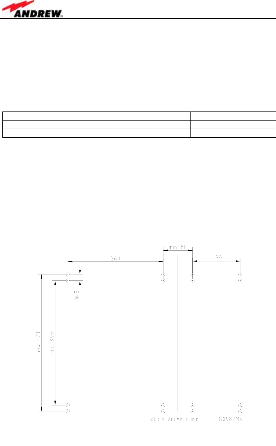
• Mark the position of the eight drilling holes (four per unit) for the Node C and
Interface Unit according to figure 3-1. Please observe that the figure always
shows a pair of drill holes for each position. Only drill one of each pair.
figure 3-1 Positions of drilling holes
3 Installation
ID No: 161692 PRELIMINARY Page 15
) Note: Ensure that there is free access to the electrical connections as well
as to the cabinet. The approved bending radius of the connected
cables must not be exceeded.
• Drill eight holes (four per unit) at the marked positions and insert dowels*.
* The dowels are not part of the delivery (and thus not illustrated in the figure) since the suitable type
depends on the on-site conditions (the material of wall). Therefore, use dowels that are appropriate
for the mounting surface.
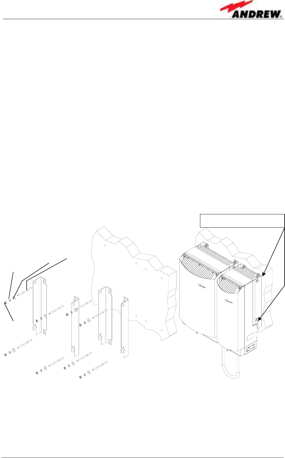
• Use a cap nut or locknut to screw the eight M8 dowel screws into the dowels.
• Use a hex wrench, opening 17 (old standard) or 16 (new standard), to loosen the
M10 hexagon head screws (four per unit) by which the mounting brackets are
fastened to the cabinet sides.
• Mount the mounting brackets to the screws, and fasten them using the M8
washers, locking rings, and hex nuts that are part of the wall mounting kit.
• Hang the cabinets into the brackets and fasten them with the M10 hexagon head
screws*.
figure 3-2 Wall mounting procedure
* If other screws than the ones delivered by the supplier are used for fastening, these must have a
diameter of at least 8 mm and an appropriate length (depending on the dowels). Additionally, make
sure they are adequate for supporting a maximum weight of 50 kg per unit.
For mounting both cabinets as one unit, a cabinet combining kit is available. The
according mounting procedure is explained in the following chapter.
M10 hexagon head screws
G0987Z0
Lockin
g
rin
g
M8
Plain washer M8 Dowel
screw
M8
Hex
nut
M8
User’s Manual for Node C Network Elements
Page 16 PRELIMINARY M0121A1A_uc.doc
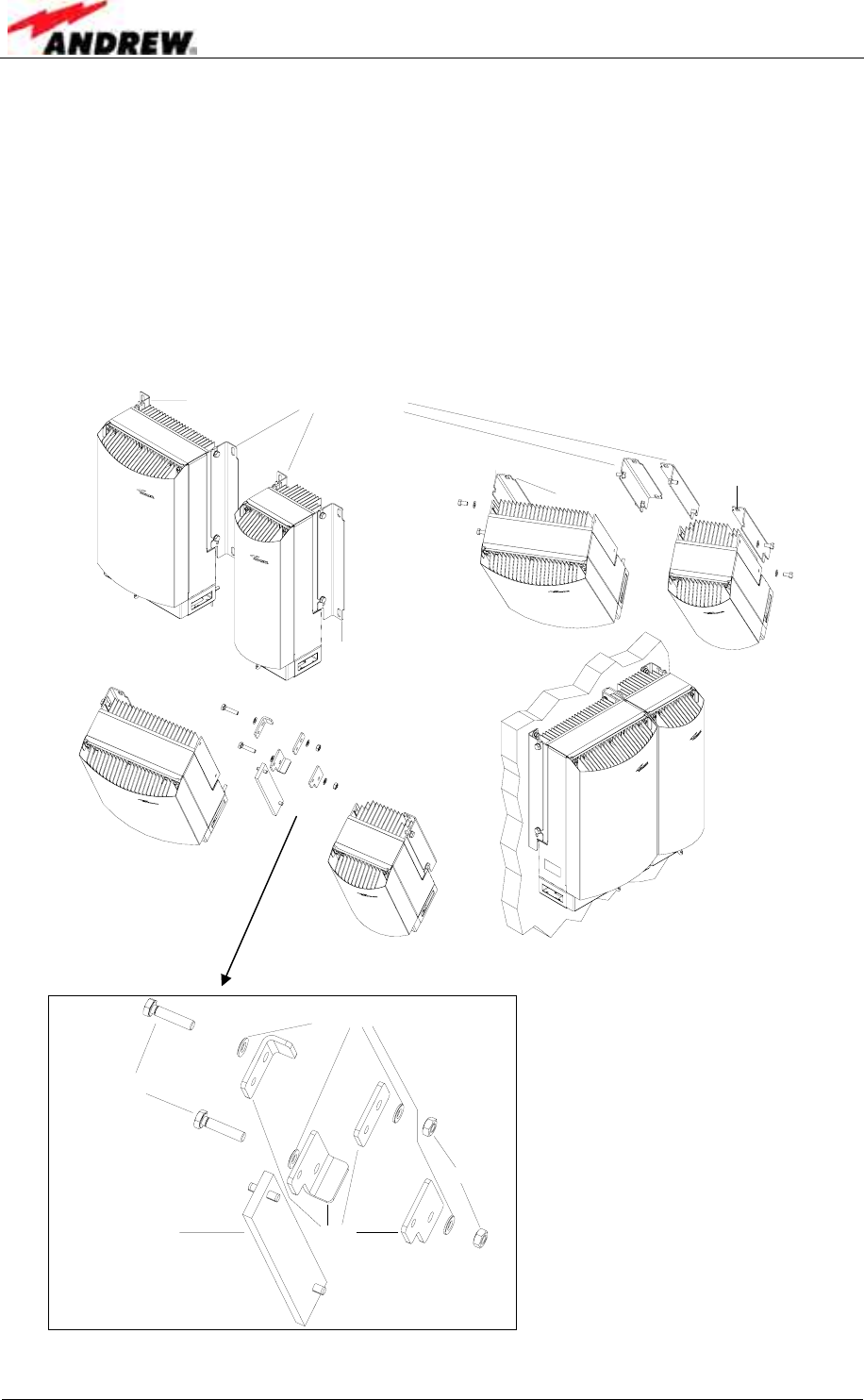
3.1.3 Connection Option
• In order to mount the system using the cabinet combining kit, dismount the
mounting brackets from the cabinets of the units by loosening the hexagon head
screws M10x20 by which the brackets are screwed to the housing (four per unit).
Do not unscrew those screws, only loosen them by approx. three turns and take
off the brackets.
• The two inner brackets are no longer required; exchange the outer brackets and
fasten them to the cabinets (as indicated below).
Remove and discard
1st step:
2nd step:
Bracket 1
Bracket 1
Bracket 2
Bracket 2
Exchange Bracket 1
and Bracket 2; then
mount as shown:
3rd step:
Join units and mount
joint system to wall
G0987MG
figure 3-3 Connection option
G0987MG
Washer DIN125
Hexagon head
screws M10x4
M10 nuts
BracketsConnecting plate
• Join the two cabinets using
the parts of the cabinet
combining kit as indicated.
• Use the special mounting
plan supplied as part of the
cabinet combining kit for
drilling the according holes
and mount the system to the
wall.
figure 3-4 Cabinet combining kit
3 Installation
ID No: 161692 PRELIMINARY Page 17
3.1.4 Pole Mounting Procedures
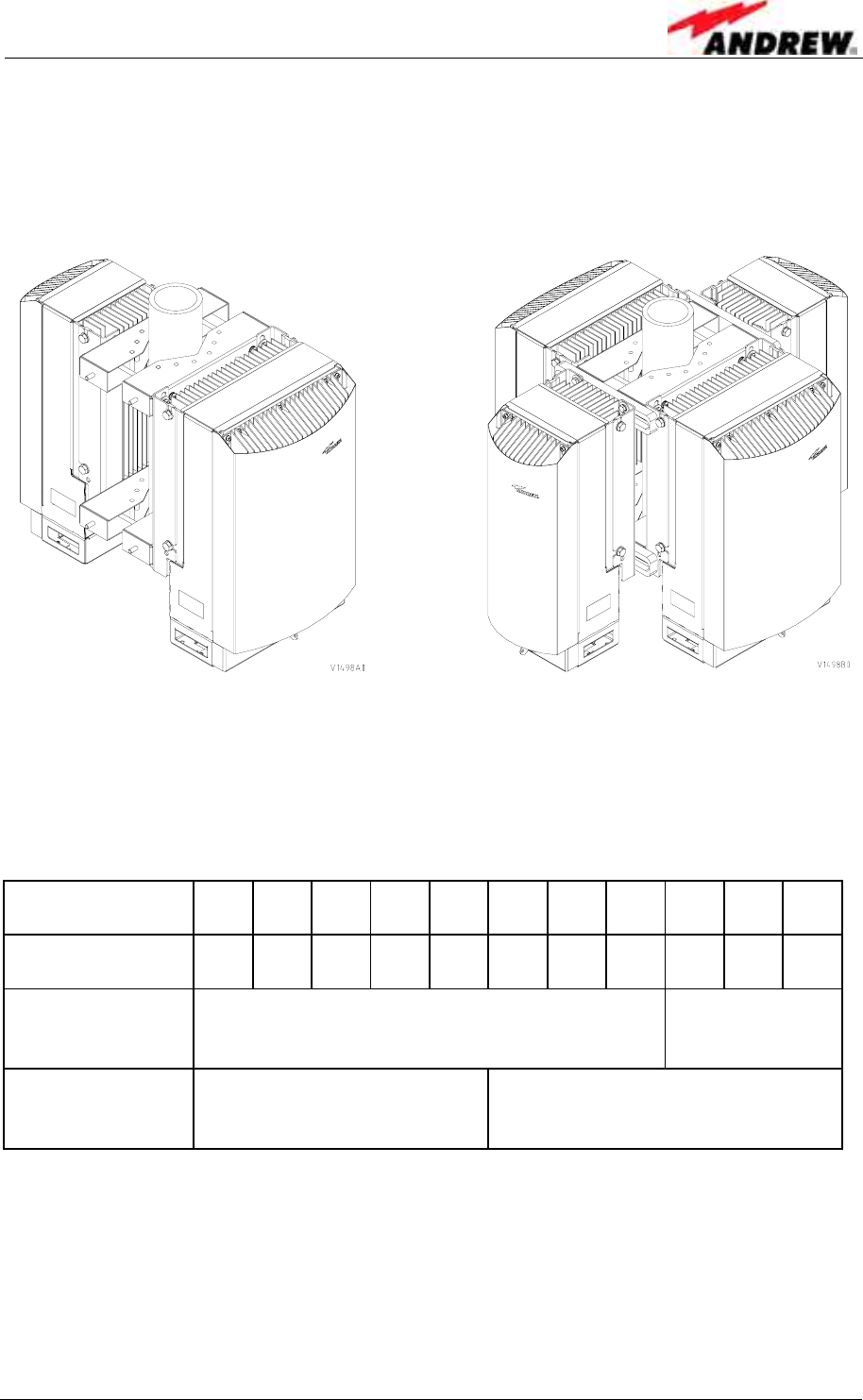
The following figure illustrates the two pole mounting options:
back-to-back (left) and two systems (right).
figure 3-5 Pole mounted systems
• Before starting the mounting procedure, check the pole diameter of the pole to
which the units will be installed; then, cut the thread-bolts (see table 3-3
Components of pole mounting kits, pos. 5) to the required length according to the
following table, which also states the appropriate cable bridge lengths:
Pole-diameter
(mm) 100 110 120 130 140 150 160 170 180 190 200
Length of Thread-
Bolt (mm) 216 226 236 246 256 266 276 286 296 306 317
Length of cable
bridge (mm)
(back-to-back) 800 2000
Length of cable
bridge (mm)
(for 2 systems) 800 2000
table 3-2 Required length of thread-bolts and cable bridge
User’s Manual for Node C Network Elements
Page 18 PRELIMINARY M0121A1A_uc.doc
Both types of pole mounting kit consist of the following parts (in different quantities):
No Part No Part
1 Pole mounting brace 5 Thread-bolt M8
2 Washer DIN 9021 – 8.4 6 Washer M8 DIN 125
3 Nut M8 DIN 934 7 Hexagon head screw M8
4 Spring ring DIN 127 – A8 8 Fastener
table 3-3 Components of pole mounting kits
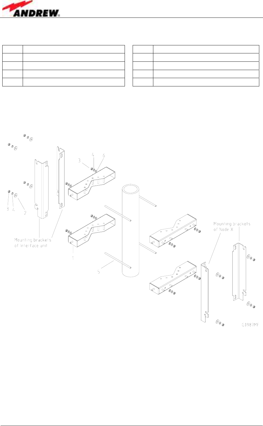
The numbers in the above table refer to the numbering of the components in the
following figures. Positions 7 and 8 are only required for mounting two systems.
figure 3-6 Back-to-back pole mounting
• Dismount the mounting brackets from the cabinets of the units by loosening the
hexagon head screws M10x20 by which the brackets are screwed to the housing
(four per unit). Do not unscrew those screws, only loosen them by approx. three
turns and take off the brackets.
• Fasten the mounting brackets to the pole using the corresponding mounting kit as
illustrated in figure 3-7 Pole mounting two systems or figure 3-6 Back-to-back pole
mounting, respectively.
3 Installation
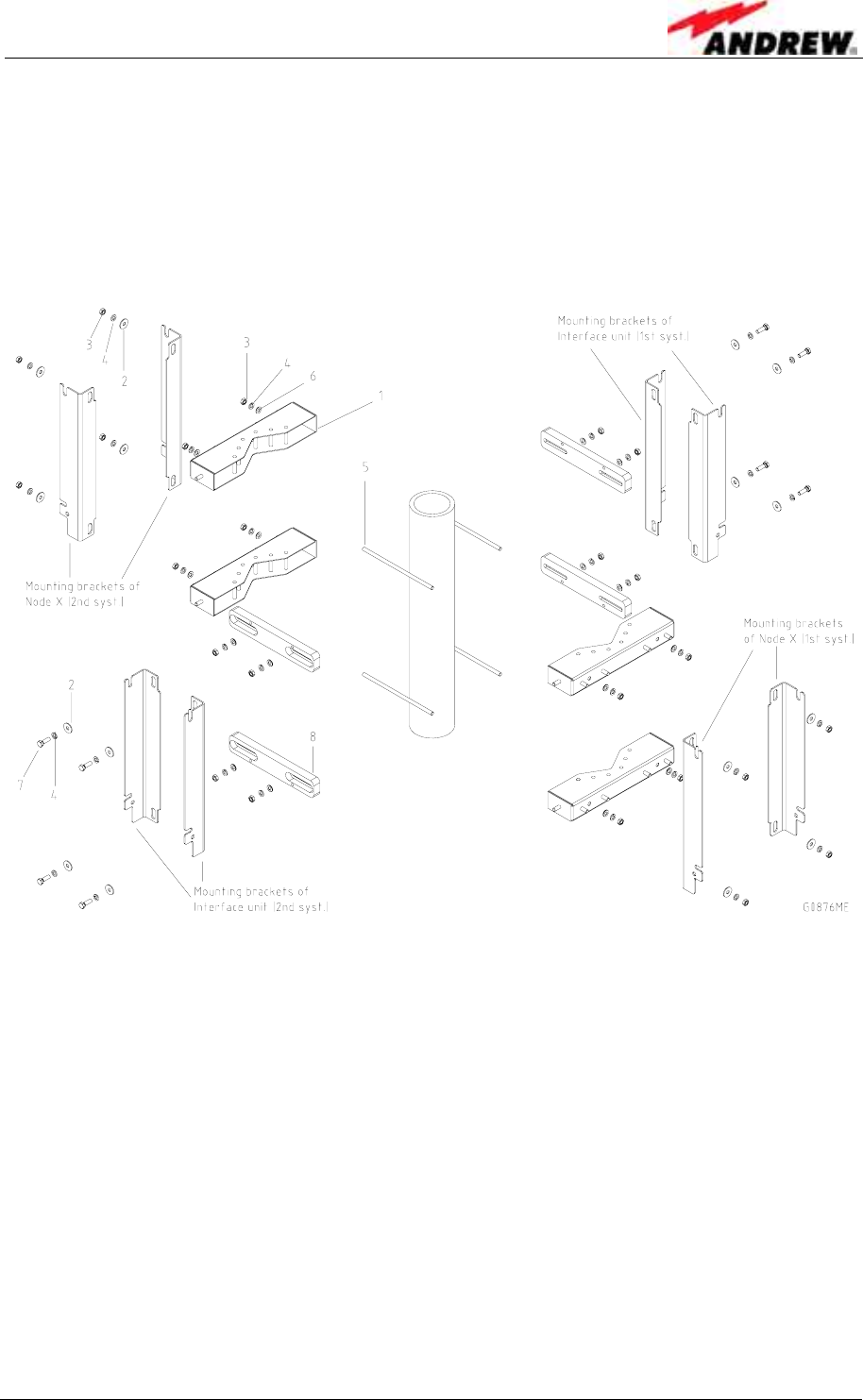
ID No: 161692 PRELIMINARY Page 19
• In case of two systems (figure 3-7) first mount the mounting brackets of the Node
C units; then adjust and mount the fasteners (no. 8) accordingly before fastening
the mounting brackets of the Interface Units to the fasteners.
• Hang the units into the respective mounting brackets and fasten the hexagon
head screws M10x20.
figure 3-7 Pole mounting two systems

User’s Manual for Node C Network Elements
Page 20 PRELIMINARY M0121A1A_uc.doc
3.2 ELECTRICAL INSTALLATION
3.2.1 General
Read the health and safety warnings in chapter 1.2 Health and Safety Warnings.
1. This unit contains dangerous voltages. Loss of life, severe personal
injury or property damage can be the result if the instructions contained
in this manual are not followed.
2. It is compulsory to ground the unit before connecting power supply. A
grounding bolt is provided on the cabinet to connect the ground bonding
cable.
3. Although the unit is internally protected against overvoltage, it is
strongly recommended to earth the antenna cables close to the unit’s
antenna connectors for protection against atmospheric discharge. In
areas with strong lightning it is strongly recommended to insert
additional lightning protection.
4. Hard wired installation of mains supply for the unit requires an easily
accessible separation device in the mains circuit.
5. Make sure that an appropriate circuit breaker and an overcurrent limiting
device are connected between mains and the unit.
6. A connection of mains supply to a power socket requires the power
socket to be nearby the unit.
7. The unit might be supplied from IT mains. (The maximum nominal line to
line voltage must not exceed 400VAC).
8. Incorrectly wired connections can destroy electrical and electronic
components.
9. To avoid corrosion at the connectors caused by electrochemical
processes, the material of the cable connectors must not cause a higher
potential difference than 0.6V (see electrochemical contact series).
10. It is sufficient to tighten the 7/16 or N antenna connector hand-screwed.
Any use of a tool (e.g. pair of pliers) might cause damage to the
connector and thus lead to malfunctioning of the unit.
11. For unstabilized electric networks which frequently generate spikes, it is
advised to use a voltage limiting device.
12. The unit complies with the surge requirement according to EN 61000-4-5
(fine protection), however, it is recommended to install an additional
medium (via local supply connection) and/or coarse protection (external
surge protection) depending on the individual application in order to
avoid damage caused by overcurrent.
13. Observe the labels on the front panels before connecting any cables.
3 Installation
ID No: 161692 PRELIMINARY Page 21
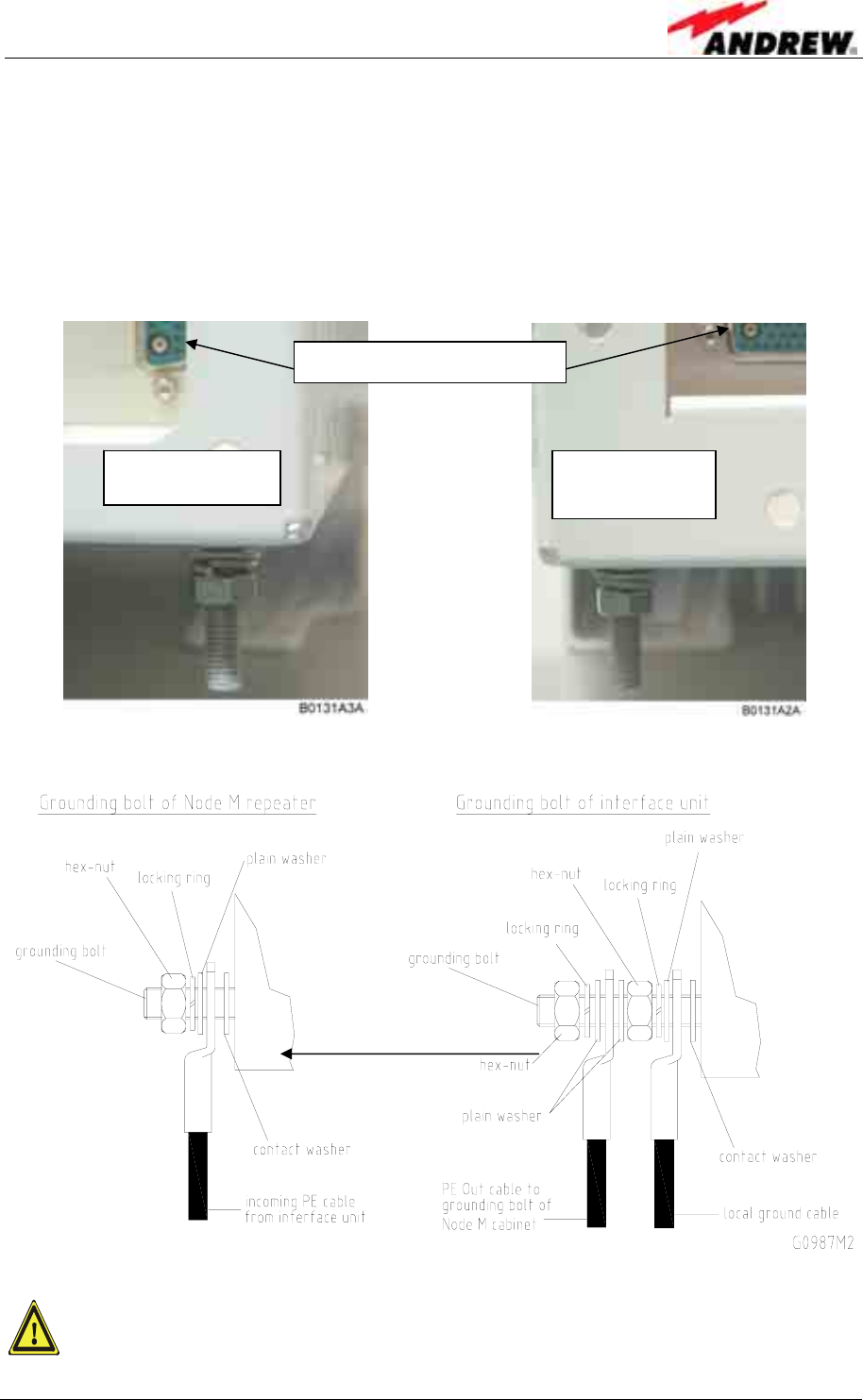
3.2.2 Grounding
Grounding the Node C and Interface Unit is mandatory. Connect an earth bonding
cable to the grounding connections provided at the cabinets of both the Node C and
Interface Unit according to the following illustrations.
Do not use the grounding connections to connect external devices.
figure 3-8 Grounding bolts
figure 3-9 Grounding a system
The PE cables must have a minimum cross section of 10mm2.
Node C cabinet Cabinet of
Interface Unit
Cable bridge connectors
User’s Manual for Node C Network Elements
Page 22 PRELIMINARY M0121A1A_uc.doc
3.2.3 Power Connection
Before connecting electrical power to the units, the system must be grounded as
described in the previous chapter.
Mains power must be connected at the mains connector of the Interface Unit. The
power supply plug is included with the Node C.
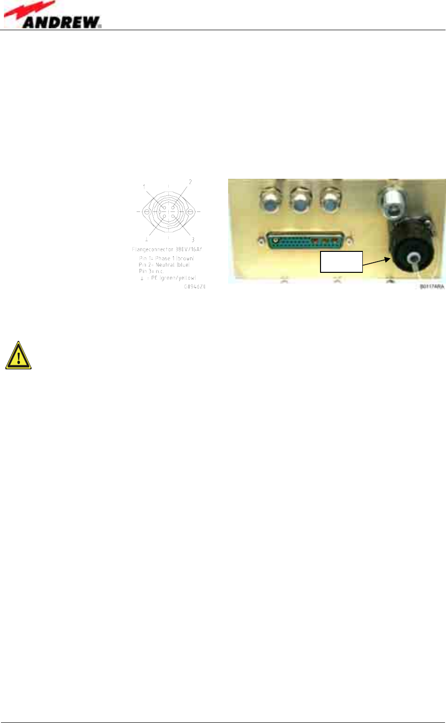
The correct wiring
of the power supply
plug is as follows:
figure 3-10 Power supply plug figure 3-11 Mains connector
A minimum cross section of 1.5 mm2 is required for the powersupply
connection. Each wire must observe the applicable national regulations
regarding loop impedance, voltage drop, and methods of installation.
Make sure to connect the correct voltage to the unit.
) Note: Do not connect or disconnect the power cord at the mains connector
while power is on. Turn off mains* power before connecting the
power cord at the Interface Unit, then, engage mains again.
* Mains power must be interrupted with an external AC breaker. For the AC breaker,
observe the following recommendation:
120 Volt / 20 Amp max. or 240 Volt / 16 Amp, single-phase, 50/60 Hz AC service is
needed, i.e. the external AC breaker should be 20 Amps max. for 120-Volt service or
16 Amps for 240-Volt service.
Mains
3 Installation
ID No: 161692 PRELIMINARY Page 23
3.2.4 Connection of the Antenna Cables
The Node C’s antenna connectors are 7/16 female (N female is an option). All
connectors are located at the bottom of the cabinet. An operator should refer to the
cable connectors manufacturer’s documentation for best mating procedures.
Furthermore, the bending radius of the antenna cables should be maintained at all
times.
There are several issues to be considered when selecting the cable and antenna
types.
• Smaller diameter cables are less expensive and easier to install but have
worse performance.
• Highly directional antennas with good front-back-ratios (40 dB is typical) are
recommended because they improve isolation and cell site selectivity.
Tighten the 7/16 (or N) connectors ONLY by hand. The use of pliers may
cause damage to the connector and impair the performance of the Node C.
figure 3-12 Front view of antenna connections
3.2.5 Connection of Cable Bridge
The Interface Unit and the Node C are connected via a cable bridge. The bridge
ports 12V, 28V, ground, USB, and RS232 between the two units as well as the
general alarming and signalling. It is also the interconnection and intercommunication
bus between the units.
Coverage antenna (to mobile) Donor antenna (to base station)
Primary Diversity
User’s Manual for Node C Network Elements
Page 24 PRELIMINARY M0121A1A_uc.doc
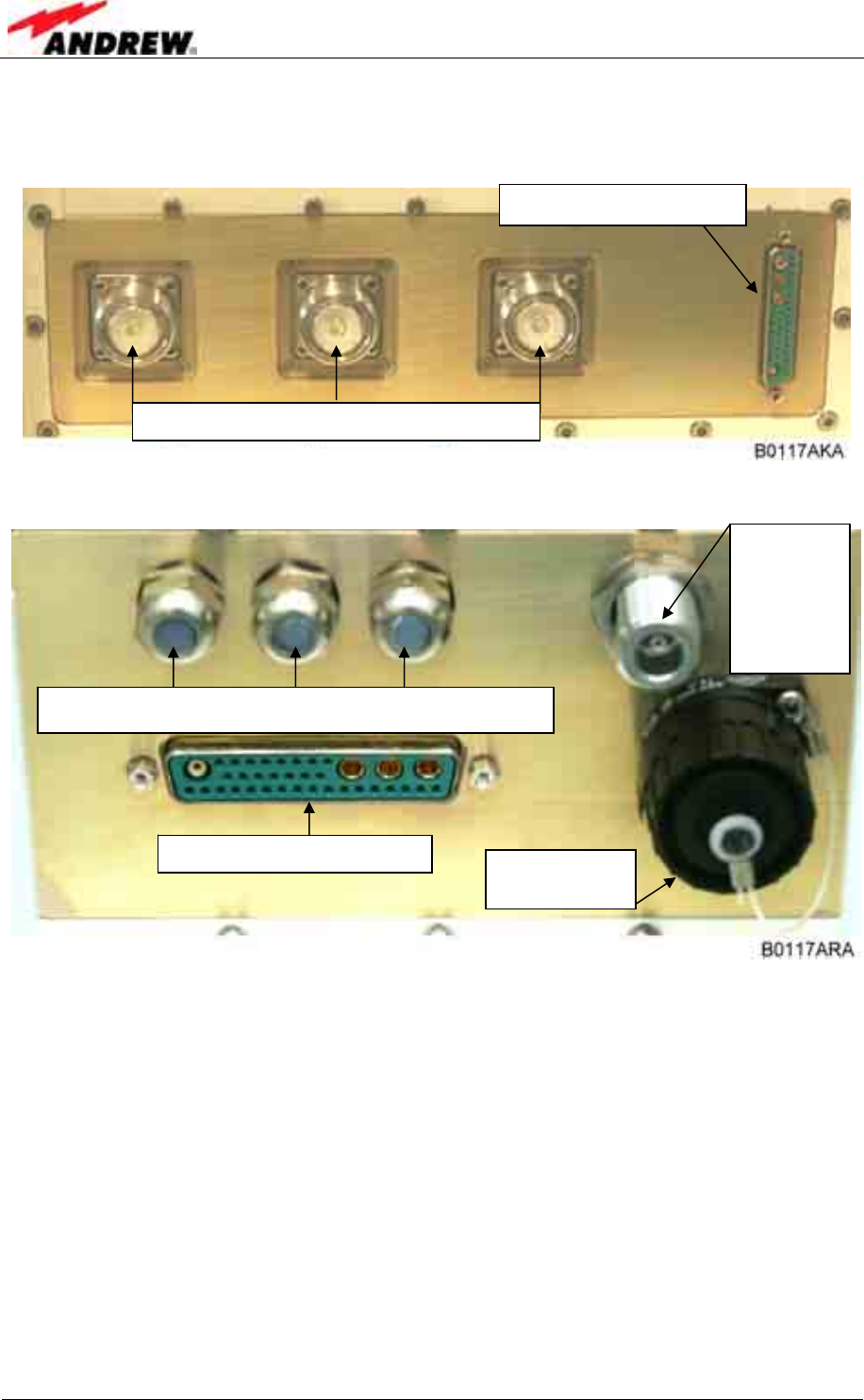
The cable bridge connectors are located at the bottom of the Node C and Interface
Unit.
figure 3-13 Connector panel of the Node C
figure 3-14 Connector panel of the Interface Unit
3.2.6 Connections for Optional Equipment
The Interface Unit connector panel has ports for external equipment, such as a
modem operating in a different network and external alarms. These connectors may
be used entirely at the operator’s discretion.
Cable bridge connector
Antenna connnectors
Antenna
connector
for modem
(operating
in different
network)
Cable glands for external alarms, summary alarm & PSTN
Cable bridge connector Mains power
connectors
4 Commissioning
ID No: 161692 PRELIMINARY Page 25
4 COMMISSIONING
4.1 GENERAL
Read the health and safety warnings in chapter 1.2 Health and Safety Warnings and
observe the following step-by-step procedure.
• Do not operate the Node C without terminating the antenna connectors. The
antenna connectors may be terminated by connecting them to their respective
antennas or to a dummy load.
• Only qualified personnel should carry out the electrical, mechanical,
commissioning, and maintenance activities that require the unit to be powered
on when open.
• When opening the Node C or interface box do not damage the warranty labels
on the internal devices. The warranty is void if the seals are broken.
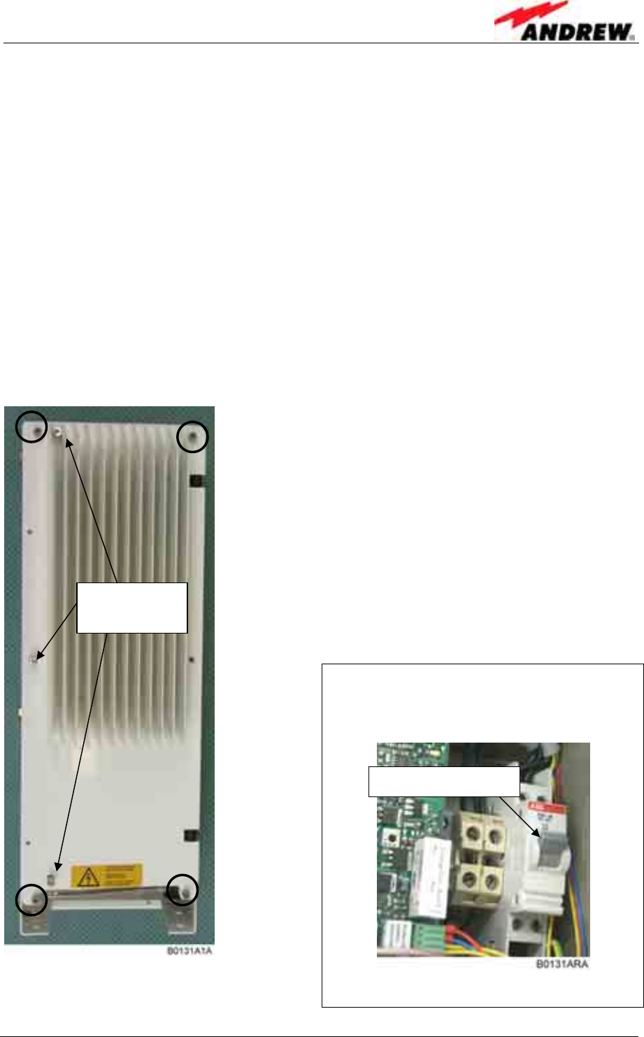
To open the cabinet of the Interface Unit, first remove
the front cover plate by loosening the four M5 socket
head cap screws (circle-marked in figure to the left).
Do not remove those screws. When they are
loosened the front cover plate can be taken off.
To open the housing, unscrew the three M5 socket
head cap screws (captive) of the top cover of the
Interface Unit.
) Note: Do not forget to reinstall the front
cover afterwards to ensure safe
operation.
) Note: Before closing the Interface
Unit, make sure that the mains power
switch inside is set to On:
figure 4-1 Front and top cover screws figure 4-2 Position of mains power switch
Three top
cover screws
Mains power switch

User’s Manual for Node C Network Elements
Page 26 PRELIMINARY M0121A1A_uc.doc
4.2 SOFTWARE SETUP
4.2.1 Remote Control
For remote control and/or supervision of the Node C the following services are
provided:
• An OMC-type software platform (see separate manual)
• SMS alarm-forwarding (for details see chapter 5.2.5 Alarmforwarding)
• Web page (see chapter 4.2.4 and online-help)
4.2.2 Connection Devices
To connect to the Node C, the following devices are available:
• Locally, via the RS232 interface of the distribution & alarm board of the Interface
Unit (see figure 5-15) using either the connected USB cable or the null modem
cable which is part of the delivery for the connection of a PC or laptop.
• Remotely, if the optional modem is installed in the Interface Unit. All local
commands may be issued via the web interface over the remote modem.
4.2.3 Connection Procedures
4.2.3.1 Setup Overview
Four steps are required to set up a connection to the Node C.
1. Install the USB to serial adapter in the computer. The USB adapter is part of
the delivery and is already connected to the RS232 connector of the
distribution & alarm board (see figure 4-3). For the first connection, install the
correct driver from the CD (see chapter 4.2.3.2 Installing the USB driver). For
the connection via null modem cable, disconnect the USB connector from the
RS232 connector (see figure 4-3) and connect the null modem cable.
2. Configure the connection device, i.e. RS232/USB/modem. (See section a) of
chapter 4.2.3.3, 4.2.3.4, or 4.2.3.5 depending on the operating system.)
3. Setup a connection:
a) Direct connection via PC or laptop: similar to connecting a computer to a
standard Internet service provider (ISP); see section b) of chapter 4.2.3.3
or 4.2.3.5 depending on the operating system.
b) Modem connection; see section b) of chapter 4.2.3.4.
4. Establish the connection; see section c) of chapter 4.2.3.3, 4.2.3.4, or 4.2.3.5
depending on the operating system.
The following instructions are for Windows XP and Windows 2000. This procedure
must be done only once with the first setup.
4 Commissioning
ID No: 161692 PRELIMINARY Page 27
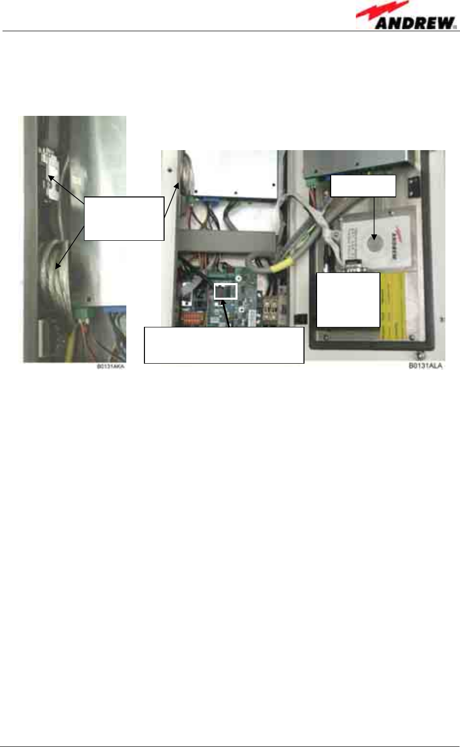
4.2.3.2 Installing the USB driver
The USB adapter and the driver CD are located inside the Interface Unit:
figure 4-3 USB and null modem cable connection
When the USB adapter is connected to a PC for the first time, the USB driver must
be installed. The Node C and Interface Unit must be switched on for the procedure.
To install the driver, proceed as follows:
• Connect the USB cable of the USB adapter to the USB port of the PC.
• Then, wait until the system (valid from Windows98ME) delivers the message that
a new USB device was found and asks for the driver.
• Put the CD into the CD-ROM drive of the PC and the system will ask how to
search for the driver.
• Select the automatic search (usually default), confirm, and wait while the system
searches for the driver.
• The successful installation will be informed by a message that the new hardware
was successfully installed.
• After confirming this message the CD can be taken out of the drive and put back
into the plastic cover inside the Interface Unit.
• Reboot the PC.
When the connection is made the next time, this procedure is no longer necessary.
USB adapter
with USB
cable
Driver CD
RS232 connector for USB or
null modem cable connection
Position of
optional
modem
User’s Manual for Node C Network Elements
Page 28 PRELIMINARY M0121A1A_uc.doc
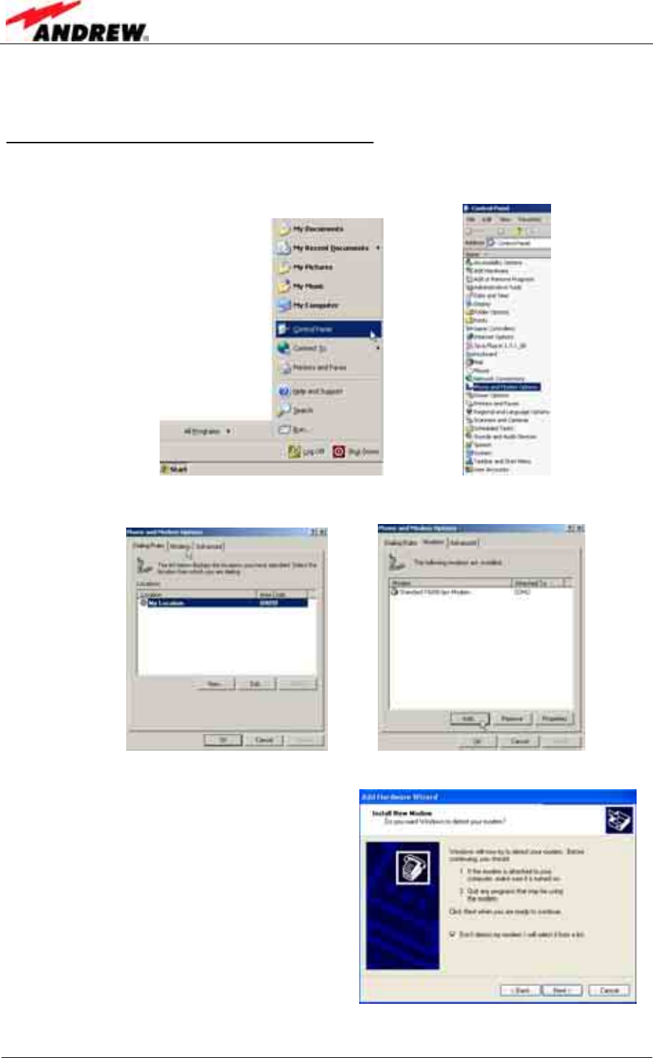
4.2.3.3 Direct connection for Windows XP
a) Setting up the device for the direct connection
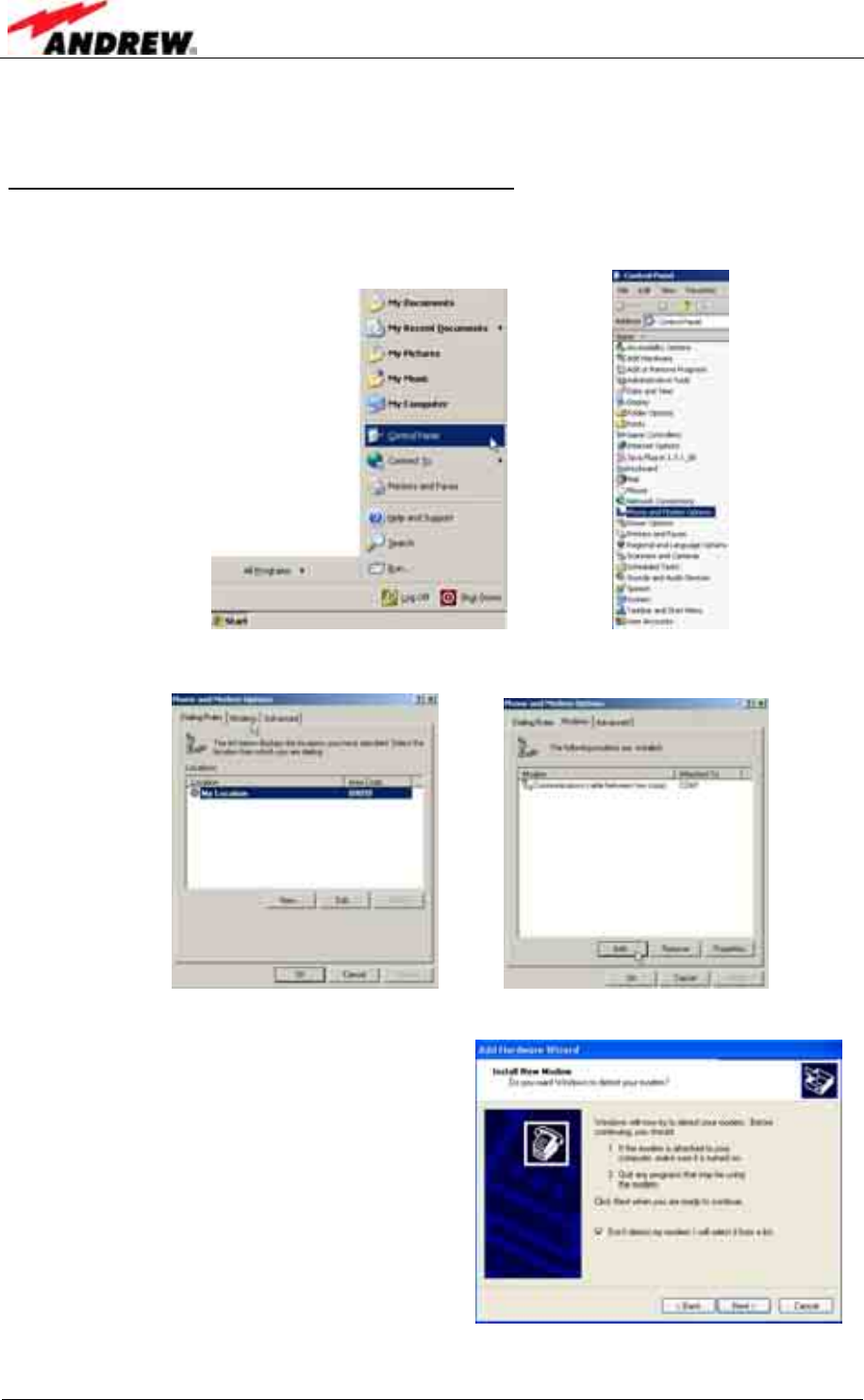
1. To start the Phone and Modem Options, choose Start→Control Panel→Phone
and Modem Options.
2. Select the Modems tab and click the Add... button.
3. Choose to select from a list.
Click Next.
4 Commissioning
ID No: 161692 PRELIMINARY Page 29
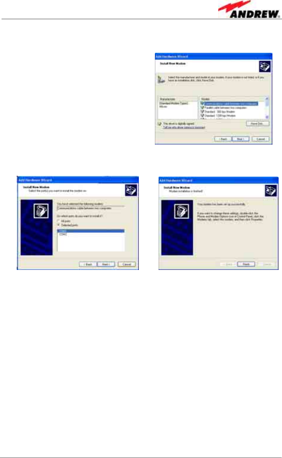
4. For a direct connection choose the Communication cable between two
computers as device.
Click Next.
5. Select your port (usually COM1 for a direct connection), continue with Next,
and in the next window click Finish.
User’s Manual for Node C Network Elements
Page 30 PRELIMINARY M0121A1A_uc.doc
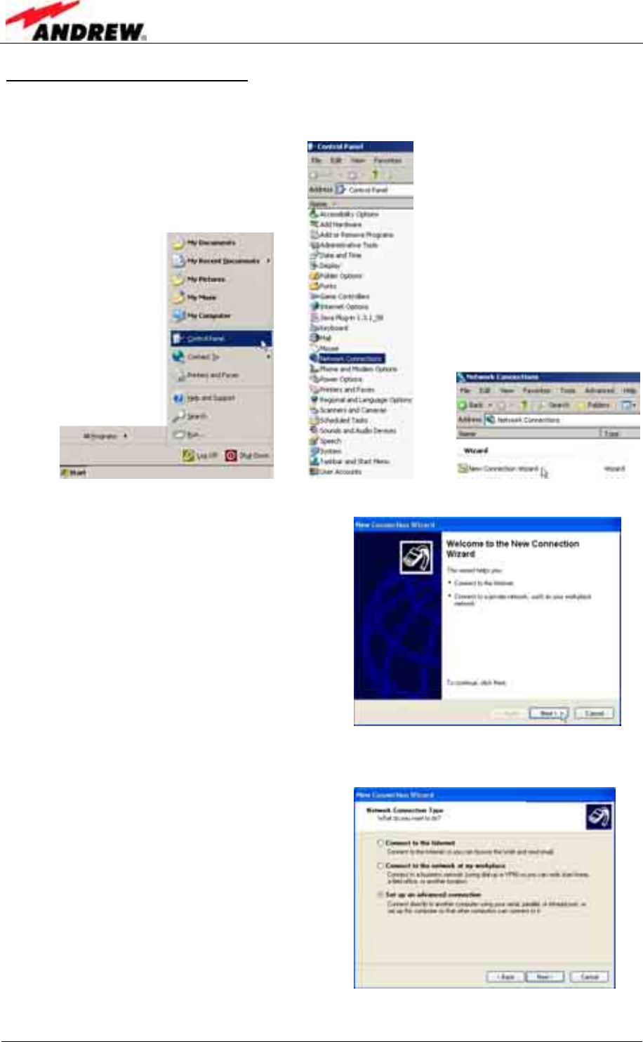
b) Setting up a direct connection
1. Choose Start→Control Panel→Network Connections→New Connection
Wizard.
2. The first page is the Welcome window:
Continue with Next.
3. In the Network Connection Type window, select Set up an advanced
connection.
Click Next.
4 Commissioning
ID No: 161692 PRELIMINARY Page 31
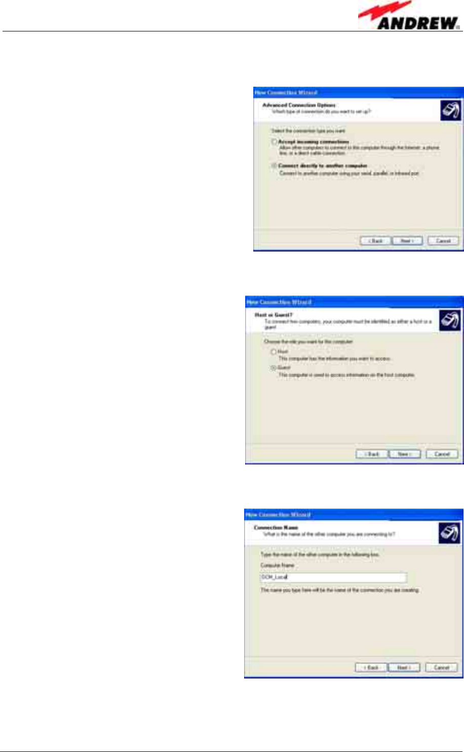
4. In the Advanced Connection Options, choose Connect directly to another
computer.
Click Next.
5. In the next window choose Guest.
Click Next.
6. Next, enter a name for the new connection.
User’s Manual for Node C Network Elements
Page 32 PRELIMINARY M0121A1A_uc.doc
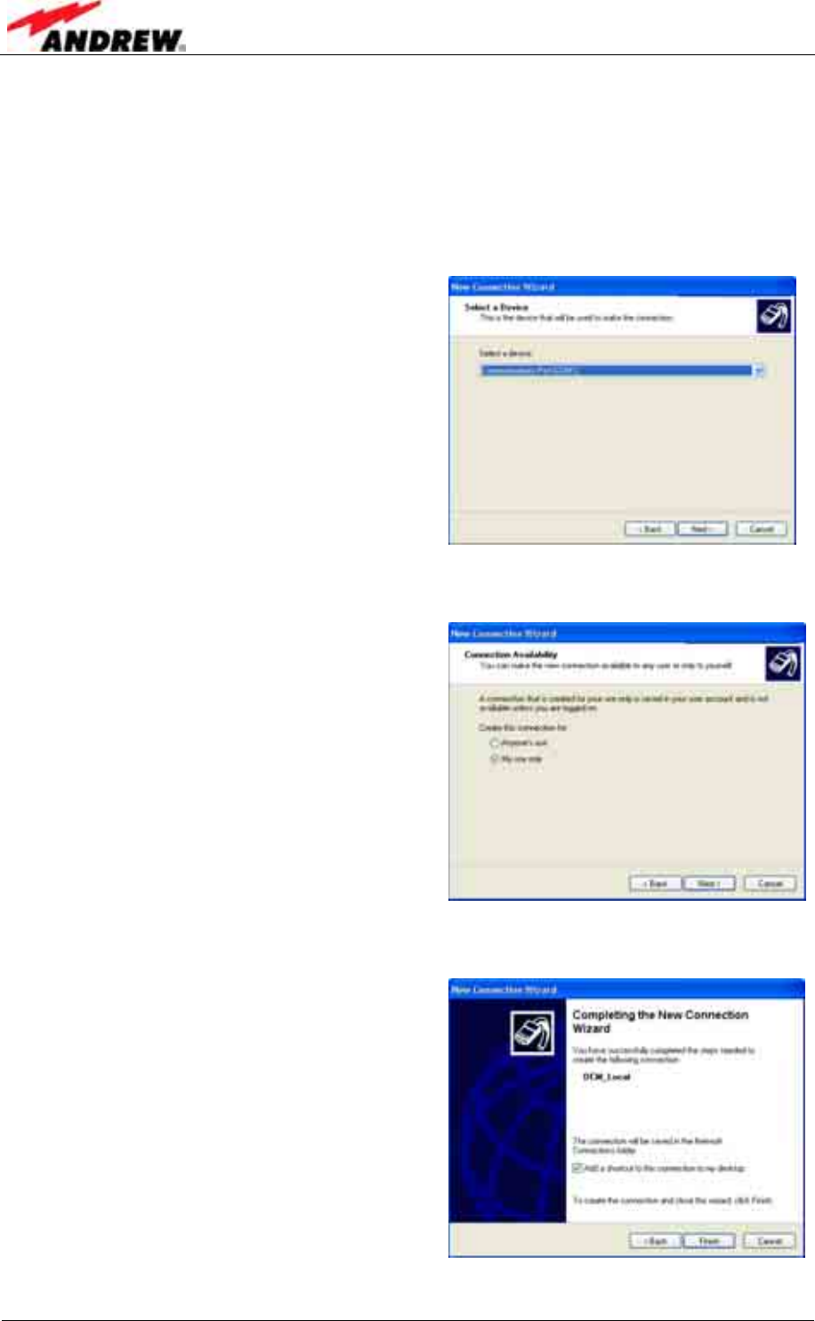
7. The next window is Select a Device.
This window will provide a drop-down list of known communication ports
(devices) to choose from. Choose a serial port. If the RS232 is used, this port
is most likely (COM1). If a USB port is used some other COM port number
should be used. In such a case, take care that the USB driver is installed and
connected before completing this selection or the connection will not work.
Click Next.
8. The next window is Connection Availability. Choose My use only.
Click Next.
9. In the window Completing the New Connection Wizard, choose whether to
add a shortcut to the desktop.
Click Finish
4 Commissioning
ID No: 161692 PRELIMINARY Page 33
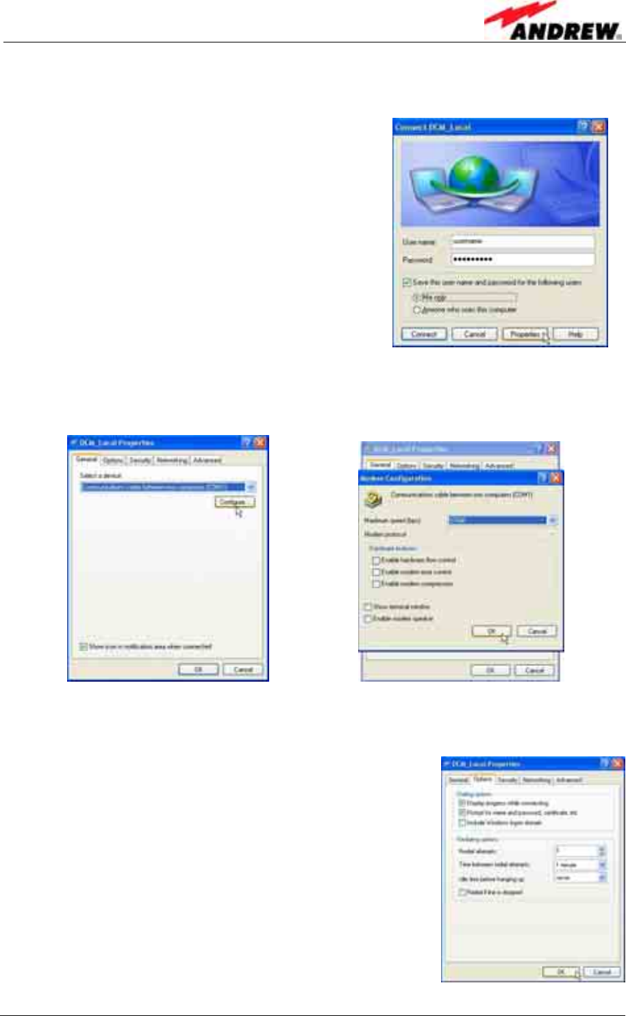
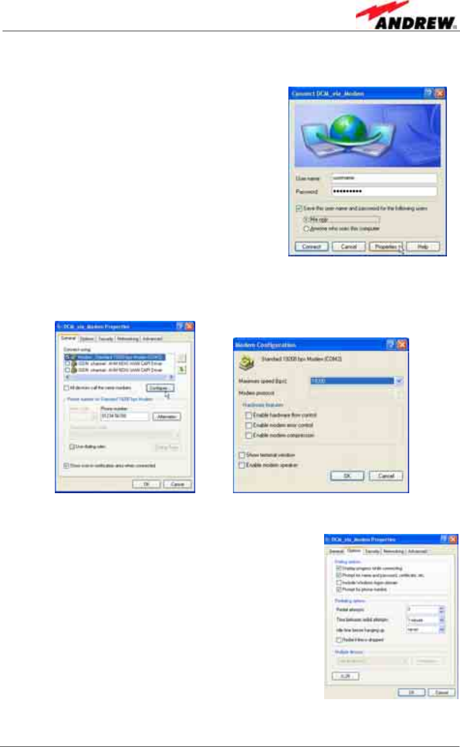
In the Connection window, enter User name and Password. Select to Save
user name and password ... for Me only.
Click Properties.
10. Under the General tab ensure the correct device is selected. Click Configure,
and in the Modem Configuration window, choose 57600 for Maximum speed.
No other box should be checked. Click OK.
11. Select the Options tab and make sure that all dialling options except the last
one (Include Windows logon domain) are checked.
Set the redialling options as required and click OK.
Enter:
User name: <username>
Password: <password>
User’s Manual for Node C Network Elements
Page 34 PRELIMINARY M0121A1A_uc.doc
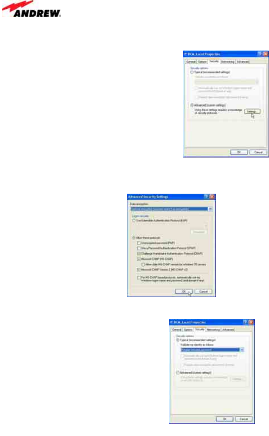
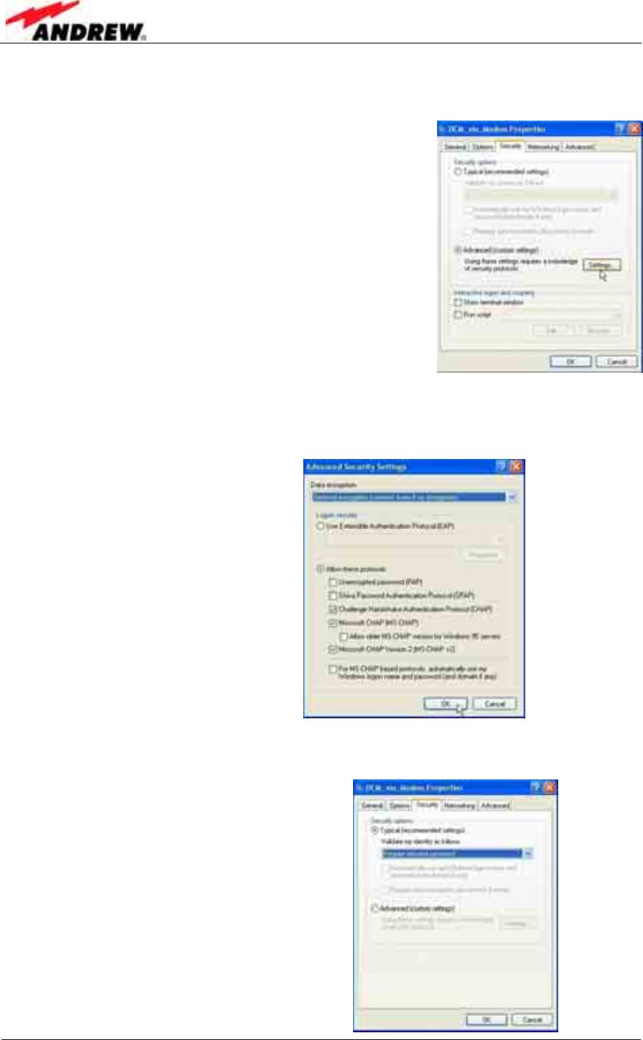
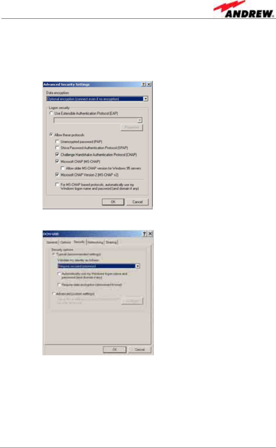
12. Select the Security tab, select Advanced (custom settings), and click
Settings.
13. Only allow Challenge Handshake Authentication Protocol (CHAP)
Microsoft CHAP (MS-CHAP) and
Microsoft CHAP Version 2 (MS-CHAP v2) protocols.
Click OK.
14. Click Typical and choose Require secured password.
Click OK.
4 Commissioning
ID No: 161692 PRELIMINARY Page 35
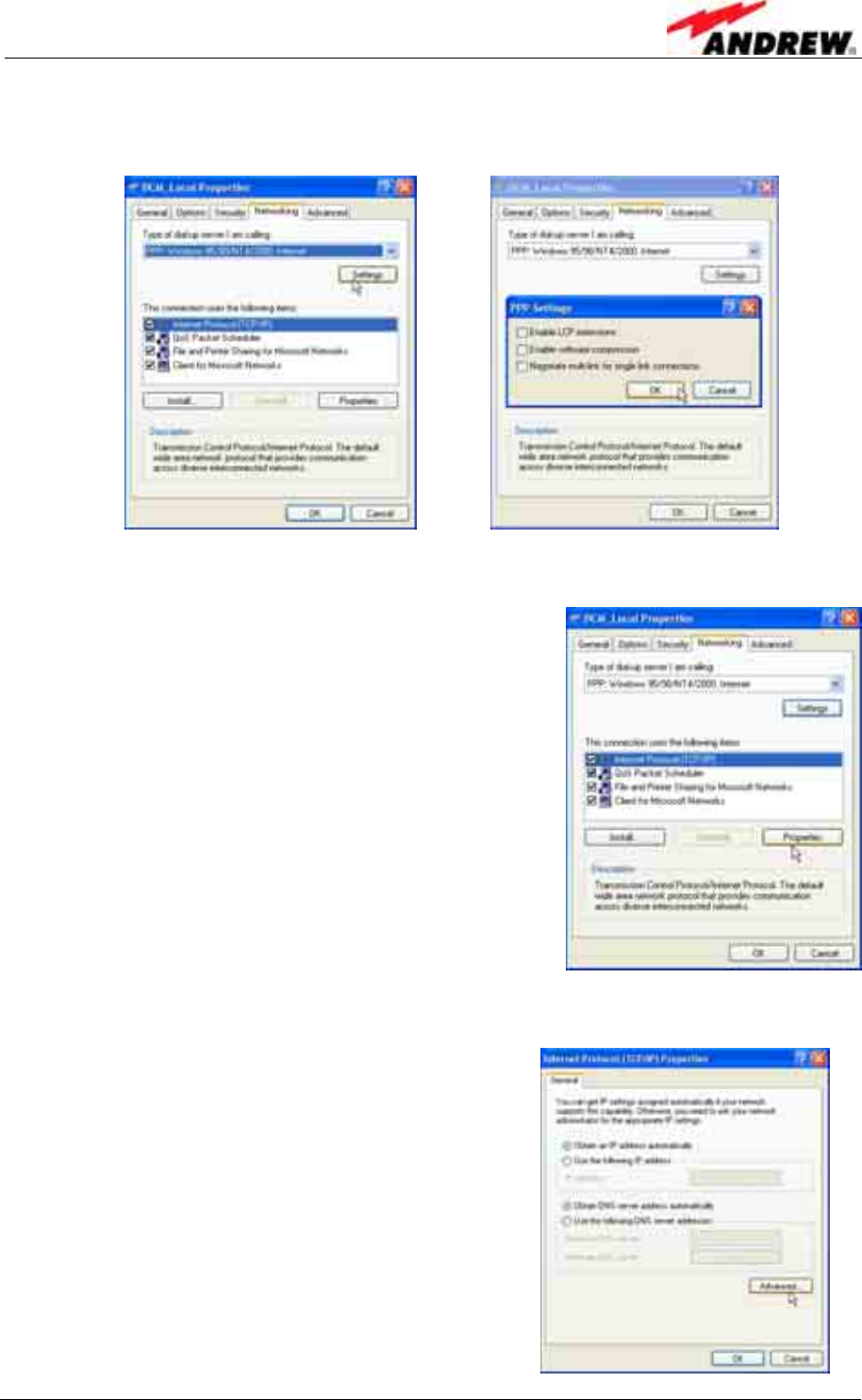
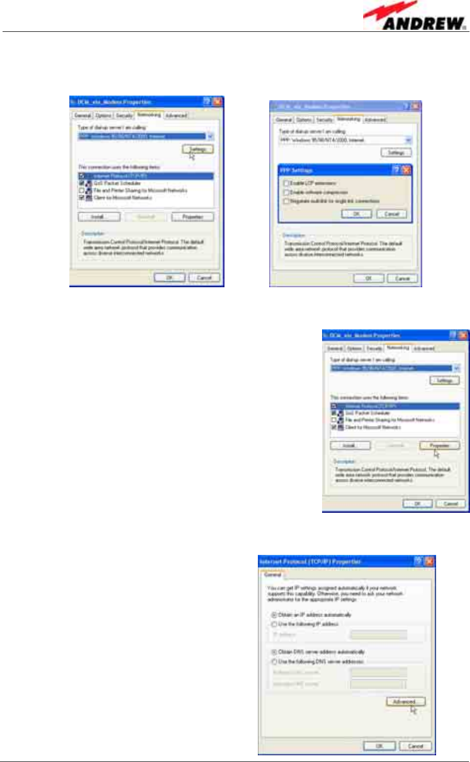
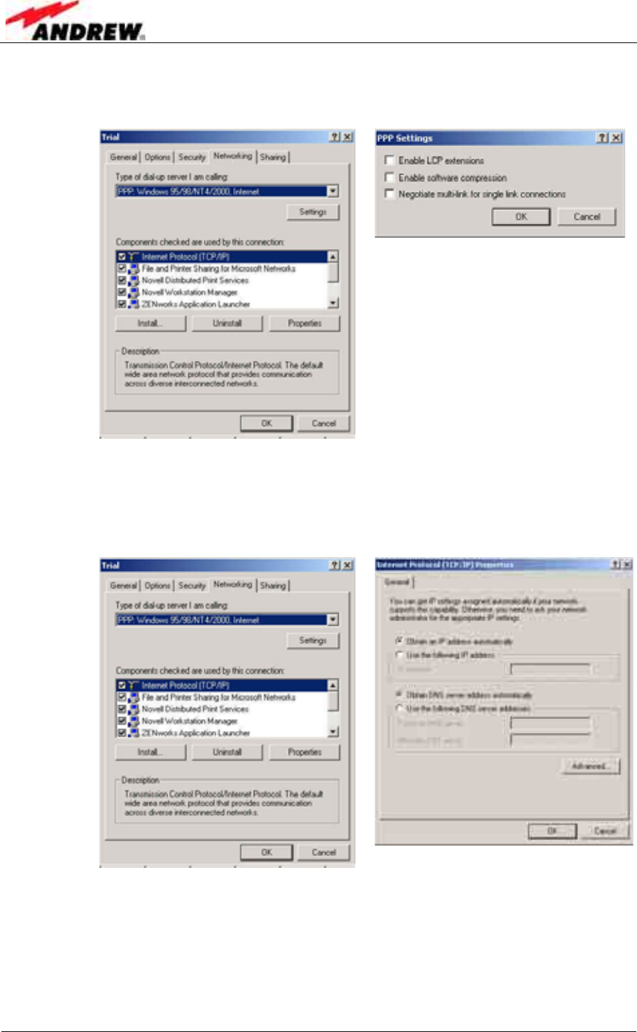
15. Select the Networking tab and click the Settings button. There are 3 PPP
settings. Make sure they are all OFF and click OK.
16. In the Networking window, highlight the Internet Protocol (TCP/IP)
component and click the Properties tab.
17. Obtain an IP address automatically and Obtain DNS server address
automatically must be checked.
Click Advanced.
User’s Manual for Node C Network Elements
Page 36 PRELIMINARY M0121A1A_uc.doc
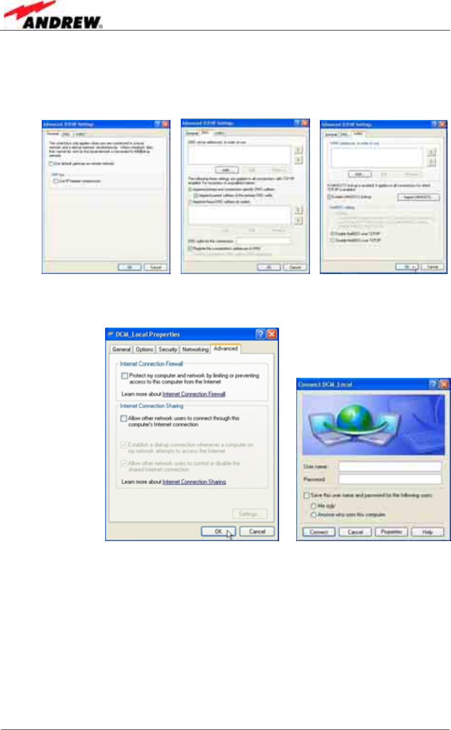
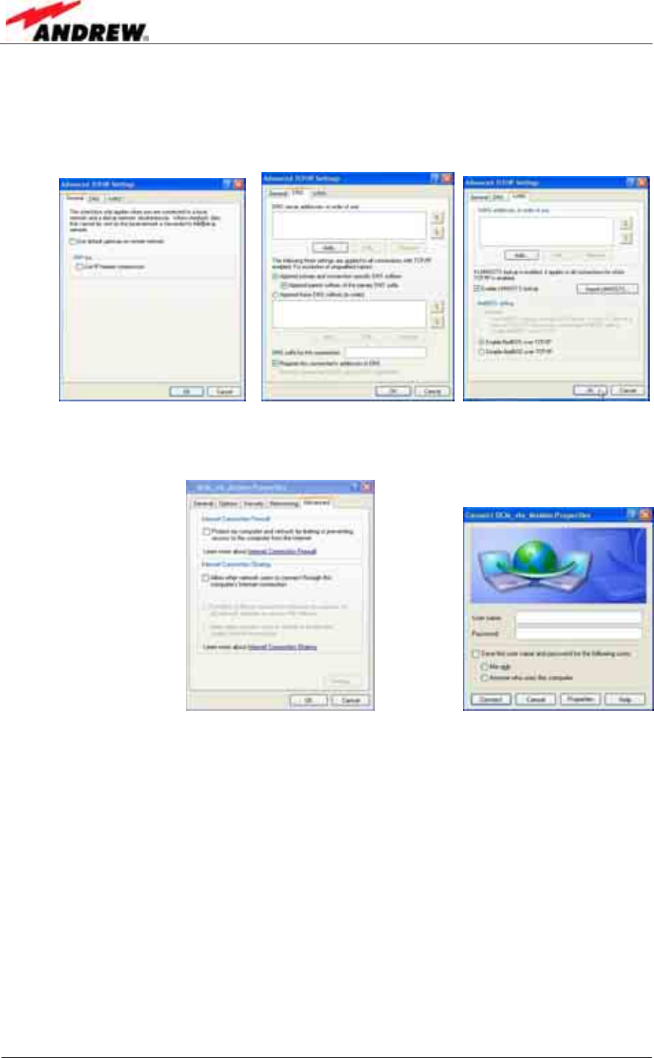
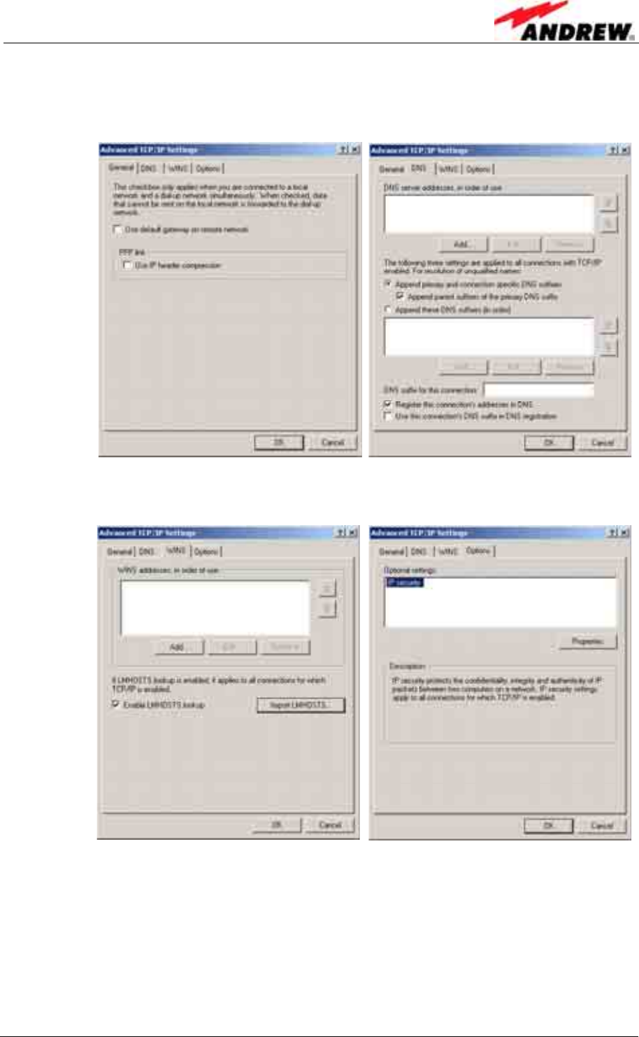
18. In the General tab, uncheck all boxes.
In the DNS tab, make sure Append primary and Append parent and
Register this connection are checked.
In the WINS tab, make sure Enable LMHOSTS lookup is checked. Click OK.
19. For Internet Connection Firewall and Internet Connection Sharing
settings, select the Advanced tab. Click OK to get back to the Connect
window.
20. The connection procedure is described in the following. If the connection is to
be made directly from the Connect window, step one of the following
description can be skipped.
4 Commissioning
ID No: 161692 PRELIMINARY Page 37
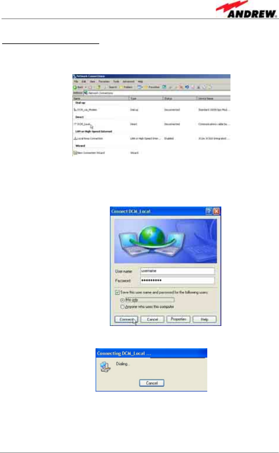
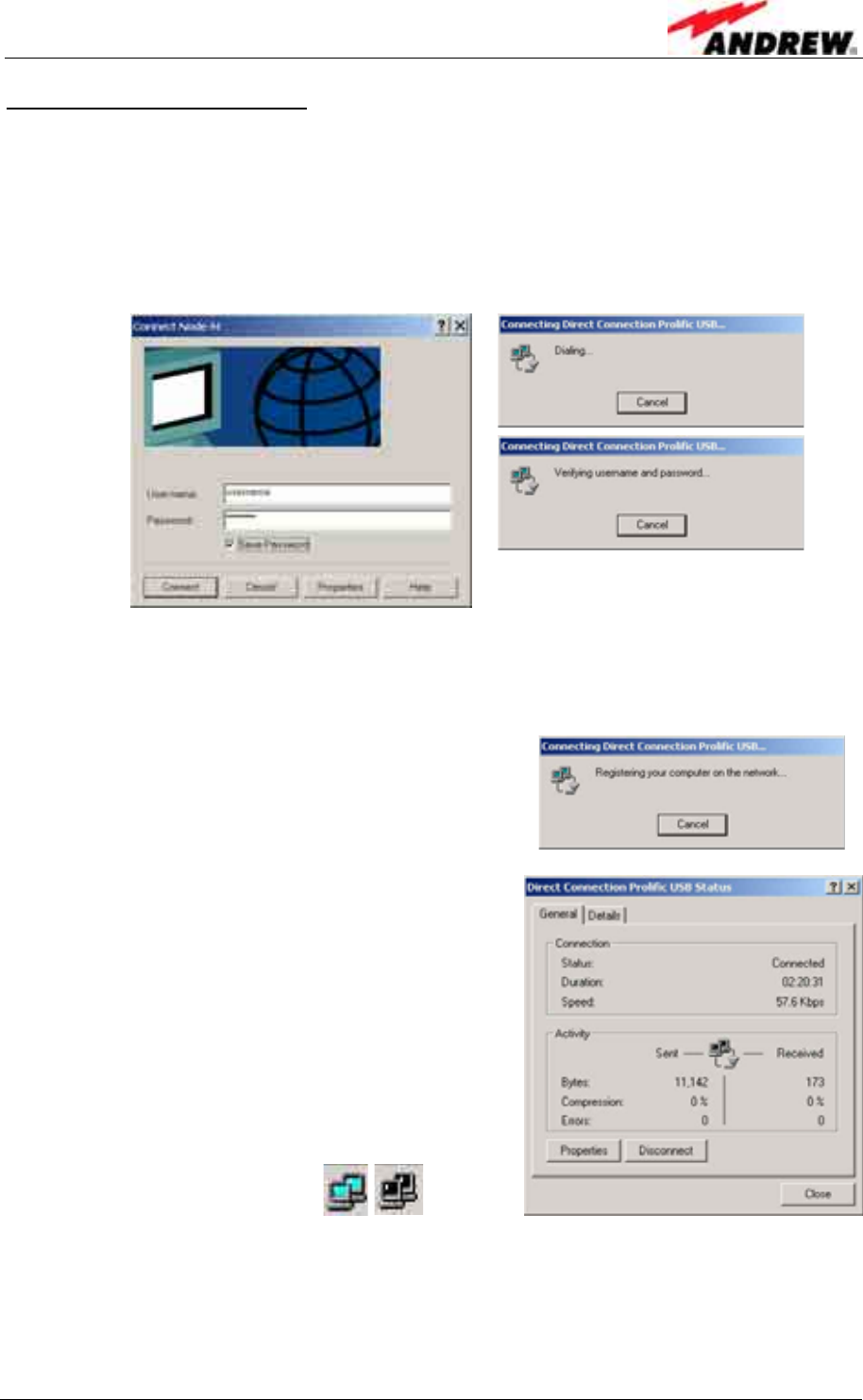
c) Establishing the connection
1. Choose Start→Control Panel→Network Connections→<connection
name> (i.e. in this example “DCM_Local”).
The properties of this connection should already have been setup.
2. Enter <username> in the User name field.
Enter <password> in the Password field.
Select to Save this user name and password ... for Me only.
Click Connect.
While the connection is established the following window is displayed
When the connection is successful an icon will appear in the system tray. This icon
will “light up” to indicate network activity between the computer and the Node C. To
check the status of the connection, click on the icon.
Please continue with chapter 4.2.3.6 Accessing the web page .
User’s Manual for Node C Network Elements
Page 38 PRELIMINARY M0121A1A_uc.doc
4.2.3.4 Modem connection for Windows XP
a) Setting up the device for the modem connection
1. To start the Phone and Modem Options, choose Start→Control Panel→Phone
and Modem Options.
6. Select the Modems tab and click the Add... button.
7. Choose to select from a list.
Click Next.
4 Commissioning
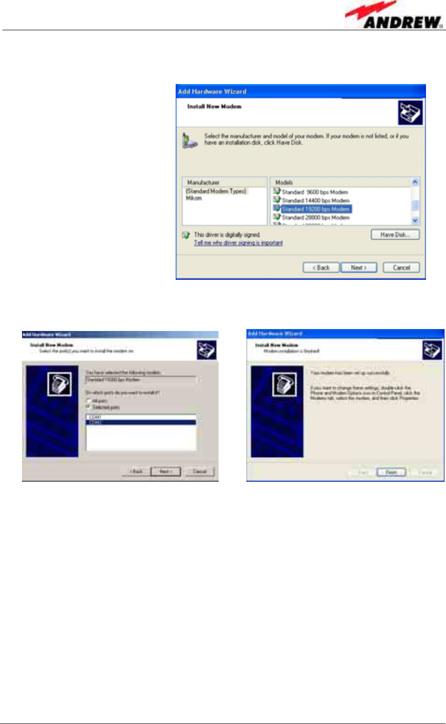
ID No: 161692 PRELIMINARY Page 39
8. For a modem connection, choose the Standard 19200 bps Modem as
device.
Click Next.
9. Select your port (usually COM2 for a modem connection), continue with Next,
and in the next window click Finish.
User’s Manual for Node C Network Elements
Page 40 PRELIMINARY M0121A1A_uc.doc
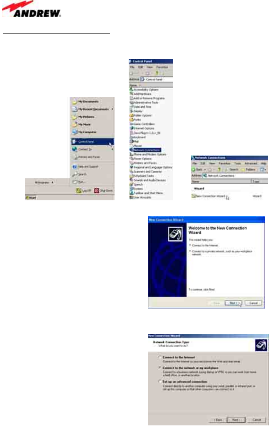
b) Setting up a modem connection
10. To start, choose Start→Control Panel→Network Connections→New
Connection Wizard.
11. The first window is the Welcome window:
Continue with Next.
12. In the Network Connection Type window, select Connect to the network at
my workplace.
Click Next.
4 Commissioning
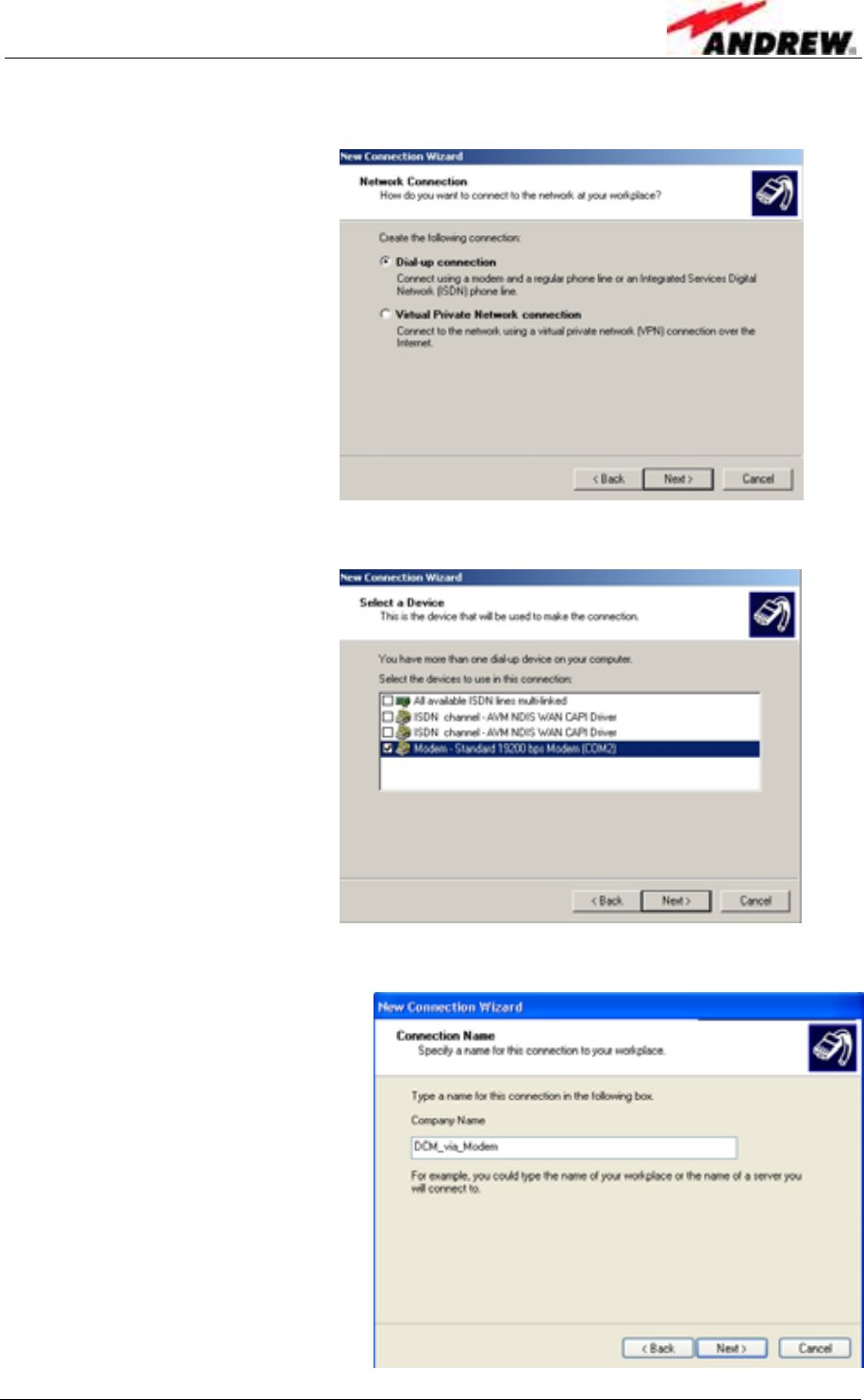
ID No: 161692 PRELIMINARY Page 41
13. In the Network Connection window, choose Dial-up connection.
Click Next.
14. Select the Standard 19200 bps Modem as device.
Click Next.
15. Next, enter a name for the new connection.
User’s Manual for Node C Network Elements
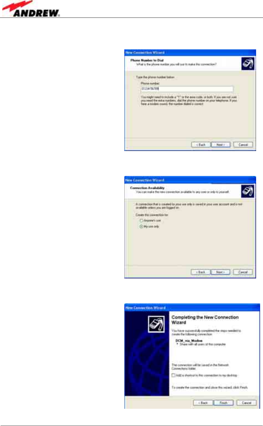
Page 42 PRELIMINARY M0121A1A_uc.doc
16. In the next window enter the phone number of the modem that is installed in
the Node C.
Click Next.
17. The next window is Connection Availability. Choose My use only.
Click Next.
18. In the window Completing the New Connection Wizard, choose whether to
add a shortcut to the desktop.
Click Finish
4 Commissioning
ID No: 161692 PRELIMINARY Page 43
19. In the Connection window, enter username and password. Select to Save
user name and password ... for Me only.
Click Properties.
20. Under the General tab ensure the correct device is selected. Click Configure,
and in the Modem Configuration window, choose 19200 for Maximum speed.
No other box should be checked. Click OK.
21. Select the Options tab and make sure that all dialling options except Include
Windows logon domain are checked.
Set the redialling options as required and click OK.
Enter:
User name: <username>
Password: <password>
User’s Manual for Node C Network Elements
Page 44 PRELIMINARY M0121A1A_uc.doc
22. Select the Security tab, select Advanced (custom settings), and click
Settings.
23. Only allow Challenge Handshake Authentication Protocol (CHAP)
Microsoft CHAP (MS-CHAP) and
Microsoft CHAP Version 2 (MS-CHAP v2) protocols.
Click OK.
24. Click Typical and choose
Require secured password.
Click OK.
4 Commissioning
ID No: 161692 PRELIMINARY Page 45
25. Select the Networking tab and click the Settings button. There are 3 PPP
settings. Make sure they are all OFF and click OK.
26. In the Networking window, highlight the Internet Protocol (TCP/IP)
component and click the Properties tab.
27. Obtain an IP address automatically and Obtain DNS server address
automatically must be checked.
Click Advanced.
User’s Manual for Node C Network Elements
Page 46 PRELIMINARY M0121A1A_uc.doc
28. In the General tab, uncheck all boxes.
In the DNS tab, make sure Append primary and Append parent and
Register this connection are checked.
In the WINS tab, make sure Enable LMHOSTS lookup is checked. Click OK.
29. For Internet Connection Firewall and Internet Connection Sharing
settings, select the Advanced tab. Click OK to get back to the Connect
window.
30. The connection procedure is described in the following. If the connection is to
be made directly from the Connect window, step one of the following
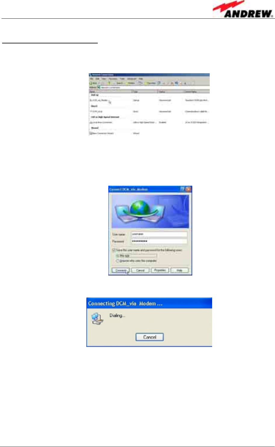
description can be skipped.
4 Commissioning
ID No: 161692 PRELIMINARY Page 47
c) Establishing the connection
1. Choose Start→Control Panel→Network Connections→<connection
name> (i.e. in this example “DCM_via_Modem”).
The properties of this connection should already have been setup.
2. Enter the term “username” in the User name field and the term “password” in
the Password field as shown below.
Select to Save this user name and password ... for Me only.
Click Connect.
While the connection is established the following window is displayed:
When the connection is successful an icon will appear in the system tray. This icon
will “light up” to indicate network activity between the computer and the Node C. To
check the status of the connection, click on the icon.
Please continue with chapter 4.2.3.6 Accessing the web page.
User’s Manual for Node C Network Elements
Page 48 PRELIMINARY M0121A1A_uc.doc
4.2.3.5 Direct connection for Windows 2000
a) Setting up the device for the direct connection
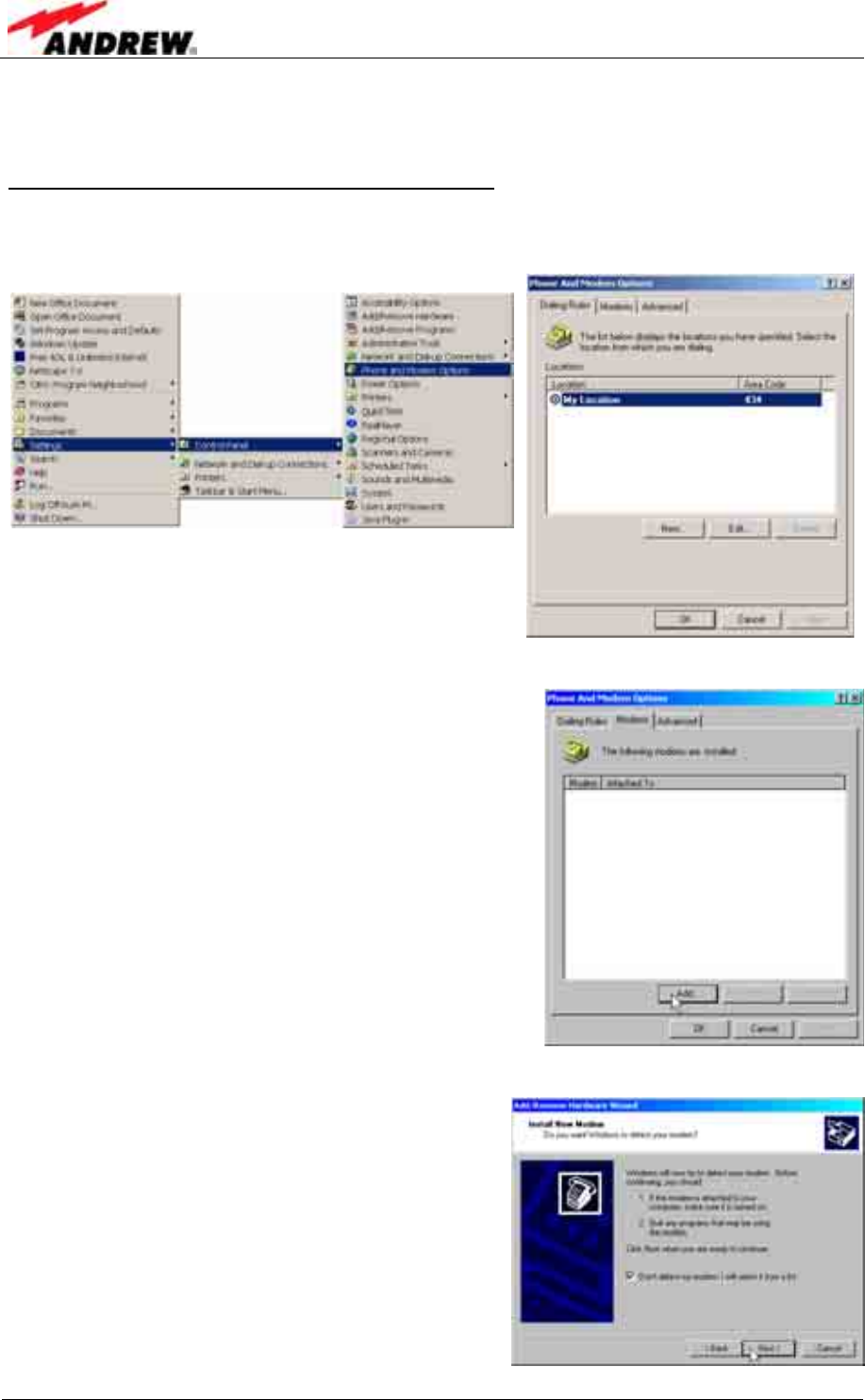
1. To start the Phone and Modem Options, click
Start→Settings→Control Panel→Phone and Modem Options.
2. Click the Modems tab and choose Add... .
3. Choose to select from a list, click Next.
4 Commissioning
ID No: 161692 PRELIMINARY Page 49
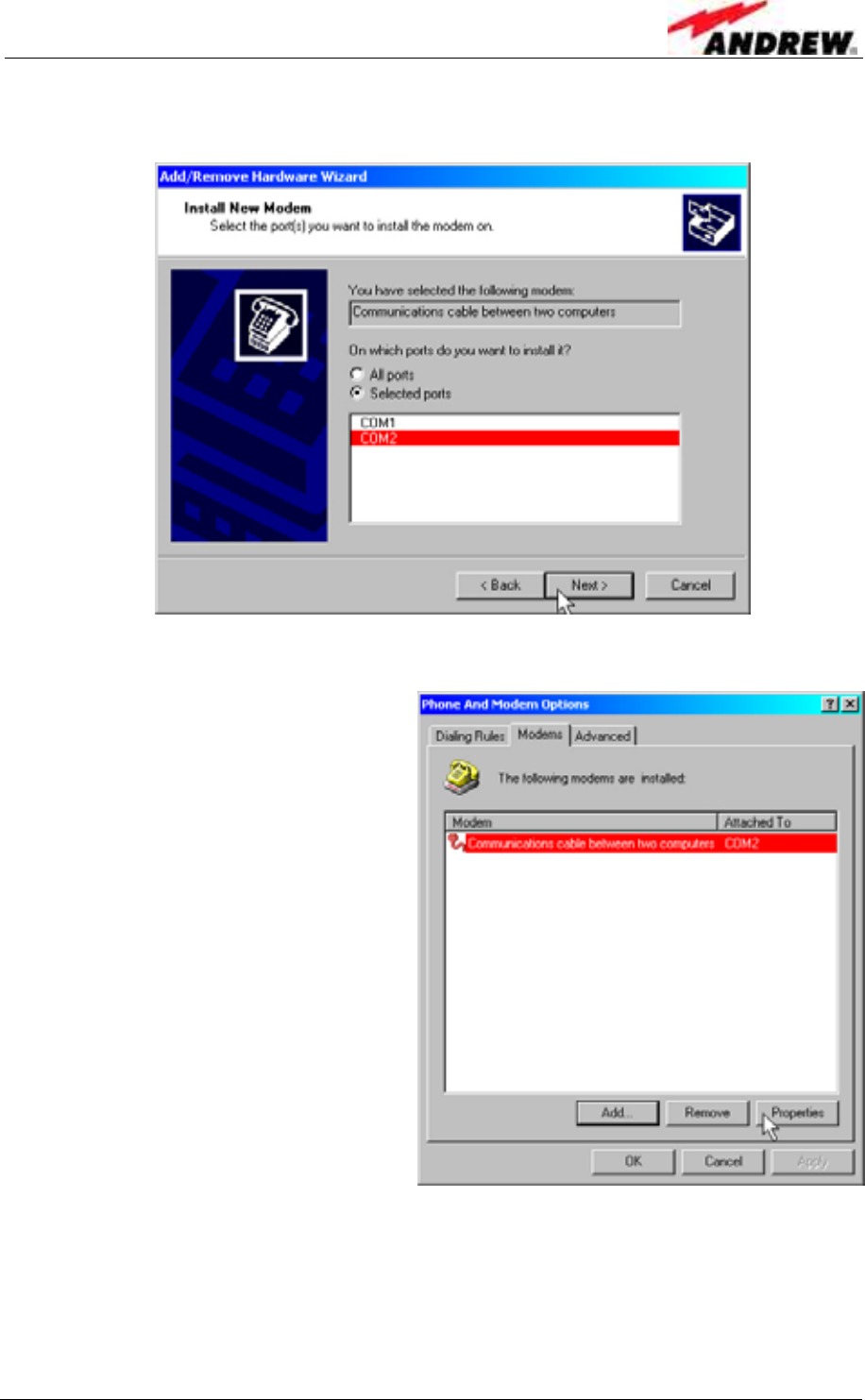
4. Select your port, continue with Next, and in the next window click Finish.
5. Highlight the port associated with the direct connection of the RS232 or USB
port. Click Properties.
User’s Manual for Node C Network Elements
Page 50 PRELIMINARY M0121A1A_uc.doc
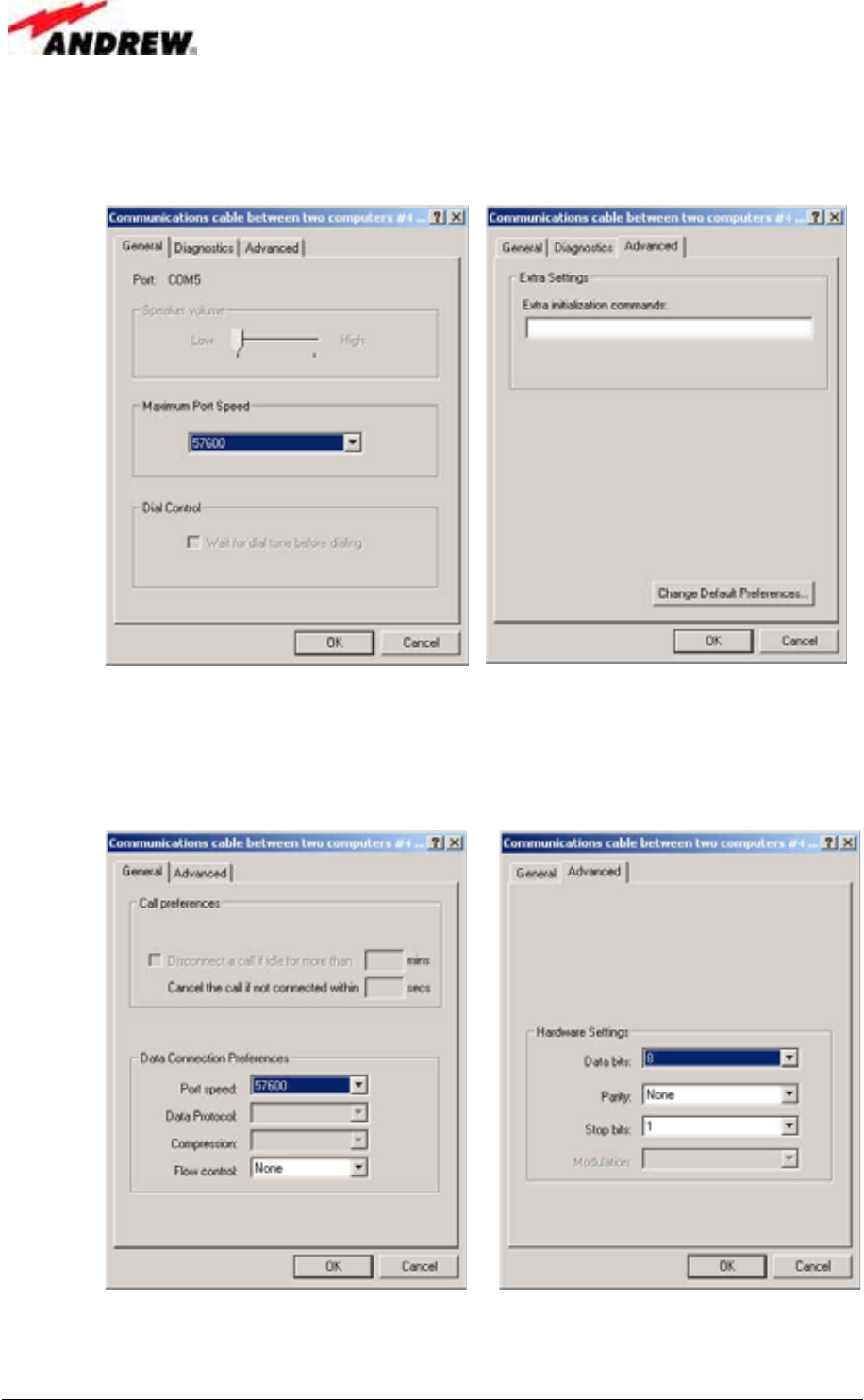
6. In the General tab, change the port speed to 57600.
Click the Advanced tab.
Click the Change Default Preferences tab.
7. Set the Port speed to 57600 and the Flow control to None.
Click the Advanced tab.
Set Data bits to 8.
Set Parity to None.
Set Stop bits to 1.
8. Click OK several times to exit all the windows. The modem configuration is
now complete.
4 Commissioning
ID No: 161692 PRELIMINARY Page 51
b) Setting up a direct connection
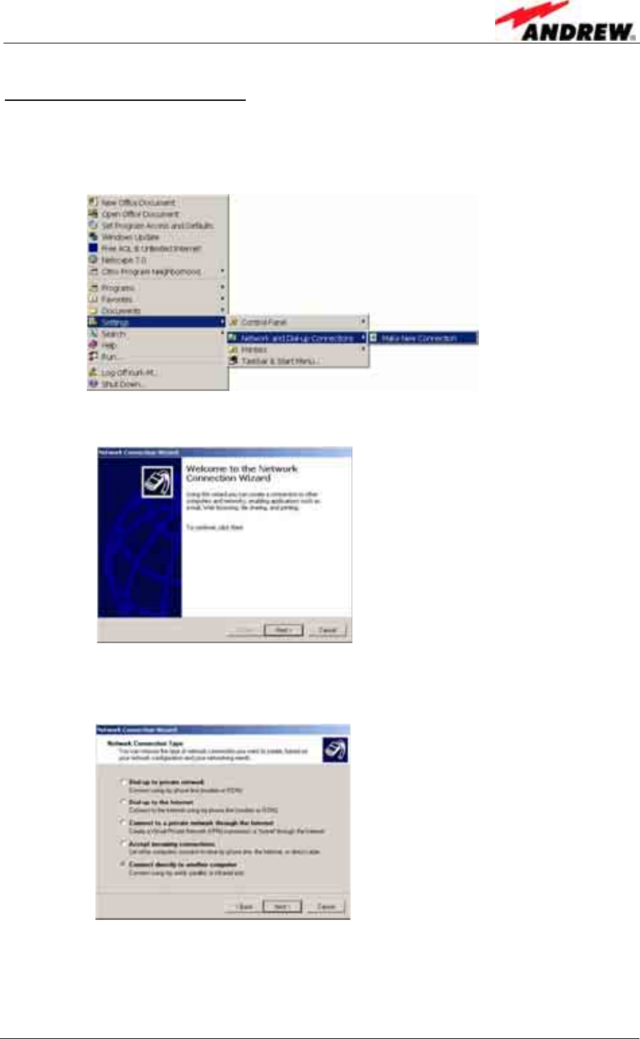
1. Start the Network Connection Wizard.
Click Start→Settings→Network and Dial-up Connections
→Make New Connection.
2. The first window is the Welcome window as shown below. Click Next.
3. The next window is Network Connection Type.
Select Connect directly to another computer. Click Next.
User’s Manual for Node C Network Elements
Page 52 PRELIMINARY M0121A1A_uc.doc
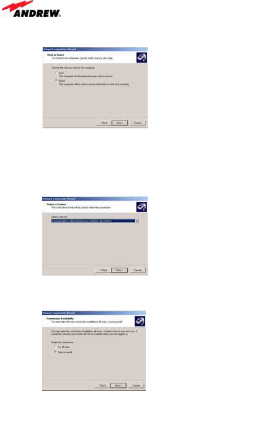
4. The next window is Host or Guest.
Choose Guest. Click Next.
5. The next window is Select a Device.
This window will provide a drop-down list of known communication ports
(devices) to choose from. Choose a serial port. If the RS232 is used, this port
is most likely (COM1). If a USB port is used some other COM port number
should be used. Take care that the USB driver is installed and connected
before completing this selection or the connection will not work.
Click Next.
6. The next window is Connection Availability.
Choose Only for myself. Click Next.
4 Commissioning
ID No: 161692 PRELIMINARY Page 53
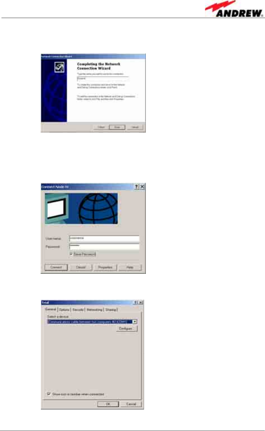
7. The next window is the Complete the Network Connection Wizard.
Enter Node C as the name for the connection.
Click Finish.
8. The next window is the Connection window
Enter <username> in the User Name field.
Enter <password> in the Password field.
Check Save Password.
Click Properties.
9. Under the General tab ensure the correct device is selected.
Click Configure.
User’s Manual for Node C Network Elements
Page 54 PRELIMINARY M0121A1A_uc.doc
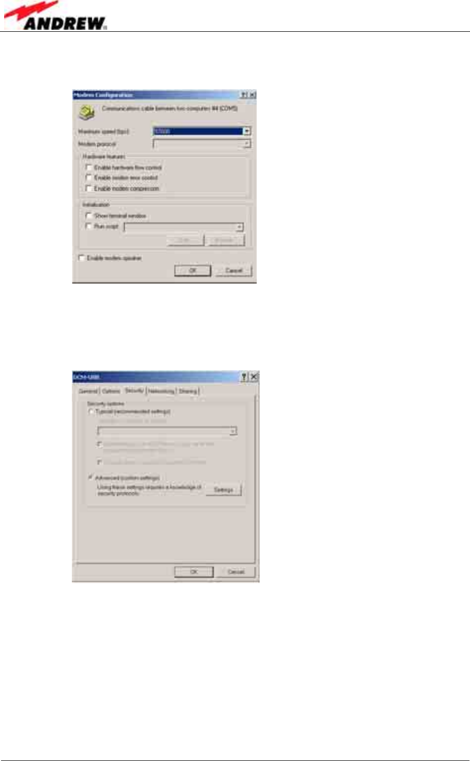
10. Choose 57600 for Maximum speed. All other boxes should not be checked.
Click OK.
11. Click the Security tab.
Click Advanced (custom settings).
Click Settings.
4 Commissioning
ID No: 161692 PRELIMINARY Page 55
12. Make sure Challenge Handshake Authentication Protocol (CHAP)
Microsoft CHAP (MS-CHAP)
Microsoft CHAP Version 2 (MS-CHAP v2)
are checked and all the rest of the boxes are NOT checked.
Click OK.
13. Click Typical and choose Require secured password.
User’s Manual for Node C Network Elements
Page 56 PRELIMINARY M0121A1A_uc.doc
14. Click the Networking tab.
Click the Settings button. There are 3 PPP settings. Make sure they are all
OFF. Click OK on the PPP Setting window.
15. Highlight the Internet Protocol (TCP/IP) component.
Click the Properties tab.
Click Obtain an IP address automatically.
Click Obtain DNS server address automatically
Click Advanced.
4 Commissioning
ID No: 161692 PRELIMINARY Page 57
16. In the General tab, uncheck all boxes.
In the DNS tab, make sure Append primary and Append parent and
Register this connection are checked.
17. Click the WINS tab. Make sure Enable LMHOSTS lookup is checked.
Click the Options tab. Click Properties.
User’s Manual for Node C Network Elements
Page 58 PRELIMINARY M0121A1A_uc.doc
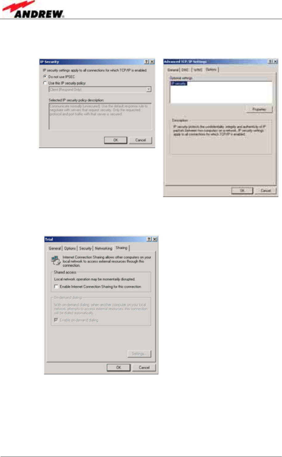
18. Click Do not use IPSEC.
Click OK.
Returning to the Options tab click OK and return back to the main window.
19. Click the Sharing tab.
Make sure that Shared access is OFF.
Click OK.
4 Commissioning
ID No: 161692 PRELIMINARY Page 59
c) Establishing the connection
1. Click Start→Settings→Network and Dial-up Connections→Node C.
The properties of this connection should already have been setup.
Enter <username> in the User Name field.
Enter <password> in the Password field.
Check Save Password.
Click Connect and the following connection windows will appear.
2. When the connection is successful an icon will appear in the system tray. This
icon will “light up” to indicate network activity between the computer and the
Node C. To check the status of the connection, click on the icon.
3. Please continue with chapter 4.2.3.6 Accessing the web page.
User’s Manual for Node C Network Elements
Page 60 PRELIMINARY M0121A1A_uc.doc
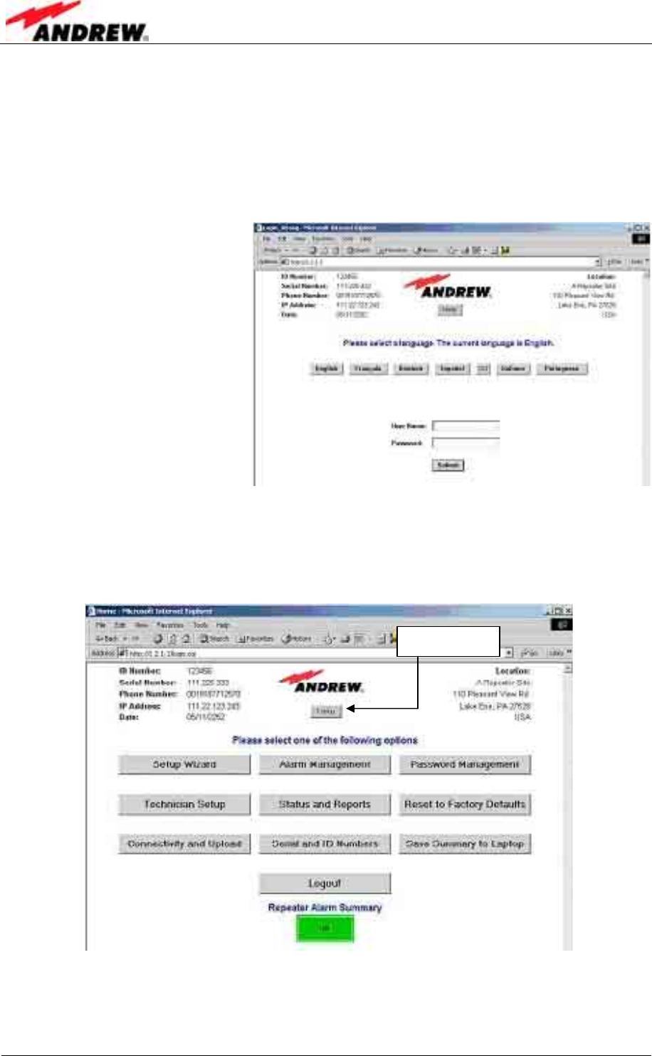
4.2.3.6 Accessing the web page
1. Open Internet Explorer and enter the address: 1.2.1.1.
Enter <Node_M> in the User Name field.
Enter <Golden_Node> in the Password field.
Note that these fields are case-sensitive.
2. After the login, the home page will appear. From this page the entire Node C may
be controlled. The most important menus will be explained in the following
chapter. For any further details click the Help button (also available in all of
the menus), to open the online help screens.
figure 4-4 Home page of web interface
The next chapter contains an explanation of the most important menus.
Help button

4 Commissioning
ID No: 161692 PRELIMINARY Page 61
4.2.4 Main Menus of the Web Page
For detailed information about a menu click the “Help” button to open the online help.
4.2.4.1 Setup Wizard
This menu serves to align the donor antenna and provides overviews of all channels
on air as wells as channel assignment.
figure 4-5 Setup Wizard
Antenna Alignment Assistant:
The intent of these web pages is to help the user correctly orient the antenna by
displaying the total received power in the selected 5MHz band and the power of the
strongest pilots within the 5MHz channel.
a) To start the Antenna Alignment Assistant (AAA):
1. Select ‘Setup Wizard‘ from the main page.
2. Select ‘Antenna Alignment Assistant‘.
3. Select the desired 5 MHz channel by using the dropdown box.
4. Select ‘Start Alignment’.
5. Observe the Rx DL Power and Pilot RSCP measurements and orient the antenna
to maximize performance.
6. Click ‘Home’ when completed.

User’s Manual for Node C Network Elements
Page 62 PRELIMINARY M0121A1A_uc.doc
b) Typical Tuning Procedure (See example table below):
1. Point the donor antenna in the general direction of the donor base station.
2. Start the AAA.
3. Verify that the reported DL Rx Power is above –90dBm. If not, orient the antenna
until the signal is above –90dBm.
4. Wait for Pilot RSCP results to be reported (indicating that a valid pilot has been
found).
5. Verify that the ARFCN and frequency reported at the top of the table matches the
ARFCN and frequency of the donor base station.
6. Orient the antenna to maximize the Pilot RSCP from the donor base station.
Usually, the best method is to course-tune the antenna based on DL Rx Power
measurements and then fine-tune based on Pilot RSCP measurements.
However, if multiple pilots are present, then using the DL Rx Power
measurements alone may not work well, and the user will have to rely on Pilot
RSCP only.
7. If multiple rays are present, then it is usually best to orient the antenna to
maximize the level of the first ray (the line-of-sight – or LOS – signal). However, if
the first ray is not the strongest signal, then there is an obstruction in the LOS
signal, and the strongest signal is a multipath component. This may mean that the
donor signal is prone to fluctuation, resulting in sub-optimal performance of the
unit.
Assisted Antenna Tuning
Channel 12345 , 2100 MHz
DL Rx
Power
(dBm)
RSCP of
Pilot 111
(dBm)
RSCP of
Pilot 111
(dBm)
RSCP of
Pilot 333
(dBm)
RSCP of
Pilot 444
(dBm)
Multipath
Componen
t 1st Ray 2nd Ray 1st Ray 1st Ray
-80 - - - -
-80 - - - -
-80 -91 -92 -93 -94
-80 - - - -
-80 - - - -
-80 - - - -
-80 -91 -92 -93 -94
-80 - - - -
-80 - - - -
-80 - - - -
-80 -90 -91 -92 -93
-80 - - - -
-80 - - - -
-80 - - - -
-80 -90 -91 -92 -93
table 4-1 Assisted antenna tuning

4 Commissioning
ID No: 161692 PRELIMINARY Page 63
c) Notes on the AAA Measurement Results:
1. The DL RX Power is the total power in the selected 5 MHz channel. The DL Rx
Power measurement is updated approximately once per second.
2. The Pilot Received Signal Code Power (RSCP) measurements are updated
approximately once every four seconds after the antenna assistant finds a valid
pilot channel within the selected 5MHz bandwidth. It may take up to one minute to
perform the initial scan and report Pilot RSCP results.
3. The most recent results are displayed in the first row, and previous results move
down one row in the table.
4. Data is columnized based on the most recent pilot measurement results.
5. The pilot measurements display up to the four strongest rays. The measurement
result could show one pilot with four rays, two pilots with two rays each, one pilot
with three rays and one pilot with one ray, or four pilots with one ray each (or
fewest results if no additional pilots are found).
6. Multiple rays of the same pilot will be shown if the weaker rays are within 10dB of
the strongest ray.
7. The Pilot RSCP data is sorted based on the total power of all multipaths for each
particular scramble code. For instance, if one pilot has two rays, each at –63dBm
(for a total power of -60 dBm), they will be listed first if all other pilots are less than
-60 dBm.
8. If two or more multipath signals are received, then the power of each ray will be
displayed in order of arrival. The first ray is the line of sight signal and should be
the strongest. However, it is possible for the later rays to be stronger.
4.2.4.2 Connectivity and Upload
This page serves to
upload new software
(press the Upload
Software button and
follow the instructions)
and for entering the
modem settings for
OMC communication.
figure 4-6 Connectivity and Upload menu
User’s Manual for Node C Network Elements
Page 64 PRELIMINARY M0121A1A_uc.doc
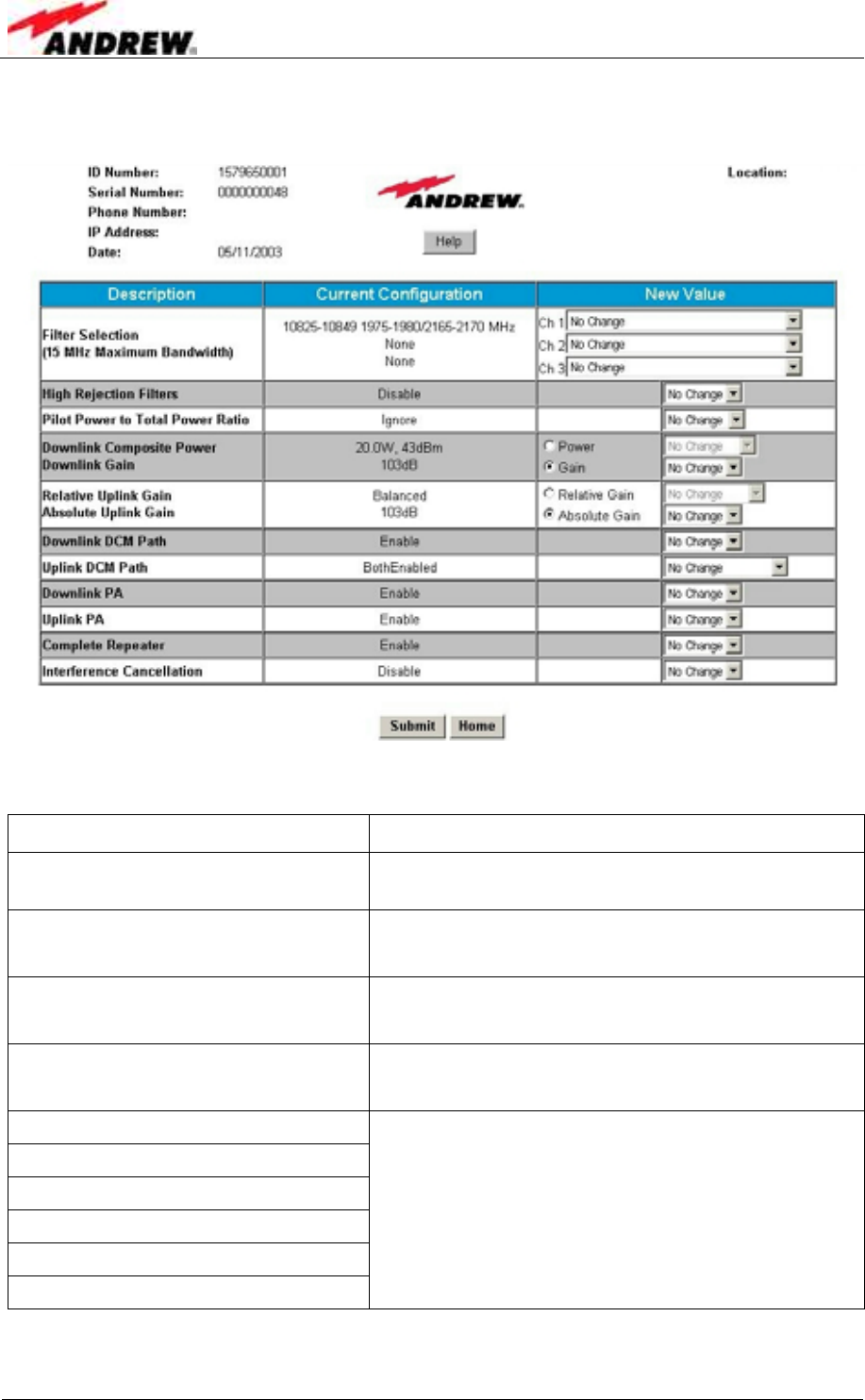
4.2.4.3 Technician Setup
figure 4-7 Technician Setup menu
Description Explanation
Filter Selection Select the frequency range for channel 1, 2 and
3; for filter setting refer to chapter 5.2.1 Filters.
Filter Power to Total Power Ratio Enter ratio of pilot power to total power
(depending on base station).
Downlink Power
Downlink Gain Select Power mode or Gain mode and set the
desired power or gain, respectively.
Relative Uplink Gain
Absolute Uplink Gain Select Relative or Absolute Uplink Gain mode
and set the respective value.
Downlink DCM path
Uplink DCM path *
Downlink PA
Uplink PA
Complete Network Element
Interference Cancellation
Enable or disable the respective feature.
* In the Uplink DCM path it is possible to enable or disable the primary and diversity paths
individually.
4 Commissioning
ID No: 161692 PRELIMINARY Page 65
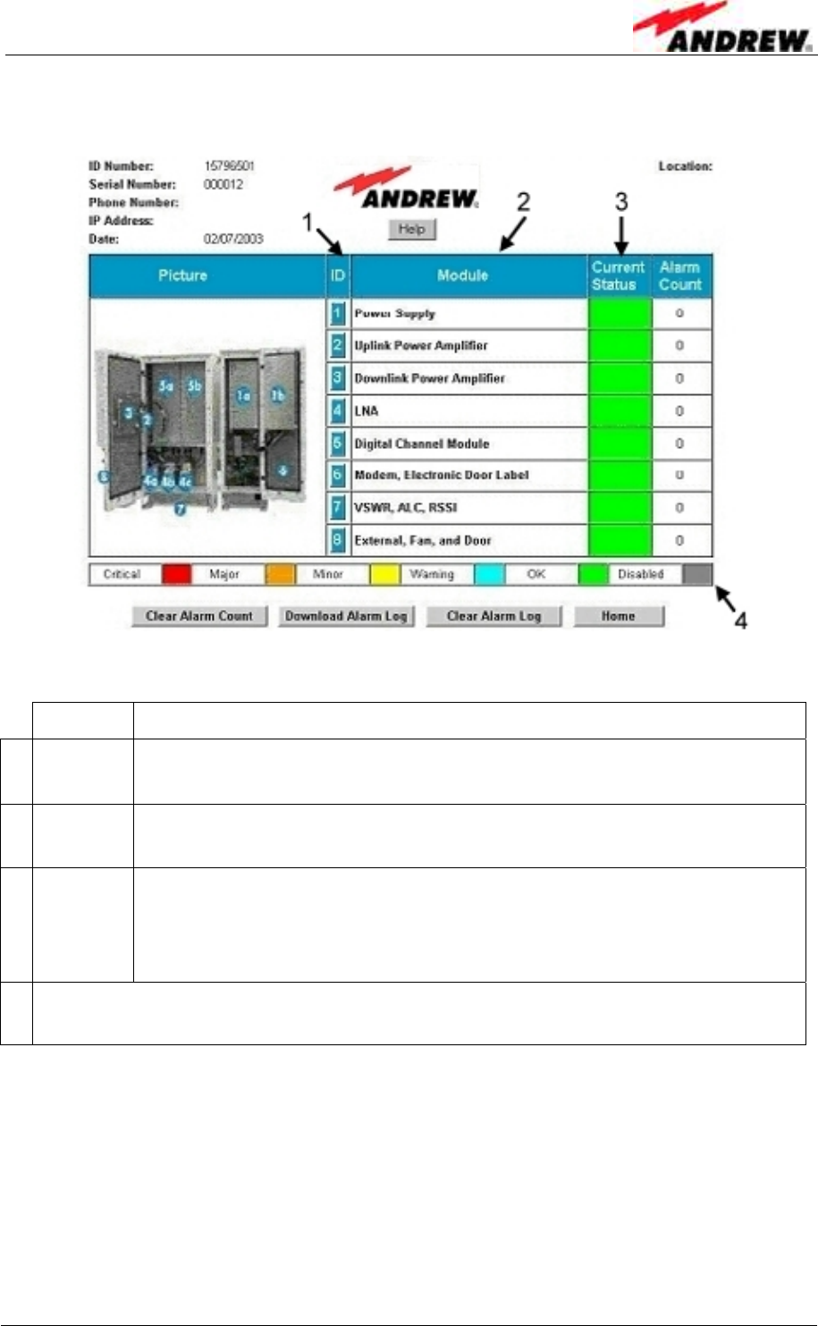
4.2.4.4 Alarm Management
figure 4-8 Alarm Management menu
Column Description
1 ID Clicking any of the number buttons opens a submenu * for the
respective component/feature.
2 Module All components and features listed in this column can be monitored
via software.
3 Current
Status
The cell colour (see [4] below) indicates whether an alarm is active. If
more alarms of different severity levels are active simultaneously
(number of alarms is displayed in column “Alarm Count” to the right),
the cell will always show the highest level that is active.
4 This row illustrates the colours by which the individual severity levels are
represented in column 3.
* This submenu includes an overview of the alarms available for the respective
component/feature and alarms can be disabled. In the column “Alarm Group” the
severity level for each alarm can be set. The possible severity levels are illustrated
under [4].
In the submenu for “VSWR, ALC, RSSI” [7] it is also possible to set the alarm
threshold (level at which an alarm will released) for these features.
Use the submenu [8] for “External, Fan and Door” for naming the external alarms.
User’s Manual for Node C Network Elements
Page 66 PRELIMINARY M0121A1A_uc.doc
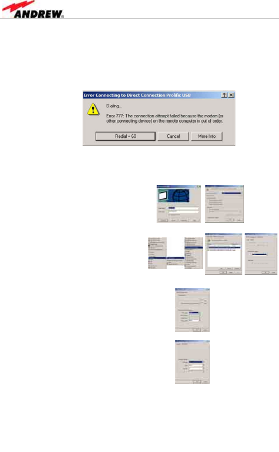
4.3 TROUBLESHOOTING
Connection Problem:
After clicking Connect, the progression goes from Dialling to a Connection Error as
shown below.
Possible Solutions:
I. The connection is not configured properly.
a. Click Properties→Configure in the
Direct Connection window.
Make sure Speed is set at 57600.
Make sure no flow control is checked.
b. Click Start→Settings→Control Panel→
Phone and Modem Options.
Go to the Modem tab.
Highlight the used modem connection.
Click Properties.
In the General tab set the Speed to 57600.
c. Click Advanced.
Click Change Default Preferences.
Click on the General tab.
Make sure Speed is set to 57600.
Make sure Flow Control is set to None.
d. Click Change Default Preferences
Make sure Data Bits are set to 8.
Make sure Parity is set to None.
Make sure Stop Bits is set to 1.
Click OK to exit.
II. The physical connection is loose.
4 Commissioning
ID No: 161692 PRELIMINARY Page 67
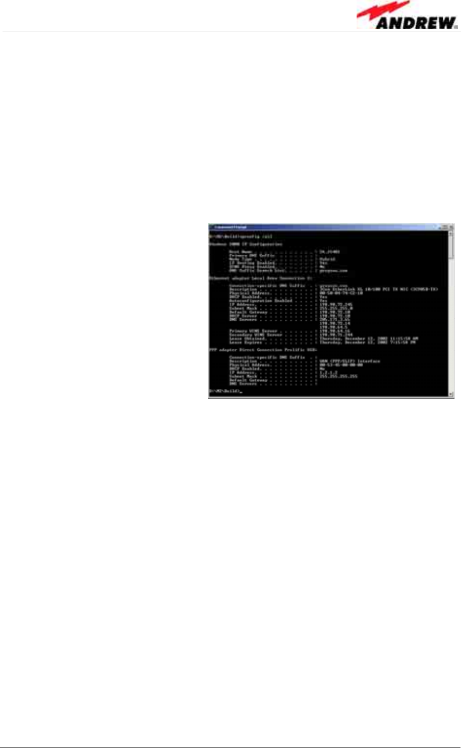
Connection Problem:
After entering the Node C address, an HTTP error page is returned instead of the
login page.
Possible Solution:
I. If the computer is connected to another network, the HTTP request may be going
out to that network instead of to the Node C. This is likely if after entering the Node
C address, the Direction Connection icon does not light up with activity.
a. Click Start→Run
Type cmd to get a dos prompt.
Type ipconfig /all
b. To release the LAN
Type Click ipconfig /release.
c. Click the Direct Connection icon
Click Disconnect.
d. Close Internet Explorer.
e. Restart the connection procedure.

User’s Manual for Node C Network Elements
Page 68 PRELIMINARY M0121A1A_uc.doc
For your notes:
5 Functional Description
ID No: 161692 PRELIMINARY Page 69
5 FUNCTIONAL DESCRIPTION
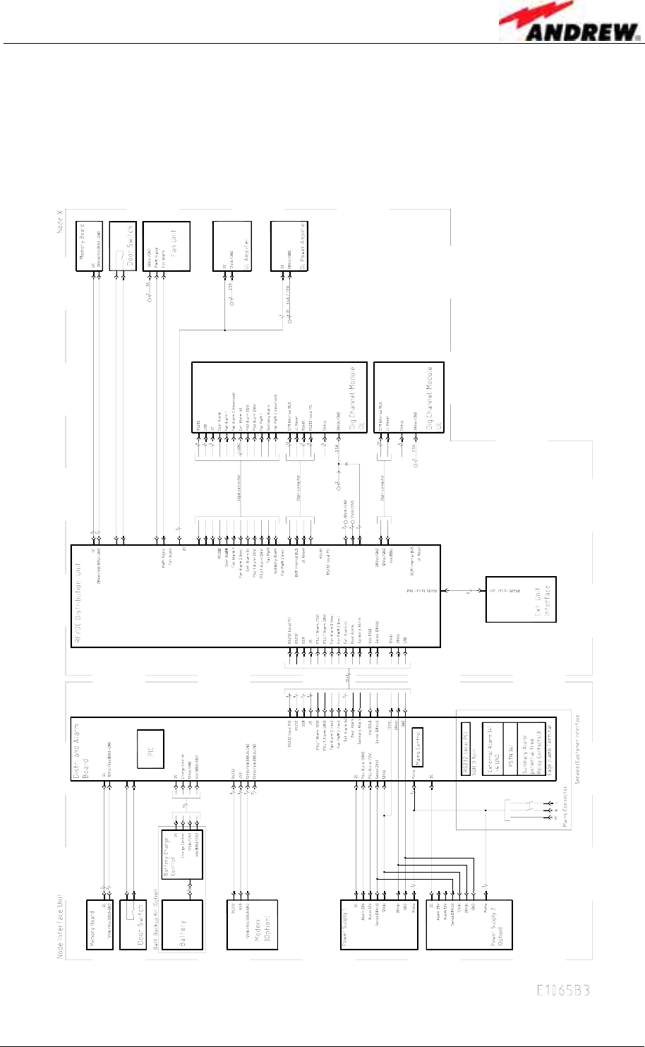
5.1 GENERAL
The following figure shows the DC block diagram of the Node C.
figure 5-1 DC block diagram of a Node C
User’s Manual for Node C Network Elements
Page 70 PRELIMINARY M0121A1A_uc.doc
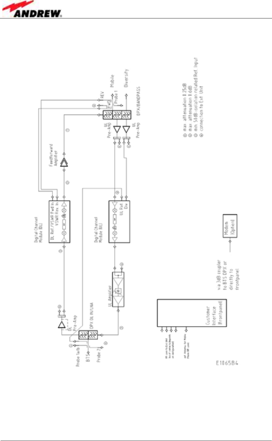
The following figure shows the RF block diagram of the Node C.
figure 5-2 Configuration of a Node C network element
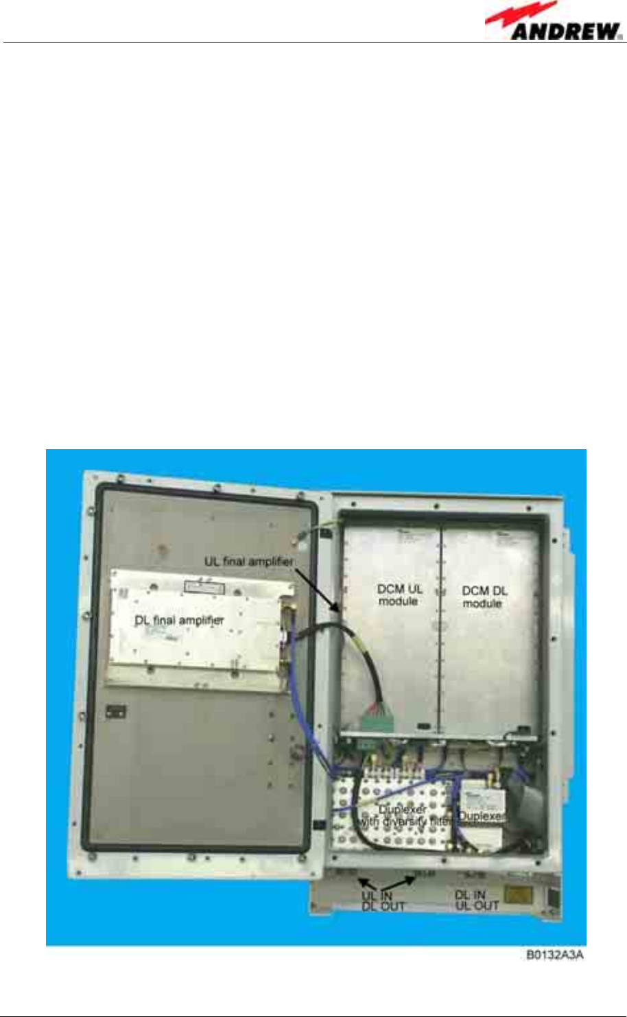
The Node C is designed to amplify signals between multiple mobiles and a base
station in a CDMA system. The unit consists of a filter and amplifier chain in the
downlink and one or two filters and amplifier chains in the uplink (primary and
diversity). The uplink and downlink paths are connected via a duplexer on both ends
of each path.
5 Functional Description
ID No: 161692 PRELIMINARY Page 71
In the primary uplink path, a signal originating from the mobile is separated from the
downlink signal via the primary UL IN duplexer. It is then amplified by an integrated
low noise amplifier (LNA) and forwarded to the uplink digital channel module (DCM).
The DCM down-converts the signal to base-band, digitally filters it, amplifies it and
then up-converts it. In addition the interference cancellation technology is
implemented in the DCM. Finally, the signal is sent to the final amplifier and
combined with the downlink input signal in the DL IN duplexer. The optional diversity
uplink path (via a second filter) is identical except signals enter via the diversity UL IN
duplexer and are combined in the DCM with the primary path.
In the downlink path, a signal originating from the base station is separated from the
uplink signal in the DL IN duplexer. It is then amplified by an integrated low noise
amplifier (LNA) and forwarded to the downlink digital channel module (DCM). The
DCM down-converts the signal to base-band, digitally filters it amplifies it and then
up-converts it. In addition the interference cancellation technology is implemented in
the DCM. Finally, the signal is sent to the final amplifier and combined with the uplink
input signal in the primary UL IN duplexer. The downlink DCM is also responsible for
communication and control of the entire unit. Using a Node C 1943 as an example,
the following figure illustrates the positions of the RF components inside the Node C.
figure 5-3 RF path of a Node C, exemplary
User’s Manual for Node C Network Elements
Page 72 PRELIMINARY M0121A1A_uc.doc
5.2 FEATURES OF THE NODE C
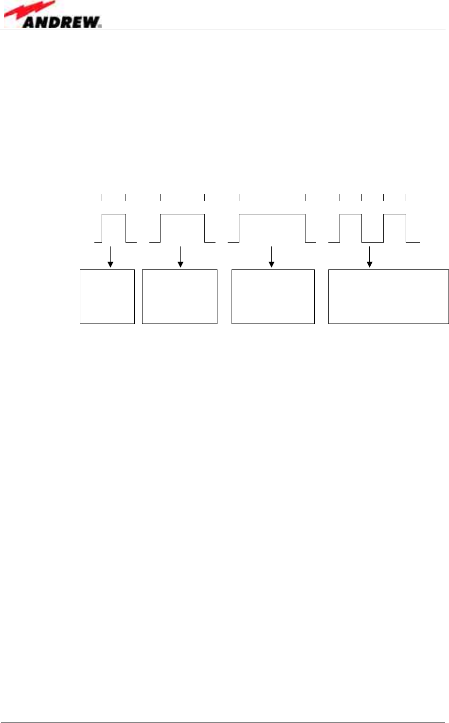
5.2.1 Filters
Filters are set automatically according to the channels set in “Setup Wizard” or
“Technician Setup”. For further information about these menus refer to chapters
4.2.4.1 and 4.2.4.3.
Possible filters are: 5 10 15 5 5 5 MHz
and
, ,
One
WCDMA
channel
two adjacent
WCDMA
channels
three adjacent
WCDMA
channels
two WCDMA
channels;
intermediate channel
not used
5.2.2 Digital ICE (Digital Interference Cancellation Equipment)
Digital ICE has been developed to enhance antenna isolation. This feature enables
the Node C to provide coverage in areas where effectivity is decreased due to
physical site limitations which cause insufficient antenna isolation.
Antenna isolation is the RF loss measured between the donor antenna and the
coverage antenna. If the gain of the network element exceeds the path loss,
feedback in form of oscillation occurs. The isolation is usually dominated by the direct
path loss from one antenna to the other, but reflections can contribute to or even
affect antenna isolation. Digital ICE cancels the signal from the primary feedback
path, thus allowing the gain of the network element to be increased.
The required delay resulting from the on-site conditions is measured by the DCM
module and set accordingly.
For software setting commands please refer to the online help screens.
The Digital ICE function can be enabled or disabled in the “Technician Setup” page
(see chapter 4.2.4.3). Isolation and gain margin* can be checked in the “Status and
Reports” menu accessible via the home page of the web interface (see figure 4-4).
* gain margin = antenna isolation minus Node C gain

5 Functional Description
ID No: 161692 PRELIMINARY Page 73
5.2.3 VSWR (Voltage Standing Wave Ratio)
This feature enables the provider to query the status of the antenna system (antenna
& cable). The voltage standing wave ratio of the DL output antenna port is measured.
If the VSWR falls below the value set in the “Alarming Management” (see chapter
4.2.4.4), an alarm is released. The alarm can be forwarded to the OMC where the
faults and irregularities can be acknowledged and eliminated promptly.
The current VSWR value can be checked in the “Status and Reports” menu
accessible via the home page of the web interface (see figure 4-4).
5.2.4 RSSI (Receive Signal Strength Indication)
The RSSI provides controlling and monitoring of the receive level of a base station
(DL RSSI) or user equipment (UL RSSI) to a Node C. It measures the level of the
input signal by detecting the RF and converting the analogue level into a digital
value. The data are processed and evaluated by software. An alarm will be released
if the measured signal level exceeds the alarm level set by the provider via software.
) Note: If the Node C is equipped with a diversity path, both values will be
combined before the RSSI evaluation. Thus, only one UL value is
reported.
The current RSSI values can be checked in the “Status and Reports” menu
accessible via the home page of the web interface (see figure 4-4).
5.2.5 Alarmforwarding
Alarms can be forwarded to a defined phone number or to the OMC if the Node C is
equipped with a modem or a mobile station. This enables the provider to control and
to query the status of the network. Faults and irregularities can be recognized and
eliminated.
With an optional modem the Node C also provides an SMS feature, by which the unit
is able to send out alarm messages as SMS. For further details please contact your
supplier.
User’s Manual for Node C Network Elements
Page 74 PRELIMINARY M0121A1A_uc.doc
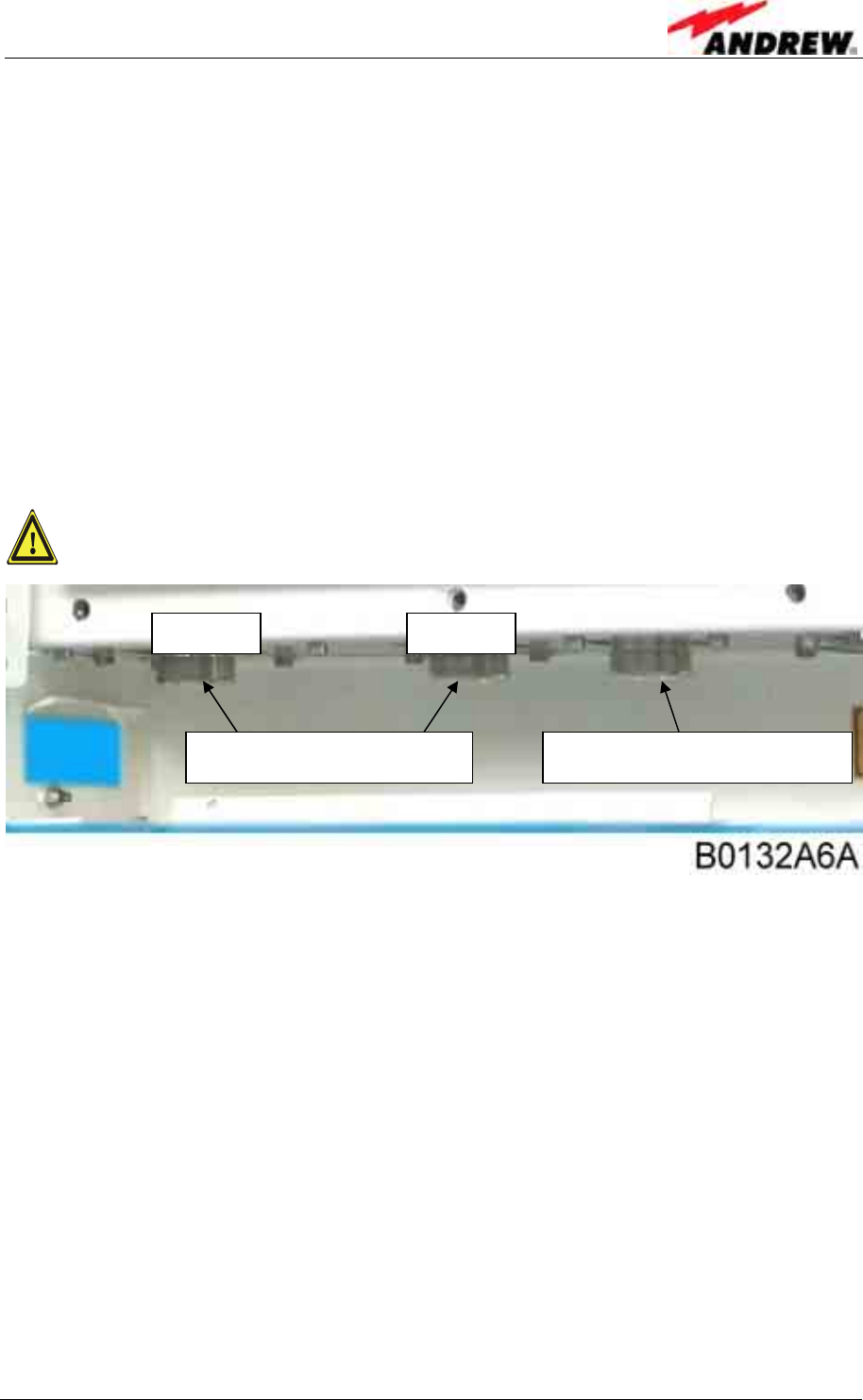
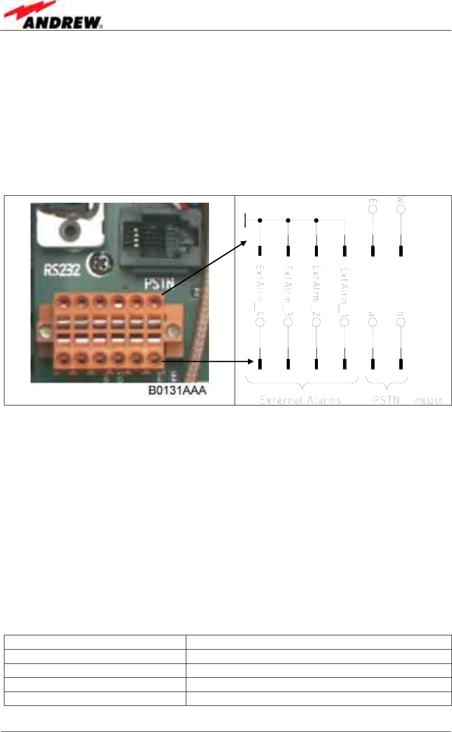
5.2.6 External Alarms
The external alarms are used to monitor the status of one or more external devices
via the Node C. A UPS or entry alarm is among the items that might be connected to
the contact relay and monitored via the Node C. The cage clamp connectors are
located on the distribution & alarm board of the Interface Unit.
Observe that the cross-sectional area of the wires to be connected must be in the
range from 0.5 - 1.0 mm2. Do not use wire-end sleeves (wire cable ends).
figure 5-4 Configuration of external alarm clamps
There are three external cage glands at the bottom of the Interface Unit, which may
be used to connect the external devices.
All external alarms are defaulted to high (5VDC) without connection. This setting may
be changed on the external alarm page to active high or active low. The severity
levels of the external alarms may be set via the web page. More information about
the external alarm settings is available in the web page and online-help.
When not all of the external alarms are required, make sure that the other alarms are
set to active low or disable the alarm; otherwise the status will always show an alarm.
The names for each external alarm are user-definable on the external alarm page
(see chapter 4.2.4.4 Alarm Management) and it is suggested that they be renamed to
indicate the use of these alarms.
Input voltage range 5VDC
Recommended input line Potential free
Nominal sink current to ground 15mA
Active level High or low set via software
Connectors Cage clamps
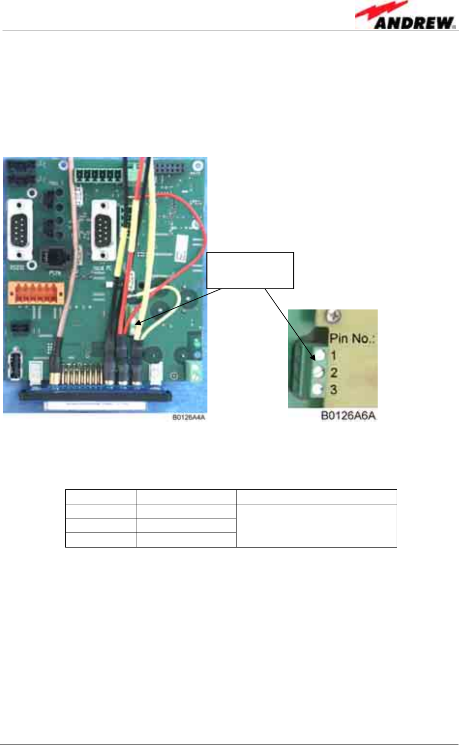
5 Functional Description
ID No: 161692 PRELIMINARY Page 75
5.2.7 Summary Alarm
The summary alarm is a DC insulated contact relay.
Observe that the cross-sectional area of the wires to be connected must be in the
range from 0.14 - 1.5 mm2.
figure 5-5 Summary alarm relay
The following table indicates the three-connector pin out.
Pin No. Contact Maximum Resistive Load
1 Normally closed Max 1A @ 50VDC
2 Common Max 2A @ 30VDC
3 Normally open Max 1A @ 230VAC
Summary alarm
relay contact
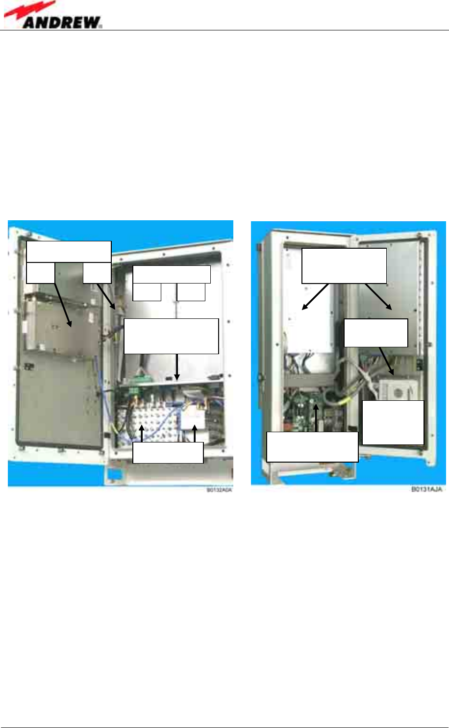
User’s Manual for Node C Network Elements
Page 76 PRELIMINARY M0121A1A_uc.doc
5.3 COMPONENTS OF THE NODE C AND INTERFACE UNIT
The actual configuration can be seen at the configuration list*, which is part of the
delivery.
The following figure shows a Node C 1943** (layout of Node C 843 is the same) and
an Interface Unit with PSU redundancy option (two power supplies).
* To be replaced by an electronic door label that will be accessible via software & remote control.
** The layout of a Node C x37 differs from the Node C x43 only in the design of the DL final
amplifier (see chapter 5.3.5 Downlink Final Amplifier).
figure 5-6 Layout of a Node C 1943 and Interface Unit
5.3.1 Duplexer
The duplexer is used to isolate the uplink from the downlink, i.e. to separate the
transmitting path from the receiving path. The pass band of the duplexer is the full 60
MHz of the CDMA band. This allows the same Node C to be used regardless of its
operator’s frequency plan.
The integrated LNAs (low noise amplifiers) are biased via the RF cable from the
DCM module. The DL/LNA can be bypassed for strong input signals by the DCM
module automatically.
Power supplies
(right: optional)
DCM modules
UL DL
Position of
optional
modem
Duplexers
Final amplifiers
DL UL
Distribution and
interface board
RF and DC
Distribution Unit CD for
US
B driver
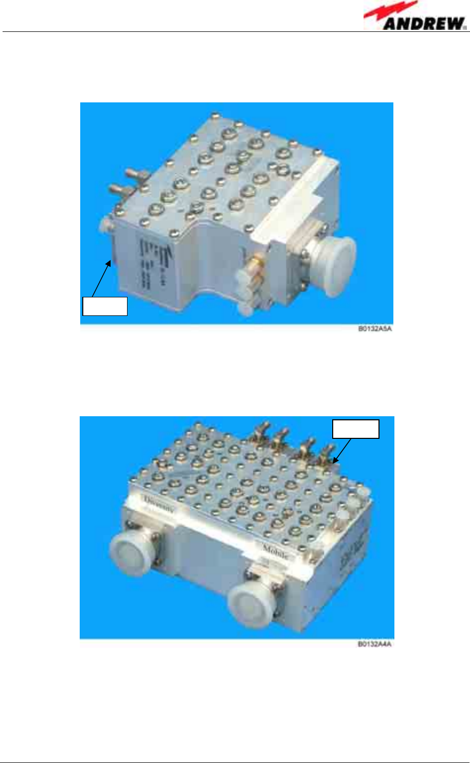
5 Functional Description
ID No: 161692 PRELIMINARY Page 77
The DL duplexer has multiple outputs, including the primary and extension path, plus
forward and reverse probes used for auto setup, VSWR, and RSSI functions.
figure 5-7 Duplexer, DL IN
The UL IN duplexer of the Node C is equipped with a diversity filter. The duplexer is
used for the primary uplink path and is shared with the downlink output.
figure 5-8 Duplexer, UL IN, with integrated diversity filter
The diversity filter is equipped to provide increased uplink signals in a multipath
environment. The two paths are combined inside the DCM maintaining a time delay
between both paths. According to measurements signal strength gain is about 3-5 dB
for diversity reception.
LNA
LNA
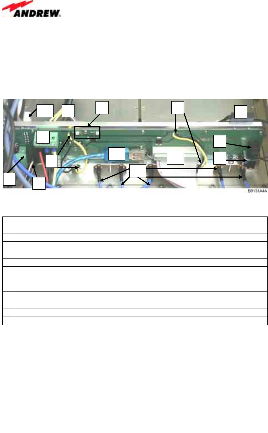
User’s Manual for Node C Network Elements
Page 78 PRELIMINARY M0121A1A_uc.doc
5.3.2 RF and DC Distribution Unit
The RF and DC distribution unit is mounted between the duplexers and DCMs.
It is the physical transport layer for communication between the downlink DCM
(which has the integrated controller) and other sub-components of the Node C (see
also chapter 3.2.5 Connection of Cable Bridge).
figure 5-9 RF / DC distribution unit
1 To cable bridge connector from Interface Unit for connection of 12V, GND, 28 V
2 DL-PA connector
3 LEDs for voltage indication (left: 28 V, right: 12V)
4 28 V to DCM modules
5 Door contact
6 Connector for door contact
7 RS485 connection to extension unit
8 Fan connector (NodeM 43)
9 Memory board connector
10 To cable bridge connector for USB connection from Interface Unit
11 To cable bridge connector from Interface Unit
12 RF cables
13 UL PA connector
table 5-1 Connections of RF / DC distribution unit
5
6
7
2
9
12
1
8
3 4
11
10
4
13
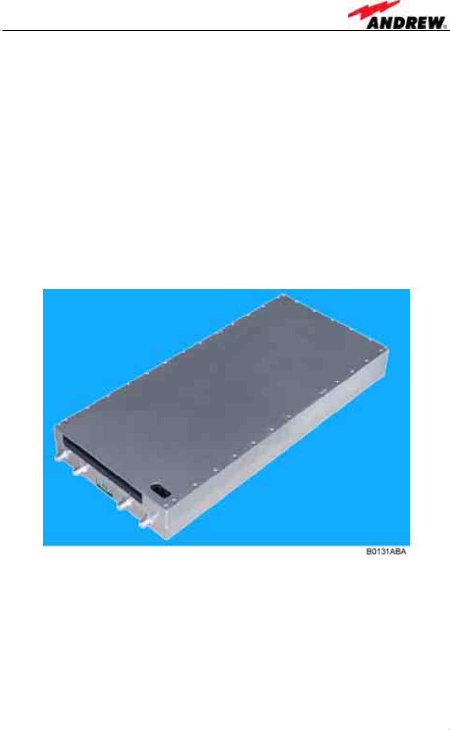
5 Functional Description
ID No: 161692 PRELIMINARY Page 79
5.3.3 Digital Channel Module (DCM)
The task of the digital channel module (DCM) is to filter and amplify any signals
passing through it. In addition it takes measurements of the input and output signals
and decodes the air interface to ensure proper setup and operation.
Finally it performs the interference cancellation algorithms, which eliminate the
normal problems associated with isolation, and has an integrated controller (in the DL
part) for the entire Node C, which maintains a web server for local and remote
communication. This process is accomplished by both analogue and digital means.
In case the diversity option is equipped, the module receives signals from both the
primary duplexer and diversity filter. Both signals are combined digitally and filtered
before being amplified in the uplink amplifier.
The DCM consists of an UL and DL part.
figure 5-10 DCM (UL or DL part)
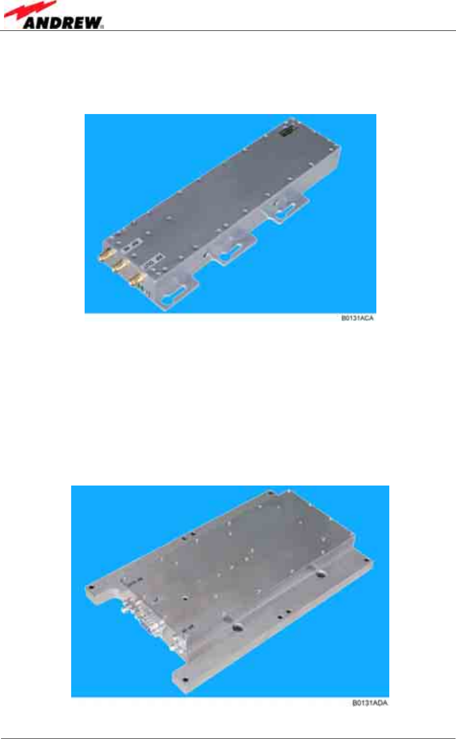
User’s Manual for Node C Network Elements
Page 80 PRELIMINARY M0121A1A_uc.doc
5.3.4 Uplink Final Amplifier
The UL path is amplified by a final amplifier for high output power.
figure 5-11 Uplink final amplifier
5.3.5 Downlink Final Amplifier
In the DL path, an error-correcting feed-forward amplifier, which has a high output
power while maintaining superior intermodulation and linearity performance, is used
as final stage.
In the Node C x37 a 37 dBm (2 W) average power final amplifier is used.
figure 5-12 Node C x37 DL final amplifier
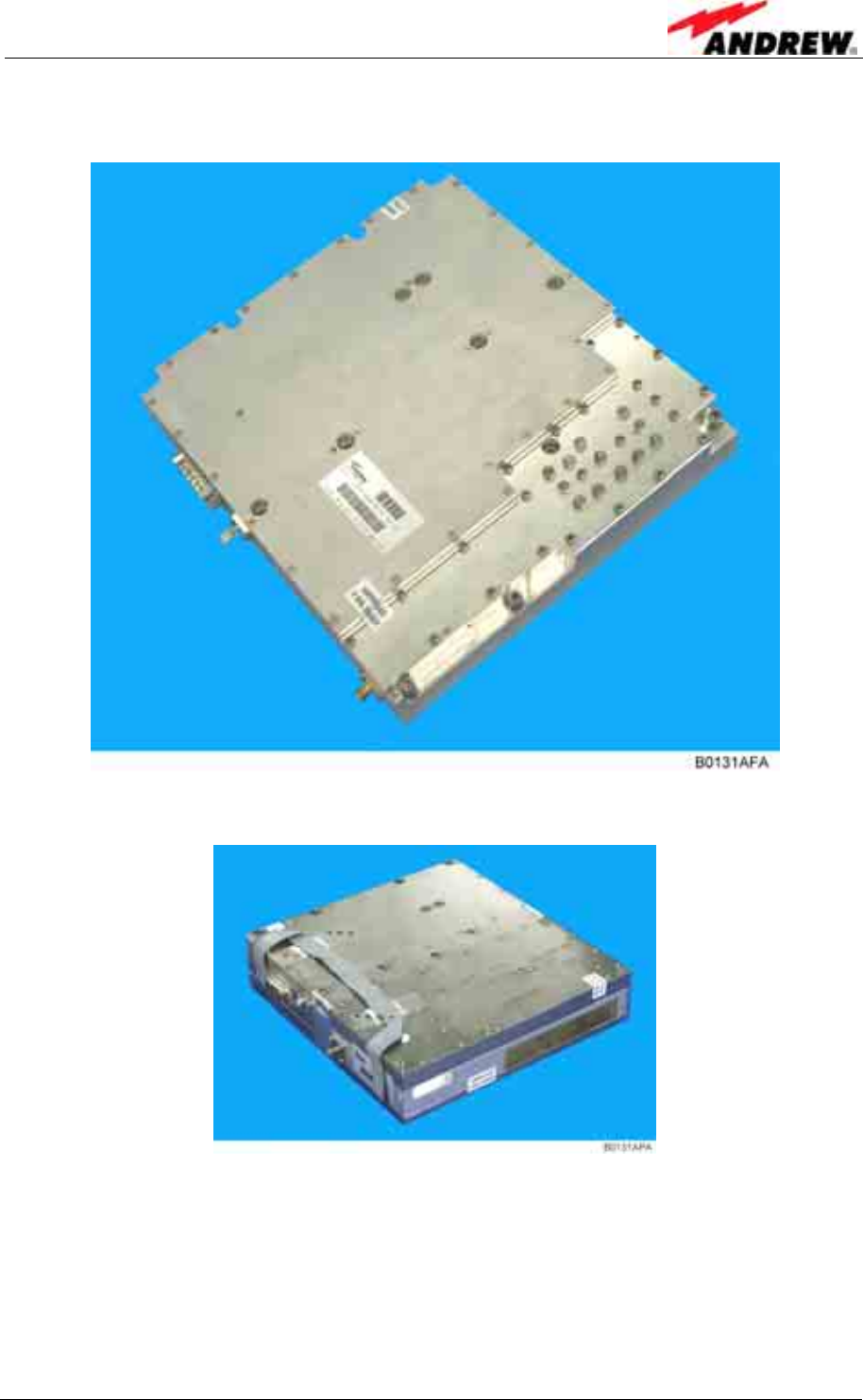
5 Functional Description
ID No: 161692 PRELIMINARY Page 81
In the Node C x43 a 43 dBm (20 W) average power final amplifier is used.
figure 5-13 Node C x43 DL final amplifier, new type
figure 5-14 Node C x43 DL final amplifier, former version
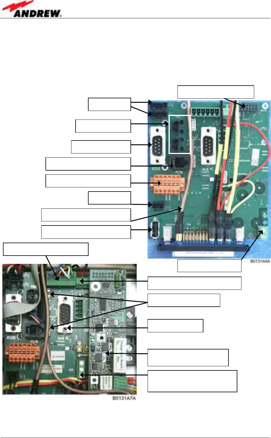
User’s Manual for Node C Network Elements
Page 82 PRELIMINARY M0121A1A_uc.doc
5.3.6 Distribution & Alarm Board
The distribution & alarm board of the Interface Unit is the main connection point for
the user. It has the external alarm clamps, RS232 connectors, for local or modem
connection, as well as a summary alarm relays. The following figures show one blank
board and an installed one with battery backup.
figure 5-15 Distribution & alarm board
* Only these connectors are for general customer use. All others are designated above for
informative purposes, and required, only, e.g. for an upgrade or replacement of parts.
Battery charge module
Internal I
2
C
Power supply alarming / I
2
C
Remote (RS232)*
Internal PSTN connector
External alarms & PSTN *
Door switch
Summary alarm*; see chapter
5.2.7 for pin assignment
Local (RS232) *
Battery backup connector
Vdc for modem *
USB connector for modem*
Mains surveillance
Battery load discharge (resistor)
Modem fuses (2.5 A)
Modem cable (RF connection)
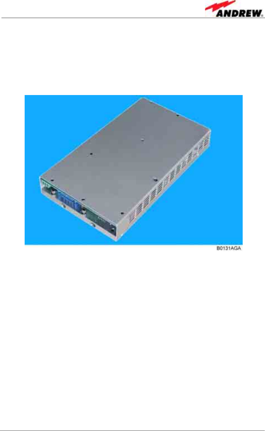
5 Functional Description
ID No: 161692 PRELIMINARY Page 83
5.3.7 Power Supply
The power supply, which is mounted in the Interface Unit, transforms AC mains
power into a predefined DC voltage. When performing maintenance, ensure that all
circuits are voltage-free and that the Node C is disconnected from mains.
The Node C may be equipped with a second power supply for redundancy.
figure 5-16 Power supply
5.4 OPTIONAL EQUIPMENT
The actual configuration can be seen at the configuration list*, which is part of the
delivery.
* To be replaced by an electronic list that will be accessible via software.
5.4.1 Modem with Battery Backup
The modem is used to establish a remote connection to the Node C. The connection
may be used to change the unit’s parameters, check and clear alarms or collect
measurement and quality statistics.
Furthermore, the modem is at the Node C’s request to alert the operator when there
is an alarm. The modem may be over-the-air (wireless) or PSTN. It is possible to
install the wireless modem or the PSTN modem on site.

User’s Manual for Node C Network Elements
Page 84 PRELIMINARY M0121A1A_uc.doc
À Check the communication mode between the modem and the terminal. The
following parameters should be set for a GSM modem.
Bit rate / bit per second: 9600 baud Number of data bit: 8 bit
Parity bit: No parity Stop bit: 1 stop bit
These settings may only be changed locally. Should a different modem be used, the
operator should ensure that the settings are changed prior to leaving the site.
5.4.1.1 Initstrings
The initialization string depends on the operator’s network and the modem. It may be
necessary to adjust the init string in the field. The following init string is factory set.
Modem Network Initstring
not yet available t.b.d.
via Node C Web Interface: t.b.d.
table 5-2 Standard initstring for modem
5.4.1.2 Wireless Modem
The wireless modem allows remote
control and maintenance of the Node C.
Parameters may be changed; alarm and
measurement statistics may be
acknowledged and collected in the
OMC.
The modem is installed in the cover of
the Interface Unit. The antenna
connector for the modem is located at
the connector panel of the Interface Unit
For technical data of the modem refer to
chapter 7.2.3 Specifications for Optional
Equipment.
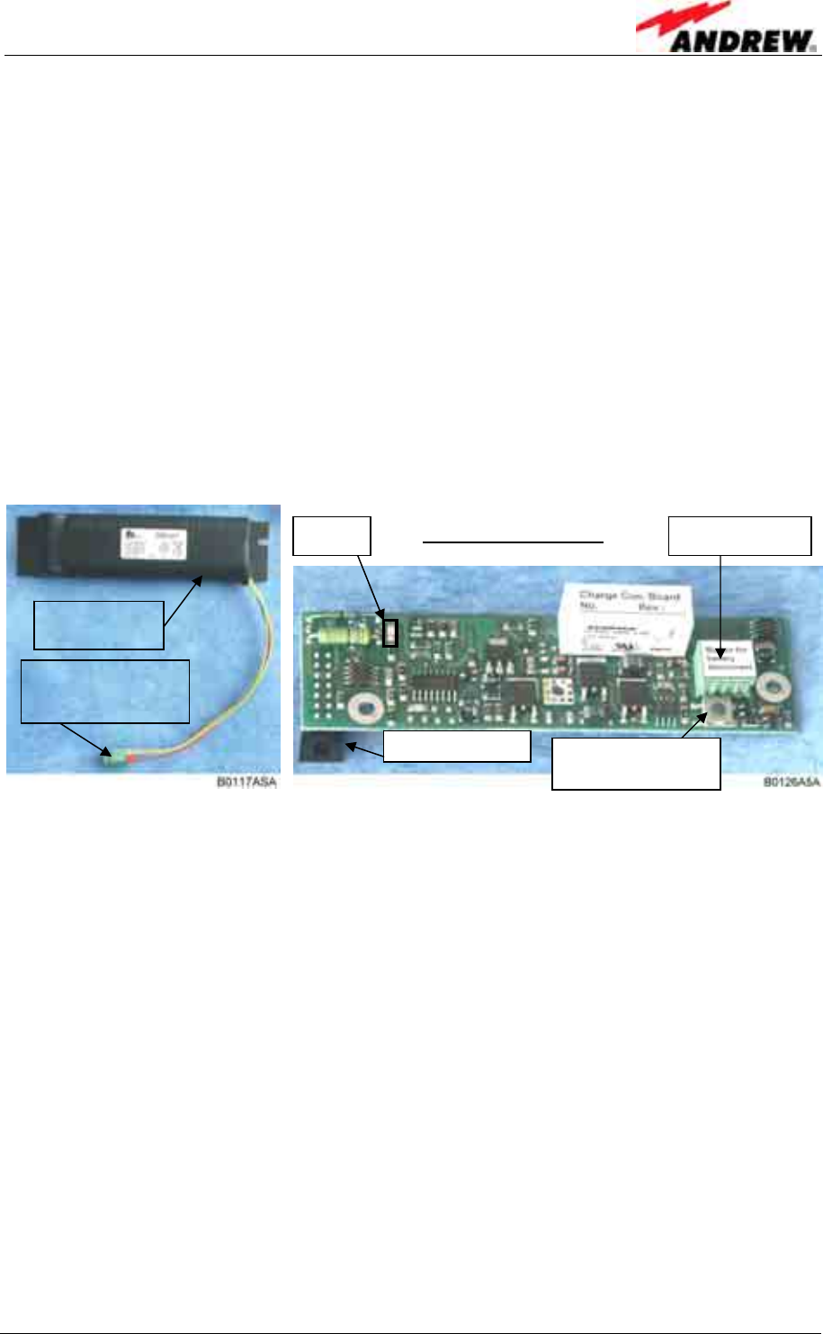
5 Functional Description
ID No: 161692 PRELIMINARY Page 85
5.4.1.3 Battery Backup
In case power fails, a battery backup system for controller and modem has been
implemented. This provides enough power for the controller that is integrated into the
downlink DCM and the modem to operate for a limited period of time (see chapter
7.2.3 Specifications for Optional Equipment for battery backup time). Within this time,
the Node C will initiate a call to the OMC and alert the operator that power has been
lost. All other functions will cease to work in case of power failure.
The battery packs are protected from deep discharge by use of a low voltage
disconnect unit. When performing preventive maintenance, make sure that all circuits
are voltage free by disconnecting the battery cable (C1) from its connector (C2). In
case of a power cycle, it is sufficient to press the “Battery disconnect button” to
interrupt the voltage supply. After mains is connected again, the battery will be
charged and the battery backup function will be activated automatically.
figure 5-17 Battery backup module, exemplary
The battery charge module is plugged directly onto the distribution & alarm board of
the Interface Unit through connector C3.
The battery pack should be discharged at regular intervals of about three months to
optimize its service life. This service discharge may be activated via software
depending on the software version. The time required for the discharge varies
depending e.g. on the charge status of the battery pack. A fully charged battery may
require up to some hours to be completely discharged. Consider this when activating
the discharge and also observe the following note.
) Note: Please be aware that the backup function is not available during
discharge. Thus, a primary voltage failure in that time will result in
a complete system shut-down.
It is recommended to replace the battery pack of the battery backup option after two
years of usage as a preventive measure. The nominal lifetime of the battery pack is
approx. two years under normal environmental conditions.
Battery pack
C1; to C2 of
charge module
Battery charge module
LED C2 connector
C3 connector Battery
disconnect button

User’s Manual for Node C Network Elements
Page 86 PRELIMINARY M0121A1A_uc.doc
When the battery is charging, an LED on the module turns on. When the battery is
fully charged, the LED will switch off.
The location of the battery backup parts are illustrated in figure 6-3 Location of
battery backup.
For technical data of the battery backup module refer to chapter 7.2.3 Specifications
for Optional Equipment.
5.4.2 PSU Redundancy
The Node C Interface Unit may be equipped with two power supplies. This
guarantees full power redundancy. The PSUs are interconnected by a current control
line for current load sharing with a ratio of approx. 50% to each supply.
Currently the PSU redundancy option is only available for Node C x37.
5.4.3 High Rejection Filter
This software option provides a highly sophisticated filter feature that can be
controlled via the “Technician Setup” menu of the web page (see figure 4-7
Technician Setup menu).

6 Maintenance
ID No: 161692 PRELIMINARY Page 87
6 MAINTENANCE
6.1 GENERAL
Read the health and safety warnings in chapter 1.2 Health and Safety Warnings.
) Note: The Node C does not require any preventative maintenance
measures.
It is only recommended to replace the battery pack of the battery backup option after
two years of usage as a preventive measure. The nominal lifetime of the battery pack
is approx. two years under normal environmental conditions.
In the event of a malfunction, the user should check the status of the antennas,
feeder cables, connectors, and mains power before replacing any components.
6.2 REPLACEMENT OF COMPONENTS
Read the health and safety warnings in chapter 1.2 Health and Safety Warnings.
Maintenance of the Node C should be performed on a FRU (Field Replaceable Unit)
basis only. Do not damage the warranty labels on the components, as this voids the
warranty.
The spare parts list contains only units that can be replaced without tuning or
complex soldering work. Those units are all components of the Interface Unit. Do not
replace any components inside the Node C itself.
) Note: Defect parts should only be replaced by original parts from the
supplier. All interventions inside the housing are at one’s own risk.
) Note: During maintenance ensure that the unit has been disconnected
from mains.
To open the cabinet of the Interface Unit, observe the instructions in chapter 4.1
General.
) Note: If the optional battery backup is installed, disconnect the battery
cable from the charge module connector as described in chapter
5.4.1.3 Battery Backup, to ensure that all circuits are voltage-free.
) Note: Before disconnecting any cables, label any unlabeled cables to
ensure correct reconnection, and check the switch positions of the
removed part to set the switches of the new part accordingly.
To replace a FRU, use the appropriate tools. The tools are provided along with the
equipment. Replacement tools may be ordered from the supplier. All screws have a
right-hand thread, turn the tool clockwise for tightening and counter-clockwise for
loosening.
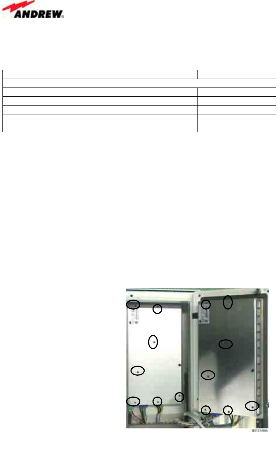
User’s Manual for Node C Network Elements
Page 88 PRELIMINARY M0121A1A_uc.doc
SMA connectors have a specified torque of 100 Ncm. Use an appropriate tool to
fasten and unfasten these. Do no over tighten the connectors or screws. The table
below shows various screws with their respective torques.
Screw Type Tallow-drop Socket head cap Countersunk head
Thread size Specified Torque (in Ncm)
M 2.0 40 not in use 40
M 2.5 82 not in use 82
M 3.0 145 100 145
M 4.0 330 330 330
M 5.0 650 tbd. 650
table 6-1 Specified torques for various screw types
) Note: Depending on the configuration of the Node C the FRU can be
equipped with a 50-Ohm termination resistor. In such a case, use
the termination resistor of the old FRU to terminate the respective
connector of the replacement part.
) Note: After the replacement of a component, check whether the system
has to be levelled anew.
) Note: Do not forget to reinstall the front cover after the replacement
procedure to ensure safe operation.
If any FRU not contained in the following chapter needs to be replaced, contact
customer service for additional instructions.
6.2.1 Power Supply
• To remove a power supply,
first disconnect all cables.
• Unscrew the seven M4
socket head cap screws by
which each power supply
is fastened to the cabinet.
• Use these screws to fasten
the new power supply and
reconnect all cables.
figure 6-1 Power supply screws
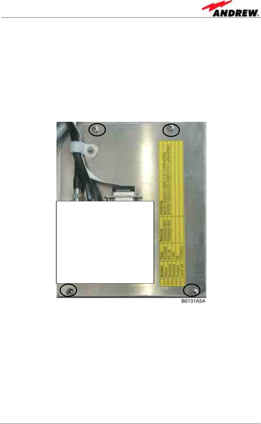
6 Maintenance
ID No: 161692 PRELIMINARY Page 89
6.2.2 Modem
The optional modem is screwed to a mounting plate which is fastened to the cabinet.
In order to separate the modem from the plate, the mounting plate has to be taken off
first.
• Before starting to remove the mounting plate, disconnect all cables.
• Then, unscrew the four tallow-drop screws M3x6 which fasten the mounting plate
to the cabinet.
figure 6-2 Mounting plate of modem
• Take off the plate with the modem attached. The modem is fastened from the back
to the plate with two countersunk head screws M4x10.
• Unscrew these screws and use them to fasten the new modem to the mounting
plate.
• Fasten the mounting plate again with the four tallow-drop screws M3x6 and
reconnect all cables.
Position of modem

User’s Manual for Node C Network Elements
Page 90 PRELIMINARY M0121A1A_uc.doc
6.2.3 Battery Backup
figure 6-3 Location of battery backup
• Before removing the battery charge module and battery, disconnect the
battery cable from the battery charge module (see also figure 5-17 Battery
backup).
• The battery can now be unplugged easily.
• Release the charger from the two snap connectors by which it is fastened and
disconnect it from its socket on the distribution & alarm board.
Battery pack
Battery charge module
Snap connectors
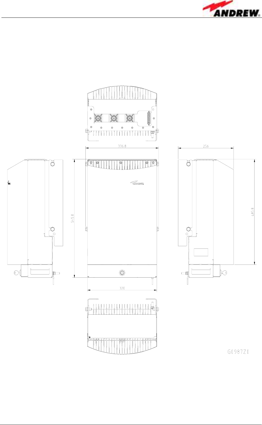
7 Appendix
ID No: 161692 PRELIMINARY Page 91
7 APPENDIX
7.1 ILLUSTRATIONS
7.1.1 Cabinet Drawings
figure 7-1 Cabinet of a Node C
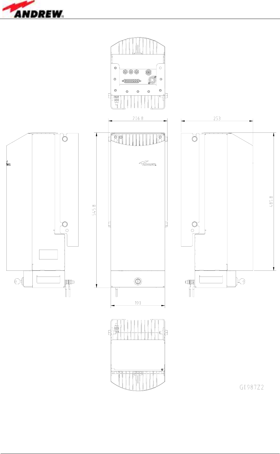
User’s Manual for Node C Network Elements
Page 92 PRELIMINARY M0121A1A_uc.doc
figure 7-2 Cabinet of a Node C Interface Unit
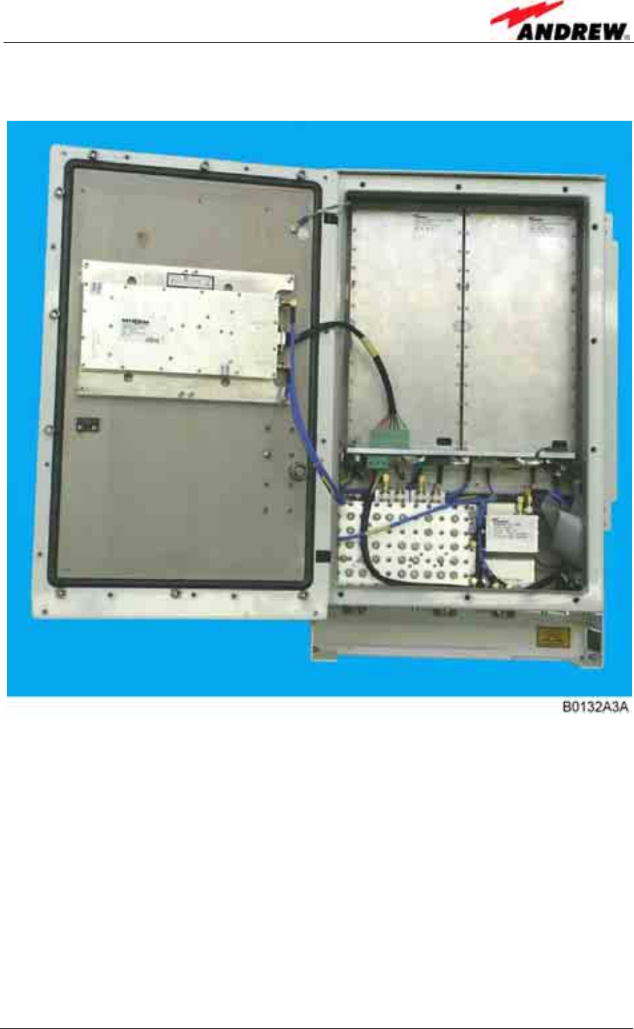
7 Appendix
ID No: 161692 PRELIMINARY Page 93
7.1.2 Layout
figure 7-3 Layout of the Node C 1937, exemplary
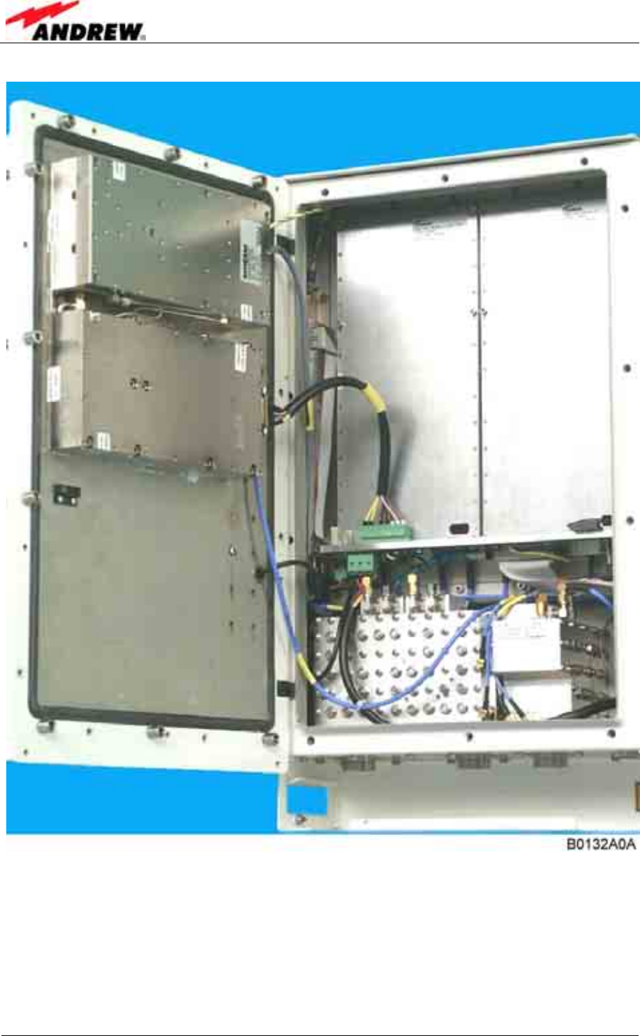
User’s Manual for Node C Network Elements
Page 94 PRELIMINARY M0121A1A_uc.doc
figure 7-4 Layout of the Node C 1943, exemplary
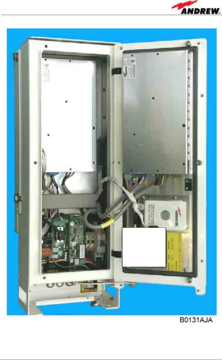
7 Appendix
ID No: 161692 PRELIMINARY Page 95
figure 7-5 Layout of the Interface Unit, exemplary
Position for
optional modem

User’s Manual for Node C Network Elements
Page 96 PRELIMINARY M0121A1A_uc.doc
7.2 SPECIFICATIONS
7.2.1 Electrical Specifications
) Note: For detailed information, refer to the Environmental and Safety
Specifications leaflet of the supplier.
Type Node C 837 Node C 843
Frequency Uplink: 824 – 849 MHz
Downlink: 869 – 894 MHz
CDMA carriers Option 1:
Option 2: 1-8 adjacent (per module) 1.23 MHz carriers
1-2 adjacent (per module) 5 MHz carriers
DL output power 1 CDMA carrier
2 CDMA carriers
4 CDMA carriers
+37.0 dBm
+33.0 dBm
+30.0 dBm
+43.0 dBm
+40.0 dBm
+37.0 dBm
UL composite output power +23 dBm
Output power step size 1 dB
Output power accuracy over all
conditions ±1.5 dB
Min. DL input power for full output
power -56 dBm -60 dBm
Max. input power without damage +10 dBm
Min. antenna isolation for max. gain 73 dB minimum 83 dB minimum
UL noise figure 3.5 dB
Delay Option 1:
Option 2: < 6.5 µs
< 8.0 µs
Maximum gain 93 dB 103 dB
Gain adjust range 43 dB to 93 dB 53 dB to 103 dB
Return loss >15 dB
Uplink diversity Standard
Spectral emission mask -45 dBc @ 750 kHz
-60 dBc @ 1.98 MHz
Out of band gain
(rejection) Option 1:
Option 2: Gain -40 dB in 1.25 MHz
Gain -70 dB in 1.25 MHz
Modulation accuracy ROH > 0.96
Spurious emissions -13 dBm
Far off selectivity (ultimate rejection) 70 dB
Power supply Standard:
Optional: 110 VAC / 40-60 Hz
36-72 VDC
Power consumption 150 W idle
230 W full output
power
300 W idle
500 W full output
power
RF connectors 7/16 DIN female; N female as an option
Ingress protection Cabinet:
Fan: IP66
--- IP66
IP55
Temperature range -33°C to +50°C
All data is subject to change without notice

7 Appendix
ID No: 161692 PRELIMINARY Page 97
Type Node C 1937 Node C 1943
Frequency Uplink: 1850 – 1910 MHz
Downlink: 1930 – 1990 MHz
CDMA carriers Option 1:
Option 2: 1-11 adjacent (per module) 1.23 MHz carriers
1-3 adjacent (per module) 5 MHz carriers
DL output power 1 CDMA carrier
2 CDMA carriers
4 CDMA carriers
+37.0 dBm
+33.0 dBm
+30.0 dBm
+43.0 dBm
+40.0 dBm
+37.0 dBm
UL composite output power +23 dBm
Output power step size 1 dB
Output power accuracy over all
conditions ±1.5 dB
Min. DL input power for full output
power -56 dBm -60 dBm
Max. input power without damage +10 dBm
Min. antenna isolation for max. gain 73 dB minimum 83 dB minimum
UL noise figure 3.5 dB
Delay Option 1:
Option 2: < 6.5 µs
< 8.0 µs
Maximum gain 93 dB 103 dB
Gain adjust range 43 dB to 93 dB 53 dB to 103 dB
Return loss >15 dB
Uplink diversity Standard
Spectral emission mask -45 dBc @ 885 kHz
-55 dBc @ 1.98 MHz
Out of band gain
(rejection) Option 1:
Option 2: Gain -40 dB in 1.25 MHz
Gain -70 dB in 1.25 MHz
Modulation accuracy ROH > 0.96
Spurious emissions -13 dBm
Far off selectivity (ultimate rejection) 70 dB
Power supply Standard:
Optional: 110 VAC / 40-60 Hz
36-72 VDC
Power consumption 150 W idle
230 W full output
power
300 W idle
500 W full output
power
RF connectors 7/16 DIN female; N female as an option
Ingress protection Cabinet:
Fan: IP66
--- IP66
IP55
Temperature Range -33°C to +50°C
All data is subject to change without notice

User’s Manual for Node C Network Elements
Page 98 PRELIMINARY M0121A1A_uc.doc
7.2.2 Mechanical Specifications
Description Node C x37 Node C x43
Height, width, depth 546 x 320 x 260 mm
Weight * 22 kg 25 kg
Cooling Natural convection in the
door and on the back Twin redundant fans in the door
Natural convection on the back
Acoustic noise None 45 dBA typ.
58 dBA typ. @ 25°C ambient
@ 50°C ambient
Description Interface Unit
Height, width, depth 546 x 190 x 260 mm
Weight * 13 kg
Cooling Natural convection in the door and in the back
* in standard configuration
All data is subject to change without notice
7.2.3 Specifications for Optional Equipment
Modem
Service t.b.d.
Service connection t.b.d.
Physical connection RS232; USB (not yet available)
Power consumption 4W average, 10W peak
Connectors Data, power, RF
Battery backup
Battery type NiCd
Battery capacity 1200mAh
Nominal output voltage 8.4 V
Backup time >15minutes (25W load @ 25°C)
Charge time 4.5 hours maximum
Maintenance discharge time 2 hours
Major features Battery charge and discharge control,
active HID, battery voltage measurement
All data is subject to change without notice

7 Appendix
ID No: 161692 PRELIMINARY Page 99
7.3 PARTSLISTS
The following lists contain a list of all FRUs that are available for the Node C and
Interface Unit. The Node C configuration is available in the configuration list1, which
is delivered with the unit.
Please observe that in the following lists only the components marked * may be
replaced on site. If the replacement of any other component in this list is required,
please contact customer service for assistance.
1 To be replaced by an electronic door label that will be accessible via software.
7.3.1 Interface Unit
Interface Unit 159557
Battery Backup Kit 159548 *
Cabinet Combining Kit 161240
Charge Control Board 160098
Connecting- and Sparepart Kit 160069
Cover 160736
Distribution and Alarm Board 160415
Drawer 160734
Modem t.b.d.
Memory board 1627.2 I2C-ADD 51 159809
Modem Kit USA/BBU L-Cab. 161489 *
NiCd-Akku 8,4V/1200mAh, N-1200SCK,70°C 160188 *
Power Supply In:115Vac±15%, 47-65Hz 159126 *
Power Supply In:230Vac±15%, 47-65Hz 159514 *
Wall Mounting Kit 160068
The manufacturer reserves the right to replace the parts listed above by equivalent
substitutes!

User’s Manual for Node C Network Elements
Page 100 PRELIMINARY M0121A1A_uc.doc
7.3.2 Node C
NodeC Type 837 843 1937 1943
Description ID No.
Node C 160546 160545 160543 160544
Adapter 7/16 male -N female 112425
Cover 160735
BW 15 MHz 869-894MHz 160548 ---
Dig.Chan.
Mod. DL BW 15 MHz 1930-1990MHz --- 160550
BW 15 MHz 824-849MHz 160547 ---
Dig.Chan.
Mod. UL BW 15 MHz 1850-1910MHz --- 160549
Drawer 160733
Duplexer DL / LNA:824-849/869-894MHz 161464 ---
Duplexer DL / LNA:1850-1910/1930-1990MHz --- 161462
Duplexer UL / LNA:824-849/869-894MHz 161463 ---
Duplexer UL / LNA:1850-1910/1930-1990MHz --- 161461
Fan Unit 1 --- 159547 --- 159547
Fin.Amp. 26-28V, 47dB, 1930-1990MHz --- 160254
Fin.Amp.4W M,12V,33dB 824-849MHz 160417 ---
Fin.Amp.4W M,12V,33dB 1850-1910MHz --- 160416
Fin.Amp.30W,26-28V,36dB 1930-1990,Feedf. --- 160255 ---
Fin.Amp. 82W, MLPA 28V/46dB/869-894MHz --- 158789 ---
Fin.Amp. 82W, MLPA 28V/36dB/869-894MHz 161235 ---
Memory board 1627.2 I2C-ADD 50 159810
Pole mounting 160979
Pole mounting Kit (2 Systems) 161604
Pole mounting Kit Back to Back (1System) 161605
RF/DC Distribution Unit 159539
Wall Mounting Kit 160068
1 The fan unit can only be replaced as a whole. Do not replace an individual fan.
The manufacturer reserves the right to replace the parts listed above by equivalent
substitutes!

8 Index
ID No: 161692 PRELIMINARY Page 101
8 INDEX
A
Abbreviations............................................7
Address of Mikom.....................................9
Alarmforwarding .....................................73
Alarms
External .....................................................74
Management .............................................65
Setting of Severity Level ...........................65
Setting of Threshold..................................65
Amplifier
Feed-Forward............................................80
Final...........................................................80
Antenna Tuning......................................62
B
Battery Backup.......................................85
Block Diagram
DC .............................................................69
RF..............................................................70
C
Cabinet Drawing
Interface Unit.............................................92
Node C ......................................................91
Commissioning.......................................25
Communication Mode Parameters.........84
Connections
Antenna.....................................................23
Cable Bridge..............................................23
Login Devices............................................26
Login Procedures......................................26
Optional Equipment...................................24
Power ........................................................22
Control Board .........................................82
D
DCM Module ..........................................79
Design ....................................................70
Digital ICE ..............................................72
Distribution & Alarm Board.....................82
Diversity............................................77, 79
Duplexer.................................................76
E
External Alarms......................................74
Naming......................................................65
F
Feed-Forward Amplifier..........................80
Filters
High Rejection Option............................... 86
Standard Feature...................................... 72
Final Amplifier.........................................80
G
Grounding...............................................21
H
Health and Safety Warnings.....................8
High Rejection Filter...............................86
I
Installation
Direct connection on Win2000 ................. 48
Direct Connection on WinXP.................... 28
Electrical ................................................... 20
Mechanical ............................................... 13
Modem Connection on WinXP ................. 38
USB Driver................................................ 27
International Contact Addresses ............10
L
Layout
Interface Unit ............................................ 95
Node C 1937 ............................................ 93
Node C 1943 ............................................ 94
Total.......................................................... 76
LNA ........................................................76
Low-Noise Amplifier ...............................76
M
Menus
Alarm Management .................................. 65
Connectivity and Upload........................... 63
Setup Wizard............................................ 61
Technician Setup...................................... 64
Modem
General..................................................... 83
Initstrings .................................................. 84
Wireless.................................................... 84
Mounting
Brackets.............................................. 16, 18
Connection Option.................................... 16
General..................................................... 13
Pole........................................................... 17
Wall........................................................... 14

User’s Manual for Node C Network Elements
Page 102 PRELIMINARY M0121A1A_uc.doc
O
Optional Equipment................................83
P
Partslist
Interface Unit.............................................99
Node C ....................................................100
Power Supply .........................................83
Preamble..................................................9
PSU Redundancy...................................86
R
Remote Control ......................................26
Remote Login.........................................26
Replacement of
Battery Backup..........................................90
Modem ......................................................89
Power Supply ............................................88
RF Path ..................................................71
RF/DC Distribution Unit..........................78
RSSI.......................................................73
S
SMS Alarmforwarding ............................73
Software Setup.................................26, 66
Specifications
Electrical (Node C 19xx)........................... 97
Electrical (Node C 8xx)............................. 96
Mechanical ............................................... 98
Optional Equipment.................................. 98
Summary Alarm......................................75
T
Troubleshooting......................................66
U
USB
Adapter ..................................................... 26
Driver ........................................................ 27
V
VSWR.....................................................73
W
Web Page
Access ...................................................... 60
Main Menus.............................................. 61