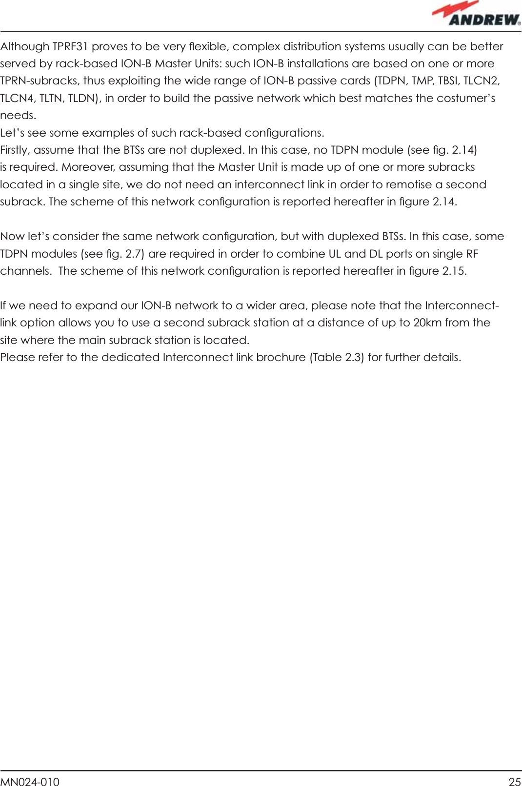
Andrew Wireless Innovations Group TFAHUS5 TFAH-US5B HIGH POWER REMOTE UNIT User Manual
Andrew Wireless Innovations Group TFAH-US5B HIGH POWER REMOTE UNIT
UserManual.wiki
>
Andrew Wireless Innovations Group
>
TFAHUS5 User Manual
USERS MANUAL
Navigation menu
Upload a User Manual
Namespaces
Wiki Guide
HTML
PDF
Info
Views
User Manual
Discussion / Help
Navigation


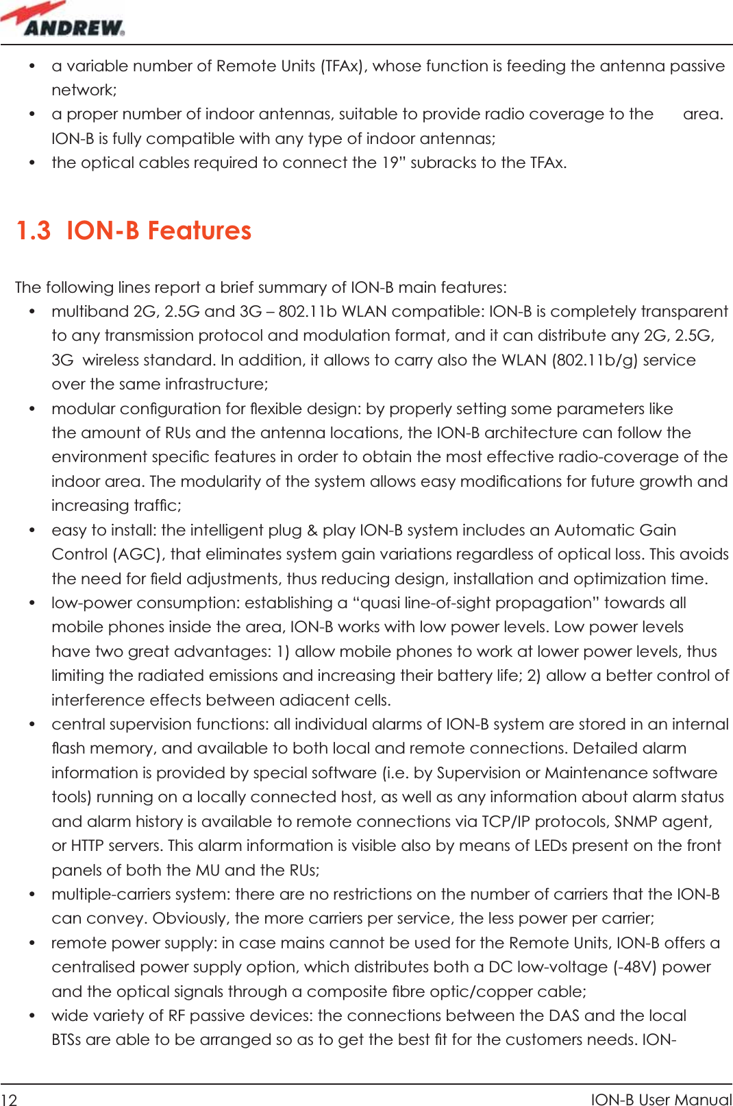


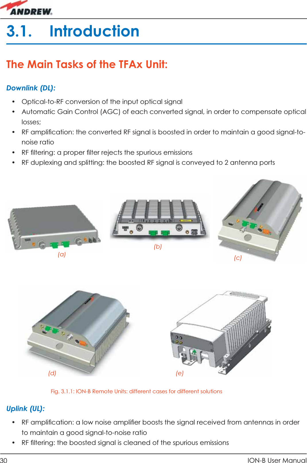

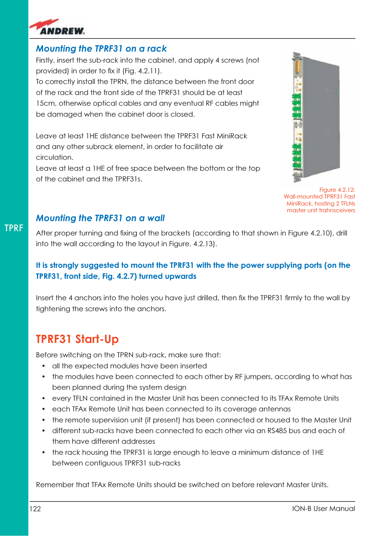
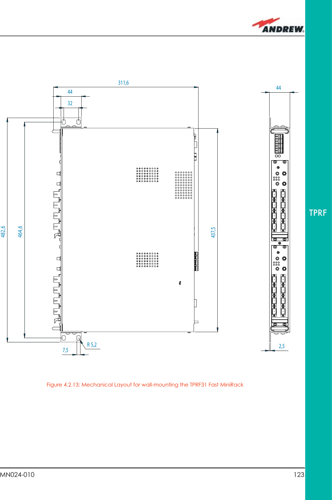
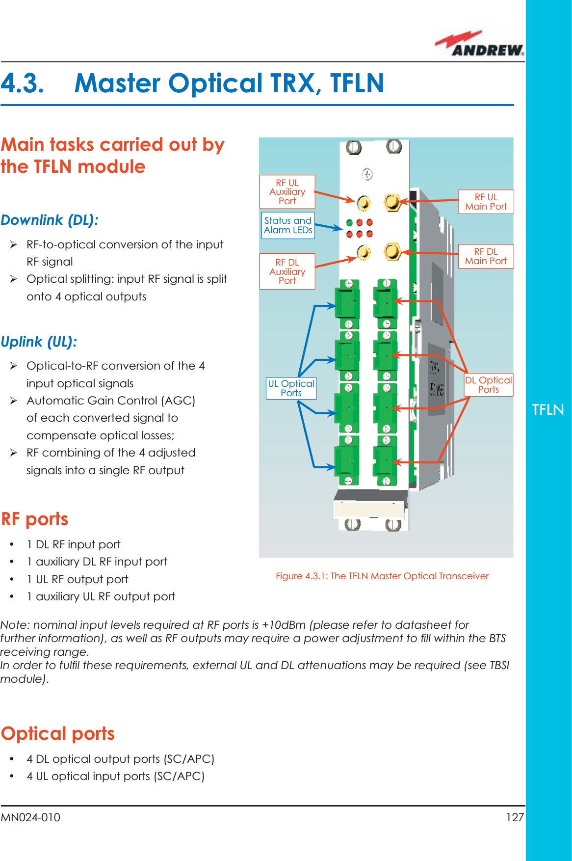
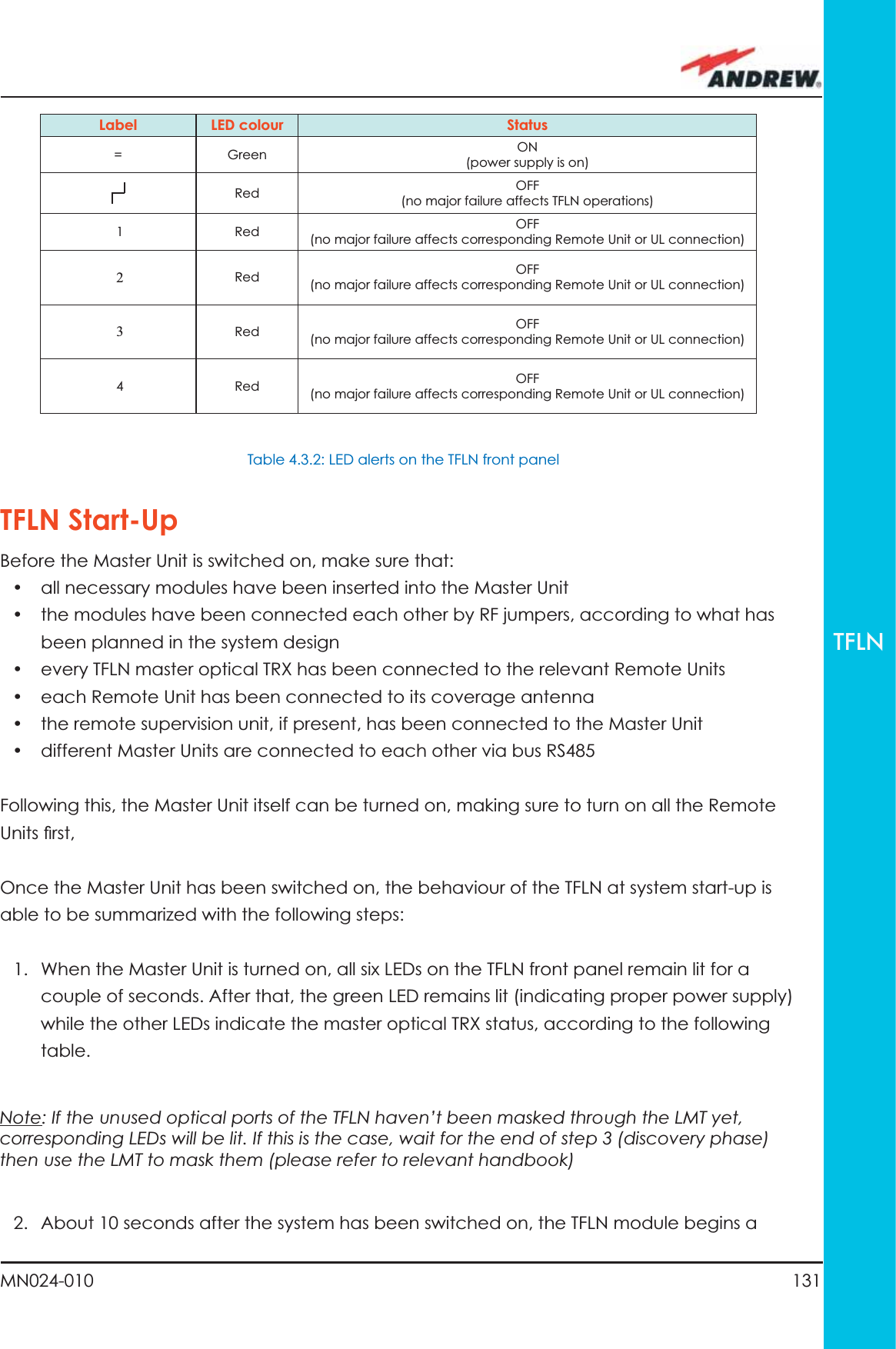
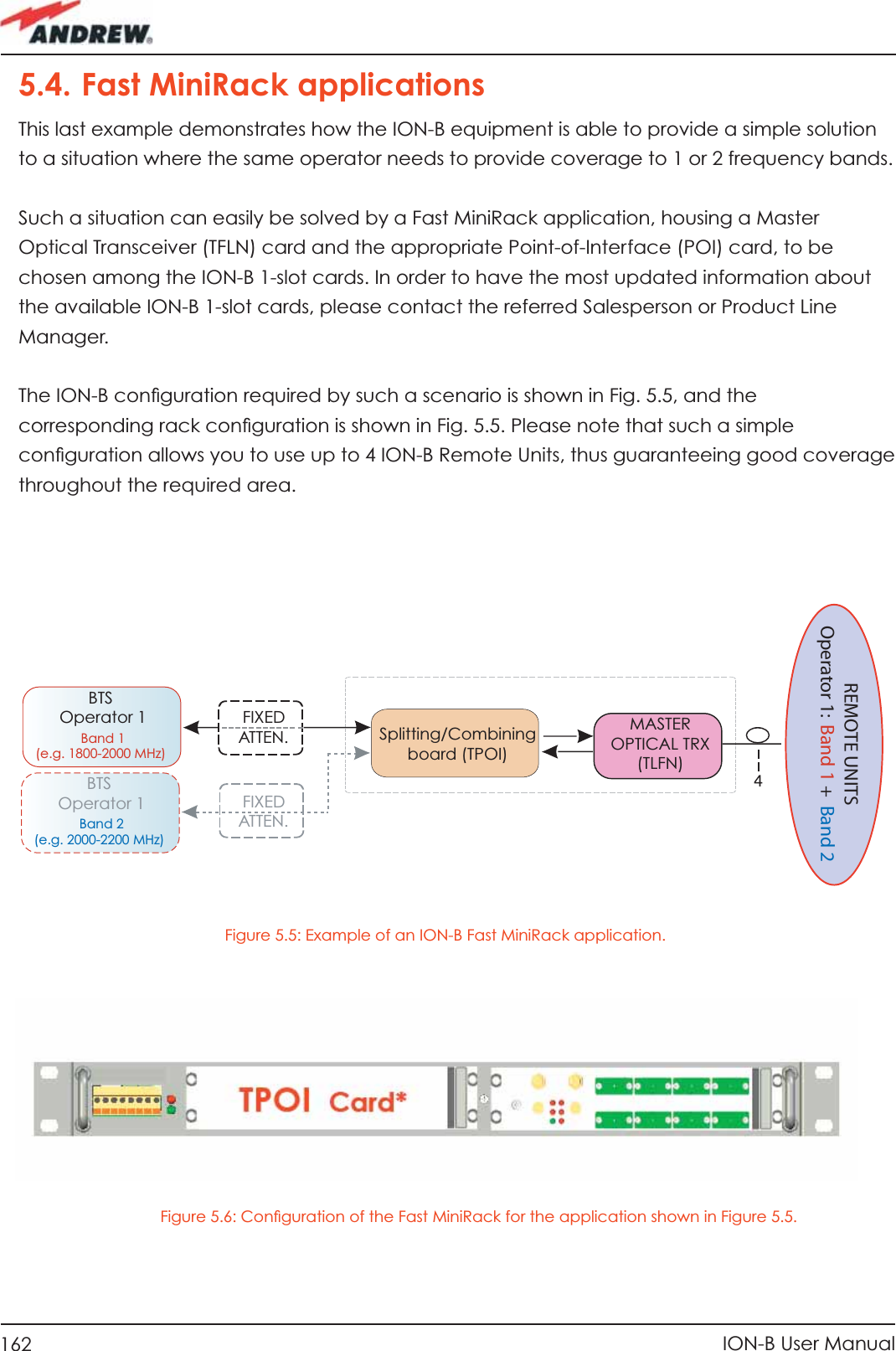
![60 ION-B User ManualTFAMCase BstartendGo to the TFLN sideThe troubleshooting procedure has not identi-fied the problem. Use the supervision system or contact assistanceDisconnect the optical SC-APC connector from the remote unit DL port.Is this dry-contact electrically closed?YesYesYesNoNoNoExternal equipment connected to this dry contact port should be faulty. Test it. Disconnect the optical fiber and clean it at both ends. Is ADL >4dB?Is any dry contact connected to some external equipment?Is the red LEDupon the TFAx still ON??Are SC-APC connectors properly installed at both fiber ends?Fix better the SC-APC connectors.Clean the optical SC-APC ports on both the TFLN and the remote unit. Measure the output power at the corre-sponding fiber ends.Disconnect the optical SC-APC connectors from the TFLN DL portsCalculate the fiber DL attenuation:ADL[dB]=input power - output powerMeasure the input power coming out of the TFLN DL portFiber optic cable has some problems. Please replace itRearrange the optical path to avoid sharp bends. If necessary, replace the optical cable with a longer one Is the red LEDupon the TFAx still ON??NoYesYesNoNoYesFigure 3.3.14 (b): Flow-chart describing the quick troubleshooting procedure of a TFAx Case B](https://usermanual.wiki/Andrew-Wireless-Innovations-Group/TFAHUS5/User-Guide-898846-Page-60.png)
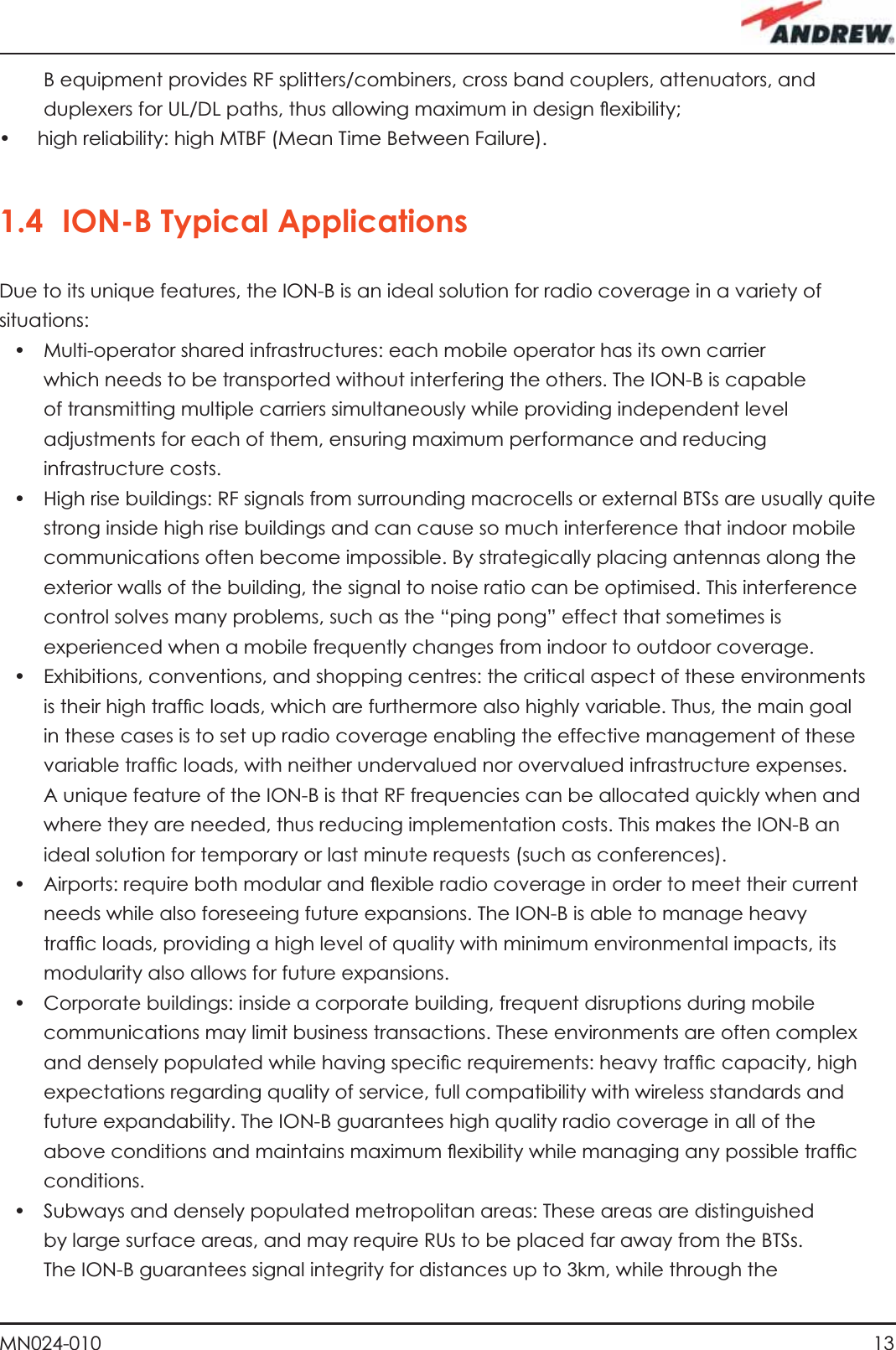
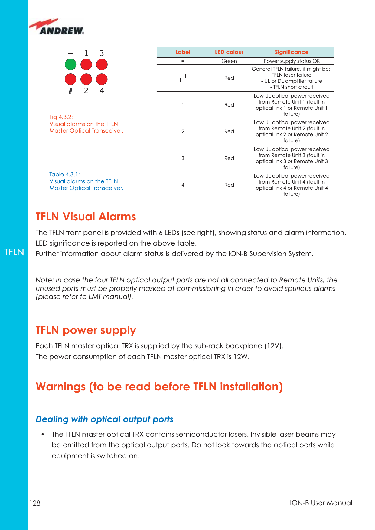
![61MN024-010TFAMCase BstartendGo to the TFLN sideThe troubleshooting procedure has not identi-fied the problem. Use the supervision system or contact assistanceDisconnect the optical SC-APC connector from the remote unit DL port.Is this dry-contact electrically closed?YesYesYesNoNoNoExternal equipment connected to this dry contact port should be faulty. Test it. Disconnect the optical fiber and clean it at both ends. Is ADL >4dB?Is any dry contact connected to some external equipment?Is the red LEDupon the TFAx still ON??Are SC-APC connectors properly installed at both fiber ends?Fix better the SC-APC connectors.Clean the optical SC-APC ports on both the TFLN and the remote unit. Measure the output power at the corre-sponding fiber ends.Disconnect the optical SC-APC connectors from the TFLN DL portsCalculate the fiber DL attenuation:ADL[dB]=input power - output powerMeasure the input power coming out of the TFLN DL portFiber optic cable has some problems. Please replace itRearrange the optical path to avoid sharp bends. If necessary, replace the optical cable with a longer one Is the red LEDupon the TFAx still ON??NoYesYesNoNoYesFigure 3.3.14 (c): Flow-chart describing the quick troubleshooting procedure of a TFAx Case B](https://usermanual.wiki/Andrew-Wireless-Innovations-Group/TFAHUS5/User-Guide-898846-Page-61.png)
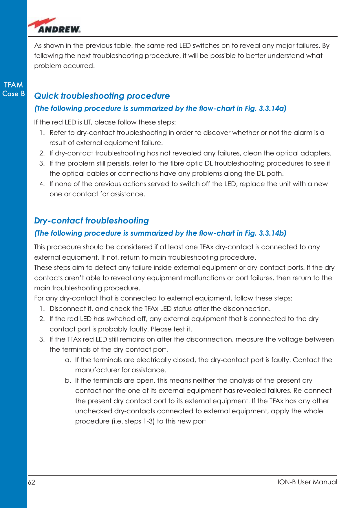
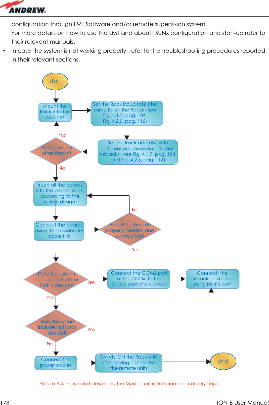
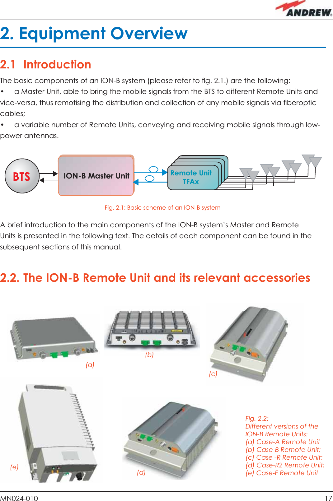
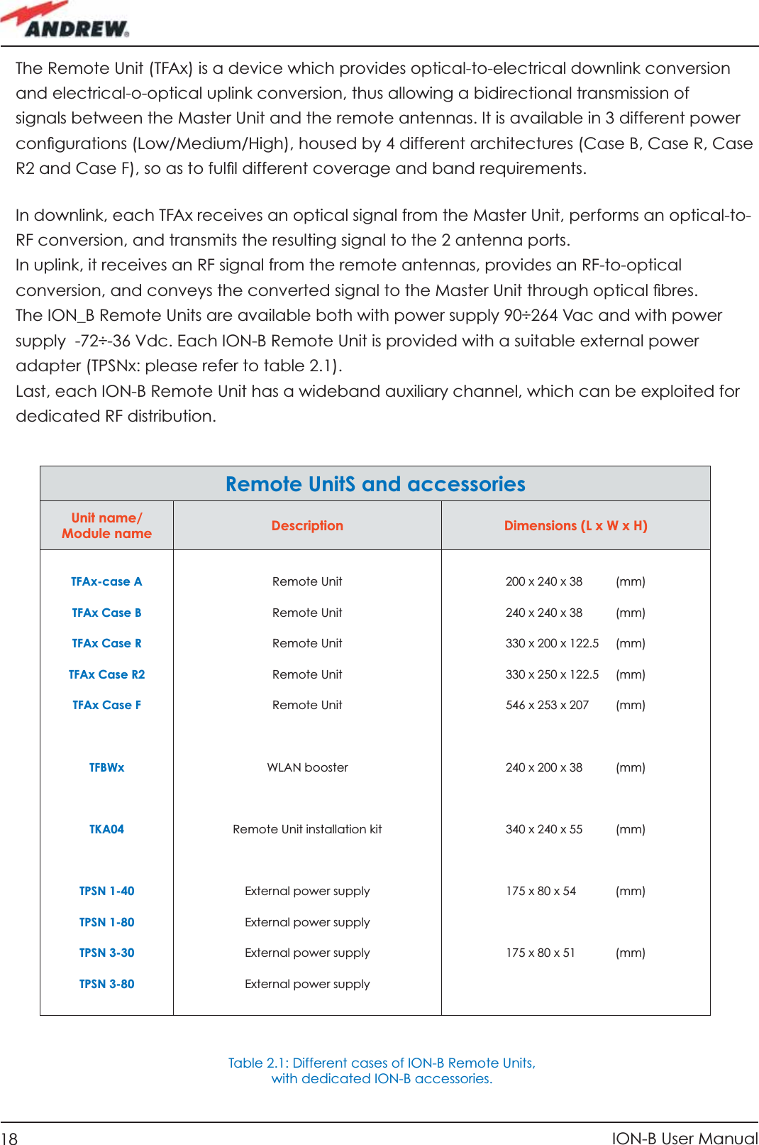
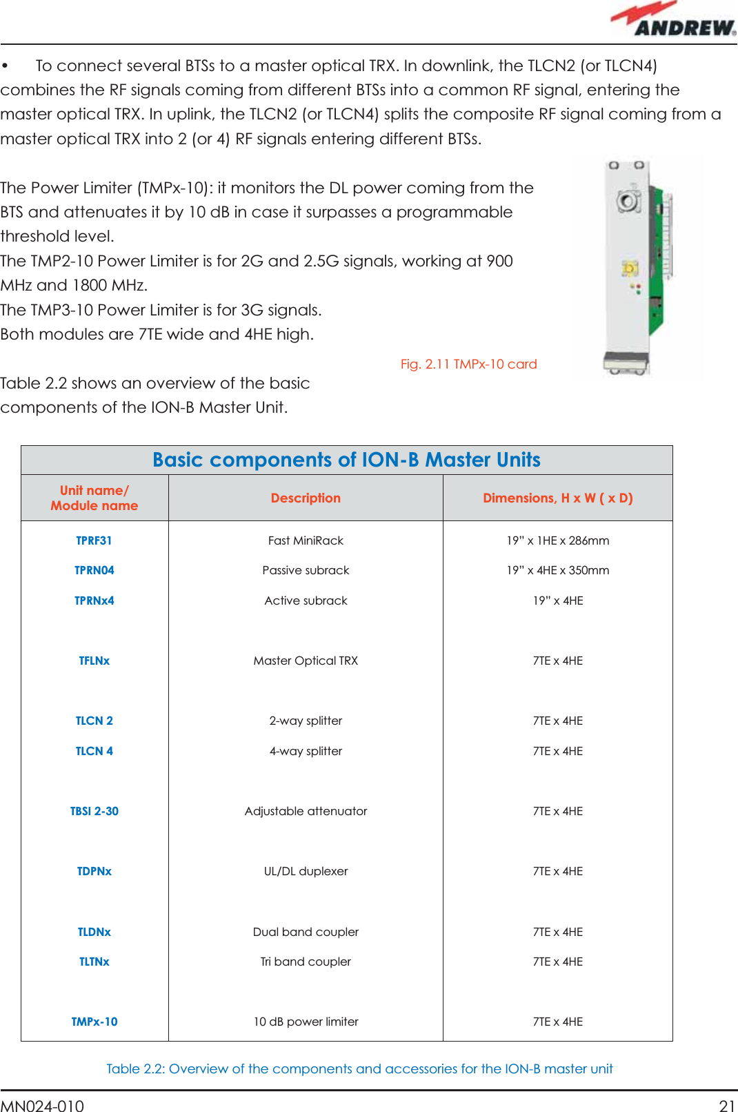
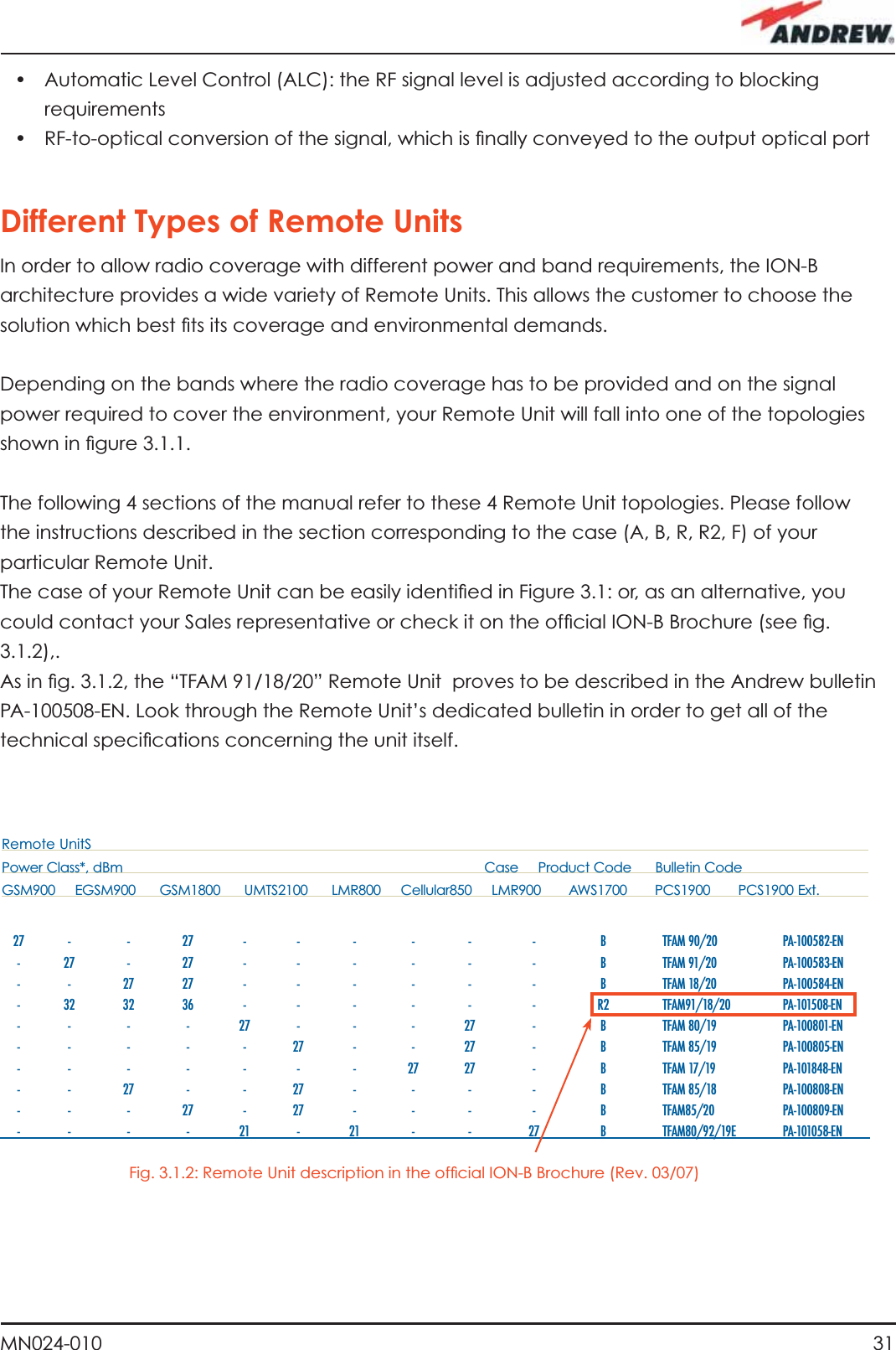
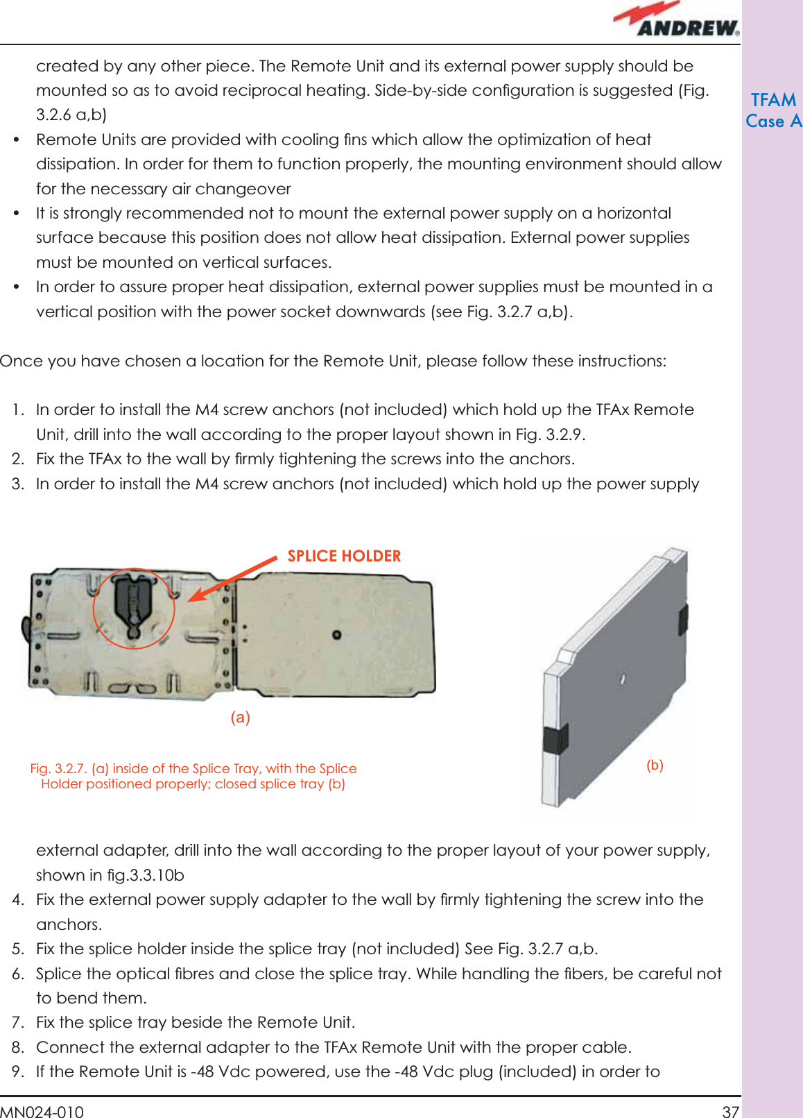
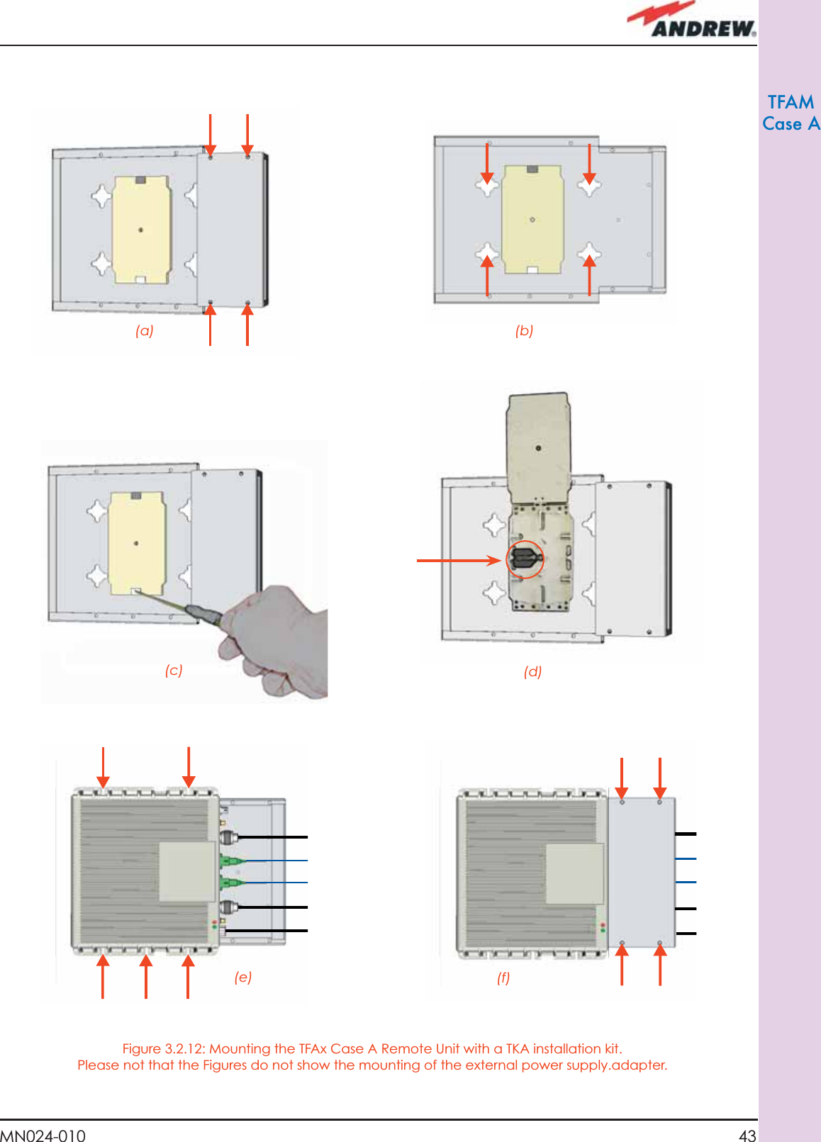
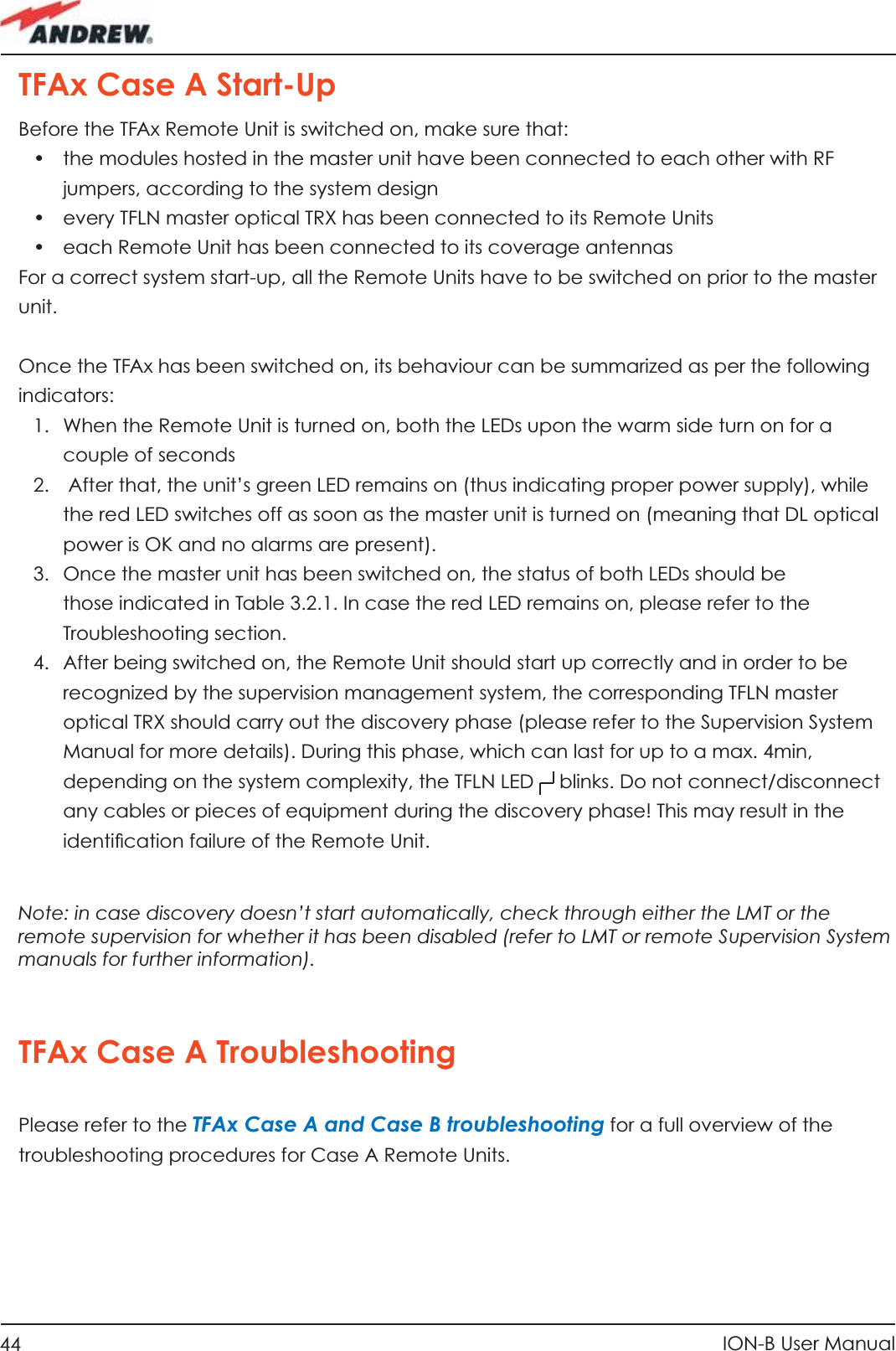
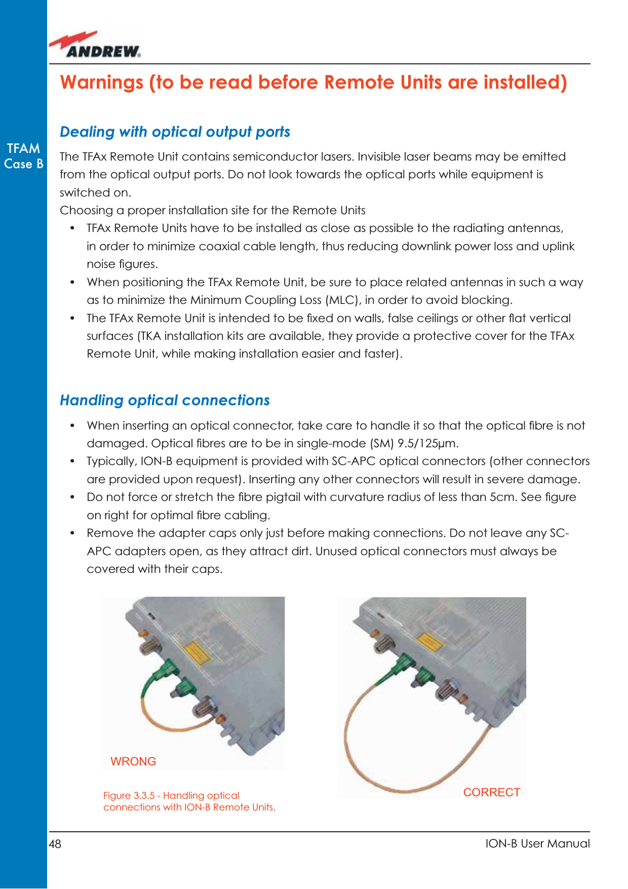
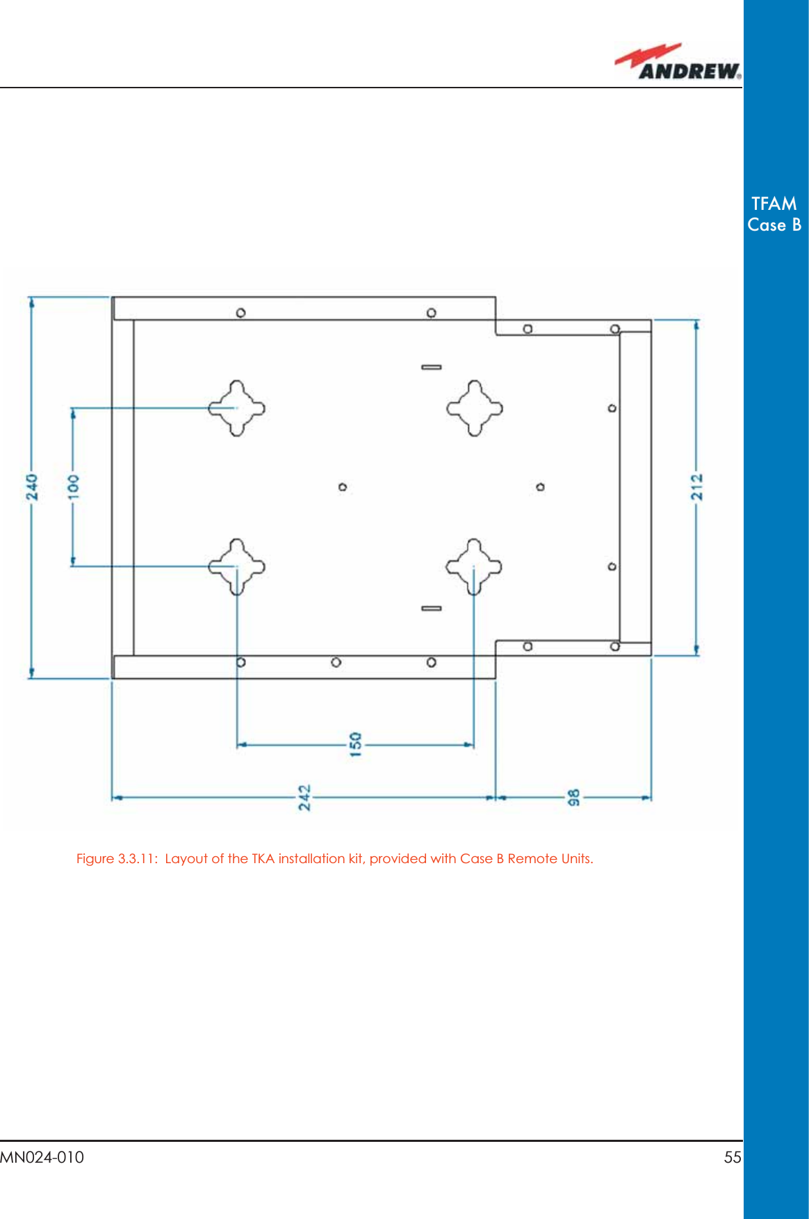
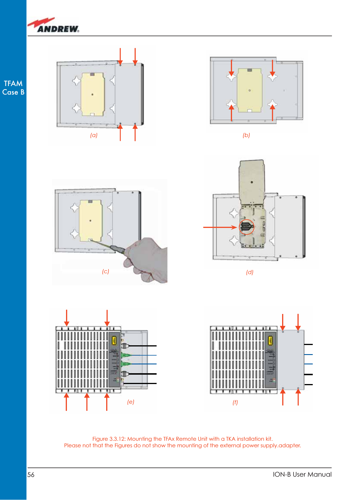
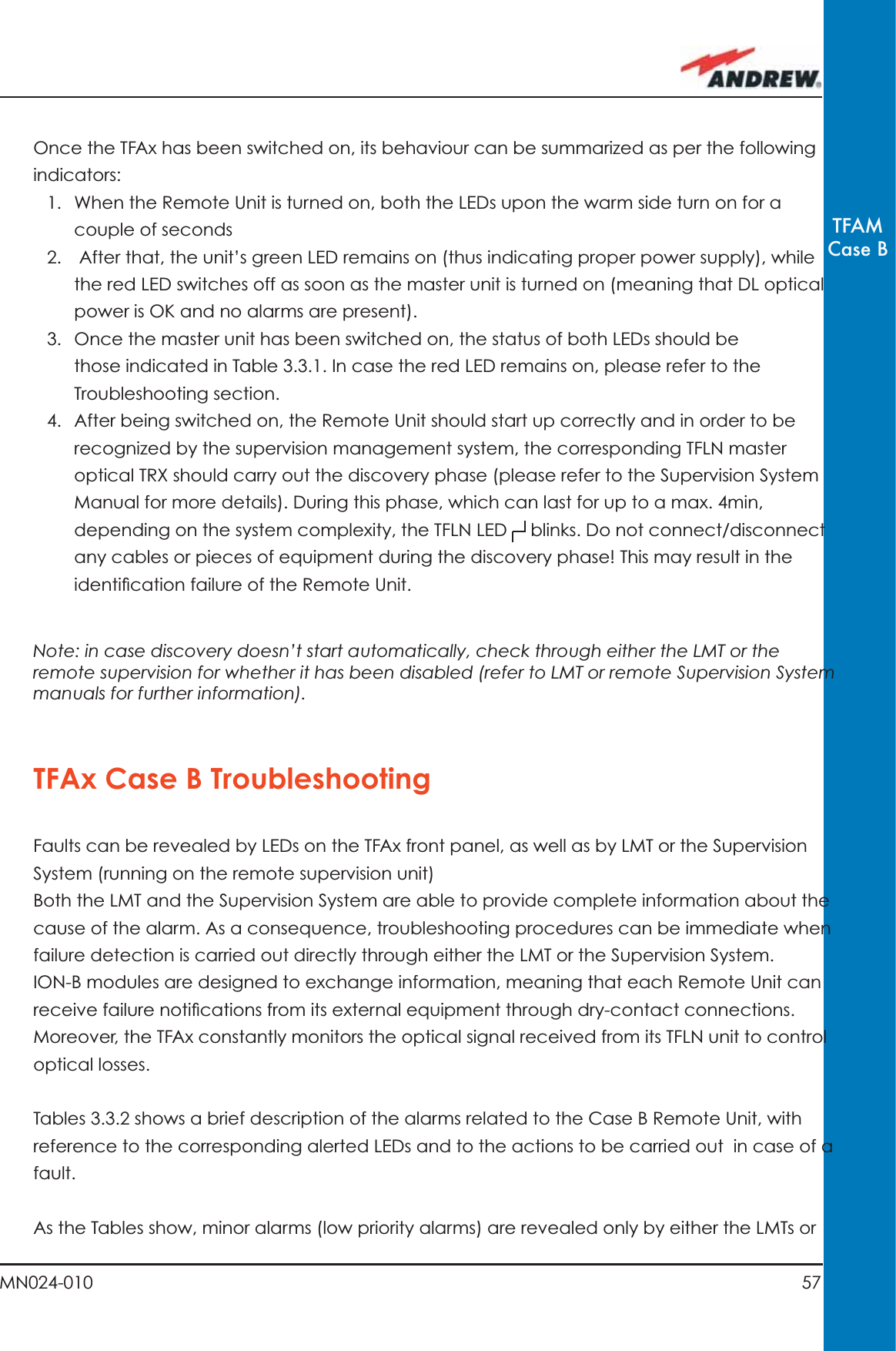
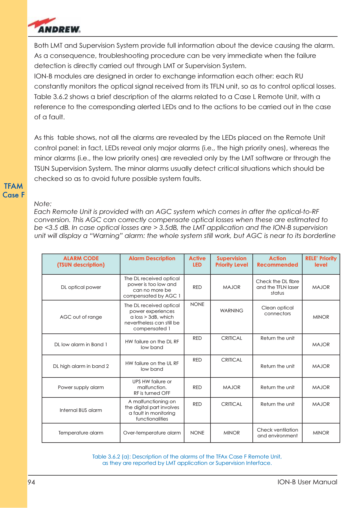
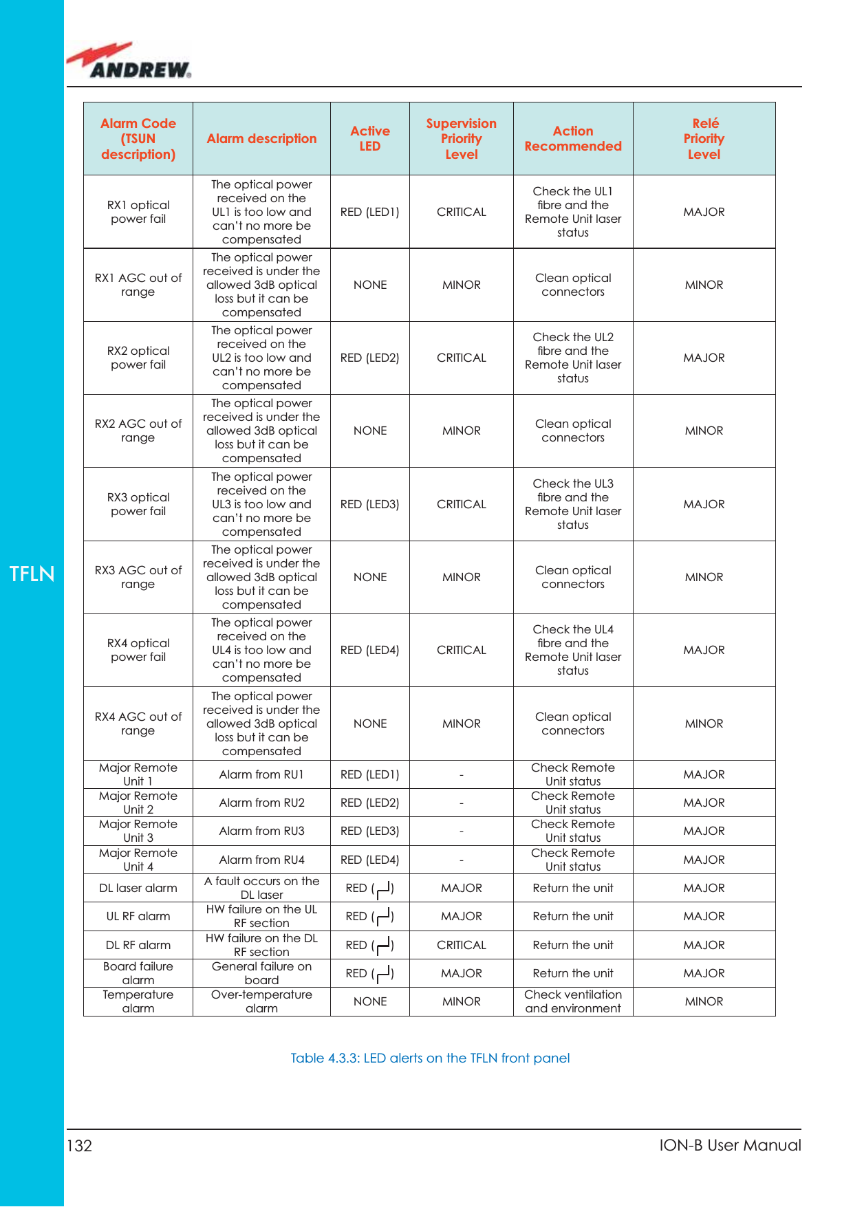
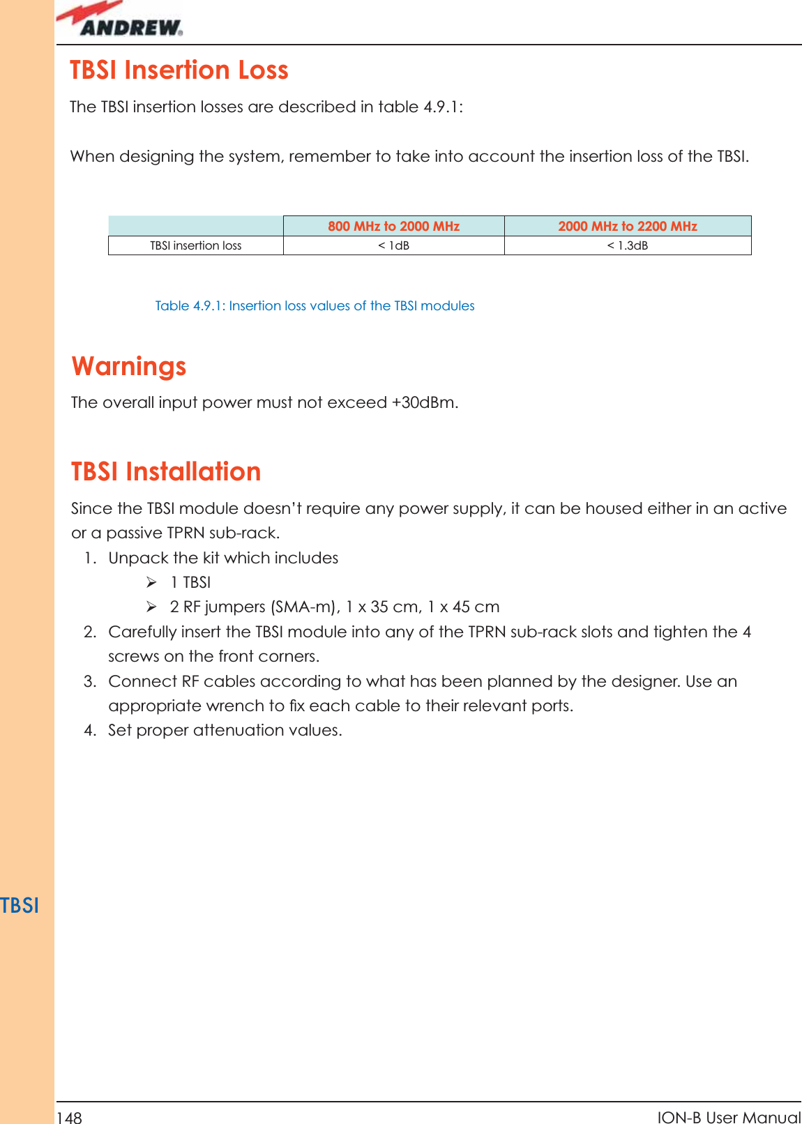
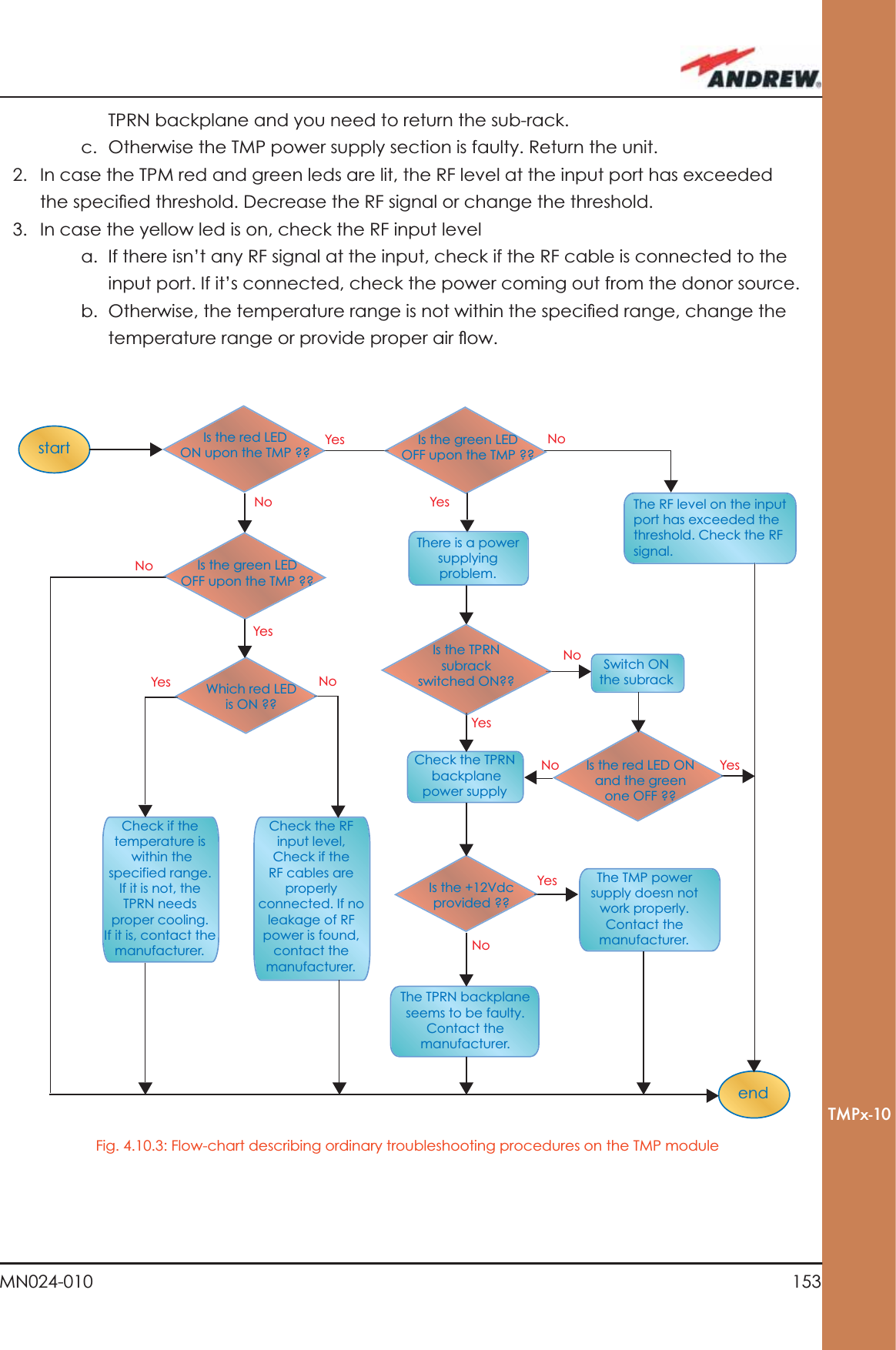
![63MN024-010TFAMCase BFibre optic DL troubleshooting(The following procedure is summarized by the fl ow-chart in Fig. 3.3.14c)1. Check to see if there are any points in which fi bres are experiencing a short radius of curvature. In these cases, rearrange the optical path in order to avoid sharp bends (if necessary, replace the optical cable with a longer one). If the TFLN red LED switches off, troubleshooting has been successfully carried out. Otherwise, follow the next steps.2. Check to see if SC-APC connectors are properly installed at both fi bre ends. In case they are not, replug the SC-SPC connectors to adapters. If the TFLN red LED switches off, troubleshooting has been successful. Otherwise, follow the next steps.3. Disconnect the optical fi bre and clean it at both ends, then clean the SC-APC ports on both the TFLN and the Remote Unit. Re-connect the fi bre to relevant ports after cleaning. If it hasn’t made the TFLN red LED switch off, follow the next steps.4. Disconnect the optical SC-APC connector from the Remote Unit’s DL port, and measure the output power POUT(DL) at the corresponding fi bre end. Then, go to the TFLN side, disconnect the optical SC-APC connector from the TFLN DL port and measure the input power PIN(DL) coming out of the TFLN DL port. Calculate the DL fi bre attenuation ADL as ADL [dB] = PIN(DL) – POUT(DL) a. If ADL > 4dB, then there are problems with the fi bre optic cable. Replace it with a new one.b. If ADL < 4dB, the troubleshooting procedure has not identifi ed the problem. Refer to the Supervision System or contact assistance.](https://usermanual.wiki/Andrew-Wireless-Innovations-Group/TFAHUS5/User-Guide-898846-Page-63.png)

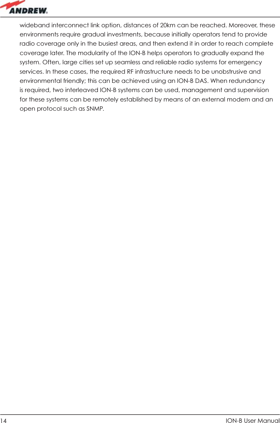
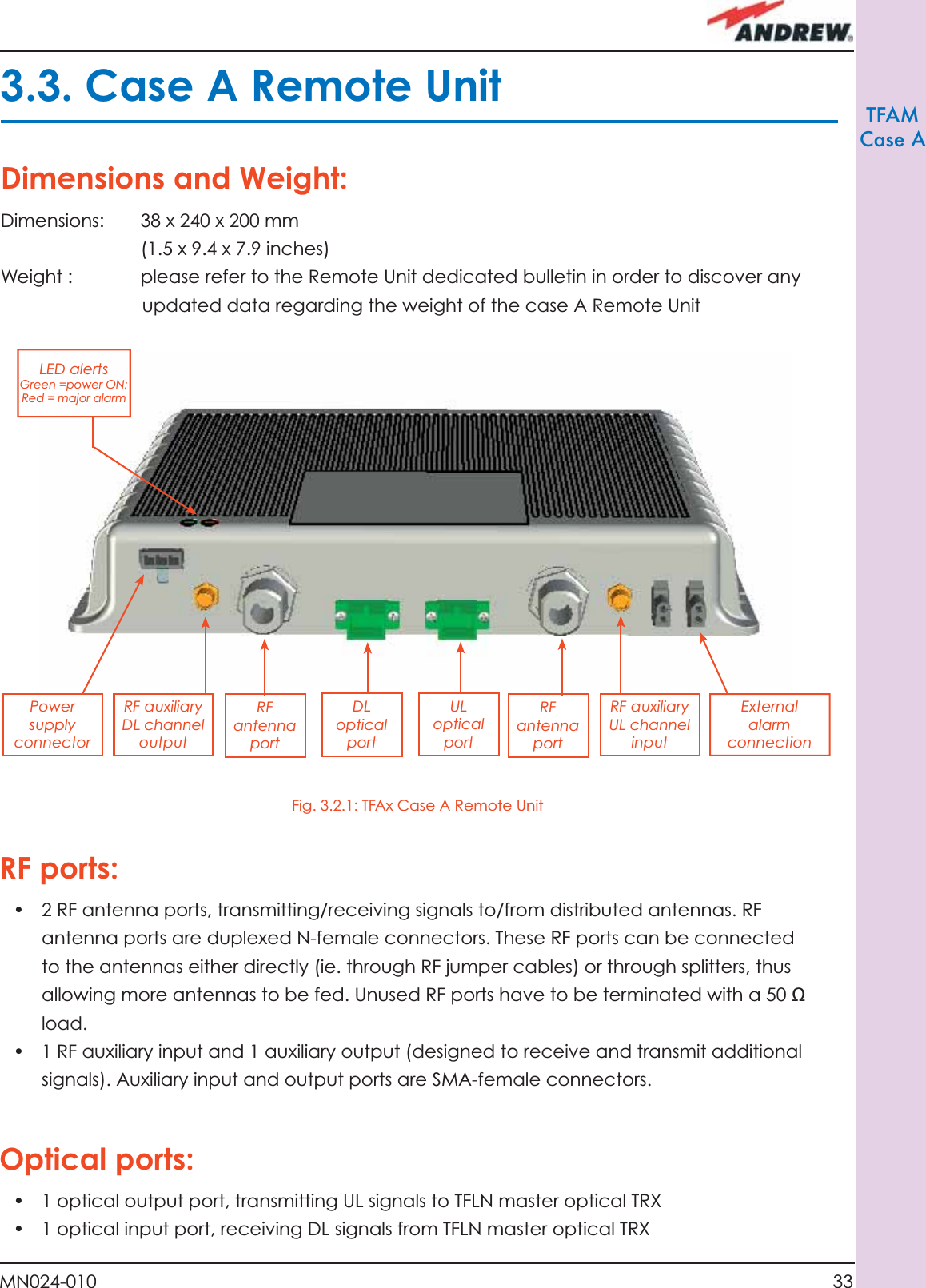
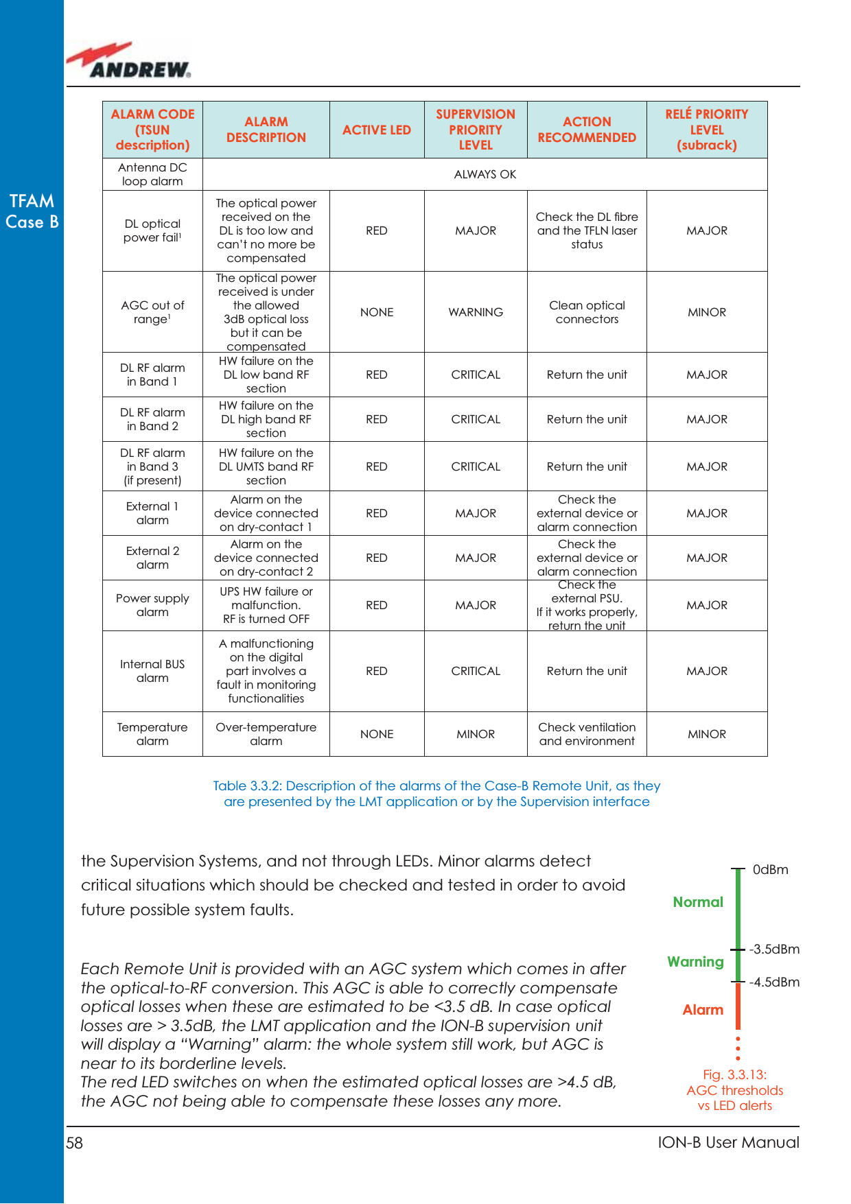
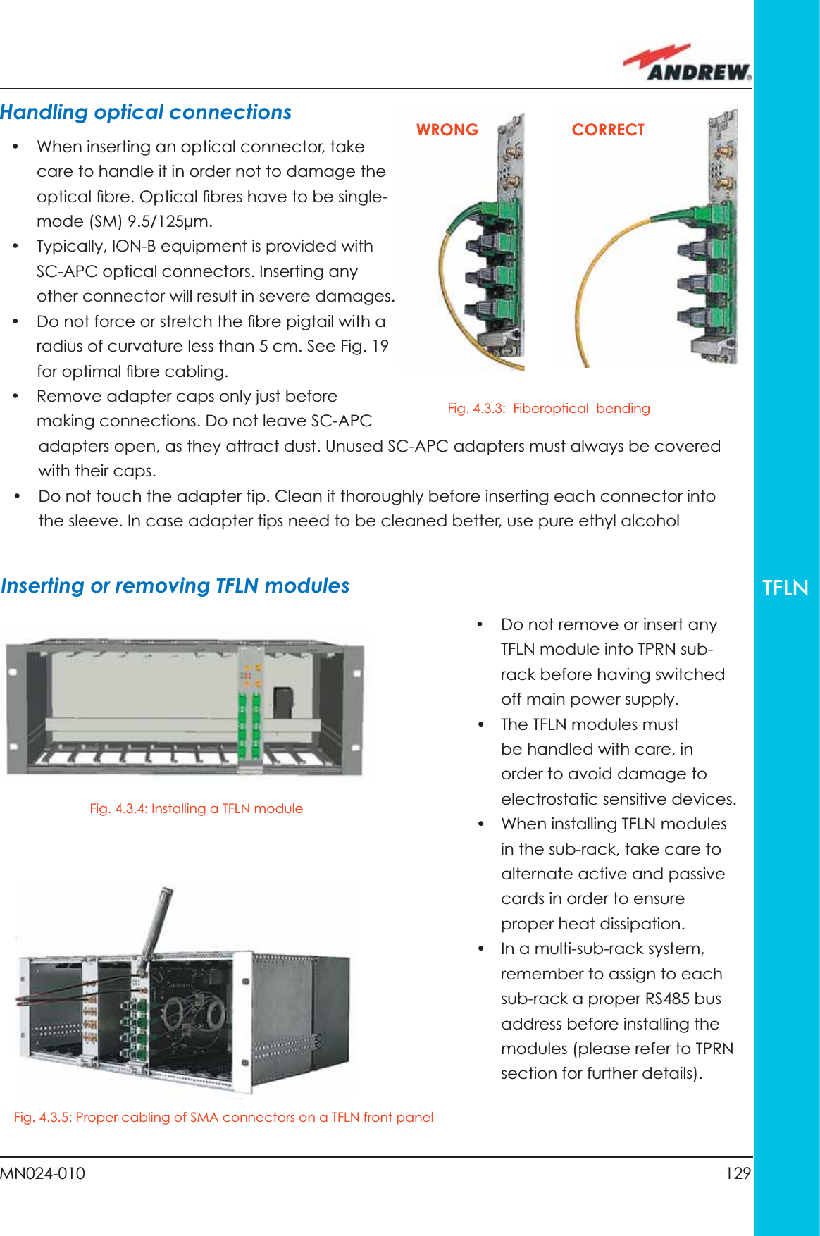
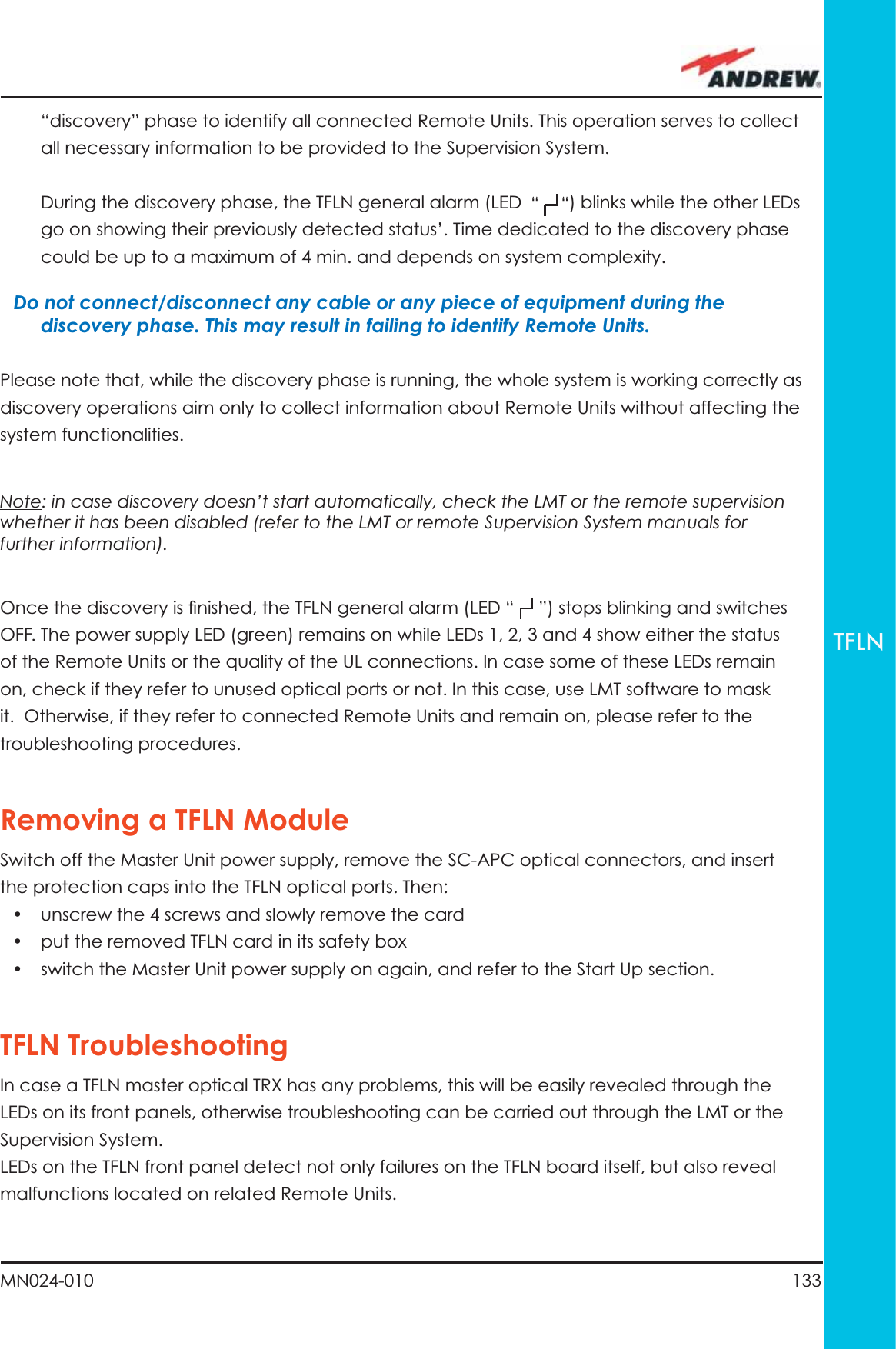
![83MN024-010TFAMCase R2startendGo to the TFLN sideThe troubleshooting procedure has not identi-fied the problem. Use the supervision system or contact assistanceDisconnect the optical SC-APC connector from the remote unit DL port.Is this dry-contact electrically closed?YesYesYesNoNoNoExternal equipment connected to this dry contact port should be faulty. Test it. Disconnect the optical fiber and clean it at both ends. Is ADL >4dB?Is any dry contact connected to some external equipment?Is the red LEDupon the TFAx still ON??Are SC-APC connectors properly installed at both fiber ends?Fix better the SC-APC connectors.Clean the optical SC-APC ports on both the TFLN and the remote unit. Measure the output power at the corre-sponding fiber ends.Disconnect the optical SC-APC connectors from the TFLN DL portsCalculate the fiber DL attenuation:ADL[dB]=input power - output powerMeasure the input power coming out of the TFLN DL portFiber optic cable has some problems. Please replace itRearrange the optical path to avoid sharp bends. If necessary, replace the optical cable with a longer one Is the red LEDupon the TFAx still ON??NoYesYesNoNoYesFigure 3.5.7 (b): Flow-chart describing the external alarm troubleshooting on TFAx Case R2](https://usermanual.wiki/Andrew-Wireless-Innovations-Group/TFAHUS5/User-Guide-898846-Page-83.png)
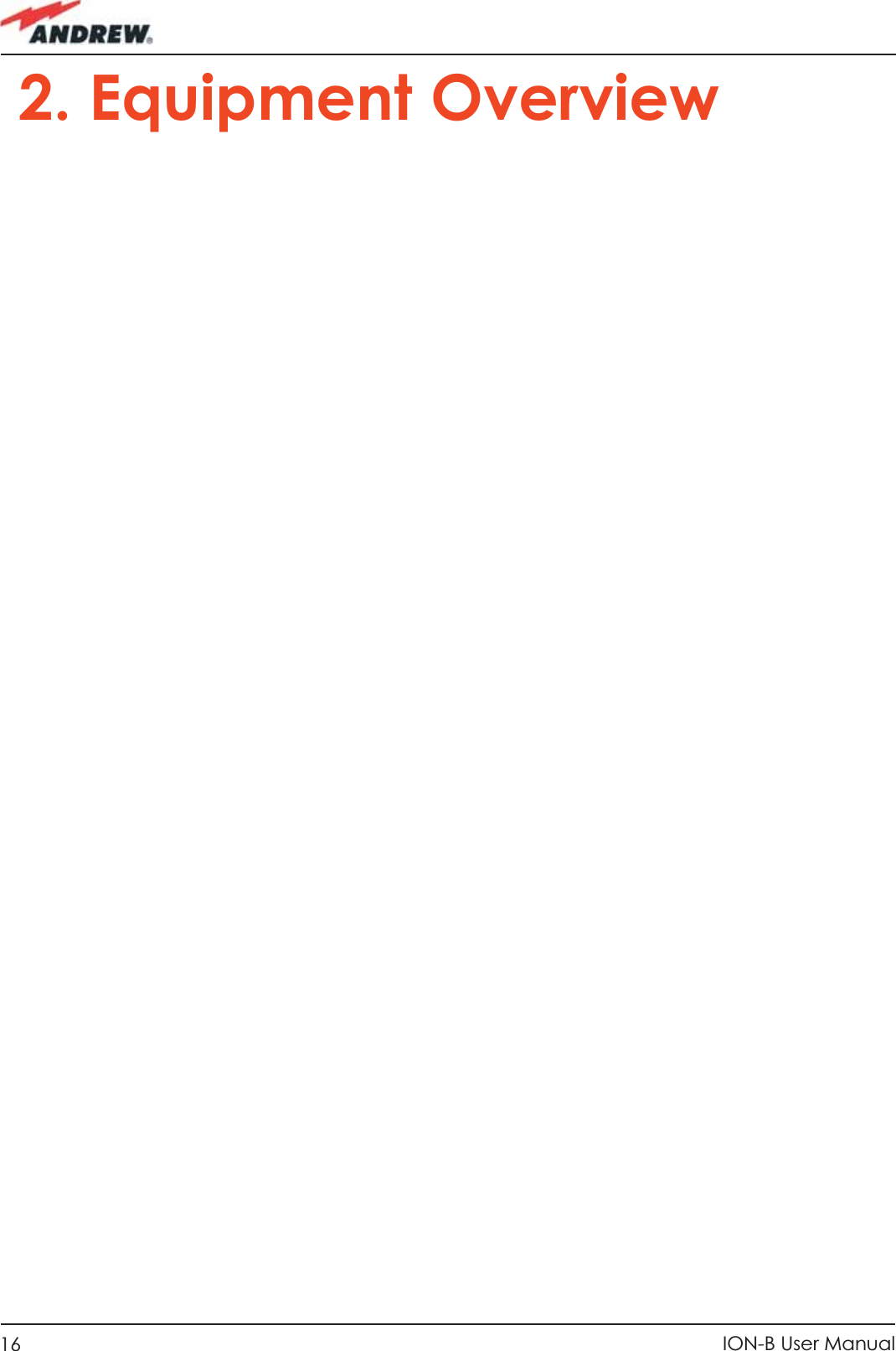
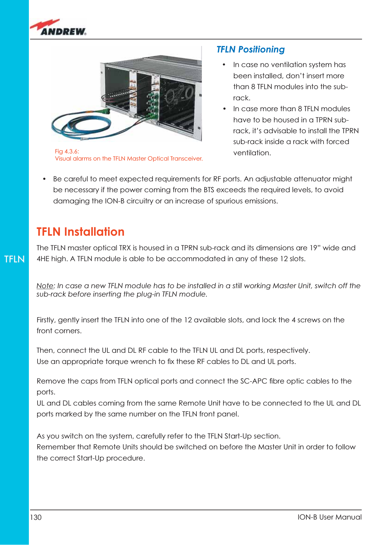
![84 ION-B User ManualTFAMCase R2startendGo to the TFLN sideThe troubleshooting procedure has not identi-fied the problem. Use the supervision system or contact assistanceDisconnect the optical SC-APC connector from the remote unit DL port.Is this dry-contact electrically closed?YesYesYesNoNoNoExternal equipment connected to this dry contact port should be faulty. Test it. Disconnect the optical fiber and clean it at both ends. Is ADL >4dB?Is any dry contact connected to some external equipment?Is the red LEDupon the TFAx still ON??Are SC-APC connectors properly installed at both fiber ends?Fix better the SC-APC connectors.Clean the optical SC-APC ports on both the TFLN and the remote unit. Measure the output power at the corre-sponding fiber ends.Disconnect the optical SC-APC connectors from the TFLN DL portsCalculate the fiber DL attenuation:ADL[dB]=input power - output powerMeasure the input power coming out of the TFLN DL portFiber optic cable has some problems. Please replace itRearrange the optical path to avoid sharp bends. If necessary, replace the optical cable with a longer one Is the red LEDupon the TFAx still ON??NoYesYesNoNoYesFigure 3.5.7 (c): Flow-chart describing the fi beroptiic troubleshooting](https://usermanual.wiki/Andrew-Wireless-Innovations-Group/TFAHUS5/User-Guide-898846-Page-84.png)
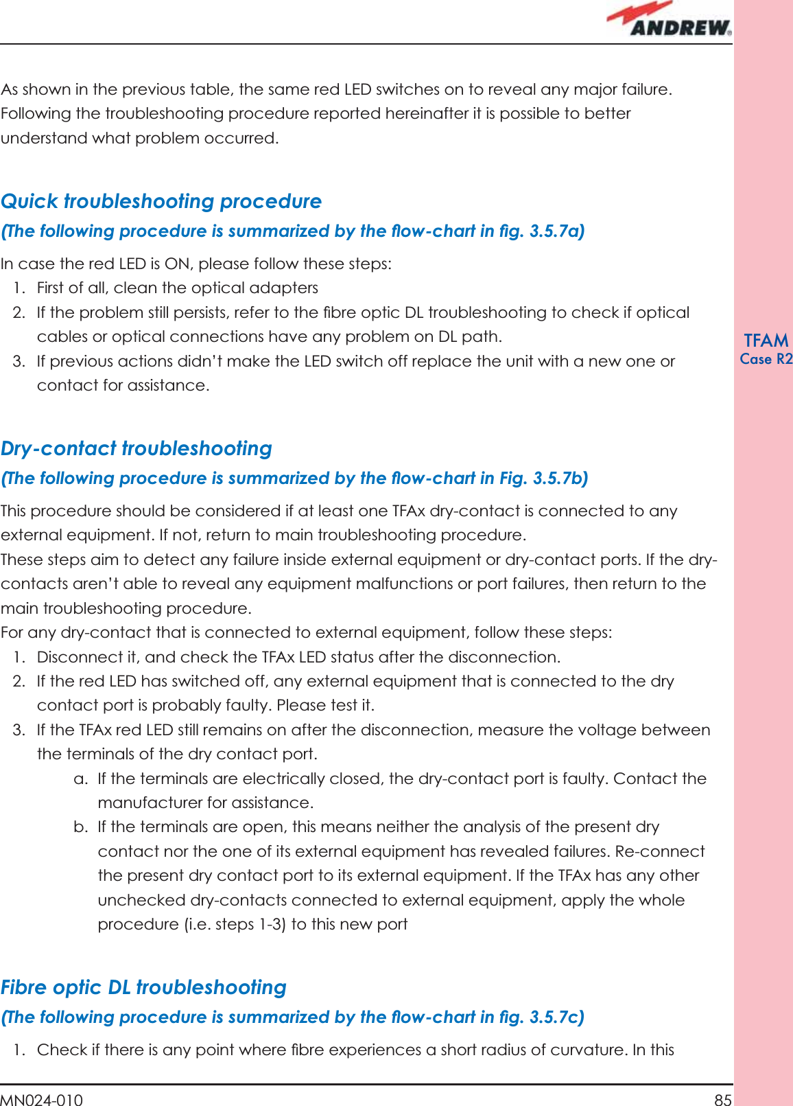
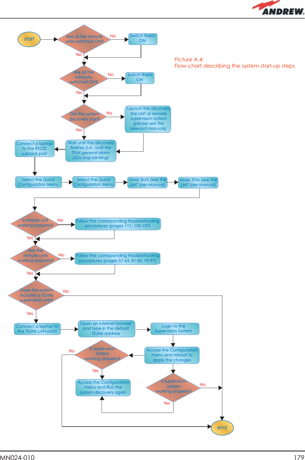
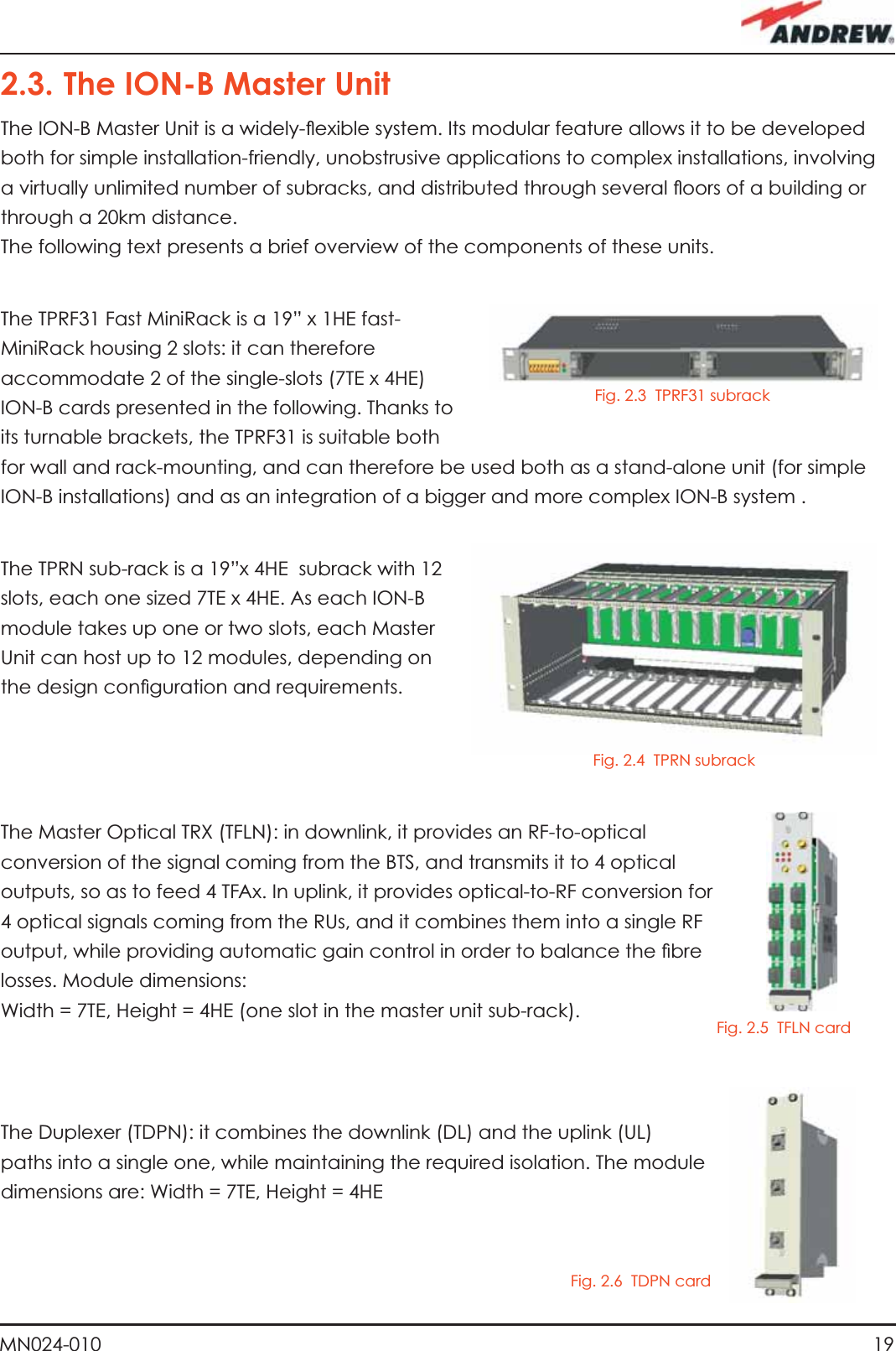
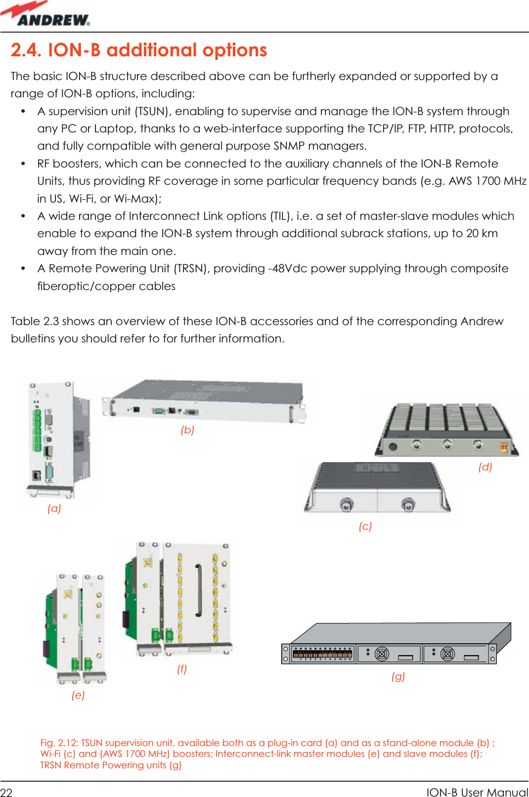
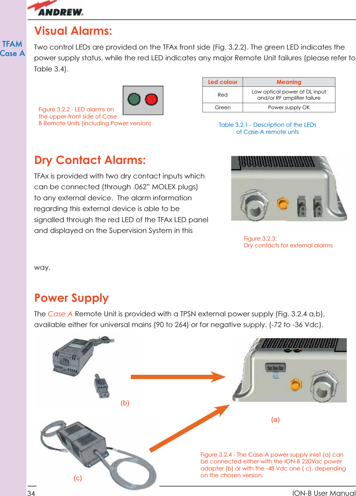
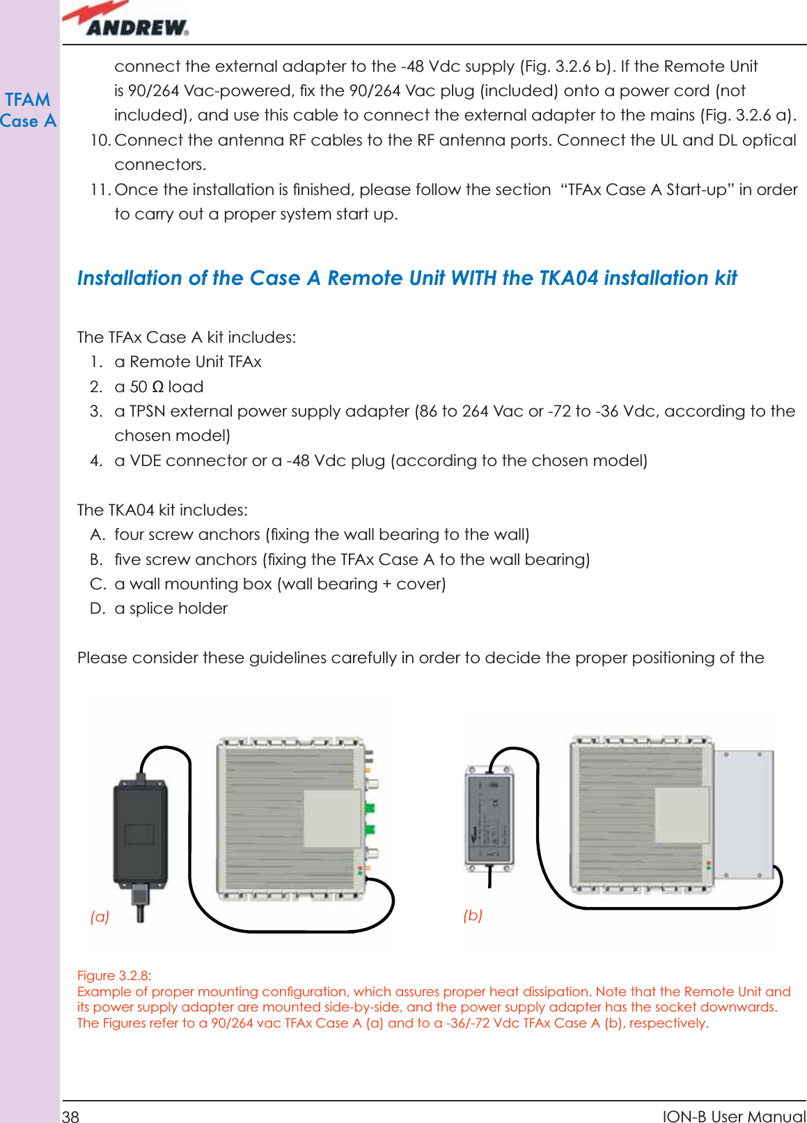
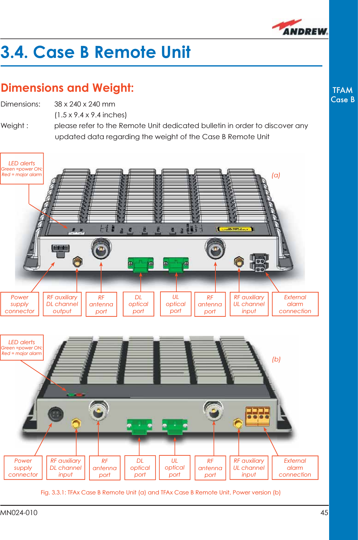
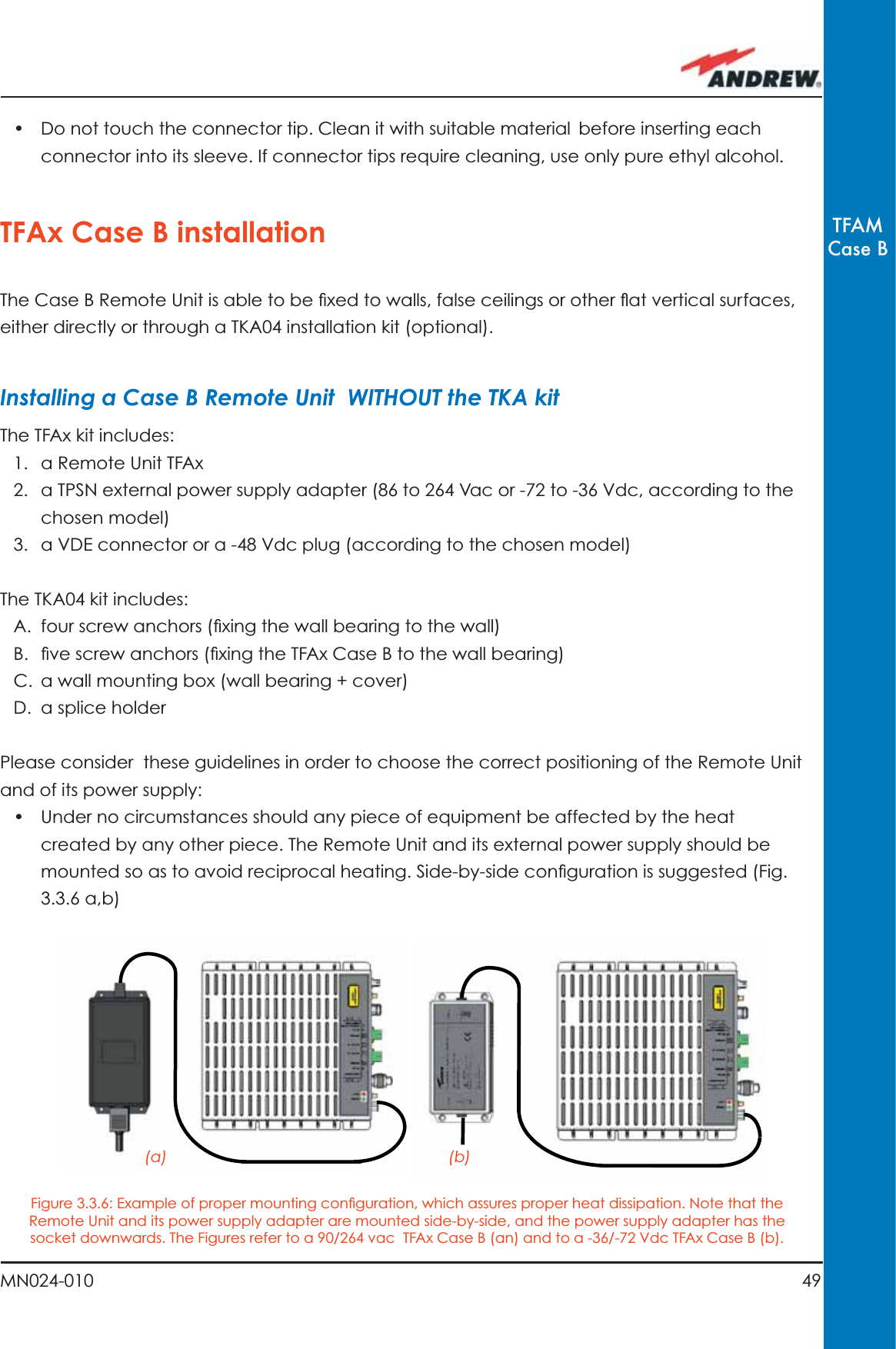
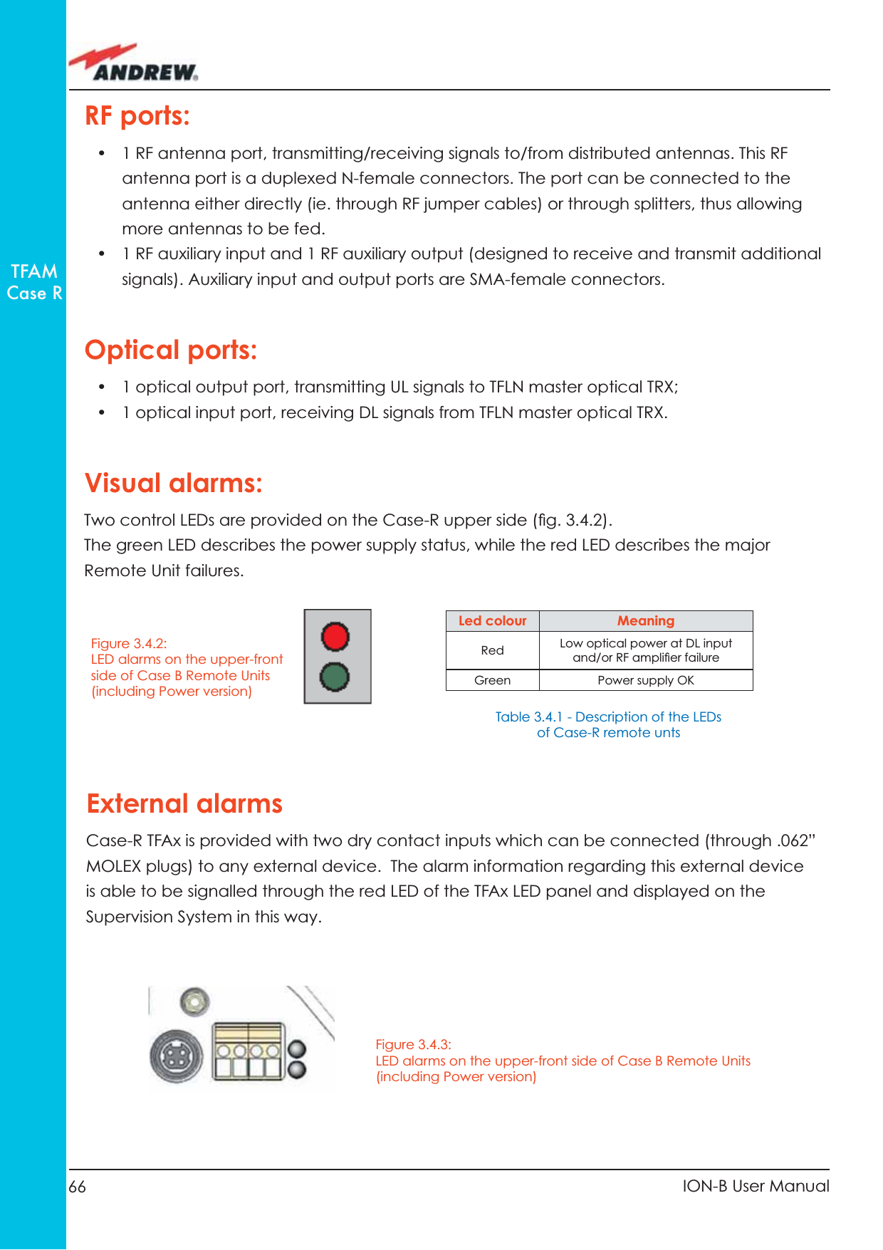
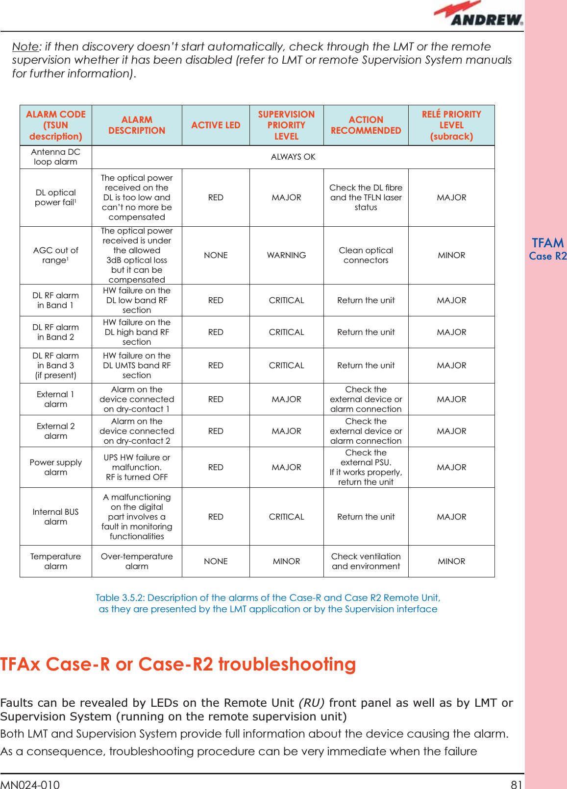
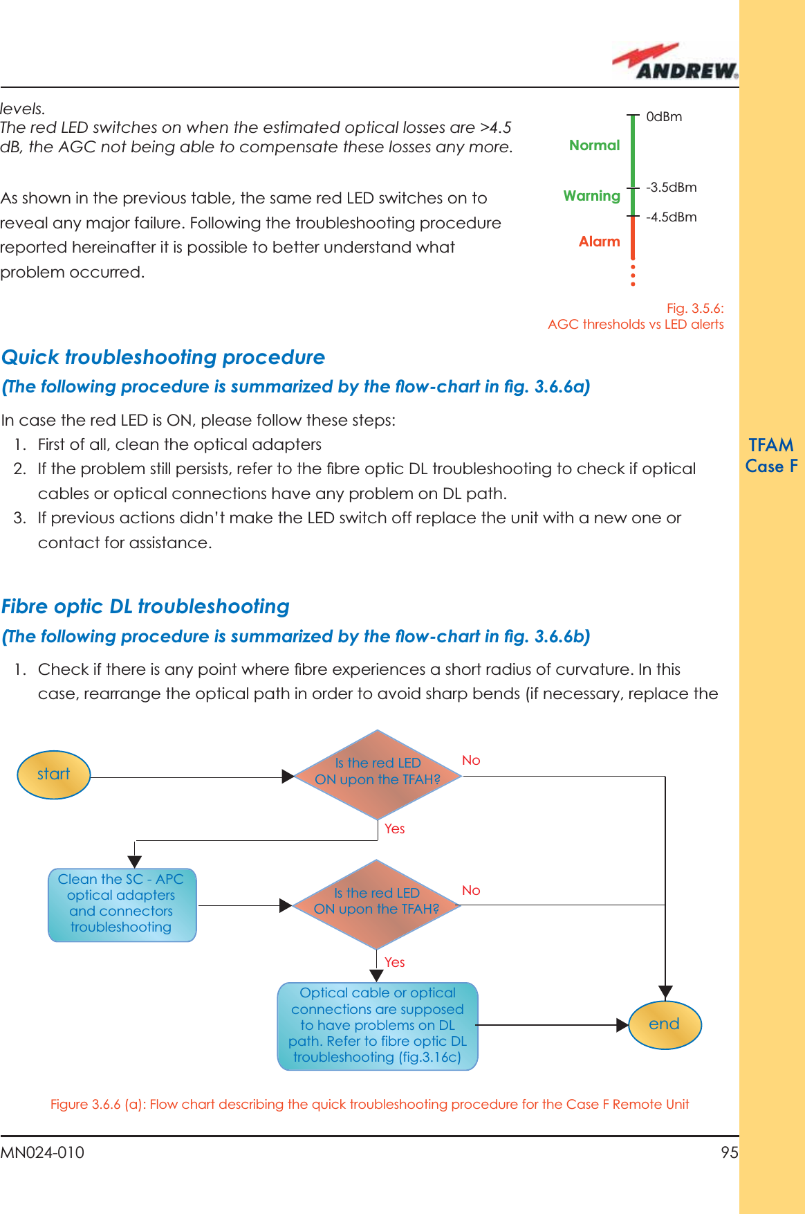
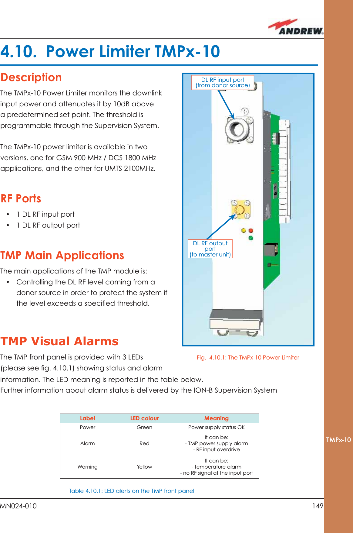
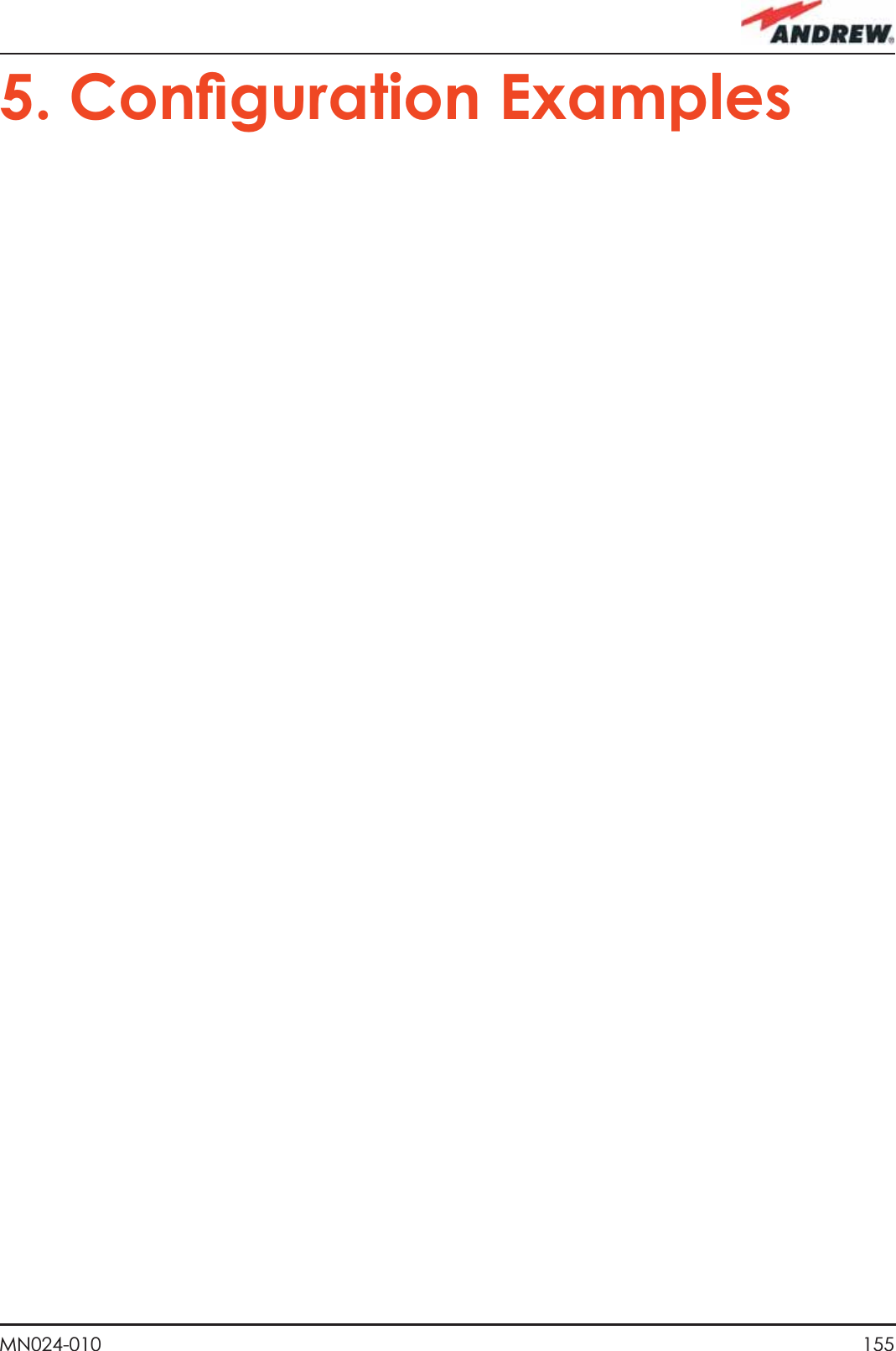
![86 ION-B User ManualTFAMCase R2case, rearrange the optical path in order to avoid sharp bends (if necessary, replace the optical cable with a longer one). If TFLN red LED switches off, troubleshooting has been successfully carried out. Otherwise, follow next steps.2. Check if SC-APC connectors are properly installed at both fi bre ends. In case they are not, fi x better SC-SPC connectors to adapters. If TFLN red LED switches off, troubleshooting has been successful. Otherwise, follow next steps.3. Disconnect the optical fi bre and clean it better at both ends then clean the SC-APC ports on both the TFLN and the Remote Unit. Re-connect the fi bre to relevant ports after cleaning. If it doesn’t made TFLN red LED switch off, follow next steps.4. Disconnect the optical SC-APC connector from Remote Unit DL port, and measure the output power POUT(DL) at the corresponding fi bre end. Then, go to the TFLN side, disconnect the optical SC-APC connector from TFLN DL port and measure the input power PIN(DL) coming out of the TFLN DL port. Calculate the DL fi bre attenuation ADL as ADL [dB] = PIN(DL) – POUT(DL) a. If ADL > 4dB, then the fi bre optic cable has some problems. Replace it with a new one.b. If ADL < 4dB troubleshooting procedure has not identifi ed the problem. Refer to Supervision System or contact assistance.](https://usermanual.wiki/Andrew-Wireless-Innovations-Group/TFAHUS5/User-Guide-898846-Page-86.png)
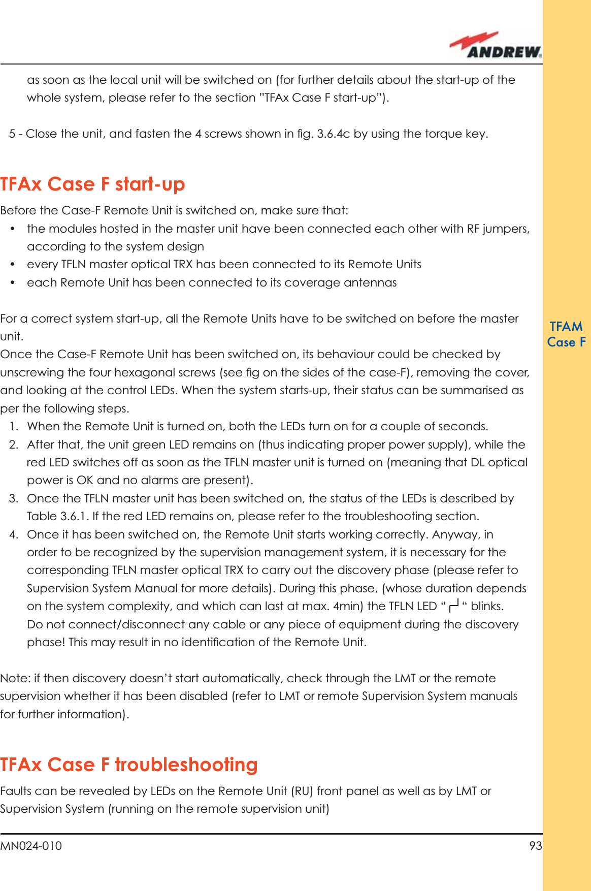
![96 ION-B User ManualTFAMCase FstartendGo to the TFLN sideThe troubleshooting procedure has not identi-fied the problem. Use the supervision system or contact assistanceDisconnect the optical SC-APC connector from the remote unit DL port.Is this dry-contact electrically closed?YesYesYesNoNoNoExternal equipment connected to this dry contact port should be faulty. Test it. Disconnect the optical fiber and clean it at both ends. Is ADL >4dB?Is any dry contact connected to some external equipment?Is the red LEDupon the TFAx still ON??Are SC-APC connectors properly installed at both fiber ends?Fix better the SC-APC connectors.Clean the optical SC-APC ports on both the TFLN and the remote unit. Measure the output power at the corre-sponding fiber ends.Disconnect the optical SC-APC connectors from the TFLN DL portsCalculate the fiber DL attenuation:ADL[dB]=input power - output powerMeasure the input power coming out of the TFLN DL portFiber optic cable has some problems. Please replace itRearrange the optical path to avoid sharp bends. If necessary, replace the optical cable with a longer one Is the red LEDupon the TFAx still ON??NoYesYesNoNoYesFigure 3.6.6 (b): Flow chart describing the fi ber DL troubleshooting](https://usermanual.wiki/Andrew-Wireless-Innovations-Group/TFAHUS5/User-Guide-898846-Page-96.png)
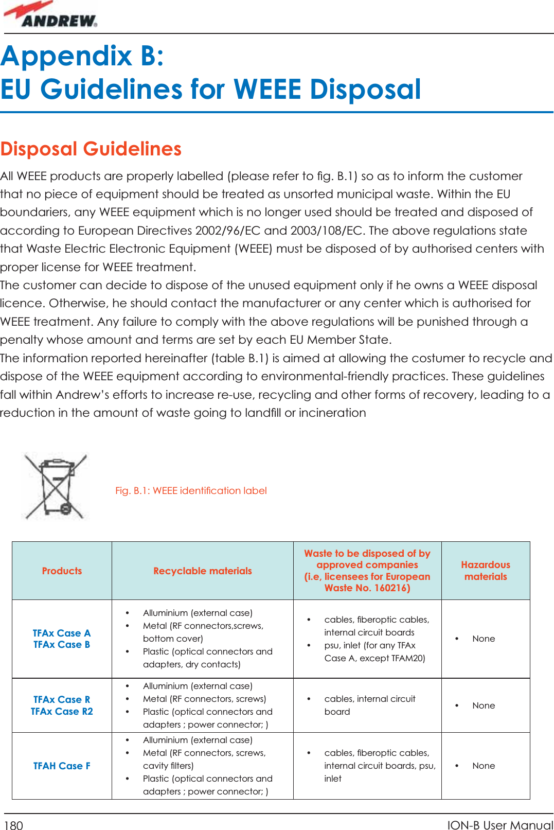
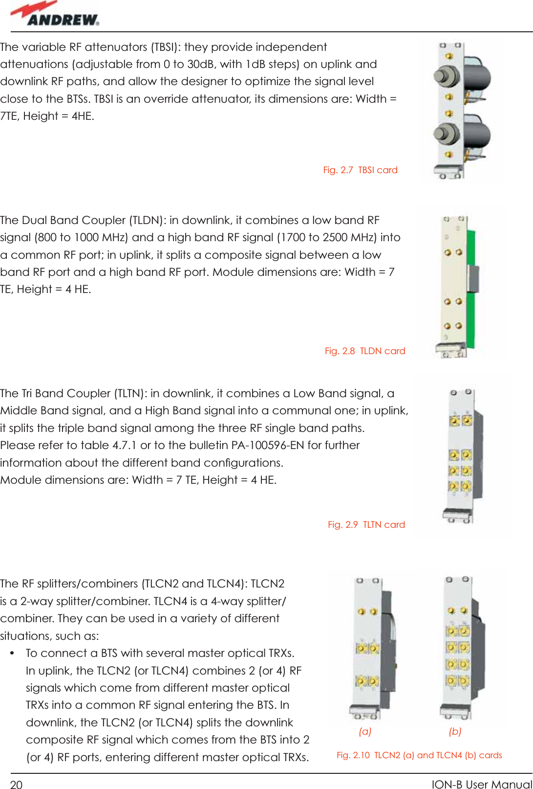
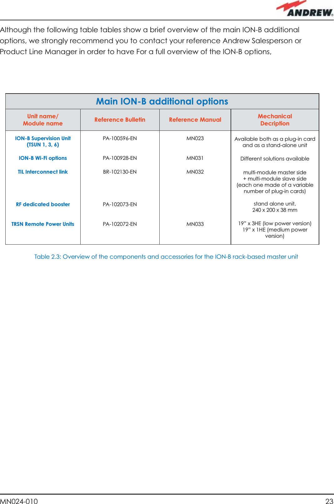
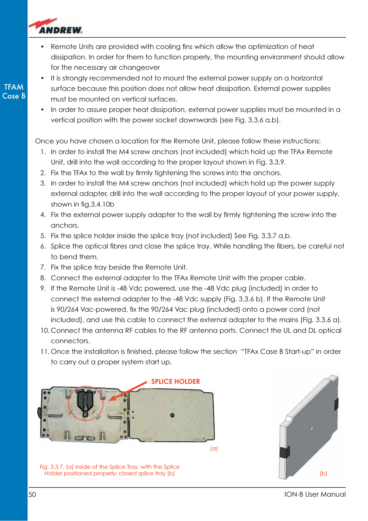
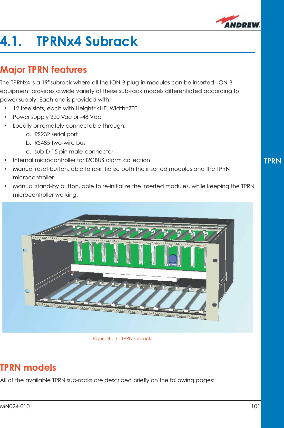
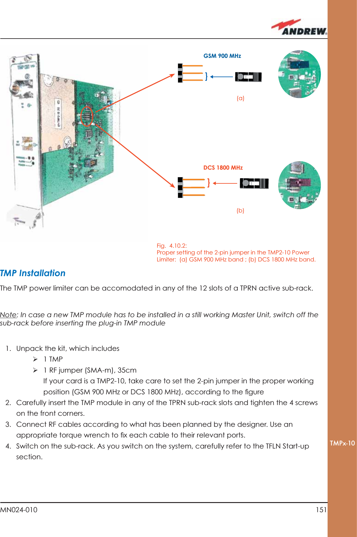
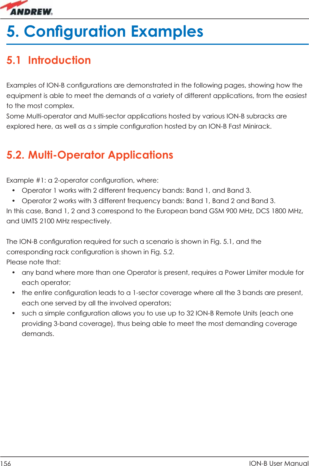
![97MN024-010TFAMCase Foptical cable with a longer one). If TFLN red LED switches off, troubleshooting has been successfully carried out. Otherwise, follow next steps.2. Check if SC-APC connectors are properly installed at both fi bre ends. In case they are not, fi x better SC-SPC connectors to adapters. If TFLN red LED switches off, troubleshooting has been successful. Otherwise, follow next steps.3. Disconnect the optical fi bre and clean it better at both ends then clean the SC-APC ports on both the TFLN and the Remote Unit. Re-connect the fi bre to relevant ports after cleaning. If it doesn’t made TFLN red LED switch off, follow next steps.4. Disconnect the optical SC-APC connector from Remote Unit DL port, and measure the output power POUT(DL) at the corresponding fi bre end. Then, go to the TFLN side, disconnect the optical SC-APC connector from TFLN DL port and measure the input power PIN(DL) coming out of the TFLN DL port. Calculate the DL fi bre attenuation ADL as ADL [dB] = PIN(DL) – POUT(DL) a. If ADL > 4dB, then the fi bre optic cable has some problems. Replace it with a new one.b. If ADL < 4dB troubleshooting procedure has not identifi ed the problem. Refer to Supervision System or contact assistance.](https://usermanual.wiki/Andrew-Wireless-Innovations-Group/TFAHUS5/User-Guide-898846-Page-97.png)


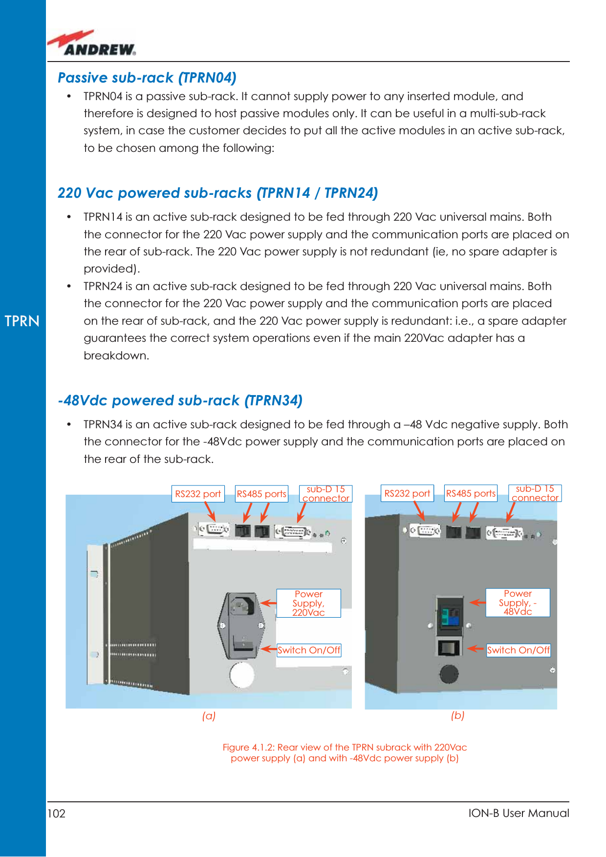
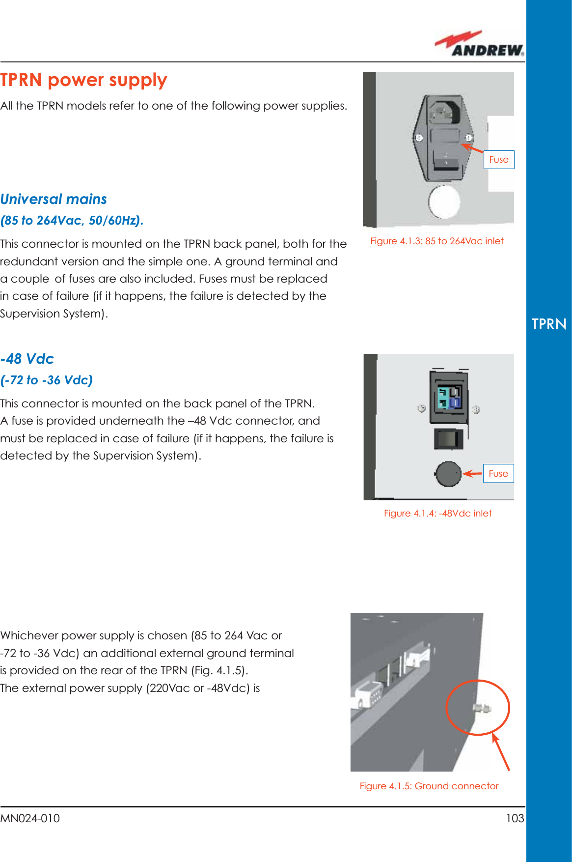
![104 ION-B User ManualTPRNTPRN portsThe TPRN sub-rack is provided with a set of I/0 ports which allows the connection to any external device. RS232 serial portThe RS232 serial port can be used to connect the TPRN sub-rack to the remote supervision unit or to a laptop running LMT software. Please note that a standard RS232 cable is needed.converted to a +12Vdc voltage, feeding the active modules inserted into the TPRN.Baud rate [bps] Dip-switch 59600 OFF19200 ONBaud-rate dip-switch(Dip-switch 5)RS485addressing dip-switches(Dip-switches 1 to 4)FuseBlue terminal: -72 -36 Blue terminal: Switch On/Figure 4.1.6: Rear view of the TPRN subrack with -48Vdc power supply Table 4.1.1: Setting the RS232 baud rate through the dip-switch 5Figure 4.1.7: Dip-switches on the TPRN backplane](https://usermanual.wiki/Andrew-Wireless-Innovations-Group/TFAHUS5/User-Guide-898846-Page-104.png)
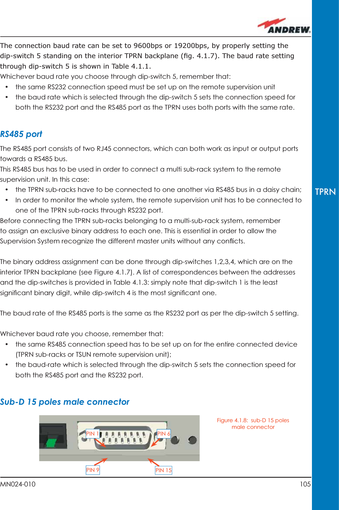

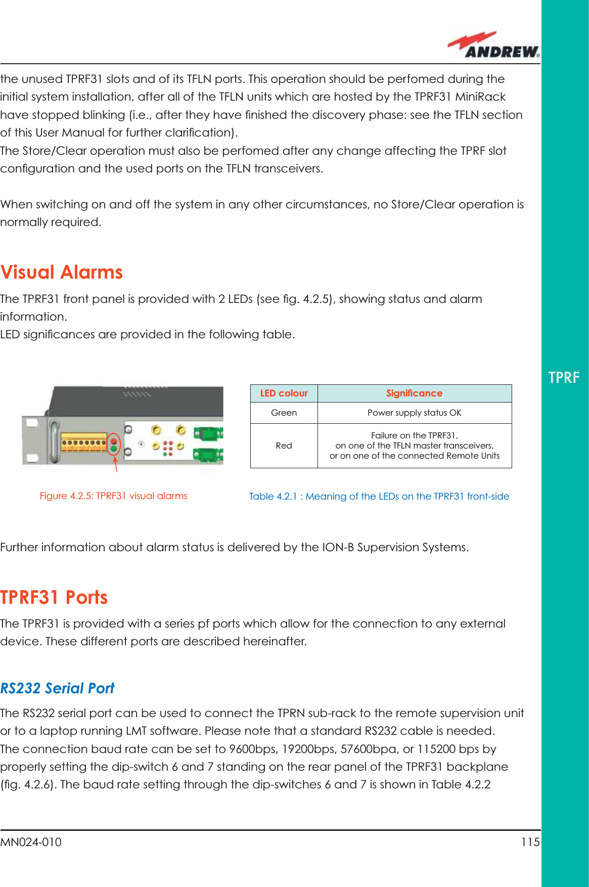
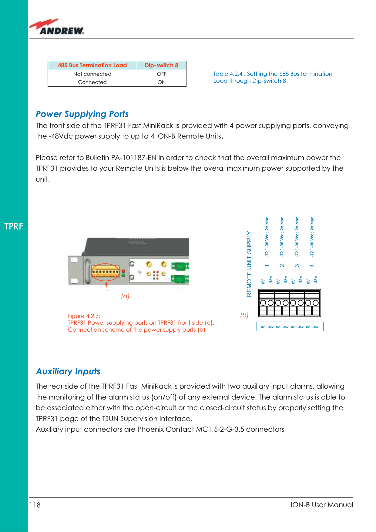
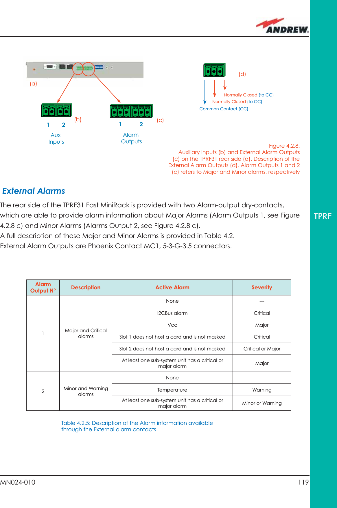
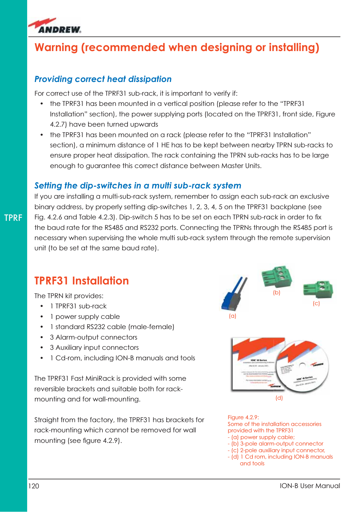
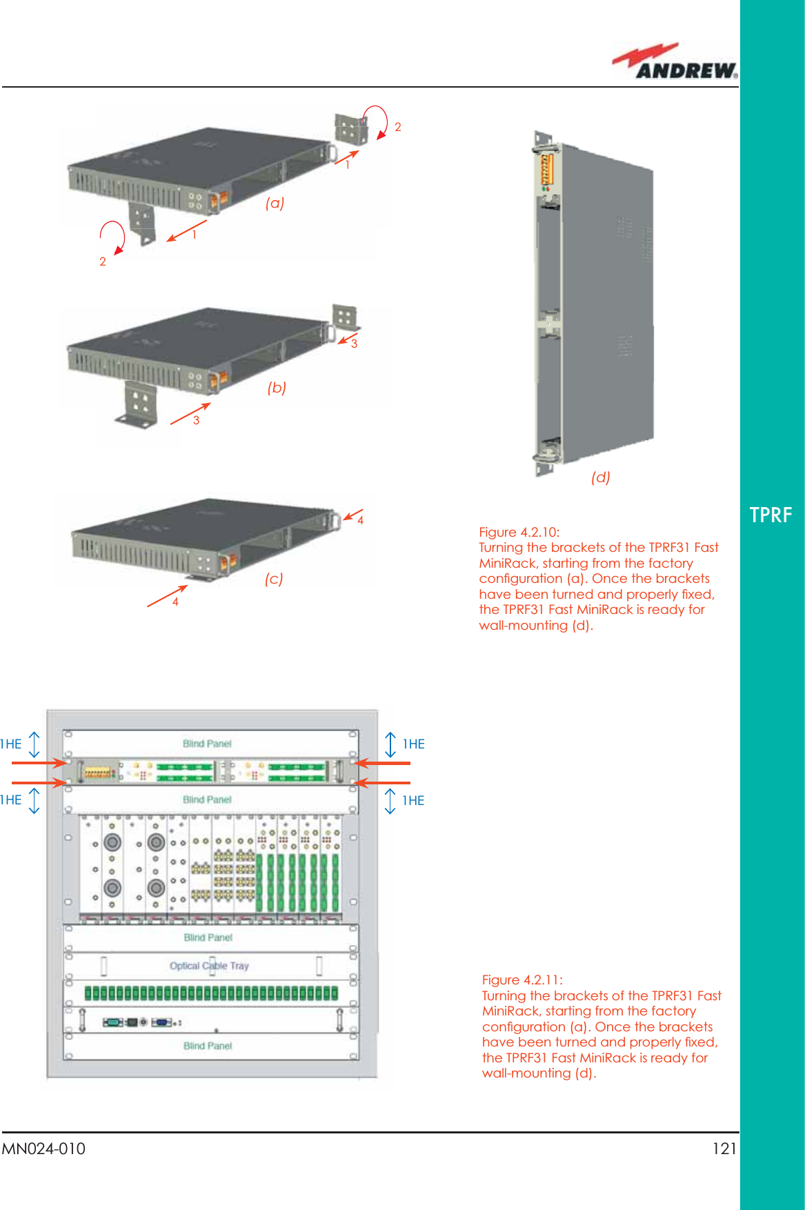
![116 ION-B User ManualTPRF Whichever baud rate you choose through dip-switches 6 and 7, remember that:• the same RS232 connection speed must be set up on the remote supervision unit• the baud rate which is selected through the dip-switches 6 and 7 set the connection speed for both the RS232 port and the RS485 port as the TPRN uses both ports with the same rate.RS485 PortThe RS485 port consists of two RJ45 connectors, which can both work as input or output ports to and from a RS485 bus.This RS485 bus has to be used in order to connect a multi sub-rack system to the remote supervision unit. In this case:• the TPRN sub-racks have to be connected to one another via an RS485 bus in a chain;• In order to monitor the entire system, the remote supervision unit has to be connected to one of the TPRN sub-racks through an RS232 port.Before connecting the TPRN sub-racks belonging to a multi-sub-rack system, remember to assign an exclusive binary address to each one. This is essential in order to let the Supervision System recognize the different master units without any confl ict.The binary address assignment can be done through dip-switches 1, 2, 3, 4 and 5 which are located on the interior TPRN backplane (see Fig 4.2.5). A list of the correspondences between the addresses and the dip-switches is provided in Table 4.2.2: simply note that dip-switch 1 is the least signifi cant binary digit, while dip-switch 5 is the most signifi cant.The baud rate of the RS485 ports is the same as the RS232 port as per the dip-switch 5 setting.Figure 4.2.6 - Dip-switches on the TPRF31 backplaneBaud Rate [bps] Dip-switch 6 Dip-switch 7 9600 OFF OFF 19200 ON OFF57600 OFF ON115200 ON ONTable 4.2.2 - Setting the RS232 baud-rate4 through dip-switches 6 and 71ON](https://usermanual.wiki/Andrew-Wireless-Innovations-Group/TFAHUS5/User-Guide-898846-Page-116.png)

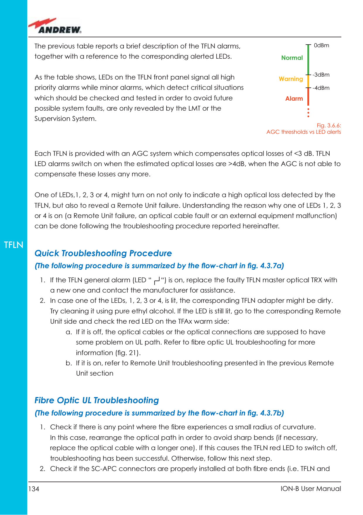
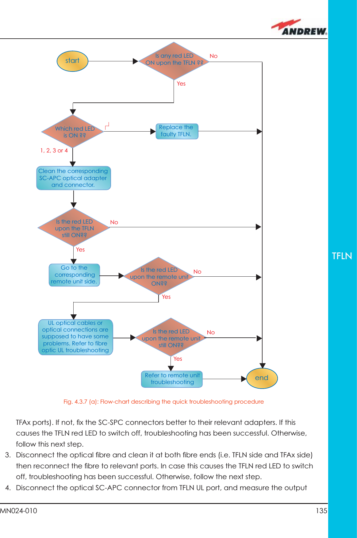
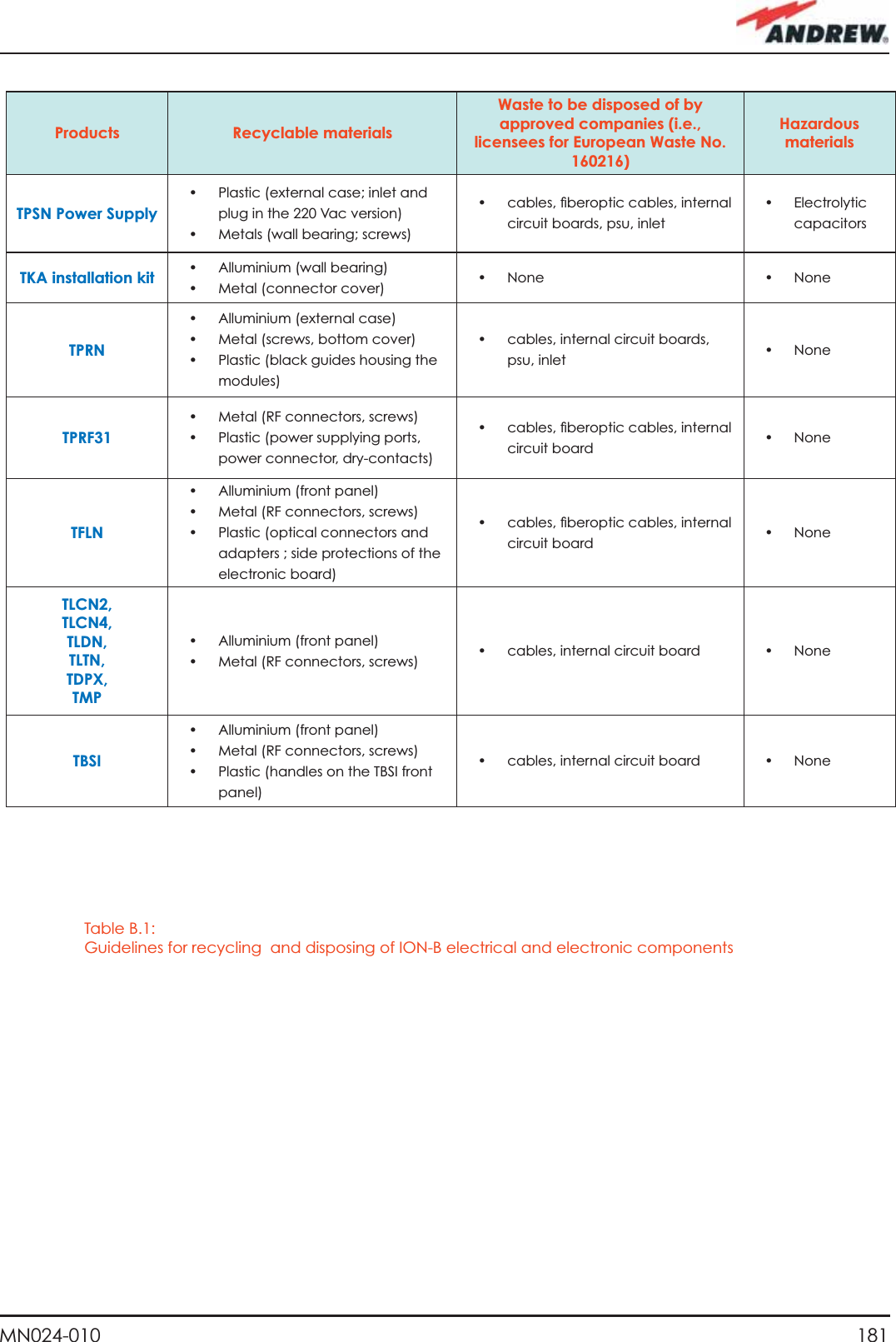
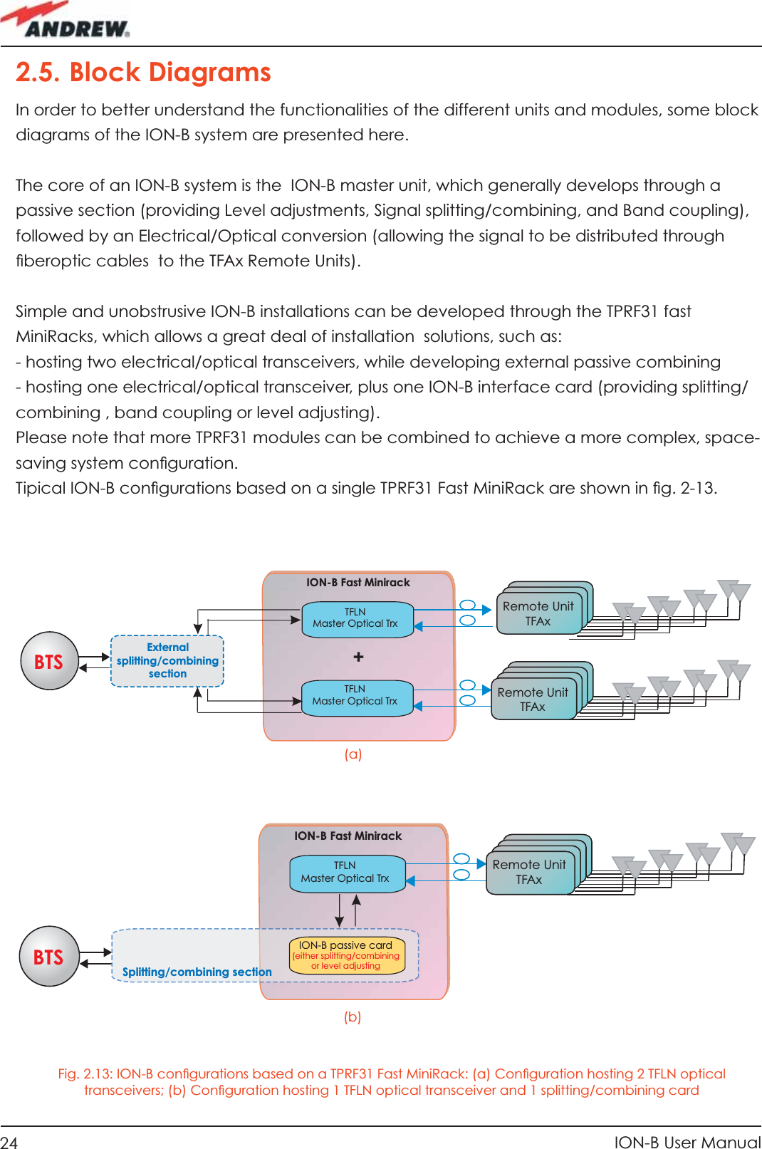
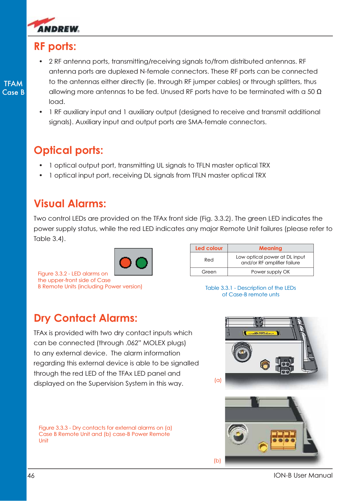
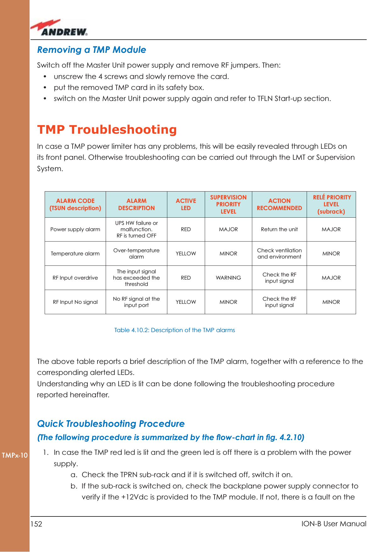
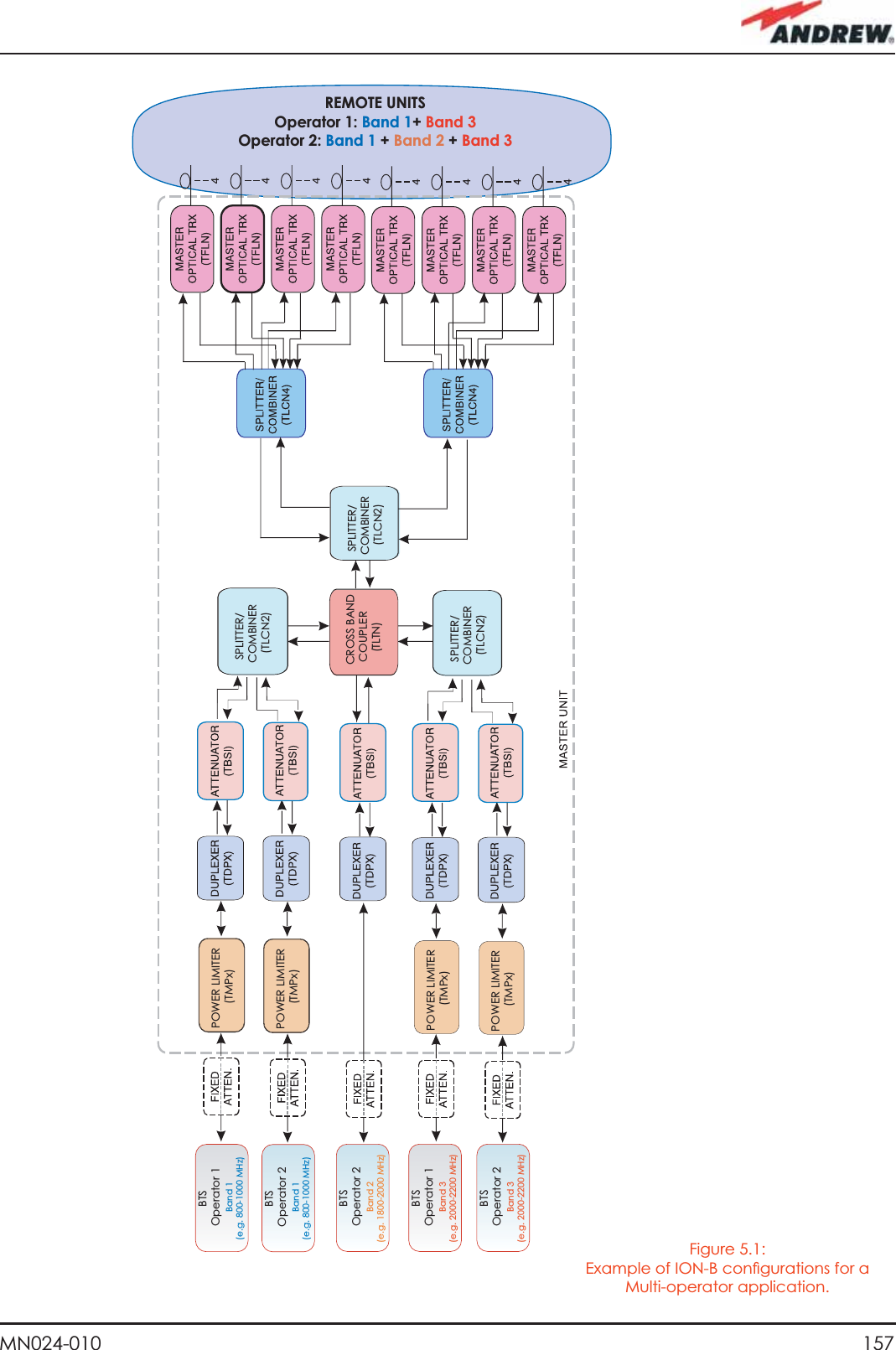
![136 ION-B User ManualTFLNstartendGo to the TFLN sideThe troubleshooting procedure has not identi-fied the problem. Use the supervision system or contact assistanceDisconnect the optical SC-APC connector from the remote unit DL port.Is the red LED upon the remote unit still ON?YesYesYesNoNoNoConnect the fibre optic to its ports again. Disconnect the optical fiber and clean it at both ends. Is ADL >4dB?Is the red LEDupon the remote unit still ON??Are SC-APC connectors properly installed at both fiber ends?Fix better the SC-APC connectors.Clean the optical SC-APC ports on both the TFLN and the remote unit. Measure the output power at the corre-sponding fiber ends.Disconnect the optical SC-APC connectors from the TFLN DL portsCalculate the fiber DL attenuation:ADL[dB]=input power - output powerMeasure the input power coming out of the TFLN DL portFiber optic cable has some problems. Please replace itRearrange the optical path to avoid sharp bends. If necessary, replace the optical cable with a longer one Is the red LEDupon the remote unit still ON??NoYesYesNoNoYesIs there any smallradius of curvatureof the fibre??power POUT(UL) at the corresponding fi bre end. Then, go to the TFAx side, disconnect the optical SC-APC connector from TFAx UL port and measure the input power PIN(UL) coming out of the TFAx UL port.5. Calculate the UL fi bre attenuation AUL as: AUL [dB] = PIN(UL) – POUT(UL)a. If AUL > 4dB, the fi bre optic cable has some problems or the cable path is too long. Replace it.b. If AUL < 4dB, then the TFAx Remote Unit could be faulty. Before replacing it, check the TFAx status on the Supervision System and contact for assistanceFig. 4.3.7 (b): Flow-chart describing the quick troubleshooting procedure](https://usermanual.wiki/Andrew-Wireless-Innovations-Group/TFAHUS5/User-Guide-898846-Page-136.png)


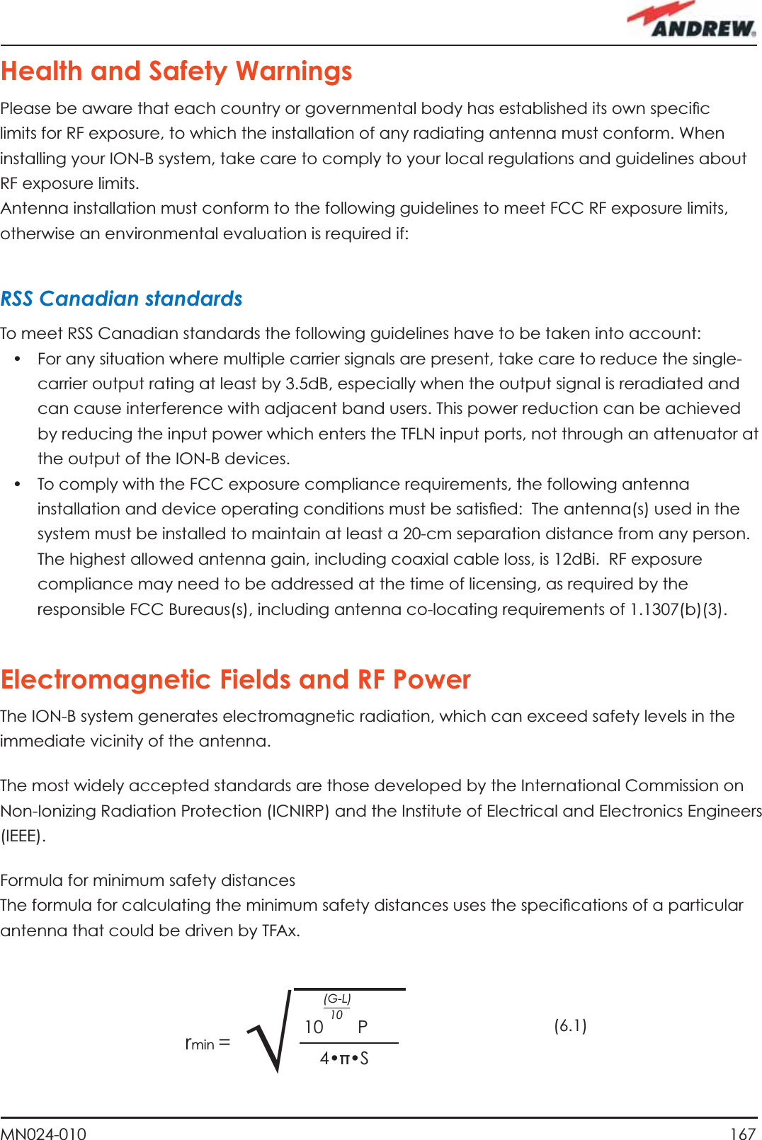
![168 ION-B User ManualThis equation includes the following factors:• G is the antenna gain (in dB) compared to isotropic radiating antennas;• P is the RF power that is present at the antenna connector (in W);• L is the total loss (in dB) between the TFAx remote unit output port and the antenna input port;• S is the maximum allowed power density in air (in W/m2). Its values should be calculated according to the limit exposures to time-variations and magnetic fi elds. The reference values are reported in the ICNIRP guidelines, unless otherwise specifi ed by specifi c regulations. (please note that, if regulations only defi ne the maximum electrical and magnetic fi eld strengths, the allowed power density is able to be be obtained by:S= E2/377= B2·377where 377 is the characteristic’s impedance of the empty space).Example 1. A Medium Power TFAM 18/20P must distribute mobile signals through a directional antenna, fed by a 2-metre length RG223 cable (no splitters used). The antenna gain is 7 dB and the ION-B system distributes one GSM 1800 MHz carrier and one UMTS 2100 MHz carrier.The maximum allowed power density we have to comply with is:S = 10 W m-2(typical ICNIRP reference level for general public exposure to time-varied electric and magnetic fi elds).By reading the relevant notes for the TFAM 18/20P remote unit, we know the overall output power at the antenna port is able to be estimated as follows:• 20 dBm ± 2 ( +22 dBm maximum, equivalent to 0.158 W) for the Cellular 850 MHz band• 20 dBm ± 1.5 ( +21.5 dBm maximum, equivalent to 0.141 W) in the PCS 1900 MHz band. • The total output power at the antenna port is therefore P = 0.158 + 0.141 = 0.299 W.By reading the cable specs, we get that RG223 cable losses can be estimated at 0.55 dB/m. Total losses between the TFAM 18/20P output port and the antenna input port can therefore be estimated as follows: L = 0.55 (dB/m) x 2 (m) = 1.1 dBBy replacing the above values of G, L, P, S parameters inside the formula 6.1, we therefore get the the following minimum safety distance from the antenna: r min = { 10 · exp [ (7 - 1.1) / 10 ] · 0.299} / (4·π·10) } · exp (1/2) = 0.096 m Example 2. A Low Power TFAH85/19 through a directional antenna is used, fed by a 20 -metre length ½” cable, with a 2-way splitter. The antenna Gain is 7 dB and the ION-B system distributes one Cellular 850 MHz carrier and one PCS 1900 MHz carrier.](https://usermanual.wiki/Andrew-Wireless-Innovations-Group/TFAHUS5/User-Guide-898846-Page-168.png)
![169MN024-010The maximum allowed power density we have to comply with is: S = 50 W·m2(typical ICNIRP reference level for occupational exposure to time-varied electric and magnetic fi elds)By reading the ION-B notes, we know that the output power per carrier at the TFAM antenna port is• 30 dBm ± 2 ( +32 dBm maximum, equivalent to 1.202 W) for the Cellular 850 MHz band• 30 dBm ± 2 ( +32 dBm maximum, equivalent to 1.202 W) for the PCS 1900 MHz bandThe ½” cable losses are 0.07 dB/m in the 900 MHz band, and 0.11 dB/m in the 2100 MHz band.The splitter insertion losses are 3.5 dB. The total losses between the TFAH85/19 output port and the antenna input ports can therefore be estimated as follows: L 850MHz = 0.07 (dB/m) x 20 (m) + 3.5 = 4.9 dB for Cellular 850 MHz signals L 1900MHz = 0.10 (dB/m) x 20 (m) + 3.5 = 5.5 dB for PCS 1900 MHz signalsThe term “10 exp (G-L/10) P” which appears inside the formula 6.1 should therefore be calculated seperately for each frequency, and then added in order to calculate the composite contribution: P 850MHz, ant = 10 exp [(7-4.9)/10]· 1.202 = 1.949 W P 1900MHz, ant = 10 exp [(7-5.5)/10]· 1.202 = 1.698 W P composite= P850MHz, ant + P1900MHz,ant = 3.647 WBy dividing the total power through (4·π·S) and taking the square root according to the formula 6.1, we therefore get the the following minimum safety distances from the antenna: r min = { Pcomposite /(4·π·50)} · exp (1/2) = 0.02 mExample 3. There is a Medium Power TFAM91/18/20 which is connected to an omnidirectional antenna through a 10-metre length RG223 cable (no splitters used). The antenna Gain is 7 dB and the ION-B system distributes two GSM900 carriers, two GSM1800carriers, and one UMTS2100 carrier.The maximum allowed electrical fi eld strength is: E = 6 V m(typical Italian reference level for exposure to time-varied electric and magnetic fi elds). The corresponding value of the maximum allowed power density is: S = E2 /377 = 0.1 W/m2By reading the relevant notes for the TFAM 91/18/20 remote unit, the overall output power at the TFAM antenna port can be estimated as follows:• 20 dBm ± 2 ( +22 dBm maximum, equivalent to 0.158 W) for the Cellular 910 MHz:• 21 dBm ± 2 ( +23 dBm maximum, equivalent to 0.200 W) for the GSM1800)](https://usermanual.wiki/Andrew-Wireless-Innovations-Group/TFAHUS5/User-Guide-898846-Page-169.png)
![170 ION-B User Manual• 26 dBm ± 1 ( +27 dBm maximum, equivalent to 0.501 W) in the UMTS band• The total output power at the antenna port is therefore: P = 0.158W x 2 + 0.200W + 0.501W = 1.345 W,By reading the cable specs, we get that RG223 cable losses can be estimated at 0.55 dB/m. Total losses between the TFAM 91/18/20 output port and the antenna input port can therefore be estimated as follows: L = 0.55 (dB/m) x 10 (m) = 5.5 dBBy replacing the above values of G, L, P, S parameters inside the formula 6.1, we therefore get the the following minimum safety distance from the antenna: r min = { 10 · exp [ (7 - 5.5) / 10 ] · 1.345} / (4·π·0.1) } · exp (1/2) = 1.22 m](https://usermanual.wiki/Andrew-Wireless-Innovations-Group/TFAHUS5/User-Guide-898846-Page-170.png)