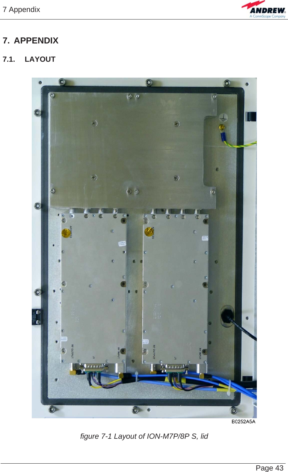
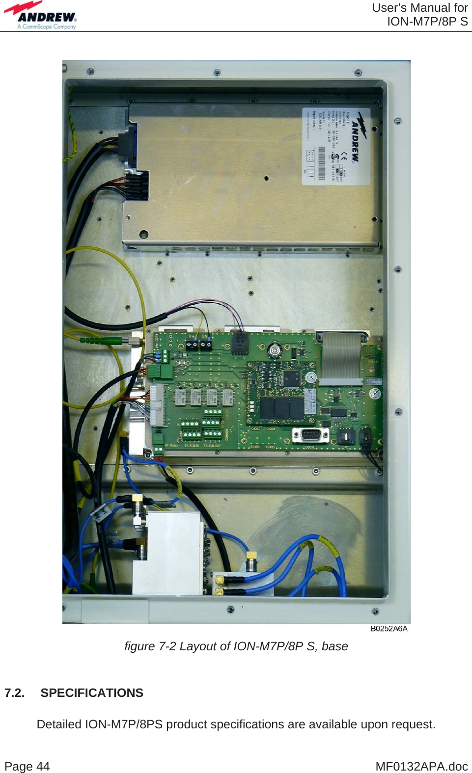
Andrew Wireless System ION-M7P8PS ION-M7P/8P S Repeater User Manual Additional information on SM2009

Andrew Wireless System ION-M7P/8P S Repeater Additional information on SM2009

Users Manual

  ION™-M7P/8P S (Q cabinet)   Optical Remote Unit User's Manual MF0132APA
 User’s Manual forION-M7P/8P S Page 2  MF0132APA.doc                             © Copyright 2010 CommScope, Inc.  All rights reserved. Andrew Solutions is a trademark of CommScope, Inc.  All information contained in this manual has been revised thoroughly. Yet Andrew Solutions accepts no liability for any omissions or faults. Andrew Solutions reserves the right to change all hard- and software characteristics without notice. Names of products mentioned herein are used for identification purposes only and may be trademarks and / or registered trademarks of their respective companies. No parts of this publication may be reproduced, stored in a retrieval system, transmitted in any form or by any means, electronical, mechanical photocopying, recording or otherwise, without prior written permission of the publisher.  Andrew Wireless Systems GmbH, 12-April-2010
   Page 3 TABLE OF CONTENTS 1. GENERAL 7 1.1. USED ABBREVIATIONS  7 1.2. HEALTH AND SAFETY WARNINGS  9 1.3. ABOUT ANDREW SOLUTIONS  11 1.4. INTERNATIONAL CONTACT ADDRESSES FOR WIG CUSTOMER SUPPORT 12 2. INTRODUCTION 15 2.1. PURPOSE 15 2.2. THE ION-M7P/8P S (INTELLIGENT OPTICAL NETWORK; MMR)  15 3. FUNCTIONAL DESCRIPTION  17 3.1. GENERAL 17 3.2. COMPONENTS OF THE ION-M7P/8P S REMOTE UNIT  18 3.3. OPTIONAL EQUIPMENT - RELAY ALARM CONNECTING BOARD  18 4. COMMISSIONING 19 4.1. MECHANICAL INSTALLATION  19 4.1.1. General 19 4.1.2. Wall and Pole Mounting  20 4.2. ELECTRICAL INSTALLATION  21 4.2.1. General 21 4.2.2. Connections 22 4.2.3. Grounding 22 4.2.4. Power Connection  23 4.3. CONNECTION OF THE ANTENNA CABLES  24 4.4. CONNECTION OF THE RF CABLES MAIN UNIT TO COMBINING UNIT  24 4.5. OPTICAL-FIBRE-CABLE CONNECTION - RULES  25 4.5.1. Protective Plug  26 4.5.2. Protective-Tube Kit  28 4.6. COMMISSIONING 30
 User’s Manual for ION-M7P/8P S Page 4  MF0132APA.doc 5. ALARMS 33 5.1. BITE AND ALARMS  33 5.2. HANDLING OF ALARMS  33 5.3. ALARM STATUS  33 5.4. STATUS LED ALARMS  33 5.5. RELAY ALARM CONNECTING BOARD  35 5.5.1. External-Alarm Inputs and Outputs  35 5.5.2. Layout and Connector Description  36 5.6. REDUNDANCY RELAY CONFIGURATION  37 5.7. TROUBLESHOOTING 38 6. MAINTENANCE 39 6.1. GENERAL 39 6.2. OPENING AND CLOSING OF THE CABINET  40 6.3. REPLACEMENT OF POWER SUPPLY  41 6.4. REPLACEMENT OF FAN UNIT  42 7. APPENDIX 43 7.1. LAYOUT 43 7.2. SPECIFICATIONS 44 8. INDEX 45
   Page 5 FIGURES AND TABLES  figure 3-1 Configuration of an ION-M7P/ 8P S.......................................................... 17 figure 3-2 ION-M7P/8P S, lid .................................................................................... 18 figure 3-3 ION-M7P/8P S, base................................................................................ 18 figure 4-1 Wall mounting........................................................................................... 20 figure 4-2 Pole mounting .......................................................................................... 20 figure 4-3 ION-M7P/8P S, connector flange, exemplary........................................... 22 figure 4-4 Grounding bolt.......................................................................................... 22 figure 4-5 AC mains plug .......................................................................................... 23 figure 4-6 DC mains plug.......................................................................................... 23 figure 4-7 Protective-plug assembly ......................................................................... 26 figure 4-8 Tube-kit installation................................................................................... 29 figure 5-1 Alarm triggering ........................................................................................ 34 figure 5-2 Relay alarm connecting board, description of connectors ........................ 36 figure 5-3 Alarm-output contacts, alarm condition .................................................... 37 figure 5-4 Redundancy connection, cabling.............................................................. 37 figure 5-5 Redundancy RF relay............................................................................... 37 figure 5-6 Redundancy connectors, Main Unit and Substitute Unit........................... 37 figure 6-1 Locker with key......................................................................................... 40 figure 6-2 Front and top cover screws ...................................................................... 40 figure 6-3 Power supply screws................................................................................ 41 figure 6-4 Fan unit screws ........................................................................................ 42 figure 6-5 Fan-connector cable................................................................................. 42 figure 7-1 Layout of ION-M7P/8P S, lid .................................................................... 43 figure 7-2 Layout of ION-M7P/8P S, base ................................................................ 44  table 1-1 List of international contact addresses....................................................... 13 table 5-1 Status LED alarms..................................................................................... 34 table 5-2 Relay alarm connecting board connectors, pin assignment....................... 36 table 6-1 Specified torques for various screw types ................................................. 39
 User’s Manual for ION-M7P/8P S Page 6  MF0132APA.doc For your notes:
1 General   Page 7 1. GENERAL 1.1.  USED ABBREVIATIONS  ALC    Automatic Level Control AMPS   American Mobile Phone System or Advanced Mobile Phone System APAC   Automatic Power Adjustment Circuit AWS    Advanced Wireless Services BBU    Battery Backup Unit BCCH   Broadcast Control Channel BITE    Built-In Test Equipment BTS    Base Transceiver Station CDMA   Code Division Multiple Access CEPT   Conférénce Européenne des Postes et Télécommunications CF   Center Frequency CFO    Center Frequency Offset CPD    Channel Power Detection DL   Downlink EDGE   Enhanced Data Rates for GSM Evolution ESD   Electrostatic Discharge ETS   European Telecommunication Standard ETSI   European Telecommunication Standards Institute FCC    Federal Communications Commission FSK    Frequency Shift Keying GSM    Global System for Mobile Communication GUI    Graphical User Interface I2C-Bus  Inter Integrated Circuit Bus (Philips) ID No   Identification Number IF   Intermediate Frequency LMT    Local Maintenance Terminal LNA   Low-Noise Amplifier MIMO   Multiple Input Multiple Output MS   Mobile Station NSO    Network Supervision Option OMC    Operation and Maintenance Center OTRx   Optical Transceiver = SRMU (Subrack Master Unit) PCMCIA  Personal Computer Modem Communication International Association PCS    Personal Communication System PSTN   Public Switched Telephone Network Rev   Revision RF   Radio Frequency RLP   Radio Link Protocol RSSI    Receive Signal Strength Indication RTC   Real-Time Clock RX   Receiver SCL   Serial Clock SDA   Serial Data
 User’s Manual forION-M7P/8P S Page 8  MF0132APA.doc SISO    Single Input Single Output SPD    Switching Point Detector SRMU   Subrack Master Unit = OTRx (Optical Transceiver) TCH   Traffic Channel TDD   Time-Division Duplex TDMA   Time Division Multiple Access TX   Transmitter UL   Uplink UMR    Universal Measurement Receiver UMTS   Universal  Mobile Telecommunication System UPS    Uninterruptible Power Supply VSWR  Voltage Standing Wave Ratio WDM   Wavelength Division Multiplex WIG   Wireless Innovations Group WiMAX  Worldwide Interoperability for Microwave Access
1 General   Page 91.2.  HEALTH AND SAFETY WARNINGS  1.  Only suitably qualified personnel is allowed to work on this unit and only after becoming familiar with all safety notices, installation, operation and maintenance procedures contained in this manual.  2.  Read and obey all the warning labels attached to the unit. Make sure that the warning labels are kept in a legible condition and replace any missing or damaged labels.  3.  Obey all general and regional installation and safety regulations relating to work on high voltage installations, as well as regulations covering correct use of tools and personal protective equipment.  4.  Keep operating instructions within easy reach and make them available to all users.  5.  It is the responsibility of the network provider to implement prevention measures to avoid health hazards which may be associated to radiation from the antenna(s) connected to the unit.  6.  For US and Canadian installations: To comply with FCC RF exposure compliance requirements, the following antenna installation and device operating configurations must be satisfied: A separation distance of at least 4 m must be maintained between the antenna of this device and all persons. RF exposure compliance may need to be addressed at the time of licensing, as required by the responsible FCC Bureau(s), including antenna co-location requirements of 1.1307(b)(3). Maximum permissible antenna gain is 17 dBi.  7.  Make sure access is restricted to qualified personnel.  8.  Only licence holders for the respective frequency range are allowed to operate this unit.  9.  Use this equipment only for the purpose specified by the manufacturer. Do not carry out any modifications or fit any spare parts which are not sold or recommended by the manufacturer. This could cause fires, electric shock or other injuries.  10. Due to power dissipation, the remote unit may reach a very high temperature. Do not operate this equipment on or close to flammable materials.  11. Before opening the unit or (dis-)connecting the mains connector at the remote unit, ensure that mains supply is disconnected.
 User’s Manual forION-M7P/8P S Page 10  MF0132APA.doc12. ESD precautions must be observed! Before commencing maintenance work, use the available grounding system to connect ESD protection measures.  13. This unit complies with European standard EN60950.  14. Make sure the system settings are according to the intended use (see also product information of manufacturer) and regulatory requirements are met.  15. Although the remote unit is internally protected against overvoltage, it is strongly recommended to earth the antenna cables close to the antenna connectors of the remote unit for protection against atmospheric discharge.  16. Laser radiation – Class 1! Do not stare into the beam; do not view it directly or with optical instruments.
1 General   Page 11 1.3.  ABOUT ANDREW SOLUTIONS  Andrew Wireless Systems GmbH based in Buchdorf/ Germany, is a leading manufacturer of coverage equipment for mobile radio networks, specializing in low cost, high performance, RF and optical repeaters. Our optical distributed networks and RF repeater systems provide coverage for every application: outdoor use, indoor installations, tunnels, subways and many more.  Andrew Wireless Systems GmbH belongs to the Wireless Innovations Group (WIG). Being a part of Andrew Solutions, WIG has unparalleled experience in providing RF coverage and capacity solution for wireless networks in both indoor and outdoor environment.  Andrew Solutions, a CommScope Company, is the foremost supplier of one-stop, end-to-end radio frequency (RF) solutions. Our products are complete solutions for wireless infrastructure from top-of-the-tower base station antennas to cable systems and cabinets, RF site solutions, signal distribution, and network optimization.  Andrew Solutions has global engineering and manufacturing facilities. In addition, it maintains field engineering offices throughout the world.  We operate a quality management system in compliance with the requirements of ISO 9001. All equipment is manufactured using highly reliable material. In order to ensure constant first-rate quality of the products, comprehensive quality monitoring is conducted at all fabrication stages. Finished products leave the factory only after a thorough final acceptance test, accompanied by a test certificate guaranteeing optimal operation.  The declaration of conformity for the product is available upon request from the local sales offices or from Andrew Solutions directly.  To make the utmost from this unit, we recommend you carefully read the instructions in this manual and commission the unit only according to these instructions.  For technical assistance and support, contact the local office or Andrew Solutions directly at one of the following addresses listed in the next chapter.
 User’s Manual forION-M7P/8P S Page 12  MF0132APA.doc 1.4.  INTERNATIONAL CONTACT ADDRESSES FOR WIG CUSTOMER SUPPORT  Wireless Innovations Group (WIG)  Americas: Canada United States Andrew Solutions Canada  Andrew Solutions,  Andrew LLC, A CommScope CompanyMail 620 North Greenfield Parkway Garner, NC 27529 U.S.A. Mail  620 North Greenfield Parkway Garner, NC 27529 U.S.A. Phone +1-905-878-3457 (Office) +1 416-721-5058 (Mobile) Phone +1-888-297-6433 Fax +1-905-878-3297  Fax  +1-919-329-8950 E-mail Peter.Masih@andrew.com WIsupport.us@andrew.com  E-mail WIsupport.us@andrew.com  Brazil & South America  Mexico, Central America &  Caribbean region Andrew Solutions,  A CommScope Company  Andrew Solutions Mexico Mail Av. Com. Camilo Julio 1256 Predio B Zonal Industrial CP 597 Sorocaba SP 18086-000 Brazil Mail Monte Elbruz 124-402A Col. Palmas Polanco 11560 Mexico, D.F. Mexico Phone  + 55-15-9104-7722  Phone  + 52-55-1346-1900 (Office) +52-1-55-5419-5260 (Mobile) Fax  + 55-15-2102-4001  Fax  +52-55-1346-1901 E-mail WIsupport@andrew.com  E-mail WIsupport@andrew.com  APAC Countries:  China Australia Andrew Solutions Hong Kong  Andrew Corporation (Australia) LLC Pty Ltd. Mail Room 915  Chevalier Commercial Centre 8 Wang Hoi Rd Kowloon Bay SAR Hong Kong Mail Unit 1 153 Barry Road Campbellfield  VIC  3061 Australia Phone +852-310-661-00  Phone +613-9300-7969 Fax +852-2751-7800  Fax +613-9357-9110 E-mail WISupport.china@andrew.com  E-mail WIsupport.australia@andrew.com
1 General   Page 13 Europe:  United Kingdom  France Andrew Solutions UK Ltd  Andrew Solutions France Mail Unit 15, Ilex House  Mulberry Business Park Fishponds Road  Wokingham Berkshire RG41 2GY England Mail 28, Rue Fresnel Z.A Pariwest BP 182 78313 Coignières Cedex France Phone  +44-1189-366-792  Phone  +33 1 30 05 45 50 Fax  +44-1189-366-773  Fax  +33 1 34 61 13 74 E-mail  WIsupport.uk@andrew.com E-mail WIsupport@andrew.com  Germany Czech Republic Andrew Wireless Systems GmbH  Andrew Solutions Czech Republic C-Com, spol. s r.o Mail  Industriering 10 86675 Buchdorf Germany  Mail  U Moruší 888 53006 Pardubice Czech Republic Phone  +49-9099-69-0  Phone  +420-464-6280-80 Fax  +49-9099-69-930  Fax  +420-464-6280-94 E-mail WIsupport@andrew.com  E-mail WIsupport@andrew.com  Austria Switzerland Andrew Wireless Systems (Austria) GmbH  Andrew Wireless Systems AG Mail  Weglgasse 10 Wien-Schwechat 2320 Austria Mail  Tiergartenweg 1 CH-4710 Balsthal Switzerland Phone  +43-1706-39-99-10  Phone +41-62-386-1260 Fax  +43-1706-39-99-9  Fax +41-62-386-1261 E-mail WIsupport.austria@andrew.com  E-mail support.ch@andrew.com  Italy  Spain & Portugal Andrew Wireless Systems S.r.l., Faenza, Italy  Andrew Solutions España S.A. Mail  Via de Crescenzi 40 Faenza 48018 Italy  Mail  C/ Salvatierra, 5 - 3a pt. 28034 Madrid Spain Phone  +39-0546-697111  Phone  +34-91-745-20 40 Fax  +39-0546-682768  Fax  +34-91-564-29 85 E-mail WIsupport.italia@andrew.com  E-mail WIsupport.iberia@andrew.com table 1-1 List of international contact addresses
 User’s Manual forION-M7P/8P S Page 14  MF0132APA.doc For your notes:
2 Introduction   Page 15 2. INTRODUCTION 2.1.  PURPOSE  Cellular telephone systems transmit signals in two directions between a base transceiver station (BTS) and mobile stations (MS) within the signal coverage area.  If weak signal transmissions occur within the coverage area because of indoor applications, topological conditions or distance from the transmitter, extension of the transmission range can be achieved by means of an optical distribution system.  Such a system contains an optical master unit and several remote units. The number of the remote units depends on the hardware and software configuration. The remote units are connected to the master unit with optical links. The optical loss must be less than 10 dB inclusive optical couplers or splitters.  The master unit is the connection to the base transceiver stations. The configuration of a master unit depends on the number of the remote units and the frequency range.   The optical transmission uses WDM-systems with a wavelength of 1550 nm in the uplink and 1310 nm in the downlink.  2.2.  THE ION-M7P/8P S (INTELLIGENT OPTICAL NETWORK; MMR)  The Andrew ION-M7P/8P S is a multi-operator remote unit with various extension units. It is used in conjunction with a master unit in the ION optical distribution system. This system transports the entire 700 MHz public safety and 800 MHz LMR frequency bands simultaneously, providing a cost-efficient solution for distributing capacity from one or more base stations.  The ION-M7P/8P S transports signals on the RF layer in a very inexpensive manner. This means that multiple operators and multiple technologies are moved simultaneously from a cluster of base stations to a remote location over the same fiber.  The ION optical distribution system is a cost-effective coverage solution for dense urban areas, tunnels, subway, airports, convention centers, high-rise buildings and other locations where physical structures increase path loss. It has been specifically designed to reduce zoning problems and to provide homogeneous coverage. The compact, mechanical design is specifically architected to mount at poles or along side structures in such a way that it has a minimum visual impact.  The ION-M7P/8P S performance is available both in single or multi-band configuration supporting 700 MHz, and 800 MHz in parallel. It has been specifically tested and optimized for TDMA, CDMA2000, and WCDMA. Furthermore it is provisioned for future improvements to modulations (e.g. HSPA, EV-DO and OFDM) and frequency bands. In addition it is backwards compatible to legacy standards such as Analog.
 User’s Manual forION-M7P/8P S Page 16  MF0132APA.doc  The ION is easily set-up and supervised via a graphical user interface (GUI). Remote units can be commissioned through the use of built-in test equipment. An auto leveling function compensates for the optical link loss making installation easy and quick. The entire system may be monitored remotely via an Andrew OMC. This is a comprehensive management platform with SNMP protocol and X.733 standard implemented. Should a sophisticated interface not be required, the master unit can be directly connected to the alarm interface of a base station via relay alarming.  Features:     Multi-band, multi-operator support    Reduced visual impact form factor    High, efficient power amplifier    Single fiber for multiple bands and multiple remotes    Comprehensive operations and management system for configuration and alarming    OMC with SNMP according to X.733 standard    Easy installation and commissioning    Redundancy configuration option
3 Functional Description   Page 173. FUNCTIONAL DESCRIPTION 3.1.  GENERAL  The following figure shows the configuration of an ION-M7P/8P S:   Power Amplifier 1+28 VDCI²CoeoeDLULUL/DLWDM OTRXfrom / to Master UnitOptical Module DrawerModule+28 VDCI²CPower Amplifier 1+28 VDCI²CControl UnitC161 core moduleAlarmboard w. relaysDrawerPSUDrawerModuleMains+28 VDCI²CANT DLUL LNADrawerModule Ext. Al inExt. Al out28V E3202B0Crossband Coupler (CC)Part of output CCCrossband Coupler (CC)Drawer ModuleDrawer DrawerANT ULSubrack  figure 3-1 Configuration of an ION-M7P/ 8P S
 User’s Manual forION-M7P/8P S Page 18  MF0132APA.doc3.2.  COMPONENTS OF THE ION-M7P/8P S REMOTE UNIT  The actual configuration of the remote unit can be seen at the configuration list which is part of the delivery.  The following figure shows an exemplary view of an ION-M7P/8P S remote unit to illustrate the individual components.   figure 3-2 ION-M7P/8P S, lid  figure 3-3 ION-M7P/8P S, base Power   3.3.  OPTIONAL EQUIPMENT - RELAY ALARM CONNECTING BOARD  For further information on the relay alarm connecting board please refer to chapter 5.5 Relay Alarm Connecting Board.  Control unit Optical interface Final amplifiers Relay alarm connecting board supply Crossband coupler RF relay
4 Commissioning   Page 194. COMMISSIONING 4.1.  MECHANICAL INSTALLATION 4.1.1.  General  Read the health and safety warnings in chapter 1.2 Health and Safety Warnings.  1. Do not install the unit in a way or at a place where the specifications outlined in the Environmental and Safety Specifications leaflet of the manufacturer are not met.  2. It is strongly recommended to install the unit vertically. If a different installation of the remote unit is required, please contact customer service for further information.  3. It is recommended only to use the mounting hardware delivered by the manufacturer. If different mounting hardware is used, the specifications for stationary use of the remote unit must not be exceeded.  ) Note:  Exceeding the specified load limits may cause the loss of warranty!  4.  The unit is considerably heavy. Make sure that a suitable mounting surface is used. Ensure there is adequate manpower to handle the weight of the system.  5. Due to power dissipation, the remote unit may reach a very high temperature. Ensure sufficient airflow for ventilation. Above and below the unit a minimum distance of 300 mm to ceiling, floor, etc. has to be kept. Also observe the instructions in the individual mounting procedures.  6.  For outdoor installations, the pre-mounted front cover must be installed.  7.  For indoor installations where the ambient temperature can reach above 40°C, the cover has to be removed.  8.  When connecting and mounting the cables (RF, optical, mains, ...) ensure no water can penetrate into the unit through these cables.  If any different or additional mounting material is used, ensure that the mounting remains as safe as the mounting designed by the manufacturer. Ensure that the static and dynamic strengths are adequate for the environmental conditions of the site. The mounting itself must not vibrate, swing or move in any way that might cause damage to the remote unit.
 User’s Manual forION-M7P/8P S Page 20  MF0132APA.doc4.1.2.  Wall and Pole Mounting  Wall and pole mounting equipment for the unit is available. For the according mounting please refer to the mounting plan (drawing) that is part of the delivery.    figure 4-1 Wall mounting  figure 4-2 Pole mounting V1628M1 V1628M0
4 Commissioning   Page 214.2.  ELECTRICAL INSTALLATION 4.2.1.  General  Read the health and safety warnings in chapter 1.2 Health and Safety Warnings. 1. This unit contains dangerous voltages. Loss of life, severe personal injury or property damage can be the result if the instructions contained in this manual are not followed. 2.  It is compulsory to ground the unit before connecting power supply. A grounding bolt is provided on the cabinet to connect the ground-bonding cable. 3.  Although the remote unit is internally protected against overvoltage, it is strongly recommended to earth the antenna cables close to the antenna connectors of the remote unit for protection against atmospheric discharge. In areas with strong lightning it is strongly recommended to insert additional lightning protection. 4.  If the mains connector of the remote unit is not easily accessible, a disconnect device in the mains circuit must be provided within easy reach. 5. Before connecting or disconnecting the mains connector at the remote unit, ensure that mains supply is disconnected. 6.  Make sure that an appropriate circuit breaker and an overcurrent limiting device are connected between mains and remote unit. 7.  A connection of mains supply to a power socket requires the power socket to be nearby the remote unit. 8. Incorrectly wired connections can destroy electrical and electronic components. 9.  To avoid corrosion at the connectors caused by electrochemical processes, the material of the cable connectors must not cause a higher potential difference than 0.6 V (see electrochemical contact series). 10. It is sufficient to tighten 7/16-antenna connectors hand-screwed. Any use of a tool (e.g. pair of pliers) might cause damage to the connector and thus lead to malfunctioning of the remote unit. 11. For unstabilized electric networks which frequently generate spikes, it is advised to use a voltage limiting device.  12. The unit complies with the surge requirement according to EN 61000-4-5 (fine protection); however, it is recommended to install an additional medium (via local supply connection) and/or coarse protection (external surge protection) depending on the individual application in order to avoid damage caused by overcurrent. 13. Observe the labels on the front panels before connecting or disconnecting any cables.
 User’s Manual forION-M7P/8P S Page 22  MF0132APA.doc4.2.2.  Connections    figure 4-3 ION-M7P/8P S, connector flange, exemplary  4.2.3.  Grounding  Grounding must be carried out. Connect an earth-bonding cable to the grounding connection provided at the outside of the remote unit (see chapter 4.2.2 Connections). Do not use the grounding connection to connect external devices.    figure 4-4 Grounding bolt  Optical connector Status LED Mains connector Connector to Substitute Unit Connectors to main unit AUX   BBU connector connector N-antenna connectors Connectors to Redundant RU
4 Commissioning   Page 23 After loosening the hex nut, connect the earth-bonding cable between the two washers as illustrated in the figure above. Then, fasten all parts again with the hex nut.   The PE cables must have a minimum cross section of 16mm2.  4.2.4.  Power Connection  Before connecting electrical power to the units, the system must be grounded as described in the previous chapter.  Mains power must be connected at the mains connector of the unit (see chapter 4.2.2 Connections).  The power supply plug is part of the delivery. The correct wiring of the power supply plug is as follows:    figure 4-5 AC mains plug  figure 4-6 DC mains plug    For the AC power supply connection, a minimum cross section of 1.5 mm2 is required and for the DC power supply connection, a minimum cross section of 2.5 mm2 is required. Each wire must observe the applicable national regulations regarding loop impedance, voltage drop, and methods of installation. Make sure to connect the correct voltage to the unit.
 User’s Manual forION-M7P/8P S Page 24  MF0132APA.doc ) Note:  Do not connect or disconnect the power cord at the mains connector while power is on. Turn off mains * power before connecting the power cord at the remote unit, then, engage mains again. *  Mains power must be interrupted with an external mains breaker. For the mains breaker, observe the following recommendation:  120 Volt / 20 Amp max. or 240 Volt / 16 Amp, single-phase, 50 / 60 Hz AC service is needed, i.e. the external AC breaker should be 20 Amps max. for 120-Volt service or 16 Amps for 240-Volt service. For the DC power supply, observe the local regulations of the DC service provider.  4.3.  CONNECTION OF THE ANTENNA CABLES  The Main Unit has N connectors. For its location, please refer to chapter 4.2.2 Connections. However, the Combining Unit has 7/16 antenna connectors (described in separate manual). For mounting the cable connectors, it is recommended to refer to the corresponding documentation of the connector manufacturer. The bending radius of the antenna cables must remain within the given specifications.   For the selection of cable and antenna it should be considered that, on the one hand, a cable with higher loss is less expensive but, on the other hand, it impairs performance.   It is sufficient to tighten the 7/16 antenna connectors of the Combining Unit hand-tight. The use of a tool (like pliers) may cause damage to the connector and, therefore, lead to a malfunctioning of the remote unit.  4.4.  CONNECTION OF THE RF CABLES MAIN UNIT TO COMBINING UNIT  To connect RF cables to Combining Unit, connect corresponding ports according to frequency as labelled. For orientation of the location of connectors please refer to the illustrations of Main Unit in chapter 4.2.2 Connections and/ or of Combining Unit in chapter 5.6 Redundancy Relay Configuration.
4 Commissioning   Page 254.5.  OPTICAL-FIBRE-CABLE CONNECTION - RULES  Optical signals are transmitted by use of optical fibres. When connecting these fibres observe the following instructions.   ) Note:  Care should be taken when connecting and disconnecting fibre-optic cables. Scratches and dust significantly affect system performance and may permanently damage the connector. Always use protective caps on fibre-optic connectors not in use.  In general, optical fibres do not need special protective measures. However, protection against environmental influences e.g. rodents and humidity must be considered.  The optical fibre is a single-mode fibre. Type is E9/125 µm with the following minimum requirements.  Attenuation:   <0.36 dB / km @ 1310 nm  /  <0.26 dB / km @ 1550 nm Dispersion:  <3.5 ps / nm km @ 1310 nm  /  <18.0 ps / nm km @ 1550 nm  The specified bending radius of the optical fibres must not be exceeded. The pigtails for the connection between mini master and remote unit must have a sufficient length. A protection for the feeding into units must be given. For ION-M7P/8P S, the system attenuation of the optical fibres, including the connectors, must not exceed 10 dB.  System attenuation and attenuation of optical components must be determined. This can be achieved by measuring attenuation and reflection with an appropriate measuring instrument. For pigtails, a total value of < 0.4 dB (measured to a reference plug) can be assumed due to the dead zone of the reflectometer. These measurements must be made with a sufficient length of optical fibre, at the input and output of the device which has to be measured.  Fibre-cable connectors have to be of the same type (E2000APC) as the connectors used for the unit. The fibre-optic cables are connected to the optical transceiver.  Angled connectors are not compatible with straight optical connectors; non-compatibility of connectors will result in permanent damage to both connectors.  Before connecting the fibre cables, follow the procedure below to ensure optimized performance. It is important for these procedures to be carried out with care:
 User’s Manual forION-M7P/8P S Page 26  MF0132APA.doc ¾  Remove fibre-optic protective caps.  ¾  Do not bend the fibre-optic cable in a tight radius (< 4 cm) as this may cause cable damage and interrupt transmission.  ¾  Using high-grade alcohol and lint-free cotton cleaning swabs, clean the end of the fibre-optic cable that will be inserted in the optical connectors on the donor interface box.  ¾  Blow out the laser receptacle with clean and dry compressed air to remove any particulate matter.  ¾  Connect the fibre-optic cables by inserting the cable end into the laser receptacle and aligning the key (on the cable end) with the keyed slot.  ¾  Do not use any index matching gels or fluids of any kind in these connectors. Gels are intended for laboratory use and attract dirt in the field.  4.5.1.  Protective Plug  Connection:  A protective plug is provided for the connection of the fibre-optic cables.   figure 4-7 Protective-plug assembly  ) Note:  Only high-quality connectors must be used for this type of plug. Qualified brands are Diamond or Huber & Suhner.
4 Commissioning   Page 27For plug assembly, observe the following instruction:  1.  Pass one or two contacts through the backshell and the clamp ring. 2.  Place the contact(s) on the lower insulation body by pushing the groove of the contact into the cavity. If there is only one contact, cavity A must be used. * 3.  Then, mount the upper insulation body on the lower insulation body. **  4.  Bring the insulator into the plug. The narrow groove of the insulator must be fitted into the stamp of the plug.    *  To release the contact for disassembling, push the inner snap to the side and pull the contact out. **  To release upper and lower insulation bodies for disassembling, use a small screwdriver and carefully open the snap-connections at the left and the right side of the insulator without damaging them.  5.  Fasten the insulator by screwing the backshell tight onto it. Use a spanner with opening 32 to screw the backshell tight (no gap). 6.  Place the appropriate seal parts (with one groove for one contact or two grooves for two contacts) over the cable(s) and push them into the backshell. Seals with one groove No gap Cavity B Upper insulation body Cavity A
 User’s Manual forION-M7P/8P S Page 28  MF0132APA.doc 7.  Bring the plastic ring over the cable(s), push it into the backshell and compress the seals and plastic ring by screwing the clamp ring tight (no gap) using a spanner with opening 20. ***   8. Connect the plug to the optical-fibre connector of the remote unit, again by fitting a stamp on the plug into the groove of the connector.  9.  To lock the connector, push the black locking ring forward.****  Screw tight until gap is closed  ***  For disassembling, release the clamping ring and remove the seals and the plastic ring first. ****  Locking mechanism: The system of locking the plug is based on a “push-pull” mechanism. The locking ring has to be pushed forward to lock the connector and pulled back to free the connection.  4.5.2.  Protective-Tube Kit  As additional protection for the optical fibres, this connector type can be supplemented by a special tube kit. To fasten the tube correctly, first unscrew the clamp ring (if already installed) of the original plug kit.   Then, proceed according to the following instruction:  Groove  Push forward to lock, pull back to free connection
4 Commissioning   Page 29  Screw t he r educer t o t he pr ot ect ive plug backshell wit hout  gap.Place t he appropr iat e seal par t s (wit h) one gr oove f or  one cont act  or t wo grooves f or  t wo cont act s) over  t he cable(s) and push t hem into t he backshell .G1055M0pr ot ect ive plugf ibr e cabler educercouplingpr ot ect ive t ubeplast ic ring   figure 4-8 Tube-kit installation Push the fibre-optic cable carefully through the tube until it comes out at the other end.
 User’s Manual forION-M7P/8P S Page 30  MF0132APA.doc 4.6.  COMMISSIONING  Read the health and safety warnings in chapter 1.2 Health and Safety Warnings as well as the description carefully to avoid mistakes and proceed step by step as described!     Do not operate the remote unit without terminating the antenna connectors. The antenna connectors may be terminated by connecting them to their respective antennas or to a dummy load.    Only qualified personnel should carry out the electrical, mechanical, commissioning and maintenance activities that require the unit to be powered on when open.    When opening the remote unit do not damage the warranty labels on the internal devices. The warranty is void if the seals are broken.    Ensure that all connections have been performed according to chapter 4.2 Electrical Installation.
4 Commissioning  Commissioning an ION-M Remote UnitStartMechanical installationFasten wall or pole mounting kit to wall or pole.Manual  for Remote UnitElectrical connectionsConnect grounding cable and ground the RU.MainsSwitch mains power on.Philips screwdriverScrew driverSpanner, size 13 mmElectrical connectionsConnect AC (DC) power to the power cable. Ensure there is a circuit breaker between mains and RU.RF connectionConnect antenna cable to antenna port.Optical connectionsMount the optical fibre with E2000 APC8° connector into the connector. Plug the connector into the RU.Mechanical installationMount RU to mounting kit, ensure suffient air flow and avoid thermal short circuits.PreperationUnpack RU, RU accessories and mounting kit.External devicesConnect external devices to the external in or alarm out connectors, or to the connecting board inside the RU.G1055Z0G1055Z0Mounting kitSpanner, size 13 mmDrilling machineDowelsScrew driverGrounding cableSpanner 13 mmMains cableConnecting kitAlarm kit (M-cabinet)E2000 APC8° connectorSpanner with opening 32  Page 31
 User’s Manual forION-M7P/8P S Page 32  MF0132APA.doc Output:All RUs okay.Go to MUExternal errorClose the door (RUs with a door).  Check externally connected devices.Check fibre loss of optical link.Check optical connectors.Clean optical connectors.Check optical output power of corresponding OTRx at master unit.ALC alarm: Decrease DL input power of affected band.VSWR alarm: Check antenna and cable.LED statusProceed to MU to set up the SWOrangeYesInternal ErrorChange power supply (RUs with a door).Reduce environmental temperature. Eliminate thermal short circuit.Disconnect and connect mains. Fans should run. If not, replace the fans at RU. MU: Change amplifier setting at MU controllerRedLED statusYellowGreenRedFinished setting up all RUs?GreenSpare RU available?YesContact customer serviceNoYesLED on?Check power switch inside RU (RUs with door).Check mains cabling.Check mains power.NoNo
5 Alarms   Page 33 5. ALARMS 5.1.  BITE AND ALARMS  The Built-In Test concept comprises the monitoring of the power supplies, the power amplifiers and the optical interface.  All occurring alarms can be checked via software at the master unit.  5.2.  HANDLING OF ALARMS  As soon as the software acknowledges a valid alarm, a message is transmitted to the master unit.  If the reason for the alarm has been cleared or if the alarm should continue, a new alarm message will not be repeated. If there was an interruption of at least five seconds after acknowledgement, a new alarm message will be generated.  5.3.  ALARM STATUS  For details refer to the corresponding software documentation of the master unit.  5.4.  STATUS LED ALARMS  For local supervision, a status LED on the connector flange of the remote unit gives an indication of possible reasons for alarms. The position of the status LED is illustrated in chapter 4.2.2 Connections. This table shows possible on-site measures that could be checked before referring to the master unit alarm list.  Status LED indication  Alarms  Possible on-site measures Green  No alarm Æ Status ok   Door alarm  Close the door (RUs with door). Alarms not directly related to RU:  External alarms  Check externally connected devices. Optical alarm Rx Check fibre loss of optical link. Check optical connectors. Clean optical connectors. (MU: Check optical output power of corresponding OTRx at master unit). Orange ALC alarm  (MU: Decrease DL input power of affected band).
 User’s Manual forION-M7P/8P S Page 34  MF0132APA.doc Status LED indication  Alarms  Possible on-site measures Alarms directly related to RU: Power 28 V  Change power supply (RUs with door). Replace the affected remote unit. Temperature  Reduce environmental temperature.  Eliminate thermal short circuit. Fan *  Disconnect and connect mains. Fans should run. If not, replace the fans at RU. I²C  Disconnect and connect mains. Optical alarm Tx  - Red Amplifier “Power Down”  (MU: Change amplifier setting at MU controller). Status LED off  Mains Check power switch inside of RU (RUs with door). Check mains cabling. Check mains power. table 5-1 Status LED alarms  *  only applicable if the RU is equipped with a fan   V1651A2clearAlarm LEDAlarm transmitAlarm causeraise> 5 s < 5 sraise> 5 sclear figure 5-1 Alarm triggering  For the position of the LED see chapter 4.2.2 Connections.  Explicit troubleshooting is available in the MU software, (software manual or WEB Interface).
5 Alarms   Page 35 5.5.  RELAY ALARM CONNECTING BOARD  5.5.1.  External-Alarm Inputs and Outputs  There are four alarm inputs and four alarm outputs. The alarm outputs are potential-free relay contacts. They can be used to monitor alarms with an external-alarm indicator. Each alarm output can be set individually to any alarm at the remote unit. For details please refer to the according chapter in the software manual of the master unit.  ) Note:  The manufacturer / supplier of this system accepts no liability for damage caused by equipment connected to external outputs or by effects from such equipment.  With the external-alarm inputs, it is possible to monitor the status of connected devices, e.g. a UPS, via software. All alarm inputs are normally high (5 V) without connection.   The device to be monitored must be connected so that the alarm contacts will be closed in case of an alarm (maximum switching power of 28 Vdc, 0.5 A).   The location of the external-alarm inputs and outputs is illustrated in the following chapter 5.5.2 Layout and Connector Description. Settings have to be done via the ION-M Master Controller and are described in the according software documentation.   Please note that at the remote unit (RU), the alarm ground of the external-alarm inputs is linked with the ground at the RU.
 User’s Manual forION-M7P/8P S Page 36  MF0132APA.doc5.5.2.  Layout and Connector Description   GND +28 V    figure 5-2 Relay alarm connecting board, description of connectors   Connector PIN  Description  Connector PIN  Description 1  Ext. Alarm 1 Common 1  Ext. Alarm IN 1 2  Ext. Alarm 2 Common 2  Ext. Alarm IN 2 3  Ext. Alarm 3 Common 3  Ext. Alarm IN 3 Ext. Alarm INPUTS * 1 4  Ext. Alarm 4 CommonExt. Alarm INPUTS * 2 4  Ext. Alarm IN 4   * Voltage: 0 - 5 V; Current: max. 7 mA (each input)  * Voltage: 0 - 5 V; Current: max. 7 mA (each input)  Connector PIN  Description  Connector PIN  Description 1  Alarm OUT 1 Common  1  Alarm OUT 1 Open 2  Alarm OUT 2Common  2  Alarm OUT 2 Open 3  Alarm OUT 3 Common  3  Alarm OUT 3 Open Alarm OUTPUTS 1 4  Alarm OUT 4 Common Alarm OUTPUTS 2 4  Alarm OUT 4 Open   1  Alarm OUT 1 Closed 2  Alarm OUT 2 Closed 3  Alarm OUT 3 Closed Alarm OUTPUTS 3 4  Alarm OUT 4 Closed   table 5-2 Relay alarm connecting board connectors, pin assignment Ext.  Alarm Outputs RF Relay for  redundancy switchover 1 2 3 2 Alarm  Inputs 1
5 Alarms   Page 37  The alarm outputs are potential-free. They can be used to monitor alarms with an external alarm indicator. Devices connected to these outputs must not exceed a maximum switching power of 28 Vdc, 0.5 A. For the location of the connecting clamps of the alarm outputs see figure above.  Clamp 2  Clamp 3 Clamp 1 figure 5-3 Alarm-output contacts, alarm condition  5.6.  REDUNDANCY RELAY CONFIGURATION   Main Unit Substitute Unit Combining UnitUL DLAC/DC cable, 1.2 m IP67side labelled "MAIN" AC/DC cable, 1.2m IP67side labelled "Subsitute" G1131M4   figure 5-4 Redundancy connection, cabling  ) Note:  The Combining Unit illustrated above is not part of this delivery.  Redundancy Relay – Description    figure 5-5 Redundancy RF relay  figure 5-6 Redundancy connectors, Main Unit and Substitute Unit Exterior connectors &  Cables in   cables Connector flange interior cabinet RF relay
 User’s Manual forION-M7P/8P S Page 38  MF0132APA.doc  Via the redundancy relay (see illustration below), signals are switched from the Main Unit to the Substitute Unit in case an alarm raise appears in the main unit. Alarms that shall switch service to Substitute Unit in alarm condition can be selected via web interface, see description in separate software manual.  ) Note:  When the redundancy option is used, External Alarm IN 1, Alarm OUT 1 and Alarm OUT 2 are not available.  5.7.  TROUBLESHOOTING  The status of the remote unit can be checked via the master unit (for details please refer to the software manual of the Master Controller). Locally, the status can be checked at the LED, see chapter 4.2.2 Connections.
6 Maintenance   Page 39 6. MAINTENANCE 6.1.  GENERAL  Read the health and safety warnings in chapter 1.2 Health and Safety Warnings. ) Note:  The remote unit does not require preventative maintenance measures. Maintenance of the ION-M7P/8P S should be performed on a FRU (Field Replaceable Unit) basis only. Do not damage the warranty labels on the components, as this voids the warranty.  The spare parts list contains only units that can be replaced without tuning or soldering work.  ) Note:  When sending back the unit, use an appropriate packaging. We strongly recommend using the original packaging! ) Note:  Defect parts should only be replaced by original parts from the supplier. All interventions inside the housing are at one’s own risk. ) Note:  During maintenance ensure that the unit has been disconnected from mains. ) Note:  Before disconnecting any cables, label any unlabelled cables to ensure correct reconnection.  To replace an FRU, use the appropriate tools. Replacement tools may be ordered from the supplier. All screws have a right-hand thread, turn the tool clockwise for tightening and counter-clockwise for loosening.  SMA connectors have a specified torque of 100 Ncm. Use an appropriate tool to fasten and unfasten these connectors. Do not over-tighten the connectors or screws. The table below shows various screws with their respective torques.  Screw Type Tallow-drop Socket-head-cap Countersunk-head Thread size  Specified Torque (in Ncm) M 2.0  40  not in use  40 M 2.5  82  not in use  82 M 3.0  145  100  145 M 4.0  330  330  330 M 5.0  650  tbd.  650 table 6-1 Specified torques for various screw types If any FRU not contained in the following chapter needs to be replaced, contact customer service for additional instructions.
 User’s Manual forION-M7P/8P S Page 40  MF0132APA.doc6.2.  OPENING AND CLOSING OF THE CABINET   figure 6-1 Locker with key  figure 6-2 Front and top cover screws   Before opening the cabinet of the unit, observe the instructions in chapter 4.1.1 General.   To open the cabinet of the remote unit, first dismount the locker by unlocking it with the key (which is part of the delivery) and pulling it out carefully in direction of the arrow marked in figure 6-1 Locker with key.   If the front cover is installed (see mechanical installation in chapter 4.1.1 General) remove the cover by loosening the four M5 socket head cap screws (circle-marked in figure 6-2 Front and top cover screws). Do not remove those screws. When they are loosened, the front cover can be taken off.   Before opening the cabinet, disconnect the mains connector illustrated in chapter 4.2.2 Connections.   To open the cabinet, unscrew the nine M5 socket head cap screws (captive) of the top cover of the remote unit (see figure 6-2 Front and top cover screws).   After maintenance work, re-connect mains.   Close the cabinet.   To ensure safe operation, mount the front cover if required (see mechanical installation in chapter 4.1.1 General).   Check the status of the status LED. Ensure it is showing a green light. Front cover Locker Nine top  cover screws
6 Maintenance   Page 416.3.  REPLACEMENT OF POWER SUPPLY     To remove the power supply, disconnect mains, mains cable and DC cable.     Unscrew the five hexagon socket head cap screws (circle-marked in illustration below) with an Allen key.     Pull the power supply out.     Apply heat-conducting paste to the mounting surface of the new power supply.     Carefully insert the new power supply.     Fasten the five socket head cap screws.     Re-connect all cables. figure 6-3 Power supply screws Mains connector DC connector
 User’s Manual forION-M7P/8P S Page 42  MF0132APA.doc6.4.  REPLACEMENT OF FAN UNIT  The fan unit is an FRU in the ION-M7P/8P S.   figure 6-4 Fan unit screws  Unscrew the three M5x16 socket-head screws by which the fan unit is screwed to the cabinet. Be careful not to lose the according washers. Take off the fan unit and disconnect the connector cable from the cabinet.            To install the new fan unit, proceed in reverse order.   In order not to squeeze the fan connector cable, take care to position it correctly after its re-connection.             figure 6-5 Fan-connector cable
7 Appendix   Page 437. APPENDIX 7.1.  LAYOUT   figure 7-1 Layout of ION-M7P/8P S, lid
 User’s Manual forION-M7P/8P S Page 44  MF0132APA.doc  figure 7-2 Layout of ION-M7P/8P S, base  7.2.  SPECIFICATIONS  Detailed ION-M7P/8PS product specifications are available upon request.
8 Index   Page 45 8. INDEX A Abbreviations.......................................................... 7 Address of Andrew Wireless Systems GmbH....... 13 Alarms Alarm Status .................................................... 33 Bite and Alarms ............................................... 33 External............................................................ 35 Handling of Alarms .......................................... 33 List ................................................................... 38 Outputs ............................................................ 35 RU ................................................................... 38 Status LED....................................................... 33 Andrew Solutions.................................................. 11 B Block Diagram ...................................................... 17 C Commissioning General............................................................ 30 Components Interior ............................................................. 18 Connecting Board with Relays ................................................ 35, 36 Connection Rules Optical Fibres................................................... 25 Optical-Fibre Cables ........................................ 25 Connections Antenna Cables ............................................... 24 Connector Flange ............................................ 22 Optical-Fibre Cables ........................................ 25 Power .............................................................. 23 RF Cables MU to CU....................................... 24 Contact Addresses ............................................... 12 Customer Support Addresses............................... 12 D Declaration of Conformity ..................................... 11 F Fan Connector Cable ........................................... 42 Fan Unit Replacement.................................................... 42 Screws............................................................. 42 G General................................................................. 40 Grounding............................................................. 22 H Health and Safety Warnings................................... 9 I Installation Electrical.......................................................... 21 Mechanical ...................................................... 19 L Layout - Base ....................................................... 44 Layout - Lid........................................................... 43 LED ...................................................................... 33 M Maintenance......................................................... 39 Mounting General............................................................ 19 Wall.................................................................. 20 O Opening and Closing the Cabinet......................... 40 Optical-Fibre Connection Protective Plug ................................................ 26 Protective-Tube Kit .......................................... 28 Optional Equipment Relay Alarm Connecting Board ....................... 18 P Power Supply Replacement ................................................... 41 R Redundancy Relay Configuration......................... 37 Relay Alarm  Connecting Board Output Connectors........................................... 36 Relay Alarm Connecting Board ............................ 35 Alarm Outputs.................................................. 36 Alarm-Output Contacts .................................... 36 External-Alarm Inputs and Outputs.................. 35 External-PSU Connector ................................. 36 Input Connectors ............................................. 36 Replacement of Fan Unit........................................................... 42 Power Supply .................................................. 41 T Troubleshooting.................................................... 38

Navigation menu