Andrew Wireless System IONM4819I ION-M4/8 19" RF Repeater User Manual M0132AVA FCC
Andrew Wireless System ION-M4/8 19" RF Repeater M0132AVA FCC
UserManual.wiki
>
Andrew Wireless System
>
IONM4819I User Manual
Users Manual
Navigation menu
Upload a User Manual
Namespaces
Wiki Guide
HTML
PDF
Info
Views
User Manual
Discussion / Help
Navigation


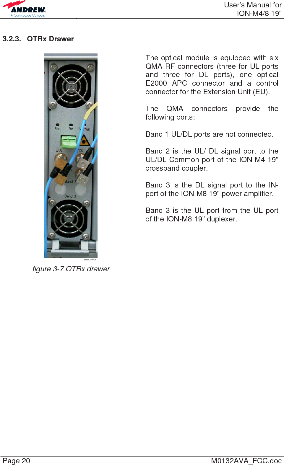
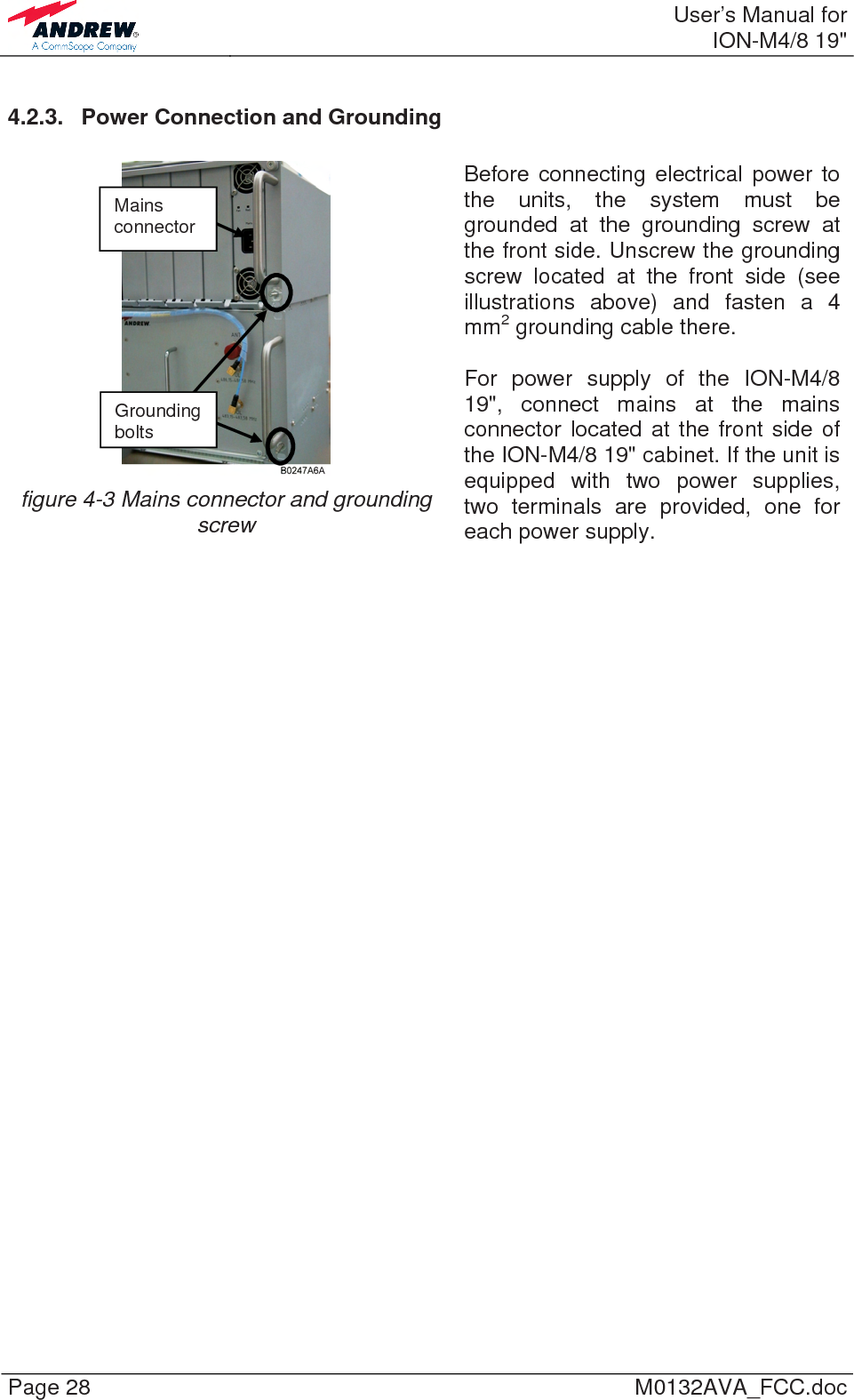
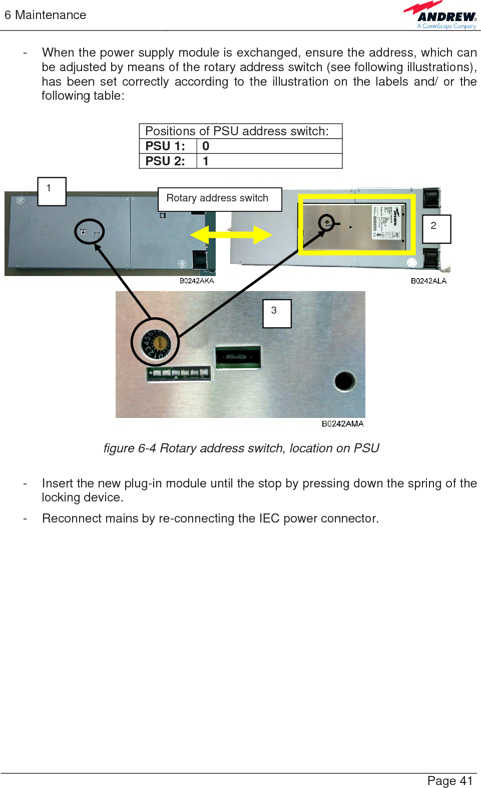
![3 Functional Description Page 23 3.2.6. PSU Drawer The power supply module is equipped with an IEC power connector for mains supply and a Status alarm LED. Always disconnect the mains connector switch the PSU module off before removing it! The Status LED shows a green light during normal error-free operation. The Status LED shows a red light when there is a power-supply failure. The Fan LED shows a red light when a fan alarm is raised due to a fan failure. The Red. [Redundany mode] LED shows green light if redundancy mode is configured. It never shows a red light. figure 3-10 PSU drawer figure 3-11 I2C switch located on the PSU board Positions possible of I2C bus switch: Non-redundant configuration Redundant configuration 1 RU & 1 EU in 1 subrack 2 RUs in 1 subrack 2 RUs in 2 subracks A = Main RU A = RU 1 A = Main RU B = EU or B = RU 2 or B = Substitute RU table 3-2 I2C bus switch on PSU module, rear side I2C bus switch Red. mode Status Fan 1. 2. Mains connector – DISCONNECT!](https://usermanual.wiki/Andrew-Wireless-System/IONM4819I/User-Guide-1239807-Page-23.png)