Andrew Wireless System IONM4819I ION-M4/8 19" RF Repeater User Manual M0132AVA FCC
Andrew Wireless System ION-M4/8 19" RF Repeater M0132AVA FCC
Users Manual
ION-M4/8 19"
Optical
Remote Unit
User's Manual
M0132AVA

User’s Manual for
ION-M4/8 19"
Page 2 M0132AVA_FCC.doc
© Copyright 2009 CommScope, Inc.
All rights reserved.
Andrew Solutions is a trademark of CommScope, Inc.
All information contained in this manual has been revised thoroughly. Yet Andrew
Solutions accepts no liability for any omissions or faults.
Andrew Solutions reserves the right to change all hard- and software characteristics
without notice.
Names of products mentioned herein are used for identification purposes only and
may be trademarks and / or registered trademarks of their respective companies.
No parts of this publication may be reproduced, stored in a retrieval system,
transmitted in any form or by any means, electronical, mechanical photocopying,
recording or otherwise, without prior written permission of the publisher.
Andrew Wireless Systems GmbH, 02-November-2009

Page 3
TABLE OF CONTENTS
1. GENERAL 7
1.1. USED ABBREVIATIONS 7
1.2. HEALTH AND SAFETY WARNINGS 9
1.3. ABOUT ANDREW SOLUTIONS 10
1.4. INTERNATIONAL CONTACT ADDRESSES FOR WIG CUSTOMER SUPPORT 11
2. INTRODUCTION 13
2.1. PURPOSE 13
2.2. THE ION-M4/8 19" RU - RF COVERAGE FOR 400 / 800 MHZ NETWORKS 13
3. FUNCTIONAL DESCRIPTION 15
3.1. GENERAL 15
3.2. COMPONENTS OF THE ION-M4/8 19" REMOTE UNIT 16
3.2.1. Main Subrack 19" 17
3.2.2. Alarm Board 18
3.2.3. OTRx Drawer 20
3.2.4. Crossband-Coupler Drawer of ION-M4 19" 21
3.2.5. Amplifier Drawers 470-512 MHz and 851-894 MHz 21
3.2.6. PSU Drawer 23
3.2.7. Duplexer Subrack 24
4. COMMISSIONING 25
4.1. MECHANICAL INSTALLATION – GENERAL 25
4.2. ELECTRICAL INSTALLATION 26
4.2.1. General 26
4.2.2. Cabling and Connections 27
4.2.3. Power Connection and Grounding 28
4.3. CONNECTION OF THE ANTENNA CABLES 29
4.4. OPTICAL-FIBRE-CABLE CONNECTION – RULES 29
4.5. AUTO-LEVELLING 30
4.6. COMMISSIONING 31

User’s Manual for
ION-M4/8 19"
Page 4 M0132AVA_FCC.doc
5. ALARMS 35
5.1. BITE AND ALARMS 35
5.2. HANDLING OF ALARMS 35
5.3. ALARM STATUS 35
5.4. TROUBLESHOOTING 35
5.5. STATUS LED ALARMS 35
6. MAINTENANCE 37
6.1. GENERAL 37
6.2. REPLACEMENT OF COMPONENTS 38
6.2.1. Replacement of Amplifier and Optical Plug-in Modules 38
6.2.2. Replacement of Power Supply Plug-in Modules 40
7. APPENDIX 43
7.1. LAYOUT 43
7.2. SPECIFICATIONS 45
7.2.1. Electrical Specifications 45
7.2.2. Mechanical Specifications 47
7.2.3. Environmental and Safety Specifications 47
7.3. SPARE PARTS 48
8. INDEX 49

Page 5
FIGURES AND TABLES
figure 3-1 Configuration of an ION-M4/8 19" RU ...................................................... 15
figure 3-2 ION-M4/8 19", layout of front side ............................................................ 16
figure 3-3 Main Subrack 19" ION-M4 19", front side................................................. 17
figure 3-4 Main Subrack 19'', seals on rear side....................................................... 17
figure 3-5 Alarm board for RU................................................................................... 19
figure 3-6 Alarm board for EU................................................................................... 19
figure 3-7 OTRx drawer ............................................................................................ 20
figure 3-8 Alarm triggering ........................................................................................ 21
figure 3-9 I2C switch located on the amplifier board ................................................. 22
figure 3-10 PSU drawer ............................................................................................ 23
figure 3-11 I2C switch located on the PSU board...................................................... 23
figure 3-12 Duplexer subrack of ION-M4 19"............................................................ 24
figure 4-1 ION-M4/8 19" cabling on front side........................................................... 27
figure 4-2 ION-M4/8 19" connectors on front side..................................................... 27
figure 4-3 Mains connector and grounding screw..................................................... 28
figure 5-1 Alarm triggering ........................................................................................ 36
figure 6-1 OTRx and amplifier modules, locking device............................................ 38
figure 6-2 Rotary address switch, location on PA ..................................................... 39
figure 6-3 PSU module, locking device..................................................................... 40
figure 6-4 Rotary address switch, location on PSU................................................... 41
figure 7-1 Layout of the ION-M4 19" remote unit, front side ..................................... 43
figure 7-2 Layout of the ION-M4 19" remote unit, rear side ...................................... 43
figure 7-3 Cabinet drawing........................................................................................ 44
table 1-1 List of international contact addresses....................................................... 12
table 3-1 I2C bus switch on amplifier module, rear side............................................ 22
table 3-2 I2C bus switch on PSU module, rear side .................................................. 23
table 5-1 Status LED alarm coding........................................................................... 36

User’s Manual for
ION-M4/8 19"
Page 6 M0132AVA_FCC.doc
For your notes:

1 General
Page 7
1. GENERAL
1.1. USED ABBREVIATIONS
3GPP 3rd Generation Partnership Project
ALC Automatic Level Control
AMPS American Mobile Phone System or Advanced Mobile Phone System
APAC Automatic Power Adjustment Circuit
BCCH Broadcast Control Channel
BITE Built-In Test Equipment
BTS Base Transceiver Station
CBC Crossband Coupler
CDMA Code Division Multiple Access
CEPT Conférénce Européenne des Postes et Télécommunications
CF Center Frequency
CFO Center Frequency Offset
DL Downlink
EDGE Enhanced Data Rates for GSM Evolution
ESD Electrostatic Discharge
ETACS Enhanced TACS
ETS European Telecommunication Standard
ETSI European Telecommunication Standards Institute
FSK Frequency Shift Keying
GSM Global System for Mobile Communication
I2C-Bus Inter-Integrated Circuit Bus (Philips)
ID No Identification Number
IF Intermediate Frequency
LAN Local Area Network
LED Light Emitting Diode
LMT Local Maintenance Terminal
LNA Low Noise Amplifier
MCC Mobile Country Code
MNC Mobile Network Code
MOR Microwave Optical Repeater
MR Microwave Repeater
MS Mobile Station
MTBF Mean Time Between Failure
OIP-3 Output Intercept Point of the 3rd order
OMC Operation and Maintenance Center
OTRx Optical Transceiver
PA Power Amplifier
PCMCIA Personal Computer Modem Communication International Association
PCS Personal Communication System
PSTN Public Switched Telephone Network
PSU Power Supply Unit
Rev Revision
RF Radio Frequency
RLP Radio Link Protocol

User’s Manual for
ION-M4/8 19"
Page 8 M0132AVA_FCC.doc
RSSI Receive Signal Strength Indication
RTC Real-Time Clock
RX Receiver
SCL Serial Clock
SDA Serial Data
SMSC Short Message Service Center
TACS Total Access Communication System
TCH Traffic Channel
TDMA Time Division Multiple Access
TX Transmitter
UE User Equipment
UL Uplink
UMTS Universal Mobile Telecommunication System
UPS Uninterruptable Power Supply
URL Uniform Resourece Loctor
VSWR Voltage Standing Wave Ratio
WCDMA Wide Code Division Multiple Access
WIG Wirless Innovations Group

1 General
Page 9
1.2. HEALTH AND SAFETY WARNINGS
1. Only suitably qualified personnel is allowed to work on this unit and only after becoming
familiar with all safety notices, installation, operation and maintenance procedures
contained in this manual.
2. Read and obey all the warning labels attached to the unit. Make sure that the warning
labels are kept in a legible condition and replace any missing or damaged labels.
3. Obey all general and regional installation and safety regulations relating to work on high
voltage installations, as well as regulations covering correct use of tools and personal
protective equipment.
4. Keep operating instructions within easy reach and make them available to all users.
5. It is the responsibility of the network provider to implement prevention measures to avoid
health hazards which may be associated to radiation from the antenna(s) connected to
the unit.
6. The antennas of the repeater (integrated and / or external) have to be installed in a way
that the regional and national RF exposure compliance requirements are met.
7. Make sure access is restricted to qualified personnel.
8. Only licence holders for the respective frequency range are allowed to operate this unit.
9. Use this equipment only for the purpose specified by the manufacturer. Do not carry out
any modifications or fit any spare parts which are not sold or recommended by the
manufacturer. This could cause fires, electric shock or other injuries.
10. Before opening the unit, disconnect mains.
11. ESD precautions must be observed! Before commencing maintenance work, use the
available grounding system to connect ESD protection measures.
12. This unit complies with European standard EN60950.
13. IMPORTANT NOTE: To comply with FCC RF exposure compliance requirements, the
following antenna installation and device operating configurations must be satisfied: A
separation distance of at least 20 cm must be maintained between the antenna of this
device and all persons. RF exposure compliance may need to be addressed at the time
of licensing, as required by the responsible FCC Bureau(s), including antenna co-location
requirements of 1.1307(b)(3). Maximum permissible antenna gain is 12 dBi.
14. Make sure the repeater settings are according to the intended use (see also product
information of the manufacturer) and regulatory requirements are met.
15. Although the repeater is internally protected against overvoltage, it is strongly
recommended to earth the antenna cables close to the antenna connectors of the
repeater for protection against atmospheric discharge.

User’s Manual for
ION-M4/8 19"
Page 10 M0132AVA_FCC.doc
1.3. ABOUT ANDREW SOLUTIONS
Andrew Wireless Systems GmbH based in Buchdorf/ Germany, is a leading
manufacturer of coverage equipment for mobile radio networks, specializing in low
cost, high performance, RF and optical repeaters. Our optical distributed networks
and RF repeater systems provide coverage for every application: outdoor use, indoor
installations, tunnels, subways and many more.
Andrew Wireless Systems GmbH belongs to the Wireless Innovations Group (WIG).
Being a part of Andrew Solutions, WIG has unparalleled experience in providing RF
coverage and capacity solution for wireless networks in both indoor and outdoor
environment.
Andrew Solutions, a CommScope Company, is the foremost supplier of one-stop,
end-to-end radio frequency (RF) solutions. Our products are complete solutions for
wireless infrastructure from top-of-the-tower base station antennas to cable systems
and cabinets, RF site solutions, signal distribution, and network optimization.
Andrew Solutions has global engineering and manufacturing facilities. In addition, it
maintains field engineering offices throughout the world.
We operate a quality management system in compliance with the requirements of
ISO 9001. All equipment is manufactured using highly reliable material. In order to
ensure constant first-rate quality of the products, comprehensive quality monitoring is
conducted at all fabrication stages. Finished products leave the factory only after a
thorough final acceptance test, accompanied by a test certificate guaranteeing
optimal operation.
The declaration of conformity for the product is available upon request from the local
sales offices or from Andrew Solutions directly.
To make the utmost from this unit, we recommend you carefully read the instructions
in this manual and commission the unit only according to these instructions.
For technical assistance and support, contact the local office or Andrew Solutions
directly at one of the following addresses listed in the next chapter.

1 General
Page 11
1.4. INTERNATIONAL CONTACT ADDRESSES FOR WIG CUSTOMER
SUPPORT
Wireless Innovations Group (WIG)
Americas:
Canada United States
Andrew Solutions Canada Andrew Solutions,
Andrew LLC, A CommScope Company
Mail 620 North Greenfield Parkway
Garner, NC 27529
U.S.A. Mail 620 North Greenfield Parkway
Garner, NC 27529
U.S.A.
Phone +1-905-878-3457 (Office)
+1 416-721-5058 (Mobile) Phone +1-888-297-6433
Fax +1-905-878-3297 Fax +1-919-329-8950
E-mail Peter.Masih@andrew.com
WIsupport.us@andrew.com
E-mail WIsupport.us@andrew.com
Brazil & South America Mexico, Central America &
Caribbean region
Andrew Solutions,
A CommScope Company Andrew Solutions Mexico
Mail
Av. Com. Camilo Julio 1256
Predio B
Zonal Industrial CP 597
Sorocaba SP 18086-000
Brazil
Mail
Monte Elbruz 124-402A
Col. Palmas Polanco 11560
Mexico, D.F.
Mexico
Phone + 55-15-9104-7722 Phone + 52-55-1346-1900 (Office)
+52-1-55-5419-5260 (Mobile ).
Fax + 55-15-2102-4001 Fax +52-55-1346-1901
E-mail WIsupport@andrew.com
E-mail WIsupport@andrew.com
APAC Countries:
China Australia
Andrew Solutions Hong Kong Andrew Corporation (Australia)
LLC Pty Ltd.
Mail
Room 915
Chevalier Commercial Centre
8 Wang Hoi Rd
Kowloon Bay SAR
Hong Kong
Mail
Unit 1
153 Barry Road
Campbellfield
VIC 3061
Australia
Phone +852-310-661-00 Phone +613-9300-7969
Fax +852-2751-7800 Fax +613-9357-9110
E-mail WISupport.china@andrew.com
E-mail WIsupport.australia@andrew.com

User’s Manual for
ION-M4/8 19"
Page 12 M0132AVA_FCC.doc
Europe:
United Kingdom France
Andrew Solutions UK Ltd Andrew Solutions France
Mail
Unit 15, Ilex House
Mulberry Business Park
Fishponds Road
Wokingham Berkshire
RG41 2GY
England
Mail
28, Rue Fresnel
Z.A Pariwest
BP 182
78313 Coignières Cedex
France
Phone +44-1189-366-792 Phone +33 1 30 05 45 50
Fax +44-1189-366-773 Fax +33 1 34 61 13 74
E-mail WIsupport.uk@andrew.com
E-mail WIsupport@andrew.com
Germany Czech Republic
Andrew Wireless Systems GmbH Andrew Solutions Czech Republic
C-Com, spol. s r.o
Mail Industriering 10
86675 Buchdorf
Germany Mail U Moruší 888
53006 Pardubice
Czech Republic
Phone +49-9099-69-0 Phone +420-464-6280-80
Fax +49-9099-69-930 Fax +420-464-6280-94
E-mail WIsupport@andrew.com
E-mail WIsupport@andrew.com
Austria Switzerland
Andrew Wireless Systems (Austria)
GmbH Andrew Wireless Systems AG
Mail Weglgasse 10
Wien-Schwechat 2320
Austria Mail Tiergartenweg 1
CH-4710 Balsthal
Switzerland
Phone +43-1706-39-99-10 Phone +41-62-386-1260
Fax +43-1706-39-99-9 Fax +41-62-386-1261
E-mail WIsupport.austria@andrew.com
E-mail support.ch@andrew.com
Italy Spain & Portugal
Andrew Wireless Systems S.r.l., Faenza,
Italy Andrew Solutions España S.A.
Mail Via de Crescenzi 40
Faenza 48018
Italy Mail C/ Salvatierra, 5 - 3a pt.
28034 Madrid
Spain
Phone +39-0546-697111 Phone +34-91-745-20 40
Fax +39-0546-682768 Fax +34-91-564-29 85
E-mail WIsupport.italia@andrew.com
E-mail WIsupport.iberia@andrew.com
table 1-1 List of international contact addresses

2 Introduction
Page 13
2. INTRODUCTION
2.1. PURPOSE
Cellular telephone systems transmit signals in two directions between base
transceiver station (BTS) and mobile stations (MS) within the signal coverage area.
If weak signal transmissions occur within the coverage area because of indoor
applications, topological conditions or distance from the transmitter, extension of the
transmission range can be achieved by means of an optical distribution system.
Such a system contains an optical master unit and several remote units. The number
of the remote units depends on the hardware and software configuration. The remote
units are connected to the master unit with optical links. The optical loss must be less
than 10 dB inclusive optical couplers or splitters.
The master unit is the connection to the base transceiver stations. The configuration
of a master unit depends on the number of the remote units and the frequency range.
The optical transmission uses Wavelength Division Multiplex (WDM) systems with a
wavelength of 1550 nm in the uplink and 1310 nm in the downlink.
2.2. THE ION-M4/8 19" RU - RF COVERAGE FOR 400 / 800 MHZ NETWORKS
Andrew’s ION-M4/8 19" is a robust, intelligent optical RU to meet designer’s
requirements for high reliability with various redundancy and extension options.
The ION-M4/8 19" is a multi-band, multi-carrier optical RU. It is used in conjunction
with a MU in the ION-M optical distribution system.
This system transports a Tetra, Tetrapol, CDMA or any other signal within up to 4
frequency bands in 400 MHz and the entire 800 MHz IDEN band while providing a
cost-effective solution to distribute capacity from a cluster of base stations.
The ION-M optical distribution system is a cost-efficient coverage solution for dense
urban areas, tunnels, subways, railways, roadways, airports, convention centres, and
other locations where physical structures increase path loss.

User’s Manual for
ION-M4/8 19"
Page 14 M0132AVA_FCC.doc
The ION-M4/8 19" has been specifically designed to reduce zoning problems. The
compact mechanical housing is designed to mount alongside structures in such a
way that it has minimal visual impact.
The ION-M can be easily set-up and supervised by a graphical user interface (GUI).
An auto-levelling function compensates for the optical link loss and making
installation easy and quick. The entire system can be monitored remotely by
A.I.M.O.S., the Andrew OMC. The Andrew OMC uses SNMP protocol and is
compliant to X.733 standard. Should a sophisticated management interface not be
required, the MU can be directly connected to the alarm interface of a base station
via relay contacts.
Features:
• Efficient, high power amplifier
• WDM for uplink/downlink to multiple RUs on a single fibre
• Star and daisy chain configuration
• Redundancy and extension options available
• Complete operations and management system for configuration and alarming
• OMC with SNMP according to X.733 standard available
• Easy commissioning by means of auto-setup and auto-levelling
3 Functional Description
Page 15
3. FUNCTIONAL DESCRIPTION
3.1. GENERAL
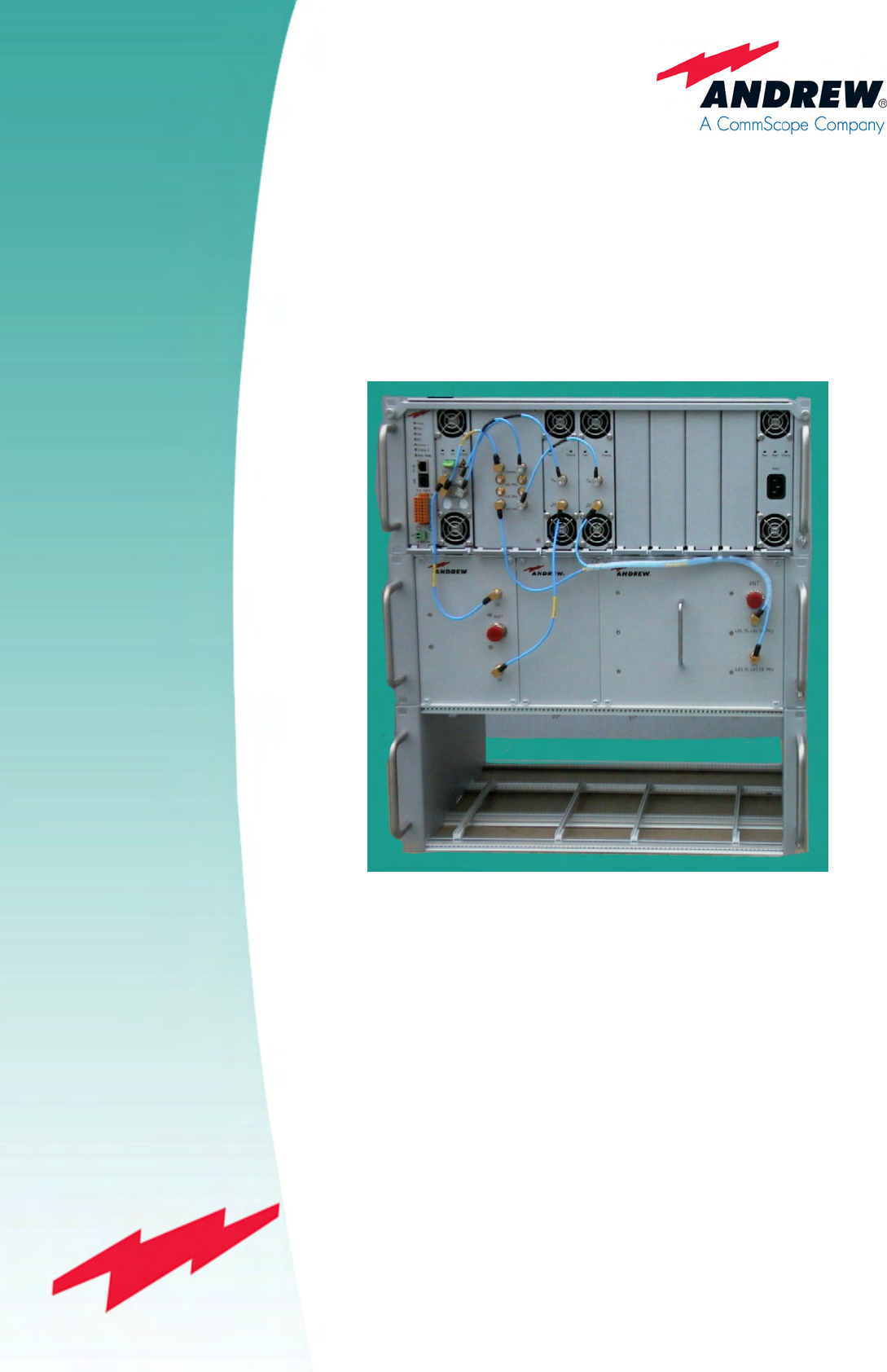
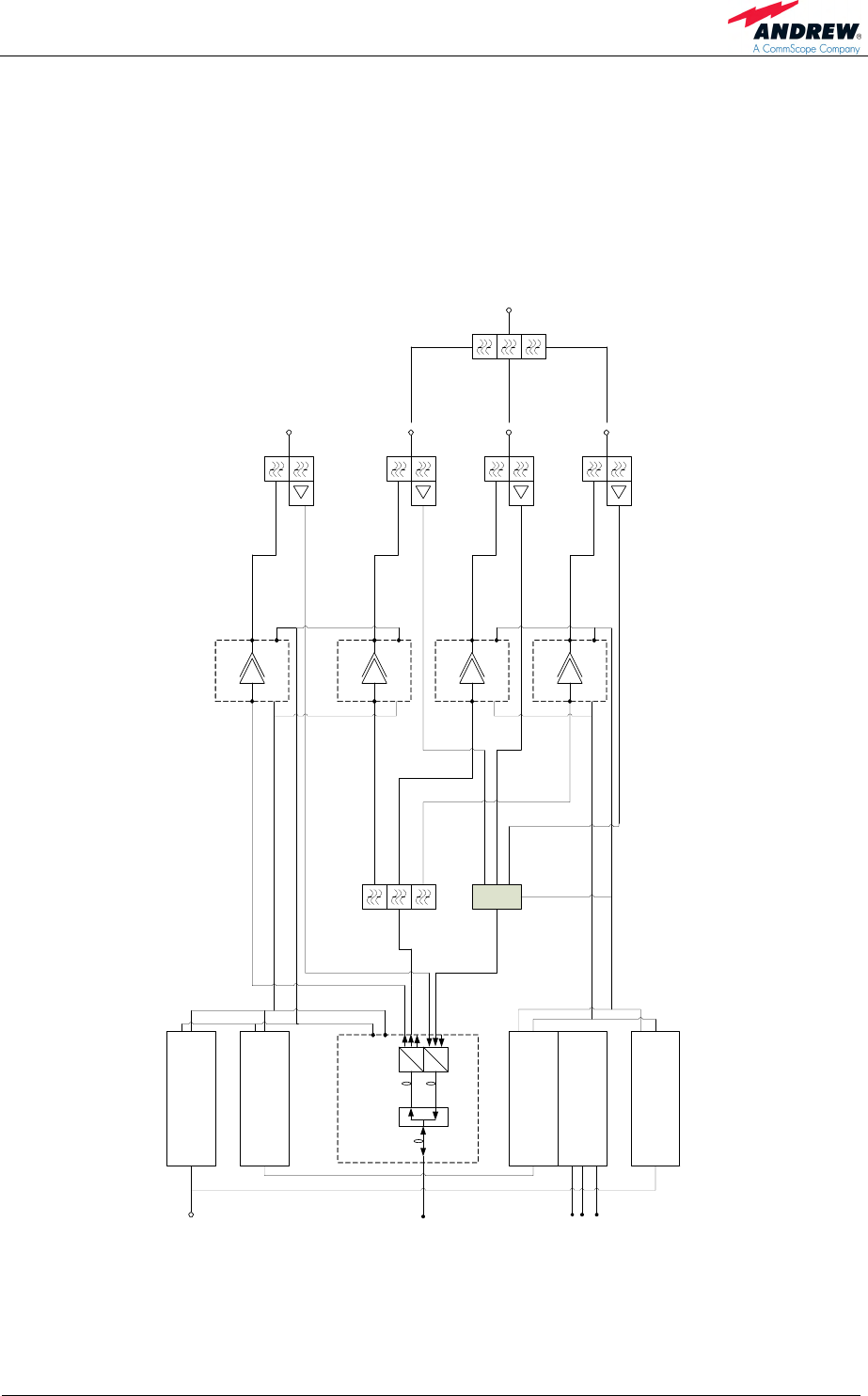
The following figure shows the configuration of an ION-M4/8 19" RU:
o
e
o
e
DL
UL
UL/DL
WDM OTRX
from / to Master Unit
Optical Module OTRx 1/4/9
RU-LS +32 VDC
I²C
350 – 512 MHz
67 – 174 MHz
716 – 960 MHz
350 – 512 MHz
67 – 174 MHz
698 – 915 MHz
1:3
Power Amplifier 1
Fin. Ampl.
851-894 MHz
+28 VDCI²C
Power Amplifier 2
Fin.Ampl. 45W
851-894
+28 VDCI²C
Power Amplifier 3
Fin. Ampl.
450-490 MHz
+28 VDCI²C
Power Amplifier 4
Fin. Ampl.
450-490 MHz
+28 VDCI²C
Control Unit
RCM161-C LT
PSU 1
AC IN 100-240 V
Control Unit EU
RCM161-C LT
19" Alarm Board EU
with RCM
PSU 2
AC IN 100-240 V
Mains
RS485
+32 VDC
I²C
Crossband coupler
with DC bypass
Act. Combiner
With DC supply
ANT
ANT
Duplexer
DL 851-869MHz
UL 806-824MHz
Duplexer
DL 460.1625-462.9875MHz
UL 465.1625-467.9875MHz
ID 7602995-00
Duplexer
DL 470.775-471.000 MHz
UL 473.775-474.000 MHz
Duplexer
DL 483.150-483.575 MHz
UL 486.150-486.575 MHz
Ext. Al in
Ext. Al out
32V
E3189B0B
Main (I2C bus A)
Extension (I2C bus B)
I²C 0x010
(10 Bit)
„0"
I²C
figure 3-1 Configuration of an ION-M4/8 19" RU
User’s Manual for
ION-M4/8 19"
Page 16 M0132AVA_FCC.doc
3.2. COMPONENTS OF THE ION-M4/8 19" REMOTE UNIT
The actual configuration of the remote unit can be seen at the configuration list which
is part of the delivery.
The following figure shows an exemplary view of an ION-M4/8 19" remote unit to
illustrate the individual components.
figure 3-2 ION-M4/8 19", layout of front side
Module
clamps
Duplexer subrack
for upgrade
Duplexer
400 MHz
Duplexer
800 MHz
A
larm card OTRx CBC PA 800 MHz PA 400 MHz PSU
3 Functional Description
Page 17
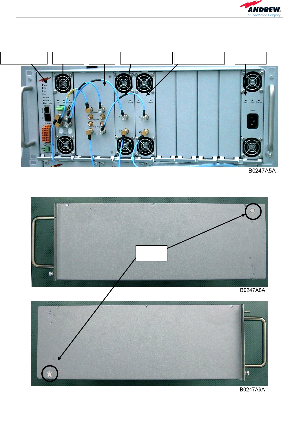
3.2.1. Main Subrack 19"
figure 3-3 Main Subrack 19" ION-M4 19", front side
figure 3-4 Main Subrack 19'', seals on rear side
A
larm card OTRx CBC PA 800 MHz PA 400 MHz PSU
Seals

User’s Manual for
ION-M4/8 19"
Page 18 M0132AVA_FCC.doc
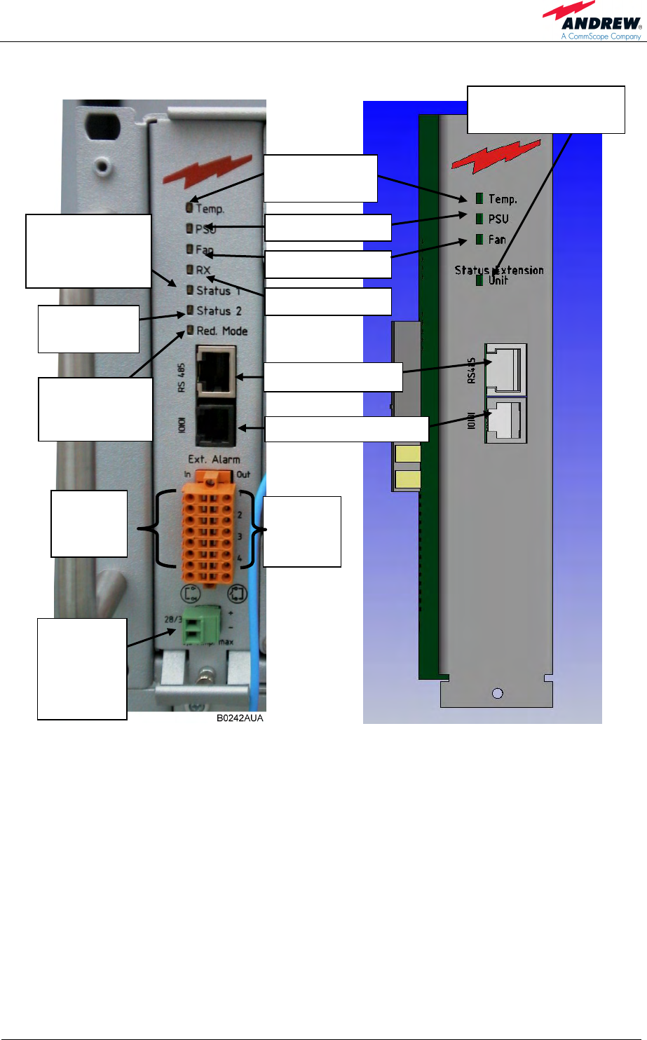
3.2.2. Alarm Board
The remote unit alarm board provides 4 alarm inputs for supervision of external
devices, 4 configurable alarm outputs for simple alarm forwarding and 7 alarm LEDs
(for the RU) or 4 alarm LEDs (for the EU). The Status alarm LEDs are green in
normal operation, red when there is an alarm concerning the RU and yellow when
the alarm cause is probably outside the unit, e. g. in case of a fibre-optic RX alarm.
The other alarm LEDs are green if the concerned module is in normal operation and
red if the module has an alarm.
Status 1 LED = summary alarm LED
1.) for 2 RUs in 1 subrack: Status 1 LED shows the status of the first RU
2.) for 1 RU & 1 EU in 1 subrack: Status 1 LED shows the status of the RU
3.) for 1 RU in 1 subrack: Status 1 LED shows the status of the RU
Status 2 LED = depending on which unit the alarm is raised.
1.) for 2 RUs in 1 subrack: Status 2 LED shows the status of the second RU
2.) for 1 RU & 1 EU in 1 subrack: Status 2 LED shows the status of the EU
3.) for 1 RU in 1 subrack: Status 2 LED shows any LED => no function
3 Functional Description
Page 19
Note: This type of alarm board is only
installed in the Extension Unit.
figure 3-5 Alarm board for RU figure 3-6 Alarm board for EU
For detailed information on the Status LED please refer to chapter 5.5 Status LED
Alarms.
Status LED for EU=>
summary alarm LED
External
alarm
outputs
External
alarm
inputs
Temperature
alarm LED
PSU alarm LED
Redundant
PSU Mode
alarm LED
Fan alarm LED
Status 2
alarm LED
Status 1
alarm LED for
RU =>summary
alarm LED
RS232 local interface
28 V or
32 V
connector
depending
on PSU
Rx alarm LED
RS485 interface
User’s Manual for
ION-M4/8 19"
Page 20 M0132AVA_FCC.doc
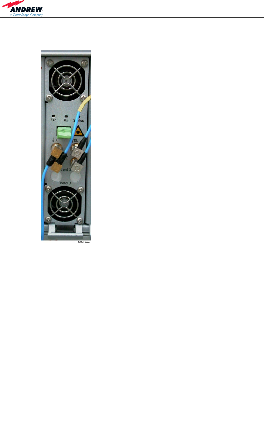
3.2.3. OTRx Drawer
figure 3-7 OTRx drawer
The optical module is equipped with six
QMA RF connectors (three for UL ports
and three for DL ports), one optical
E2000 APC connector and a control
connector for the Extension Unit (EU).
The QMA connectors provide the
following ports:
Band 1 UL/DL ports are not connected.
Band 2 is the UL/ DL signal port to the
UL/DL Common port of the ION-M4 19"
crossband coupler.
Band 3 is the DL signal port to the IN-
port of the ION-M8 19" power amplifier.
Band 3 is the UL port from the UL port
of the ION-M8 19" duplexer.
3 Functional Description
Page 21
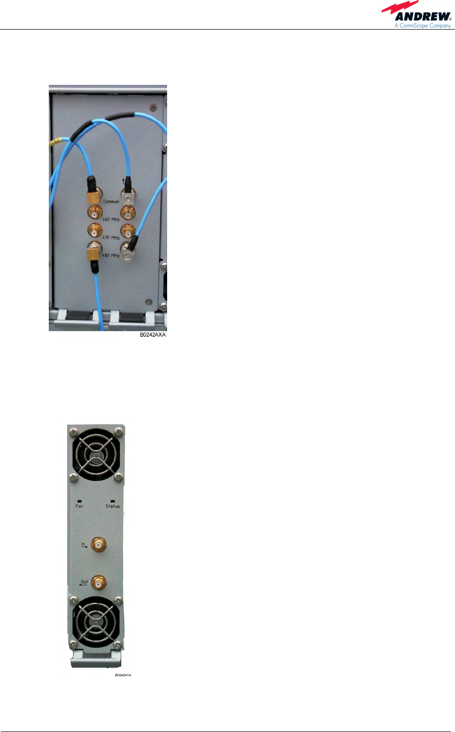
3.2.4. Crossband-Coupler Drawer of ION-M4 19"
figure 3-8 Alarm triggering
The crossband-coupler (CBC) module is
equipped with 8 QMA RF connectors –
(three for DL ports and three for UL ports.
These are the Common port from/to OTRx,
DL Low Band / Middle Band/ High Band to
power amplifiers, UL Low Band/ Middle
Band/ High Band from the duplexer.
3.2.5. Amplifier Drawers 470-512 MHz and 851-894 MHz
Each amplifier module provides two QMA RF
ports. The upper RF IN port connects to the
crossband-coupler port of the ION-M4 19'', the
lower RF OUT port to the corresponding DL
and/ or UL port of the corresponding duplexer.
For ION-M8 19'', the RF cable comes directly
from the OTRx.
Max. of up to 3 PAs in 400 MHz range can be
equipped in the ION-M 4/8 19".
figure 3 7 Amplifier drawer
User’s Manual for
ION-M4/8 19"
Page 22 M0132AVA_FCC.doc
figure 3-9 I2C switch located on the amplifier board
Positions possible of I2C bus switch:
Non-redundant
configuration Redundant configuration
1 RU & 1 EU in 1 subrack 2 RUs in 1 subrack 2 RUs in 2 subracks
A = Main RU A = RU 1 A = Main RU
B = EU or B = RU 2 or B = Substitute RU
table 3-1 I2C bus switch on amplifier module, rear side
I2C bus
switch
3 Functional Description
Page 23
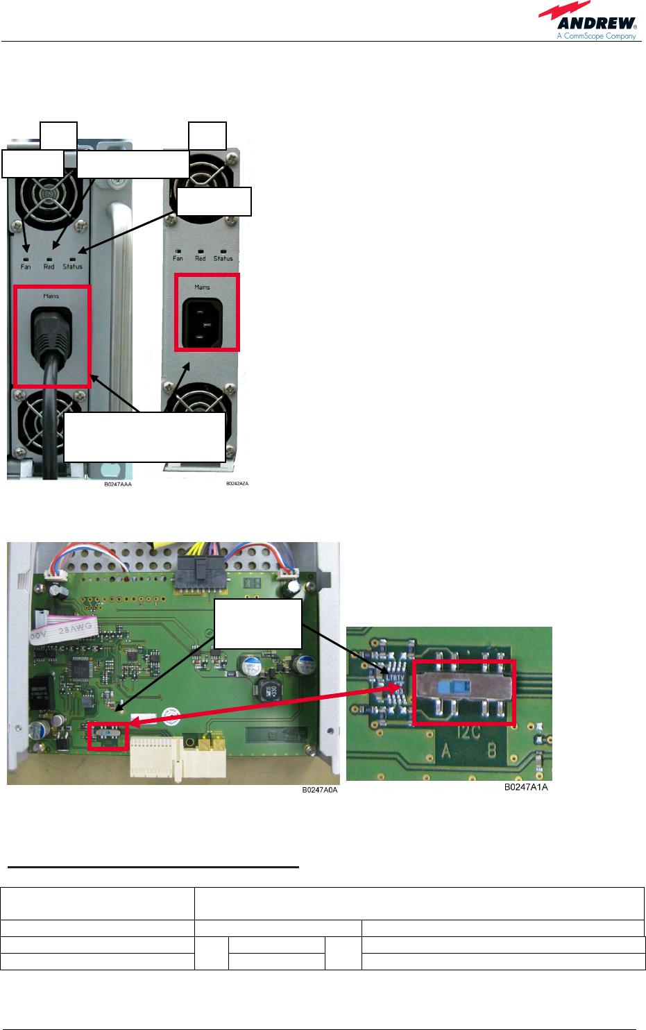
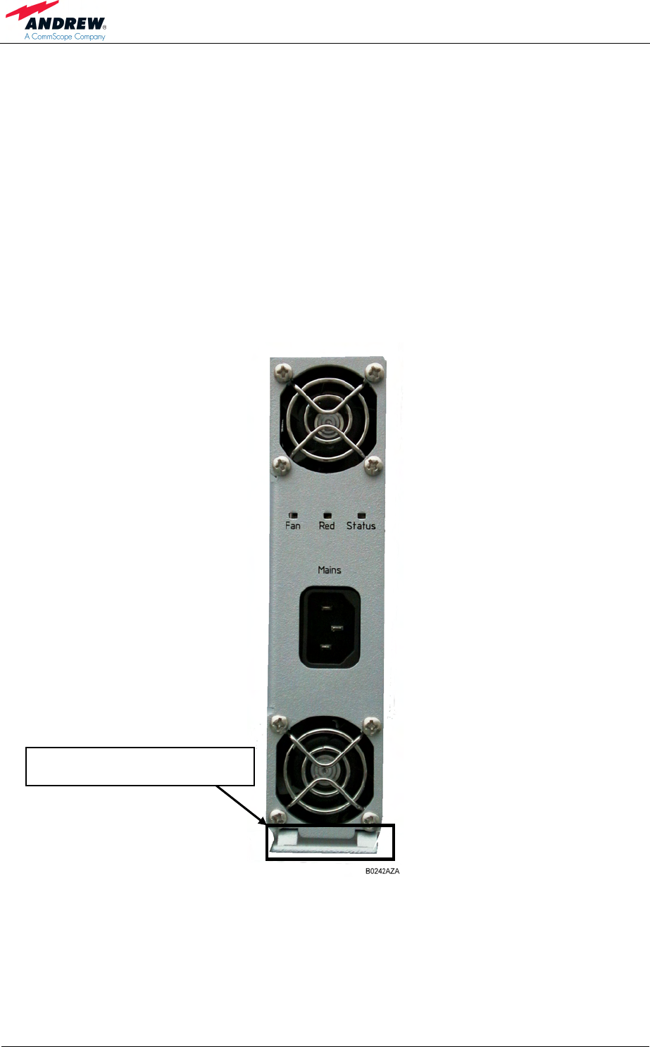
3.2.6. PSU Drawer
The power supply module is equipped with an IEC
power connector for mains supply and a Status
alarm LED.
Always disconnect the mains connector
switch the PSU module off before removing it!
The Status LED shows a green light during
normal error-free operation.
The Status LED shows a red light when there is a
power-supply failure.
The Fan LED shows a red light when a fan alarm
is raised due to a fan failure.
The Red. [Redundany mode] LED shows green
light if redundancy mode is configured. It never
shows a red light.
figure 3-10 PSU drawer
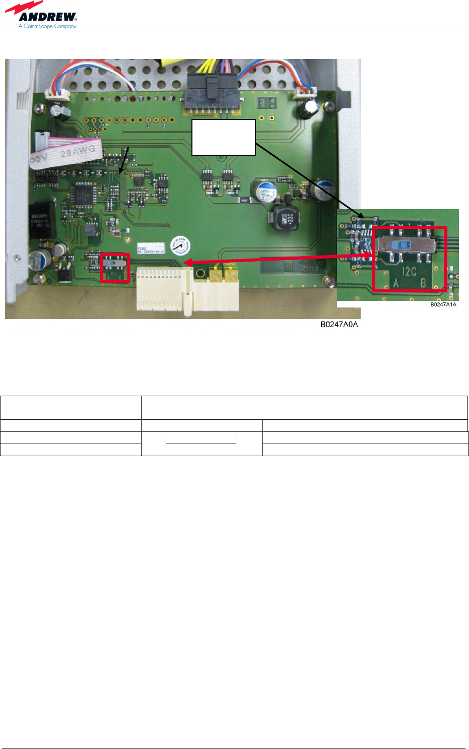
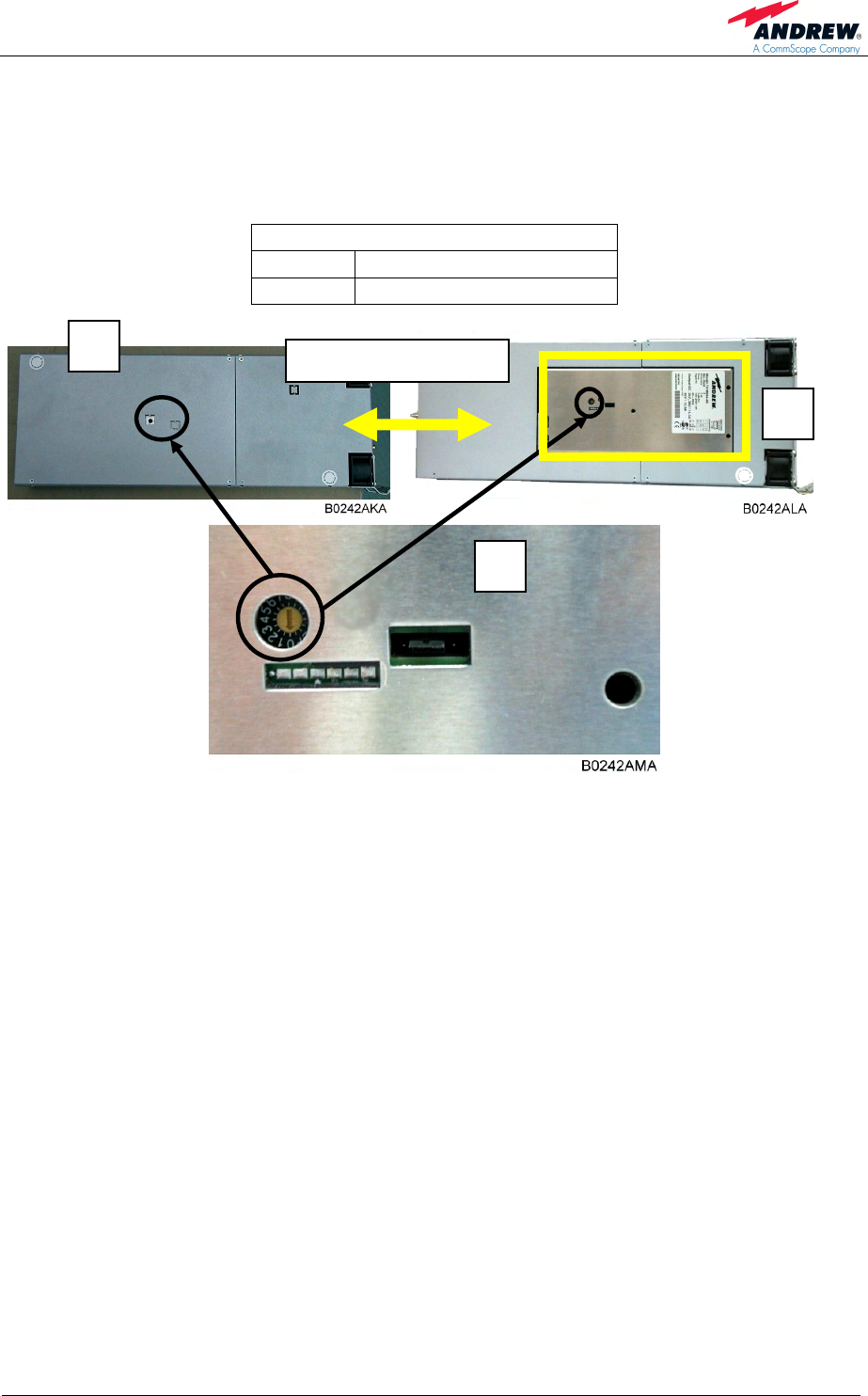
figure 3-11 I2C switch located on the PSU board
Positions possible of I2C bus switch:
Non-redundant
configuration Redundant configuration
1 RU & 1 EU in 1 subrack 2 RUs in 1 subrack 2 RUs in 2 subracks
A = Main RU A = RU 1 A = Main RU
B = EU or B = RU 2 or B = Substitute RU
table 3-2 I2C bus switch on PSU module, rear side
I2C bus
switch
Red. mode
Status
Fan
1. 2.
Mains connector –
DISCONNECT!
User’s Manual for
ION-M4/8 19"
Page 24 M0132AVA_FCC.doc
3.2.7. Duplexer Subrack
The duplexer subrack of the ION-M4/8 19" is available on 2 x 4 HUs.
The duplexer subrack of the 400 MHz band consists of up to 3 duplexers and the
duplexer subrack of the 800 MHz band consists of just 1 duplexer, see following
illustration:
figure 3-12 Duplexer subrack of ION-M4 19"
Each of the two duplexer modules is equipped with one N-female antenna port and
two QMA connectors.
With the duplexer 2 the DL port is connected from the PA 2 OUT-port. The UL port of
duplexer 2 is connected to the High-Band port of the crossband coupler. With the
duplexer 1 the DL port is connected from the PA 1 OUT-port. The UL port of duplexer
1 to the 800 MHz UL-Band port of the OTRx.
Duplexer 2
400 MHz
Duplexer 1
800 MHz
PA 2
400 MHz
PA 1800 MHzOTRx
N-antenna
connectors
CBC
UL port
DL port
UL port
DL port

4 Commissioning
Page 25
4. COMMISSIONING
4.1. MECHANICAL INSTALLATION – GENERAL
Read the health and safety warnings in chapter 1.2 Health and Safety Warnings.
1. Do not install the unit in a way or at a place where the specifications
outlined in the Environmental and Safety Specifications leaflet of the
manufacturer are not met.
2. The unit is designated for 19" rack mounting only.
3. It is recommended only to use the mounting hardware delivered by the
manufacturer. If different mounting hardware is used, the specifications for
stationary use of the remote unit must not be exceeded.
) Note: Exceeding the specified load limits may cause the loss of warranty!
4. The unit is considerably heavy. Ensure there is adequate manpower to
handle the weight of the system (43 kg).
5. Due to high power dissipation the ION-M4/8 19" can reach very high
temperatures. For that reason sufficient airflow must be ensured so that the
outside temperature and the air temperature inside the cabinet on
installation site must not exceed 40 °C. The surface temperature must not
exceed +70 C in any operating condition. Above and below the unit a
minimum distance of 1 HU to other equipment has to be kept. Also observe
the instructions in the individual mounting procedures.
6. Only operate the unit in the 19" rack with door or use additional fan module.
7. For mounting of the unit in a 19" rack, slide rails are required due to the
considerable weight of the unit.
If any different or additional mounting material is used, ensure that the mounting
remains as safe as the mounting designed by the manufacturer. Ensure that the
static and dynamic strengths are adequate for the environmental conditions of the
site. The mounting itself must not vibrate, swing or move in any way that might cause
damage to the remote unit.

User’s Manual for
ION-M4/8 19"
Page 26 M0132AVA_FCC.doc
4.2. ELECTRICAL INSTALLATION
4.2.1. General
Read the health and safety warnings in chapter 1.2 Health and Safety Warnings.
1. This unit contains dangerous voltages. Loss of life, severe personal injury or
property damage can be the result if the instructions contained in this manual are
not followed.
2. It is compulsory to ground the unit before connecting power supply.
3. Although the remote unit is internally protected against over-voltage, it is strongly
recommended to earth the antenna cables close to the antenna connectors of the
remote unit for protection against atmospheric discharge. In areas with strong
lightning it is highly recommended to insert additional lightning protection.
4. If the mains connector of the remote unit is not easily accessible, a disconnect
device in the mains circuit must be provided within easy reach.
5. Before connecting or disconnecting the mains connector at the remote unit,
ensure that mains supply is disconnected.
6. Make sure that an appropriate circuit breaker and an over-current limiting device
are connected between mains and remote unit.
7. A connection of mains supply to a power socket requires the power socket to be
nearby the remote unit.
8. Incorrectly wired connections can destroy electrical and electronic components.
9. To avoid corrosion at the connectors caused by electrochemical processes, the
material of the cable connectors must not cause a higher potential difference than
0.6 V (see electrochemical contact series).
10. It is sufficient to tighten N-antenna connectors hand-screwed. Any use of a tool
(e.g. pair of pliers) might cause damage to the connector and thus lead to
malfunctioning of the remote unit.
11. For unstabilized electric networks which frequently generate spikes, it is advised
to use a voltage limiting device.
12. The unit complies with the surge requirement according to EN 61000-4-5 (fine
protection); however, it is recommended to install an additional medium (via local
supply connection) and/or coarse protection (external surge protection) depending
on the individual application in order to avoid damage caused by over-current.
13. Observe the labels on the front panels before connecting or disconnecting any
cables.
14. Observe that the cable-cross section is 3 x 1.5 mm2 for the voltage feed and
4 mm2 for the grounding bolt.
4 Commissioning
Page 27
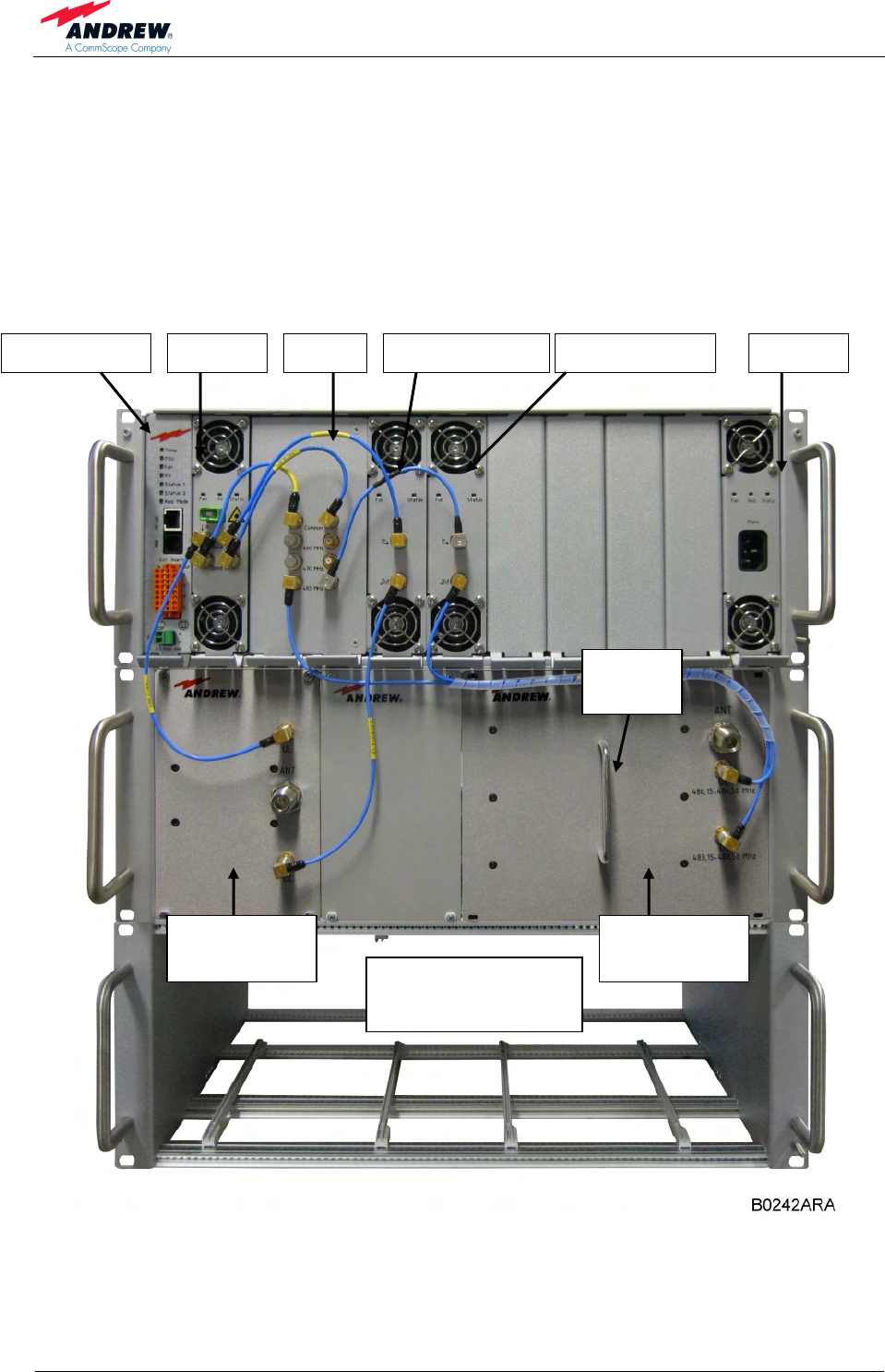
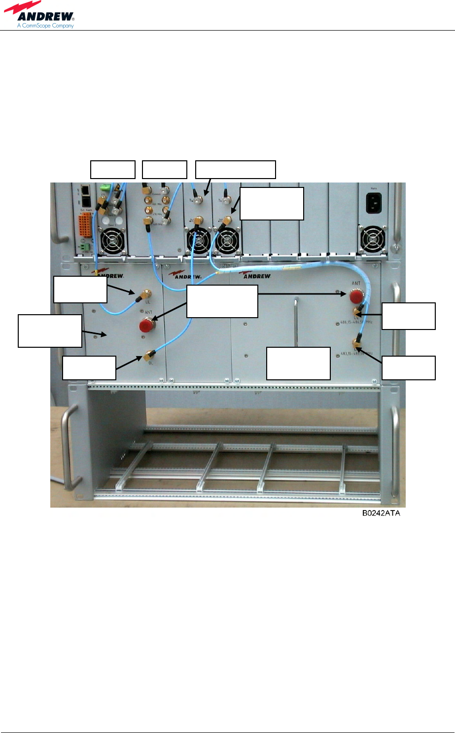
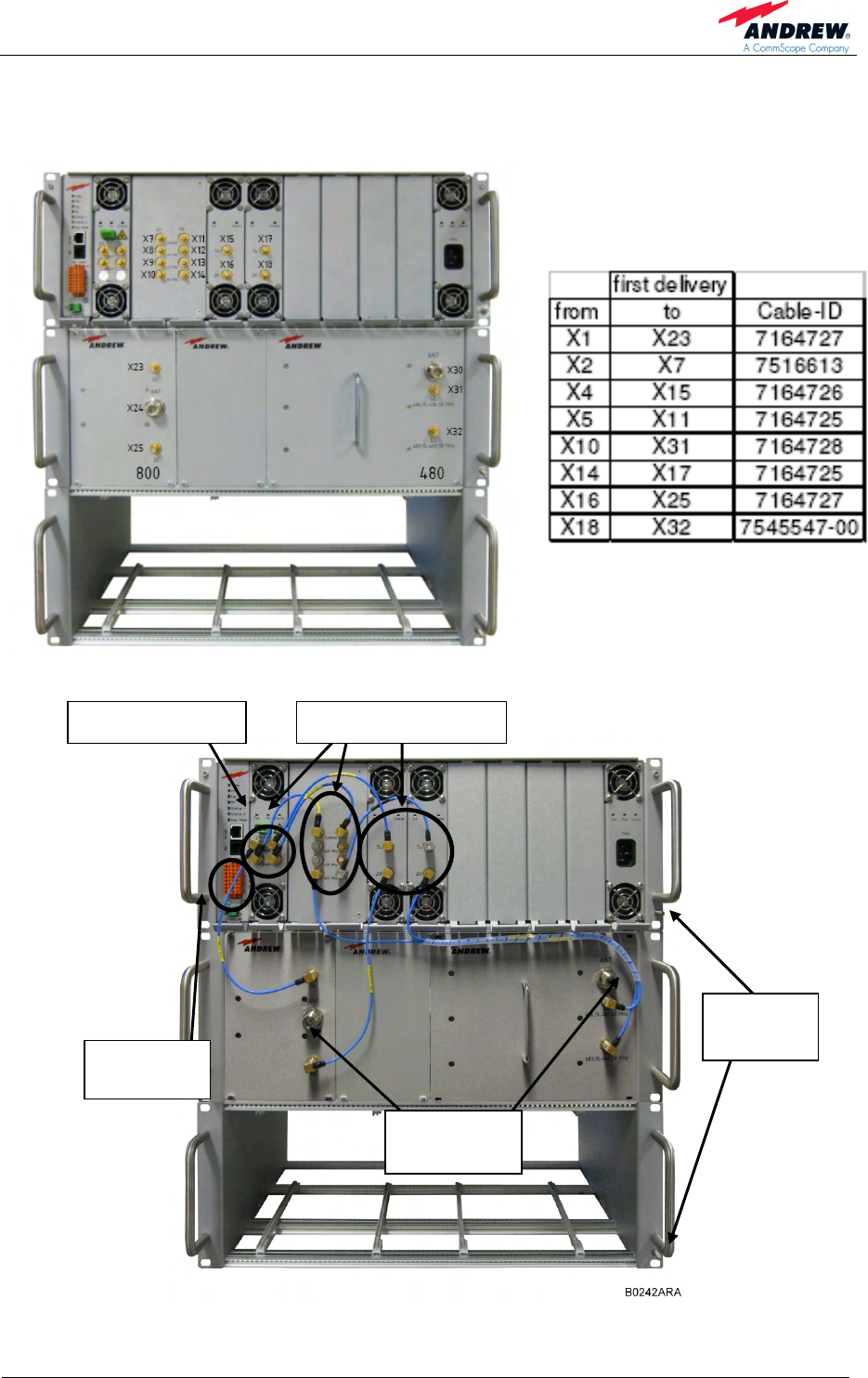
4.2.2. Cabling and Connections
figure 4-1 ION-M4/8 19" cabling on front side
figure 4-2 ION-M4/8 19" connectors on front side
Optical connector
Alarm
connectors
Antenna
connectors
QMA RF connectors
Grounding
bolts
G3189M000
first delivery

User’s Manual for
ION-M4/8 19"
Page 28 M0132AVA_FCC.doc
4.2.3. Power Connection and Grounding
figure 4-3 Mains connector and grounding
screw
Before connecting electrical power to
the units, the system must be
grounded at the grounding screw at
the front side. Unscrew the grounding
screw located at the front side (see
illustrations above) and fasten a 4
mm2 grounding cable there.
For power supply of the ION-M4/8
19", connect mains at the mains
connector located at the front side of
the ION-M4/8 19" cabinet. If the unit is
equipped with two power supplies,
two terminals are provided, one for
each power supply.
Mains
connector
Grounding
bolts

4 Commissioning
Page 29
4.3. CONNECTION OF THE ANTENNA CABLES
The remote unit has N-type antenna connectors. For its location, please refer to
chapter 4.2.2 Cabling and Connections. For mounting the cable connectors, it is
recommended to refer to the corresponding documentation of the connector
manufacturer. The bending radius of the antenna cables must remain within the
given specifications.
For the selection of cable and antenna it should be considered that, on the one hand,
a cable with higher loss is less expensive but, on the other hand, it impairs
performance.
It is sufficient to tighten the N-antenna connectors hand-tight. The use
of a tool (like pliers) may cause damage to the connector and, therefore,
lead to a malfunctioning of the remote unit.
4.4. OPTICAL-FIBRE-CABLE CONNECTION – RULES
Optical signals are transmitted by use of optical fibres. When connecting these fibres
observe the following instructions.
) Note: Care should be taken when connecting and disconnecting
fibre-optic cables. Scratches and dust significantly affect system
performance and may permanently damage the connector. Always
use protective caps on fibre-optic connectors not in use.
In general, optical fibres do not need special protective measures. However,
protection against environmental influences e.g. rodents and humidity must be
considered.
The optical fibre is a single-mode fibre. Type is E9/125 µm with the following
minimum requirements.
Attenuation: <0.36 dB / km @ 1310 nm / <0.26 dB / km @ 1550 nm
Dispersion: <3.5 ps / nm km @ 1310 nm / <18.0 ps / nm km @ 1550 nm
The specified bending radius of the optical fibres must not be exceeded. The pigtails
for the connection between master and remote unit must have a sufficient length. A
protection for the feeding into units must be given.
System attenuation and attenuation of optical components must be determined. This
can be achieved by measuring attenuation and reflection with an appropriate
measuring instrument. For pigtails, a total value of < 0.4 dB (measured to a reference
plug) can be assumed due to the dead zone of the reflectometer. These
measurements must be made with a sufficient length of optical fibre, at the input and
output of the device which has to be measured.

User’s Manual for
ION-M4/8 19"
Page 30 M0132AVA_FCC.doc
Fibre-cable connectors have to be of the same type (E2000APC) as the connectors
used for the unit. The fibre-optic cables are connected to the optical transceiver.
Angled connectors are not compatible with straight optical connectors;
non-compatibility of connectors will result in permanent damage to
both connectors.
Before connecting the fibre cables, follow the procedure below to ensure optimized
performance. It is important for these procedures to be carried out with care:
¾ Remove fibre-optic protective caps.
¾ Do not bend the fibre-optic cable in a tight radius (< 4 cm) as this may cause
cable damage and interrupt transmission.
¾ Using high-grade alcohol and lint-free cotton cleaning swabs, clean the end of
the fibre-optic cable that will be inserted in the optical connectors on the donor
interface box.
¾ Blow out the laser receptacle with clean and dry compressed air to remove
any particulate matter.
¾ Connect the fibre-optic cables by inserting the cable end into the laser
receptacle and aligning the key (on the cable end) with the keyed slot.
¾ Do not use any index matching gels or fluids of any kind in these connectors.
Gels are intended for laboratory use and attract dirt in the field.
4.5. AUTO-LEVELLING
For a proper operation of the auto-levelling function, a defined level has to be set at
the optical interface (DL) of the master unit. The proposed level will be indicated on
the Auot-Levelling-Help on WEB-GUI

4 Commissioning
Page 31
4.6. COMMISSIONING
Read the health and safety warnings in chapter 1.2 Health and Safety Warnings as
well as the description carefully to avoid mistakes and proceed step by step as
described!
• Do not operate the remote unit without terminating the antenna connectors.
The antenna connectors may be terminated by connecting them to their
respective antennas or to a dummy load.
• Only qualified personnel should carry out the electrical, mechanical,
commissioning and maintenance activities that require the unit to be powered
on when open.
• When working on the remote unit do not damage the warranty labels on the
devices. The warranty is void if the seals are broken.
• Ensure that all connections have been performed according to chapter 4.2.2
Cabling and Connections.
User’s Manual for
ION-M4/8 19"
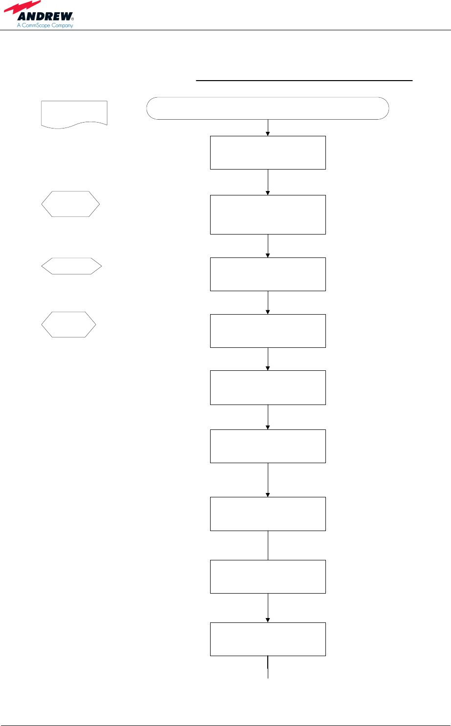
Page 32 M0132AVA_FCC.doc
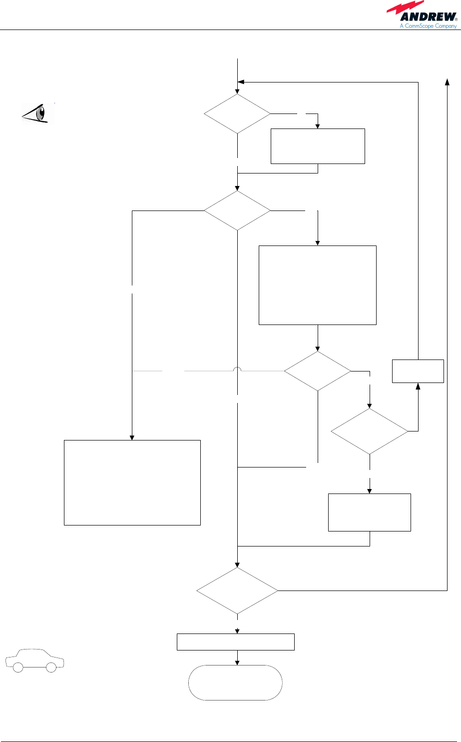
Commissioning the ION-M4/8 19"
Start
Mechanical installation
Prepare 19" rack for RU mounting with
guide rails. Weight of the RU is approx.
43 kg.
Manual for Remote
Unit
Electrical connections
Connect grounding cable and ground the
RU at connection terminals.
Mains
Switch mains power on. Switch mains
switches at PSU module at RU on.
Philips
screwdriver
RF connection
Connect antenna cable to antenna port.
Optical connections
Plug the optical fibre with E2000 APC8°
connector into the connector of the RU.
Mechanical installation
Mount RU to 19" rack, ensure suffient air
flow above and below the unit and avoid
thermal short circuits.
Preperation
Unpack RU and RU accessories.
External devices
Connect external devices to the external
in or alarm out connectors of the RU.
Guide rails
Screw
driver
Electrical connections
Connect AC (DC) power to the
connection terminals. Ensure there is a
circuit breaker between mains and RU.
4 Commissioning
Page 33
Output:
All RUs okay.
Go to MU
External error
Check externally connected devices.
Check fibre loss of optical link.
Check optical connectors.
Clean optical connectors.
Check optical output power of corresponding
OTRx at master unit.
ALC alarm: Decrease DL input power of
affected band.
VSWR alarm: Check antenna and cable.
LED status
Proceed to MU to set up the SW
Orange
Yes
Internal Error
Check LEDs at modules.
Change power supply.
Reduce environmental temperature.
Eliminate thermal short circuit.
Disconnect and connect mains.
MU: Change amplifier setting at MU
controller
Red
LED statusOrange
Green
Red
Finished setting
up all RUs?
Green
Spare Module or
spare RU available?
Yes
Contact customer
service
No
Yes
RU status LED
on?
Check LED and power switch
of the PSU modules
Check mains cabling.
Check mains power.
No
No
Replace
Module / RU

User’s Manual for
ION-M4/8 19"
Page 34 M0132AVA_FCC.doc
For your notes:

5 Alarms
Page 35
5. ALARMS
5.1. BITE AND ALARMS
The Built-In Test concept comprises the monitoring of the power supplies, the power
amplifiers and the optical interface.
All alarms occurring can be checked via software at the master unit.
5.2. HANDLING OF ALARMS
As soon as the software acknowledges a valid alarm, a message is transmitted to the
master unit.
If the reason for the alarm has been cleared or if the alarm should continue, a new
alarm message will not be repeated. If there was an interruption of at least five
seconds after acknowledgement, a new alarm message will be generated.
5.3. ALARM STATUS
For details refer to the corresponding software documentation of the master unit.
5.4. TROUBLESHOOTING
The status of the remote unit can be checked via the ION-M Master Unit (for details
please refer to the software manual of the Master Controller). Locally, the status can
be checked at the alarm board, see chapter 5.5 Status LED Alarms.
5.5. STATUS LED ALARMS
For local supervision, an LED alarm board is provided. For layout and detailed
description, please refer to chapter 3.2.2 Alarm Board.
User’s Manual for
ION-M4/8 19"
Page 36 M0132AVA_FCC.doc
The following table shows the coding for the status LED and possible on-site
measures that could be checked before referring to the master unit alarm list:
Status LED indication Alarms Possible on-site measures
Green No alarm Æ
Status ok
Alarms not directly related to RU:
External alarms Check externally connected devices.
Optical alarm Rx
Check fibre loss of optical link.
Check optical connectors.
Clean optical connectors.
(MU: Check optical output power of
corresponding OTRx at master unit).
Orange
ALC alarm (MU: Decrease DL input power of
affected band).
Alarms directly related to RU:
Power 28 V Change power supply.
Replace the affected remote unit.
Temperature Reduce environmental temperature.
Eliminate thermal short circuit.
Fan Disconnect and connect mains. Fans
should run briefly.
I²C Disconnect and connect mains.
Optical alarm Tx -
Red
A
mplifier “Power
Down” (MU: Change amplifier setting at MU
controller).
Status LED off Mains Check power switch.
Check mains cabling.
Check mains power.
table 5-1 Status LED alarm coding
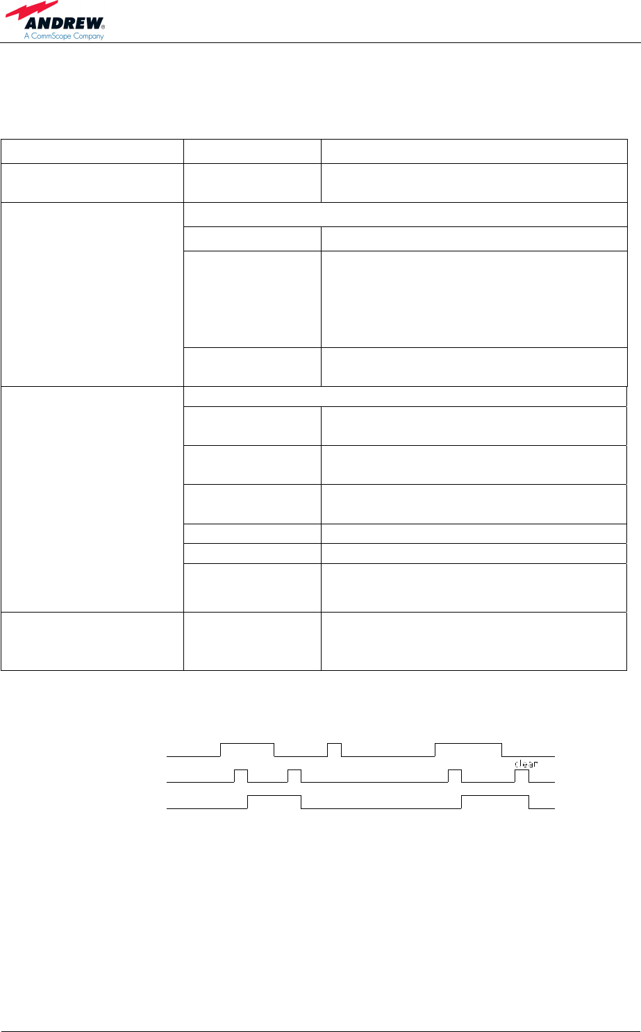
V1651A2
clear
Alarm LED
Alarm transmit
Alarm cause
raise
> 5 s < 5 s
raise
> 5 s
figure 5-1 Alarm triggering

6 Maintenance
Page 37
6. MAINTENANCE
6.1. GENERAL
Read the health and safety warnings in chapter 1.2 Health and Safety Warnings.
) Note: The remote unit does not require preventative maintenance
measures.
Maintenance of the ION-M4/8 19" should be performed by replacing only
components that are contained in this chapter. In order to maintain warranty, take
care not to damage unintentionally the seals on the modules.
) Note: When sending back the unit, use an appropriate packaging, see
chapter 7.2.3 Environmental and Safety Specifications. We
strongly recommend using the original packaging!
) Note: Defect parts should only be replaced by original parts from the
supplier. All interventions inside the housing are at one’s own risk.
) Note: During maintenance ensure the remote unit has been
disconnected from mains.
) Note: Before disconnecting any cables, label any unlabelled cables to
ensure correct re-connection.
) Note: If any system components where changed (DPX/OTRX/PA) a new
“HW discovery” command needs to be carried out and system
gain checked.
For most maintenance procedures appropriate tools are required to ensure correct
handling. All these tools can be ordered from the supplier. For screwing procedures
observe that all our screws have a right-hand thread, i.e. for fastening the screws
turn the tool clockwise and for unscrewing them turn it counter-clockwise.
User’s Manual for
ION-M4/8 19"
Page 38 M0132AVA_FCC.doc
6.2. REPLACEMENT OF COMPONENTS
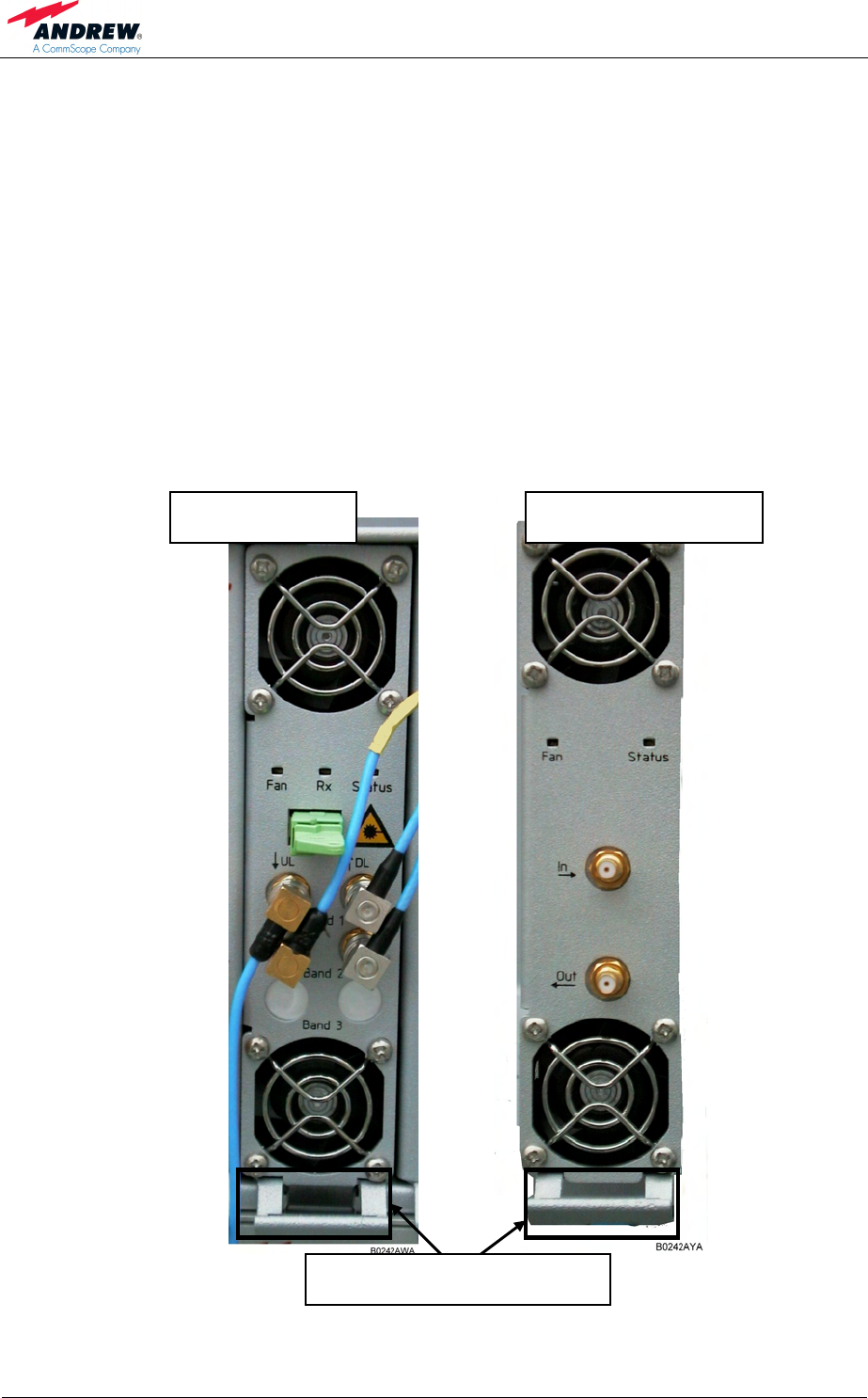
6.2.1. Replacement of Amplifier and Optical Plug-in Modules
For replacement of all plug-in modules, i.e. the OTRx, DPX and the amplifier
modules except for the power supply modules, the following procedure applies:
) Note : Before plugging or unplugging any of the modules, disconnect
mains by unplugging the IEC power connector.
) Note : As the modules are heavy, take appropriate measures to avoid
injury.
) Note: Before disconnecting any cables, label any unlabelled cables to
ensure correct re-connection.
figure 6-1 OTRx and amplifier modules, locking device
Locking device with spring
OTRx module Amplifier module
6 Maintenance
Page 39
- To get access to the power amplifier (PA), the sheet by which the PA is
covered must be removed. Therefore, unscrew the four M3x6 Phillips
countersunk-head screws.
- Take out the defect plug-in module carefully at the locking device from the
front side. Use your finger for pressing down the spring inside the locking
device.
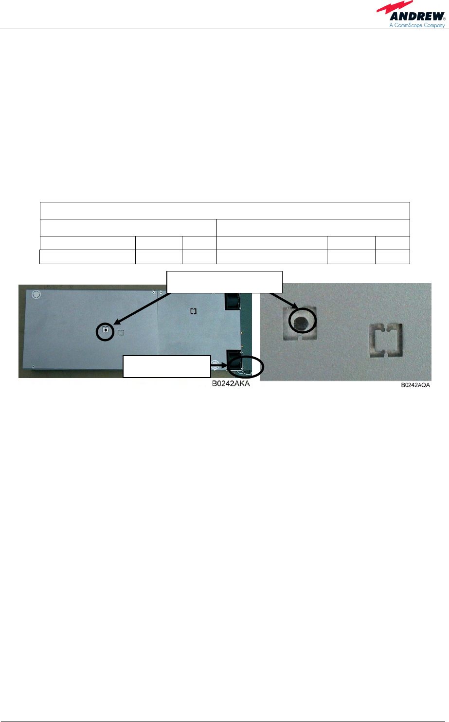
- When the PA module is exchanged, make sure the address, which can be
adjusted by means of the rotary address switch (see following illustrations) has
been set correctly according to the illustration on the labels and/ or the
following table:
PA addresses of switch positions:
Main Unit Extension Unit
800 MHz Band PA 1: 0 2nd 400 MHz Band PA 3: 0
400 MHz Band PA 2: 1 3rd 400 MHz Band PA 4 1
figure 6-2 Rotary address switch, location on PA
- Insert the new plug-in module until the stop by pressing down the spring of the
locking device.
- Re-connect mains by re-connecting the IEC power connector.
- Run HW discovery command on the Web interface of the Master Unit.
- Check whether the system has to be levelled again.
- Check the system gain.
Rotary address switch
Locking device
User’s Manual for
ION-M4/8 19"
Page 40 M0132AVA_FCC.doc
6.2.2. Replacement of Power Supply Plug-in Modules
The power supplies can be set up redundantly. Therefore, the system stays in
operation during replacement of one PSU. When replacing a broken PSU by a new
one, proceed in the following order:
- Disconnect mains from the defect PSU by unplugging the IEC power
connector.
- Pull out the defect PSU plug-in module carefully at the locking device from the
front side. Use your finger for pressing down the spring inside the locking
device.
figure 6-3 PSU module, locking device
- Note: To get access to the PSU, the sheet by which the PSU is covered must
be removed. Therefore, unscrew the four M3x6 Phillips countersunk-head
screws.
Locking device with spring
6 Maintenance
Page 41
- When the power supply module is exchanged, ensure the address, which can
be adjusted by means of the rotary address switch (see following illustrations),
has been set correctly according to the illustration on the labels and/ or the
following table:
Positions of PSU address switch:
PSU 1: 0
PSU 2: 1
figure 6-4 Rotary address switch, location on PSU
- Insert the new plug-in module until the stop by pressing down the spring of the
locking device.
- Reconnect mains by re-connecting the IEC power connector.
Rotary address switch
1
2
3

User’s Manual for
ION-M4/8 19"
Page 42 M0132AVA_FCC.doc
For your notes:
7 Appendix
Page 43
7. APPENDIX
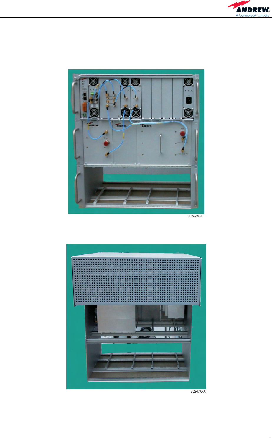
7.1. LAYOUT
figure 7-1 Layout of the ION-M4 19" remote unit, front side
figure 7-2 Layout of the ION-M4 19" remote unit, rear side
User’s Manual for
ION-M4/8 19"
Page 44 M0132AVA_FCC.doc
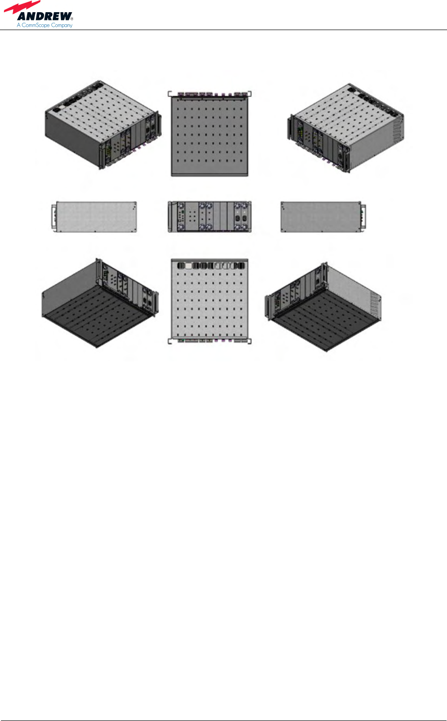
G3182Z000
figure 7-3 Cabinet drawing

7 Appendix
Page 45
7.2. SPECIFICATIONS
7.2.1. Electrical Specifications
Detailed ION-M4/8 19” – Product Specifications available on request.
User’s Manual for
ION-M4/8 19"
Page 46 M0132AVA_FCC.doc
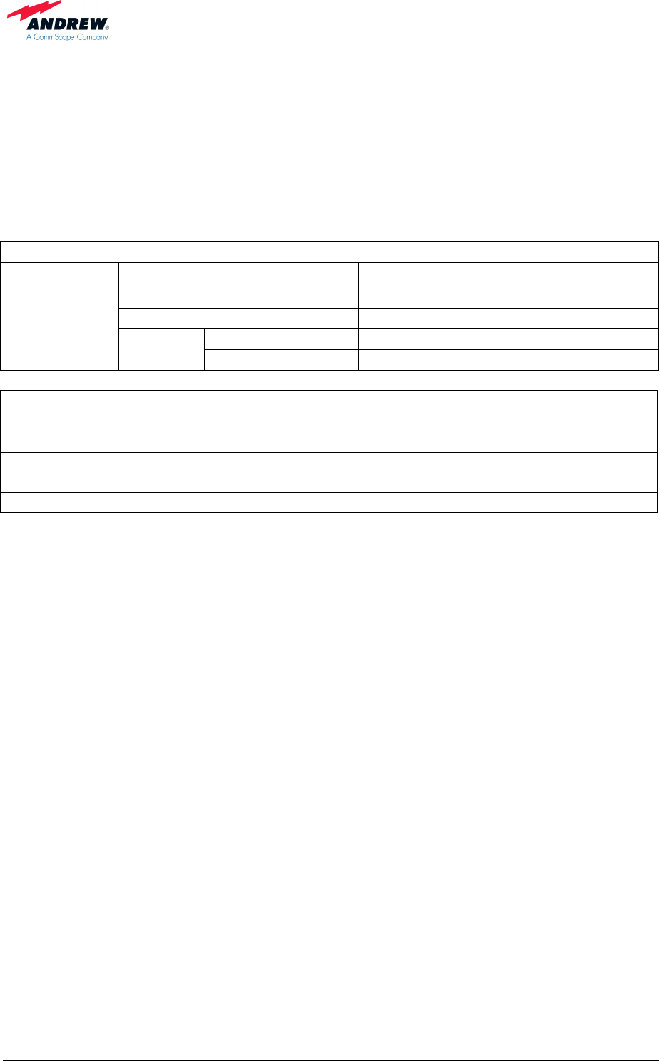
Interface
Connectors @ MU Single duplexed RF port or two non-
duplexed ports (QMA)
BTS types Micro: 33/43 dBm typical
Connector N Female
BTS Side
Antenna
port Return loss @ RU 15 dB typical
System Supervision and Control
Commands RF on/off
External control ports
Alarm Summary, Power supply, Optical UL and DL failure, RF
UL and DL failure, Temperature, Door open
Supervision Composite output power
7 Appendix
Page 47
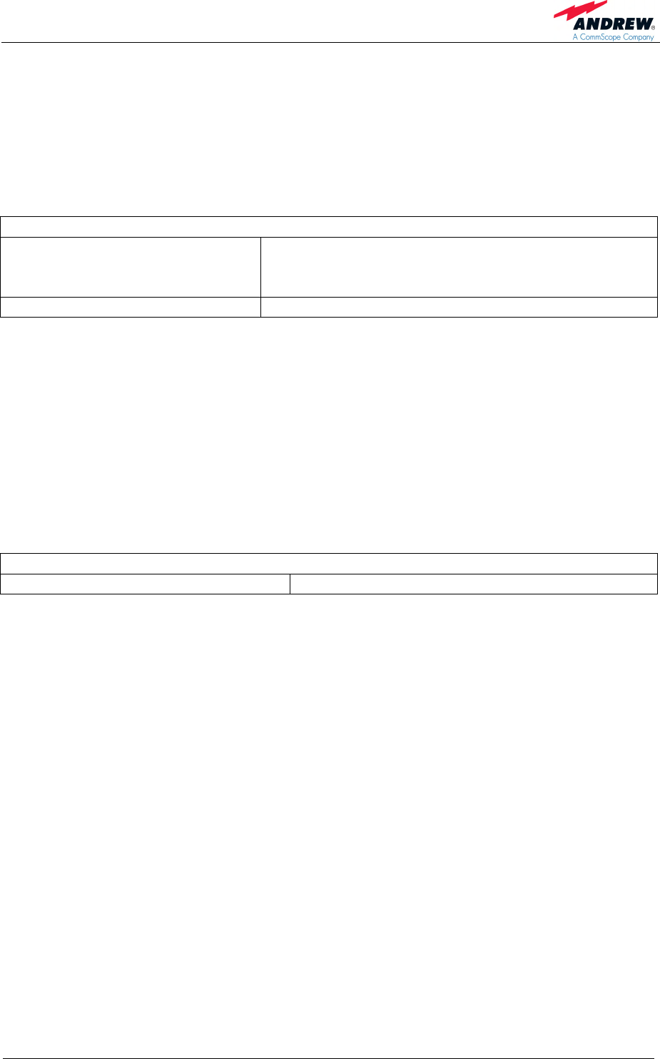
7.2.2. Mechanical Specifications
) Spacing required: 70 mm from the front air inlet and 70 mm from the rear
outlet of the subrack is compulsory. Do not block air inlet and outlet.
Horizontal mounting is compulsory.
Mechanical
Height, width, depth 4 HU x 19” x 487 mm (4 HU x 19” x 19.2 in)
4 HU with optional additional duplexer or/and
extension unit subrack
Weight (entire system) 43 kg (94.8 lb)
All figures are typical values.
All data is subject to change without notice.
7.2.3. Environmental and Safety Specifications
) Note: For detailed information, please refer to the Environmental and
Safety Specifications leaflet of the supplier, related to ETS 300 019
(European Telecommunication Standard).
Environmental
Temperature range +5 °C to +40°C
All figures are typical values.
All data is subject to change without notice.

User’s Manual for
ION-M4/8 19"
Page 48 M0132AVA_FCC.doc
7.3. SPARE PARTS
The following lists contain all parts available for the Remote Unit. The configuration of
the delivered unit meets the requirements of the customer and can differ depending
on the state of the delivery.
Maintenance of the ION-M4/8 19" should be performed on an FRU (Field
Replaceable Unit) basis only. The following spare parts lists only contain units that
can be replaced without tuning or soldering work. To replace an FRU, use the
appropriate tools. Replacement tools may be ordered from the supplier. If any FRU
not contained in the following list needs to be replaced, please contact customer
service for additional instructions.
Spare Parts List of the Remote Unit ION-M4/8 19"
Designation ID No FRU
ION-M4/8 19" 7609239-0001
Alarm Card with Ext. Controller 7611246-00
OTRX Drawer 7610964-00
Crossbandcoupler Drawer 7610959-00
Amplifier Drawer 450-490 MHz 7610960-00
Amplifier Drawer 800 MHz 7610961-00
PSU Drawer 7610963-00
Main Subrack 7610958-00
Dpx UL- active 486.15-486.575 7611284-00
Dpx UL-active 806-824 851-869 7611286-00
DPX Subrack 7611217-00
Manual for ION-M4/8 19" 7613191-00
The manufacturer reserves the right to replace the spare parts listed above by
equivalent substitutes.

8 Index
Page 49
8. INDEX
A
Abbreviations.......................................................... 7
Address of Andrew Wireless Systems GmbH....... 12
Alarm Board.......................................................... 19
Alarm Coding of Status LED................................. 38
Alarms
Alarm Status .................................................... 37
Bite and Alarms ............................................... 37
Handling of Alarms .......................................... 37
List ................................................................... 37
RU ................................................................... 37
Status LED....................................................... 37
Amplifier
Address Switch................................................ 41
Replacement.................................................... 40
Amplifier Drawer................................................... 22
Andrew Solutions.................................................. 10
B
Block Diagram ...................................................... 15
C
Cabinet Drawing................................................... 46
Cabling ................................................................. 29
Commissioning
General............................................................ 33
Components ......................................................... 16
Connection
AC.................................................................... 30
Connection Rules
Optical Fibres................................................... 31
Optical-Fibre Cables ........................................ 31
Connections
Antenna ........................................................... 31
Layout.............................................................. 29
Power .............................................................. 30
Power and Grounding...................................... 30
Contact Addresses ............................................... 11
Crossband-Coupler Drawer.................................. 22
Customer Support Addresses............................... 11
D
Declaration of Conformity ..................................... 10
Duplexer Subrack................................................. 26
F
Functions.............................................................. 13
G
Grounding............................................................. 30
H
Health and Safety Warnings................................... 9
I
Installation
Electrical.......................................................... 28
Mechanical ...................................................... 27
Introduction........................................................... 13
L
Layout
Cabinet Drawing .............................................. 46
Front ................................................................ 45
LED ...................................................................... 37
Levelling ............................................................... 32
M
Main Subrack 19 .................................................. 17
Maintenance......................................................... 39
Mounting
General............................................................ 27
O
OTRx
Replacement ................................................... 40
OTRx Drawer ....................................................... 21
P
Power Supply
Replacement ................................................... 42
PSU
Address Switch................................................ 43
PSU Drawer ......................................................... 24
R
Replacement of
Power Supply .................................................. 42
Replacement of Components
Amplifier........................................................... 40
OTRx ............................................................... 40
S
Spare Parts .......................................................... 50
Specifications
Electrical.......................................................... 47
Environmental and Safety................................ 49
Mechanical ...................................................... 49
Status LED
Alarm Coding................................................... 38
T
Troubleshooting.................................................... 37