Andrew Wireless System M717E19P ION-M Remote Unit for cellular systems User Manual ION M7P 17EP 19P M2 Cabinet PA 110265 EN GB indd
Andrew Wireless System ION-M Remote Unit for cellular systems ION M7P 17EP 19P M2 Cabinet PA 110265 EN GB indd
Contents
- 1. data seet
- 2. installetion manual
- 3. user manual
data seet
PRODUCT
SPeCifiCaTiOn
multiple operators to use multiple technolo-
gies and move their signals simultaneously
from a cluster of base station to a number of
remote locations over the same fiber.
The ION-M optical distribution system is a
cost-effective coverage solution for dense
urban areas, tunnels, subways, airports,
convention centers, high-rise buildings and
other locations where physical structures
increase path loss.
The combination of these units gives maxi-
mum flexibility while providing a scalable
solution. The system is optimized for GSM,
LTE, CDMA and WCDMA signals in the
700 MHz, 1900 MHz and 1700/2100
MHz bands. Furthermore it is provisioned
for future modulation schemes and frequency
bands.
The ION can be easily set-up and super-
vised from a graphical user interface (GUI).
Remote units are commissioned through the
use of built-in test equipment. An auto level-
ling function compensates for the optical link
loss making installation easy and quick.
The entire system as well as complete net-
work of systems can be managed remotely
most efficiently by Commscope`s A.I.M.O.S,
which includes alarm monitoring, task auto-
mation, statistics, inventory management and
ION-M7P/17EP/19P
many more features. Should a sophisticated
interface not be required, the master unit
can be directly connected to the alarm
interface of a base station via its contact
relay.
• Reduced visual impact form factor
• Optimized power consumption
• Efficient, high power amplifier
• Multi-operator support
• Complete operations and management
system for configuration and alarming
• OMC with SNMP according to X.733
standard
• With reference to 3GPP TS25.143/
TS25.106/ 36.143/TS36.106 and
3GPP2C.S0051-0
• Single fiber for multiple bands and
multiple remotes
• Easy installation and commissioning
CommScope’s ION-M7P/17EP/19P is
a multi-band, multi-operator remote unit
configuration used in conjunction with a
master unit in the ION optical distribution
system. By supporting the entire AWS-3
spectrum, faster and more reliable wireless
service is ensured and network quality can
be improved.
This system transports up to four fre-
quency bands simultaneously (700 MHz,
1700/2100 MHz, 1900 MHz), providing
a cost-effective solution for distributing capac-
ity from one or more base stations.
The ION system transports signals on the RF
layer in a very cost-effective manner enabling
ION® is the unified platform
for all conceivable optical
distribution scenarios.
The ION optical distribution
system leads the industry in
flexibility while minimizing
overall deployment cost.
Multi-band, Multi-operator Remote Optical System
Support of AWS-3 Spectrum
ION® Series

SPECIFICATIONS
ION-M7P/17EP/19P - Product Specification
Electrical
Mains power, Vac
................nominal..............100 to 240
................operating .............85 to 264
Mains power, Vdc
................nominal..............48 to 60
................operating .............36 to 72
Power consumption, Watts..................850
Optical
Optical Link
Connectors ..................E2000/APC 8°
Optical return loss, dB ......................45
Fibre type ..................................Single mode E9/125 µm
Optical link budget, dB .....................0 to 10
Composite input power @ OTRx master side, dBm
................700 MHz .............3.0 nominal
................AWS1700/2100 .........3.0 / 2.5 nominal
................PCS1900 .............3.0 / 2.5 nominal
Interface
BTS Side (SMA)
Number of connectors ...Standard
................700 MHz .............4
................AWS1700/2100 .........4
................PCS1900 .............4
System optimized for BTS power, dBm
..................................33
..................................46
Antenna port
Connector ..................................4.3-10
RF output power ............................see band specification
Return loss, dB ..............................15
Commercial 700 MHz
Frequency range, MHz
................Uplink ..............698 to 716
..................................776 to 787
................Downlink .............728 to 757
RF output power per carrier, dBm***
Number of Carriers 1 2 4 8
LTE 43 40* 37 34
DL output tolerance over frequency, dB.........±1
DL output tolerance over temperature, dB .......±0.5
Spurious emission...........................<-13 dBm / 1 MHz
Input ICP3, dBm**
................ICP3 optimized ..........-11 min.
................Noise figure optimized ......-18 min.
Noise figure, dB**
................ICP3 optimized ..........+10 max.
................Noise figure optimized ......+6 max.
..................................4.5
AWS1700/2100
Frequency range, MHz
................Uplink ..............1710 to 1780
................Downlink .............2110 to 2180
RF output power per carrier, dBm***
Number of Carriers 1 2 4 8
CDMA 42.5 39.5 36.5 33.5
LTE 43 40* 37 34
UMTS 42.5 39.5 36.5 33.5
DL output tolerance over frequency, dB.........±1.1
DL output tolerance over temperature, dB .......±0.5
Spurious emission...........................<-13 dBm / 1 MHz
Input ICP3, dBm**
................ICP3 optimized ..........-12 min.
................Noise figure optimized ......-18 min.
Noise figure, dB**
................ICP3 optimized ..........+11 max.
................Noise figure optimized ......+6 max.
..................................4.5
* 2 dB reduction of Pout @ carrier bandwidth < 5 MHz
** from Reference point B to A
*** PAR 7.5 dB @ 0.1 %
All figures are typical values unless otherwise stated

SPECIFICATIONS
PCS1900
Frequency range, MHz
................Uplink ..............1850 to 1915
................Downlink ............1930 to 1995
RF output power per carrier, dBm***
Number of Carriers 1 2 4 8
GSM 43 40 37 34
CDMA 42.5 39.5 36.5 33.5
LTE 43 40* 37 34
UMTS 42.5 39.5 36.5 33.5
DL output tolerance over frequency, dB ........±1.1
DL output tolerance over temperature, dB .......±0.5
Spectrum emission mask .. . . . . . . . . . . . . . . . . . <-13 dBm / 1 MHz
Input ICP3, dBm**
................ICP3 optimized..........-12 min.
................Noise figure optimized......-18 min.
Noise figure, dB**
................ICP3 optimized..........+11 max.
................Noise figure optimized......+6 max.
..................................4.5
System Supervision and Control
Commands .................................RF on/off
..................................4 external control ports
Alarms ..................................Summary
..................................Power Supply
..................................Optical UL and DL
..........................................failure
..................................RF UL and DL failure
..................................Temperature
..................................4 external alarm inputs
Supervision .................................Composite output
..........................................power
ION-M7P/17EP/19P - Product Specification
Mechanical****
Height, width, depth, mm (in)................824 x 176 x 220
..........................................(32.4 x 6.9 x 8.7)
Weight, kg (Ib) .............................27 (59.4)
Environmental
Operating temperature range, °C.............-33 to +50
Ingress protection
RF part ............IP67
Fan part ...........IP55
Minimum SW Requirements for Basic Support
ION-M SW V7.0.1
Ordering Information
ION-M7P/17EP/19P . . . . . ..................7714179*****
Depending on the selected options and the configuration the ordering material number
contains an identifying suffix.
Extension Unit Options
No connection to extension unit possible.
Corresponding Master Unit OTRx
OTRx 70-85/90/17-21 MU-G ..............7604304-XX
* 2 dB reduction of Pout @ carrier bandwidth < 5 MHz
** from Reference point B to A
*** PAR 7.5 dB @ 0.1 %
**** Spacing required 50 mm (1.97 in) around unit
***** Subpopulations possible
All figures are typical values, unless otherwise stated.
SPECIFICATIONS
www.commscope.com
Visit our Web site or contact your local Commscope representative for more information.
© 2016 Commscope, Inc. All rights reserved.
All trademarks identified by ® or ™ are registered trademarks or trademarks, respectively, of Commscope, Inc.
This document is for planning purposes only and is not intended to modify or supplement any specifications or warranties relating to Commscope products or services.
CommScope reserves the right to change all hardware and software characteristics without notice.
ION-M7P/17EP/19P - Product Specification
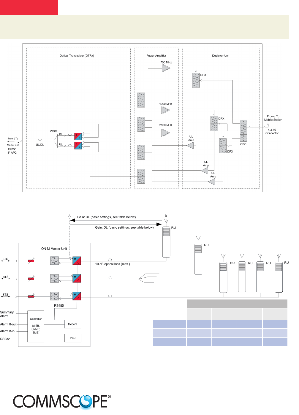
Gain DL Gain UL
ICP3
optimized
NF
optimized
ICP3
optimized
NF
optimized
700 MHz 40 dB 40 dB 40 dB 47 dB
PCS1900 40 dB 40 dB 39 dB 46 dB
AWS1700/2100 40 dB 40 dB 40 dB 47 dB
Design Principle ION System
Bulletin PA-110265-EN.GB (05/16)
WARNING:
This is NOT a CONSUMER device. It is designed for installation by FCC LICENSEES and QUALIFIED INSTALLERS.
You MUST have an FCC LICENSE or express consent of an FCC LICENSE to operate this device.
Unauthorized use may result in significant forfeiture penalties, including penalties in excess of $ 100,000 for each continuing violation.
ION-M7P/17EP/19P Remote Unit Design Principle - Combined Antenna Port