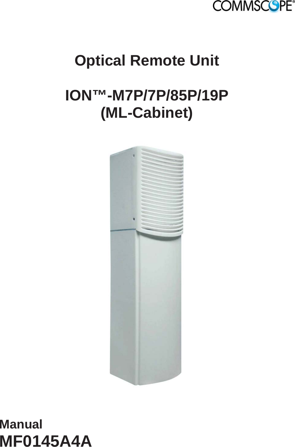
Andrew Wireless System M778519P ION-M7P/7P/85P/19P User Manual Manual for ION M Remote Unit
Andrew Wireless System ION-M7P/7P/85P/19P Manual for ION M Remote Unit
UserManual.wiki
>
Andrew Wireless System
>
M778519P User Manual
>
user manual
Contents
1.
user manual
2.
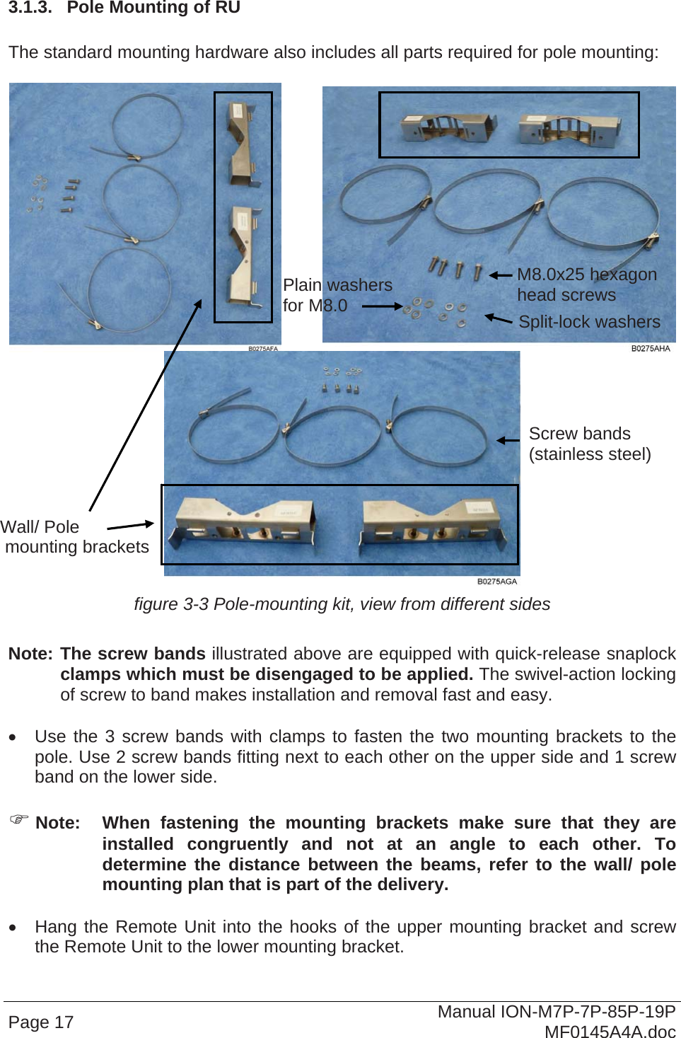
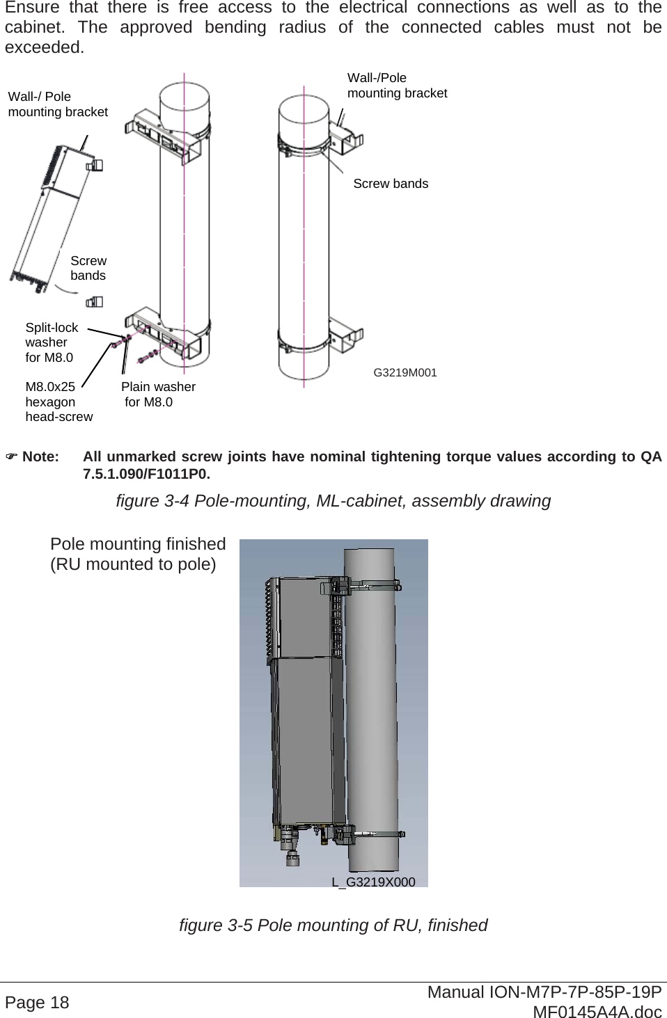
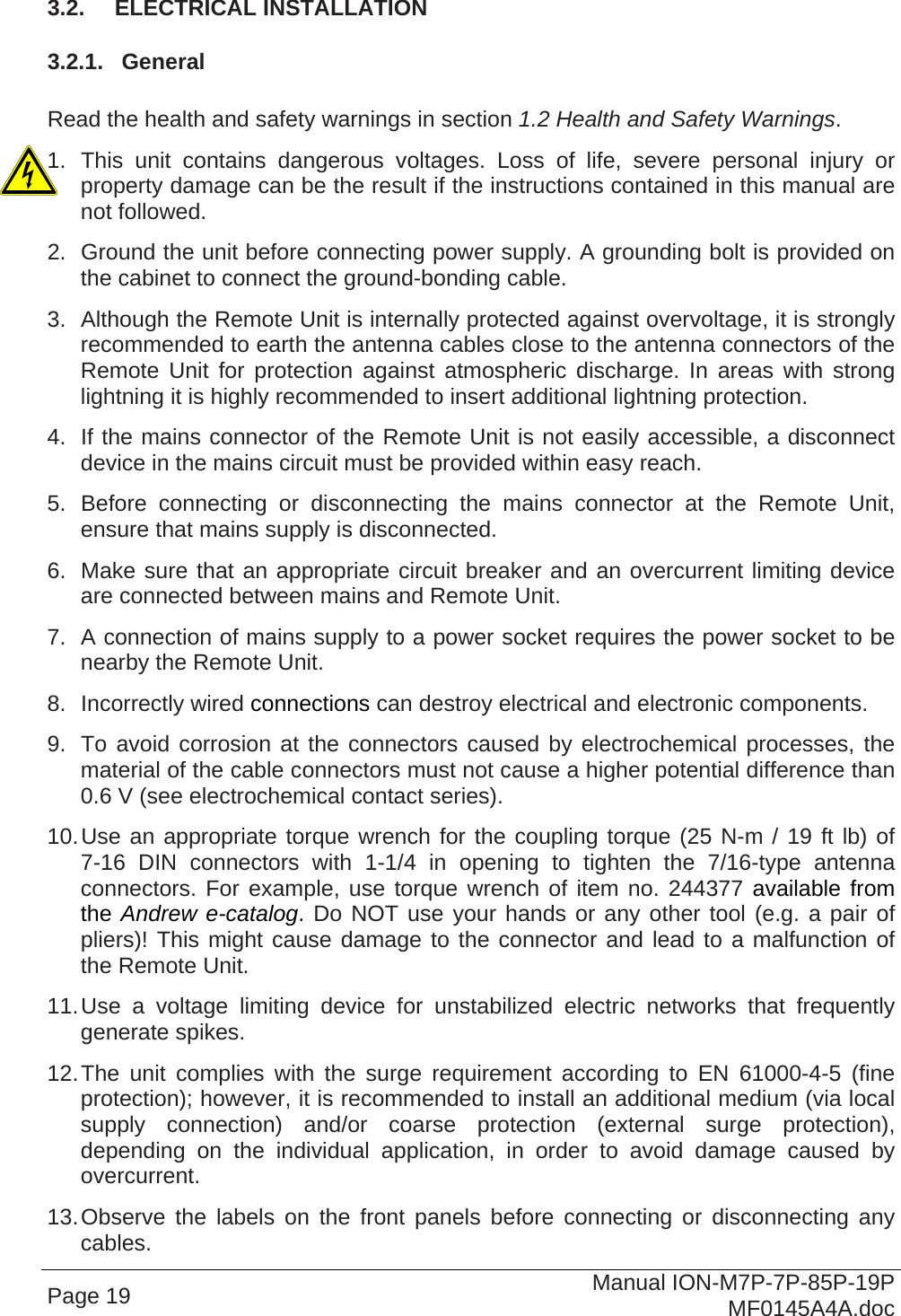
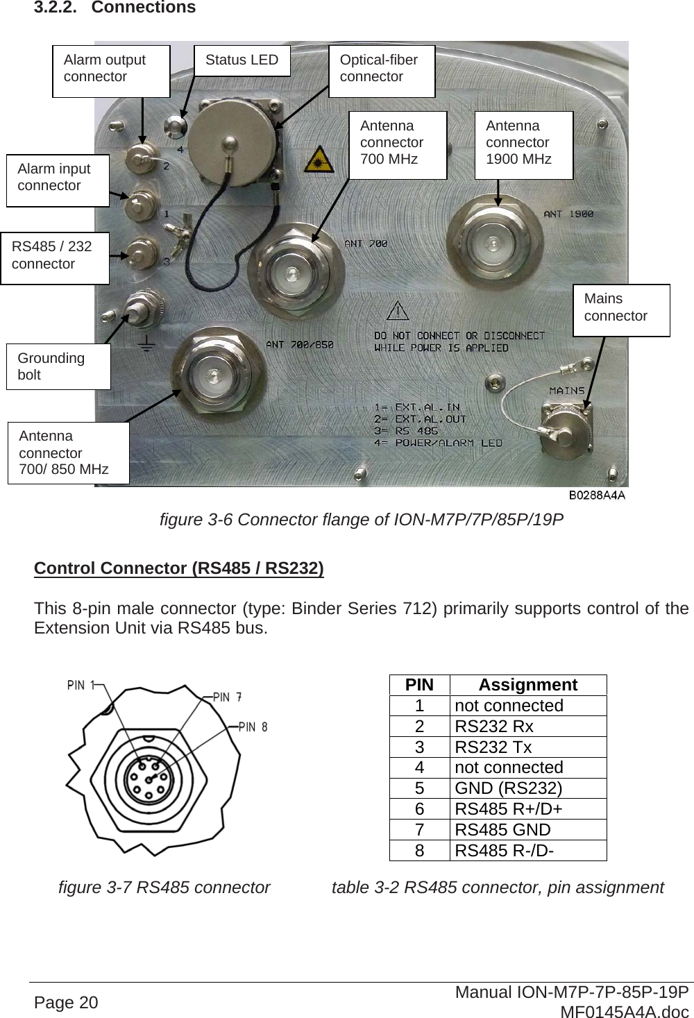
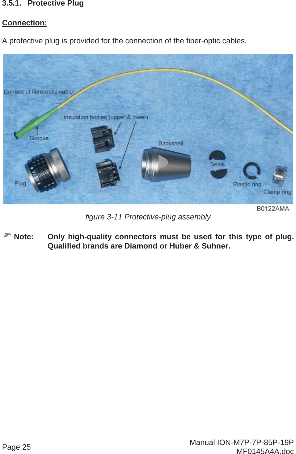
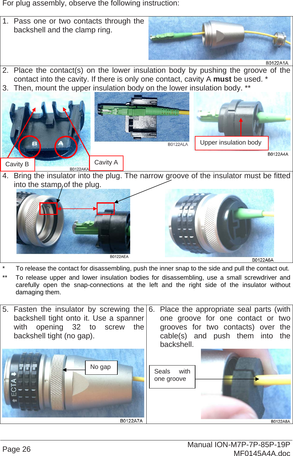
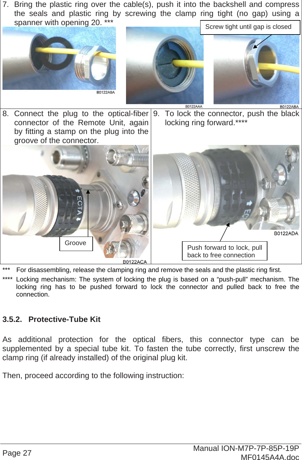
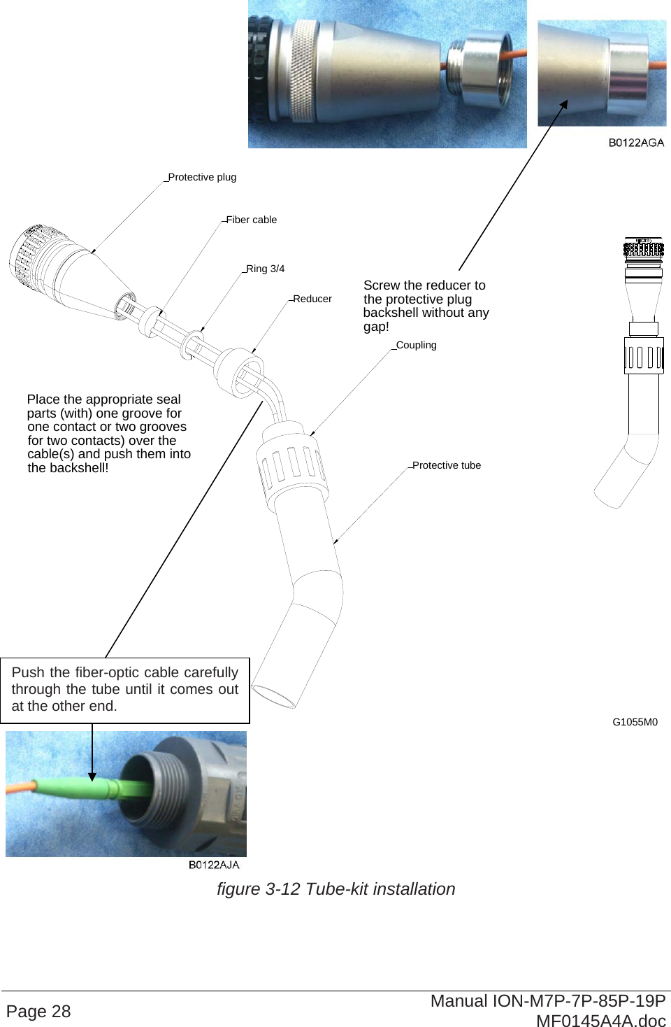
installation instruction
user manual
Navigation menu
Upload a User Manual
Namespaces
Wiki Guide
HTML
PDF
Info
Views
User Manual
Discussion / Help
Navigation