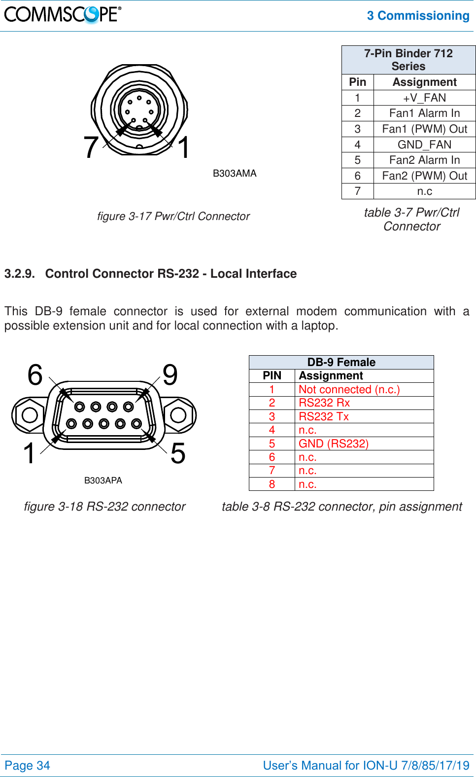
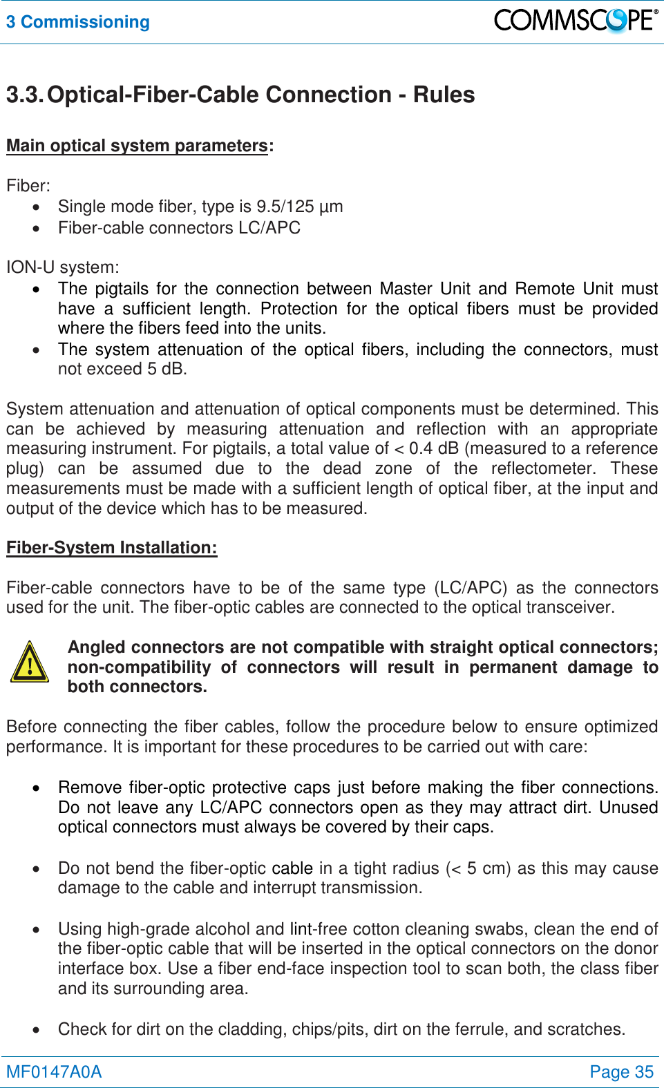
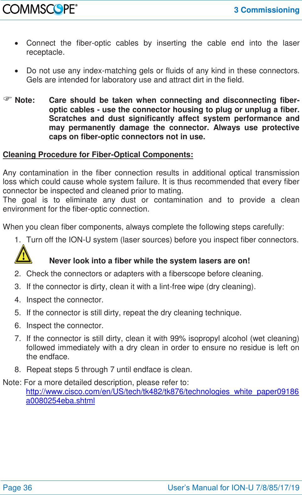
Andrew Wireless System U7885L1719P ION-U Remote Unit for cellular systems User Manual User s Manual for ION U LP RU
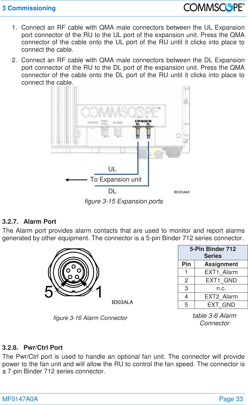
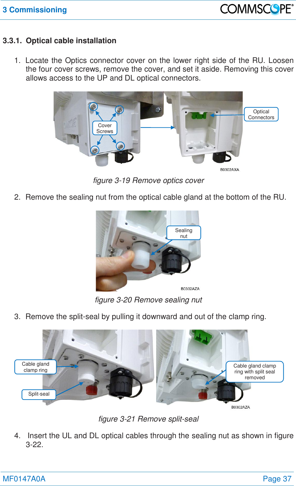
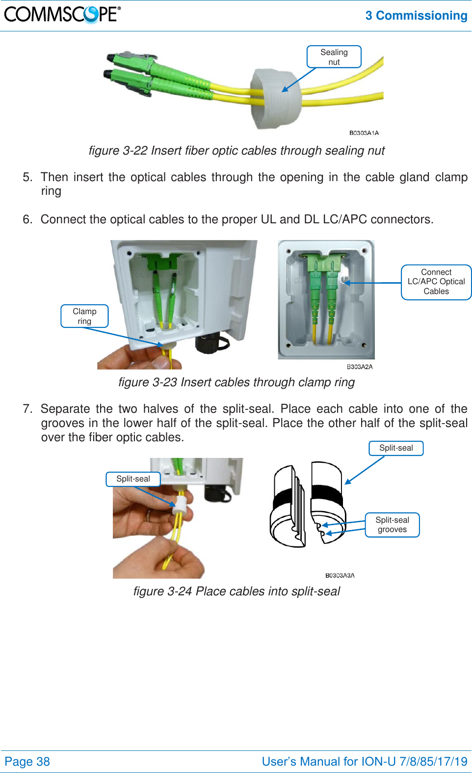
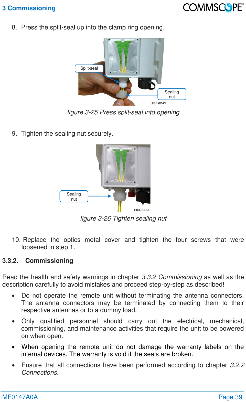
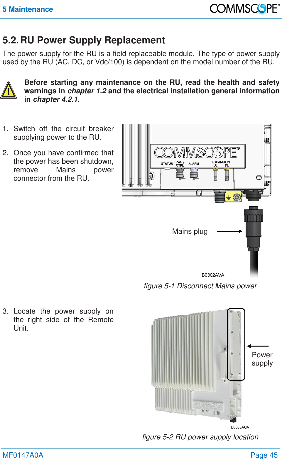
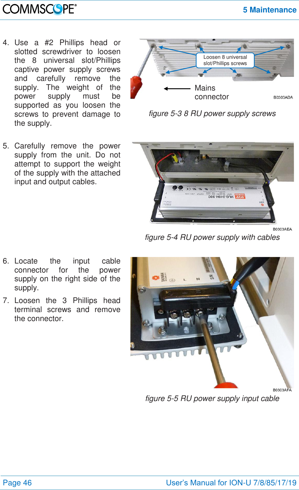
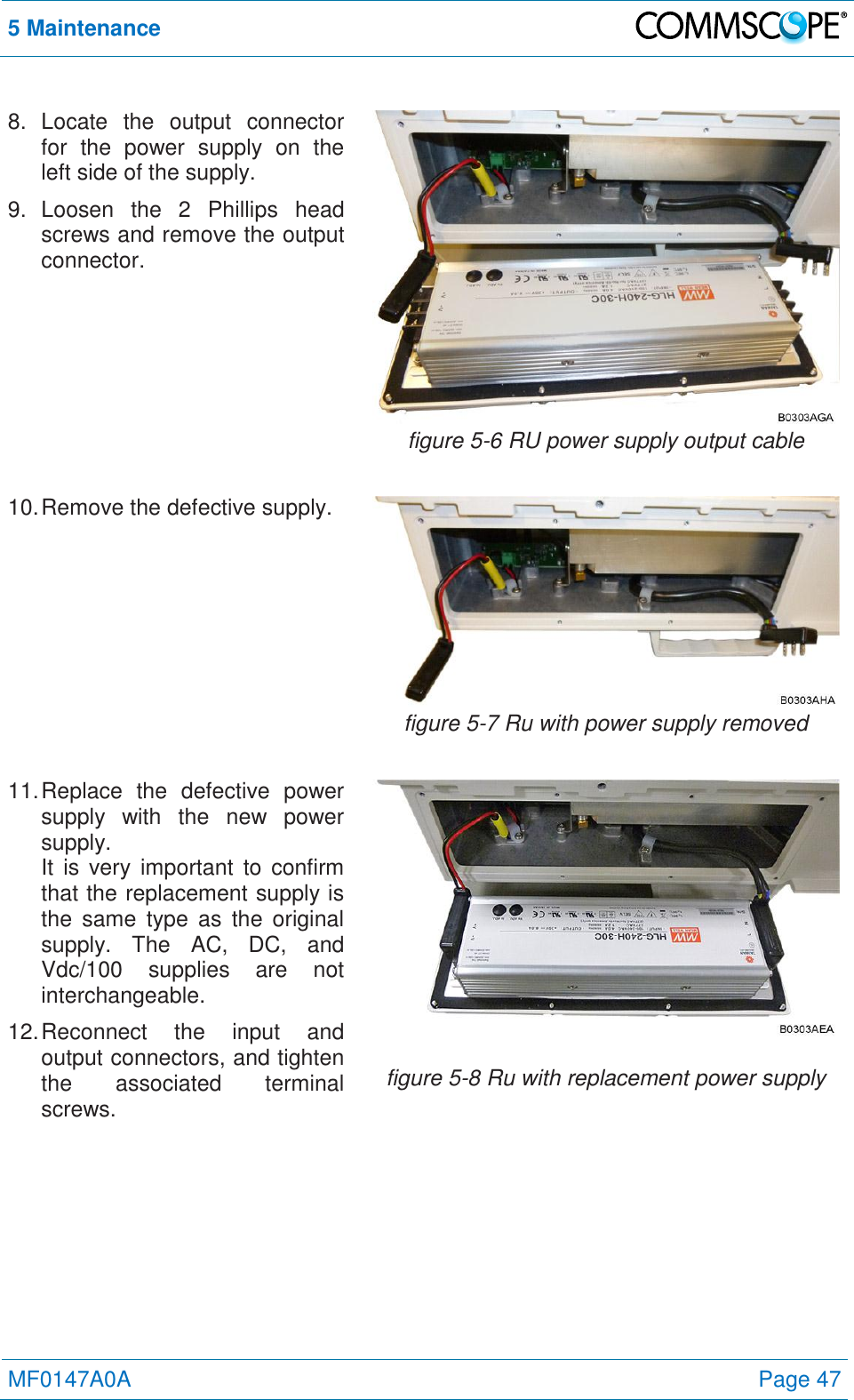
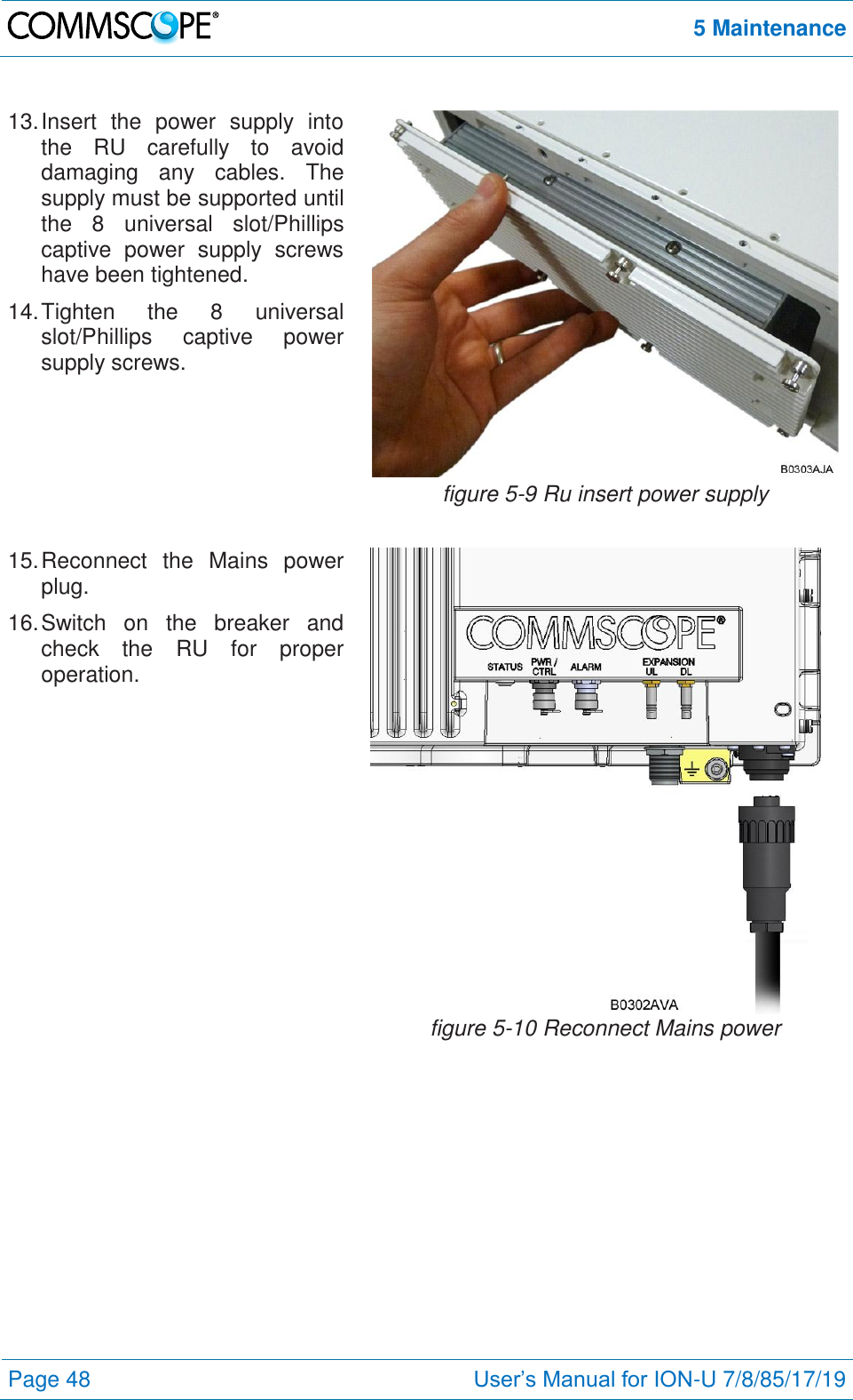
Andrew Wireless System ION-U Remote Unit for cellular systems User s Manual for ION U LP RU
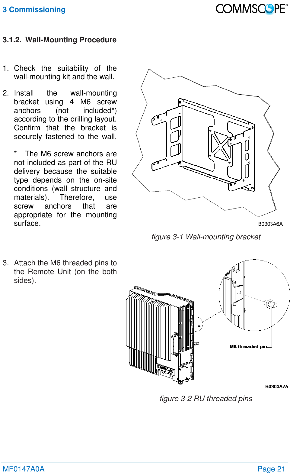
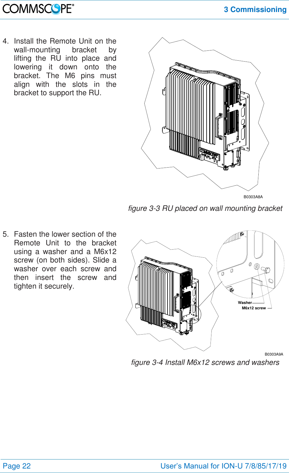
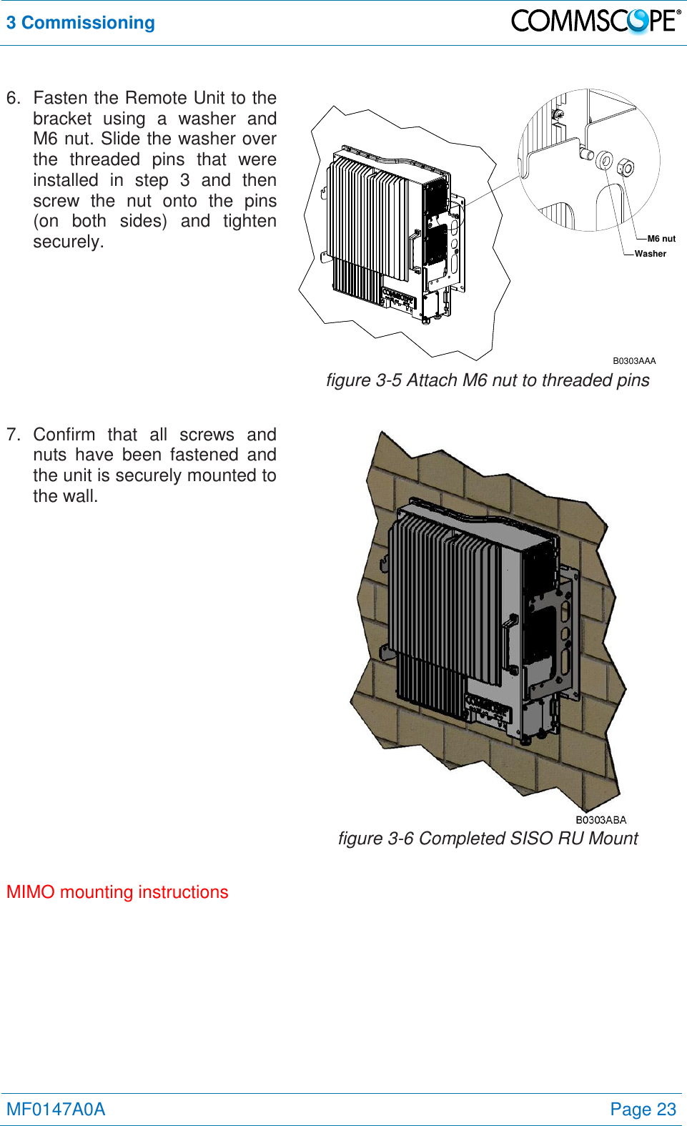
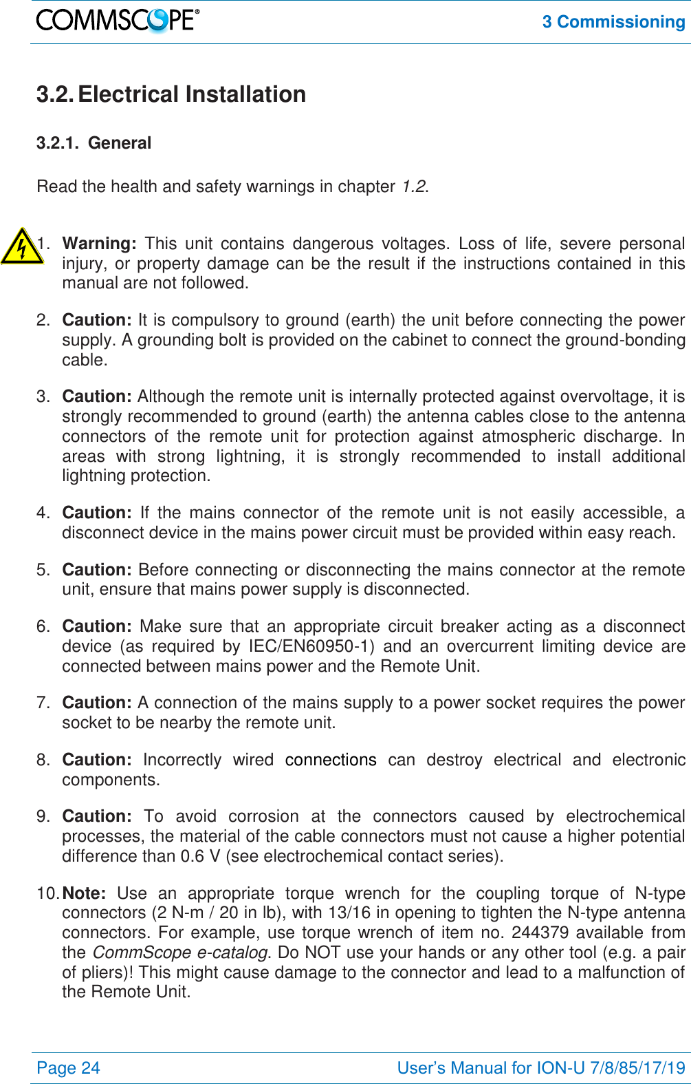
Contents
- 1. installation Instruction
- 2. user manual
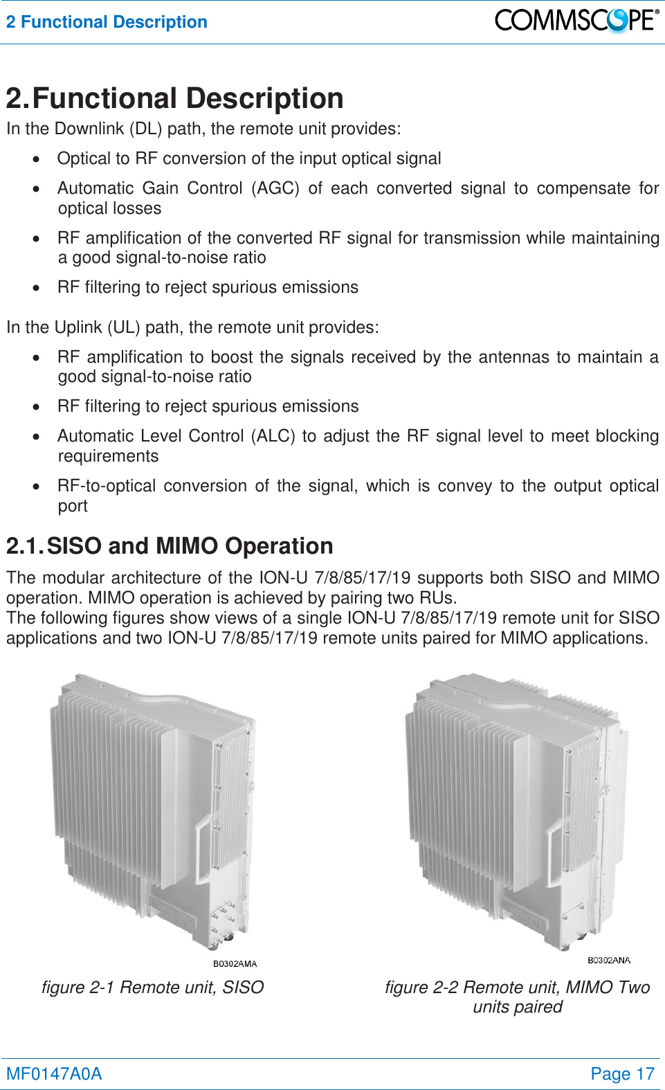
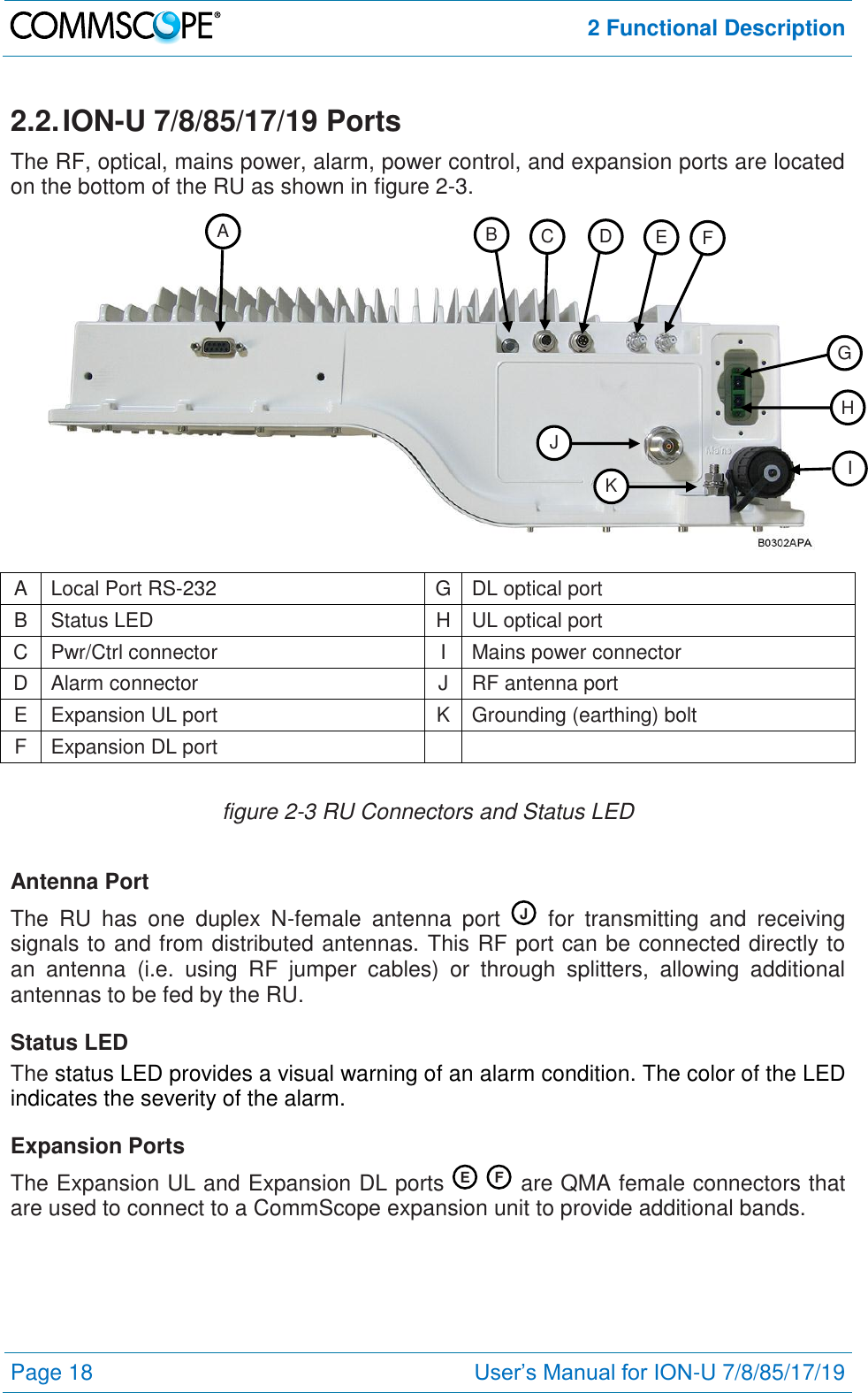
user manual
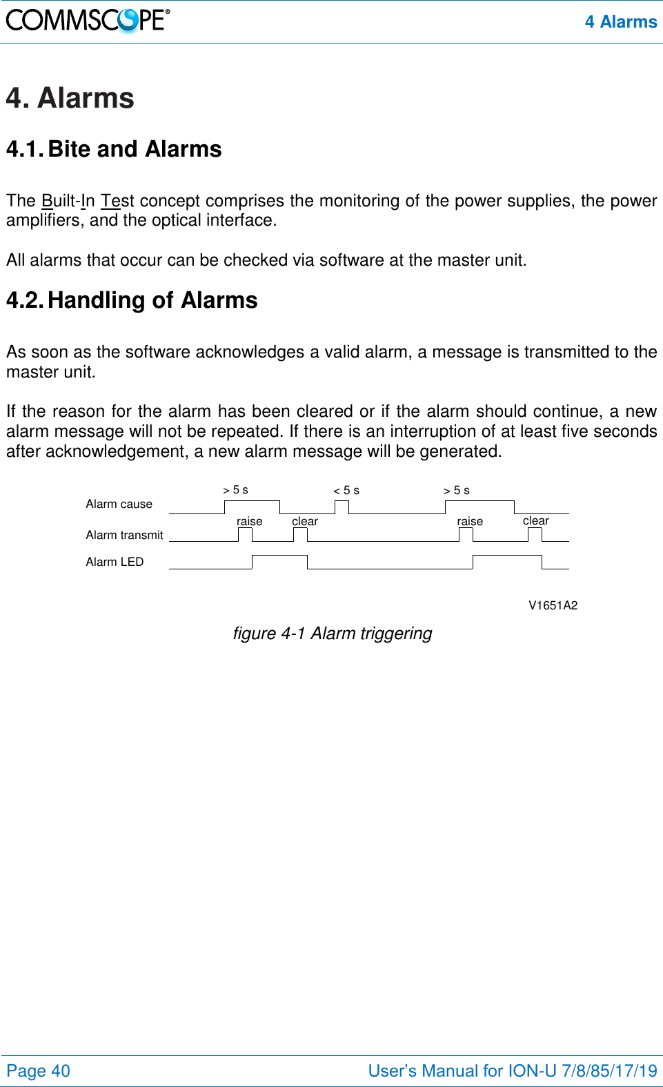
![1 General Page 8 User’s Manual for ION-U 7/8/85/17/19 1.2. Health and Safety Warnings 1. Danger: Obey all general and regional installation and safety regulations relating to work on high voltage installations, as well as regulations covering correct use of tools and personal protective equipment. 2. Danger: Laser radiation! Do not stare into the beam; do not view it directly or with optical instruments. 3. Danger: Before opening the unit, disconnect mains power. 4. Danger: Due to power dissipation, the remote unit may reach a very high temperature. Do not operate this equipment on or close to flammable materials. Use caution when servicing the unit. 5. Warning: Read and obey all the warning labels attached to the unit. Make sure that all warning labels are kept in a legible condition. Replace any missing or damaged labels. 6. Warning: It is the responsibility of the network provider to implement prevention measures to avoid health hazards associated with radiation from the antenna(s) connected to the unit. 7. Warning: Make sure, access is restricted to qualified personnel. 8. Warning: Only licence holders for the respective frequency range are allowed to operate this unit. 9. Warning: Make sure the repeater settings are correct for the intended use (refer to the manufacturer product information) and regulatory requirements are met. 10. Warning: Use this equipment only for the purpose specified by the manufacturer. Do not carry out any modifications or fit any spare parts, which are not sold or recommended by the manufacturer. This could cause fires, electric shock, or other injuries. 11. Warning: For installations, which have to comply with FCC RF exposure requirements, the antenna selection and installation must be completed in a way to ensure compliance with those FCC requirements. Depending on the RF frequency, rated output power, antenna gain, and the loss between the repeater and antenna, the minimum distance D to be maintained between the antenna location and human beings is calculated according to this formula: ]/[][][24cmmWmWcm PDPD where P (mW) is the radiated power at the antenna, i.e. the max. rated repeater output power in addition to the antenna gain minus the loss between the repeater and the antenna.](https://usermanual.wiki/Andrew-Wireless-System/U7885L1719P.user-manual/User-Guide-1935238-Page-8.png)