Andrew Wireless System UEBL2323 ION-B Extension Booster for cellular systems User Manual
Andrew Wireless System ION-B Extension Booster for cellular systems
Contents
- 1. Installation Instruction
- 2. user manual
user manual

ION-B User Manual (MN024-
15)_n_20150730.docx Page 1
User’s Manual
for
ION-B Systems
MN024-15

User’s Manual for ION-B Systems
Page 2 ION-B User Manual (MN024-15)_n_20150730.docx
DISCLAIMER:
This document has been developed by CommScope, and is intended for the use of its
customers and customer support personnel. The information in this document is subject to
change without notice. While every effort has been made to eliminate errors, CommScope
disclaims liability for any difficulties arising from the interpretation of the information
contained herein. The information contained herein does not claim to cover all details or
variations in equipment, nor to provide for every possible incident to be met in connection
with installation, operation, or maintenance. This document describes the performance of the
product under the defined operational conditions and does not cover the performance under
adverse or disturbed conditions. Should further information be desired, or should particular
problems arise which are not covered sufficiently for the purchaser’s purposes, contact
CommScope.
CommScope reserves the right to change all hardware and software characteristics without
notice.
COPYRIGHT:
© Copyright 2015 CommScope Inc. All Rights Reserved.
This document is protected by copyright. No part of this document may be reproduced,
stored in a retrieval system, or transmitted, in any form or by any means, electronic,
mechanical photocopying, recording, or otherwise without the prior written permission of
CommScope.
TRADEMARKS
All trademarks identified by ® or ™ are registered trademarks or trademarks, respectively, of
CommScope. Names of products mentioned herein are used for identification purposes only
and may be trademarks and / or registered trademarks of their respective companies.
Andrew Wireless Systems GmbH, 15-June-2015

ION-B User Manual (MN024-
15)_n_20150730.docx Page 3
TABLE OF CONTENTS
1.1.About CommScope 18
1.2.International Contact Addresses for Customer Support 19
2.INTRODUCING ION-B 21
2.1.The Features 21
2.2.Brief Description of ION-B 21
2.3.ION-B Features 22
2.4.Typical ION-B Applications 23
3.EQUIPMENT OVERVIEW 25
3.1.Introduction 25
3.2.The ION-B Remote Unit and its relevant accessories 25
3.3.The ION-B Master Unit 28
3.4.ION-B additional options 32
4.TFAX REMOTE UNIT (RU) 33
4.1.The Main Tasks of the TFAx Remote Unit 33
4.2.Different Types of Remote Units 34
4.3.Warnings (to be read before Remote Units are installed) 36
4.3.1.Dealing with optical output ports 36
4.3.2.Choosing a Proper Installation Site for the RU 36
4.3.3.Handling Optical Connections 36
4.3.4.Antenna Connections - Connectors 37
4.3.5.Cleaning Procedure for RF Cable Connectors 38
4.3.6.Antenna Cable Connector Assembly 41
4.3.7.Correct Positioning of the Remote Unit and its Power Supply 43
4.3.8.Power Supply 43
4.3.9.Visual Alarms 44
4.3.10.Automatic Gain Control (AGC) 44
4.4.Case A Remote Unit 45
4.4.1.Specifications 45
4.4.2.TFAx Case A Installation 46
4.4.3.Installing a Case A Remote Unit WITHOUT the TKA kit 47
4.4.4.Installation of the Case A Remote Unit WITH the TKA04 Installation Kit 48
4.5.Case B Remote Unit 52
4.5.1.Specifications 52
4.5.2.TFAx Case B Installation 53
4.5.3.Installing a Case B Remote Unit WITHOUT the TKA Kit 53
4.5.4.Installation of the Case B Remote Unit WITH the TKA04 Installation Kit 56
4.6.Case R2 Remote Unit 59
4.6.1.Specifications 59
4.6.2.TFAx Case R2 Installation 60

User’s Manual for ION-B Systems
Page 4 ION-B User Manual (MN024-15)_n_20150730.docx
4.7.Case R2 MIMO Remote Unit 63
4.7.1.Specifications 63
4.7.2.TFAx Case R2 MIMO Installation 65
4.8.Case R2E Remote Unit 68
4.8.1.Specifications 68
4.8.2.TFAx Case R2E Installation 70
4.9.Case R4E Remote Unit 73
4.9.1.Specifications 73
4.9.2.TFAx Case R4E Installation 75
4.10.Case U Remote Unit 77
4.10.1.Specifications 77
4.10.2.Health and Safety 80
4.10.3.Property Damage Warnings 80
4.10.4.Compliance 81
4.10.5.TFAx Case U Mechanical Installation 84
4.10.5.1.
Health and Safety for Mechanical Installation 84
4.10.5.2.
Property Damage Warnings for Mechanical Installation 84
4.10.5.3.
Wall-Mounting 85
4.10.6.Wall Mounting Procedure 87
4.10.7.TFAx Case U Electrical Installation 90
4.10.7.1.
Health and Safety for Electrical Installation 90
4.10.7.2.
Property Damage Warnings for Electrical Installation 90
4.10.7.3.
Grounding (Earthing) 91
4.10.7.4.
Mains Power Connection 92
4.10.7.5.
Antenna Connection 95
4.10.7.6.
Alarm Ports 96
4.10.8.Low Power RU Optical Installation 96
4.10.8.1.
Optical-Fiber-Cable Connection - Rules 96
4.10.8.2.
Optical cable installation 98
4.10.8.3.
RU Power Supply Replacement 102
4.11.Remote Unit Start-up 107
4.12.CASE R2, R2E, and R4e Remote Unit settings through RS232 108
4.13.Troubleshooting 112
4.13.1.List of All Alarms 112
4.13.2.Quick Troubleshooting 113
4.13.3.Alarm Relay-Contact Troubleshooting 113
4.13.4.Fibre-Optic DL Troubleshooting 114
5.TFBX BOOSTER 116
5.1.The Main Tasks of the TFBX BOOSTER 116
5.2.Different Types of BOOSTERS 117
5.3.Warnings (to be read before BOOSTERS are installed) 118
5.3.1.Choosing a Proper Installation Site for the booster 118
5.3.2.Correct Positioning of the Booster and its Power Supply 118
5.3.3.Power Supply 118
5.4.Case B BOOSTER 119
5.4.1.Specifications 119
5.4.2.TFBx Case B Installation 121

ION-B User Manual (MN024-
15)_n_20150730.docx Page 5
5.5.Case R2 BOOSTER 123
5.5.1.Specifications 123
5.5.2.TFBx Case R2 Installation 124
5.6.Case U BOOSTER 126
5.6.1.Specifications 126
5.6.3.TFBx Case U applications 129
5.6.4.TFBx Case U Installation 130
5.6.5.TFBx Case U Power Supply Replacement 130
5.7.TFBx Booster Start-Up 131
5.8.Troubleshooting 132
5.8.1.List of All Alarms 132
5.8.2.Quick Troubleshooting 132
6.RACK-BASED MASTER UNIT 133
6.1.TPRNx4 Subrack 133
6.1.1.Major TPRN Features 133
6.1.2.TPRN Models 134
6.1.2.1.
Passive subrack (TPRN04) 134
6.1.2.2.
220 Vac powered subracks (TPRN14 / TPRN24) 134
6.1.2.3.
-48Vdc powered subrack (TPRN34) 134
6.1.3.TPRN Power Supply 135
6.1.4.TPRN Ports 136
6.1.4.1.
RS232 serial port 136
6.1.4.2.
RS485 port 137
6.1.4.3.
Sub-D 15 poles male connector 138
6.1.5.TPRN Alarms 140
6.1.6.Warnings - recommended when designing or installing 141
6.1.6.1.
Providing correct heat dissipation 141
6.1.6.2.
Minimizing equipment costs 141
6.1.6.3.
Setting the dip-switches in a multi subrack system 141
6.1.7.TPRN Installation 142
6.1.8.TPRN Start-up 144
6.1.9.TPRN Troubleshooting 145
6.2.Fast MiniRack TPRF31 146
6.2.1.Major TPRF Features 146
6.2.2.On/Off Switch and Power Supply 147
6.2.3.Reset and Store/Clear Buttons 147
6.2.4.Visual Alarms 148
6.2.5.TPRF31 Ports 148
6.2.5.1.
RS232 Serial Port 148
6.2.5.2.
RS485 Port 149
6.2.5.3.
Power Supplying Ports 151
6.2.5.4.
Auxiliary Inputs 151
6.2.5.5.
External Alarms 152
6.2.6.Warnings - recommended when designing or installing 153
6.2.6.1.
Installation site features 153
6.2.6.2.
Providing correct heat dissipation 153
6.2.6.3.
Setting the dip-switches in a multi subrack system 153
6.2.6.4.
Safety 153
6.2.7.TPRF31 Installation 154
6.2.7.1.
Mounting the TPRF31 in a rack 154
6.2.7.2.
Mounting the TPRF31 to a wall 155

User’s Manual for ION-B Systems
Page 6 ION-B User Manual (MN024-15)_n_20150730.docx

ION-B User Manual (MN024-
15)_n_20150730.docx Page 7
6.2.8.TPRF31 Start-Up 158
6.2.9.TPRF31 Troubleshooting 159
6.3.Master Optical TRX, TFLN 161
6.3.1.Main Tasks Carried Out by the TFLN Module 161
6.3.2.RF Ports 161
6.3.3.Optical Ports 162
6.3.4.TFLN Visual Alarms 162
6.3.5.TFLN Power Supply 163
6.3.6.Warnings - to be read before TFLN installation 163
6.3.6.1.
Dealing with optical output ports 163
6.3.6.2.
Handling optical connections 163
6.3.6.3.
Inserting or removing TFLN modules 164
6.3.7.TFLN Installation 165
6.3.8.TFLN Start-Up 166
6.3.9.Removing a TFLN Module 167
6.3.10.TFLN Troubleshooting 167
6.3.10.1.
Quick Troubleshooting Procedure 169
6.3.10.2.
Fibre Optic UL Troubleshooting 171
6.4.Two-way Splitter/Combiner, TLCN2-W 173
6.4.1.Description 173
6.4.2.RF Ports 173
6.4.3.TLCN2-W Main Applications 174
6.4.4.TLCN2-W-W Insertion Loss 174
6.4.5.Warnings 174
6.4.6.TLCN2-W Installation 174
6.5.Eight-way Splitter/Combiner, TLCN8-W 175
6.5.1.Description 175
6.5.2.RF Ports 175
6.5.3.TLCN8-W Main Applications 176
6.5.4.TLCN8-W Insertion Loss 176
6.5.5.Warnings 176
6.5.6.TLCN8-W Installation 176
6.6.RF Dual Band Coupler TLDN 177
6.6.1.Description 177
6.6.2.RF Ports 177
6.6.3.TLDN Main Applications 178
6.6.4.TLDN Insertion Loss 178
6.6.5.Warnings 178
6.6.6.TLDN Installation 178
6.7.RF Tri Band Coupler TLTN 179
6.7.1.Description 179
6.7.2.TLTN Models 179
6.7.3.RF Ports 180
6.7.4.TLTN Main Applications 180
6.7.5.TLTN Insertion Loss 180
6.7.6.Warnings 180
6.7.7.TLTN Installation 180

User’s Manual for ION-B Systems
Page 8 ION-B User Manual (MN024-15)_n_20150730.docx
6.8.RF Duplexer, TDPN 181
6.8.1.Description 181
6.8.2.TLDN Models 181
6.8.3.RF Ports 181
6.8.4.TDPN Main Applications 181
6.8.5.TDPN Insertion Loss 182
6.8.6.Warnings 182
6.8.7.TDPN Installation 182
6.9.Point of Interface TPOI 183
6.9.1.TPOI SISO 183
6.9.1.1.
Description 183
6.9.1.2.
TPOI Models 183
6.9.1.3.
RF Ports 183
6.9.1.4.
Setting Buttons and Display 184
6.9.1.5.
TPOI Visual alarms 184
6.9.1.6.
TPOI Power Supply 184
6.9.1.7.
TPOI Insertion Loss 184
6.9.1.8.
Warnings 184
6.9.1.9.
Inserting or removing TPOI modules 185
6.9.1.10.
TPOI Installation 185
6.9.1.11.
TPOI Troubleshooting 186
6.9.2.TPOI MIMO 188
6.9.2.1.
Description 188
6.9.2.2.
RF Ports 188
6.9.2.3.
Setting Buttons and Display 189
6.9.2.4.
TPOI MIMO Visual alarms 189
6.9.2.5.
TPOI Power Supply 189
6.9.2.6.
TPOI Insertion Loss 189
6.9.2.7.
Warnings 189
6.9.2.8.
Inserting or removing TPOI modules 189
6.9.2.9.
TPOI MIMO Installation 190
6.9.2.10.
TPOI Troubleshooting 190
6.10.Passive Multiband Point of Interface TPOI-P 192
6.10.1.Description 192
6.10.2.TPOI-P Models 192
6.10.3.RF Ports 192
6.10.4.TPOI-P Main Applications 193
6.10.5.TPOI-P Insertion Loss 193
6.10.6.Warnings 193
6.10.7.TPOI-P Installation 193
7.WARNING AND SAFETY REQUIREMENTS 194
7.1.Equipment Symbols Used / Compliance 194
7.2.Environmental Conditions 194
7.3.Installation Site Features 194
7.4.Safety and Precautions During Installation or Maintenance 196
7.5.Power Supply Connection 197
7.6.Safety and Laser Precautions 198
7.7.Health and Safety 198
7.8.Electromagnetic Fields and RF Power 199

ION-B User Manual (MN024-
15)_n_20150730.docx Page 9
7.9.Warning Labels 202
8.TECHNICAL SUPPORT 203
8.1.Contact Addresses 203
8.2.DCCS Technical Support 203
8.3.Returning Equipment 204
9.APPENDIXES 205
9.1.Appendix A: System Commissioning 205

User’s Manual for ION-B Systems
Page 10 ION-B User Manual (MN024-15)_n_20150730.docx
FIGURES AND TABLES
Figure 2-1 ION-B System Block Diagram ............................................................................... 21
Figure 3-1 Case A Remote Unit ............................................................................................. 25
Figure 3-2 Case B Remote Unit ............................................................................................. 25
Figure 3-3 Case R2 Remote Unit ........................................................................................... 25
Figure 3-4 Case-R2E Remote Unit ........................................................................................ 25
Figure 3-5 Case-R4E Remote Unit ........................................................................................ 26
Figure 3-6 Case-U Remote Unit ............................................................................................. 26
Figure 3-7 TPRF32 Minirack .................................................................................................. 28
Figure 3-8 TPRN Subrack ...................................................................................................... 28
Figure 3-9 TFLN Card ............................................................................................................ 29
Figure 3-10 TDPN Card ......................................................................................................... 29
Figure 3-11 TLDN Card .......................................................................................................... 29
Figure 3-12 TLTN Card .......................................................................................................... 30
Figure 3-13 TLCN2-W and TLCN8-W Cards ........................................................................... 30
Figure 3-14 TPOIx and TPOI-Px Cards ................................................................................... 30
Figure 3-15 TPOI MIMO Card ................................................................................................ 31
Figure 3-16 TSUN supervision unit, plug-in card ................................................................... 32
Figure 3-17 Interconnect-link master modules ....................................................................... 32
Figure 3-18 Interconnect-link slave modules .......................................................................... 32
Figure 3-19 TRSN Remote Powering units ............................................................................ 32
Figure 4-1 Case A Remote Unit ............................................................................................. 34
Figure 4-2 Case B Remote Unit ............................................................................................. 34
Figure 4-3 Case –R2 Remote Unit ......................................................................................... 34
Figure 4-4 Case R2E Remote Unit ......................................................................................... 34
Figure 4-5 Case R4E Remote Unit ......................................................................................... 34
Figure 4-6 Case-U Remote Unit ............................................................................................. 34
Figure 4-7 Wrong handling of optical connections with ION-B RUs ....................................... 37
Figure 4-8 Correct handling of optical connections with ION-B RUs ...................................... 37
Figure 4-9 Splice box open/closed ......................................................................................... 37
Figure 4-10 90/264 VAC power supply, case B ..................................................................... 43
Figure 4-11 -48 VDC power supply, case B ........................................................................... 43
Figure 4-12 220 Vac/+5Vdc power adapter ........................................................................... 44
Figure 4-13 -48 Vdc/+5Vdc power adapter ............................................................................ 44
Figure 4-14 220 Vac/+28Vdc power adapter ......................................................................... 44
Figure 4-15 TFAx Case A RU ................................................................................................ 45
Figure 4-16 Case A layout with dimensions ........................................................................... 46
Figure 4-17 Layout of the power adapters with dimensions ................................................... 46
Figure 4-18 Inside view of the splice tray, with the splice holder positioned properly ............ 47
Figure 4-19 Splice tray closed ................................................................................................ 47
Figure 4-20 Dismount TKA cover ........................................................................................... 48
Figure 4-21 Layout of the TKA installation kit for TFAx Remote Unit, Case A ....................... 49
Figure 4-22 Installation: drill four holes .................................................................................. 49
Figure 4-23 Splice tray ........................................................................................................... 50
Figure 4-24 Mount the Remote Unit ....................................................................................... 50
Figure 4-25 Mount TKA cover ................................................................................................ 51
Figure 4-26 TFAx Case B RU (above) and TFAx Case B RU, Power version (below) .......... 52
Figure 4-27 Case B layout with dimensions ........................................................................... 54
Figure 4-28 Layout of the +5Vdc power adapter with dimensions ......................................... 54
Figure 4-29 Layout of the +28Vdc power adapter with dimensions ....................................... 55
Figure 4-30 Dismount TKA cover ........................................................................................... 56
Figure 4-31 Layout of the TKA installation kit for TFAx Remote Unit, Case B ....................... 57
Figure 4-32 Installation: drill four holes .................................................................................. 57
Figure 4-33 Splice tray ........................................................................................................... 57

ION-B User Manual (MN024-
15)_n_20150730.docx Page 11
Figure 4-34 Mount the Remote Unit ....................................................................................... 58
Figure 4-35 Mount TKA cover ................................................................................................ 58
Figure 4-36 Case R2 Remote Unit ......................................................................................... 59
Figure 4-37 Case R2 front view .............................................................................................. 59
Figure 4-38 Case R2 RU, mounted with power supply .......................................................... 60
Figure 4-39 Installation: drill four holes .................................................................................. 61
Figure 4-40 Mount the PSU .................................................................................................... 61
Figure 4-41 Mount the RU ...................................................................................................... 61
Figure 4-42 Mount the splice tray ........................................................................................... 62
Figure 4-43 Mount the splice box ........................................................................................... 62
Figure 4-44 Mount the connectors ......................................................................................... 62
Figure 4-45 Case R2 MIMO Remote Unit .............................................................................. 63
Figure 4-46 Case R2 MIMO front view ................................................................................... 63
Figure 4-47 Case R2 MIMO rear view .................................................................................... 64
Figure 4-48 Case R2 RU, mounted with power supply .......................................................... 65
Figure 4-49 Installation: drill four holes .................................................................................. 65
Figure 4-50 Mount the PSU .................................................................................................... 66
Figure 4-51 Mount the RU ...................................................................................................... 66
Figure 4-52 Mount the splice tray ........................................................................................... 66
Figure 4-53 Mount the splice box ........................................................................................... 67
Figure 4-54 Mount the connectors ......................................................................................... 67
Figure 4-55 Case R2E Remote Unit ....................................................................................... 68
Figure 4-56 Case R2E front view ........................................................................................... 69
Figure 4-57 Case R2E rear view ............................................................................................ 69
Figure 4-58 Case R2E Remote Unit, mounted with power supply ......................................... 70
Figure 4-59 Drilling layout ...................................................................................................... 71
Figure 4-60 Fastening the power supply ................................................................................ 71
Figure 4-61 Fastening the RU ................................................................................................ 71
Figure 4-62 Fastening the splice box ..................................................................................... 72
Figure 4-63 Case R4E Remote Unit ....................................................................................... 73
Figure 4-64 Case R4E front view ........................................................................................... 74
Figure 4-65 Case R4E rear view ............................................................................................ 74
Figure 4-66 Case R4E Remote Unit, mounted with power supply ......................................... 75
Figure 4-67 Fastening the power supply and RU ................................................................... 76
Figure 4-68 Case U Remote Unit ........................................................................................... 77
Figure 4-69 Case U connectors ............................................................................................. 78
Figure 4-70 Wall-mounting bracket ........................................................................................ 85
Figure 4-71 RU threaded pin power supply side .................................................................... 86
Figure 4-72 RU threaded pin narrow side .............................................................................. 86
Figure 4-73 Place RU onto wall mounting bracket ................................................................. 87
Figure 4-74 Install M6x12 screws and washers for single mount ........................................... 88
Figure 4-75 Attach M6 nut to threaded pins for single mount ................................................ 88
Figure 4-76 Completed RU Mount ......................................................................................... 89
Figure 4-77 Grounding bolts ................................................................................................... 91
Figure 4-78 Grounding bolt, schematic view .......................................................................... 91
Figure 4-79 AC power cable ................................................................................................... 92
Figure 4-80 DC power cable .................................................................................................. 92
Figure 4-81 Vdc/100 power cable .......................................................................................... 93
Figure 4-82 Connect Mains plug ............................................................................................ 94
Figure 4-83 Antenna connection ............................................................................................ 95
Figure 4-84 Alarm Connector ................................................................................................. 96
Figure 4-85 Remove optics cover .......................................................................................... 98
Figure 4-86 Remove sealing nut ............................................................................................ 99
Figure 4-87 Split-seal and clamp jacket ................................................................................. 99

User’s Manual for ION-B Systems
Page 12 ION-B User Manual (MN024-15)_n_20150730.docx

ION-B User Manual (MN024-
15)_n_20150730.docx Page 13
Figure 4-88 Optical cables connected .................................................................................. 100
Figure 4-89 Place cables into split-seal ................................................................................ 100
Figure 4-90 Optical cable installed ....................................................................................... 101
Figure 4-91 Disconnect Mains power ................................................................................... 102
Figure 4-92 RU power supply location ................................................................................. 103
Figure 4-93 8 RU power supply screws ............................................................................... 103
Figure 4-94 RU power supply with cables ............................................................................ 103
Figure 4-95 RU power supply input cable ............................................................................ 104
Figure 4-96 RU power supply output cable .......................................................................... 104
Figure 4-97 RU with power supply removed ........................................................................ 104
Figure 4-98 RU with replacement power supply .................................................................. 105
Figure 4-99 RU insert power supply ..................................................................................... 105
Figure 4-100 Reconnect Mains power ................................................................................. 106
Figure 4-101 Troubleshooting overview ............................................................................... 115
Figure 5-1 Case B Booster ................................................................................................... 117
Figure 5-2 Case R2 Booster ................................................................................................. 117
Figure 5-3 Case U Booster ................................................................................................... 117
Figure 5-4 220 Vac/+28Vdc power adapter ......................................................................... 118
Figure 5-5 TFBx Case B Boosters, two different versions ................................................... 119
Figure 5-6 Case B layout with dimensions ........................................................................... 121
Figure 5-7 Layout of the power adapter with dimensions ..................................................... 121
Figure 5-8 Case R2 layout with dimensions ......................................................................... 124
Figure 5-9 Layout of power adapter with dimensions ........................................................... 125
figure 5-10 Block diagram Case U booster .......................................................................... 126
figure 5-11 Booster connectors and Status LEDs ................................................................ 127
figure 5-12 One RU one booster one antenna ..................................................................... 129
figure 5-14 Two RUs one booster two antennas .................................................................. 129
Figure 6-1 TPRN subrack ..................................................................................................... 133
Figure 6-2 Rear view of the TPRN subrack with 220Vac power supply (a) and with -48Vdc
power supply (b) ........................................................................................................... 134
Figure 6-3 85 to 265Vac inlet ............................................................................................... 135
Figure 6-4 -48Vdc inlet ......................................................................................................... 135
Figure 6-5 Ground connector ............................................................................................... 135
Figure 6-6 Dip-switches on the TPRN backplane ................................................................ 136
Figure 6-7 Sub-D 15 poles male connector .......................................................................... 138
Figure 6-8 Some of the installation accessories provided with the TPRN subrack .............. 142
Figure 6-9 Mounting holes of TPRN ..................................................................................... 142
Figure 6-10 Intra-subrack distance ....................................................................................... 143
Figure 6-11 Power supply and ground terminals on the rear side of the TPRN subrack ..... 143
Figure 6-12 Front view of the TPRF31 Fast MiniRack, both with free slots (a) and housing 2
TFLN master transceivers (b) ....................................................................................... 146
Figure 6-13 Rear view of the TPRF31 Fast MiniRack, powered -48 Vdc ............................. 146
Figure 6-14 Rear view of the TPRF31 Fast MiniRack: Power supply connectors and On/Off
switches ........................................................................................................................ 147
Figure 6-15 Rear view of the TPRF31 Fast MiniRack: Reset and Store/Clear buttons ....... 147
Figure 6-16 TPRF31 visual alarms ....................................................................................... 148
Figure 6-17 Dip-switches on the TPRF31 backplane ........................................................... 149
Figure 6-18 TPRF31 Power supplying ports on TPRF31 front side (a), Connection scheme of
the power supply ports (b) ............................................................................................ 151
Figure 6-19 External Alarm Outputs (b) and Auxiliary Inputs (c) on the TPRF31 rear side (a)
..................................................................................................................................... 152
Figure 6-20 Description of the External Alarm Outputs ........................................................ 152
Figure 6-21 Some of the installation accessories provided with the TPRF31 ...................... 154
Figure 6-22 Rack-mounted Fast MiniRack, configuration example ...................................... 154

User’s Manual for ION-B Systems
Page 14 ION-B User Manual (MN024-15)_n_20150730.docx

ION-B User Manual (MN024-
15)_n_20150730.docx Page 15
Figure 6-23 Removal of brackets ......................................................................................... 155
Figure 6-24 Turning the brackets ......................................................................................... 155
Figure 6-25 Brackets adapted for wall-mounting .................................................................. 155
Figure 6-26 Fast MiniRack adapted for wall-mounting ......................................................... 156
Figure 6-27 Wall-mounted TPRF31 Fast MiniRack, hosting 2 TFLNs master unit transceivers
..................................................................................................................................... 156
Figure 6-28 Mechanical layout for wall-mounting the TPRF31 Fast MiniRack ..................... 157
Figure 6-29 The TFLN Master Optical Transceiver .............................................................. 161
Figure 6-30 Visual alarms on the TFLN Master Optical Transceiver ................................... 162
Figure 6-31 Wrong handling of fiber optical bending ........................................................... 163
Figure 6-32 Correct handling of fiber optical bending ......................................................... 163
Figure 6-33 Installing a TFLN module .................................................................................. 164
Figure 6-34 Proper cabling of SMA connectors on a TFLN front panel ............................... 164
Figure 6-35 Visual alarms on the TFLN Master Optical Transceiver. .................................. 164
Figure 6-36 AGC thresholds vs LED alerts .......................................................................... 169
Figure 6-37 Flow-chart describing the quick troubleshooting procedure .............................. 170
Figure 6-38 Flow-chart describing the quick troubleshooting procedure .............................. 172
Figure 6-39 TLCN2-W splitter/combiner ............................................................................... 173
Figure 6-40 TLCN8-W splitter-combiner .............................................................................. 175
Figure 6-41 TLDN dual band duplexer ................................................................................. 177
Figure 6-42 TLTN tri-band coupler ....................................................................................... 179
Figure 6-43 RF duplexer TPDN ............................................................................................ 181
Figure 6-44 TPOI point of interface ...................................................................................... 183
Figure 6-45 TPOI point of interface ...................................................................................... 188
Figure 6-46 TPOI-P passive point of interface ..................................................................... 192
Figure 8-1 Flow-chart describing the main installation and commissioning steps ................ 205
Figure 8-2 Case layout for a 1 sector with 4 TFLN master optical transceivers ................... 206
Figure 8-3 Flow-chart describing the Master unit installation and cabling steps .................. 207
Figure 8-4 Flow-chart describing the system start-up steps ................................................. 208
table 1-1 List of international contact addresses .................................................................... 20
table 3-1 Different Cases of ION-B Units, with dedicated ION-B accessories ....................... 27
table 3-2 Overview of the Components and Accessories for the ION-B Master Unit ............. 31
table 4-1 Remote Unit Reference Table ................................................................................. 35
table 4-2 Status and Alarm LED Indication ............................................................................ 44
table 4-3 Specified torques ..................................................................................................... 84
table 4-4 AC power cable ....................................................................................................... 92
table 4-5 DC power cable ....................................................................................................... 92
table 4-6 Vdc/100 power cable ............................................................................................... 93
table 4-7 Alarm Connector ..................................................................................................... 96
table 4-8 Remote Unit Alarms .............................................................................................. 112
table 5-1 Booster Reference Table ...................................................................................... 117
table 5-2 Status and Alarm LED Indication .......................................................................... 120
table 5-3 Status and Alarm LED Indication .......................................................................... 124
table 5-4 Booster’s Alarm ..................................................................................................... 132
table 6-1 Setting the RS232 baud rate through the dip-switch 5 .......................................... 136
table 6-2 Dip-switches address settings ............................................................................... 138
table 6-3 Functional description of pins provided by sub-D male connector ........................ 139
table 6-4 Description of the alarms of the TPRN subrack .................................................... 140
table 6-5 Meaning of the LEDs on the TPRF31 front-side ................................................... 148
table 6-6 Setting the RS232 baud-rate through dip-switches 6 and 7 .................................. 148
table 6-7 Dip-switches address settings ............................................................................... 150
table 6-8 Setting the 485 Bus termination load with dip-switch 8 ......................................... 151
table 6-9 Alarm information available through external alarm contacts ................................ 152

User’s Manual for ION-B Systems
Page 16 ION-B User Manual (MN024-15)_n_20150730.docx

ION-B User Manual (MN024-
15)_n_20150730.docx Page 17
table 6-10 Description of the alarms of the TPRF31 subrack ............................................... 159
table 6-11 Visual alarms on the TFLN Master Optical Transceiver ...................................... 162
table 6-12 LED alerts on the TFLN front panel ..................................................................... 165
table 6-13 LED alerts on the TFLN front panel ..................................................................... 168
table 6-14 LED alerts on the TPOI front panel ..................................................................... 184
table 6-15 LED alerts on the TPOI front panel ..................................................................... 185
table 6-16 LED alerts on the TPOI front panel ..................................................................... 187
table 6-17 LED alerts on the TPOI MIMO front panel .......................................................... 189
table 6-18 LED alerts on the TPOI front panel ..................................................................... 190
table 6-19 LED alerts on the TPOI front panel ..................................................................... 191

User’s Manual for ION-B Systems
Page 18 ION-B User Manual (MN024-15)_n_20150730.docx
1.1. ABOUT COMMSCOPE
CommScope is the foremost supplier of one-stop, end-to-end radio frequency (RF)
solutions. Part of the CommScope portfolio are complete solutions for wireless
infrastructure from top-of-the-tower base station antennas to cable systems and
cabinets, RF site solutions, signal distribution, and network optimization.
CommScope has global engineering and manufacturing facilities. In addition, it
maintains field engineering offices throughout the world.
Andrew Wireless Systems GmbH based in Buchdorf/ Germany, which is part of
CommScope, is a leading manufacturer of coverage equipment for mobile radio
networks, specializing in high performance, RF and optical repeaters. Our optical
distributed networks and RF repeater systems provide coverage and capacity
solution for wireless networks in both indoor installations and outdoor environments,
e.g. tunnels, subways, in-trains, airport buildings, stadiums, skyscrapers, shopping
malls, hotels and conference rooms.
Andrew Wireless Systems GmbH operates a quality management system in
compliance with the requirements of ISO 9001 and TL 9000. All equipment is
manufactured using highly reliable material. To maintain highest quality of the
products, comprehensive quality monitoring is conducted at all fabrication stages.
Finished products leave the factory only after a thorough final acceptance test,
accompanied by a test certificate guaranteeing optimal operation.
This product meets the requirements of the R&TTE directive and the Declaration of
Conformity (DoC) itself. A current version of the CE DoC is included in this manual
CD delivered *. Any updated version of the DoC is available upon request from the
local sales offices or directly from CommScope via the local Customer Support at
one of the addresses listed in the following chapter.
According to the DoC, our "CE"-marked equipment can be used in all member
states of the European Union.
Note: Exceptions of and national deviations from this intended use may be
possible. To observe corresponding local particularities and
regulations, please refer to the respective documents (also in
national language) which are included in the manual CD delivered.
* In case the Declaration of Conformity (DoC) for the product was not included in the manual CD
delivered, it is available upon request from the local sales offices or directly from CommScope at
one of the addresses listed in the following chapter.
To make the most of this product, we recommend you carefully read the instructions
in this manual and commission the system only according to these instructions.
For technical assistance and support, please also contact the local office or
CommScope directly at one of the addresses listed in the following chapter.

User’s Manual for ION-B Systems
ION-B User Manual (MN024-
15)_n_20150730.docx Page 19
1.2. INTERNATIONAL CONTACT ADDRESSES FOR CUSTOMER SUPPORT
Canada
A
M
E
R
I
C
A
S
United States
CommScope Canada
A
ndrew LLC, A CommScope Company
Mail 505 Consumers Road, Suite 803
Toronto M2J 4V8, Canada Mail 620 North Greenfield Parkway
Garner, NC 27529, U.S.A.
Phone +1-905-878-3457 (Office)
+1-416-721-5058 (Cell) Phone +1-888-297-6433
Fax +1-905-878-3297 Fax +1-919-329-8950
E-mail wisupport@commscope.com E-mail wisupport@commscope.com
Caribbean & South American Region Caribbean & Central American Region
CommScope Cabos do Brasil Ltda. CommScope Mexico S.A. de C.V.
Mail
CALA Tech Support for Distributed
Coverage & Capacity Solutions (DCCS)
products:
Rua Guaporanga, 49
Praça Seca – Rio de Janeiro – RJ
ZIP: 21320-180, Brazil
Mail
CALA Tech Support for Distributed
Coverage & Capacity Solutions
(DCCS) products:
Av. Insurgentes Sur 688, Piso 6
Col. Del Valle, CP: 03100
Mexico City, Mexico
Phone +1-815-546-7154 (Cell)
+55-15-9104-7722
(
Office
)
Phone +52-55-1346-1900 (Office)
Fax + 55-15-2102-4001 Fax +52-55-1346-1901
E-mail wisupport@commscope.com E-mail wisupport@commscope.com
China, India and Rest of Asia
A
P
A
C
Australia & New Zealand
Andrew International Corporation
A
ndrew Corporation (Australia) Pty Ltd.
Mail
Room 915, 9/F
Chevalier Commercial Centre
8 Wang Hoi Rd
Kowloon Bay, Hong Kong
Mail
Unit 1
153 Barry Road
Campbellfield
VIC 3061, Australia
Phone +852-3106-6100 Phone +613-9300-7969
Fax +852-2751-7800 Fax +613-9357-9110
E-mail wisupport.China@commscope.com E-mail wisupport.Australia@commscope.com
Middle East & North Africa
Africa
&
Middle
East
South Africa
CommScope Solutions International Inc.
(Branch)
A
ndrew Wireless Solutions Africa
(PTY) LTD
Mail
PO Box 48 78 22
Unit 3206, Floor 32,
Jumeirah Business Center 5,
Jumeirah Lakes Towers,
Dubai, United Arab Emirates
Mail
11 Commerce Crescent West
Eastgate, Sandton
PO Box 786117
Sandton 2146
South Africa
Phone +971 4 390 09 80 Phone + 27 11-719-6000
Fax +971 4 390 86 23 Fax + 27 11-444-5393
E-mail wisupport@commscope.com E-mail wisupport@commscope.com

User’s Manual for ION-B Systems
Page 20 ION-B User Manual (MN024-15)_n_20150730.docx
United Kingdom
E
U
R
O
P
E
Scandinavia
Andrew Wireless Systems UK Ltd
A
ndrew Norway (AMNW)
Mail
Unit 15, Ilex Building
Mulberry Business Park
Fishponds Road
Wokingham Berkshire
RG41 2GY, England
Mail
P.O. Box 3066
Osloveien 10
Hoenefoss 3501
Norway
Phone +44-1189-366-792 Phone + 47 32-12-3530
Fax +44-1189-366-773 Fax + 47 32-12-3531
E-mail wisupport.uk@commscope.com E-mail wisupport@commscope.com
Germany France
Andrew Wireless Systems GmbH CommScope France
Mail Industriering 10
86675 Buchdorf
Germany Mail Immeuble Le Lavoisier
4, Place des Vosges
92052 Courbevoie, France
Phone +49-9099-69-0 Phone +33-1 82 97 04 00
Fax +49-9099-69-930 Fax +33-1 47 89 45 25
E-mail wisupport@commscope.com E-mail wisupport@commscope.com
Austria Switzerland
Andrew Wireless Systems (Austria) GmbH CommScope Wireless Systems AG
Mail Weglgasse 10
2320 Wien-Schwechat
Austria Mail Tiergartenweg 1
CH-4710 Balsthal
Switzerland
Phone +43-1706-39-99-10 Phone +41-62-386-1260
Fax +43-1706-39-99-9 Fax +41-62-386-1261
E-mail wisupport.austria@commscope.com E-mail wisupport.ch@commscope.com
Italy Iberia Region - Spain & Portugal
CommScope Italy S.r.l., Faenza, Italy
A
ndrew España S.A. A CommScope Company
Mail Via Mengolina, 20
48018 Faenza (RA)
Italy Mail Avda. de Europa, 4 - 2ª pta.
Parque Empresarial de la Moraleja
Alcobendas, Madrid 28108, Spain
Phone +39-0546-697111 Phone +34-91-745-20 40
Fax +39-0546-682768 Fax +34-91-661-87 02
E-mail wisupport.italia@commscope.com E-mail wisupport.iberia@commscope.com
Czech Republic
CommScope Solutions Czech Republic
C-Com, spol. s r.o
Mail U Moruší 888
53006 Pardubice, Czech Republic
Phone +49 871 9659171 (Office)
+49 171 4001166 (Mobile)
Fax +49 871 9659172
E-mail wisupport@commscope.com
table 1-1 List of international contact addresses
User’s Manual for ION-B Systems
ION-B User Manual (MN024-
15)_n_20150730.docx Page 21
2. INTRODUCING ION-B
2.1. THE FEATURES
ION-B is an innovative platform designed in order to provide an effective and flexible
coverage to a large variety of indoor scenarios.
Thanks to its high modularity, its low power consumption, and its full-transparency to
protocols and modulation formats, ION-B is the perfect plug&play solution to
distribute any wireless standard (including GSM, GPRS, EDGE, CDMA, W-CDMA,
and LTE to the in-building environments requiring reliable and interference-free
communications, as well as high traffic capacity and maximum flexibility about future
expansions.
These unique features make the ION-B platform suitable also for applications to
critical areas experiencing difficulties in establishing and keeping phone calls, while
its compact design always guarantees a minimum aesthetic impact.
2.2. BRIEF DESCRIPTION OF ION-B
ION-B is a Distributed Antenna System (DAS) based on the Radio-over-Fiber (RoF)
technology, and capable of carrying wireless mobile signals through the 700MHz -
2700MHz frequency range regardless of their protocol and their modulation format.
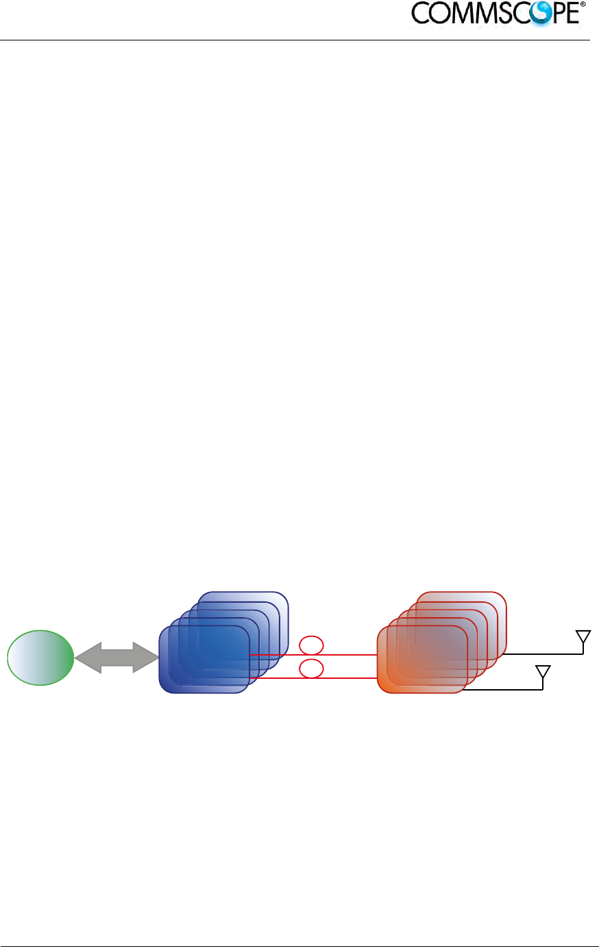
The system has two basic components, a Master Unit and a Remote Unit. The
Master Unit is made of one or more subracks typically connected to the BTS (Base
Transceiver Station) through either a repeater (RF interface) or a coaxial cable.
Each Remote Unit is connected with a dedicated pair of single-mode optical fibres
(one for UL and one for DL) to the Master Unit. These optical fibres work on 1310 nm
wavelength and provide low losses and almost unlimited bandwidth, available for
future system developments.
Figure 2-1 ION-B System Block Diagram
BTS
RF Interface
TFLN Remote
Unit

User’s Manual for ION-B Systems
Page 22 ION-B User Manual (MN024-15)_n_20150730.docx
ION-B is a modular system whose basic components are:
one Master Unit made of one or more subracks, each providing 12 module slots.
Each slot can host either an active or a RF passive device (chosen among the
wide range of ION-B options), in order to meet the planned design requirements;
a variable number of Remote Units (TFAx), whose function is feeding the antenna
passive network;
a proper number of indoor antennas, suitable to provide radio coverage to the
area. ION-B is fully compatible with any type of indoor antennas;
the optical cables required to connect the 19” subracks to the TFAx.
2.3. ION-B FEATURES
The following lines report a brief summary of ION-B main features:
multiband 2G, 2.5G, 3G, and 4G compatible: ION-B is completely transparent to
any transmission protocol and modulation format, and it can distribute any 2G,
2.5G, 3G, and 4G wireless standard. In addition, it allows to carry also the WLAN
(802.11b/g) service over the same infrastructure;
modular configuration for flexible design: by properly setting some parameters like
the amount of RUs and the antenna locations, the ION-B architecture can follow
the environment specific features in order to obtain the most effective radio-
coverage of the indoor area. The modularity of the system allows easy
modifications for future growth and increasing traffic;
easy to install: the intelligent plug & play ION-B system includes an Automatic
Gain Control (AGC), that eliminates system gain variations regardless of optical
loss. This avoids the need for field adjustments, thus reducing design, installation
and optimization time.
low-power consumption: establishing a “quasi line-of-sight propagation” towards all
mobile phones inside the area, ION-B works with low power levels. Low power
levels have two great advantages: 1) allow mobile phones to work at lower power
levels, thus limiting the radiated emissions and increasing their battery life; 2) allow
a better control of interference effects between adiacent cells.
central supervision functions: all individual alarms of ION-B system are available to
both local and remote connections. Detailed alarm information is provided by
special software (i.e. by Supervision or Maintenance software tools) running on a
locally connected host, as well as any information about alarm status and alarm
history is available to remote connections via TCP/IP protocols, SNMP agent, or
HTTP servers. This alarm information is visible also by means of LEDs present on
the front panels of both the MU and the RUs;
multiple-carriers system: there are no restrictions on the number of carriers that
the ION-B can convey. Obviously, the more carriers per service, the less power
per carrier;
remote power supply: in case mains cannot be used for the Remote Units, ION-B
offers a centralised power supply option, which distributes both a DC low-voltage
(-48V) power and the optical signals through a composite fibre optic/copper cable;

User’s Manual for ION-B Systems
ION-B User Manual (MN024-
15)_n_20150730.docx Page 23
wide variety of RF passive devices: the connections between the DAS and the
local BTSs are able to be arranged so as to get the best fit for the customers
needs. ION-B equipment provides RF splitters/combiners, cross band couplers,
attenuators, and duplexers for UL/DL paths, thus allowing maximum in design
flexibility;
high reliability: high MTBF (Mean Time Between Failure).
2.4. TYPICAL ION-B APPLICATIONS
Due to its unique features, the ION-B is an ideal solution for radio coverage in a
variety of situations:
Multi-operator shared infrastructures: each mobile operator has its own carrier which
needs to be transported without interfering with the others. The ION-B is capable of
transmitting multiple carriers simultaneously while providing independent level
adjustments for each of them, ensuring maximum performance and reducing
infrastructure costs.
High rise buildings: RF signals from surrounding macrocells or external BTSs are
usually quite strong inside high rise buildings and can cause so much interference
that indoor mobile communications often become impossible. By strategically placing
antennas along the exterior walls of the building, the signal to noise ratio can be
optimized. This interference control solves many problems, such as the “ping pong”
effect that sometimes is experienced when a mobile frequently changes from indoor
to outdoor coverage.
Exhibitions, conventions, and shopping centers: the critical aspect of these
environments is their high traffic loads, which are furthermore also highly variable.
Thus, the main goal in these cases is to set up radio coverage enabling the effective
management of these variable traffic loads, with neither undervalued nor overvalued
infrastructure expenses. A unique feature of the ION-B is that RF frequencies can be
allocated quickly when and where they are needed, thus reducing implementation
costs. This makes the ION-B an ideal solution for temporary or last minute requests
(such as conferences).
Airports: require both modular and flexible radio coverage in order to meet their
current needs while also foreseeing future expansions. The ION-B is able to manage
heavy traffic loads, providing a high level of quality with minimum environmental
impacts, its modularity also allows for future expansions.
Corporate buildings: inside a corporate building, frequent disruptions during mobile
communications may limit business transactions. These environments are often
complex and densely populated while having specific requirements: heavy traffic
capacity, high expectations regarding quality of service, full compatibility with
wireless standards and future expandability. The ION-B guarantees high quality radio
coverage in all of the above conditions and maintains maximum flexibility while
managing any possible traffic conditions.
Subways and densely populated metropolitan areas: These areas are distinguished
by large surface areas, and may require RUs to be placed far away from the BTSs.
The ION-B guarantees signal integrity for distances up to 3km, while through the
wideband interconnect link option, distances of 20km can be reached. Moreover,

User’s Manual for ION-B Systems
Page 24 ION-B User Manual (MN024-15)_n_20150730.docx
these environments require gradual investments, because initially operators tend to
provide radio coverage only in the busiest areas, and then extend it in order to reach
complete coverage later.
The modularity of the ION-B helps operators to gradually expand the system. Often,
large cities set up seamless and reliable radio systems for emergency services. In
these cases, the required RF infrastructure needs to be unobtrusive and
environmental friendly; this can be achieved using an ION-B DAS. When redundancy
is required, two interleaved ION-B systems can be used, management and
supervision for these systems can be remotely established by means of an external
modem and an open protocol such as SNMP.
User’s Manual for ION-B Systems
ION-B User Manual (MN024-
15)_n_20150730.docx Page 25
3. EQUIPMENT OVERVIEW
3.1. INTRODUCTION
The basic components of an ION-B system are the following:
a Master Unit, able to bring the mobile signals from the BTS to
different Remote Units and vice-versa, thus remotising the distribution
and collection of any mobile signals via fiberoptic cables;
a variable number of Remote Units, conveying and receiving mobile
signals through low-power antennas.
A brief introduction to the main components of the ION-B system’s Master and
Remote Units is presented in the following section. The details of each component
can be found in the subsequent sections of this manual.
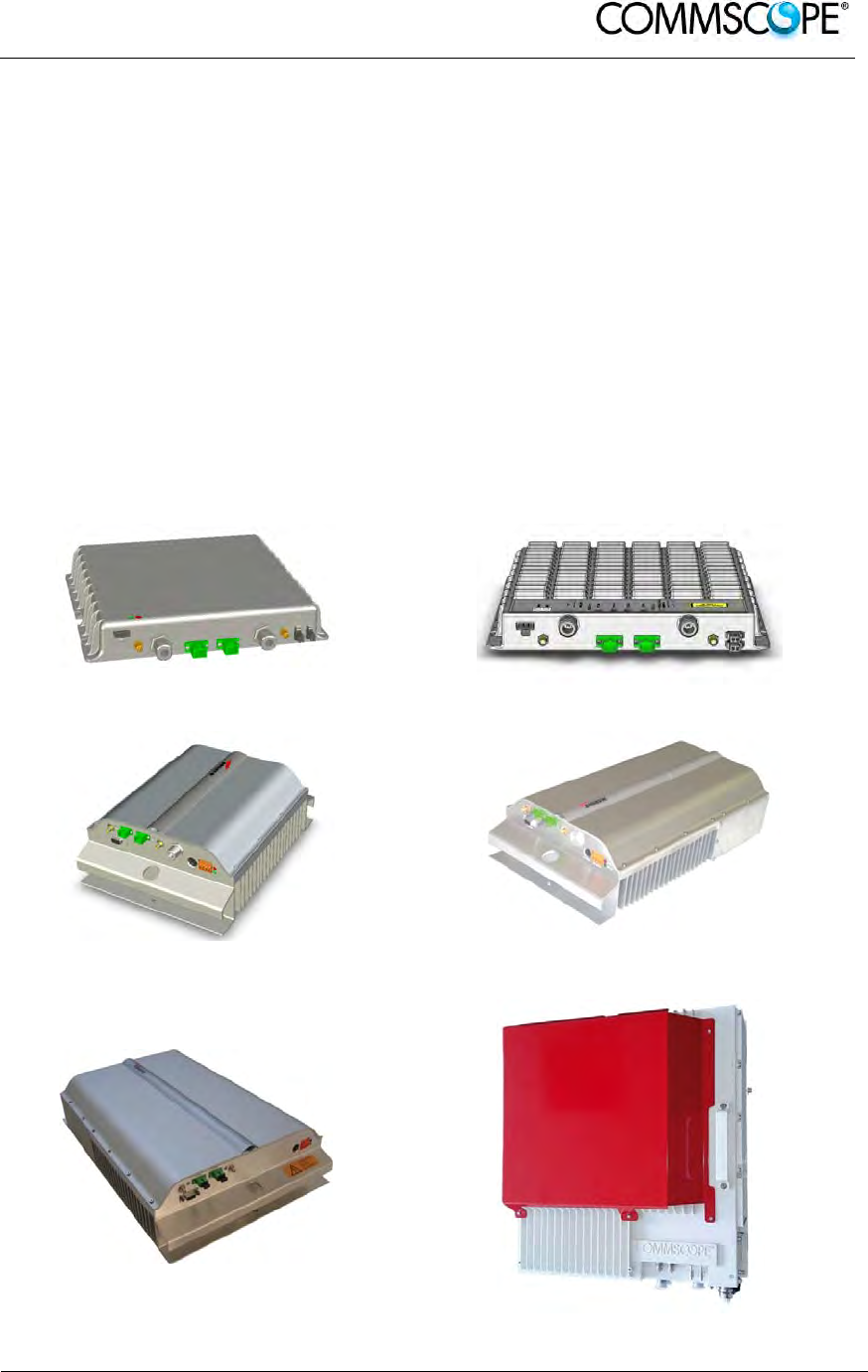
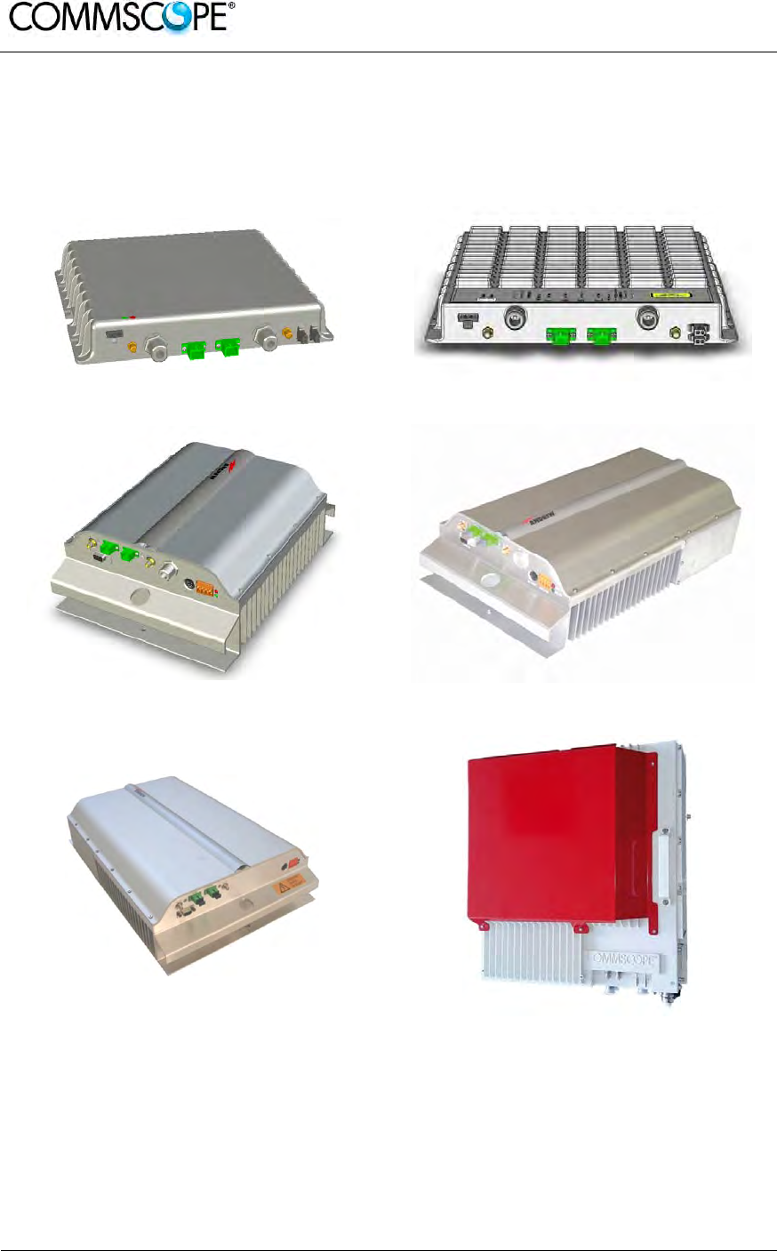
3.2. THE ION-B REMOTE UNIT AND ITS RELEVANT ACCESSORIES
Figure 3-1 Case A Remote Unit Figure 3-2 Case B Remote Unit
Figure 3-3 Case R2 Remote Unit Figure 3-4 Case-R2E Remote Unit

User’s Manual for ION-B Systems
Page 26 ION-B User Manual (MN024-15)_n_20150730.docx
Figure 3-5 Case-R4E Remote Unit Figure 3-6 Case-U Remote Unit
The Remote Unit (TFAx) is a device which provides optical-to-electrical downlink
conversion and electrical-to-optical uplink conversion, thus allowing a bidirectional
transmission of signals between the Master Unit and the remote antennas. It is
available in 3 different power configurations (Low/Medium/High), housed by 5
different architectures (Case A, Case B, Case R2, Case R2E, Case R4E, and Case
U), so as to fulfill different coverage and band requirements.
In downlink, each TFAx receives an optical signal from the Master Unit, performs an
optical-to-RF conversion, and transmits the resulting signal to the antenna ports.
In uplink, it receives an RF signal from the remote antennas, provides an RF-to-
optical conversion, and conveys the converted signal to the Master Unit through
optical fibers.
The ION-B Remote Units are available both with power supply 90÷264 Vac and with
power supply -60÷-36 Vdc. Each ION-B Remote Unit is provided with a suitable
internal or external power adapter.
Last, each ION-B Remote Unit has a wideband auxiliary channel, which can be
exploited for dedicated RF distribution through external boosters.

User’s Manual for ION-B Systems
ION-B User Manual (MN024-
15)_n_20150730.docx Page 27
Remote Units, Boosters and Accessories
Unit name/
Module name
Description
Dimensions (L x W x H)
TFAx-case A
TFAx Case B
TFAx Case R2
TFAx Case R2E
TFAx Case R4E
TFAx Case U
TFBx case B
TFBx case R2
TFBx Case U
TKA04
TPSN 1/05-40
TPSN 3/05-30
TPSN 1/28-80
TPSN 1/32-80
TPSN 3/28-80
TPSN 3/32-80
TPSN 1/28-120
TPSN 3/28-100
TPSN1/28-150
TPSN3/28-130
Remote Unit
Remote Unit
Remote Unit
Remote Unit
Remote Unit
Remote Unit (incl. connectors)
Booster
Booster
Booster
Remote Unit installation kit
External power supply
External power supply
External power supply
External power supply
External power supply
External power supply
External power supply
External power supply
External power supply
External power supply
200 x 240 x 38 (mm)
240 x 240 x 38 (mm)
330 x 250 x 122.5 (mm)
513 x 250 x 125 (mm)
515 x 335 x 125 (mm)
514 x 480 x 205 (mm)
240 x 240 x 38 (mm)
330 x 250 x 122.5 (mm)
514 x 480 x 205 (mm)
340 x 240 x 55 (mm)
175 x 80 x 54 (mm)
175 x 80 x 51 (mm)
168 x 78 x 46 (mm)
168 x 78 x 46 (mm)
168 x 78 x 46 (mm)
168 x 78 x 46 (mm)
160 x 76 x 47 (mm)
175 x 80 x 51 (mm)
228 x 68 x 39 (mm)
175 x 80 x 150 (mm)
table 3-1 Different Cases of ION-B Units, with dedicated ION-B accessories
User’s Manual for ION-B Systems
Page 28 ION-B User Manual (MN024-15)_n_20150730.docx
3.3. THE ION-B MASTER UNIT
The ION-B Master Unit is a widely-flexible system. Its modular feature allows it to be
developed both for simple installation-friendly, unobtrusive applications to complex
installations, involving a virtually unlimited number of subracks, and distributed
through several floors of a building or through a 20km distance.
The following text presents a brief overview of the components of these units.
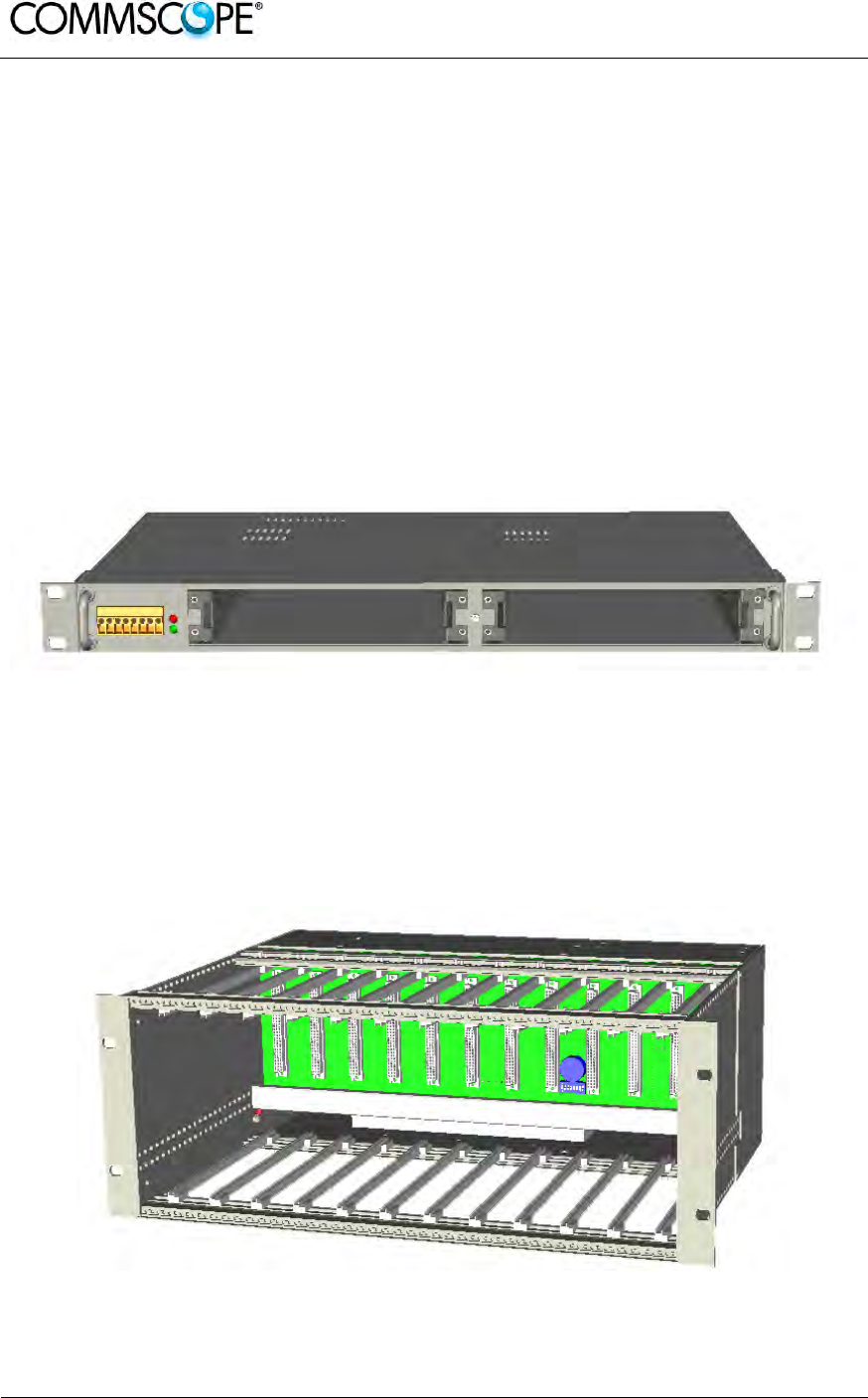
The TPRF31 Fast MiniRack is a 19” x 1HE fast-MiniRack housing 2 slots: it can
therefore accommodate 2 of the single-slots (7TE x 4HE) ION-B cards presented in
the following. Thanks to its turnable brackets, the TPRF31 is suitable both for wall
and rack-mounting, and can therefore be used both as a stand-alone unit (for simple
ION-B installations) and as an integration of a bigger and more complex ION-B
system.
Figure 3-7 TPRF32 Minirack
The TPRN sub-rack is a 19”x 4HE subrack with 12 slots, each one sized 7TE x 4HE.
As each ION-B module takes up one or two slots, each Master Unit can host up to 12
modules, depending on the design configuration and requirements.
Figure 3-8 TPRN Subrack
User’s Manual for ION-B Systems
ION-B User Manual (MN024-
15)_n_20150730.docx Page 29
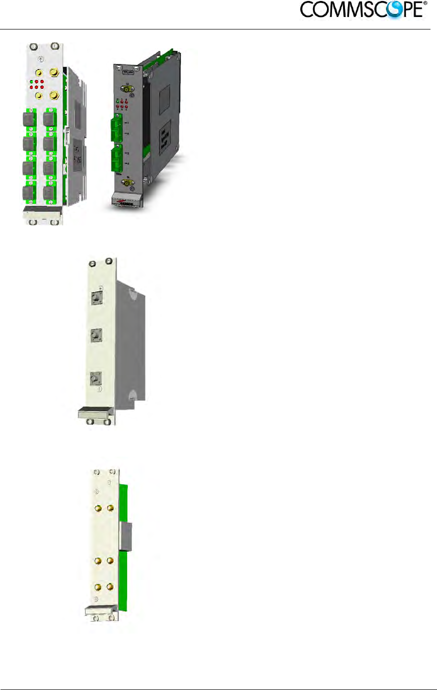
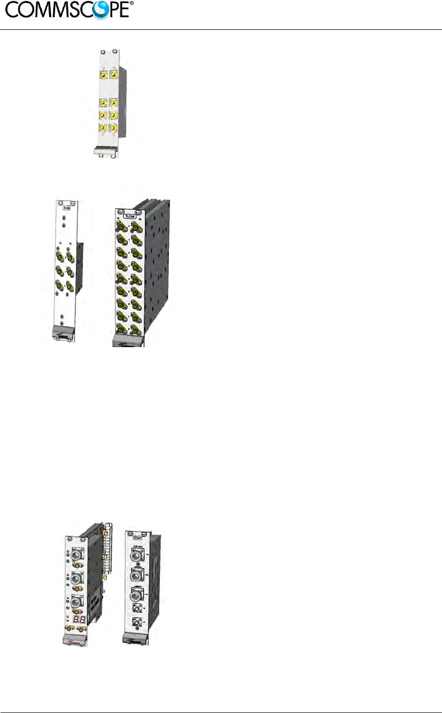
The Master Optical TRX (TFLN or
TFLNW): in downlink, it provides an RF-
to-optical conversion of the signal coming
from the BTS, and transmits it to 4 optical
outputs, so as to feed 4 TFAx (TFLNW: 2
TFAH-EU). In uplink, it provides optical-
to-RF conversion for 4 optical signals
coming from the RUs, and it combines
them into a single RF output, while
providing automatic gain control in order
to balance the fibre losses.
Module dimensions:
Width = 7TE, Height = 4HE
Figure 3-9 TFLN Card
The Duplexer (TDPN): it combines the
downlink (DL) and the uplink (UL)
paths into a single one, while maintaining
the required isolation.
The module dimensions are:
Width = 7TE, Height = 4HE
Figure 3-10 TDPN Card
The dual band coupler (TLDN): in
downlink, it combines a low-band RF
signal (700 to 1000 MHz) and a high-
band RF signal (1700 to 2500 MHz) into
a common RF port; in uplink, it splits a
composite signal between a low-band RF
port and a high-band RF port.
Module dimensions are:
Width = 7 TE, Height = 4 HE.
Figure 3-11 TLDN Card
User’s Manual for ION-B Systems
Page 30 ION-B User Manual (MN024-15)_n_20150730.docx
The tri-band coupler (TLTN): in downlink,
it combines a low-band signal, a middle-
band signal, and a high-band signal into
a communal one; in uplink, it splits the
triple band signal among the three RF
single band paths.
Module dimensions are:
Width = 7 TE, Height = 4 HE.
Figure 3-12 TLTN Card
TLCNx-W is a family of RF
splitters/combiners which can be used in
different situations, such as:
To connect a BTS with several master
optical TRXs. In uplink, the TLCNx-W
combines RF signals which come from
different master optical TRXs into a
common RF signal entering the BTS.
In downlink, the TLCNx-W splits the
composite RF signal which comes
from the BTS into more RF ports,
entering different master optical TRXs.
To connect several BTSs to a master
unit. In downlink, the TLCNx-W
combines the RF signals coming from
different BTSs into a common RF
signal, entering the master unit. In
uplink, the TLCNx-W splits the
composite RF signal coming from the
master unit into more RF signals
entering different BTSs.
Module dimensions are:
Width = 7 TE, Height = 4 HE.
Figure 3-13 TLCN2-W and TLCN8-W
Cards
Figure 3-14 TPOIx and TPOI-Px Cards
TPOIx includes duplexer, digital
adjustable attenuator, downlink automatic
level control (ALC) and cross band
coupler functionalities for triple bands
which allows to feed the master optical
TRX with proper levelling.
TPOI-Px includes duplexer and cross
band coupler functionalities for triple
bands which allows to feed the master
optical TRX.
Module dimensions are:
Width = 7 TE, Height = 4 HE.
User’s Manual for ION-B Systems
ION-B User Manual (MN024-
15)_n_20150730.docx Page 31
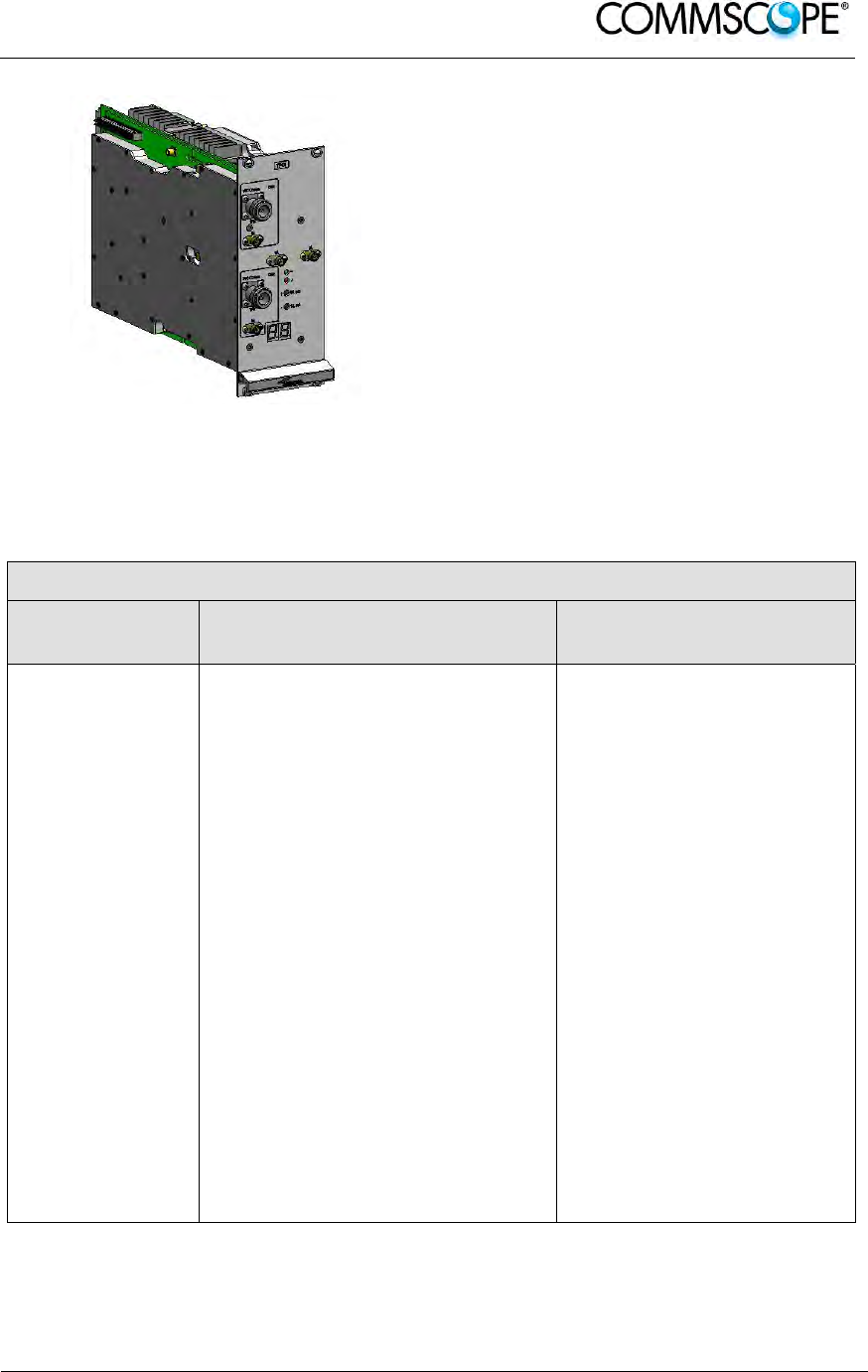
TPOIx/x is an integrated point of interface
which enables MIMO applications. It
includes double IF conversion.
Module dimensions are:
Width = 14 TE, Height = 4 HE.
Figure 3-15 TPOI MIMO Card
An overview of the basic components of the ION-B Master Unit is shown in the
following table.
Basic components of ION-B Master Units
Unit name/
Module name
Description
Dimensions, H x W ( x D)
TPRF31
TPRN04
TPRNx4
TFLNx
TLCN 2-W
TLCN 8-W
TPOIx
TPOIx/x
TPOI-Px
TDPNx
TLDNx
TLTNx
Fast MiniRack
Passive subrack
Active subrack
Master Optical TRX
2-way splitter
8-way splitter/combiner
Point of interface
MIMO Point of interface
Passive point of interface
UL/DL duplexer
Dual band coupler
Tri band coupler
19” x 1HE x 286mm
19” x 4HE x 350mm
19” x 4HE x 350mm
7TE x 4HE
7TE x 4HE
7TE x 4HE
7TE x 4HE
14TE x 4HE
7TE x 4HE
7TE x 4HE
7TE x 4HE
7TE x 4HE
table 3-2 Overview of the Components and Accessories for the ION-B Master Unit
User’s Manual for ION-B Systems
Page 32 ION-B User Manual (MN024-15)_n_20150730.docx
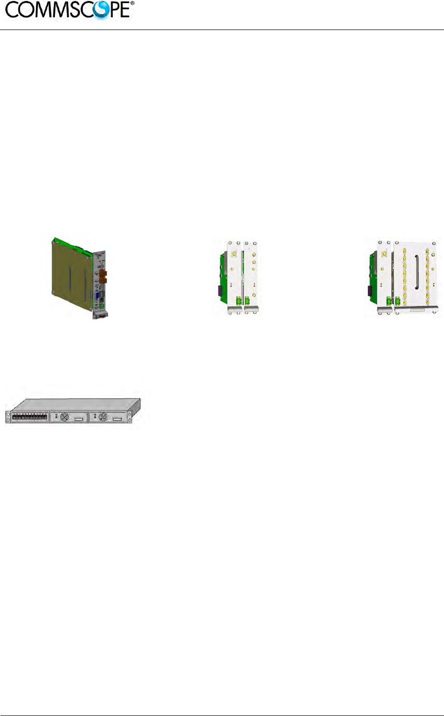
3.4. ION-B ADDITIONAL OPTIONS
The basic ION-B structure described above can be expanded further or supported by
a range of ION-B options, including:
A supervision unit (TSUN), enabling to supervise and manage the ION-B system
through any PC or Laptop, thanks to a web-interface supporting the TCP/IP, FTP,
HTTP, protocols, and fully compatible with general purpose SNMP managers.
A wide range of Interconnect Link options (TIL), i.e. a set of master-slave modules
which enable to expand the ION-B system through additional subrack stations, up
to 20 km away from the main one.
A Remote Powering Unit (TRSN), providing -48Vdc power supplying through
composite fiberoptic/copper cables
Figure 3-16 TSUN
supervision unit, plug-in
card
Figure 3-17 Interconnect-link
master modules Figure 3-18 Interconnect-link
slave modules
Figure 3-19 TRSN Remote
Powering units
We strongly recommend contacting the reference Commscope salesperson or
product line manager for detailed information on the main ION-B additional options.

User’s Manual for ION-B Systems
ION-B User Manual (MN024-
15)_n_20150730.docx Page 33
4. TFAX REMOTE UNIT (RU)
4.1. THE MAIN TASKS OF THE TFAX REMOTE UNIT
Downlink (DL):
• Optical-to-RF conversion of the input optical signal
• Automatic Gain Control (AGC) of each converted signal in order to compensate
optical losses
• RF amplification: the converted RF signal is boosted in order to maintain a good
signal-to-noise ratio
• RF filtering: a proper filter rejects the spurious emissions
• RF duplexing and splitting: the boosted RF signal is conveyed to one or two
antenna ports according to the different versions
Uplink (UL):
• RF amplification: a low noise amplifier boosts the signal received from antennas
in order to maintain a good signal-to-noise ratio
• RF filtering: the boosted signal is cleaned of the spurious emissions
• Automatic Level Control (ALC): the RF signal level is adjusted according to
blocking requirements
• RF-to-optical conversion of the signal, which is finally conveyed to the output
optical port
User’s Manual for ION-B Systems
Page 34 ION-B User Manual (MN024-15)_n_20150730.docx
4.2. DIFFERENT TYPES OF REMOTE UNITS
In order to allow radio coverage with different power and band requirements, the
ION-B architecture provides a wide variety of RUs. This allows to choose the solution
which best fits the individual coverage and environmental demands.
Figure 4-1 Case A Remote Unit Figure 4-2 Case B Remote Unit
Figure 4-3 Case –R2 Remote Unit Figure 4-4 Case R2E Remote Unit
Figure 4-5 Case R4E Remote Unit Figure 4-6 Case-U Remote Unit
Depending on the bands where radio coverage has to be provided and on the signal
power required to cover the environment, the topology / case type of the RU will be
determined.
Please follow the instructions described in the section corresponding to the case type
(A, B, R2, R2E, R4E, and U) of your particular RU.

User’s Manual for ION-B Systems
ION-B User Manual (MN024-
15)_n_20150730.docx Page 35
The case type of your RU can easily be identified through the above figures.
Alternatively, contact your Sales representative or product line manager.
Product Code Case RF Port Power Supply Bulletin Code
Low
Power
TFAN 40 A 2 Internal -
TFAN 50 A 2 Internal PA-101343-EN
TFAN91/18/21 B 2
TPSN1/05-40
TPSN3/05-30 PA-101586-EN
Medium Power
TFAM 21 A 2 TPSN1/05-40
TPSN3/05-30 PA-100592-EN
TFAM 90/21 B 2 TPSN1/05-40
TPSN3/05-30 PA-100582-EN
TFAM 91/21 B 2 TPSN1/05-40
TPSN3/05-30 PA-100583-EN
TFAM 18/21P B 2 TPSN1/32-80
TPSN3/32-80 PA-102128-EN
TFAM 91/18/21 R2 1 TPSN1/28-80
TPSN3/28-80 PA-101508-EN
TFAM 80/19 B 2 TPSN1/05-40
TPSN3/05-30 PA-100801-EN
TFAM 85/19 B 2 TPSN1/05-40
TPSN3/05-30 PA-100805-EN
TFAM 17/19 B 2 TPSN1/05-40
TPSN3/05-30 PA-101848-EN
TFAM 85/18 B 2 TPSN1/05-40
TPSN3/05-30 PA-100808-EN
TFAM 85/21 B 2 TPSN1/05-40
TPSN3/05-30 PA-100809-EN
TFAM 85/18/21 R2 1 TPSN1/28-80
TPSN3/28-80 PA-102111-EN
TFAM 80/92/19E B 2 TPSN1/05-40
TPSN3/05-30 PA-101058-EN
TFAM 80/92/19EP R2 1 TPSN1/28-80
TPSN3/28-80 PA-102127-EN
High Power
TFAH-US85/19 R2E 1
TPSN1/28-120
TPSN3/28-100 PA-102509-EN
TFAH-US6B R2E 1
TPSN1/28-120
TPSN3/28-100 PA-103140-EN
TFAH-US7B R4E 1
TPSN1/28-150
TPSN3/28-130 PA-104389-EN
TFAH-EU 26/26 R2 2 TPSN1/28-150
TPSN3/28-130 see Commscope
e-catalo
g
TFAH-ES70/80 U 1 Internal
see Commscope
e-catalog
TFAH-ES70/80/50 U 1 Internal
table 4-1 Remote Unit Reference Table

User’s Manual for ION-B Systems
Page 36 ION-B User Manual (MN024-15)_n_20150730.docx
4.3. WARNINGS (TO BE READ BEFORE REMOTE UNITS ARE INSTALLED)
The warnings listed below refer to all RUs. Please read them carefully before starting
the installation.
4.3.1. Dealing with optical output ports
TFAx RUs contain semiconductor lasers. Invisible laser beams may be emitted from
the optical output ports. Do not look towards the optical ports while equipment is
switched on.
4.3.2. Choosing a Proper Installation Site for the RU
• TFAx RUs have to be installed as close as possible to the radiating antennas,
in order to minimize coaxial cable length, thus reducing downlink power loss
and uplink noise figures.
• When positioning the TFAx RU, be sure to place related antennas in such a
way as to minimize the minimum coupling loss (MCL), in order to avoid
blocking.
• The TFAx RU is designed to be fastened to walls, ceilings, or other flat
surfaces (TKA installation kits are available, they provide a protective cover for
the TFAx Remote Unit, while making installation easier and faster).
• It is advisable mounting TFAx RU with optical connectors downwards to safe
the optical connectors from improper dirt.
4.3.3. Handling Optical Connections
• When inserting an optical connector, take care to handle it in a way that the
optical fibre is not damaged. Optical fibres have to be single-mode (SM)
9.5/125μm.
• Typically, ION-B equipment is provided with SC-APC optical connectors (other
connectors are provided upon request). Inserting any other connectors will
result in severe damage.
• Do not force or stretch the fibre pigtail with curvature radius of less than 5cm.
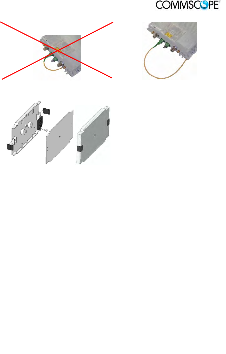
See Figure 4-7 Wrong handling of optical connections with ION-B RUs and
Figure 4-8 Correct handling of optical connections with ION-B RUs for optimal
fibre cabling.
• Remove the adapter caps only just before making connections. Do not leave
any SC-APC adapters open, as they attract dirt. Unused optical connectors
must always be covered with their caps.
• Do not touch the connector tip. Clean it with suitable material before inserting
each connector into its sleeve. If connector tips require cleaning, use only pure
ethyl alcohol.
User’s Manual for ION-B Systems
ION-B User Manual (MN024-
15)_n_20150730.docx Page 37
Figure 4-7 Wrong handling of optical
connections with ION-B RUs Figure 4-8 Correct handling of optical
connections with ION-B RUs
Figure 4-9 Splice box open/closed
4.3.4. Antenna Connections - Connectors
For mounting the cable connectors, it is recommended to refer to the corresponding
documentation of the connector manufacturer. The bending radius of the cables must
remain within the given specifications.
For the selection of RF cables, it should be considered that, on the one hand, a cable
with higher loss is less expensive but, on the other hand, it impairs performance.
Notice: Use an appropriate torque wrench for the coupling torques:
- for N-type connectors (2 N-m / 20 in lb) with 13/16 in opening,
e. g. item no. 244379 available from the CommScope e-catalog
- for 7/16 DIN-type (25 N-m / 19 ft lb) with 1 ¼ in opening,
e. g. item no. 244377 available from the CommScope e-catalog
- for 4.3-10 type connectors (5 N-m, 44 in lb) with 22 mm (7/8) in
opening
Do NOT use your hands or any other tool (e.g. a pair of pliers). This might
cause damage to the connector and lead to a malfunction of the
Extension Unit.

User’s Manual for ION-B Systems
Page 38 ION-B User Manual (MN024-15)_n_20150730.docx
Attention: To minimize passive inter-modulation (PIM) distortion, attention has to be
paid to the physical condition of the connector junctions:
Do not use connectors that show signs of corrosion on the metal surface.
Prevent the ingress of water or dirt into the connector.
Use protective caps for the connectors when not mounted.
Before mounting clean the connectors with dry compressed air.
Before mounting clean the mating surfaces of the connector with a lint-free
alcohol-drenched cloth on a wooden or non-metallic item.
Attach and torque the connectors properly.
Avoid metallic abrasion when mounting the connectors by only screwing the
connecting nut, but not turning the whole connector.
Use a torque wrench to fasten the connector, see above.
Clean the protective caps before mounting for antenna cable replacement.
4.3.5. Cleaning Procedure for RF Cable Connectors
1. What is needed for the cleaning?
a. Isopropyl alcohol
b. Compressed air
c. Lint-free wipe
d. Cotton buds
2. Remove protective cap from the RF
connector.

User’s Manual for ION-B Systems
ION-B User Manual (MN024-
15)_n_20150730.docx Page 39
3. Remove metal chips and small
particles from the mating and inner
surfaces of the connector using
compressed air.
4. Clean the connector winding with lint-
free wipe drenched with isopropyl
alcohol.
5. Clean the lip of the inner ring with
lint-free wipe drenched with isopropyl
alcohol.
6. Clean the inside surface of the inner
ring with lint-free wipe drenched with
isopropyl alcohol.
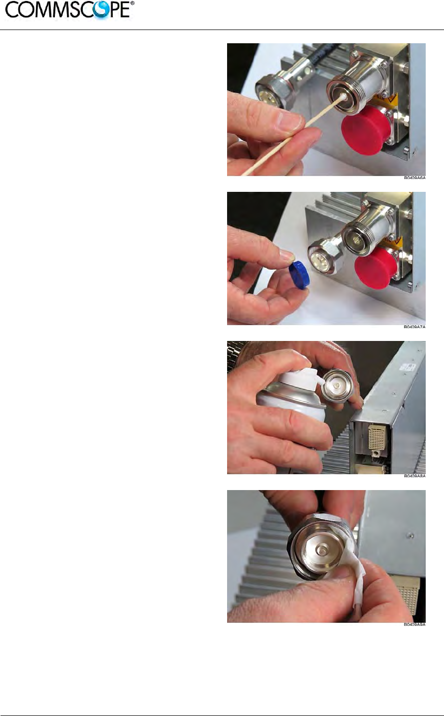
User’s Manual for ION-B Systems
Page 40 ION-B User Manual (MN024-15)_n_20150730.docx
7. Clean the inside of the center
conductor spring tines with a cotton
bud drenched with isopropyl alcohol.
8. Clean in the similar way the
connector of the connected cable.
Remove protective caps from the unit
connector first.
9. Remove metal chips and small
particles from the mating and inner
surfaces of the connector using
compressed air.
10. Continue with the winding area using
lint-free wipe drenched with isopropyl
alcohol.

User’s Manual for ION-B Systems
ION-B User Manual (MN024-
15)_n_20150730.docx Page 41
11. Continue with the inside mating
surface of the inner ring.
12. Clean the outside surface of the
center pin.
4.3.6. Antenna Cable Connector Assembly
1. What is needed for the connector
assembly?
a. Torque wrench.
b. (Adjustable) counter
wrench
2. Join the connectors and turn the
coupling nut until the thread grips.
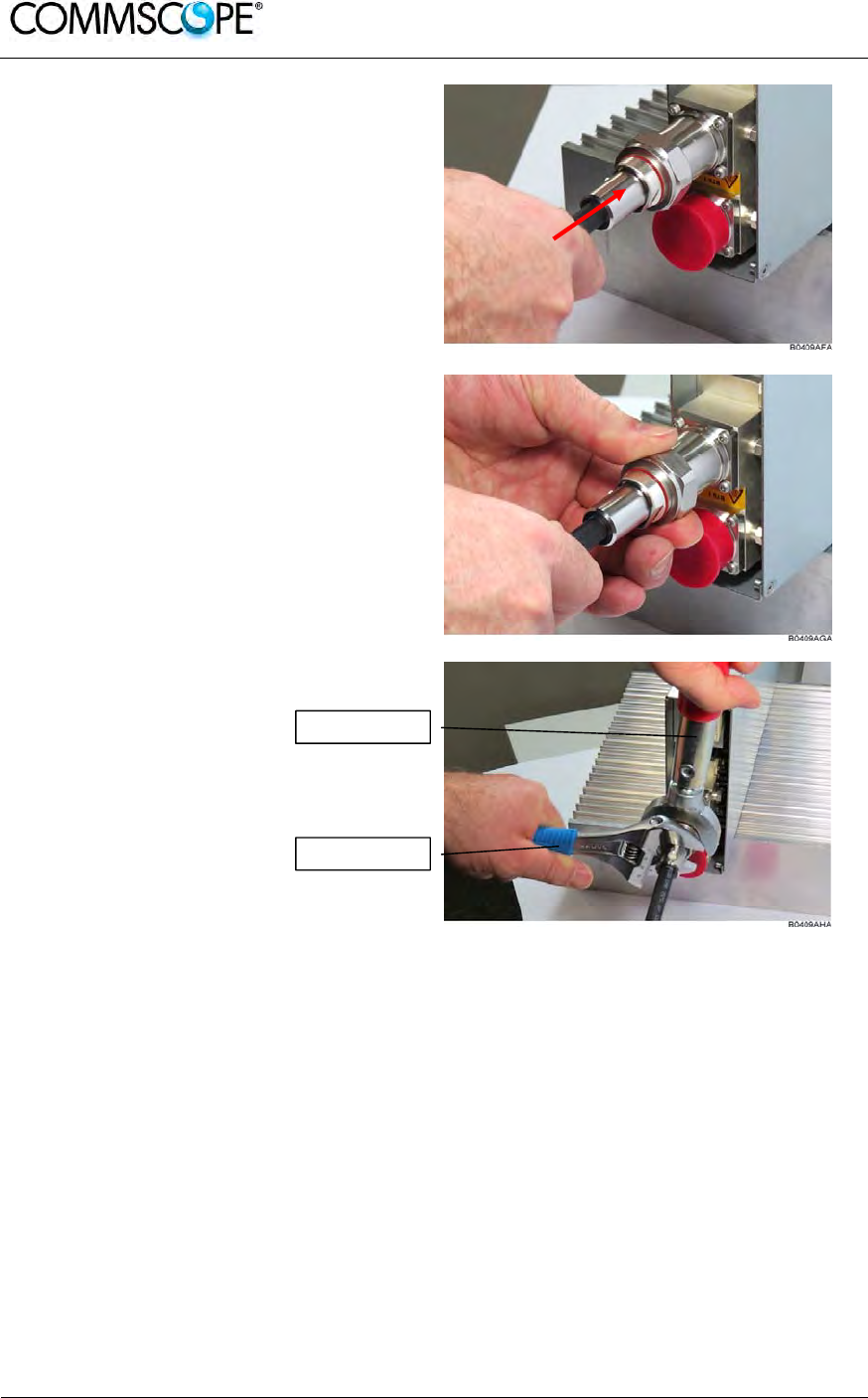
User’s Manual for ION-B Systems
Page 42 ION-B User Manual (MN024-15)_n_20150730.docx
3. Push in the connector until it clicks.
4. Fasten the coupling nut hand-tight. Do
not turn the connector but the coupling
nut only.
5. Retain the cable connector with the
counter wrench and fasten the
coupling nut with the
torque wrench until the torque is
applied (torque wrench clicks).
For angled antenna connectors use your hand to retain the cable connector and
fasten the coupling nut with the torque wrench. Make sure only the coupling nut is
turned, not the cable connector.
Torque wrench
Counter wrench
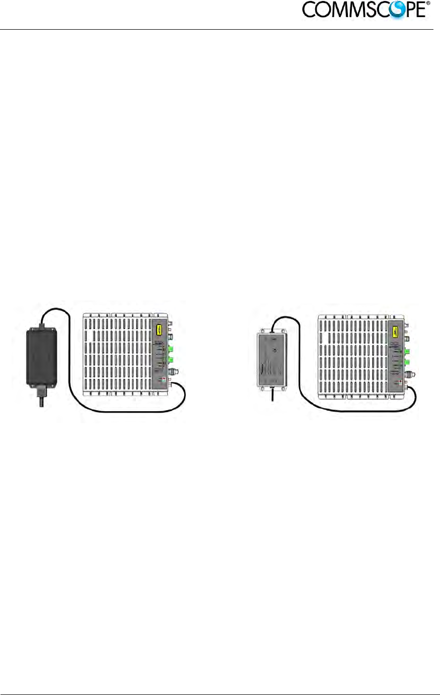
User’s Manual for ION-B Systems
ION-B User Manual (MN024-
15)_n_20150730.docx Page 43
4.3.7. Correct Positioning of the Remote Unit and its Power Supply
• Under no circumstances should any component be affected by the heat
created by any other one. The RU and its external power supply should be
mounted so as to avoid reciprocal heating. Side-by-side configuration is
suggested (see Figure 4-10 90/264 VAC power supply, case B and Figure
4-11 -48 VDC power supply, case B).
• RUs are provided with cooling fins which allow the optimization of heat
dissipation. To ensure proper operation the mounting environment should
allow for the necessary air flow.
• It is strongly recommended not to mount the external power supply on a
horizontal surface because this position does not allow heat dissipation.
External power supplies must be mounted on vertical surfaces.
• In order to assure proper heat dissipation, external power supplies must be
mounted in a vertical position with the power socket downwards (examples for
proper mounting to ensure proper heat dissipation are shown in Figure 4-10
90/264 VAC power supply, case B and Figure 4-11 -48 VDC power supply,
case B).
Figure 4-10 90/264 VAC power supply, case
B Figure 4-11 -48 VDC power supply, case B
Note that the RU and its power supply adapter are mounted side-by-side, and the
power supply adapter has the socket downwards.
4.3.8. Power Supply
The TFAx RU are provided with different types of TPSN external power supplies,
available either for universal mains (90 to 264 Vac) or for negative supply (-60 to -36
Vdc). TPSN external power supplies provide the RUs with either +5Vdc power (by
means of a 3-pole connector, or with +28Vdc/+32Vdc power by means of a shielded
circular connector. Different power ranges are available, see in table 4-1 Remote Unit
Reference Table.
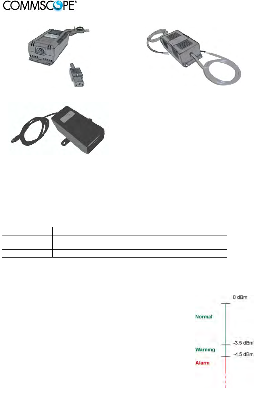
User’s Manual for ION-B Systems
Page 44 ION-B User Manual (MN024-15)_n_20150730.docx
Figure 4-12 220 Vac/+5Vdc power adapter Figure 4-13 -48 Vdc/+5Vdc power adapter
Figure 4-14 220 Vac/+28Vdc power adapter
4.3.9. Visual Alarms
Two control LEDs are provided on the TFAx front side. The green LED indicates the
power supply status, while the red LED indicates any major Remote Unit failures
(please refer to the respective troubleshooting section).
LED colour Meaning
Red Low optical power at DL input and/or RF amplifier failure
Green Power supply OK
table 4-2 Status and Alarm LED Indication
4.3.10. Automatic Gain Control (AGC)
Each RU is provided with an AGC system, which is able to compensate optical
losses when these are estimated to be <3 dB. In case optical
losses are >3.5dB, the LMT application and the ION-B
supervision unit will display a “Warning” alarm: the whole
system still works, but AGC is near to its borderline levels. The
red LED switches on when the estimated optical losses are >4.5
dB; the AGC is no longer able to compensate these losses. As
shown in the previous table, the red LED switches on to indicate
any major failures.
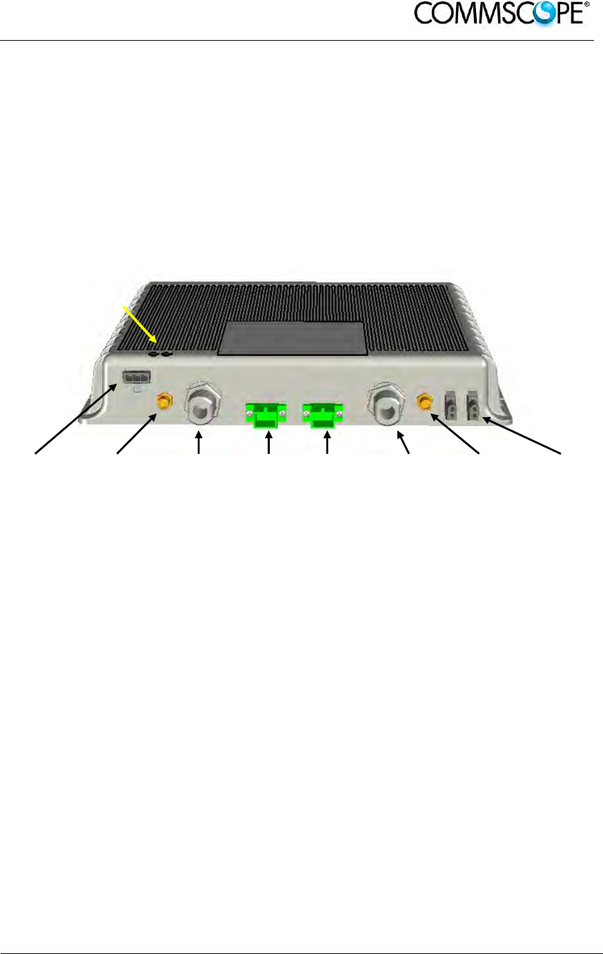
User’s Manual for ION-B Systems
ION-B User Manual (MN024-
15)_n_20150730.docx Page 45
4.4. CASE A REMOTE UNIT
4.4.1. Specifications
Dimensions: 38 x 240 x 200 mm
(1.5 x 9.4 x 7.9 inches)
Weight: Please refer to the RU dedicated bulletin in order to discover any
updated data regarding the weight of a specific Case A RU.
Power
supply
connector
RF auxiliary
DL channel
output
RF
antenna
port DL
DL Optical
port UL optical
port RF
antenna
port UL
RF auxiliary
UL channel
input
External
alarm
connection
Figure 4-15 TFAx Case A RU
RF ports
• 2 RF antenna ports, transmitting/receiving signals to/from distributed
antennas. RF antenna ports are duplexed N-female connectors. These RF
ports can be connected to the antennas either directly (i.e. through RF jumper
cables) or through splitters, thus allowing more antennas to be fed. Unused
RF ports have to be terminated with a 50 Ω load.
• 1 RF auxiliary input and 1 RF auxiliary output (designed to receive and
transmit additional signals). Auxiliary input and output ports are SMA-female
connectors.
Optical ports
• 1 optical output port, transmitting UL signals to TFLN master optical TRX
• 1 optical input port, receiving DL signals from TFLN master optical TRX
Alarm Relay Inputs
The TFAx is provided with two alarm relay inputs which can be connected (through
.062” MOLEX plugs) to any external device (i.e. an external booster). The alarm
information regarding this external device can be signalled through the red LED of
the TFAx LED panel and displayed on the Supervision System.
LED alerts
Green = power ON;
Red = major alarm
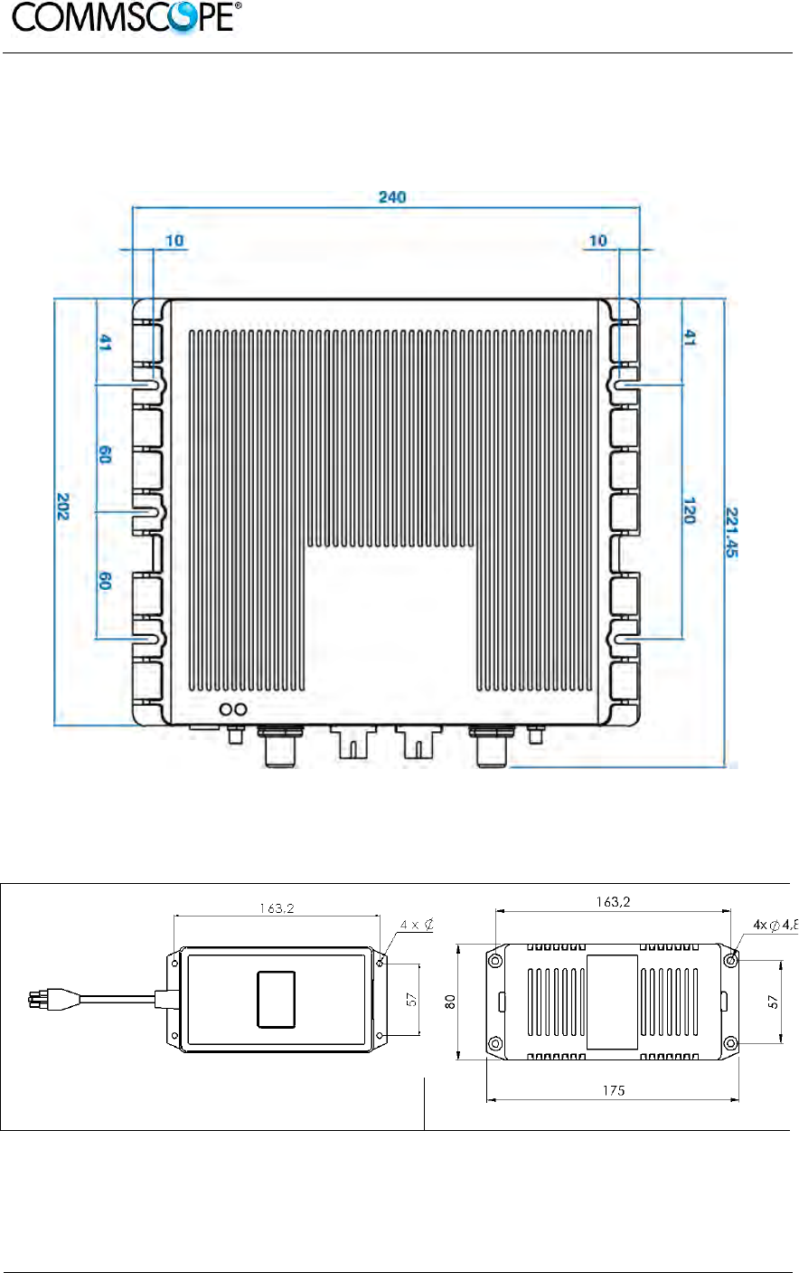
User’s Manual for ION-B Systems
Page 46 ION-B User Manual (MN024-15)_n_20150730.docx
4.4.2. TFAx Case A Installation
The Case A Remote Unit can be mounted to walls or other flat surfaces, either
directly or through a TKA04 installation kit (optional).
Figure 4-16 Case A layout with dimensions
Figure 4-17 Layout of the power adapters with dimensions

User’s Manual for ION-B Systems
ION-B User Manual (MN024-
15)_n_20150730.docx Page 47
4.4.3. Installing a Case A Remote Unit WITHOUT the TKA kit
The TFAx kit includes:
1. a RU TFAx
2. a TPSN external power supply adapter (if applicable)
3. a power supply plug
Once you have choosen a location for the RU, please follow these instructions:
1. In order to install the M4 dowels (not included) which hold up the TFAx
Remote Unit, drill five holes into the wall according to the layout shown in
Figure 4-16 Case A layout with dimensions.
2. Mount the TFAx to the wall by firmly fastening the screws.
3. In order to install the M4 dowels (not included) which hold up the power
supply external adapter, drill four holes into the wall according to the layout
of the power supply, shown in Figure 4-17 Layout of the power adapters
with dimensions.
4. Mount the external power supply to the wall by fastening the screws.
5. Fasten the splice holder inside the splice tray (not included), see Figure
4-18 Inside view of the splice tray, with the splice holder positioned
properly.
6. Splice the optical fibres and close the splice tray. While handling the fibres,
be careful not to bend them.
7. Fasten the splice tray beside the RU.
8. Connect the external adapter to the TFAx RU with the proper cable.
9. If the RU is -48 Vdc powered, use the -48 Vdc plug (included) in order to
connect the external adapter to the -48 Vdc supply. If the RU is 90/264
Vac-powered, mount the 90/264 Vac plug (included) onto a power cord (not
included), and use this cable to connect the external adapter to mains.
10. Connect the antenna RF cables to the RF antenna ports. Connect the UL
and DL optical connectors. If the power cable has properly been connected
to the mains, both the green and the red LEDs should turn on. The green
LED will remain lit to indicate that the unit is powered on, while the red LED
will turn off as soon as the master optical TRX is switched on.
11. Once the installation is finished, please follow the Remote Unit Start-up
section in order to carry out a proper system start up.
Figure 4-18 Inside view of the splice tray,
with the splice holder positioned properly Figure 4-19 Splice tray closed
Splice holder
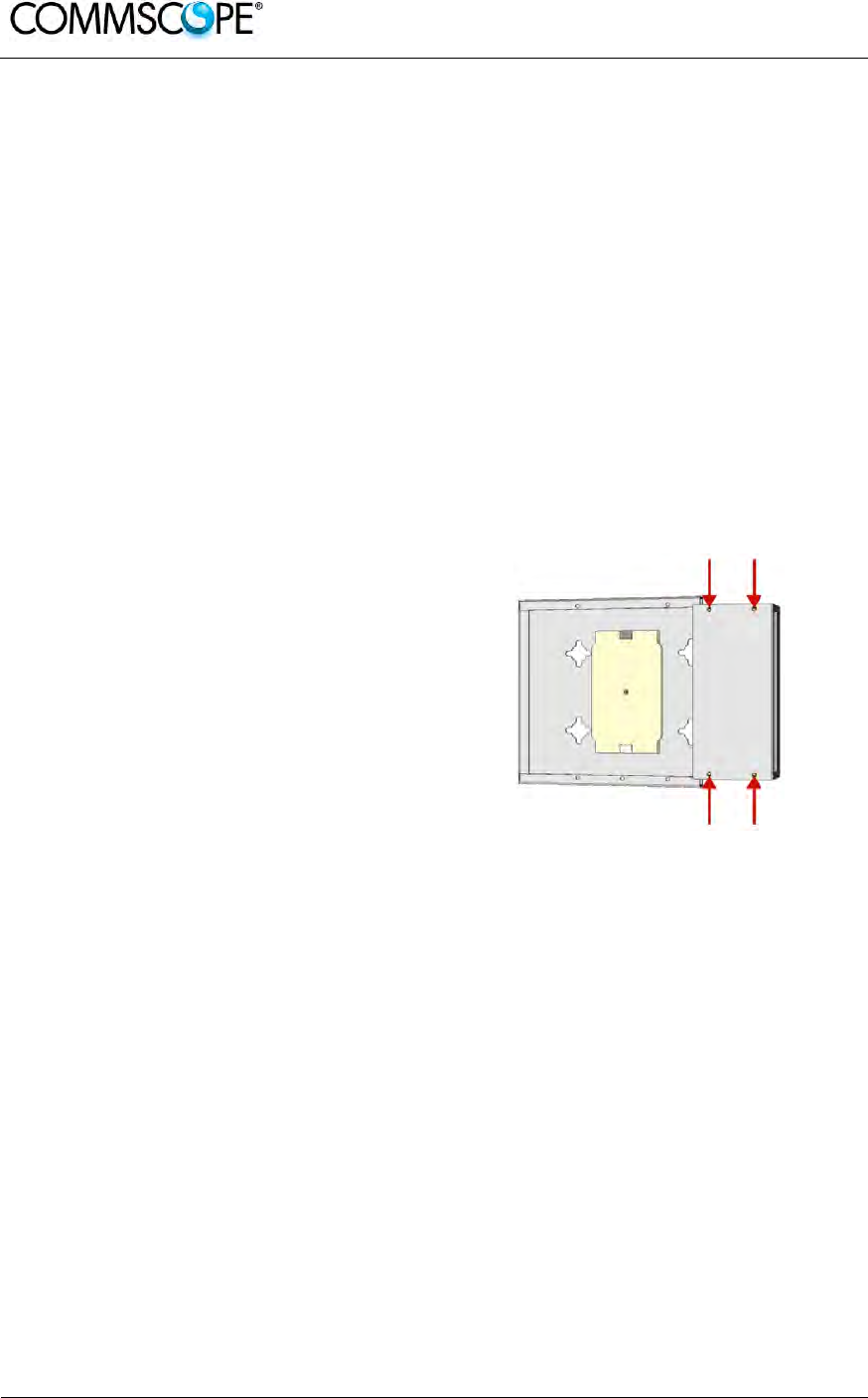
User’s Manual for ION-B Systems
Page 48 ION-B User Manual (MN024-15)_n_20150730.docx
4.4.4. Installation of the Case A Remote Unit WITH the TKA04 Installation Kit
The TFAx Case A kit includes:
1. a RU TFAx
2. a TPSN external power supply adapter (if applicable)
3. a power supply plug
The TKA04 kit includes:
A. four dowels (for fastening the wall bearing to the wall)
B. five dowels (for fastening the TFAx Case A to the wall bearing)
C. a wall mounting box (wall bearing & cover)
D. a splice holder
1. Unscrew the 4 screws which lock
the lower cover of the TKA04 wall
bearing.
Figure 4-20 Dismount TKA cover
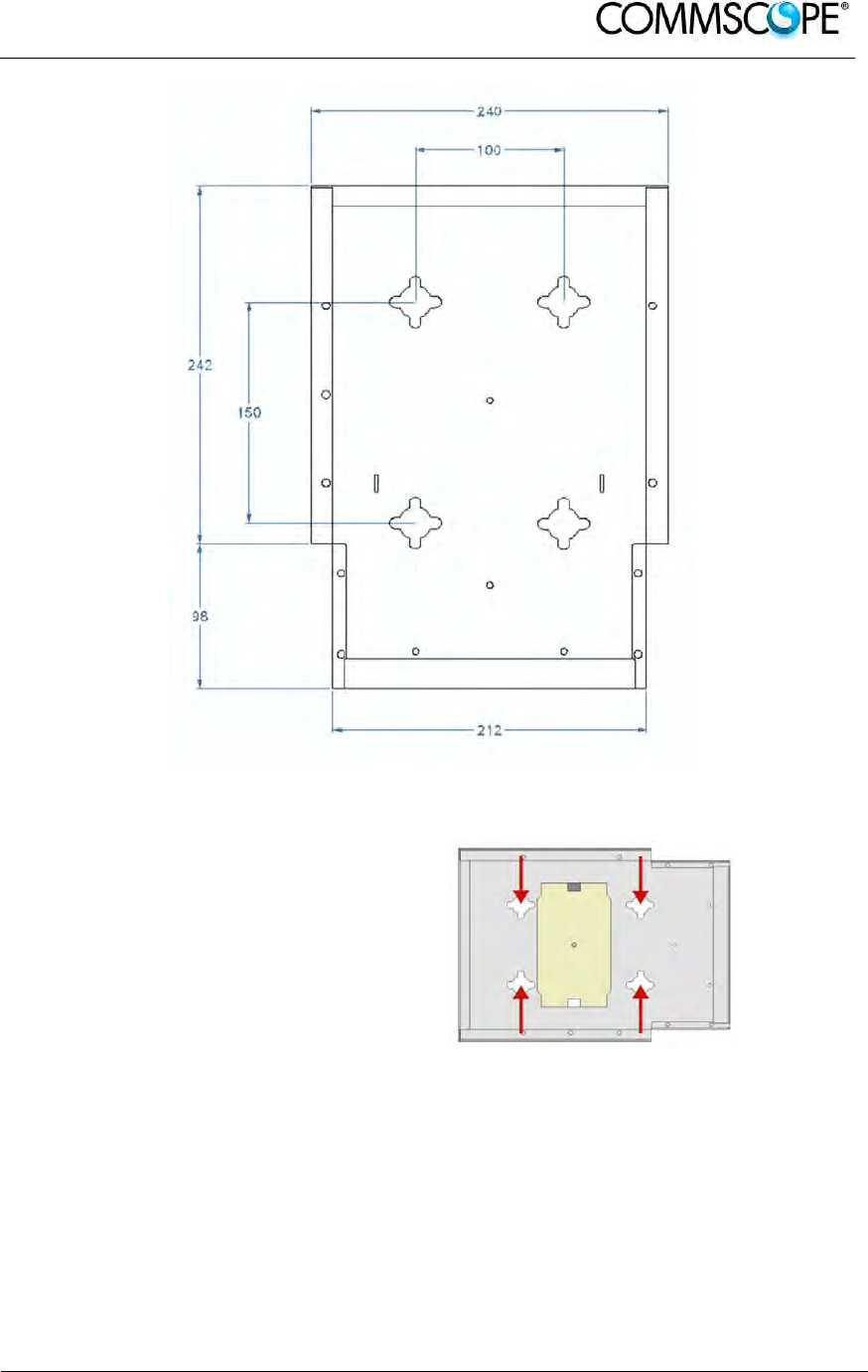
User’s Manual for ION-B Systems
ION-B User Manual (MN024-
15)_n_20150730.docx Page 49
Figure 4-21 Layout of the TKA installation kit for TFAx Remote Unit, Case A
2. In order to install the M4
dowels (included) for the
TKA04 wall bearing, drill
four holes into the wall.
Figure 4-22 Installation: drill four holes
3. Mount the TKA04 wall bearing by firmly fastening the screws.
4. In order to install the M4 dowels (not included) for the power supply external
adapter, drill four holes into the wall according to Figure 4-17 Layout of the
power adapters with dimensions.
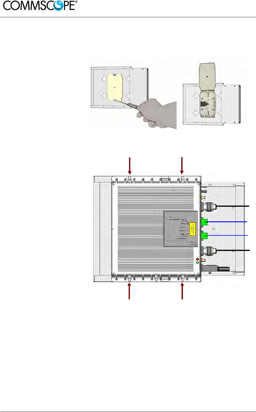
User’s Manual for ION-B Systems
Page 50 ION-B User Manual (MN024-15)_n_20150730.docx
5. Mount the external power supply adapter to the wall by firmly fastening the
screws.
6. Carefully open the
splice tray by using a
screwdriver. Fasten
the splice holder
inside the splice tray.
Splice the optical
fibers and close the
splice tray. While
handling the fibers,
take care not to bend
them. Close the
splice tray.
Figure 4-23 Splice tray
7. Mount the Remote
Unit to the wall-
bearing by using the
included screws.
Figure 4-24 Mount the Remote Unit
8. If the Remote Unit is -48 Vdc powered, use the -48 Vdc plug (included) in
order to connect the external adapter to the -48 Vdc mains. If the Remote Unit
is 90/264 Vac-powered, mount the 90/264 Vac plug (included) onto a power
cord (not included), and use this cable in order to connect the external adapter
to the mains.
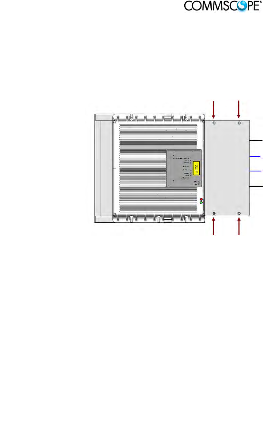
User’s Manual for ION-B Systems
ION-B User Manual (MN024-
15)_n_20150730.docx Page 51
9. Connect the antenna RF cables to the RF antenna ports. Connect the UL and
DL optical connectors. If the power cable has properly been connected to the
mains, both the green and the red LEDs should turn on. The green LED will
remain lit to indicate that the unit is powered on, while the red LED will turn off
as soon as the local unit is switched on (for further details about the start up of
the system, please refer to the Remote Unit Start-up section).
10. Mount the lower
cover by fastening
the four screws.
Figure 4-25 Mount TKA cover
Please note that the figures do not show the mounting of the external power supply
adapter.
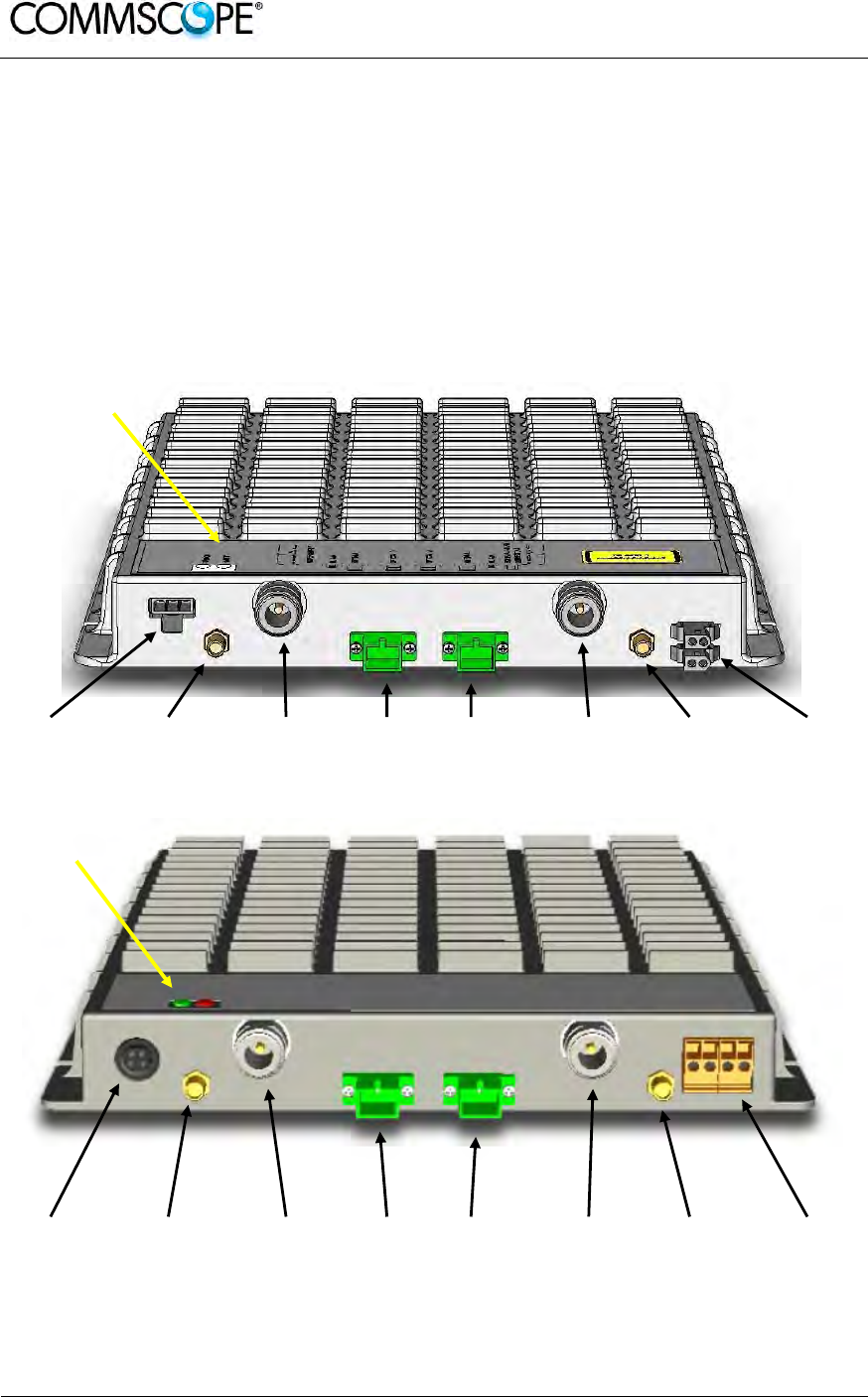
User’s Manual for ION-B Systems
Page 52 ION-B User Manual (MN024-15)_n_20150730.docx
4.5. CASE B REMOTE UNIT
4.5.1. Specifications
Dimensions: 38 x 240 x 240 mm
(1.5 x 9.4 x 9.4 inches)
Weight: Please refer to the RU dedicated bulletin in order get updated data
regarding the weight of a specific Case B RU
Power
supply
connecto
r
RF auxiliary
DL channel
output
RF
antenna
port 1
DL Optical
port UL optical
port RF
antenna
port 2
RF auxiliary
UL channel
input
External
alarm
connection
Power
supply
connector
RF auxiliary
DL channel
output
RF
antenna
port 1
DL Optical
port UL optical
port RF
antenna
port 2
RF auxiliary
UL channel
input
External
alarm
connection
Figure 4-26 TFAx Case B RU (above) and TFAx Case B RU, Power version (below)
LED alerts
Green =power ON
Red = major alarm
LED alerts
Green =power ON
Red = major alarm

User’s Manual for ION-B Systems
ION-B User Manual (MN024-
15)_n_20150730.docx Page 53
RF ports
• 2 RF antenna ports, transmitting/receiving signals to/from distributed antennas.
RF antenna ports are duplexed N-female connectors. These RF ports can be
connected to the antennas either directly (i.e. through RF jumper cables) or
through splitters, thus allowing more antennas to be fed. Unused RF ports have
to be terminated with a 50 Ω load.
• 1 RF auxiliary input and 1 RF auxiliary output (designed to receive and transmit
additional signals). Auxiliary input and output ports are SMA-female connectors.
Optical ports
• 1 optical output port, transmitting UL signals to TFLN master optical TRX
• 1 optical input port, receiving DL signals from TFLN master optical TRX.
Alarm Relay Inputs
The TFAx is provided with two alarm relay inputs which can be connected (through
.062” MOLEX plugs or terminals according to the different versions) to any external
device (i.e an external booster). The alarm information regarding this external device
is able to be signalled through the red LED of the TFAx LED panel and displayed on
the Supervision System.
4.5.2. TFAx Case B Installation
The Case B RU can be mounted to walls or other flat vertical surfaces, either directly
or through a TKA04 installation kit (optional).
4.5.3. Installing a Case B Remote Unit WITHOUT the TKA Kit
The TFAx kit includes:
1. a RU TFAx
2. a TPSN external power supply adapter
3. a power supply plug
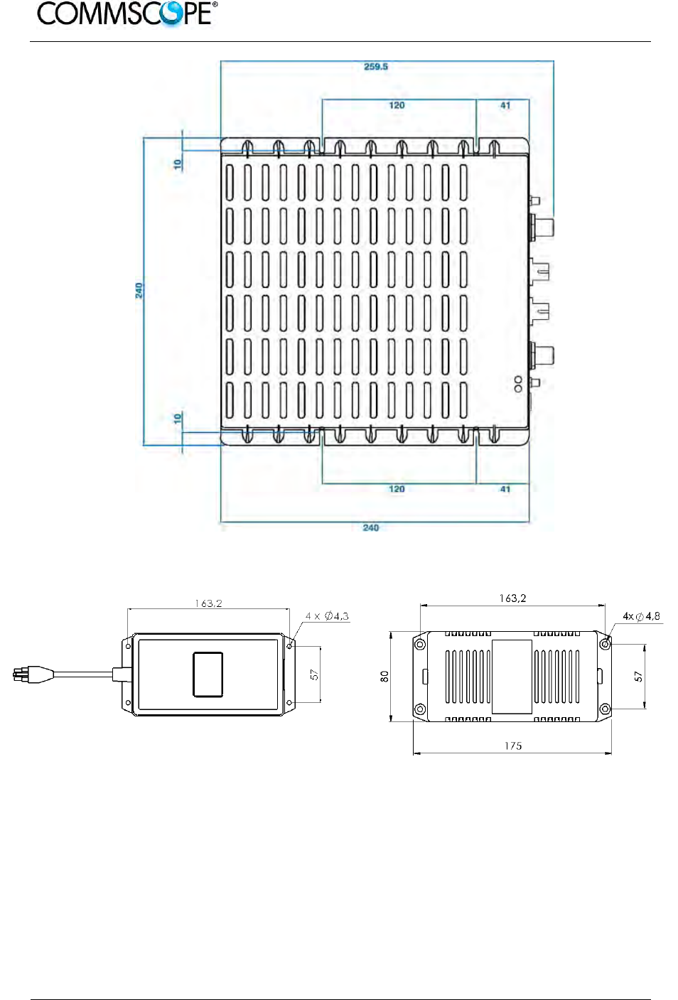
User’s Manual for ION-B Systems
Page 54 ION-B User Manual (MN024-15)_n_20150730.docx
Figure 4-27 Case B layout with dimensions
Figure 4-28 Layout of the +5Vdc power adapter with dimensions

User’s Manual for ION-B Systems
ION-B User Manual (MN024-
15)_n_20150730.docx Page 55
Figure 4-29 Layout of the +28Vdc power adapter with
dimensions
Once you have chosen a location for the RU, please follow these instructions:
1. In order to install the M4 dowels (not included) which hold up the TFAx RU, drill
five holes into the wall according the layout shown Figure 4-27 Case B layout
with dimensions.
2. Mount the TFAx to the wall by firmly fastening the screws into the dowels.
3. In order to install the M4 screw dowels (not included) which hold up the power
supply external adapter, drill four holes into the wall according the layout shown
in Figure 4-28 Layout of the +5Vdc power adapter with dimensions or Figure
4-29 Layout of the +28Vdc power adapter with dimensions.
4. Mount the external power supply adapter to the wall by firmly fastening the
screws.
5. Mount the splice holder inside the splice tray (not included).
6. Splice the optical fibres and close the splice tray. While handling the fibres, be
careful not to bend them.
7. Mount the splice tray beside the RU.
8. Connect the external adapter to the TFAx RU with the proper cable.
9. If the RU is -48 Vdc powered, use the -48 Vdc plug (included) in order to
connect the external adapter to the -48 Vdc supply. If the RU is 90/264 Vac-
powered, mount the 90/264 Vac plug (included) onto a power cord (not
included), and use this cable to connect the external adapter to mains.
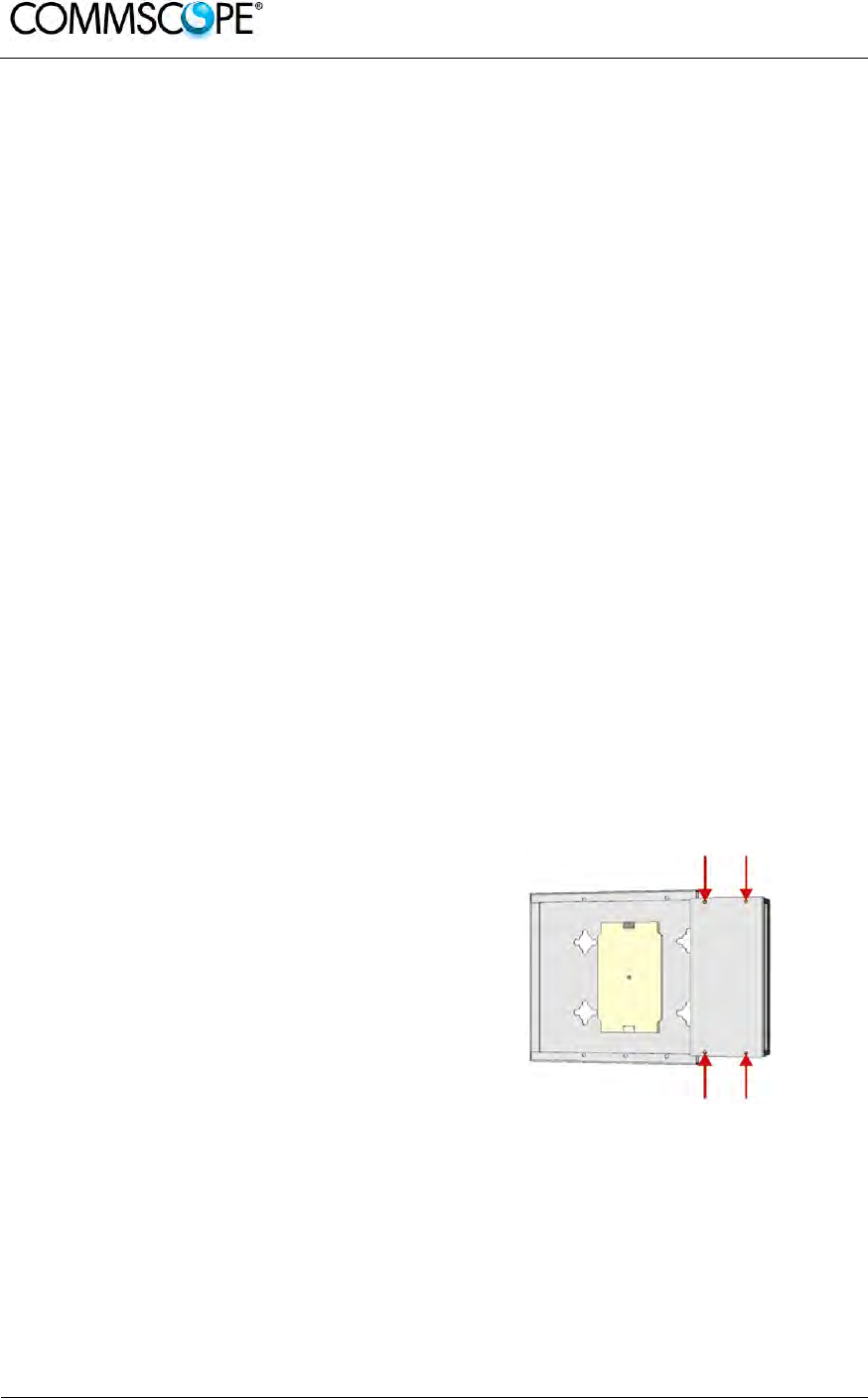
User’s Manual for ION-B Systems
Page 56 ION-B User Manual (MN024-15)_n_20150730.docx
10. Connect the antenna RF cables to the RF antenna ports. Connect the UL and
DL optical connectors. If the power cable has properly been connected to the
mains, both the green and the red LEDs should turn on. The green LED will
remain lit to indicate that the unit is powered on, while the red LED will turn off
as soon as the local unit is switched on.
11. Once the installation is finished, please follow the Remote Unit Start-up section
in order to carry out a proper system start up.
4.5.4. Installation of the Case B Remote Unit WITH the TKA04 Installation Kit
The TFAx Case B kit includes:
1. a RU TFAx
2. a TPSN external power supply adapter
3. a power supply plug
The TKA04 kit includes:
A. four screw dowels (mounting the wall bearing to the wall)
B. five screw dowels (mounting the TFAx Case B to the wall bearing)
C. a wall mounting box (wall bearing + cover)
D. a splice holder
Once you have chosen the position of the RU mounting case, please follow these
instructions:
1. Unscrew the four screws which lock
the lower cover of the TKA04 wall
bearing.
Figure 4-30 Dismount TKA cover
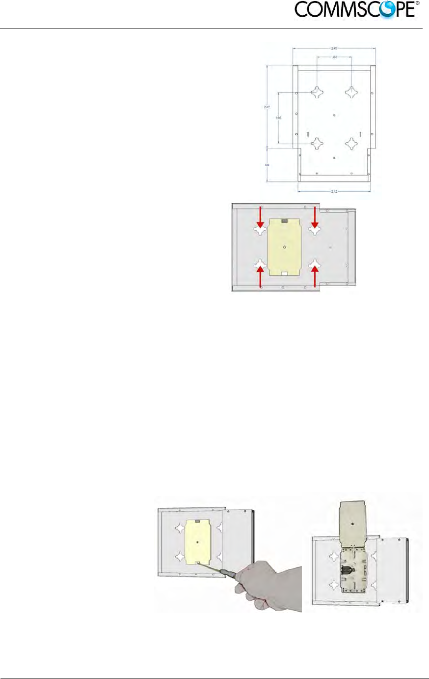
User’s Manual for ION-B Systems
ION-B User Manual (MN024-
15)_n_20150730.docx Page 57
Figure 4-31 Layout of the TKA installation
kit for TFAx Remote Unit, Case B
2. In order to install the M4
dowels (included) for the
TKA04 wall bearing, drill
four holes into the wall.
Figure 4-32 Installation: drill four holes
3. Mount the TKA04 wall bearing by firmly fastening the screws.
4. In order to install the M4 dowels (not included) which hold up the power supply
external adapter, drill four (two) holes into the wall according to the power supply
layout shown in Figure 4-28 Layout of the +5Vdc power adapter with dimensions
or Figure 4-29 Layout of the +28Vdc power adapter with dimensions
5. Mount the external power supply adapter to the wall by firmly fastening the
screws.
6. Carefully open the
splice tray by using a
screwdriver. Fasten the
splice holder inside the
splice tray. Splice the
optical fibres and close
the splice tray. While
handling the fibres, take
care not to bend them.
Close the splice tray.
Figure 4-33 Splice tray
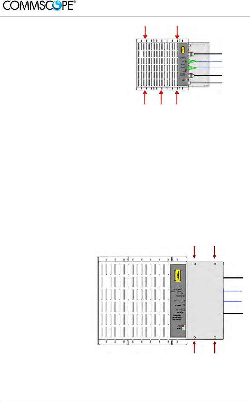
User’s Manual for ION-B Systems
Page 58 ION-B User Manual (MN024-15)_n_20150730.docx
7. Mount the RU to the wall-
bearing by using the
included screws.
Figure 4-34 Mount the Remote Unit
8. If the RU is -48 Vdc powered, use the -48 Vdc plug (included) in order to
connect the external adapter to the -48 Vdc mains. If the RU is 90/264 Vac-
powered, mount the 90/264 Vac plug (included) onto a power cord (not
included), and use this cable in order to connect the external adapter to the
mains.
9. Connect the antenna RF cables to the RF antenna ports. Connect the UL and
DL optical connectors. If the power cable has properly been connected to the
mains, both the green and the red LEDs should turn on. The green LED will
remain lit to indicate that the unit is powered on, while the red LED will turn off
as soon as the local unit is switched on (for further details about the start up of
the system, please refer to the Remote Unit Start-up section).
10. Mount the lower cover
by fastening the 4
screws.
Figure 4-35 Mount TKA cover
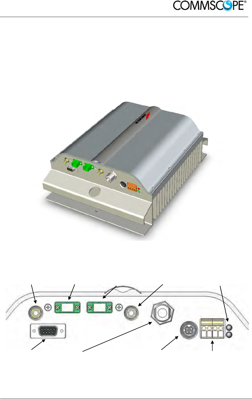
User’s Manual for ION-B Systems
ION-B User Manual (MN024-
15)_n_20150730.docx Page 59
4.6. CASE R2 REMOTE UNIT
4.6.1. Specifications
Dimensions: mm 330 x 250 x 122.5
(inches 13 x 9.8 x 4.8)
Weight: Please refer to the Remote Unit dedicated bulletin in order to know
the updated data about the weight of a specific Case R2 RU.
Figure 4-36 Case R2 Remote Unit
RF auxiliary UL
channel input UL optical
port DL optical
port RF auxiliary DL
channel input LED alerts
Green = power ON
Red = major alarm
RS-232 port
RF antenna port
Power supply
connector
External alarm
connection
Figure 4-37 Case R2 front view
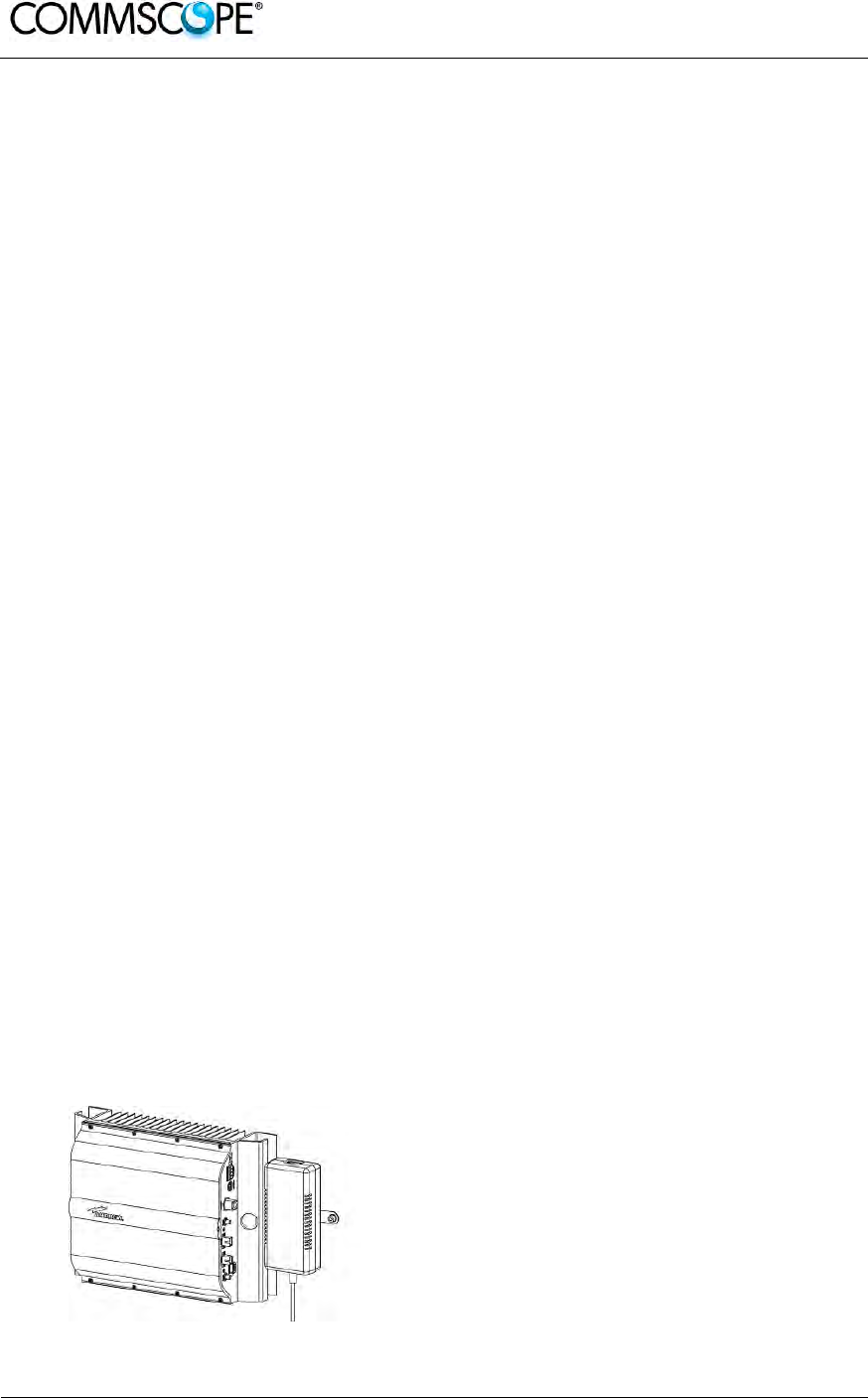
User’s Manual for ION-B Systems
Page 60 ION-B User Manual (MN024-15)_n_20150730.docx
RF ports
• 1 RF antenna port, transmitting/receiving signals to/from distributed antennas.
This RF antenna port is a duplexed N-female connector. The port can be
connected to the antenna either directly (i.e. through RF jumper cables) or
through splitters, thus allowing more antennas to be fed.
• 1 RF auxiliary input and 1 RF auxiliary output (designed to receive and transmit
additional signals). Auxiliary input and output ports are SMA-female connectors.
Optical ports
• 1 optical output port, transmitting UL signals to TFLN master optical TRX;
• 1 optical input port, receiving DL signals from TFLN master optical TRX.
External alarms inputs
A Case R2E TFAx is provided with two alarm contact inputs which can be cabled to
collect the alarms from any external device (i.e. an external booster). The alarm
information regarding this external device are then signalled through the TFAH front
panel red LED and displayed on the Supervision System.
4.6.2. TFAx Case R2 Installation
Each Case R2 Remote Unit kit includes:
1. a RU TFAx
2. a TPSN external power supply adapter
3. a power supply plug
The Case R2 Remote Unit has to be mounted with heat-dissipation fins in vertical
position. The suggested installation layout is shown in Figure 4-38 Case R2 RU,
mounted with power supply, with the external power supply mounted side by side to
the Remote Unit, using a common screw anchor to support both the Remote Unit’s
right side and the power supply’s left wing.
An external splice box (not included) may be mounted side by side to the power
supply or to the Remote Unit, sharing an anchor with one of them.
Figure 4-38 Case R2 RU, mounted with
power supply
Once you have chosen the position of the RU mounting case, please follow these
instructions:
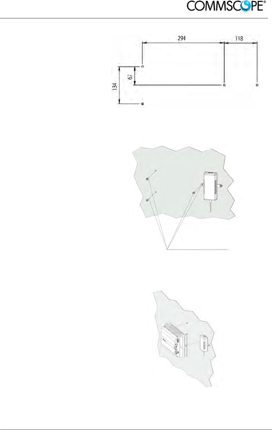
User’s Manual for ION-B Systems
ION-B User Manual (MN024-
15)_n_20150730.docx Page 61
1. Drill four holes to the
wall and install the four
M6 dowels (not
included).
Alternatively, you can
choose to install your
power supply close to
the RU.
Figure 4-39 Installation: drill four holes
2. Insert the four M6
dowels in the holes,
and fasten the power
supply to the wall. If
you planned to use a
common screw anchor
to support both the RU
and the external power
supply, take care not to
fasten the screw to this
hole until you fastened
the RU.
Figure 4-40 Mount the PSU
3. Fasten the Remote Unit
to the wall.
Figure 4-41 Mount the RU
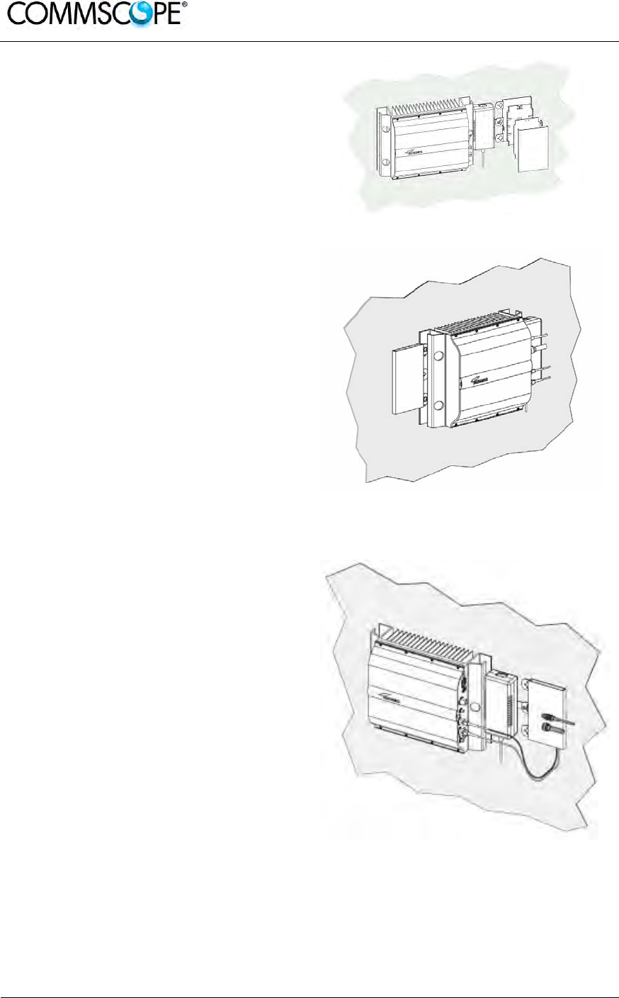
User’s Manual for ION-B Systems
Page 62 ION-B User Manual (MN024-15)_n_20150730.docx
4. Fasten the splice holder (not
included) inside a splice tray (not
included). Make the optical
splices and close the splice tray.
Place the splice tray inside a
splice box (not included), and
mount the splice box beside the
Remote Unit. The suggested
installation position is side by side
to the power supply or to the
Remote Unit, using one of their
M6 dowels already installed to
support the splice box as well.
Note: Take care not to bend the fibres
too much.
Figure 4-42 Mount the splice tray
Figure 4-43 Mount the splice box
5. Now connect the RF cables, the
optical connectors, and the power
supply connector to the Remote
Unit. Take care to connect UL and
DL fibres properly.
After the Remote Unit has been
properly cabled, insert the power
plug in the external power supply
adapter, so as to connect it to the
mains.
Figure 4-44 Mount the connectors
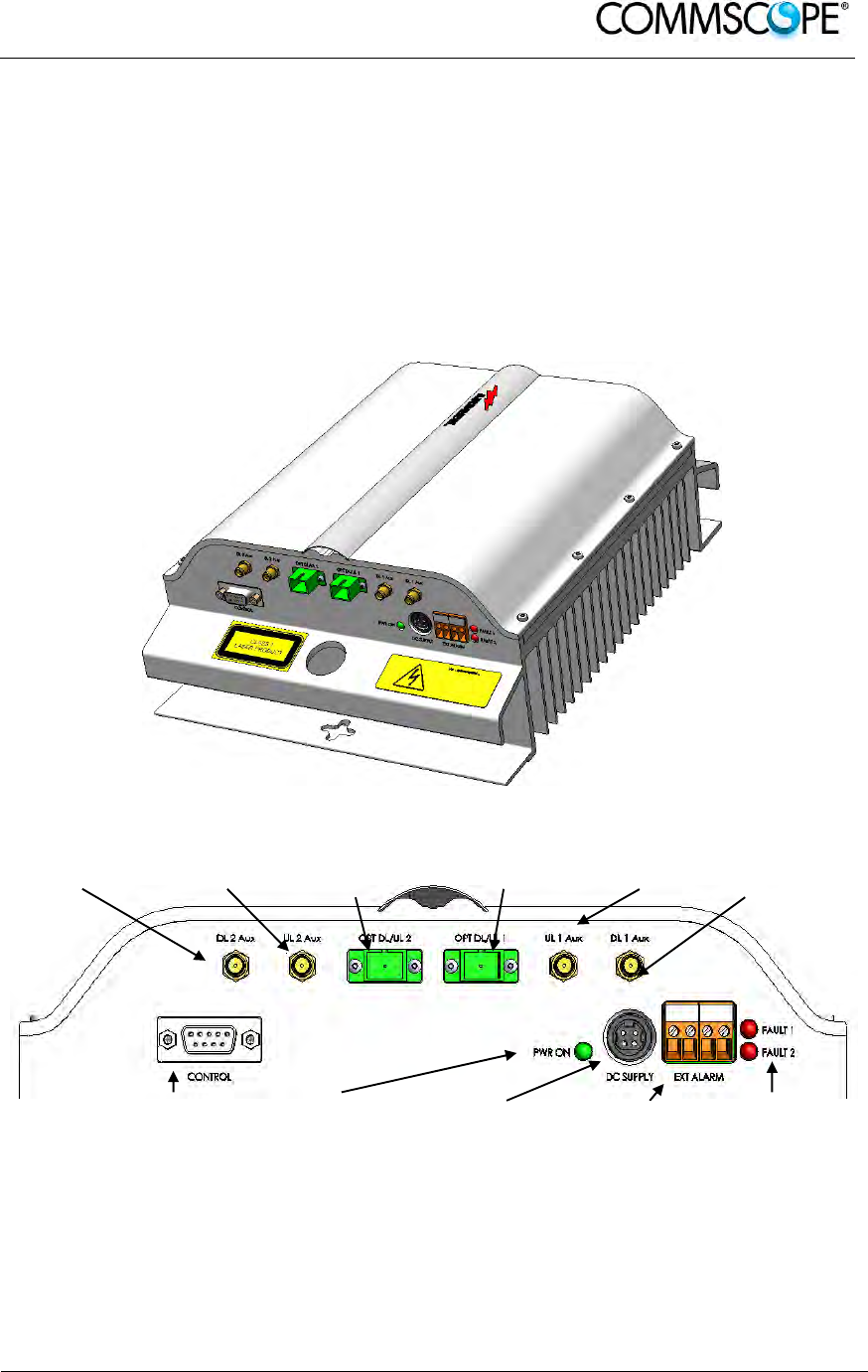
User’s Manual for ION-B Systems
ION-B User Manual (MN024-
15)_n_20150730.docx Page 63
4.7. CASE R2 MIMO REMOTE UNIT
4.7.1. Specifications
Dimensions: mm 330 x 250 x 122.5
(inches 13 x 9.8 x 4.8)
Weight: Please refer to the Remote Unit dedicated bulletin in order to know
the updated data about the weight of a specific Case R2 RU.
Figure 4-45 Case R2 MIMO Remote Unit
RF auxiliary
DL 2 RF auxiliary
UL 2 Optical
DL/UL port 2 Optical
DL/UL port 1 RF auxiliary
UL 1 RF auxiliary
DL 1
RS-232 port Power
LED Power supply
connector External
alarm
connector
Fault LEDs
Figure 4-46 Case R2 MIMO front view

User’s Manual for ION-B Systems
Page 64 ION-B User Manual (MN024-15)_n_20150730.docx
RF antenna port 1 RF antenna port 2
Figure 4-47 Case R2 MIMO rear view
RF ports
• 2 RF antenna ports, transmitting/receiving signals to/from distributed antennas.
These RF antenna ports are duplexed N-female connectors. The ports can be
connected to the antenna either directly (i.e. through RF jumper cables) or
through splitters, thus allowing more antennas to be fed.
• 2 RF auxiliary inputs and 2 RF auxiliary outputs (designed to receive and
transmit additional signals). Auxiliary input and output ports are SMA-female
connectors.
Optical ports
• 2 optical input/output ports, transmitting UL and DL signals to the Master Units
optical transceiver TFLN2604W/4.
Note: The optical link from the Case R2 MIMO Remote Unit to the Master Unit can
only be done with TFLN2604W/4.
External alarms inputs
A Case R2 TFAx is provided with two alarm contact inputs which can be cabled to
collect the alarms from any external device (i.e. an external booster). The alarm
information regarding this external device are then signalled through the TFAH front
panel red LEDs and displayed on the Supervision System.
LEDs
• The Power LED signals the status of the Case R2 MIMO TFAx; Off – No power
applied, Green – power is applied, Red – Major failure
• The Fault LEDs indicate the status of the devices monitored via the external
alarms connectors. Red – Failure.
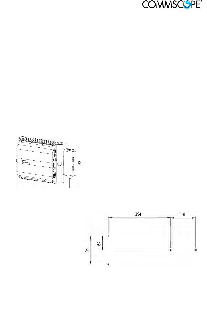
User’s Manual for ION-B Systems
ION-B User Manual (MN024-
15)_n_20150730.docx Page 65
4.7.2. TFAx Case R2 MIMO Installation
Each Case R2 MIMO Remote Unit kit includes:
1. a RU TFAx
2. a TPSN external power supply adapter
3. a power supply plug
The Case R2 MIMO Remote Unit has to be mounted with heat-dissipation fins in
vertical position. The suggested installation layout is shown in Figure 4-38 Case R2
RU, mounted with power supply, with the external power supply mounted side by
side to the Remote Unit, using a common screw anchor to support both the Remote
Unit’s right side and the power supply’s left wing.
An external splice box (not included) may be mounted side by side to the power
supply or to the Remote Unit, sharing an anchor with one of them.
Figure 4-48 Case R2 RU, mounted with
power supply
Once you have chosen the position of the RU mounting case, please follow these
instructions:
1. Drill four holes to the
wall and install the four
M6 dowels (not
included).
Alternatively, you can
choose to install your
power supply close to
the RU.
Figure 4-49 Installation: drill four holes
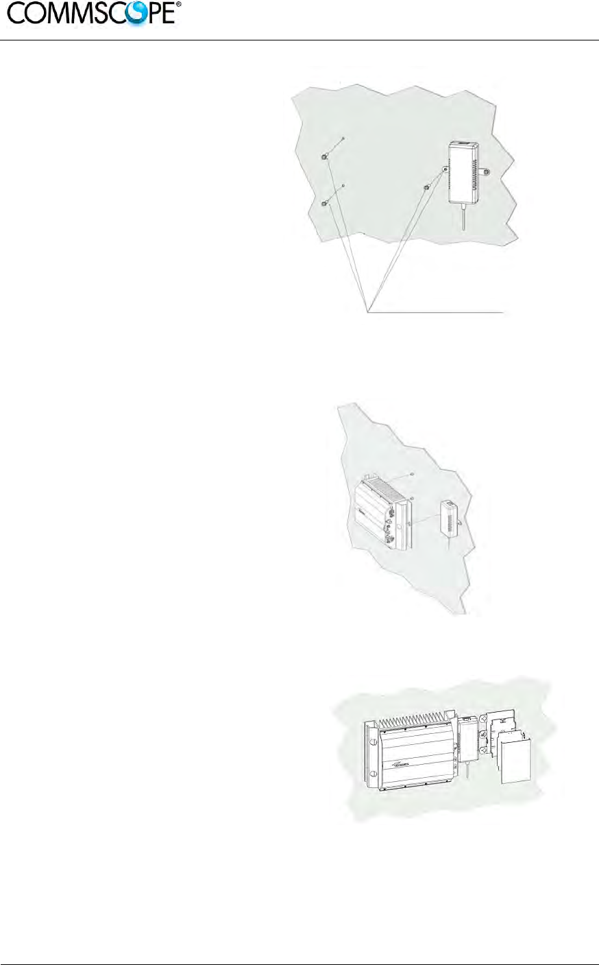
User’s Manual for ION-B Systems
Page 66 ION-B User Manual (MN024-15)_n_20150730.docx
2. Insert the four M6
dowels in the holes,
and fasten the power
supply to the wall. If
you planned to use a
common screw anchor
to support both the RU
and the external power
supply, take care not to
fasten the screw to this
hole until you fastened
the RU.
Figure 4-50 Mount the PSU
3. Fasten the Remote Unit
to the wall.
Figure 4-51 Mount the RU
4. Fasten the splice holder (not
included) inside a splice tray (not
included). Make the optical
splices and close the splice tray.
Place the splice tray inside a
splice box (not included), and
mount the splice box beside the
Remote Unit. The suggested
installation position is side by side
to the power supply or to the Figure 4-52 Mount the splice tray
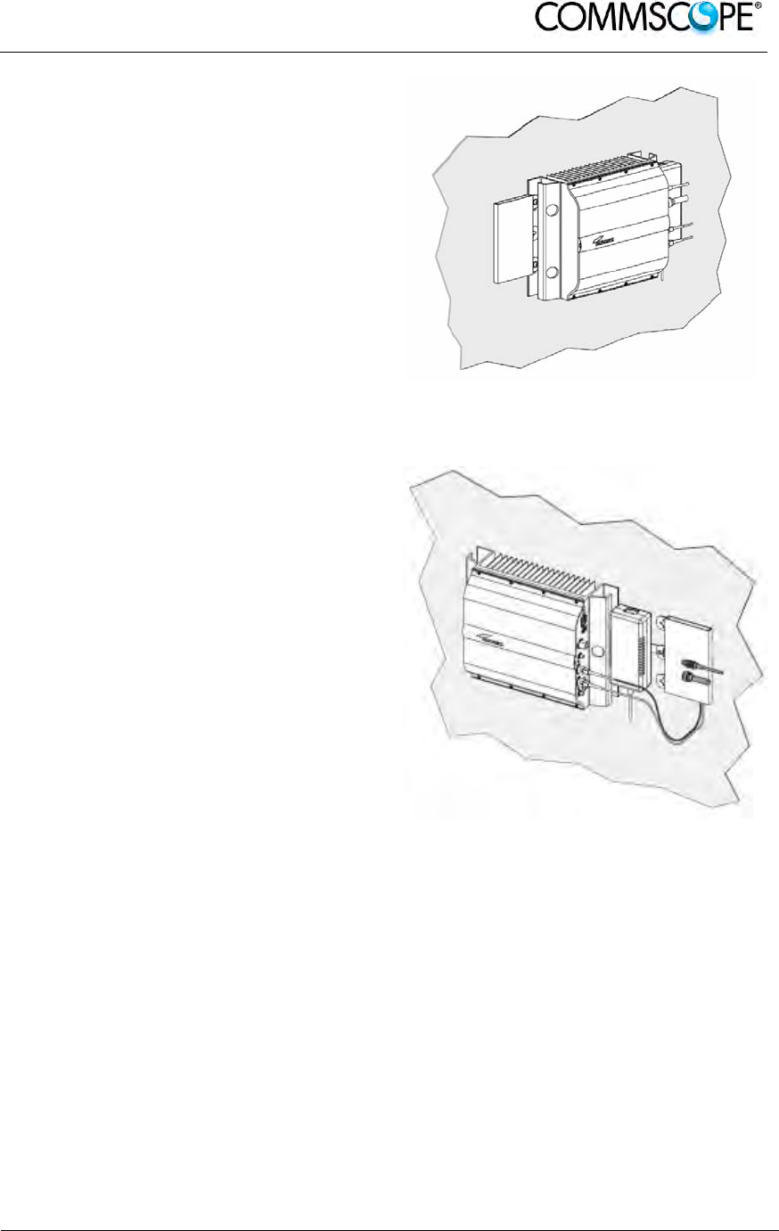
User’s Manual for ION-B Systems
ION-B User Manual (MN024-
15)_n_20150730.docx Page 67
Remote Unit, using one of their
M6 dowels already installed to
support the splice box as well.
Note: Take care not to bend the fibres
too much.
Figure 4-53 Mount the splice box
5. Now connect the RF cables, the
optical connectors, and the power
supply connector to the Remote
Unit. Take care to connect UL and
DL fibres properly.
After the Remote Unit has been
properly cabled, insert the power
plug in the external power supply
adapter, so as to connect it to the
mains.
Figure 4-54 Mount the connectors
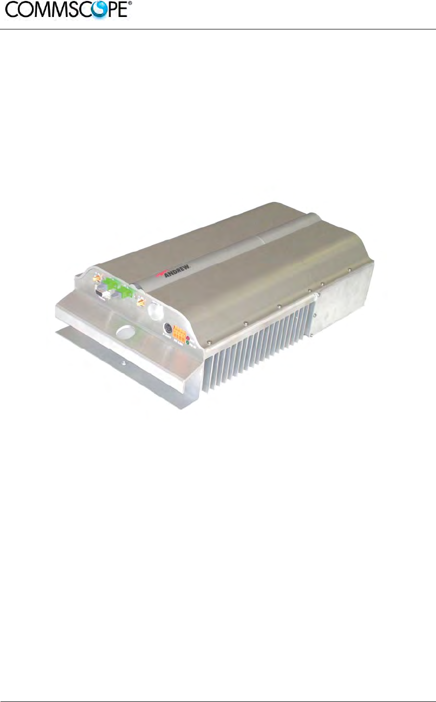
User’s Manual for ION-B Systems
Page 68 ION-B User Manual (MN024-15)_n_20150730.docx
4.8. CASE R2E REMOTE UNIT
4.8.1. Specifications
Dimensions: mm 513 x 250 x 125
(inches 19.3 x 9.9 x 4.9)
Weight: Please refer to the Remote Unit dedicated bulletin in order to know
the updated data about the weight of your Case R2E Remote Unit.
Figure 4-55 Case R2E Remote Unit
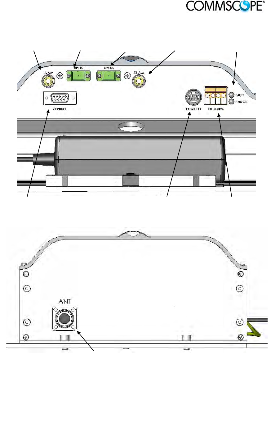
User’s Manual for ION-B Systems
ION-B User Manual (MN024-
15)_n_20150730.docx Page 69
RF auxiliary UL
channel input UL optical
port DL optical
port RF auxiliary DL
channel input LED alerts
Green = power ON
Red = major alarm
RS-232 port
Power supply
connector
External alarm
connection
Figure 4-56 Case R2E front view
RF antenna port
Figure 4-57 Case R2E rear view

User’s Manual for ION-B Systems
Page 70 ION-B User Manual (MN024-15)_n_20150730.docx
RF ports
• 1 RF antenna port, transmitting/receiving signals to/from distributed antennas.
This RF antenna port is a duplexed N-female connector. The port can be
connected to the antenna either directly (i.e. through RF jumper cables) or
through splitters, thus allowing more antennas to be fed.
• 1 RF auxiliary input and 1 RF auxiliary output (designed to receive and transmit
additional signals). Auxiliary input and output ports are SMA-female connectors.
Optical ports
• 1 optical output port, transmitting UL signals to TFLN master optical TRX;
• 1 optical input port, receiving DL signals from TFLN master optical TRX.
External alarms inputs
A Case R2E TFAx is provided with two alarm contact inputs which can be cabled to
collect the alarms from any external device (i.e. an external booster). The alarm
information regarding this external device are then signalled through the TFAH front
panel red LED and displayed on the Supervision System.
4.8.2. TFAx Case R2E Installation
Each Case R2E Remote Unit kit includes:
1. a RU TFAx
2. a TPSN external power supply adapter
3. a power supply plug
The Case R2E Remote Unit has to be mounted with heat-dissipation fins in vertical
position. The suggested installation layout is shown in Figure 4-58 Case R2E
Remote Unit, mounted with power supply, with the external power supply mounted
side by side to the Remote Unit, using a common screw anchor to support both the
Remote Unit’s right side and the power supply’s left wing.
An external splice box (not included) may be mounted side by side to the power
supply or to the Remote Unit, sharing an anchor with one of them.
Figure 4-58 Case R2E Remote Unit, mounted with
power supply
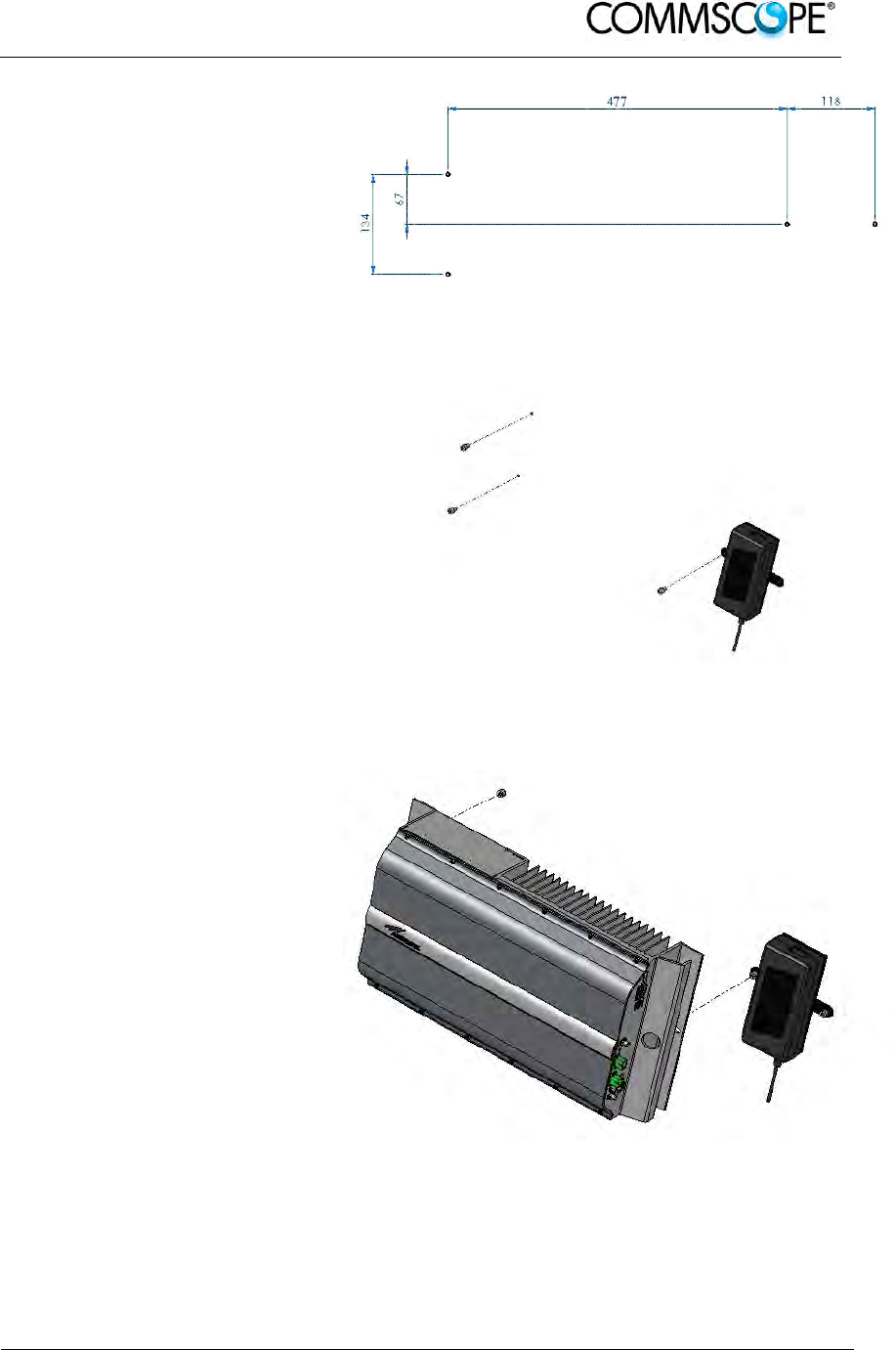
User’s Manual for ION-B Systems
ION-B User Manual (MN024-
15)_n_20150730.docx Page 71
1. Drill four holes to the wall
and install the four M6
dowels (not included).
Alternatively, you can
choose to install your
power supply close to
the RU.
Figure 4-59 Drilling layout
2. Insert the four M6
dowels into the holes
and fasten the power
supply to the wall.
If you planned to use a
common screw anchor to
support both the Remote
Unit and the external
power supply, take care
not to screw this dowels
till you fastened the
Remote Unit.
Figure 4-60 Fastening the power supply
3. Fasten the Remote Unit
to the wall and tighten
the 4 dowels.
Figure 4-61 Fastening the RU

User’s Manual for ION-B Systems
Page 72 ION-B User Manual (MN024-15)_n_20150730.docx
4. Fasten the splice holder (not
included) inside a splice tray (not
included), make the optical
splices and close the splice tray.
Mount the splice box beside the
Remote Unit. Suggested
installation position is side by
side to the power supply using
one of their M6 dowels already
deployed for the power supply.
Note: Take care not to bend the
fibres too much.
Figure 4-62 Fastening the splice box
5. Now connect the RF cables, the optical connectors, and the power supply
connectors to the Remote Unit. Take care to connect UL and DL fibres
properly. Use the fibre protection (provided with the splice box) to protect the
fibres.
When the Remote Unit has been properly cabled, insert the power plug in
the external power supply adapter, so as to connect it to mains.
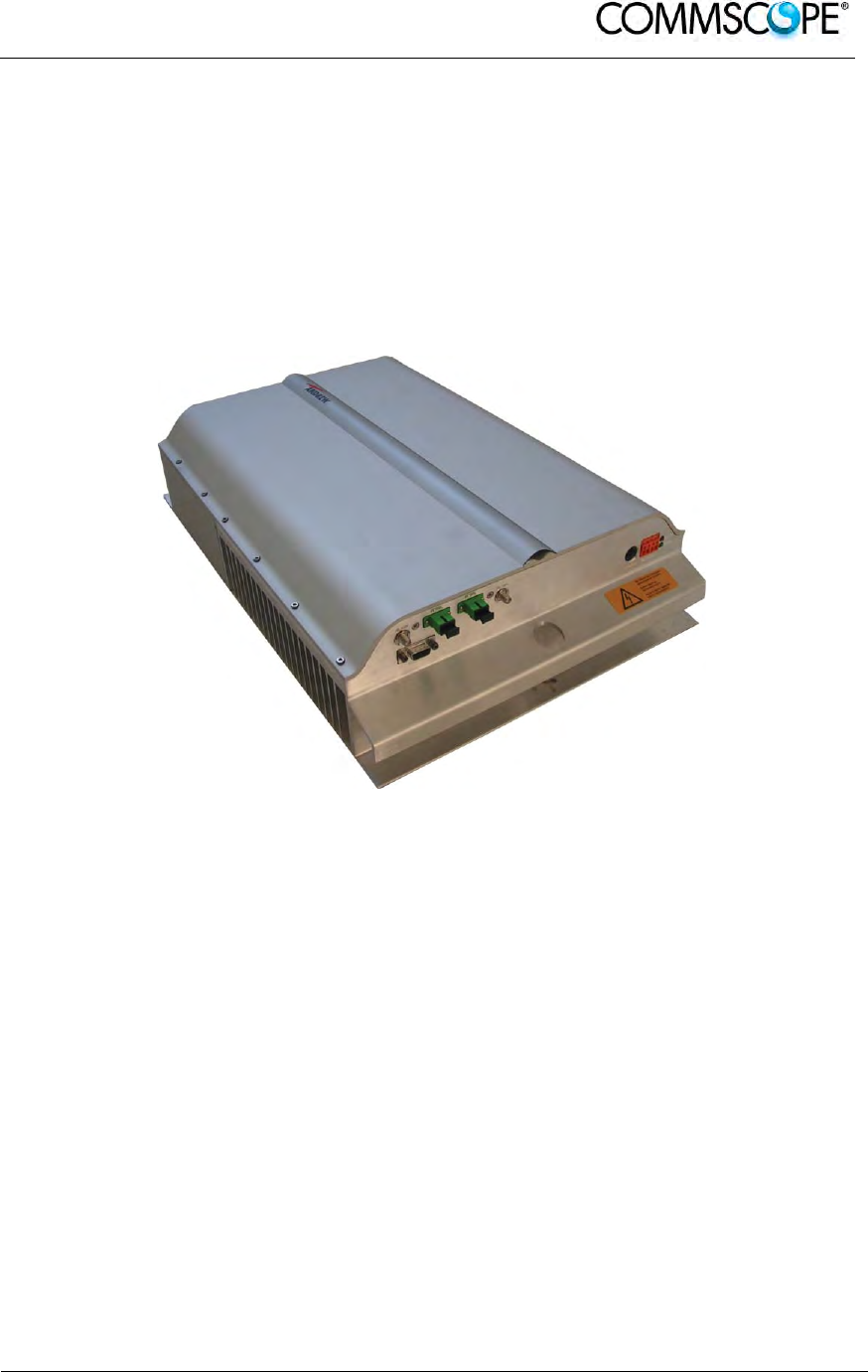
User’s Manual for ION-B Systems
ION-B User Manual (MN024-
15)_n_20150730.docx Page 73
4.9. CASE R4E REMOTE UNIT
4.9.1. Specifications
Dimensions: mm 515 x 335 x 125
(inches 20.3 x 13.2 x 4.9)
Weight: Please refer to the Remote Unit dedicated bulletin in order to know
the updated data about the weight of your Case R4E Remote Unit.
Figure 4-63 Case R4E Remote Unit
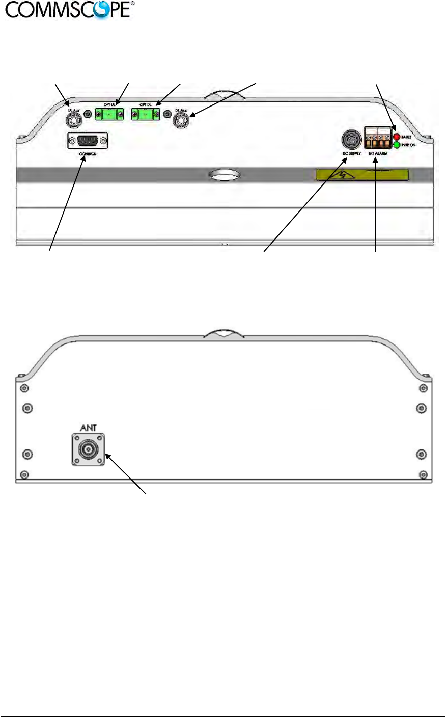
User’s Manual for ION-B Systems
Page 74 ION-B User Manual (MN024-15)_n_20150730.docx
RF auxiliary UL
channel input UL optical
port DL optical
port RF auxiliary DL
channel input LED alerts
Green = power ON
Red = major alarm
RS-232 port
Power supply
connector
External alarm
connection
Figure 4-64 Case R4E front view
RF antenna port
Figure 4-65 Case R4E rear view

User’s Manual for ION-B Systems
ION-B User Manual (MN024-
15)_n_20150730.docx Page 75
RF ports
• 1 RF antenna port, transmitting/receiving signals to/from distributed antennas.
This RF antenna port is a duplexed N-female connector. The port can be
connected to the antenna either directly (i.e. through RF jumper cables) or
through splitters, thus allowing more antennas to be fed.
• 1 RF auxiliary input and 1 RF auxiliary output (designed to receive and transmit
additional signals). Auxiliary input and output ports are SMA-female connectors.
Optical ports
• 1 optical output port, transmitting UL signals to TFLN master optical TRX;
• 1 optical input port, receiving DL signals from TFLN master optical TRX.
External alarms inputs
A Case R4E TFAx is provided with two alarm contact inputs which can be cabled to
collect the alarms from any external device (i.e. an external booster). The alarm
information regarding this external device are then signalled through the TFAH front
panel red LED and displayed on the Supervision System.
4.9.2. TFAx Case R4E Installation
Each Case R4E Remote Unit kit includes:
1. a RU TFAx
2. a TPSN external power supply adapter
3. a power supply plug
The Case R4E Remote Unit has to be mounted with heat-dissipation fins in vertical
position. The suggested installation layout is shown in Figure 4-66 Case R4E
Remote Unit, mounted with power supply, with the external power supply mounted
close to the Remote Unit. An external splice box (not included) may be mounted side
by side to the power supply or to the Remote Unit, sharing an anchor with one of
them.
DC version
AC version
Figure 4-66 Case R4E Remote Unit, mounted with power supply
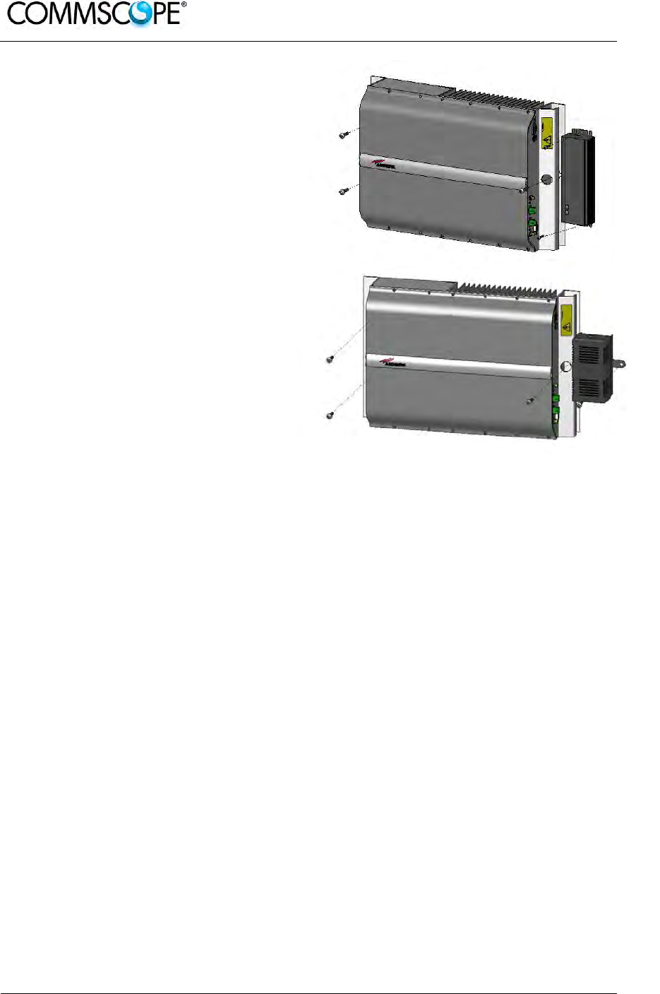
User’s Manual for ION-B Systems
Page 76 ION-B User Manual (MN024-15)_n_20150730.docx
1. Drill four holes to the wall and
install the four M6 dowels
(not included) to fix the
Remote Unit.
For DC versions PSU can be
installed re-using one of the
RU fixing holes (and M6
dowels, not provided). For
AC version the PSU can be
installed close to the RU,
drilling two holes to the wall
and installing two M4 dowels
(not provided) to fix it.
2. Insert the four M6/M4 dowels
into the holes and fasten the
power supply to the wall.
Fasten the Remote Unit to
the wall and tighten the 4
dowels.
Figure 4-67 Fastening the power supply and RU
3. Fasten the splice holder (not included) inside a splice tray (not included), make the
optical splices and close the splice tray. Mount the splice box beside the Remote
Unit.
Note: Take care not to bend the fibres too much.
4. Now connect the RF cables, the optical connectors, and the power supply
connectors to the Remote Unit. Take care to connect UL and DL fibres properly.
Use the fibre protection (provided with the splice box) to protect the fibres.
When the Remote Unit has been properly cabled, insert the power plug in the
external power supply adapter, so as to connect it to mains.
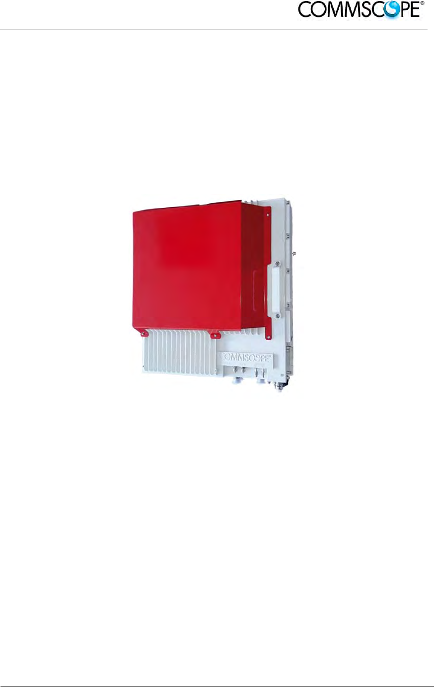
User’s Manual for ION-B Systems
ION-B User Manual (MN024-
15)_n_20150730.docx Page 77
4.10. CASE U REMOTE UNIT
4.10.1. Specifications
Dimensions: mm 514 x 480 x 205
(inches 20.3 x 18.9 x 8.1)
Weight: Please refer to the Remote Unit dedicated e-catalog entry in order to
know the updated data about the weight of your Case U Remote
Unit.
Figure 4-68 Case U Remote Unit
Case U Remote Units are available with and without the red cover, which serves for
indication of public safety services equipment.
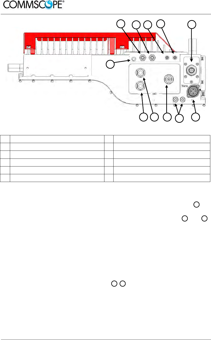
User’s Manual for ION-B Systems
Page 78 ION-B User Manual (MN024-15)_n_20150730.docx
Figure 4-69 Case U connectors
A Status LED G Power supply connector
B Alarms lower band H Grounding bolts
C Alarms higher band(s) I UL/DL antenna port higher band(s)
D Expansion UL port J UL lower band, not connected in 2 band
E Expansion DL port K DL lower band, not connected in 2 band
F UL / DL optical ports
Antenna Port
In the two band configuration the RU has one duplexed N-female antenna port for
transmitting and receiving signals to and from distributed antennas. In the three band
configuration the RU also has two non-duplexed N-female antenna ports and
for UL and DL. These RF ports can be connected directly to an antenna (i.e. using
RF jumper cables) or through splitters, allowing additional antennas to be fed by the
RU.
Status LED
The status LED provides a visual warning of an alarm condition. The color of the LED
indicates the severity of the alarm.
Expansion Ports
The Expansion UL and Expansion DL ports are QMA female connectors that
are used to connect to a CommScope expansion unit to provide additional bands.
FD
KJ
I
A
BC D E
H GI J
F
K

User’s Manual for ION-B Systems
ION-B User Manual (MN024-
15)_n_20150730.docx Page 79
Optical Ports
The LC-APC optical connectors are used to send and receive the signals between
the RU and the Master Unit’s OTRx modules.
A DL optical port receives downlink signals from the MU OTRx.
A UL optical port transmits uplink signals to the MU OTRx.
Mains Connector
The RU receives its power through the Mains connector . The type of connector is
dependent on the RU model. A 4-pin Amphenol connector is used for AC models and
standard DC models. A 7-pin Amphenol connector is used for DC models powered
by a dual cable supply.
Alarm connectors
The RU has two alarm relay outputs that can be used report alarms to external
devices. The Alarm connectors , lower band and , higher bands are 5-pin Binder
connectors.
CB
G
F
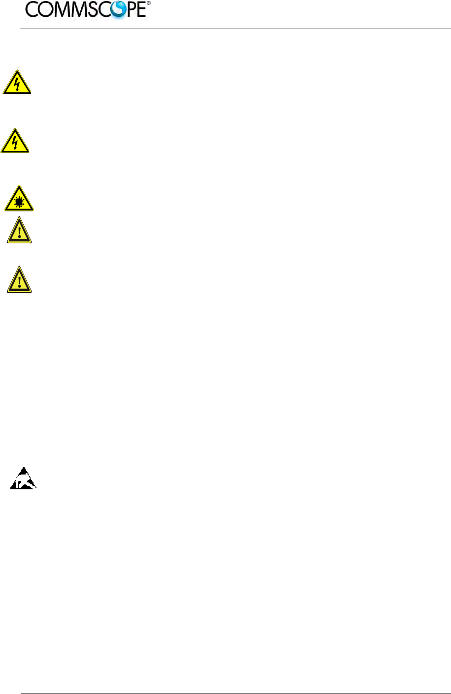
User’s Manual for ION-B Systems
Page 80 ION-B User Manual (MN024-15)_n_20150730.docx
4.10.2. Health and Safety
1. Danger: Electrical hazard. Danger of death or fatal injury from electrical
current. Obey all general and regional installation and safety regulations
relating to work on high voltage installations, as well as regulations
covering correct use of tools and personal protective equipment.
2. Danger: Electrical hazard. Danger of death or fatal injury from electrical
current inside the unit in operation. Before opening the unit, disconnect
mains power.
3. Caution: Laser radiation. Risk of eye injury in operation. Do not stare into the
beam; do not view it directly or with optical instruments.
4. Caution: High frequency radiation in operation. Risk of health hazards associated
with radiation from the unit’s inner conductor of the antenna port(s). Disconnect
mains before connecting or replacing antenna cables.
5. Caution: High frequency radiation in operation. Risk of health hazards associated
with radiation from the antenna(s) connected to the unit. Implement prevention
measures to avoid the possibility of close proximity to the antenna(s) while in
operation.
4.10.3. Property Damage Warnings
1. Attention: Due to power dissipation, the Remote Unit may reach a very high
temperature. Do not operate this equipment on or close to flammable materials.
Use caution when servicing the unit.
2. Notice: Although the Remote Unit is internally protected against overvoltage, it is
strongly recommended to ground (earth) the antenna cables close to the
repeater’s antenna connectors for protection against atmospheric discharge.
3. Notice: ESD precautions must be observed. Before commencing maintenance
work, use the available grounding (earthing) system to connect ESD protection
measures.
4. Notice: Only suitably qualified personnel are allowed to work on this unit and only
after becoming familiar with all safety notices, installation, operation and
maintenance procedures contained in this manual.
5. Notice: Keep operating instructions within easy reach and make them available
to all users.
6. Attention: Only authorized and trained personnel are allowed to open the unit
and get access to the inside.

User’s Manual for ION-B Systems
ION-B User Manual (MN024-
15)_n_20150730.docx Page 81
7. Notice: Read and obey all the warning labels attached to the unit. Make sure that
all warning labels are kept in a legible condition. Replace any missing or
damaged labels.
8. Notice: Only license holders for the respective frequency range are allowed to
operate this unit.
9. Notice: Make sure the repeater settings are correct for the intended use (refer to
the manufacturer product information) and regulatory requirements are met. Do
not carry out any modifications or fit any spare parts, which are not sold or
recommended by the manufacturer.
4.10.4. Compliance
1. Notice: For installations which have to comply with European EN50385 exposure
compliance requirements, the following Power Density limits/guidelines (mW/cm²)
according to ICNIRP are valid:
o 0.2 for frequencies from 10 MHz to 400 MHz
o F (MHz) / 2000 for frequencies from 400 MHz to 2 GHz
o 1 for frequencies from 2 GHz to 300 GHz
2. Notice: For installations, which have to comply with FCC RF exposure
requirements, the antenna selection and installation must be completed in a way
to ensure compliance with those FCC requirements. Depending on the RF
frequency, rated output power, antenna gain, and the loss between the repeater
and antenna, the minimum distance D to be maintained between the antenna
location and human beings is calculated according to this formula:
]/[
][
][
2
4
cmmW
mW
cm
PD
P
D
where
P (mW) is the radiated power at the antenna, i.e. the max. rated repeater
output power in addition to the antenna gain minus the loss between the
repeater and the antenna.
PD (mW/cm²) is the allowed Power Density limit acc. to 47 CFR 1.1310 (B)
for general population / uncontrolled exposures which is
o F (MHz) / 1500 for frequencies from 300MHz to 1500MHz
o 1 for frequencies from 1500MHz to 100,000MHz
RF exposure compliance may need to be addressed at the time of licensing, as
required by the responsible FCC Bureau(s), including antenna co-location
requirements of 1.1307(b)(3).

User’s Manual for ION-B Systems
Page 82 ION-B User Manual (MN024-15)_n_20150730.docx
3. Notice: Installation of this equipment is in full responsibility of the installer, who
has also the responsibility, that cables and couplers are calculated into the
maximum gain of the antennas, so that this value, which is filed in the FCC Grant
and can be requested from the FCC data base, is not exceeded. The industrial
boosters are shipped only as a naked booster without any installation devices or
antennas as it needs for professional installation.
4. Notice: For installations which have to comply with FCC/Industry Canada
requirements:
English:
This device complies with FCC Part 15 and Industry Canada license exempt RSS
standard(s). Operation is subject to the following two conditions: (1) this device
may not cause interference, and (2) this device must accept any interference,
including interference that may cause undesired operation of the device.
This device complies with Health Canada’s Safety Code. The installer of this
device should ensure that RF radiation is not emitted in excess of the Health
Canada’s requirement. Information can be obtained at http:
//www.hc-sc.gc.ca/ewh-semt/pubs/radiation/radio_guide-lignes_direct-eng.php.
Changes or modifications not expressly approved by the party responsible for
compliance could void the user’s authority to operate the equipment.
French:
Cet appareil est conforme à FCC Partie15 d’Industrie Canada RSS standard
exempts de licence (s). Son utilisation est soumise à Les deux conditions
suivantes: (1) cet appareil ne peut pas provoquer d’interférences et (2) cet
appareil doit accepter Toute interférence, y compris les interférences qui peuvent
causer un mauvais fonctionnement du dispositif.
Cet appareil est conforme avec Santé Canada Code de sécurité 6. Le
programme d’installation de cet appareil doit s’assurer que les rayonnements RF
n’est pas émis au-delà de I’exigence de Santé Canada. Les informations peuvent
être obtenues:
http://www.hc-sc.gc.ca/ewh-semt/pubs/radiation/radio_guide-lignes_direct-
fra.php
Les changements ou modifications non expressément approuvés par la partie
responsable de la conformité pourraient annuler l'autorité de l'utilisateur à utiliser
cet équipement.
5. Notice: Corresponding local particularities and regulations must be observed. For
national deviations, please refer to the respective documents included in the
manual CD that is delivered with the unit.

User’s Manual for ION-B Systems
ION-B User Manual (MN024-
15)_n_20150730.docx Page 83
6. Note: For a Class A digital device or peripheral:
This equipment has been tested and found to comply with the limits for a Class A
digital device, pursuant to part 15 of the FCC Rules. These limits are designed to
provide reasonable protection against harmful interference when the equipment is
operated in a commercial environment. This equipment generates, uses, and can
radiate radio frequency energy and, if not installed and used in accordance with
the instruction manual, may cause harmful interference to radio communications.
Operation of this equipment in a residential area is likely to cause harmful
interference in which case the user will be required to correct the interference at
his own expense.
7. Note: This unit complies with European standard EN60950.

User’s Manual for ION-B Systems
Page 84 ION-B User Manual (MN024-15)_n_20150730.docx
4.10.5. TFAx Case U Mechanical Installation
Each Case U Remote Unit kit includes:
1. a RU TFAx
2. a power supply plug
4.10.5.1. Health and Safety for Mechanical Installation
Read and observe chapter 4.10.2. Health and Safety.
1. Caution: Risk of injury by the considerable weight of the unit falling. Ensure there
is adequate manpower to handle the weight of the system.
2. Caution: Risk of serious personal injury by equipment falling due to improper
installation. The installer must verify that the supporting surface will safely
support the combined load of the electronic equipment and all attached hardware
and components. The screws and dowels (wall anchors) used should also be
appropriate for the structure of the supporting wall.
4.10.5.2. Property Damage Warnings for Mechanical Installation
1. Attention: Do not install the unit in a way or at a place where the specifications
outlined in the Environmental and Safety Specifications leaflet of the supplier are
not met.
2. Attention: Due to power dissipation, the Remote Unit may reach a very high
temperature. Ensure sufficient airflow for ventilation.
3. Notice: Exceeding the specified load limits may cause the loss of warranty.
4. Notice: When connecting and mounting the cables (RF, optical, mains, ...)
ensure that no water can penetrate into the unit through these cables.
5. Notice: If any different or additional mounting material is used, ensure that the
mounting remains as safe as the mounting designed by the manufacturer. The
specifications for stationary use of the Remote Unit must not be exceeded.
Ensure that the static and dynamic strengths are adequate for the environmental
conditions of the site. The mounting itself must not vibrate, swing or move in any
way that might cause damage to the Remote Unit.
Specified torques must be observed for certain mounting procedures according to the
following table:
Type Pins Hex nuts Screws
Thread M 6 M 6 M6
Specified torques 3.3 N-m 3.3 N-m 3.3 N-m
table 4-3 Specified torques
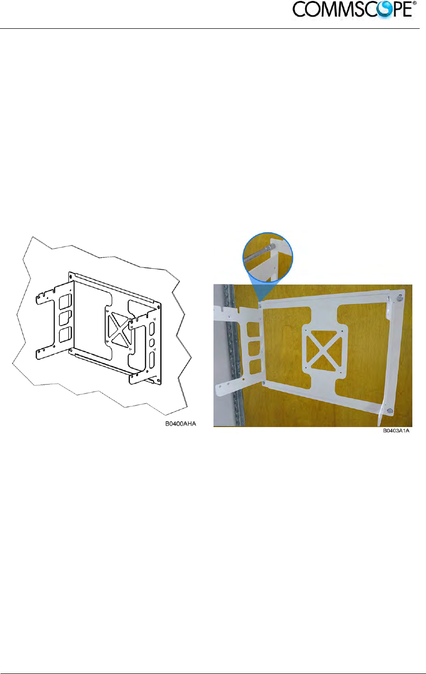
User’s Manual for ION-B Systems
ION-B User Manual (MN024-
15)_n_20150730.docx Page 85
4.10.5.3. Wall-Mounting
1. Check the suitability of the wall-mounting kit and the wall.
2. Install the wall-mounting bracket using 4 M6 screw anchors (not included*) or
suitable lag bolts according to the drilling layout. Confirm that the bracket is
securely fastened to the wall. Installer must verify that the supporting surface will
safely support the combined load of the electronic equipment and all attached
hardware and components.
* The M6 screw anchors are not included as part of the RU delivery because
the suitable type depends on the on-site conditions (wall structure and materials).
Use screw anchors that are appropriate for the mounting surface.
Figure 4-70 Wall-mounting bracket
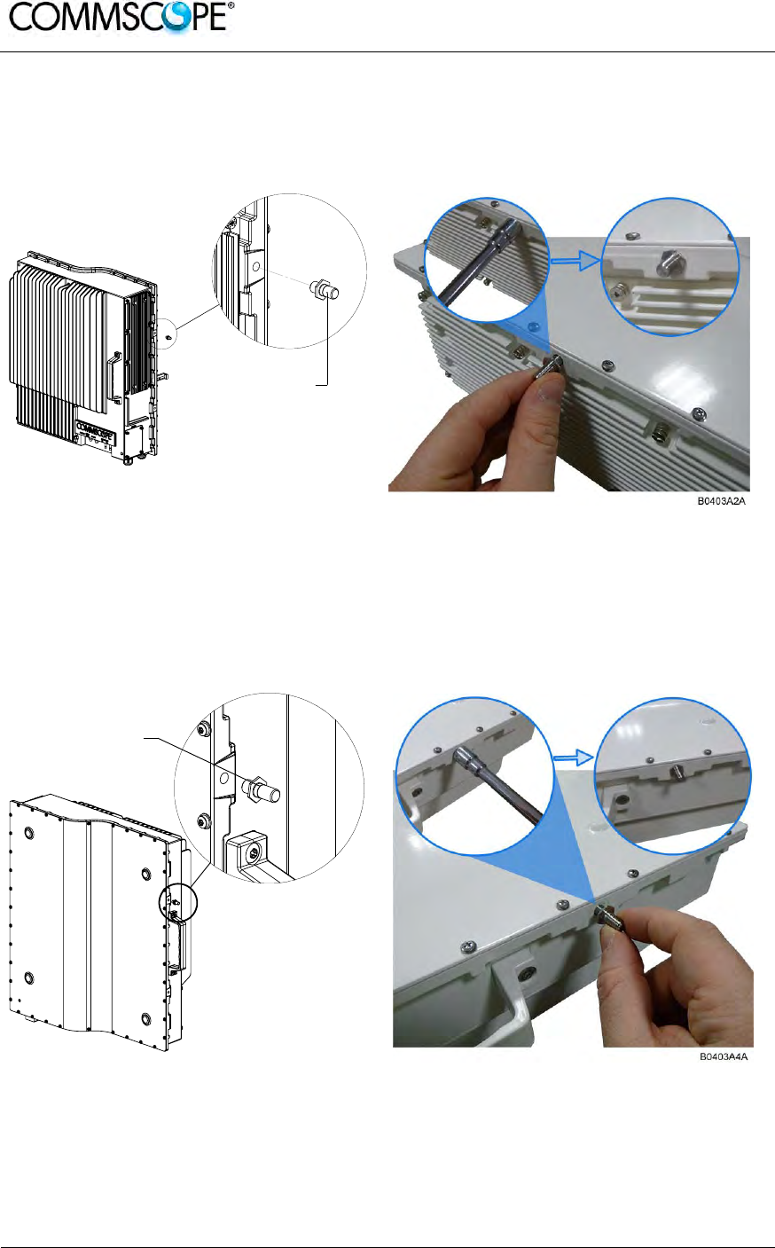
User’s Manual for ION-B Systems
Page 86 ION-B User Manual (MN024-15)_n_20150730.docx
3. Attach an M6 threaded pin to the Remote Unit by inserting it into the threaded
hole adjacent to the power supply and turning it clockwise. Tighten the pin
securely with a socket wrench.
Figure 4-71 RU threaded pin power supply side
4. Attach an M6 threaded pin to the Remote Unit by inserting it into the threaded
hole above the handle and turning it clockwise. Tighten the pin securely with a
socket wrench.
Figure 4-72 RU threaded pin narrow side
M6 threaded pin
B0400AJA
M6 threaded pin
B0403A3A
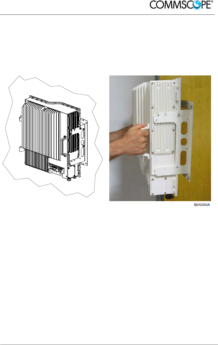
User’s Manual for ION-B Systems
ION-B User Manual (MN024-
15)_n_20150730.docx Page 87
4.10.6. Wall Mounting Procedure
Follow the instructions for mounting the bracket and installing the threaded
pins in chapter 4.10.5.3.
Install the Remote Unit on the wall-mounting bracket by lifting the RU into
place and using both handles and lowering it down onto the bracket. The M6
pins must align with the slots in the bracket to support the RU.
Figure 4-73 Place RU onto wall mounting bracket
B0400AKA
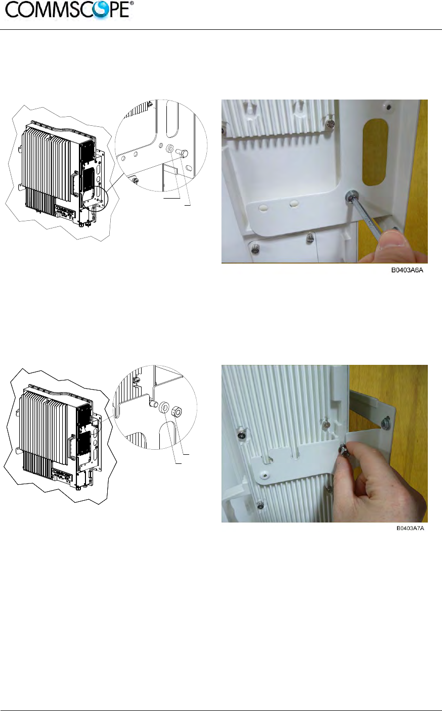
User’s Manual for ION-B Systems
Page 88 ION-B User Manual (MN024-15)_n_20150730.docx
Fasten the lower section of the Remote Unit to the bracket using a washer
and an M6x12 screw (on both sides). Slide a washer over each screw and
then insert the screw and tighten it securely.
Figure 4-74 Install M6x12 screws and washers for single mount
Fasten the Remote Unit to the bracket using a washer and M6 nut. Slide the
washer over the threaded pins that you installed previously (chapter 4.10.5.3)
and then screw the nut onto the pins (on both sides) and tighten securely.
Figure 4-75 Attach M6 nut to threaded pins for single mount
Confirm that all screws and nuts have been fastened and the unit is securely
mounted to the wall.
B0400ALA
M6x12 screw
Washer
B0400AMA
M6 nut
Washer
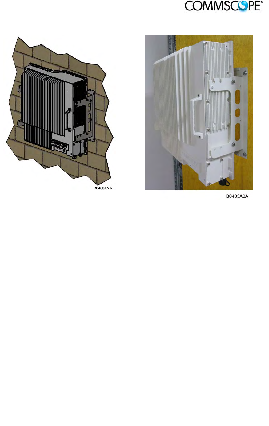
User’s Manual for ION-B Systems
ION-B User Manual (MN024-
15)_n_20150730.docx Page 89
Figure 4-76 Completed RU Mount

User’s Manual for ION-B Systems
Page 90 ION-B User Manual (MN024-15)_n_20150730.docx
4.10.7. TFAx Case U Electrical Installation
4.10.7.1. Health and Safety for Electrical Installation
Read and observe chapter 4.10.2 Health and Safety.
1. Danger: Electrical hazard. Danger of death or fatal injury from electrical
current. Obey all general and regional installation and safety regulations
relating to work on high voltage installations, as well as regulations
covering correct use of tools and personal protective equipment.
2. Danger: Electrical hazard. Danger of death or fatal injury from electrical
current inside the unit in operation. Before opening the unit, disconnect
mains power.
4.10.7.2. Property Damage Warnings for Electrical Installation
1. Attention: It is compulsory to ground (earth) the unit before connecting the
power supply. Grounding bolts are provided on the cabinet to connect the
ground-bonding cable.
2. Attention: If the mains connector of the Remote Unit is not easily accessible, a
disconnect device in the mains power circuit must be provided within easy reach.
3. Attention: A connection of the mains supply to a power socket requires the
power socket to be nearby the Remote Unit.
4. Attention: Before connecting or disconnecting the mains connector at the
Remote Unit, ensure that mains power supply is disconnected.
5. Attention: Make sure that an appropriate circuit breaker acting as a disconnect
device (as required by IEC/EN60950-1) and an overcurrent limiting device are
connected between mains power and the Remote Unit.
6. Attention: Incorrectly wired connections can destroy electrical and electronic
components.
7. Notice: Although the Remote Unit is internally protected against overvoltage, it is
strongly recommended to ground (earth) the antenna cables close to the antenna
connectors of the Remote Unit for protection against atmospheric discharge. In
areas with strong lightning, it is strongly recommended to install additional
lightning protection.
8. Notice: To avoid corrosion at the connectors caused by electrochemical
processes, the material of the cable connectors must not cause a higher potential
difference than 0.6 V (see electrochemical contact series).
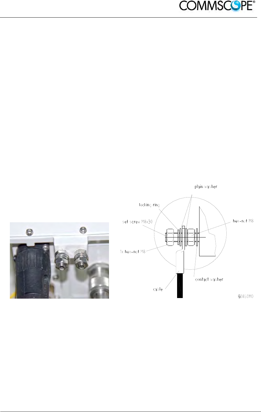
User’s Manual for ION-B Systems
ION-B User Manual (MN024-
15)_n_20150730.docx Page 91
9. Notice: For unstabilized electric networks, which frequently generate spikes, the
use of a voltage limiting device is advised.
10. Notice: The unit complies with the surge requirement according to EN 61000-4-5
(fine protection); however, installation of an additional medium (via local supply
connection) and/or coarse protection (external surge protection) is recommended
depending on the individual application in order to avoid damage caused by
overcurrent.
11. Notice: Observe the labels on the front panels before connecting or
disconnecting any cables.
4.10.7.3. Grounding (Earthing)
The RU must be grounded (earthed).
1. Connect an earth-bonding cable to the grounding bolt(s) connection provided on
the outside of the Remote Unit (near the Mains connector). Do not use the
grounding connection to connect external devices.
Figure 4-77 Grounding bolts Figure 4-78 Grounding bolt, schematic view
2. After loosening the hex nut, connect the earth-bonding cable between the two
washers as illustrated in the figures above.
3. Then, fasten all parts again by tightening the hex nut.
4. Connect the other end of the ground wire to a suitable permanent ground
following local electrical code practices.
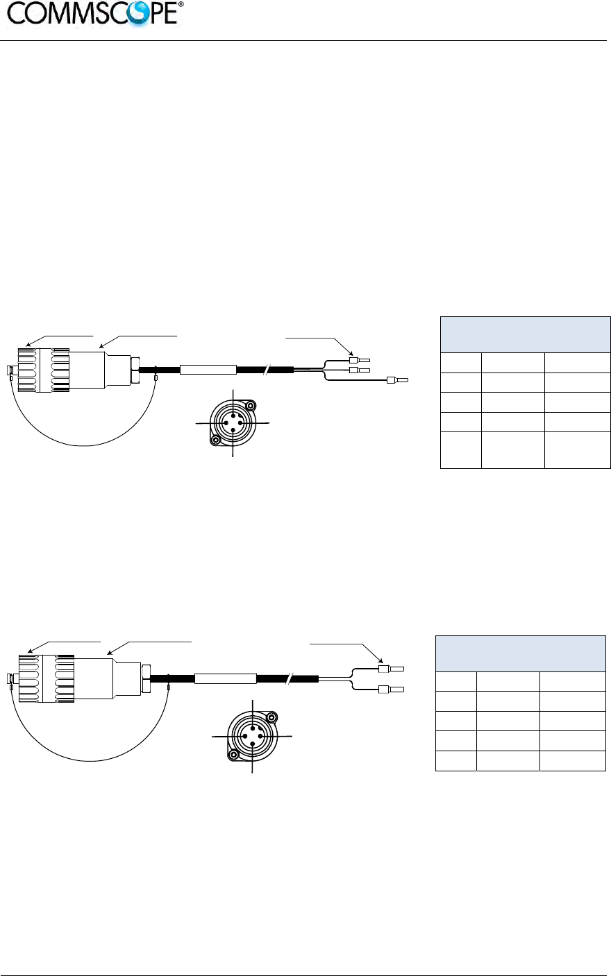
User’s Manual for ION-B Systems
Page 92 ION-B User Manual (MN024-15)_n_20150730.docx
4.10.7.4. Mains Power Connection
Before connecting electrical power to the units, the system must be grounded
(earthed) as described in the previous chapter.
The Mains power must be connected to the Mains connector of the unit for operation
of the RU. A power cable is delivered with each RU. The type of power cable
delivered is dependent on the type of power supply in the RU.
The AC power cable is a 3.2 m (10.5 ft) 16 AWG cable with a 4-pin Amphenol C016
series plug on one end to connect to the RU Mains connector. The other end of the
cable is un-terminated with 3 end splices to connect to the AC power source. A 10 m
(33.7 ft) AC power cable is also available as an option.
4-Pin Amphenol C016
Series
Pin Name Color
1 Phase Brown
2 Neutral Blue
3 n.c. n.c
4 Ground Yellow /
Green
Figure 4-79 AC power cable
table 4-4
AC power cable
The standard DC power cable is a 3.2 m (10.5 ft) 13 AWG cable with a 4-pin
Amphenol C016 series plug on one end to connect to the RU Mains connector. The
other end of the cable is un-terminated with 2 end splices to connect to the -48 Vdc
power source.
4-Pin Amphenol C016
Series
Pin Name Color
1 n.c n.c
2 –48V Black
3 0V Red
4 n.c. n.c
Figure 4-80
DC power cable
table 4-5
DC power cable
The Vdc/100 power cable is available for locations where the power drawn on each
cable must be limited to a maximum of 100 VA. This cable is a 3.2 m (10.5 ft) 16
AWG cable with a 7-pin Amphenol C016 series plug on one end to connect to the RU
Mains connector. The other end of the cable is un-terminated with 4 end splices to
connect to the -48 Vdc power source.
blue
Amphenol 4-Pin
female connector
Protective Cap 3x end splice
brown
yellow / green
B0400A4A
RU Mains
Connector
4
3
2
1
black
Amphenol 4-Pin
female connector
Protective Cap 2x end splice
red
B0400A5A
RU Mains
Connector
4
3
2
1
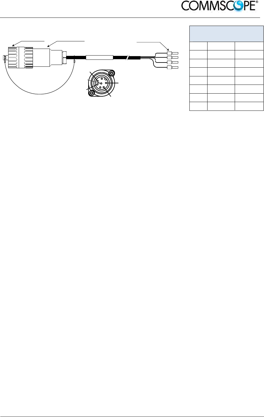
User’s Manual for ION-B Systems
ION-B User Manual (MN024-
15)_n_20150730.docx Page 93
7-Pin Amphenol C016
Series
Pin Name Color
1 0V White
2 –48V Black
3 n.c. -
4 0V Red
5 –48V Green
6 n.c -
7 n.c -
Figure 4-81 Vdc/100 power cable
table 4-6 Vdc/100 power
cable
Notice: For the AC power supply connection, a minimum cross section of 1.5 mm
2
is
required and for the DC power supply connection, a minimum cross section of
2.5 mm
2
is required. Each wire must observe the applicable national regulations
regarding loop impedance, voltage drop, and methods of installation. Make sure
to connect the correct voltage to the unit.
Notice: Do not connect or disconnect the power cable at the mains connector while
power is on. Turn off mains* power before connecting the power cable at the
Remote Unit, then, engage mains power again.
* Mains power must be interruptible with an external mains breaker. For the
mains breaker, observe the following recommendation:
120 Volt / 20 Amp max. or 240 Volt / 16 Amp, single-phase, 50 / 60 Hz AC
service is needed, i.e. the external AC breaker should be 20 Amps max. for
120-Volt service or 16 Amps for 240-Volt service.
For the DC power supply, observe the local regulations of the DC service
provider.
1
2
4
5
7
Amphenol 7-Pin
female connector
Protective Cap 4x end splice
B0400A6
A
RU Mains
Connector
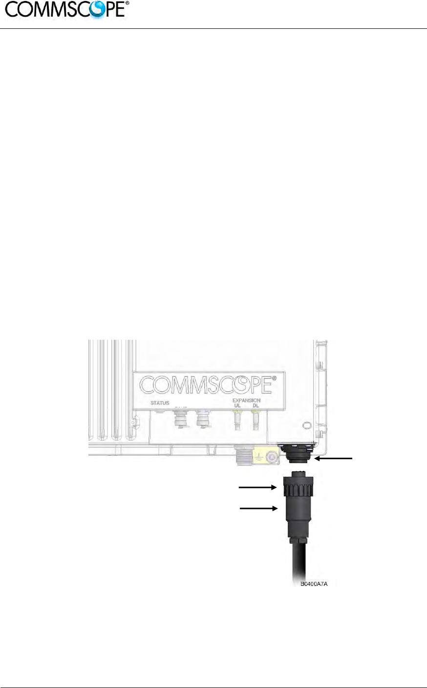
User’s Manual for ION-B Systems
Page 94 ION-B User Manual (MN024-15)_n_20150730.docx
Use the following method to install and connect the Mains power to the RU:
1. Locate the Mains power cable that was delivered with the RU.
2. Locate or install a suitable power junction box or receptacle near the RU and
route the power cable from the power source to the RU. Do not connect the
cable to the RU’s Mains connector at this time. The power source must be
interruptible.
3. The Mains cable must be properly secured observing local regulations and
electrical codes. Be sure to allow enough slack in the cable at the RU to plug
or unplug the cable into the Mains connector of the RU.
4. Wire the power cable to the junction box or receptacle. Refer to the color code
and pin numbers depending on the type of power supply used by the RU.
5. With the cable’s Mains plug disconnected from the RU, turn the circuit breaker
on, unscrew the plug’s protective cover, and carefully test the plug with a
voltmeter to ensure that the voltage and polarity are correct.
6. Once the testing has been completed, turn off the circuit breaker.
7. Unscrew the protective cover from the Mains connector of the RU.
8. Insert the plug into the Mains connector and tighten the clamping ring until it is
hand tight. Do not over-tighten the clamping ring.
Figure 4-82 Connect Mains plug
Clamping ring
Mains plug
Mains
connector

User’s Manual for ION-B Systems
ION-B User Manual (MN024-
15)_n_20150730.docx Page 95
4.10.7.5. Antenna Connection
The Remote Unit has one N-type antenna connector(s). For mounting the cable
connector, it is recommended to refer to the corresponding documentation of the
connector manufacturer. The bending radius of the antenna cables must remain
within the given specifications.
The selection of cable and antenna is an important consideration. On the one hand, a
cable with higher loss is less expensive but, on the other hand, it impairs
performance.
Notice: Use an appropriate torque wrench for the coupling torque of N-type
connectors (2 N-m / 1.5 ft lb with 13/16 in opening to tighten the N-type antenna
connectors. For example, use torque wrench of item no. 244379 available from
the CommScope e-catalog. Do NOT use your hands or any other tool (e.g. a pair
of pliers)! This might cause damage to the connector and lead to a malfunction of
the Remote Unit.
Notice:To minimize passive inter-modulation (PIM) distortion, attention must be paid
to the physical condition of the connector junctions. Do not use connectors that
show signs of corrosion on the metal surface. Prevent the ingress of water into
the connector. Attach and torque the connectors properly.
1. Route the antenna cable from the antenna or splitter to the base of the RU.
2. Cut the cable to length and terminate the cable with an N-type male
connector.
3. Remove the red plastic protective cover from the N-type female connector.
4. Using an appropriate torque wrench, connect the cable to the antenna port of
the RU.
Figure 4-83 Antenna connection
Antenna connector
Antenna cable

User’s Manual for ION-B Systems
Page 96 ION-B User Manual (MN024-15)_n_20150730.docx
4.10.7.6. Alarm Ports
The Alarm port provides alarm contacts that are used to report alarms generated by
the RU to external equipment. The connector is a 5-pin Binder 712 series connector.
5-Pin Binder 712
Series
Pin Assignment
1 EXT1_Alarm
2 EXT1_GND
3 n.c.
4 EXT2_Alarm
5 EXT_GND
Figure 4-84 Alarm Connector
table 4-7 Alarm
Connector
4.10.8. Low Power RU Optical Installation
4.10.8.1. Optical-Fiber-Cable Connection - Rules
Main optical system parameters:
Fiber:
Single mode fiber, type is 9.5/125 µm
Fiber-cable connectors LC/APC
ION-U system:
Note: The pigtails for the connection between Master Unit and Remote Unit
must have a sufficient length. Protection for the optical fibers must be
provided where the fibers feed into the units.
Note: The system attenuation of the optical fibers, including the connectors,
must not exceed 5 dB.
System attenuation and attenuation of optical components must be determined. This
can be achieved by measuring attenuation and reflection with an appropriate
measuring instrument. For pigtails, a total value of < 0.4 dB (measured to a reference
plug) can be assumed due to the dead zone of the reflectometer. These
measurements must be made with a sufficient length of optical fiber, at the input and
output of the device which has to be measured.
51
B0400AZA

User’s Manual for ION-B Systems
ION-B User Manual (MN024-
15)_n_20150730.docx Page 97
Fiber-System Installation:
Fiber-cable connectors have to be of the same type (LC/APC) as the connectors
used for the unit. The fiber-optic cables are connected to the optical transceiver.
Notice: Angled connectors are not compatible with straight optical connectors; non-
compatibility of connectors will result in permanent damage to both connectors.
Before connecting the fiber cables, follow the procedure below to ensure optimized
performance. It is important for these procedures to be carried out with care:
Remove fiber-optic protective caps just before making the fiber connections.
Do not leave any LC/APC connectors open as they may attract dirt. Unused
optical connectors must always be covered by their caps.
Do not bend the fiber-optic cable in a tight radius (< 5 cm) as this may cause
damage to the cable and interrupt transmission.
Using high-grade alcohol and lint-free cotton cleaning swabs, clean the end of
the fiber-optic cable that will be inserted in the optical connectors on the donor
interface box. Use a fiber end-face inspection tool to scan both, the class fiber
and its surrounding area.
Check for dirt on the cladding, chips/pits, dirt on the ferrule, and scratches.
Connect the fiber-optic cables by inserting the cable end into the laser
receptacle.
Do not use any index-matching gels or fluids of any kind in these connectors.
Gels are intended for laboratory use and attract dirt in the field.
Note: Care should be taken when connecting and disconnecting fiber-
optic cables - use the connector housing to plug or unplug a fiber.
Scratches and dust significantly affect system performance and
may permanently damage the connector. Always use protective
caps on fiber-optic connectors not in use.
Cleaning Procedure for Fiber-Optical Components:
Any contamination in the fiber connection results in additional optical transmission
loss which could cause whole system failure. It is thus recommended that every fiber
connector be inspected and cleaned prior to mating.
The goal is to eliminate any dust or contamination and to provide a clean
environment for the fiber-optic connection.
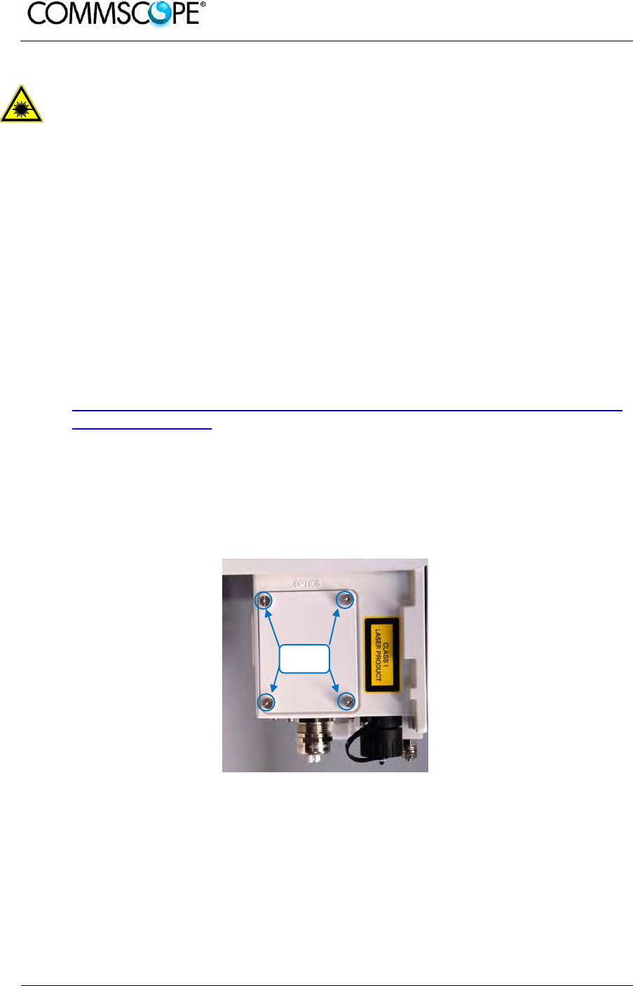
User’s Manual for ION-B Systems
Page 98 ION-B User Manual (MN024-15)_n_20150730.docx
When you clean fiber components, always complete the following steps carefully:
Caution: Laser radiation. Risk of eye injury in operation. Do not stare into the
beam; do not view it directly or with optical instruments.
1. Turn off the ION-U system (laser sources) before you inspect fiber connectors.
2. Check the connectors or adapters with a fiberscope before cleaning.
3. If the connector is dirty, clean it with a lint-free wipe (dry cleaning).
4. Inspect the connector.
5. If the connector is still dirty, repeat the dry cleaning technique.
6. Inspect the connector.
7. If the connector is still dirty, clean it with 99% isopropyl alcohol (wet cleaning)
followed immediately with a dry clean in order to ensure no residue is left on
the surface.
8. Repeat steps 5 through 7 until surface is clean.
Note: For a more detailed description, please refer to:
http://www.cisco.com/en/US/tech/tk482/tk876/technologies_white_paper09186
a0080254eba.shtml
4.10.8.2. Optical cable installation
1. Locate the Optics connector cover on the lower right side of the RU. Loosen
the four cover screws, remove the cover, and set it aside. Removing this cover
allows access to the UP and DL optical connectors.
Figure 4-85 Remove optics cover
Cover
Screws
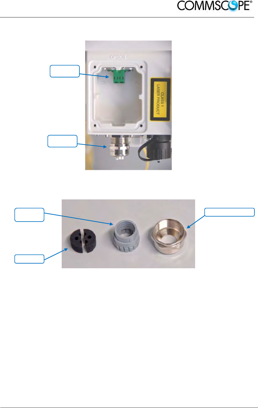
User’s Manual for ION-B Systems
ION-B User Manual (MN024-
15)_n_20150730.docx Page 99
2. Remove the sealing nut from the optical cable gland at the bottom of the RU.
Figure 4-86 Remove sealing nut
3. Remove the split-seal and clamp jacket.
Figure 4-87 Split-seal and clamp jacket
4. Insert the optical cables through the sealing nut and the clamp jacket.
5. Then insert the optical cables through the opening in the cabinet.
Sealing
nut
Split-seal
Sealing nut
Optical
connectors
Clamp
jacket
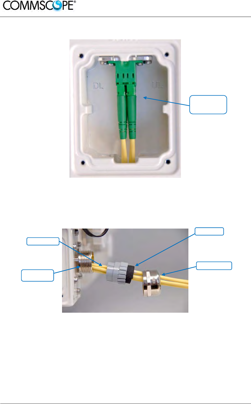
User’s Manual for ION-B Systems
Page 100 ION-B User Manual (MN024-15)_n_20150730.docx
6. Connect the optical cables to the proper UL and DL LC/APC connectors.
Figure 4-88 Optical cables connected
7. Separate the two halves of the split-seal. Place one cable into the hole and the
other in the groove of each half of the split-seal. Insert the spit seal into the
clamp jacket.
Figure 4-89 Place cables into split-seal
Split-seal
Clamp jacket
Connect
LC/APC optical
cables
Sealing nut
Connector
socket

User’s Manual for ION-B Systems
ION-B User Manual (MN024-
15)_n_20150730.docx Page 101
8. Insert the clamp jacket with split seal to the connector socket and fasten them
with the sealing nut.
Figure 4-90 Optical cable installed
9. Replace the optics metal cover and tighten the four screws that were
loosened in step 1.
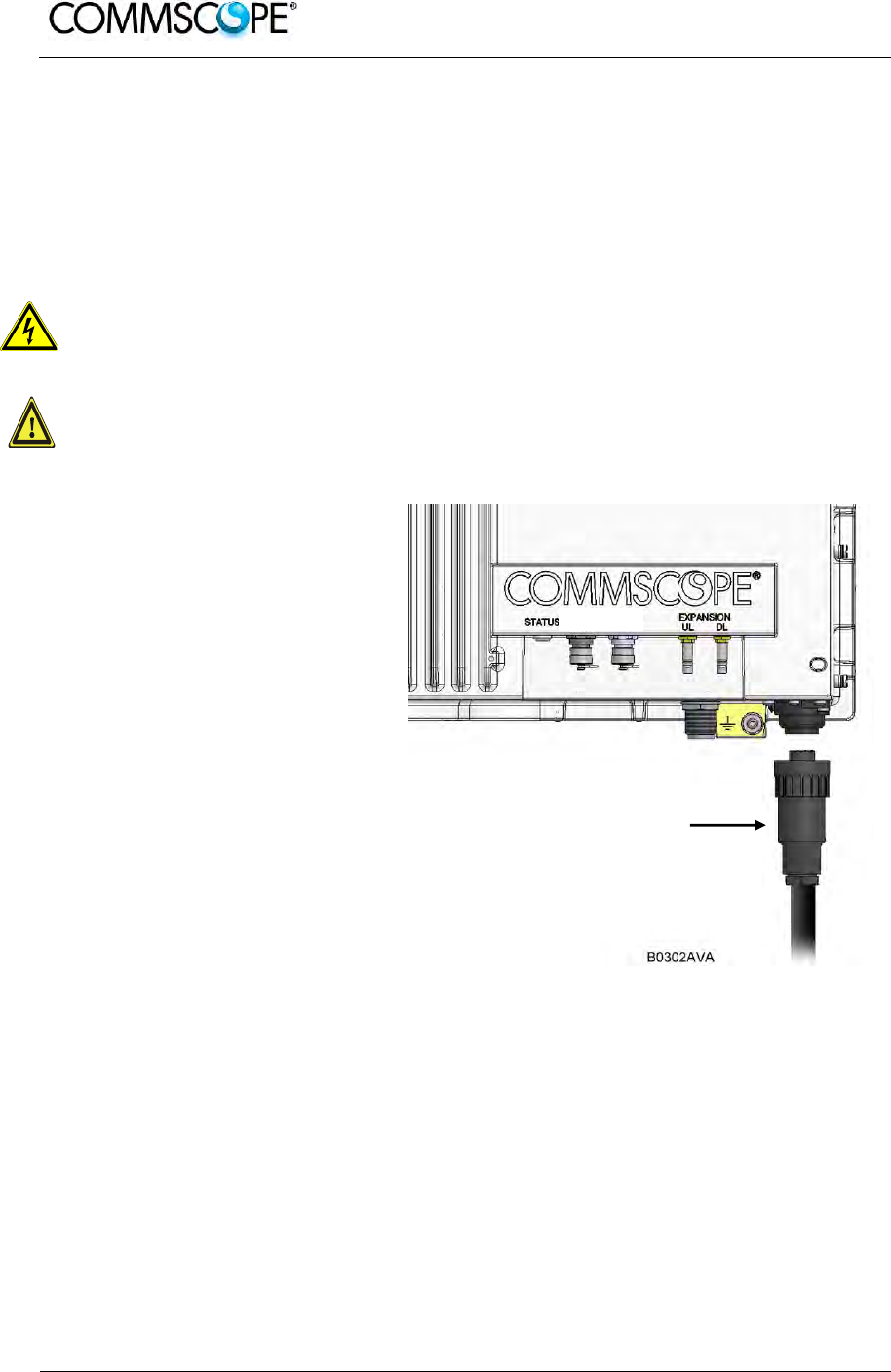
User’s Manual for ION-B Systems
Page 102 ION-B User Manual (MN024-15)_n_20150730.docx
4.10.8.3. RU Power Supply Replacement
The power supply for the RU is a field replaceable module. The type of power supply
used by the RU (AC, DC, or Vdc/100) is dependent on the model number of the RU.
Attention: Before starting any maintenance on the RU, read and observe
chapter
4.10.2 Health and Safety and the electrical installation information in chapter
4.10.7.1 Health and Safety for Electrical Installation.
1. Danger: Electrical hazard. Danger of death or fatal injury from electrical
current inside the unit in operation. Before opening the unit, disconnect
mains power.
2. Caution: The unit reaches high temperature in operation. Risk of burns by
hot surface. Do not touch the unit before it has sufficiently cooled down.
1. Switch off the circuit breaker
supplying power to the RU.
2. Once you have confirmed that
the power has been shutdown,
remove Mains power
connector from the RU.
Figure 4-91 Disconnect Mains power
Mains plug
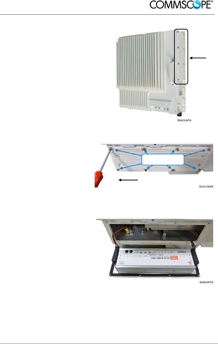
User’s Manual for ION-B Systems
ION-B User Manual (MN024-
15)_n_20150730.docx Page 103
3. Locate the power supply on
the right side of the Remote
Unit.
Figure 4-92 RU power supply location
4. Use a #2 Phillips head or
slotted screwdriver to loosen
the 8 universal slot/Phillips
captive power supply screws
and carefully remove the
supply. The weight of the
power supply must be
supported as you loosen the
screws to prevent damage to
the supply.
Figure 4-93 8 RU power supply screws
5. Carefully remove the power
supply from the unit. Do not
attempt to support the weight
of the supply with the attached
input and output cables.
Figure 4-94 RU power supply with cables
Mains
connecto
r
Power
supply
Loosen 8 universal
slot/Phillips screws
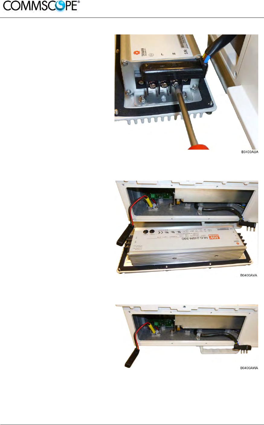
User’s Manual for ION-B Systems
Page 104 ION-B User Manual (MN024-15)_n_20150730.docx
6. Locate the input cable
connector for the power
supply on the right side of the
supply.
7. Loosen the 3 Phillips head
terminal screws and remove
the connector.
Figure 4-95 RU power supply input cable
8. Locate the output connector
for the power supply on the
left side of the supply.
9. Loosen the 2 Phillips head
screws and remove the output
connector.
Figure 4-96 RU power supply output cable
10. Remove the defective supply.
Figure 4-97 RU with power supply removed

User’s Manual for ION-B Systems
ION-B User Manual (MN024-
15)_n_20150730.docx Page 105
11. Replace the defective power
supply with the new power
supply.
It is very important to confirm
that the replacement supply is
the same type as the original
supply. The AC, DC, and
Vdc/100 supplies are not
interchangeable.
12. Reconnect the input and
output connectors, and tighten
the associated terminal
screws.
Figure 4-98 RU with replacement power supply
13. Insert the power supply into
the RU carefully to avoid
damaging any cables. The
supply must be supported until
the 8 universal slot/Phillips
captive power supply screws
have been tightened.
14. Tighten the 8 universal
slot/Phillips captive power
supply screws.
Figure 4-99 RU insert power supply

User’s Manual for ION-B Systems
Page 106 ION-B User Manual (MN024-15)_n_20150730.docx
15. Reconnect the Mains power
plug.
16. Switch on the breaker and
check the RU for proper
operation.
Figure 4-100 Reconnect Mains power

User’s Manual for ION-B Systems
ION-B User Manual (MN024-
15)_n_20150730.docx Page 107
4.11. REMOTE UNIT START-UP
Before switching on the Remote Unit, make sure that:
• the modules hosted in the Master Unit have been connected each other with RF
jumpers, according to the system design
• every TFLN master optical TRX has been connected to its Remote Units
• each Remote Unit has been connected to its coverage antennas
Note: For a correct system start-up, all Remote Units have to be switched
on before the Master Unit.
Once the Remote Unit has been switched on, its behaviour could be checked by
looking at the control LEDs. When the system starts-up, their status can be
summarized by the following steps:
1. When the Remote Unit is turned on, both the LEDs turn on for a couple of
seconds.
2. After that, the unit green LED remains on (thus indicating proper power supply),
while the red LED switches off as soon as the TFLN Master optical TRX is
turned on (meaning that DL optical power is OK and no alarms are present).
3. Once the TFLN Master optical TRX has been switched on, if the red LED
remains on, please refer to the troubleshooting section.
4. After being switched on the RU in order to be recognized by the supervision
management system the corresponding TFLN Master optical TRX must carry
out the discovery phase (please refer to the Supervision System Manual for
more details). During this phase (which lasts up to maximally four minutes
depending on the system complexity) the TFLN LED blinks. Do not
connect/disconnect any cables or pieces of equipment during the discovery
phase! This may result in the identification failure of the RU.
Note: In case discovery does not start automatically, check through either
the LMT or the Remote Supervision if the Remote Unit / discovery
has been disabled (refer to LMT or Remote Supervision System
manuals for further information).
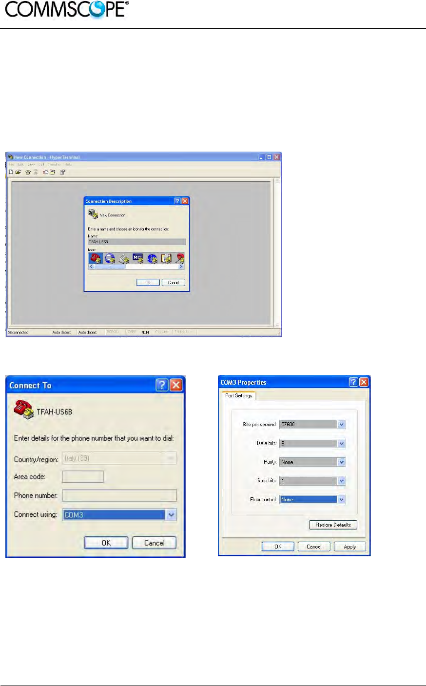
User’s Manual for ION-B Systems
Page 108 ION-B User Manual (MN024-15)_n_20150730.docx
4.12. CASE R2, R2E, AND R4E REMOTE UNIT SETTINGS THROUGH RS232
You can get or set information of Remote Units in case R2 and R2E through a local
connection to the RS232 port. This can be done through the HyperTerminal (a
program available by default in Windows)
The below described steps have to be followed:
1. Save the HyperTerminal connection in order to recall it when needed
2. Choose a COM port and configure it as per below
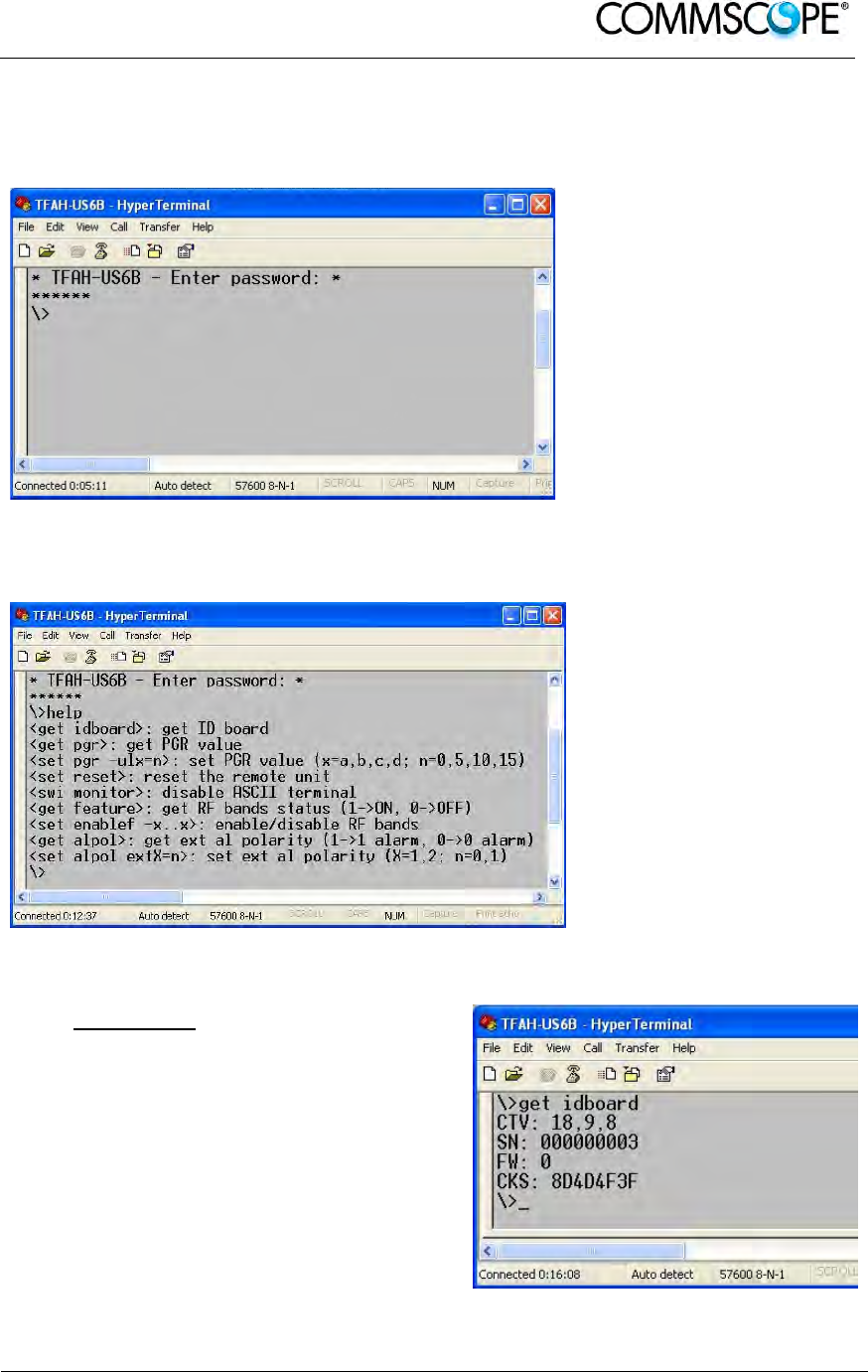
User’s Manual for ION-B Systems
ION-B User Manual (MN024-
15)_n_20150730.docx Page 109
3. Plug the laptop to the RS232 port of the Remote Unit and press ENTER
Type the password “andrew” and press ENTER to login.
If you don’t press any key the Remote Unit will logout after 2 minutes.
4. Type “help” and press ENTER to have a brief list of the supported commands
for the Remote Unit you have
5. The possible commands have been described in the following.
get idboard
Shows the identification data of the
unit:
CTV: class, type, version
SN: serial number
FW: firmware revision
CKS: firmware checksum
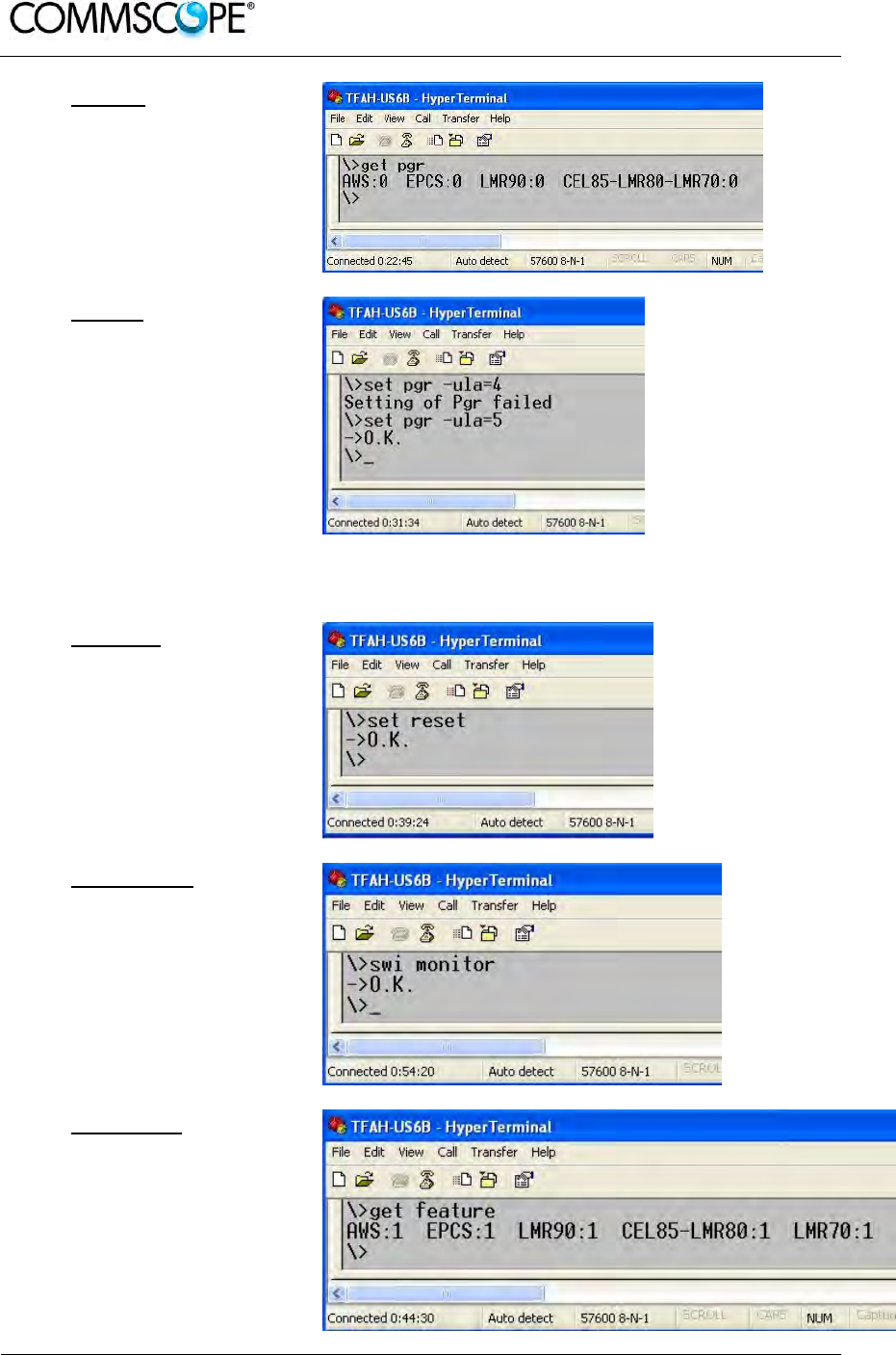
User’s Manual for ION-B Systems
Page 110 ION-B User Manual (MN024-15)_n_20150730.docx
get pgr
Shows the values of
pgr attenuators for
each band.
set pgr
It let change the pgr
values, one band each
command.
The possible values
are 0, 5,10,15 dB.
Examples of the
command syntax are:
“set pgr –ula=5” for
AWS
“set pgr –ulb=5” for
EPCS
set reset
Performs a software
reset of the unit
swi monitor
Disables ASCII
protocol.
get feature
Shows the status of the
bands of the unit (1-
>enabled; 0->disabled).
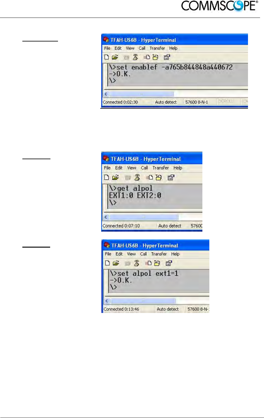
User’s Manual for ION-B Systems
ION-B User Manual (MN024-
15)_n_20150730.docx Page 111
set enablef
Let enable/disable the
bands of theunit.
The command syntax
is: “set enable -
xxxxxxxxxxxxxxxxxxx”
where x is the
hexadecimal digit of a
code provided by the
factory given the SN of
the unit
The command become
operative only after
reset
get alpol
Shows the
configuration of
external alarm
connectors.
1-> high level alarm,
low level not alarm
0-> low level alarm,
high level not alarm
set alpol
Let change the polarity
of external alarm.
The command syntax
is: “set alpol ext1=1”
“set alpol ext2=1”
1-> high level alarm,
low level not alarm
0-> low level alarm,
high level not alarm

User’s Manual for ION-B Systems
Page 112 ION-B User Manual (MN024-15)_n_20150730.docx
4.13. TROUBLESHOOTING
4.13.1. List of All Alarms
Errors are indicated by LEDs on the TFAx front panel, as well as by LMT or the
Supervision System (running on the remote supervision unit). Both the LMT and the
Supervision System can provide complete information about the cause of the alarm.
As a consequence, troubleshooting is faster if failure detection is carried out directly
through either the LMT or the Supervision System.
ION-B modules are designed to exchange information, meaning that each RU can
receive failure notifications from its external equipment through alarm connections.
Moreover, the TFAx constantly monitors the optical signal received from its TFLN unit
to control optical losses.
The following table shows a brief description of the possible alarms related to a RU,
with reference to the corresponding alerted LEDs and to the actions to be carried out
in case of a fault. Remote units can have a sub-set of the below alarms.
ALARM CODE
(TSUN) ALARM DESCRIPTION ACTIVE
LED
SUPERVISION
PRIORITY LEVEL
ACTION
RECOMMENDED
RELÉ PRIORITY
LEVEL (subrack)
Antenna DC loop alarm ALWAYS OK
DL optical power fail
1
The optical power received on the
DL is too low and can not be
compensated RED MAJOR Check the DL fibre
and the TFLN laser
status MAJOR
AGC out of range
1
The optical power received is under
the allowed 3dB optical loss but it
can be compensated NONE WARNING Clean optical
connectors MINOR
DL RF alarm
in Band x
(one for each RU band)
HW failure on the DL low band RF
section RED CRITICAL Return the unit MAJOR
WiMax Synchronization
Lost alarm The synch signal is not present RED MAJOR Check the master
unit synch signal. If it
is ok return the unit MAJOR
External 1 alarm Alarm on the device connected to
alarm-contact 1 RED MAJOR Check external
device or alarm
connection MAJOR
External 2 alarm Alarm on the device connected to
alarm-contact 2 RED MAJOR Check external
device or alarm
connection MAJOR
Power supply alarm UPS HW failure or malfunction.
RF is turned OFF RED MAJOR Check external PSU.
If it works properly,
replace the unit MAJOR
Internal BUS alarm A malfunctioning on the digital part
involves a fault in monitoring
functionalities RED CRITICAL Return the unit MAJOR
Sensor fail An I
2
CBUS failure may result in a
wrong temperature reading NONE MINOR Return the unit MINOR
Temperature alarm Over-temperature alarm NONE WARNING Check ventilation
and environment MINOR
1
See chapter 4.3.10 Automatic Gain Control (AGC)
table 4-8 Remote Unit Alarms

User’s Manual for ION-B Systems
ION-B User Manual (MN024-
15)_n_20150730.docx Page 113
As the table shows, minor alarms (low priority alarms) are indicated only by either the
LMT or the Supervision System, and not through LEDs. Minor alarms detect critical
situations which should be checked and tested in order to avoid future possible
system faults.
The troubleshooting procedures are described in the following chapter and shown in
Figure 4-101 Troubleshooting overview
4.13.2. Quick Troubleshooting
If the red LED is ON, please follow these steps:
1. Refer to Alarm Relay-Contact Troubleshooting section in order to discover
whether or not the alarm is a result of external equipment failure.
2. If alarm-contact troubleshooting has not cleared any failures, clean the optical
connectors.
3. If the problem still persists, refer to section to see if the optical cables or
connections have any problems along the DL path.
4. If none of the previous actions served to switch off the LED, replace the unit with
a new one or contact for assistance.
4.13.3. Alarm Relay-Contact Troubleshooting
This procedure should be considered if at least one TFAx alarm-contact is connected
to any external equipment. If not, return to main troubleshooting procedure.
These steps aim to detect any failure inside external equipment or alarm-contact
ports. If the alarm-contacts troubleshooting cannot clear any equipment malfunctions
or port failures, then return to the main troubleshooting procedure.
For any alarm-contact that is connected to external equipment, follow these steps:
1. Disconnect it, and check the TFAx LED status after the disconnection.
2. If the red LED has switched off, any external equipment that is connected to the
alarm-contact port is probably faulty. Please test it.
3. If the TFAx red LED still remains on after the disconnection, measure the
voltage between the terminals of the alarm-contact port.
a) If the terminals are electrically closed, the alarm-contact port is faulty.
Contact the manufacturer for assistance.
b) If the terminals are open, this means neither the analysis of the present
alarm-contact nor the one of its external equipment has revealed failures.
Re-connect the present alarm-contact port to its external equipment. If the
TFAx has any other unchecked alarm-contacts connected to external
equipment, apply the whole procedure (i.e. steps 1-3) to this port.

User’s Manual for ION-B Systems
Page 114 ION-B User Manual (MN024-15)_n_20150730.docx
4.13.4. Fibre-Optic DL Troubleshooting
1. Check to see if there are any points in which fibres are experiencing a short
radius of curvature. In these cases, rearrange the optical path in order to avoid
sharp bends (if necessary, replace the optical cable with a longer one).
2. Check to see if SC-APC connectors are properly installed at both fibre ends. In
case they are not, re-plug the SC-APC connectors to adapters.
3. Disconnect the optical fibre and clean it at both ends, then clean the SC-APC
ports on both the TFLN and the RU. Re-connect the fibre to relevant ports after
cleaning.
4. Disconnect the optical SC-APC connector from the Remote Unit’s DL port, and
measure the output power P
OUT
(DL) at the corresponding fibre end. Then, go to
the TFLN side, disconnect the optical SC-APC connector from the TFLN DL port
and measure the input power P
IN
(DL) coming out of the TFLN DL port. Calculate
the DL fibre attenuation ADL as ADL [dB] = P
IN
(DL) – P
OUT
(DL):
a) If ADL > 4dB, then there are problems with the fibre optic cable. Replace it
with a new one.
b) If ADL < 4dB, the troubleshooting procedure has not identified the problem.
Refer to the Supervision System or contact assistance.
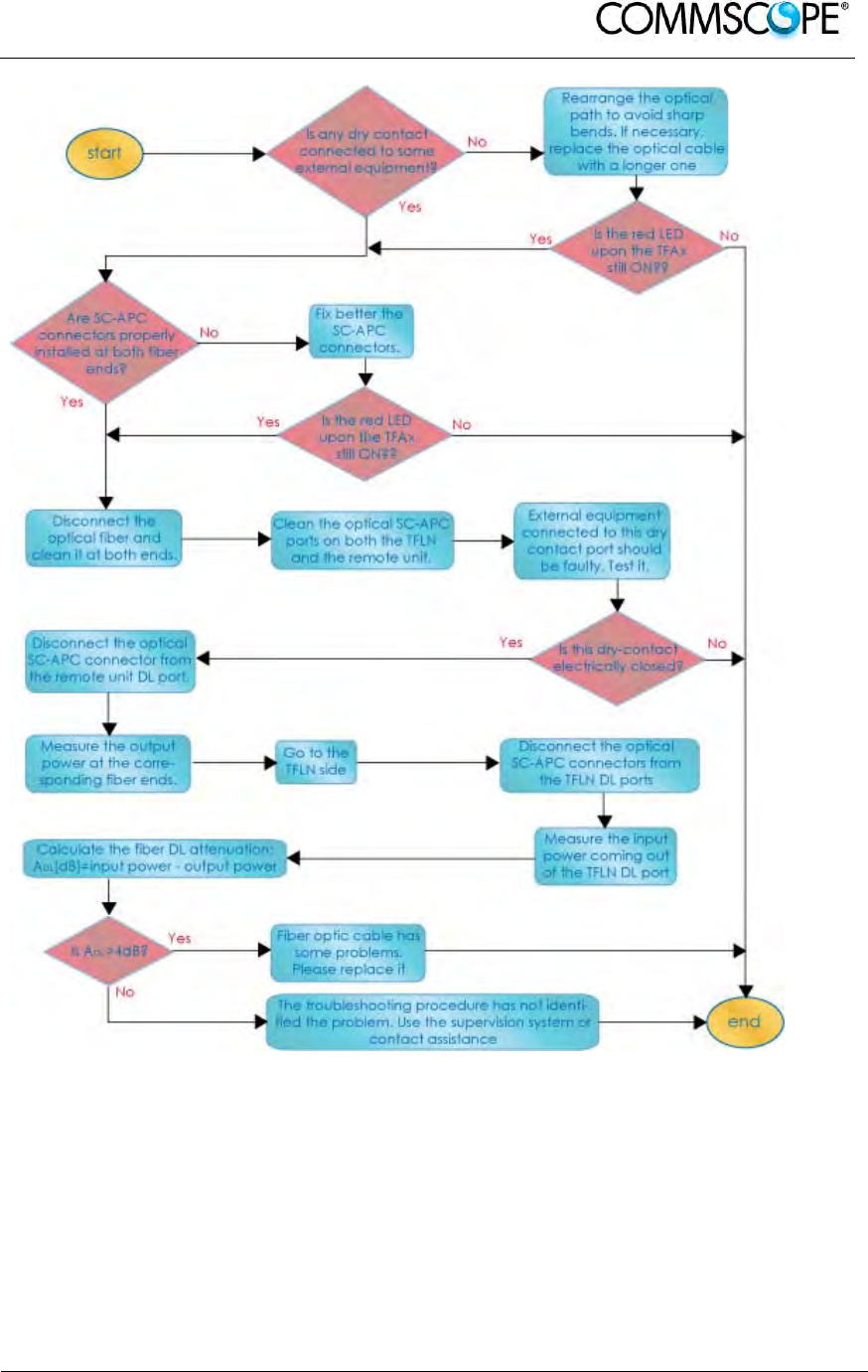
User’s Manual for ION-B Systems
ION-B User Manual (MN024-
15)_n_20150730.docx Page 115
Figure 4-101 Troubleshooting overview

User’s Manual for ION-B Systems
Page 116 ION-B User Manual (MN024-15)_n_20150730.docx
5. TFBX BOOSTER
5.1. THE MAIN TASKS OF THE TFBX BOOSTER
Downlink (DL):
• RF output power adjustment: to compensate the gain variation of the auxiliary
channel
• RF amplification: RF signal are boosted in order to maintain a good signal-to-
noise ratio
• RF filtering: a proper filter rejects the spurious emissions
• RF splitting: the boosted RF signal is conveyed to two antenna ports
Uplink (UL):
• Automatic Level Control (ALC): the RF signal level is adjusted according to
blocking requirements
• RF amplification: a low noise amplifier boosts the signal received from antennas
in order to maintain a good signal-to-noise ratio
• RF filtering: the boosted signal is cleaned of the spurious emissions
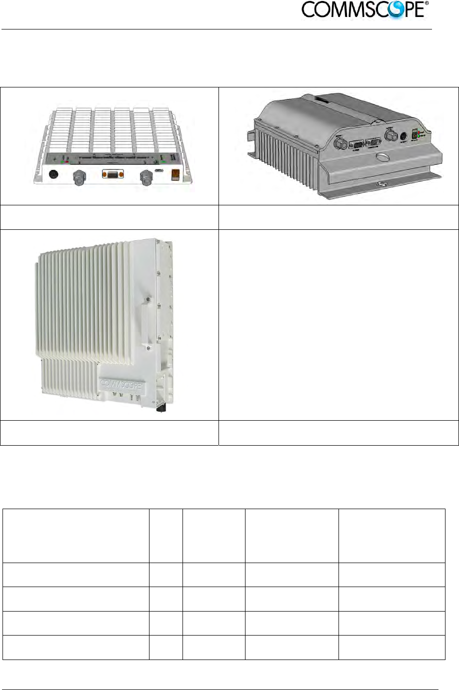
User’s Manual for ION-B Systems
ION-B User Manual (MN024-
15)_n_20150730.docx Page 117
5.2. DIFFERENT TYPES OF BOOSTERS
To ease the system expansion to serve different bands, boosters can be connected
to the auxiliary channel of the Remote Units.
Figure 5-1 Case B Booster Figure 5-2 Case R2 Booster
Figure 5-3 Case U Booster
Depending on the bands where radio coverage has to be provided and on the signal
power required to cover the environment, the topology / case type of the booster will
be determined.
Product
Code
Case
RF Port
Power
Supply
Bulletin
Code
TFBM7 B
1 or 2
(dip switch) TPSN1/28-80
TPSN3/28-80 PA-103494-EN
TFBM17 B
1 or 2
(dip switch) TPSN1/28-80
TPSN3/28-80 PA-102073-EN
TFBM7/7 R2 2
TPSN1/28-80
TPSN3/28-80 PA-103794-EN
TFBH23/23 U 2
RPS150-Vac
RPS150-Vdc see Commscope
eCatalog
table 5-1 Booster Reference Table

User’s Manual for ION-B Systems
Page 118 ION-B User Manual (MN024-15)_n_20150730.docx
5.3. WARNINGS (TO BE READ BEFORE BOOSTERS ARE INSTALLED)
The warnings listed below refer to all boosters. Please read them carefully before
starting the installation.
5.3.1. Choosing a Proper Installation Site for the booster
• TFBx booster have to be installed as close as possible to the Remote Unit and
to the radiating antennas, in order to minimize coaxial cable length, thus
reducing downlink power loss and uplink noise figures.
• When positioning the TFBx booster, be sure to place related antennas in such
a way as to minimize the minimum coupling loss (MCL), in order to avoid
blocking.
• The TFBx booster is designed to be fastened to walls, ceilings, or other flat
surfaces (TKA installation kits are available; they provide a protective cover for
the TFBx boosters, while making installation easier and faster).
5.3.2. Correct Positioning of the Booster and its Power Supply
• Under no circumstances should any component be affected by the heat
created by any other one. The booster and its external power supply should be
mounted so as to avoid reciprocal heating. Side-by-side configuration is
suggested.
• Boosters are provided with cooling fins which allow the optimization of heat
dissipation. To ensure proper operation the mounting environment should
allow for the necessary air flow.
• It is strongly recommended not to mount the external power supply on a
horizontal surface because this position does not allow heat dissipation.
External power supplies must be mounted on vertical surfaces.
• In order to assure proper heat dissipation, external power supplies must be
mounted in a vertical position with the power socket downwards.
5.3.3. Power Supply
The TFBx boosters are provided with different types of TPSN external power
supplies (TFBH: internal power supply), available either for universal mains (90 to
264 Vac) or for negative supply (-60 to -36 Vdc). Different power ranges are
available, see table 5-1 Booster Reference Table.
Figure 5-4 220 Vac/+28Vdc power
adapter
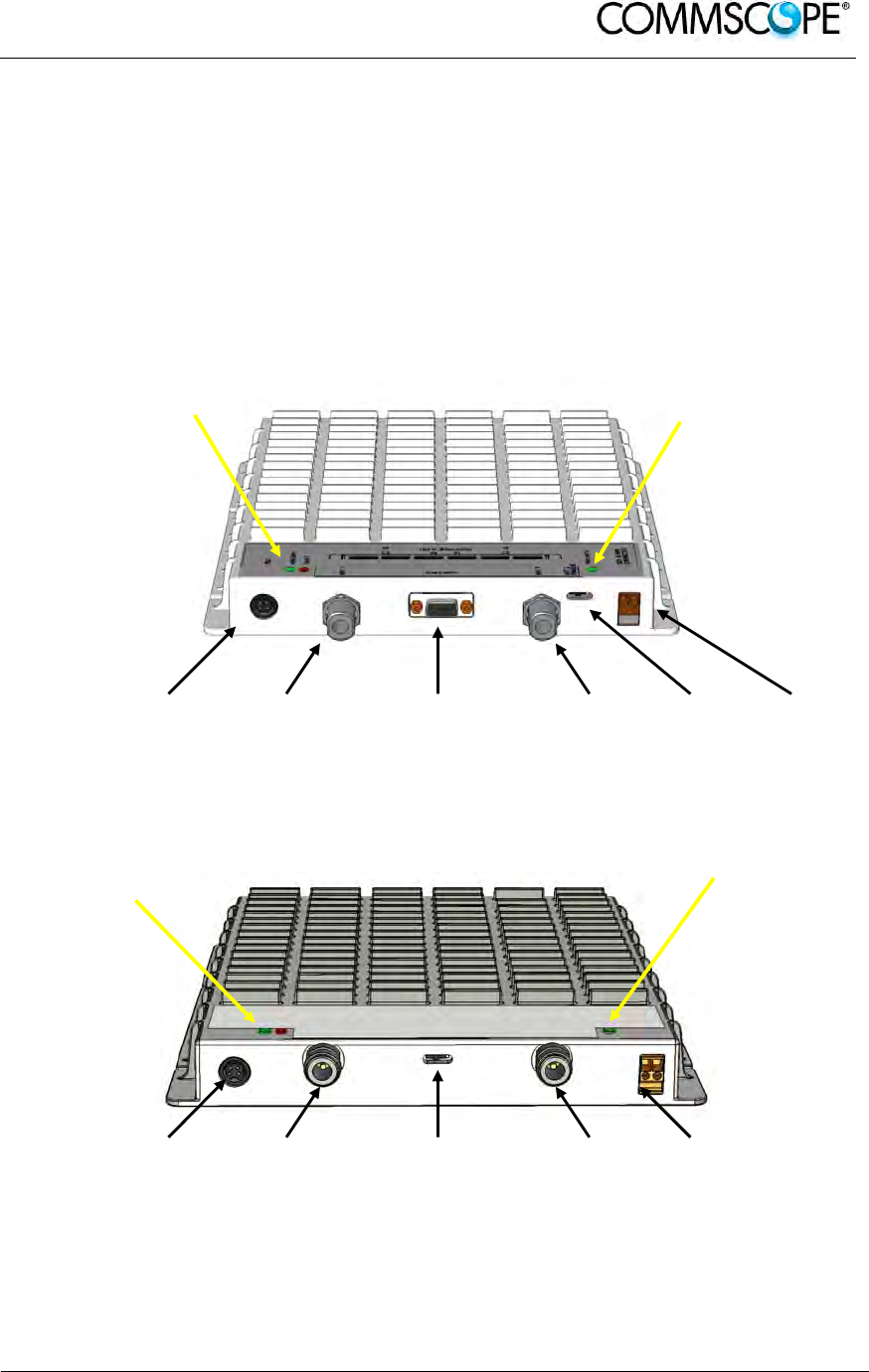
User’s Manual for ION-B Systems
ION-B User Manual (MN024-
15)_n_20150730.docx Page 119
5.4. CASE B BOOSTER
5.4.1. Specifications
Dimensions: 38 x 240 x 240 mm
(1.5 x 9.4 x 9.4 inches)
Weight: Please refer to the TFBM dedicated bulletin in order to discover any
updated data regarding the weight of a specific Case B TFBx.
Power supply
connector RF
antenna
port 1
RS232 Port RF
antenna
port 2
Antenna
switch
connector
External
alarm
connection
Power supply
connector RF
antenna
port 1
Antenna switch
connector RF
antenna
port 2
External
alarm
connection
Figure 5-5 TFBx Case B Boosters, two different versions
LED alerts
Green = power ON and Antenna 1enabled
Red = major alarm
LED alerts
Green = power ON; Antenna 1 enabled
Red = major alarm
LED alerts
Green = Antenna 2 enabled
LED alerts
Green = Antenna 2 enabled

User’s Manual for ION-B Systems
Page 120 ION-B User Manual (MN024-15)_n_20150730.docx
RF ports
• 2 RF antenna ports, transmitting/receiving signals to/from distributed
antennas. RF antenna ports are duplexed N-female connectors. These RF
ports can be connected to the antennas either directly (i.e. through RF jumper
cables) or through splitters, thus allowing more antennas to be fed. Unused
RF ports have to be terminated with a 50 Ω load.
They can be enabled/disabled through the dip-switch
• 2 RF ports (if applicable), accepting the Remote Unit antenna port as input
and allowing internal combination of the signals of the Remote Unit to the
booster antenna ports
• 1 RF auxiliary input and 1 RF auxiliary output (designed to receive and
transmit signals to the Remote Unit). Auxiliary input and output ports are SMA-
female connectors.
Dip switch
The case B booster is provided with a dip-switch which allows to enable/disable the
second antenna port. In case the antenna port 2 is enabled, relevant green LED is
switched on.
Alarm Relay Outputs
The TFBx is provided with two alarm relay outputs which can be cabled and
connected to the Remote Unit’s alarm relay inputs. This way, the alarm information of
the booster pass to the Remote Unit itself and are signalled through the red LED of
the TFAx and displayed in the supervision system.
Visual Alarms
Three control LEDs are provided on the TFBx case B front side. The left green LED
indicates the power supply status and the antenna 1 enabled, while the red LED
indicates any major booster failures (please refer to the respective troubleshooting
section). The second green LED, on the right, indicates that the antenna 2 has been
enabled through the dip-switch setting.
LED colour Meaning
Red Low optical power at DL input and/or RF amplifier failure
Green Power supply OK, antenna 1 enabled
Green Antenna 2 enabled
table 5-2 Status and Alarm LED Indication
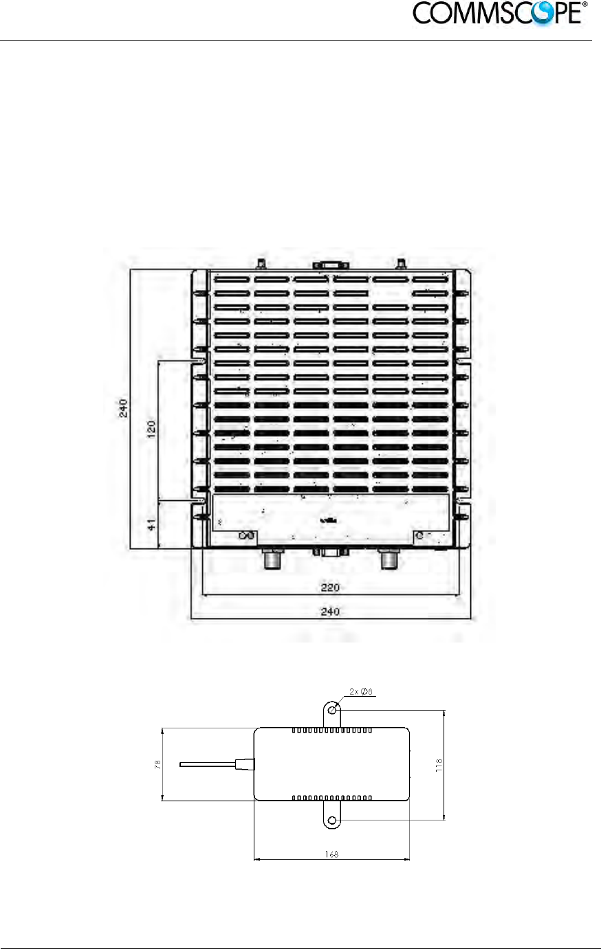
User’s Manual for ION-B Systems
ION-B User Manual (MN024-
15)_n_20150730.docx Page 121
5.4.2. TFBx Case B Installation
The case B TFBx can be mounted to wall or other flat surfaces.
The TFBx kit includes:
1. a Booster TFBx
2. an external power supply adapter
3. a power supply plug
4. a serial cable (if applicable)
Figure 5-6 Case B layout with dimensions
Figure 5-7 Layout of the power adapter with dimensions
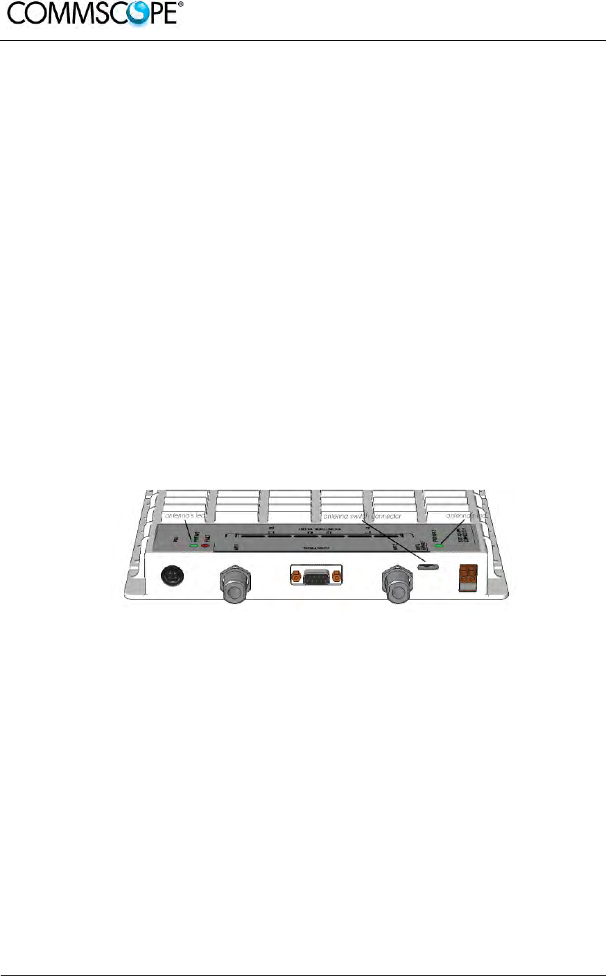
User’s Manual for ION-B Systems
Page 122 ION-B User Manual (MN024-15)_n_20150730.docx
Once you have chosen a location for the booster, please follow these instructions:
1. In order to install the M4 dowels (not included) which hold up the TFBx
booster, drill four holes into the wall according to the layout shown in Figure
5-6 Case B layout with dimensions
2. Mount the TFBx to the wall by firmly fastening the screws into the dowels.
3. In order to install the M4 screw dowels (not included) which hold up the
power supply external adapter, drill two holes into the wall according to the
layout of the power supply, shown in Figure 5-7 Layout of the power
adapter with dimensions.
4. Mount the external power supply to the wall by firmly fastening the screws.
5. Connect the RF auxiliary ports of the booster to the relevant ports of the
Remote Unit
6. If applicable connect the antenna ports of the Remote Unit to the boosters
inputs to have internal combination and common antenna’s output
7. If applicable connect the RS232 port of the Remote Unit to the one of the
booster through the RS232 cable provided.
8. Connect the external adapter to the TFBx Booster with the proper cable.
9. Use the dip-switch to choose between the one or two antenna port
configuration for the booster
10. If needed cable the relay alarm outputs of the booster with the relay alarm
inputs of the Remote Unit to have the booster supervised through the
Remote Unit itself.
11. Once the installation is finished, please follow the 5.7 section in order to
carry out a proper system start up.
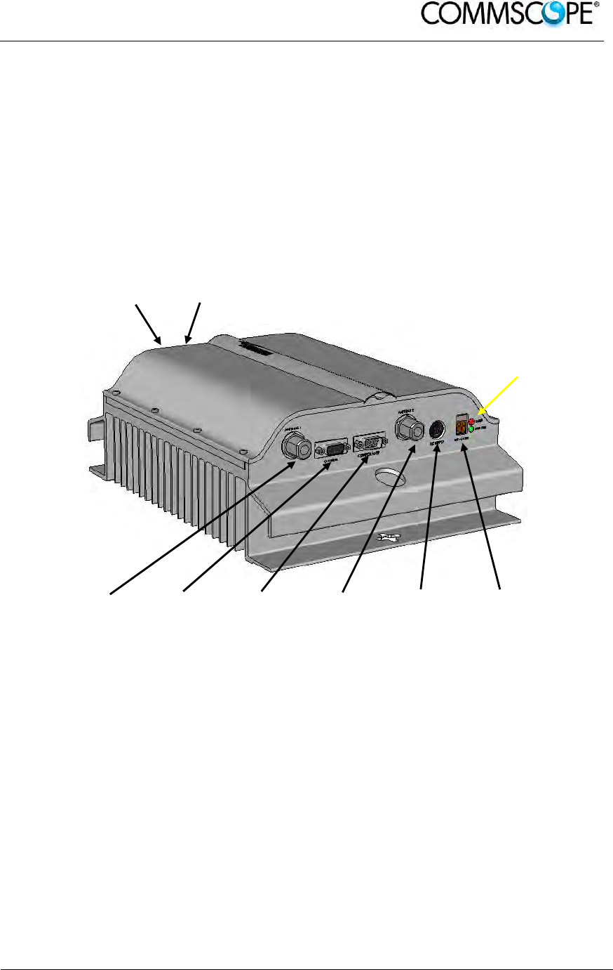
User’s Manual for ION-B Systems
ION-B User Manual (MN024-
15)_n_20150730.docx Page 123
5.5. CASE R2 BOOSTER
5.5.1. Specifications
Dimensions: 122.5 x 330 x 250 mm
(4.8 x 13 x 9.8 inches)
Weight: Please refer to the booster dedicated bulletin in order get updated
data regarding the weight of a specific Case R2 booster
RF
Auxiliary
Port UL
RF
Auxiliary
Port UL
RF
antenna
port 1
RS232 for
laptop
connection
RS232 to be
connected to
the RU
RF
antenna
port 2
Power
supply
connector
External
alarm
connection
RF ports
• 2 RF antenna ports, transmitting/receiving signals to/from distributed
antennas. RF antenna ports are duplexed N-female connectors. These RF
ports can be connected to the antennas either directly (i.e. through RF jumper
cables) or through splitters, thus allowing more antennas to be fed. Unused
RF ports have to be terminated with a 50 Ω load.
• 1 RF auxiliary input and 1 RF auxiliary output (designed to receive and
transmit signals to the Remote Units). Auxiliary input and output ports are
SMA-female connectors.
LED alerts
Green = power ON
Red = major alarm
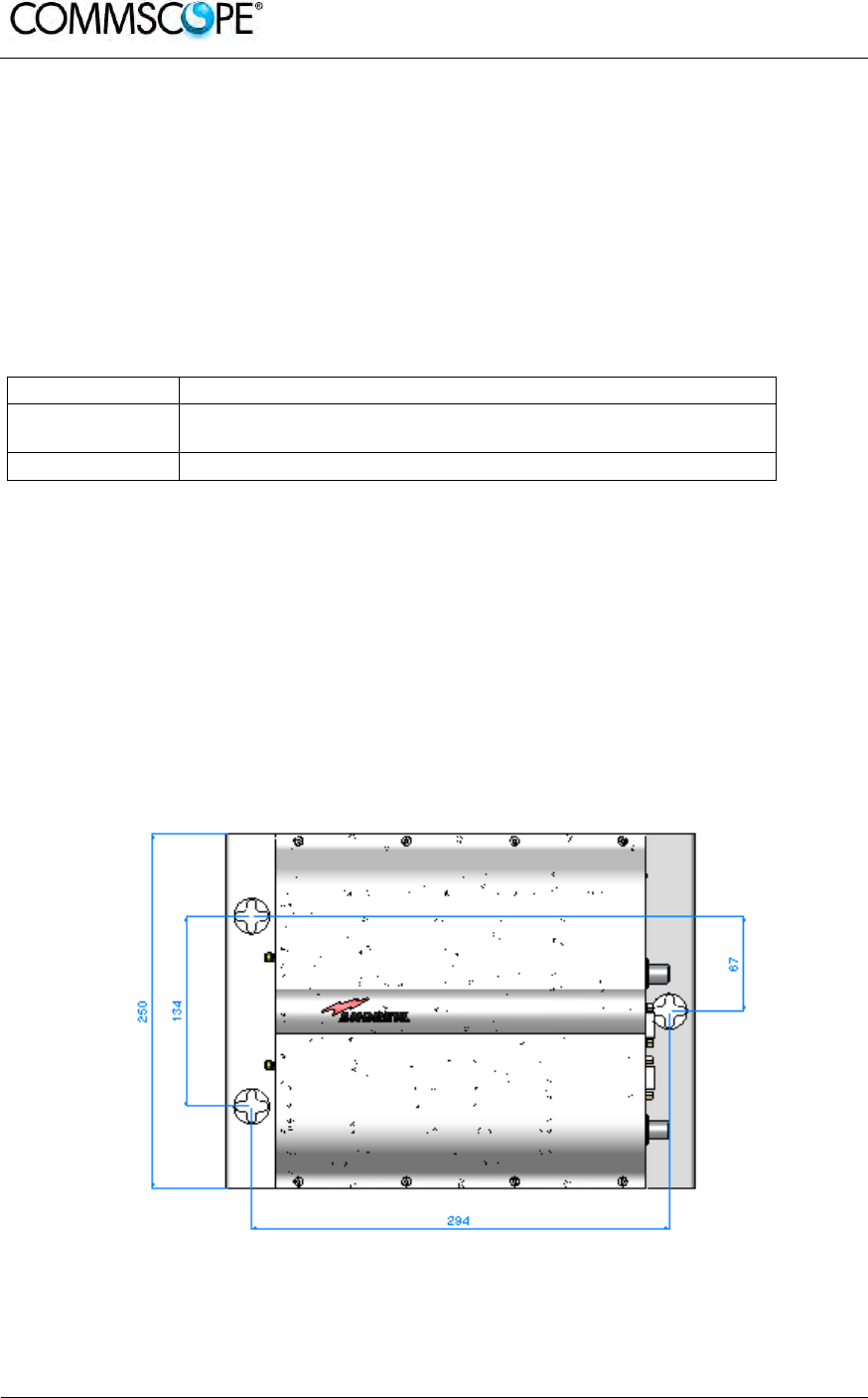
User’s Manual for ION-B Systems
Page 124 ION-B User Manual (MN024-15)_n_20150730.docx
Alarm Relay Outputs
The TFBx is provided with two alarm relay outputs which can be cabled and
connected to the Remote Unit’s alarm relay inputs. This way, the alarm information of
the booster pass to the Remote Unit itself and are signalled through the red LED of
the TFAx and displayed in the supervision system.
Visual Alarms
Two control LEDs are provided on the TFBx case R2 front side. The green LED
indicates the power supply status, while the red LED indicates any major booster
failures (please refer to the respective troubleshooting section).
LED colour Meaning
Red Low optical power at DL input and/or RF amplifier failure
Green Power supply OK
table 5-3 Status and Alarm LED Indication
5.5.2. TFBx Case R2 Installation
The Case R2 Booster can be mounted to walls or other flat surfaces.
The TFBx kit includes:
1. a Booster TFBx
2. an external power supply adapter
3. a power supply plug
4. a serial cable
Figure 5-8 Case R2 layout with dimensions

User’s Manual for ION-B Systems
ION-B User Manual (MN024-
15)_n_20150730.docx Page 125
Figure 5-9 Layout of power adapter with dimensions
Once you have chosen a location for the booster, please follow these instructions:
1. In order to install the M6 dowels (not included) which hold up the TFBx
booster and the power supply drill four holes into the wall according to the
layout shown in Figure 5-8 Case R2 layout with dimensions and Figure 5-9
Layout of power adapter with dimensions.
2. Insert the M6 dowels into the holes and fasten the power supply to the wall.
If you planned to use a common screw anchor to support both the booster
and the external power supply, take care not to screw this dowels till you
fastened the booster.
3. Fasten the booster to the wall and tighten the 4 dowels.
4. Connect the RF auxiliary ports of the booster to the relevant ports of the
Remote Unit
5. Connect the RS232 port of the Remote Unit to the one of the booster
through the RS232 cable provided.
6. Connect the external adapter to the TFBx Booster with the proper cable.
7. If needed cable the relay alarm outputs of the booster with the relay alarm
inputs of the Remote Unit to have the booster supervised through the
Remote Unit itself.
8. Once the installation is finished, please follow the 5.7 section in order to
carry out a proper system start up.
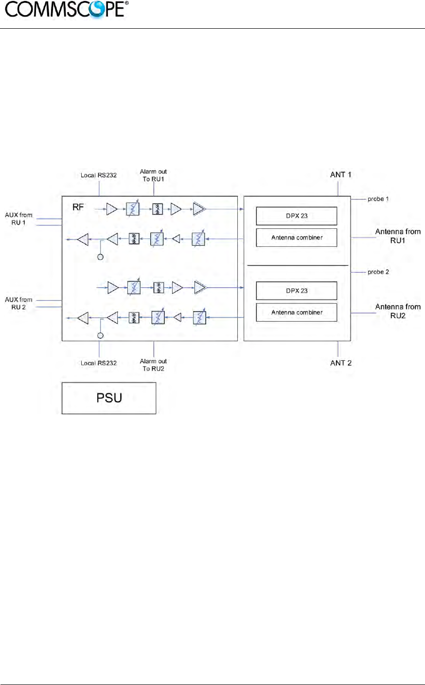
User’s Manual for ION-B Systems
Page 126 ION-B User Manual (MN024-15)_n_20150730.docx
5.6. CASE U BOOSTER
5.6.1. Specifications
Dimensions: 514 x 480 x 205 mm
(20.2 x 18.9 x 8 inches)
Weight: Please refer to the booster dedicated bulletin in order get updated
data regarding the weight of a specific Case U booster
figure 5-10 Block diagram Case U booster
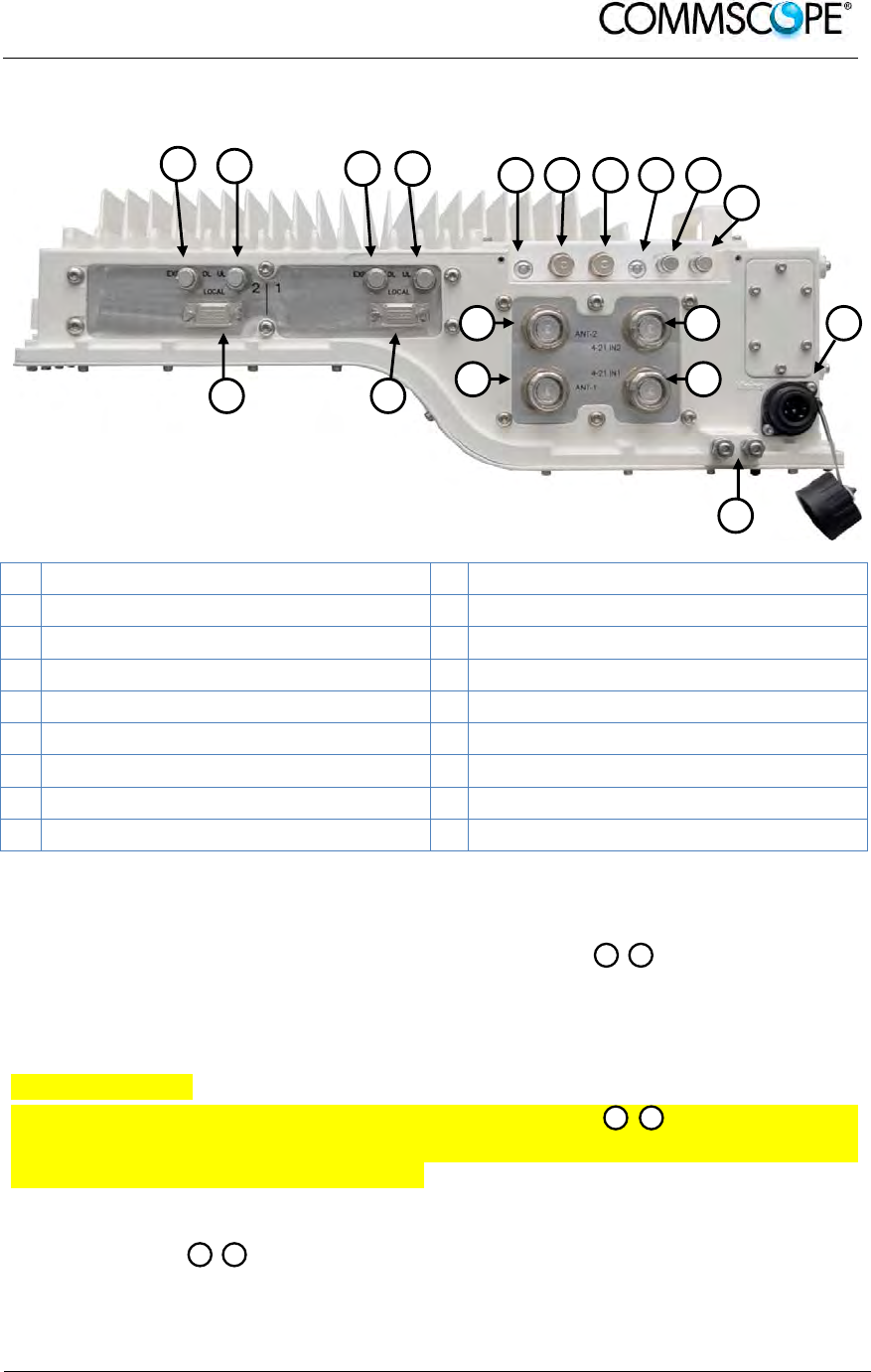
User’s Manual for ION-B Systems
ION-B User Manual (MN024-
15)_n_20150730.docx Page 127
The RF, mains power, alarm, power control, and expansion ports are located on the
bottom of the booster.
A Expansion DL port path 2 J Probe path 1
B Expansion UL port path 2 K Mains power connector
C Expansion DL port path 1 L Grounding (earthing) bolts
D Expansion UL port path 1 M RF antenna port 4-21 IN path 1
E Status LED path 2 N RF antenna port 4-21 IN path 2
F Alarm connector 2 O RF antenna port OUT path 2
G Alarm connector 1 P RF antenna port OUT path 1
H Status LED path 1 Q Local Port RS-232 path 1
I Probe path 2 R Local Port RS-232 path 2
figure 5-11 Booster connectors and Status LEDs
Antenna Ports OUT
The booster has two duplex 4.3-10 female antenna ports for transmitting and
receiving signals to and from distributed antennas. These RF ports can be connected
directly to antennas (i.e. using RF jumper cables) or through splitters, allowing
additional antennas to be fed by the booster.
Antenna Ports IN
The booster has two duplex 4.3-10 female antenna ports for connecting the
antenna OUT ports of two TFAx Remote Units. The signals are combined and fed to
the RF antenna OUT ports of the booster.
Status LEDs
The status LEDs provide a visual warning of an alarm condition. The color of
the LED indicates the severity of the alarm.
H E
NM
PO
A B C D E F G H I
J
N
M P
O
Q
K
R
L
User’s Manual for ION-B Systems
Page 128 ION-B User Manual (MN024-15)_n_20150730.docx
Expansion Ports
The Expansion UL and Expansion DL ports are QMA female connectors
that are used to connect to two RUs to receive the additional bands. These ports
must be terminated if not used.
Mains Connector
The booster receives its power through the Mains connector . The type of
connector is dependent on the booster model. A 4-pin Amphenol connector is used
for AC models and standard DC models. A 7-pin Amphenol connector is used for DC
models powered by a dual cable supply.
Alarm Connector
The booster has two summary alarm relay outputs that can be used to connect to the
corresponding TFAx external alarm inputs and monitor the status of the booster. The
alarm connectors are 5-pin Binder connector.
Local Port RS-232
The RS-232 ports are standard DB-9 female connectors. They are local
interfaces to the booster.
Probe Port
The probe ports are QMA measurement probes that allow the measurement of
the antenna outputs without disconnecting the antennas. The coupling is as follows:
Port Coupling dB typ.
2300 MHz 41.5
J I
Q
R
G F
K
C
A
D B
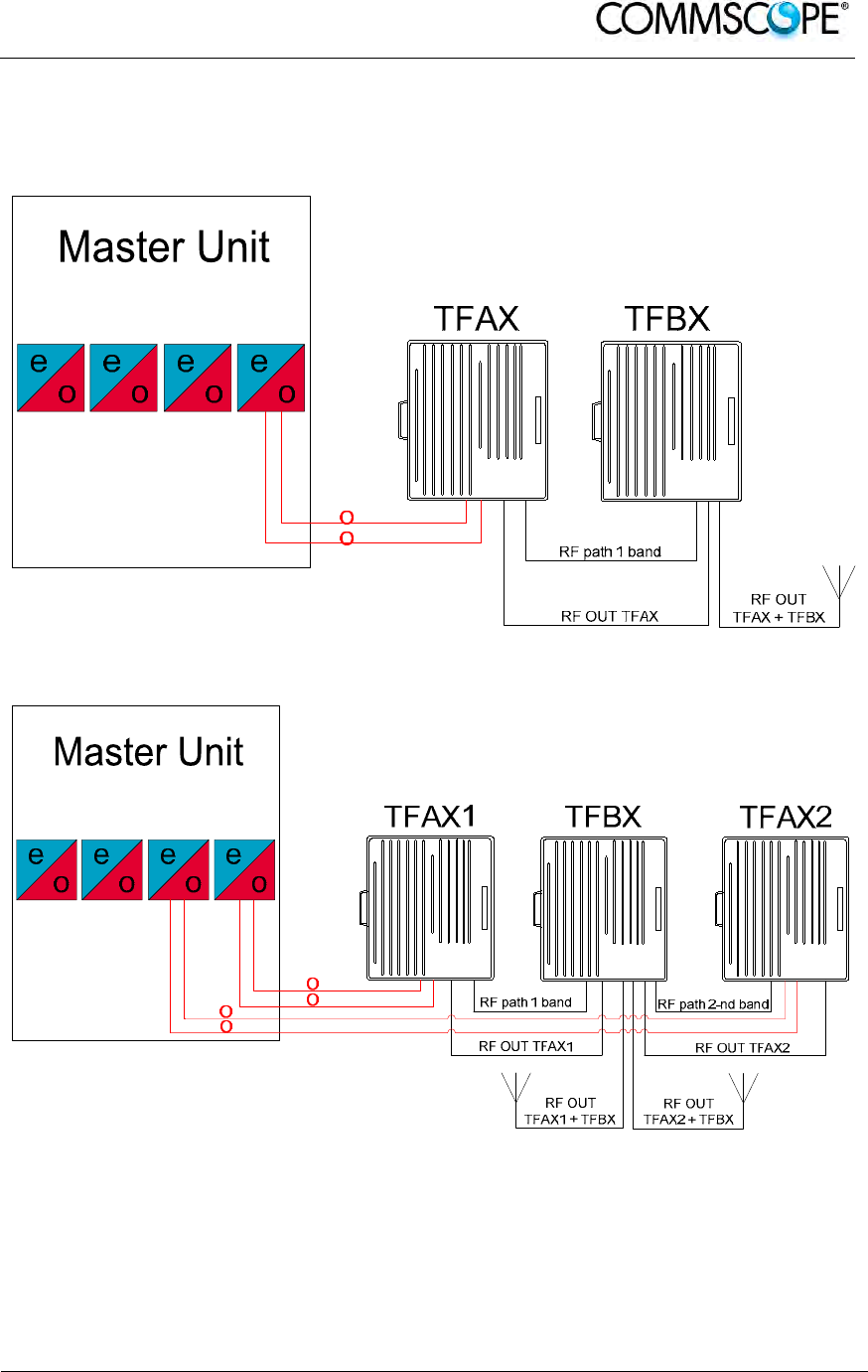
User’s Manual for ION-B Systems
ION-B User Manual (MN024-
15)_n_20150730.docx Page 129
5.6.3. TFBx Case U applications
The TFBx with integrated antenna port combiner together with ION-B TFAx RU
allows for further options.
figure 5-12 One RU one booster one antenna
figure 5-13 Two RUs one booster two antennas

User’s Manual for ION-B Systems
Page 130 ION-B User Manual (MN024-15)_n_20150730.docx
5.6.4. TFBx Case U Installation
Before the installation of the TFBx Case U booster read and observe chapters 4.10.2
and 4.10.3.
The mechanical installation of the TFBx Case U booster is identical to the installation
of the TFAx Case U. For mounting the booster to a wall or pole see chapter 4.10.5.
The electrical installation of the TFBx Case U booster is almost identical to the
installation of the TFAx Case U. For the electrical connection see chapter 4.10.7.
The differences in electrical installation are:
the TFBx has got no optical connection, no fiber has to be connected to the
booster
the TFBx has got two alarm connectors for alarm connection to the two
TFAxs, one for each TFAx
the TFBx has got two antenna OUT ports for the connection of two antennas,
one for each amplified band
the TFBx has got two antenna IN ports for combining the RF signals from the
TFAxs and the TFBx to the OUT ports of the TFBx, one for each TFAx; the
cables (4.3-10 to N, 1.5 m) are part of the delivery
the TFBx antenna port connectors are 4.3-10 female, not N female
5.6.5. TFBx Case U Power Supply Replacement
The replacement of the power supply unit is identical to the replacement of the power
supply of the TFAx Case U. For replacing the power supply of an TFBx Case U see
chapter 4.10.8.3.

User’s Manual for ION-B Systems
ION-B User Manual (MN024-
15)_n_20150730.docx Page 131
5.7. TFBX BOOSTER START-UP
Before the TFBx booster is switched on, make sure that:
• the modules hosted in the Master Unit have been connected to each other with
RF jumpers, according to the system design
• each TFLN Master optical TRX has been connected to its RU
• each booster has been connected to its Remote Unit (both RF and RS232 if
applicable)
• each booster and Remote Unit has been connected to its coverage antennas
For a correct system start-up, all the RUs and boosters have to be switched on prior
to the Master Unit.
Once the TFBx has been switched on, its behaviour can be summarized as per the
following indicators:
1. When the booster is turned on, both LEDs turn on for a couple of seconds.
2. After that, the unit’s green LED remains on (thus indicating proper power
supply), while the red LED switches off.
3. If the booster is connected to the Remote Unit through the RS232 port, once the
booster is switched on the red led of the Remote Unit blinks for a couple of
seconds until the Remote Units gets all the information from the booster about
possible band which needs shut down.

User’s Manual for ION-B Systems
Page 132 ION-B User Manual (MN024-15)_n_20150730.docx
5.8. TROUBLESHOOTING
5.8.1. List of All Alarms
Errors are indicated by LEDs on the TFBx front panel, as well as by LMT or the
Supervision System (running on the remote supervision unit) supposed that the relay
alarms have been cabled.
The booster is not communicating the whole list of alarms, only the Remote Unit can
alert (with the external alarm information) trough the LMT and the Supervision
System that the booster has a wrong behaviour.
The following table shows a brief description of the possible alarms related to a
booster, with reference to the corresponding alerted LEDs and to the actions to be
carried out in case of a fault. Boosters can have a sub-set of the below alarms.
ALARM CODE ALARM DESCRIPTION ACTIVE
LED
ACTION
RECOMMENDED
RELÉ PRIORITY
LEVEL (subrack)
DL ALC overpower Power has increased the ALC range RED Check the RF power MAJOR
Synchronism Fault Synchronism has been loosen RED
Check master unit
and the fiber. If it
works properly,
replace the unit
MAJOR
PLL alarm PLL is not locked to the frequency RED Return the unit MAJOR
Power supply alarm UPS HW failure or malfunction. RED
Check external PSU.
If it works properly,
replace the unit
MAJOR
table 5-4 Booster’s Alarm
The troubleshooting procedures are described in the following chapter.
5.8.2. Quick Troubleshooting
If the red LED is ON, please follow these steps:
1. Check the master unit to see if synchronism (if applicable) and RF power works
properly
2. If it does not clear the failure, return the unit
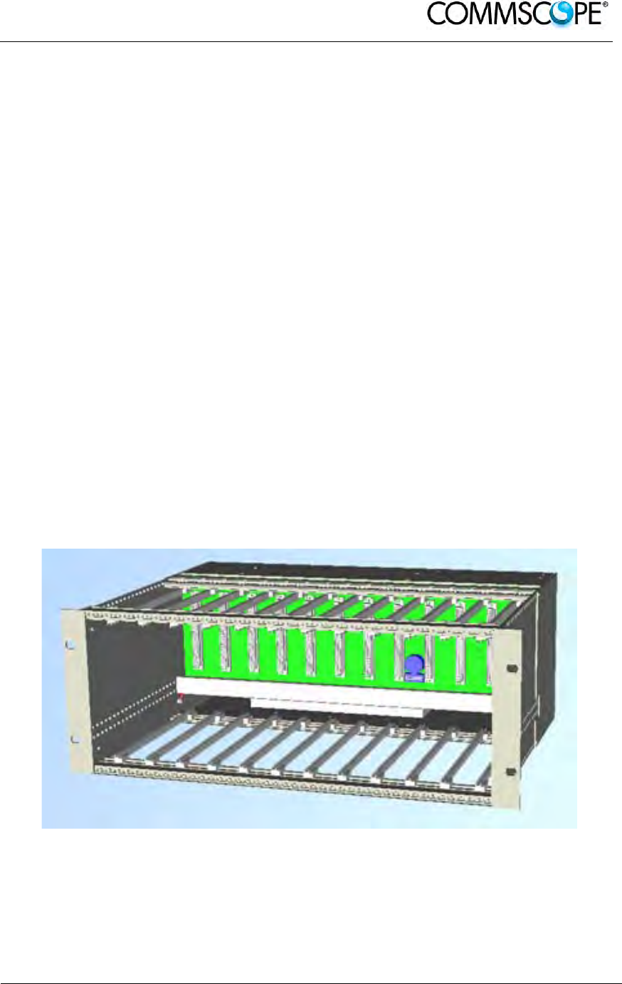
User’s Manual for ION-B Systems
ION-B User Manual (MN024-
15)_n_20150730.docx Page 133
6. RACK-BASED MASTER UNIT
6.1. TPRNX4 SUBRACK
6.1.1. Major TPRN Features
The TPRNx4 is a 19” subrack where all the ION-B plug-in modules can be inserted.
ION-B equipment provides a wide variety of these subrack models differentiated
according to power supply. Each one is provided with:
• 12 free slots, each with Height=4HE, Width=7TE
• Power supply 220 Vac or -48 Vdc
• Locally or remotely connectable through:
a. RS232 serial port
b. RS485 two-wire bus
c. sub-D 15 pin male-connector
• Internal microcontroller for I2CBUS alarm collection
• Manual reset button, able to re-initialize both the inserted modules and the
TPRN microcontroller
• Manual stand-by button, able to re-initialize the inserted modules, while
keeping the TPRN microcontroller working.
Figure 6-1 TPRN subrack
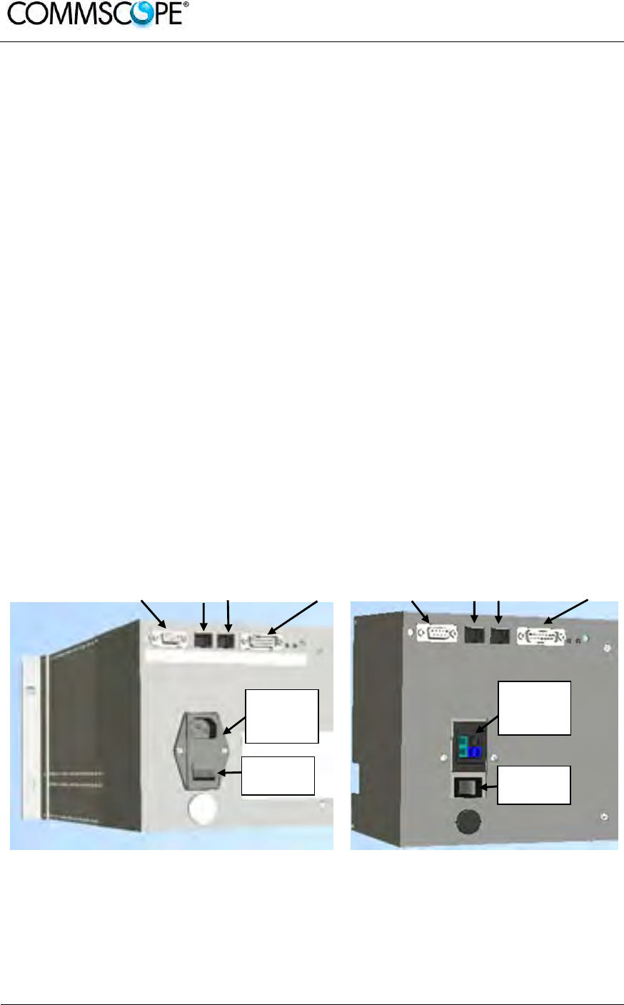
User’s Manual for ION-B Systems
Page 134 ION-B User Manual (MN024-15)_n_20150730.docx
6.1.2. TPRN Models
All of the available TPRN subracks are described briefly on the following pages:
6.1.2.1. Passive subrack (TPRN04)
TPRN04 is a passive subrack. It cannot supply power to any inserted module, and
therefore is designed to host passive modules only. It can be useful in a multi-
subrack system, in case the customer decides to put all the active modules in an
active subrack, to be chosen among the following:
6.1.2.2. 220 Vac powered subracks (TPRN14 / TPRN24)
TPRN14 is an active subrack designed to be fed through 220 Vac universal mains.
Both the connector for the 220 Vac power supply and the communication ports are
placed on the rear of subrack. The 220 Vac power supply is not redundant (ie, no
spare adapter is provided).
TPRN24 is an active subrack designed to be fed through 220 Vac universal mains.
Both the connector for the 220 Vac power supply and the communication ports are
placed on the rear of subrack, and the 220 Vac power supply is redundant: i.e., a
spare adapter guarantees the correct system operations even if the main 220Vac
adapter has a breakdown.
6.1.2.3. -48Vdc powered subrack (TPRN34)
TPRN34 is an active subrack designed to be fed through a –48 Vdc negative supply.
Both the connector for the -48Vdc power supply and the communication ports are
placed on the rear of the subrack.
RS232 port RS485 ports
sub-D 15
connector RS232 port RS485 ports sub-D 15
connector
(a) (b)
Figure 6-2 Rear view of the TPRN subrack with 220Vac power supply (a) and with -
48Vdc power supply (b)
Power
supply
220Vac
Power
supply
48Vdc
Switch
On/Off
Switch
On/Off
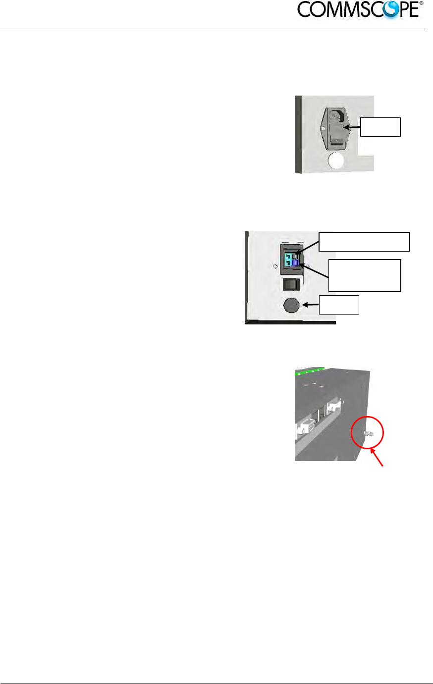
User’s Manual for ION-B Systems
ION-B User Manual (MN024-
15)_n_20150730.docx Page 135
6.1.3. TPRN Power Supply
All the TPRN models refer to one of the following power supplies:
Universal mains
(85 to 265Vac, 50/60Hz).
This connector is mounted on the TPRN back
panel, both for the redundant version and the
simple one. A ground terminal and a couple of
fuses are also included. Fuses must be
replaced in case of failure (if it happens, the
failure is detected by the Supervision System).
Figure 6-3 85 to 265Vac inlet
-48 Vdc
(-72 to -36 Vdc)
This connector is mounted on the back panel of
the TPRN.
A fuse is provided underneath the -48 Vdc
connector, and must be replaced in case of
failure (if it happens, the failure is detected by
the Supervision System).
Figure 6-4 -48Vdc inlet
Whichever power supply is chosen (85 to 265
Vac or -72 to -36 Vdc) an additional external
ground connector is provided on the rear of the
TPRN.
The external power supply (220Vac or -48Vdc)
is converted to a +12Vdc voltage, feeding the
active modules inserted into the TPRN.
Figure 6-5 Ground connector
Fuse
Fuse
Blue terminal:
-72-36 Vdc
Blue terminal: 0 V
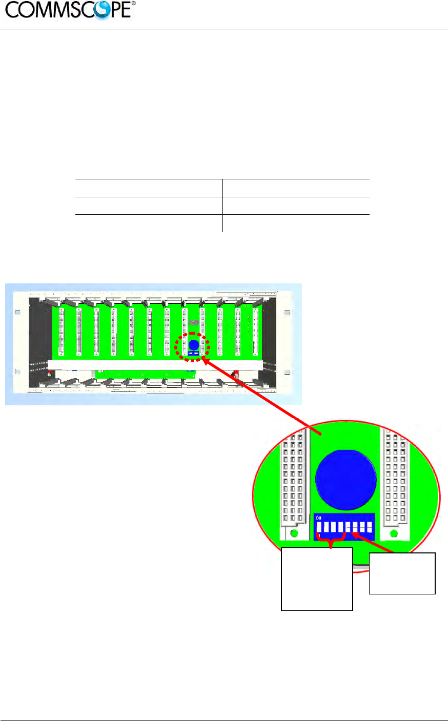
User’s Manual for ION-B Systems
Page 136 ION-B User Manual (MN024-15)_n_20150730.docx
6.1.4. TPRN Ports
The TPRN subrack is provided with a set of I/0 ports which allows the connection to
any external device.
6.1.4.1. RS232 serial port
The RS232 serial port can be used to connect the TPRN subrack to the remote
supervision unit or to a laptop running LMT software. Please note that a standard
RS232 cable is needed.
Baud rate (bps) Dip-switch 5
9600 OFF
19200 ON
table 6-1 Setting the RS232 baud rate through the dip-switch 5
Figure 6-6 Dip-switches on the TPRN backplane
RS485
addressing
dip-switches
(Dip-switches
1 to 4)
Baud-rate
dip-switch
(Dip-switch 5)

User’s Manual for ION-B Systems
ION-B User Manual (MN024-
15)_n_20150730.docx Page 137
The connection baud rate can be set to 9600bps or 19200bps, by properly setting the
dip-switch 5 standing on the interior TPRN backplane (Figure 6-6 Dip-switches on the
TPRN backplane). The baud rate setting through dip-switch 5 is shown in table 6-1
Setting the RS232 baud rate through the dip-switch 5.
Whichever baud rate you choose through dip-switch 5, remember that:
• the same RS232 connection speed must be set up on the remote supervision
unit
• the baud rate which is selected through the dip-switch 5 sets the connection
speed for both the RS232 port and the RS485 port as the TPRN uses both
ports with the same rate.
6.1.4.2. RS485 port
The RS485 port consists of two RJ45 connectors, which can both work as input or
output ports towards a RS485 bus.
This RS485 bus has to be used in order to connect a multi subrack system to the
remote supervision unit. In this case:
• the TPRN subracks have to be connected to one another via RS485 bus in a
daisy chain;
• In order to monitor the whole system, the remote supervision unit has to be
connected to one of the TPRN subracks through RS232 port.
Before connecting the TPRN subracks belonging to a multi-subrack system,
remember to assign an exclusive binary address to each one. This is essential in
order to allow the Supervision System recognize the different master units without
any conflicts.
The binary address assignment can be done through dip-switches 1,2,3,4, which are
on the interior TPRN backplane (see Figure 6-6 Dip-switches on the TPRN
backplane). A list of correspondences between the addresses and the dip-switches is
provided in table 6-2 Dip-switches address settings: simply note that dip-switch 1 is
the least significant binary digit, while dip-switch 4 is the most significant one.
The baud rate of the RS485 ports is the same as the RS232 port as per the dip-
switch 5 setting.
Whichever baud rate you choose, remember that:
• the same RS485 connection speed has to be set up on for the entire
connected device (TPRN subracks or TSUN remote supervision unit);
• the baud-rate which is selected through the dip-switch 5 sets the connection
speed for both the RS485 port and the RS232 port.
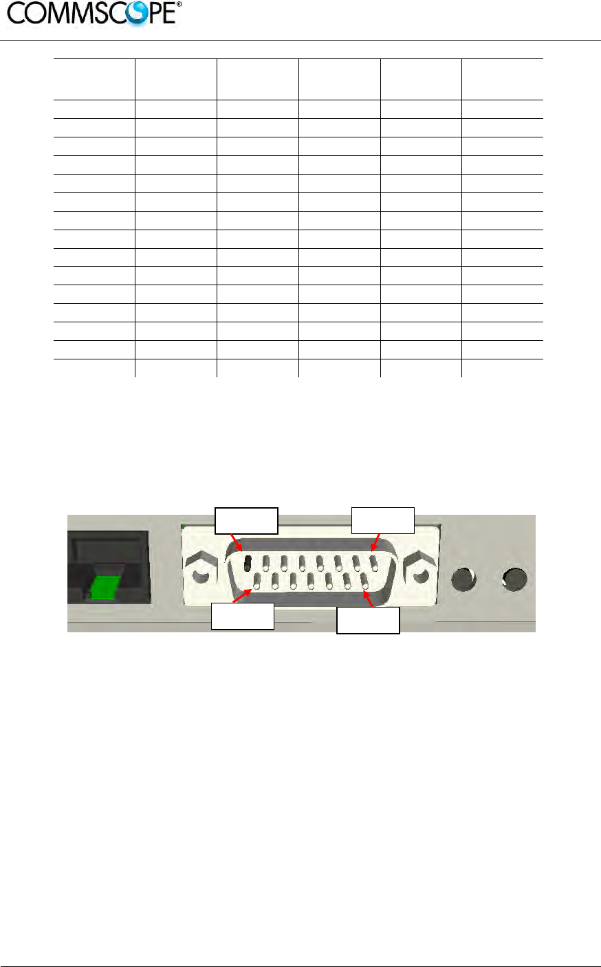
User’s Manual for ION-B Systems
Page 138 ION-B User Manual (MN024-15)_n_20150730.docx
Address
(Dec) Address
(Bin) Dip-
switch 1 Dip-
switch 2 Dip-
switch 3 Dip-
switch 4
1 1 ON OFF OFF OFF
2 10 OFF ON OFF OFF
3 11 ON ON OFF OFF
4 100 OFF OFF ON OFF
5 101 ON OFF ON OFF
6 110 OFF ON ON OFF
7 111 ON ON ON OFF
8 1000 OFF OFF OFF ON
9 1001 ON OFF OFF ON
10 1010 OFF ON OFF ON
11 1011 ON ON OFF ON
12 1100 OFF OFF ON ON
13 1101 ON OFF ON ON
14 1110 OFF ON ON ON
Reserved 1111 ON ON ON ON
table 6-2 Dip-switches address settings
6.1.4.3. Sub-D 15 poles male connector
The TPRN subrack provides sub-D 15 poles male connector, shown in Figure 6-7
Sub-D 15 poles male connector.
Figure 6-7 Sub-D 15 poles male connector
The pins are numbered from left to right, and from top to bottom (refer to Figure 6-7
Sub-D 15 poles male connector).
A more detailed description of the meaning and functionality of each pin is reported in
table 6-3 Functional description of pins provided by sub-D male connector.
This connector provides:
• 4 opto-isolated input ports which can be used to reveal any failure condition on
external equipment. The default status of these input ports can be defined
through the Supervision System. After that, any change from default status will
be revealed as a failure signal.
• a summary of major and minor alarms related to failures detected not only on
the TPRN subrack, but also on any active modules hosted by the TPRN itself.
PIN 1 PIN 8
PIN 9 PIN 15

User’s Manual for ION-B Systems
ION-B User Manual (MN024-
15)_n_20150730.docx Page 139
• 2 relay output ports, which be can used to drive any external device connected
to subD-15 pins adapter. By using the Supervision System, each of these
output ports be can set up in “open” or “close” modes.
PIN Name Meaning
1 Ground It is a ground terminal for digital inputs, i.e. for pin 2, 3, 9,
10.
2 Digital input
n.1 (SW
assignable)
This port can be used to monitor external equipment
status. Once a default working status has been assigned
(through the Supervision System) to this input port, any
change is detected as a failure signal.
3 Digital input
n.2 (SW
assignable)
This port can be used to monitor external equipment
status. Once a default working status has been assigned
(through the Supervision System) to this input port, any
change is detected as a failure signal.
4 Disconnected
pin No meaning
5, 6 Summary of
major alarms These pins present an open circuit if a major alarm is
active on the TPRN subrack or on any module hosted in it.
7, 8 Summary of
minor alarms These pins present an open circuit if a minor alarm is
active on the TPRN subrack or on any module hosted in it.
9 Digital input
n.3 (SW
assignable)
This port can be used to monitor external equipment
status. Once a default working status has been assigned
(through the Supervision System) to this input port, any
change is detected as a failu
r
e signal.
10 Digital input
n.4 (SW
assignable)
This port can be used to monitor external equipment
status. Once a default working status has been assigned
(through the Supervision System) to this input port, any
change is detected as a failure signal.
11 Disconnected
pin No meaning
12,
13
Digital output
n.1 (SW
assignable)
These pins are terminals of an output port (output relay 1),
which can be driven through the Supervision System. The
output port can be set to “open” or “close” condition. These
2 statuses can be used to pilot any external device
connected to subD-15 connector.
14,
15
Digital output
n.2 (SW
assignable)
These pins are terminals of an output port (output relay 2),
which can be driven through the Supervision System. The
output port can be set to “open” or “close” condition. These
2 statuses can be used to pilot any external device
connected to subD-15 connector.
table 6-3 Functional description of pins provided by sub-D male connector
Note: The TPRN subrack uses I2Cbus standard protocol to collect status
and alarm information from hosted modules. Thanks to that, the
alarm summaries (provided through pins 5-6 and 7-8) report major
and minor failures related not only to the TPRN subrack but also to
any hosted modules.

User’s Manual for ION-B Systems
Page 140 ION-B User Manual (MN024-15)_n_20150730.docx
6.1.5. TPRN Alarms
A full description of all TPRN alarms is provided by the Supervision System; The
following table provides a brief description of the TPRN alarms, as they are reported
by the LMT software.
TSUN Alarm
Codedescription Alarm
Description Active
LED Supervision
Priority Level Action Reco-
mended RELÉ
Priority
Redundant supply
active(only for
redundant power
supply versions)
Backup power
supply activated YEL-
LOW MAJOR Return the
unit MINOR
Power Supply
alarm
There is a
degradation on
the power supply
provided to the
boards
RED MAJOR
Return the
unit MAJOR
I2CBUS bus error Internal I2CBUS
communication
malfunction
YEL-
LOW CRITICAL
Check if the
fault is on the
unit (see
Supervision
System). If
not, return the
unit
MINOR
Temperature alarm Over-
temperature
alarm
YEL-
LOW MINOR
Check
ventilation
and
environment
MINOR
Aux input alarm nr0
The device
connected to the
input alarm port
0 caused an
alarm condition
RED CRITICAL
Check the
status of the
connected
device
-
Aux input alarm nr1
The device
connected to the
input alarm port
1 caused an
alarm condition
RED MAJOR
Check the
status of the
connected
device
-
Aux input alarm nr2
The device
connected to the
input alarm port
2 caused an
alarm condition
RED MINOR
Check the
status of the
connected
device
-
Aux input alarm nr3
The device
connected to the
input alarm port
3 caused an
alarm condition
RED WARNING
Check the
status of the
connected
device
-
table 6-4 Description of the alarms of the TPRN subrack

User’s Manual for ION-B Systems
ION-B User Manual (MN024-
15)_n_20150730.docx Page 141
6.1.6. Warnings - recommended when designing or installing
6.1.6.1. Providing correct heat dissipation
For correct use of the TPRN subrack, it is important to verify that:
• the system is designed for no more than 8 TFLNs inside a TPRN subrack. This
guarantees proper heating dissipation for the system. In case you want to
install more than 8, it is important to provide the subrack with a proper
ventilation system;
• active and passive modules should be alternated as much as possible inside
the TPRN subrack avoiding too many active cards being inserted close
together;
• in case the system consists of more than one TPRN subrack, a minimum
distance of 1 HU has to be kept between nearby TPRN subracks to ensure
proper heat dissipation. The rack containing the TPRN subracks has to be
large enough to guarantee this correct distance between master units.
6.1.6.2. Minimizing equipment costs
In order to reduce the cost of ION-B equipment, a multi-subrack system should be
designed according to the following guidelines:
• a passive subrack (TPRN04) may be used to house only passive modules;
• an active subrack (TPRN14, TPRN24, TPRN34) may be used to sustain all the
active modules, and some of the passive ones (as stated above, it is advisable
to alternate active and passive cards in an active subrack).
6.1.6.3. Setting the dip-switches in a multi subrack system
If you are installing a multi-subrack system, remember to assign each subrack an
exclusive binary address, by properly setting dip-switches 1,2,3,4 on the interior
TPRN backplane (see Figure 6-6 Dip-switches on the TPRN backplane and table 6-2
Dip-switches address settings). Dip-switch 5 has to be set on each TPRN subrack in
order to fix the baud rate for the RS485 and RS232 ports. Connecting the TPRNs
through the RS485 port is necessary when supervising the whole multi subrack
system through the remote supervision unit (to be set at the same baud rate).

User’s Manual for ION-B Systems
Page 142 ION-B User Manual (MN024-15)_n_20150730.docx
6.1.7. TPRN Installation
The TPRN kit provides:
• 1 TPRN subrack
• suitable power cord (a)
• 1 standard RJ45 cable (b)
• 1 standard RS232 cable
(male-female), 2m (c)
• 1 CD Manual (d)
(a) suitable power cord (b) standard RJ-45
cable
(c) RS232 cable (d) 1 Cd rom, including
ION-B manuals
Figure 6-8 Some of the installation accessories
provided with the TPRN subrack
Firstly, insert the subrack into the
cabinet and apply 4 screws (not
provided) in order to fix it.
To ensure correct TPRN
installation, distance between
the front door of the rack and the
front side of the TPRN should be
at least 15cm, otherwise the RF
and optical cables could be
damaged when cabinet door is
closed.
Figure 6-9 Mounting holes of TPRN
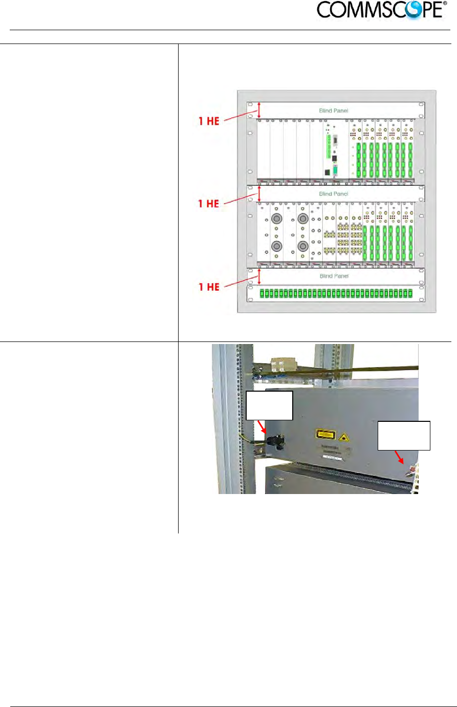
User’s Manual for ION-B Systems
ION-B User Manual (MN024-
15)_n_20150730.docx Page 143
Leave at least 1 HU distance
between two subracks in order to
facilitate air circulation.
Leave at least a 1 HU free space
between the bottom or the top of
the cabinet and the TPRNs.
Intra-subrack distance must be at least 1 HU to
allow air circulation. 1-HU inter-subrack distances
can be properly filled through blind panels.
Figure 6-10 Intra-subrack distance
Connect the ground to the safety
ground terminal.
Then, connect the power supply
connector to the mains.
Figure 6-11 Power supply and ground terminals on
the rear side of the TPRN subrack
Power
su
pp
l
y
Ground
terminal

User’s Manual for ION-B Systems
Page 144 ION-B User Manual (MN024-15)_n_20150730.docx
6.1.8. TPRN Start-up
Before switching on the TPRN subrack, make sure that:
• all necessary modules have been inserted
• the modules have been connected to each other by RF jumpers, according to
what has been planned during the system design
• each TFLN contained in the Master Unit has been connected to its TFAx
Remote Units
• each TFAx Remote Unit has been connected to its coverage antennas
• the remote supervision unit (if present) has been connected or housed to the
Master Unit
• different subracks have been connected to each other via bus RS485 and
each of them has different addresses
• the rack housing the TPRN is large enough to leave a minimum distance of 1
HU between contiguous TPRN subracks
Remember that TFAx Remote Units have to be switched on before the relevant
Master Unit.
Once the TPRN subrack has been switched on, the system behaviour can be
summarized by the following steps:
• About 10sec after the TPRN subrack has been switched on, all TFLN modules
housed in the TPRN itself begin a “discovery” phase in order to identify and
collect status of the connected TFAx Remote Units. While the discovery phase
is working (max. 4min. depending on the system complexity) each of the TFLN
general alarms (i.e., LED “ ”) blink, whereas the other TFLN LEDs go on
showing the detected status. Do not connect/disconnect any cable or piece of
equipment until all TFLN modules have finished the discovery phase. This may
result in failing to identify the TFAx. Regardless, during the discovery phase,
the entire system continues to work correctly as the discovery process aims to
collect information about the TFAx but without affecting basic system
functionalities.
• Once the discovery has finished, the general alarms (i.e. the LED “ ”) on
each TFLN panel stop blinking and switch OFF (provided that the TFLN
master optical TRX is not affected by a general failure).

User’s Manual for ION-B Systems
ION-B User Manual (MN024-
15)_n_20150730.docx Page 145
6.1.9. TPRN Troubleshooting
In case a TPRN subrack shows any problems, a more detailed status and alarm
description is able to be provided through the remote supervision unit.
A complete overview of TPRN alarms is provided in table 6-4 Description of the
alarms of the TPRN subrack.
A power supply degradation occurs in case the +12Vdc power falls below an in
factory set threshold level. In this case, the TPRN automatically switches to standby
mode so that no over-current is able to get through the circuitry of hosted modules,
thus preserving the system’s integrity. Once the power supply has been repaired, the
TPRN needs to be rebooted. In case the TPRN subrack is equipped with a redundant
power supply (TPRN24), a degradation of the +12 Vdc power results in an automatic
switching from main to spare converter. In case a redundant power supply is
degraded, the TPRN automatically turns to stand-by mode. Once the power supply
has been repaired, the TPRN needs to be rebooted.
A I2Cbus alarm occurs when the TPRN subrack is not able to communicate with one
or more of the hosted modules. Each TPRN slot is able to automatically detect the
presence of a module inside the slot. If the module is detected but the TPRN is not
able to communicate with it through the I2Cbus, an alarm is activated.
Note: At commissioning, remember to mask the unused slots through
LMT software (please refer to the relevant manual for more
information) to avoid triggering insignificant alarms.
Before carrying out any troubleshooting procedures, please check the LMT or
Supervision System manuals.
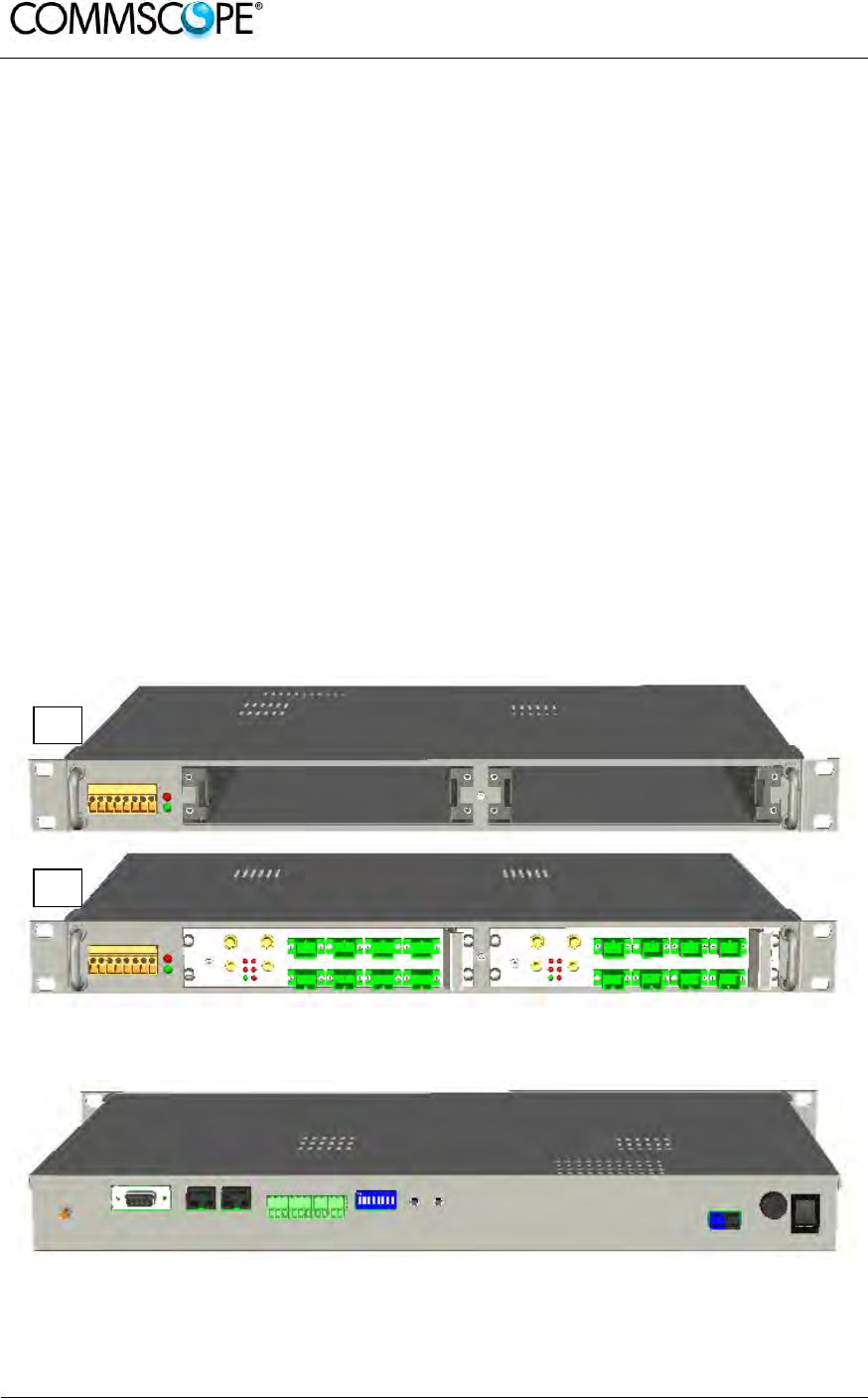
User’s Manual for ION-B Systems
Page 146 ION-B User Manual (MN024-15)_n_20150730.docx
6.2. FAST MINIRACK TPRF31
6.2.1. Major TPRF Features
The TPRF31 is a low-cost minirack (1HU x 19”) which can host 2 ION-B single-slot
cards, such as:
- 2 Master Optical TRX, thus being able to drive up to 8 ION-B Remote Units
- 1 Master Optical TRX (driving up to 4 ION-B Remote Units) and a proper ION-
B card, working as Point-of-Interface (POI) towards the BTS.
External splitting-combining modules are optionally available, thus providing a
complete solution for building simple and low-cost Distributed Antenna Systems.
Its installation-friendly brackets are suitable for both wall mounting and rack-
mounting, thus making the installation of the ION-B Fast MiniRack easy and
unobtrusive.
Thanks to its RS232 / RS485 bus, the TPRF31 Fast MiniRack can be fully integrated
with any additional ION-B MiniRacks or standard racks, and managed through the full
system supervision, using the ION-B standard supervision interface. Lastly, its
external dry contacts and auxiliary inputs allow the Fast MiniRack to collect
information about any external device, thus making it into a fully environment-
embedded device.
Figure 6-12 Front view of the TPRF31 Fast MiniRack, both with free slots (a) and
housing 2 TFLN master transceivers (b)
Figure 6-13 Rear view of the TPRF31 Fast MiniRack, powered -48 Vdc
a
b
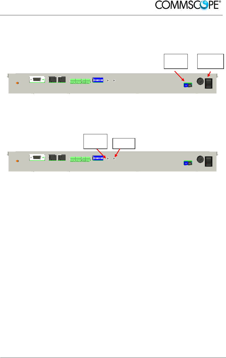
User’s Manual for ION-B Systems
ION-B User Manual (MN024-
15)_n_20150730.docx Page 147
6.2.2. On/Off Switch and Power Supply
The TPRF31 Fast MiniRack can be powered from -36 to -72 Vdc. A fuse is provided
underneath the -48 Vdc connector, and must be replaced in case of failure (when it
happens, the Supervision System will detect the failure).
Figure 6-14 Rear view of the TPRF31 Fast MiniRack: Power supply connectors and
On/Off switches
6.2.3. Reset and Store/Clear Buttons
Figure 6-15 Rear view of the TPRF31 Fast MiniRack: Reset and Store/Clear buttons
Reset
The Reset button, located on the TPRF31 rear side, performs a complete reset of the
Fast MiniRack, and is particularly useful when the MiniRack bus has become blocked
in any way. Compared to the “manual reset” which can be perfomed by switching off
and on the system through the On/Off switch, the Reset button is preferable because
it does not cause any interruption in feeding the TPRF31.
Store/Clear
The Store/Clear button, located on the TPRF31 rear side, carries out a complete
masking of the unused TPRF31 slots and of its TFLN ports. This operation should be
carried out during the initial system installation, after all of the TFLN units which are
hosted by the TPRF31 MiniRack have stopped blinking (i.e., after they have finished
the discovery phase: see the TFLN section of this User Manual for further
clarification).
The Store/Clear operation must also be carried out after any change affecting the
TPRF slot configuration and the used ports on the TFLN transceivers.
When switching on and off the system in any other circumstances, no Store/Clear
operation is normally required.
On/Off
switch
Power
-48Vdc
Reset
Store/
Clear
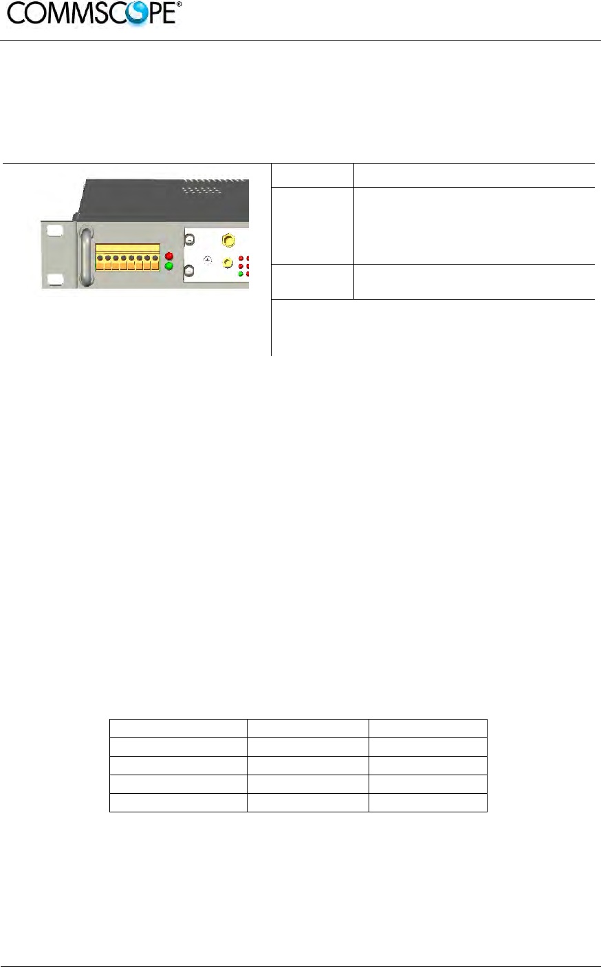
User’s Manual for ION-B Systems
Page 148 ION-B User Manual (MN024-15)_n_20150730.docx
6.2.4. Visual Alarms
The TPRF31 front panel is provided with 2 LEDs, showing status and alarm
information.
LED significances are provided in the following table.
LED colour Significance
Red
Failure on the TPRF31, on one of
the TFLN master transceivers, or
on one of the connected Remote
Units
Green Power supply status OK
Figure 6-16 TPRF31 visual alarms table 6-5 Meaning of the LEDs on the
TPRF31 front-side
Further information about alarm status is delivered by the ION-B Supervision
Systems.
6.2.5. TPRF31 Ports
The TPRF31 is provided with a series of ports which allow for the connection to any
external device. These different ports are described hereinafter.
6.2.5.1. RS232 Serial Port
The RS232 serial port can be used to connect the TPRF minirack to the remote
supervision unit or to a laptop running LMT software. Please note that a standard
RS232 cable is needed.
The connection baud rate can be set to 9600 bps, 19200 bps, 57600 bps, or 115200
bps by properly setting the dip-switches 6 and 7 on the rear panel of the TPRF31
backplane (Figure 6-17 Dip-switches on the TPRF31 backplane). The baud rate
setting using the dip-switches 6 and 7 is shown in table 6-6 Setting the RS232 baud-
rate through dip-switches 6 and 7.
Baud Rate [bps] Dip-switch 6 Dip-switch 7
9600 OFF OFF
19200 ON OFF
57600 OFF ON
115200 ON ON
table 6-6 Setting the RS232 baud-rate through dip-switches 6 and 7

User’s Manual for ION-B Systems
ION-B User Manual (MN024-
15)_n_20150730.docx Page 149
Figure 6-17 Dip-switches on the TPRF31 backplane
Whichever baud rate you choose by dip-switches 6 and 7, remember that:
• the same RS232 connection speed must be set up on the remote supervision
unit
• the baud rate which is selected by the dip-switches 6 and 7 set the connection
speed for both the RS232 port and the RS485 port as the TPRN uses both
ports with the same rate
6.2.5.2. RS485 Port
The RS485 port consists of two RJ45 connectors, which can both work as input or
output ports to and from a RS485 bus.
This RS485 bus has to be used in order to connect a multi subrack system to the
remote supervision unit. In this case:
• the TPRF miniracks have to be connected to one another via an RS485 bus in
a chain;
• in order to monitor the entire system, the remote supervision unit has to be
connected to one of the TPRF miniracks via an RS232 port.
Before connecting the TPRF miniracks belonging to a multi-subrack system,
remember to assign an exclusive binary address to each one. This is essential in
order to let the Supervision System recognize the different master units without any
conflict.
The binary address assignment can be done using dip-switches 1, 2, 3, 4, and 5,
which are located at the backplane of the TPRF (see Figure 6-17 Dip-switches on the
TPRF31 backplane). A list of the correspondences between the addresses and the
dip-switches is provided in table 6-7 Dip-switches address settings: simply note that
dip-switch 1 is the least significant binary digit, while dip-switch 5 is the most
significant.
The baud rate of the RS485 ports is the same as the RS232 port as per the dip-
switch 5 setting.

User’s Manual for ION-B Systems
Page 150 ION-B User Manual (MN024-15)_n_20150730.docx
Whichever baud rate you choose, remember that:
• the same RS485 connection speed has to be set up on all connected devices
(TPRF miniracks or TSUN remote supervision unit);
• the baud rate selected by dip-switches 6 and 7 sets the connection speed for
both the RS485 port and the RS232 port.
Address
(
Dec
)
Address
(
Bin
)
Dip-
switch 1 Dip-
switch 2 Dip-
switch 3 Dip-
switch 4 Dip-
switch 5
1 00001 ON OFF OFF OFF OFF
2 00010 OFF ON OFF OFF OFF
3 00011 ON ON OFF OFF OFF
4 00100 OFF OFF ON OFF OFF
5 00101 ON OFF ON OFF OFF
6 00110 OFF ON ON OFF OFF
7 00111 ON ON ON OFF OFF
8 01000 OFF OFF OFF ON OFF
9 01001 ON OFF OFF ON OFF
10 01010 OFF ON OFF ON OFF
11 01011 ON ON OFF ON OFF
12 01100 OFF OFF ON ON OFF
13 01101 ON OFF ON ON OFF
14 01110 OFF ON ON ON OFF
Reserved 01111 ON ON ON ON OFF
Reserved 10000 ON OFF OFF OFF ON
17 10001 ON OFF OFF OFF ON
18 10010 OFF ON OFF OFF ON
19 10011 ON ON OFF OFF ON
20 10100 OFF OFF ON OFF ON
21 10101 ON OFF ON OFF ON
22 10110 OFF ON ON OFF ON
23 10111 ON ON ON OFF ON
24 11000 OFF OFF OFF ON ON
25 11001 ON OFF OFF ON ON
26 11010 OFF ON OFF ON ON
27 11011 ON ON OFF ON ON
28 11100 OFF OFF ON ON ON
29 11101 ON OFF ON ON ON
30 11110 OFF ON ON ON ON
Reserved 11111 ON ON ON ON ON
table 6-7 Dip-switches address settings
Dip-switch 8 is used to match the impedance of a terminal TPRF31 node to the
impedance of the transmission line being used. When the TPRF31 is the first or the
last node of a subrack chain, dip-switch 8 can be set to ON if the length of the RS485
cables in the chain is such to cause a significant propagation delay, compared to the
bit width (and therefore to the baud rate previously set).
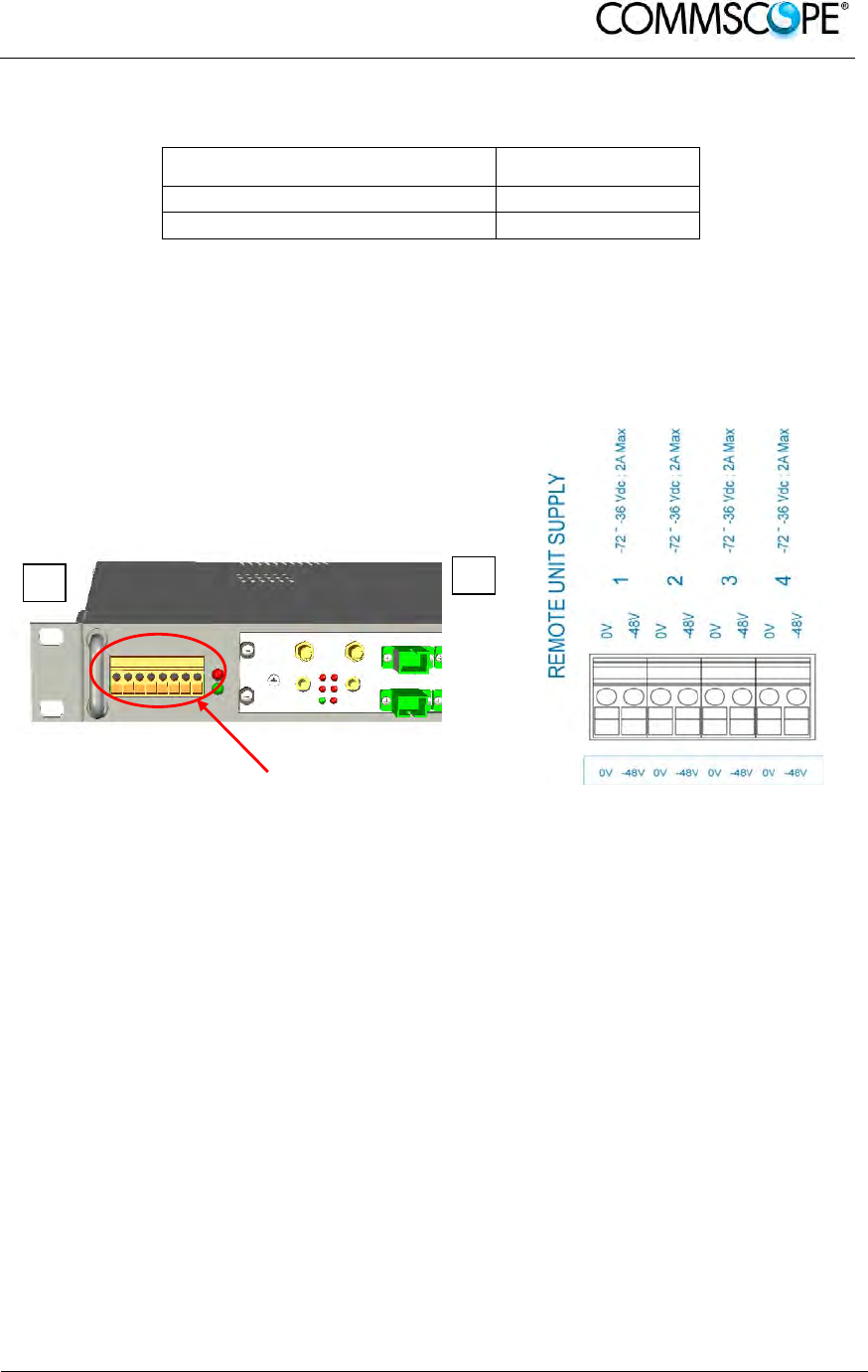
User’s Manual for ION-B Systems
ION-B User Manual (MN024-
15)_n_20150730.docx Page 151
In no such case, dip-switch 8 can be set to OFF.
485 Bus Termination Load Dip-switch 8
Not connected OFF
Connected ON
table 6-8 Setting the 485 Bus termination load with dip-switch 8
6.2.5.3. Power Supplying Ports
The front side of the TPRF31 Fast MiniRack is provided with 4 power supplying
ports, conveying the -48Vdc power supply to up to 4 ION-B Remote Units.
Figure 6-18 TPRF31 Power supplying ports on TPRF31 front side (a), Connection
scheme of the power supply ports (b)
Please refer to relevant bulletin in order to check that the overall maximum power the
TPRF31 provides to your Remote Units is below the overall maximum power
supported by the unit.
6.2.5.4. Auxiliary Inputs
The rear side of the TPRF31 Fast MiniRack is provided with two auxiliary input
alarms, allowing the monitoring of the alarm status (on/off) of any external device.
The alarm status is able to be associated either with the open-circuit or the closed-
circuit status by properly setting the TPRF31 page of the TSUN Supervision
Interface.
Auxiliary input connectors are Phoenix Contact MC1,5-2-G-3.5 connectors working
with typical current rating.
a b
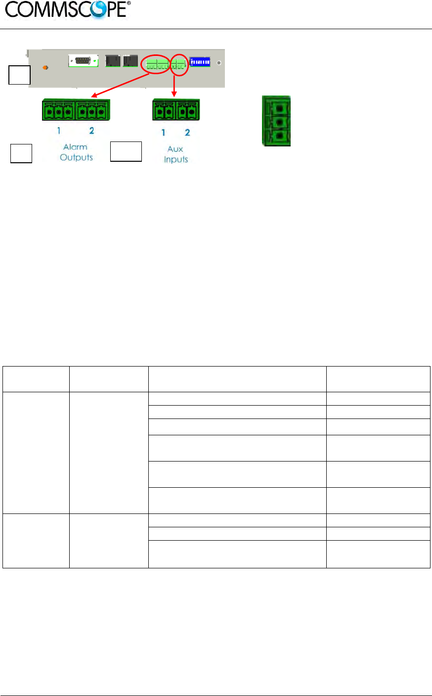
User’s Manual for ION-B Systems
Page 152 ION-B User Manual (MN024-15)_n_20150730.docx
b c *
Normally Closed (to CC)
Normally Open (to CC)
Common Contact (CC)
Figure 6-19 External Alarm Outputs (b) and
Auxiliary Inputs (c) on the TPRF31 rear side (a) Figure 6-20 Description of the
External Alarm Outputs
* Alarm Outputs 1 and 2 (c) refer to Major and Minor alarms, respectively
6.2.5.5. External Alarms
The rear side of the TPRF31 Fast MiniRack is provided with two Alarm-output dry-
contacts, which are able to provide alarm information about Major Alarms and Minor
Alarms (see Figure 6-19 External Alarm Outputs (b) and Auxiliary Inputs (c) on the
TPRF31 rear side (a)).
A full description of these Major and Minor Alarms is provided in table 6-9 Alarm
information available through external alarm contacts.
External Alarm Outputs are Phoenix Contact MC1, 5-3-G-3.5 connectors.
Alarm
Output N° Description Active Alarm Severity
1 Major and
Critical
alarms
None ---
I2CBus alarm Critical
Vcc Major
Slot 1 does not host a card and is
not masked Critical
Slot 2 does not host a card and is
not masked Critical or Major
At least one sub-system unit has
a critical or major alarm Major
2 Minor and
Warning
alarms
None ---
Temperature Warning
At least one sub-system unit has
a critical or major alarm Minor or Warning
table 6-9 Alarm information available through external alarm contacts
a

User’s Manual for ION-B Systems
ION-B User Manual (MN024-
15)_n_20150730.docx Page 153
6.2.6. Warnings - recommended when designing or installing
6.2.6.1. Installation site features
TPRF31 minirack for safety and security scopes, shall be installed on
telecommunication rooms where there is a restricted access permission.
6.2.6.2. Providing correct heat dissipation
For correct use of the TPRF31 subrack, it is important to verify that:
• in case TPRF31 has been mounted in a vertical position (please refer to the
“TPRF31 Installation” section) the power supplying ports (located on the
TPRF31, front side, Figure 6-18 TPRF31 Power supplying ports on TPRF31
front side (a), Connection scheme of the power supply ports (b)) have been
turned upwards.
• in case TPRF31 has been mounted on a rack (please refer to the TPRF31
Installation section), a minimum distance of 1 HE has been kept between
nearby TPRF mini-racks to ensure proper heat dissipation.
6.2.6.3. Setting the dip-switches in a multi subrack system
If you are installing a multi-subrack system, remember to assign each subrack an
exclusive binary address by properly setting dip-switches 1, 2, 3, 4, 5 on the TPRF31
backplane (see Figure 6-17 Dip-switches on the TPRF31 backplane and table 6-7
Dip-switches address settings). Dip-switch 5 has to be set on each TPRF minirack in
order to fix the baud rate for the RS485 and RS232 ports.
Connecting the TPRFs through the RS485 port is necessary when supervising the
whole multi subrack system via the remote supervision unit (to be set at the same
baud rate).
6.2.6.4. Safety
When installing the TPRF31 mini-rack take care of the following safety issues:
• earth protection (screw on the rear panel) has to be provided before
connecting the power supply cables
• an external disconnecting switch, presenting an overcurrent protection of 16 A
max, shall be added
• the on/off switch on the rear panel does not disconnect the power supply to
the Remote Units (front connectors, Figure 6-18 TPRF31 Power supplying
ports on TPRF31 front side (a), Connection scheme of the power supply ports
(b))
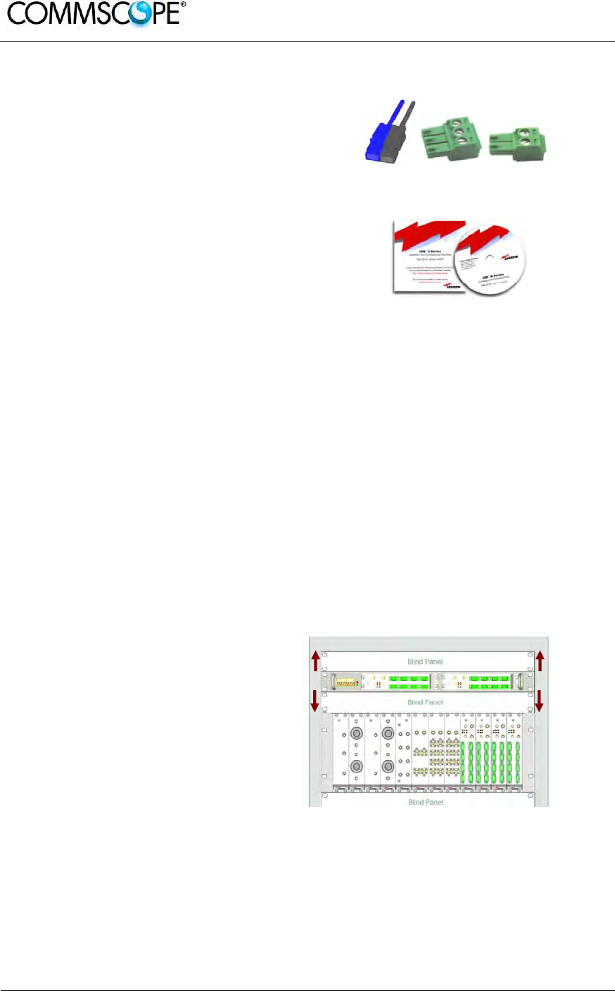
User’s Manual for ION-B Systems
Page 154 ION-B User Manual (MN024-15)_n_20150730.docx
6.2.7. TPRF31 Installation
The TPRF31 installation accessory kit
provides:
• 1 TPRF31 subrack
• 1 power supply cable (a)
• 1 standard RS232 cable
(male-female)
• 2 Alarm-output connectors,
3-pole (b)
• 2 Auxiliary input connectors,
2-pole (c)
• 1 CD-rom, including ION-B manuals
and tools (d)
(a) (b) (c)
(d)
Figure 6-21 Some of the installation
accessories provided with the TPRF31
The TPRF31 Fast MiniRack is provided with some reversible brackets and suitable
both for rack-mounting and for wall-mounting.
Straight from the factory, the TPRF31 has brackets for rack-mounting which can be
turned for wall mounting as described in the following section.
6.2.7.1. Mounting the TPRF31 in a rack
At first, insert the subrack into the cabinet, and fasten it with four screws.
To correctly install the TPRF31, the distance between the front door of the rack and
the front side of the TPRF31 should be at least 15 cm, otherwise optical cables and
(if present) RF cables might be damaged when the cabinet door is closed.
Leave at least 1 HU distance
between the TPRF31 Fast
MiniRack and any other subrack
element, in order to facilitate air
circulation.
Leave at least a 1 HU of free
space between the bottom or the
top of the cabinet and the
TPRF31s.
Figure 6-22 Rack-mounted Fast MiniRack,
configuration example
1HU 1HU
1HU 1HU
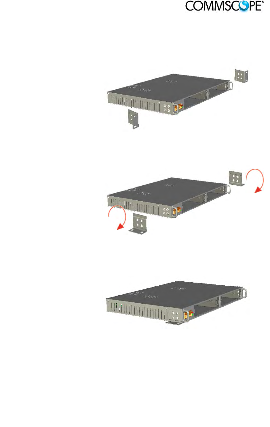
User’s Manual for ION-B Systems
ION-B User Manual (MN024-
15)_n_20150730.docx Page 155
6.2.7.2. Mounting the TPRF31 to a wall
To adapt the rack-mounting brackets for wall mounting, proceed as follows:
Remove the brackets of the
TPRF31 Fast MiniRack,
starting from the factory
configuration.
Figure 6-23 Removal of brackets
Turn the brackets.
Figure 6-24 Turning the brackets
Fasten the brackets properly.
Figure 6-25 Brackets adapted for wall-mounting
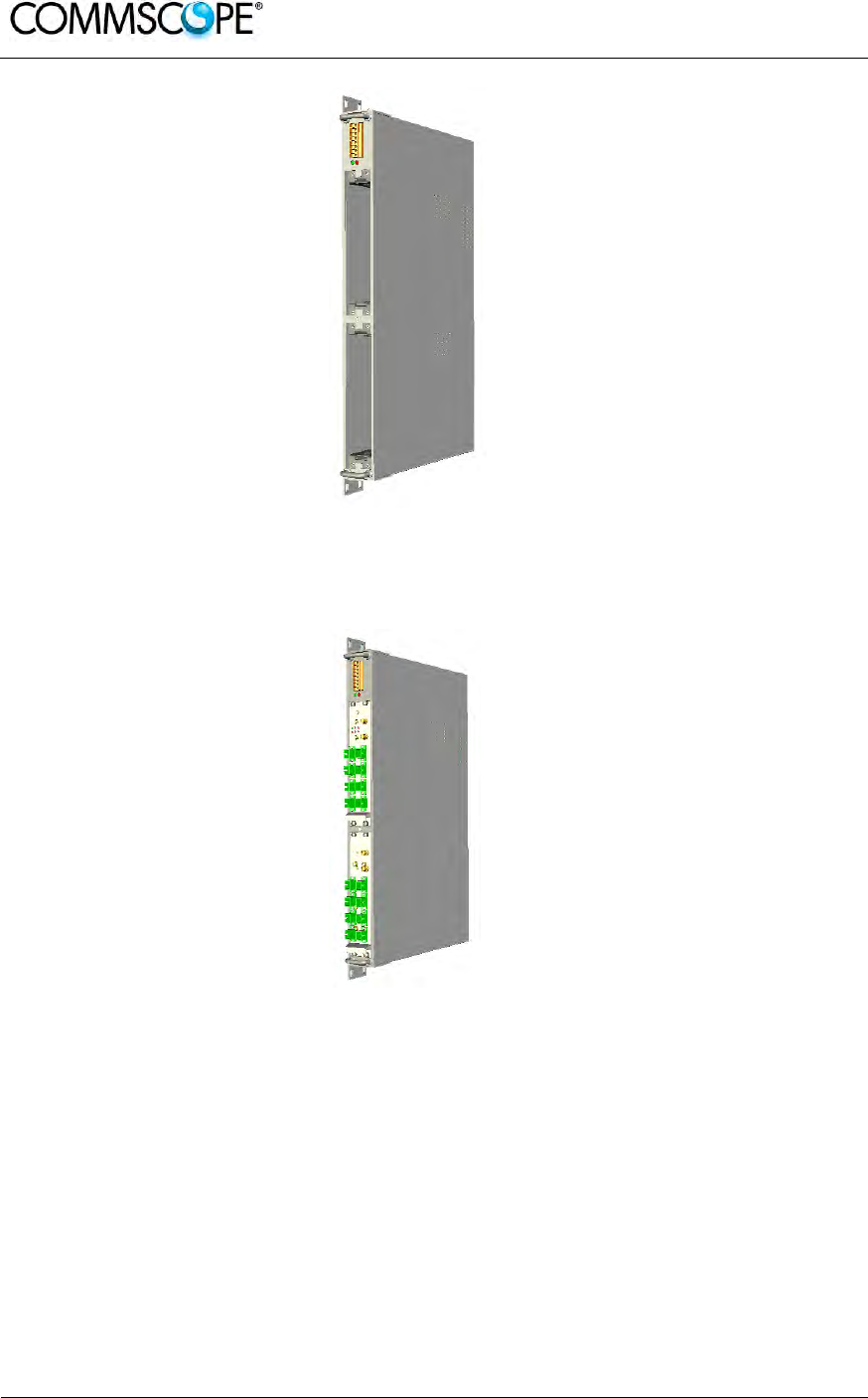
User’s Manual for ION-B Systems
Page 156 ION-B User Manual (MN024-15)_n_20150730.docx
The TPRF31 Fast MiniRack is
ready for wall-mounting.
Figure 6-26 Fast MiniRack adapted for wall-
mounting
Drill four holes according to
the mechanical layout in
Figure 6-28 Mechanical layout
for wall-mounting the TPRF31
Fast MiniRack
Insert the four dowels into the
holes, then fasten the
TPRF31 firmly to the wall by
tightening the screws into the
dowels.
Figure 6-27 Wall-mounted TPRF31 Fast MiniRack,
hosting 2 TFLNs master unit transceivers
Note: It is strongly suggested to mount the TPRF31 with the power
supplying ports turned upwards.
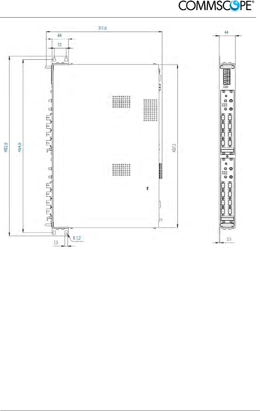
User’s Manual for ION-B Systems
ION-B User Manual (MN024-
15)_n_20150730.docx Page 157
Figure 6-28 Mechanical layout for wall-mounting the TPRF31 Fast MiniRack

User’s Manual for ION-B Systems
Page 158 ION-B User Manual (MN024-15)_n_20150730.docx
6.2.8. TPRF31 Start-Up
Before switching on the TPRF31 minirack, make sure that:
• all the expected modules have been inserted
• the modules have been connected to each other by RF jumpers, according to
what has been planned during the system design
• every TFLN contained in the Master Unit has been connected to its TFAx
Remote Units
• each TFAx Remote Unit has been connected to its coverage antennas
• the remote supervision unit (if present) has been connected or housed to the
Master Unit
• different subracks have been connected to each other via an RS485 bus and
each of them have different addresses
• the rack housing the TPRF31 is large enough to leave a minimum distance of
1 HU between contiguous TPRF31 subracks
Remember that TFAx Remote Units should be switched on before relevant Master
Units.
Once the TPRF31 minirack has been switched on, the system behaviour can be
summarized by the following steps:
• About 10sec after the TPRF31 minirack has been switched on, any TFLN
modules housed in the TPRF itself begin a “discovery” phase in order to identify
and collect the status of the connected TFAx Remote Units. While the discovery
phase is proceeding (max. 4minutes depending on the system complexity) each
TFLN general alarm (i.e., LED “ ”) blinks, whereas the other TFLN LEDs go on
showing the detected status.
Do not connect/disconnect any cable or piece of equipment until all TFLN
modules have finished the discovery phase. This may result in failing to identify
the Remote Units. Nevertheless, during the discovery phase, the entire system
continues to work correctly as the discovery process aims to collect information
about the Remote Units without affecting basic system functionalities.
• Once discovery has finished, the general alarms (i.e. the LED “ ”) on each
TFLN panel stop blinking and switch OFF (provided that the TFLN master
optical TRX is not affected by a general failure).

User’s Manual for ION-B Systems
ION-B User Manual (MN024-
15)_n_20150730.docx Page 159
6.2.9. TPRF31 Troubleshooting
In case a TPRF31 minirack shows any problems, more detailed status and alarm
descriptions can be provided via the remote supervision unit.
A complete overview of the TPRF31 alarms is reported in the following table.
Alarm code
(TSUN
description
)
Alarm description LED
Colour Severity Alarm
output
**
Temperature Over-temperature Alarm - Warning 2
I2CBus
alarm Internal I2Cbus communication
malfunctioning Red Critical 1
Vcc Power supply degradation, with
internal voltage falling below critical
threshold Red Major 1
Summary
Slot 1 The TPRF31 slot 1 is not masked, in
spite of not hosting any card Red Critical 1
Summary
Slot 2 The TPRF31 slot 2 is not masked, in
spite of not hosting any card Red Critical 1
Auxiliary
Input 1 The auxiliary input 1 is in alert status * Red Major 1
Auxiliary
Input 2 The auxiliary input 2 is in alert status * - Minor 2
* (Default alert status is “Closed”, but can be set differently through TSUN Supervision unit)
** The “Alarm output” field indicates the number of the External Alarm Output through which the alarm
information is revealed
table 6-10 Description of the alarms of the TPRF31 subrack
Please note that:
• The power supply degradation (Vcc) occurs in case the +12Vdc power falls
below the critical threshold level. In this case, the TPR31 automatically turns to
standby mode so that no over-current is able to get through the circuitry of
hosted modules, thus switching off the active modules and preserving the
system’s integrity. As soon as the power supply voltage is restored to its
standard level, the TPRF31 automatically turns on the active cards again.
Should this not happen, press the Reset button (see Figure 6-15 Rear view of
the TPRF31 Fast MiniRack: Reset and Store/Clear buttons).
• An I2Cbus alarm occurs when the TPRF31 minirack cannot communicate with
one or more hosted modules. Each TPRF31 slot is able to automatically detect
the presence of a module inside the slot. If a module is detected, but the
TPRF31 is not able to communicate with it, the I2Cbus alarm is activated.

User’s Manual for ION-B Systems
Page 160 ION-B User Manual (MN024-15)_n_20150730.docx
Note: During the system commissioning, remember to mask the unused
slots by pressing the Store/Clear button (Figure 6-15 Rear view of
the TPRF31 Fast MiniRack: Reset and Store/Clear buttons) or via
the LMT software (please refer to the relevant manual for more
information) to avoid triggering insignificant alarms.
Before carrying out any troubleshooting procedures, please check the LMT or
Supervision System manuals.
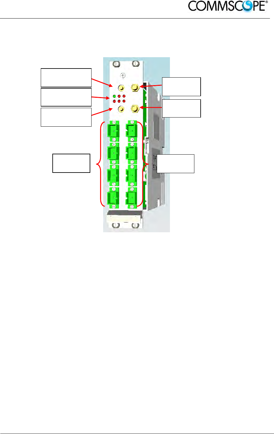
User’s Manual for ION-B Systems
ION-B User Manual (MN024-
15)_n_20150730.docx Page 161
6.3. MASTER OPTICAL TRX, TFLN
6.3.1. Main Tasks Carried Out by the TFLN Module
Figure 6-29 The TFLN Master Optical Transceiver
Downlink (DL)
• RF-to-optical conversion of the input RF signal
• Optical splitting: input RF signal is split onto 4 optical outputs
Uplink (UL)
• Optical-to-RF conversion of the 4 input optical signals
• Automatic Gain Control (AGC) of each converted signal to compensate optical
losses;
• RF combining of the 4 adjusted signals into a single RF output
6.3.2. RF Ports
• 1 DL RF input port and 1 UL RF output port
• 1 auxiliary DL RF input port and 1 auxiliary UL RF output port
Note: Nominal input levels required at RF ports is +10dBm (please refer to
relevant bulletin for further information), as well as RF outputs may
require a power adjustment to fill within the BTS receiving range.
In order to fulfil these requirements, external UL and DL attenuations may be
required.
RF UL Auxiliary
Port
Status and
Alarm LEDs
RF DL Auxiliary
Port
UL Optical
Ports
RF UL
Main Port
RF DL
Main Port
DL Optical
Ports

User’s Manual for ION-B Systems
Page 162 ION-B User Manual (MN024-15)_n_20150730.docx
6.3.3. Optical Ports
• 4 DL optical output ports (SC/APC)
• 4 UL optical input ports (SC/APC)
6.3.4. TFLN Visual Alarms
The TFLN front panel is provided with 6 LEDs (see right), showing status and alarm
information.
Figure 6-30 Visual alarms on the TFLN Master Optical Transceiver
LED significance is reported in the table below.
Label LED
colour Significance
= Green Power supply status OK
Red General TFLN failure, it might be:- TFLN laser failure
- UL or DL amplifier failure
- TFLN short circuit
1 Red
Low UL optical power received from Remote Unit 1 (fault in
optical link 1 or Remote Unit 1 failure)
2 Red
Low UL optical power received from Remote Unit 2 (fault in
optical link 2 or Remote Unit 2 failure)
3 Red
Low UL optical power received from Remote Unit 3 (fault in
optical link 3 or Remote Unit 3 failure)
4 Red
Low UL optical power received from Remote Unit 4 (fault in
optical link 4 or Remote Unit 4 failure)
table 6-11 Visual alarms on the TFLN Master Optical Transceiver
Further information about alarm status is delivered by the ION-B Supervision System.
Note: In case the four TFLN optical output ports are not all connected to
Remote Units, the unused ports must be properly masked at
commissioning in order to avoid spurious alarms (please refer to
LMT manual).
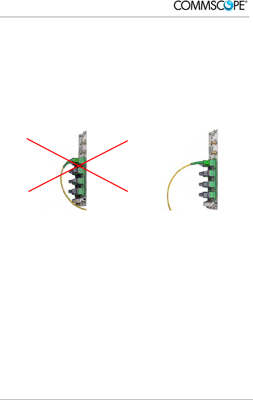
User’s Manual for ION-B Systems
ION-B User Manual (MN024-
15)_n_20150730.docx Page 163
6.3.5. TFLN Power Supply
Each TFLN master optical TRX is supplied by the subrack backplane (12V).
6.3.6. Warnings - to be read before TFLN installation
6.3.6.1. Dealing with optical output ports
The TFLN master optical TRX contains semiconductor lasers. Invisible laser beams
may be emitted from the optical output ports. Do not look towards the optical ports
while equipment is switched on.
6.3.6.2. Handling optical connections
Figure 6-31 Wrong handling of fiber
optical bending Figure 6-32 Correct handling of fiber
optical bending
• When inserting an optical connector, take care to handle it in order not to
damage the optical fibre. Optical fibres have to be single-mode (SM)
9.5/125μm.
• Typically, ION-B equipment is provided with SC-APC optical connectors.
Inserting any other connector will result in severe damages.
• Do not force or stretch the fibre pigtail with a radius of curvature less than 5
cm. See Fig. 19 for optimal fibre cabling.
• Remove adapter caps only just before making connections. Do not leave SC-
APC adapters open, as they attract dust. Unused SC-APC adapters must
always be covered with their caps.
• Do not touch the adapter tip. Clean it thoroughly before inserting each
connector into the sleeve. In case adapter tips need to be cleaned better, use
pure ethyl alcohol
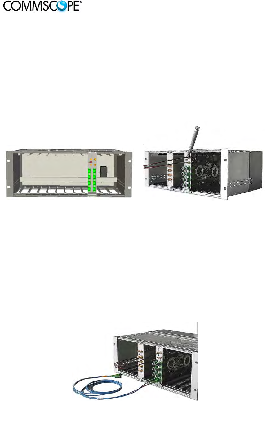
User’s Manual for ION-B Systems
Page 164 ION-B User Manual (MN024-15)_n_20150730.docx
6.3.6.3. Inserting or removing TFLN modules
• Do not remove or insert any TFLN module into TPRN subrack before having
switched off main power supply.
• The TFLN modules must be handled with care, in order to avoid damage to
electrostatic sensitive devices.
• When installing TFLN modules in the subrack, take care to alternate active
and passive cards in order to ensure proper heat dissipation.
• In a multi-subrack system, remember to assign to each subrack a proper
RS485 bus address before installing the modules (please refer to Rack-Based
Master Unit section for further details).
Figure 6-33 Installing a TFLN module Figure 6-34 Proper cabling of SMA
connectors on a TFLN front panel
TFLN Positioning
• In case no ventilation system has been installed, don’t insert more than 8
TFLN modules into the subrack.
• In case more than 8 TFLN modules have to be housed in a TPRN subrack, it’s
advisable to install the TPRN subrack inside a rack with forced ventilation.
• Be careful to meet expected requirements for RF ports. An adjustable
attenuator might be necessary if the power coming from the BTS exceeds the
required levels, to avoid damaging the ION-B circuitry or an increase of
spurious emissions.
Figure 6-35 Visual alarms on the TFLN Master Optical Transceiver.

User’s Manual for ION-B Systems
ION-B User Manual (MN024-
15)_n_20150730.docx Page 165
6.3.7. TFLN Installation
The TFLN master optical TRX is housed in a TPRN subrack and its dimensions are 7
TE wide and 4HE high. A TFLN module is able to be accommodated in any of these
12 slots.
Note: In case a new TFLN module has to be installed in a still working
Master Unit, switch off the subrack before inserting the plug-in
TFLN module.
Firstly, gently insert the TFLN into one of the 12 available slots, and lock the 4
screws on the front corners.
Then, connect the UL and DL RF cable to the TFLN UL and DL ports, respectively.
Use an appropriate torque wrench to fix these RF cables to DL and UL ports.
Remove the caps from TFLN optical ports and connect the SC-APC fibre optic cables
to the ports.
UL and DL cables coming from the same Remote Unit have to be connected to the
UL and DL ports marked by the same number on the TFLN front panel.
As you switch on the system, carefully refer to the TFLN Start-Up section.
Remember that Remote Units should be switched on before the Master Unit in order
to follow the correct Start-Up procedure.
Label LED colour Status
= Green
ON
(power supply is on)
Red OFF
(no major failure affects TFLN operations)
1 Red
OFF
(no major failure affects corresponding
Remote Unit or UL connection)
2 Red
OFF
(no major failure affects corresponding
Remote Unit or UL connection)
3 Red
OFF
(no major failure affects corresponding
Remote Unit or UL connection)
4 Red
OFF
(no major failure affects corresponding
Remote Unit or UL connection)
table 6-12 LED alerts on the TFLN front panel

User’s Manual for ION-B Systems
Page 166 ION-B User Manual (MN024-15)_n_20150730.docx
6.3.8. TFLN Start-Up
Before the Master Unit is switched on, make sure that:
• all necessary modules have been inserted into the Master Unit
• the modules have been connected each other by RF jumpers, according to
what has been planned in the system design
• every TFLN master optical TRX has been connected to the relevant Remote
Units
• each Remote Unit has been connected to its coverage antenna
• the remote supervision unit, if present, has been connected to the Master Unit
• different Master Units are connected to each other via bus RS485
Following this, the Master Unit itself can be turned on, making sure to turn on all the
Remote Units first,
Once the Master Unit has been switched on, the behaviour of the TFLN at system
start-up is able to be summarized with the following steps:
1. When the Master Unit is turned on, all six LEDs on the TFLN front panel
remain lit for a couple of seconds. After that, the green LED remains lit (indicating
proper power supply) while the other LEDs indicate the master optical TRX status,
according to the following table.
Note: If the unused optical ports of the TFLN haven’t been masked
through the LMT yet, corresponding LEDs will be lit. If this is the
case, wait for the end of step 3 (discovery phase) then use the LMT
to mask them (please refer to relevant manual).
2. About 10 seconds after the system has been switched on, the TFLN module
begins a “discovery” phase to identify all connected Remote Units. This operation
serves to collect all necessary information to be provided to the Supervision System.
During the discovery phase, the TFLN general alarm (LED “ “) blinks while the
other LEDs go on showing their previously detected status’. Time dedicated to the
discovery phase could be up to a maximum of 4 min. and depends on system
complexity.
Note: Do not connect/disconnect any cable or any piece of equipment
during the discovery phase. This may result in failing to identify
Remote Units.
Please note that, while the discovery phase is running, the whole system is working
correctly as discovery operations aim only to collect information about Remote Units
without affecting the system functionalities.
Note: In case discovery doesn’t start automatically, check the LMT or the
remote supervision whether it has been disabled (refer to the LMT
or remote Supervision System manuals for further information).

User’s Manual for ION-B Systems
ION-B User Manual (MN024-
15)_n_20150730.docx Page 167
Once the discovery is finished, the TFLN general alarm (LED “ ”) stops blinking and
switches OFF. The power supply LED (green) remains on while LEDs 1, 2, 3 and 4
show either the status of the Remote Units or the quality of the UL connections.
In case some of these LEDs remain on, check if they refer to unused optical ports or
not. In this case, use LMT software to mask it. Otherwise, if they refer to connected
Remote Units and remain on, please refer to the troubleshooting procedures.
6.3.9. Removing a TFLN Module
Switch off the Master Unit power supply, remove the SC-APC optical connectors, and
insert the protection caps into the TFLN optical ports.
Then:
• unscrew the 4 screws and slowly remove the card
• put the removed TFLN card in its safety box
• switch the Master Unit power supply on again, and refer to the TFLN Start-Up
section.
6.3.10. TFLN Troubleshooting
In case a TFLN master optical TRX has any problems, this will be easily revealed
through the LEDs on its front panels, otherwise troubleshooting can be carried out
through the LMT or the Supervision System.
LEDs on the TFLN front panel detect not only failures on the TFLN board itself, but
also reveal malfunctions located on related Remote Units.
The below table reports a brief description of the TFLN alarms, together with a
reference to the corresponding alerted LEDs.
As the table shows, LEDs on the TFLN front panel signal all high priority alarms while
minor alarms, which detect critical situations which should be checked and tested in
order to avoid future possible system faults, are only revealed by the LMT or the
Supervision System.
Alarm Code
(TSUN
description) Alarm description Active
LED
Supervision
Priority
Level
Action
Recommended
Relé
Priority
Level
RX1 optical
power fail
The optical power
received on the
UL1 is too low and
can’t no more be
compensated
RED
(LED1) CRITICAL
Check the UL1
fibre and the
Remote Unit
laser status
MAJOR
RX1 AGC out
of range
The optical power
received is under
the allowed 3dB
optical loss but it
can be
compensated
NONE MINOR Clean optical
connectors MINOR
RX2 optical
power fail
The optical power
received on the
UL2 is too low and
can’t no more be
compensated
RED
(LED2) CRITICAL
Check the UL2
fibre and the
Remote Unit
laser status
MAJOR

User’s Manual for ION-B Systems
Page 168 ION-B User Manual (MN024-15)_n_20150730.docx
Alarm Code
(TSUN
description) Alarm description Active
LED
Supervision
Priority
Level
Action
Recommended
Relé
Priority
Level
RX2 AGC out
of range
The optical power
received is under
the allowed 3dB
optical loss but it
can be
compensated
NONE MINOR Clean optical
connectors MINOR
RX3 optical
power fail
The optical power
received on the
UL3 is too low and
can’t no more be
compensated
RED
(LED3) CRITICAL
Check the UL3
fibre and the
Remote Unit
laser status
MAJOR
RX3 AGC out
of range
The optical power
received is under
the allowed 3dB
optical loss but it
can be
compensated
NONE MINOR Clean optical
connectors MINOR
RX4 optical
power fail
The optical power
received on the
UL4 is too low and
can’t no more be
compensated
RED
(LED4) CRITICAL
Check the UL4
fibre and the
Remote Unit
laser status
MAJOR
RX4 AGC out
of range
The optical power
received is under
the allowed 3dB
optical loss but it
can be
compensated
NONE MINOR Clean optical
connectors MINOR
Major Remote
Unit 1 Alarm from RU1 RED
(LED1) - Check Remote
Unit status MAJOR
Major Remote
Unit 2 Alarm from RU2 RED
(LED2) - Check Remote
Unit status MAJOR
Major Remote
Unit 3 Alarm from RU3 RED
(
LED3
)
- Check Remote
Unit status MAJOR
Major Remote
Unit 4 Alarm from RU4 RED
(LED4) - Check Remote
Unit status MAJOR
DL laser
alarm A fault occurs on
the DL laser RED ( ) MAJOR Return the unit MAJOR
UL RF alarm HW failure on the
UL RF section RED ( ) MAJOR Return the unit MAJOR
DL RF alarm HW failure on the
DL RF section RED ( ) CRITICAL Return the unit MAJOR
Board failure
alarm General failure on
board RED ( ) MAJOR Return the unit MAJOR
Temperature
alarm Over-temperature
alarm NONE MINOR Check ventilation
and environment MINOR
table 6-13 LED alerts on the TFLN front panel

User’s Manual for ION-B Systems
ION-B User Manual (MN024-
15)_n_20150730.docx Page 169
Each TFLN is provided with an AGC system which
compensates optical losses of <3 dB. TFLN LED
alarms switch on when the estimated optical losses
are >4dB, when the AGC is not able to compensate
these losses any more.
Figure 6-36 AGC thresholds
vs LED alerts
One of LEDs,1, 2, 3 or 4, might turn on not only to indicate a high optical loss
detected by the TFLN, but also to reveal a Remote Unit failure. Understanding the
reason why one of LEDs 1, 2, 3 or 4 is on (a Remote Unit failure, an optical cable
fault or an external equipment malfunction) can be done following the troubleshooting
procedure reported hereinafter.
6.3.10.1. Quick Troubleshooting Procedure
The following procedure is summarized by the flow-chart in Figure 6-37 Flow-chart
describing the quick troubleshooting procedure.
1. If the TFLN general alarm (LED “ “) is on, replace the faulty TFLN master
optical TRX with a new one and contact the manufacturer for assistance.
2. In case one of the LEDs, 1, 2, 3 or 4, is lit, the corresponding TFLN adapter
might be dirty. Try cleaning it using pure ethyl alcohol. If the LED is still lit, go to the
corresponding Remote Unit side and check the red LED on the TFAx warm side:
a. If it is off, the optical cables or the optical connections are supposed to
have some problem on UL path. Refer to Fibre Optic UL
Troubleshooting.
b. If it is on, refer to Remote Unit troubleshooting presented in the previous
Remote Unit section
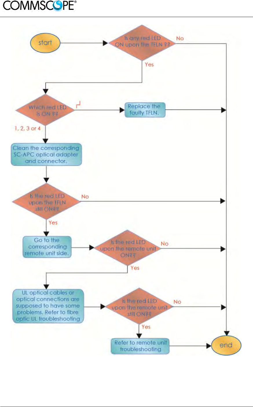
User’s Manual for ION-B Systems
Page 170 ION-B User Manual (MN024-15)_n_20150730.docx
Figure 6-37 Flow-chart describing the quick troubleshooting procedure

User’s Manual for ION-B Systems
ION-B User Manual (MN024-
15)_n_20150730.docx Page 171
6.3.10.2. Fibre Optic UL Troubleshooting
The following procedure is summarized by the flow-chart Figure 6-38 Flow-chart
describing the quick troubleshooting procedure.
1. Check if there is any point where the fibre experiences a small radius of
curvature. In this case, rearrange the optical path in order to avoid sharp bends (if
necessary, replace the optical cable with a longer one). If this causes the TFLN red
LED to switch off, troubleshooting has been successful. Otherwise, follow this next
step.
2. Check if the SC-APC connectors are properly installed at both fibre ends (i.e.
TFLN and TFAx ports). If not, fix the SC-SPC connectors better to their relevant
adapters. If this causes the TFLN red LED to switch off, troubleshooting has been
successful. Otherwise, follow this next step.
3. Disconnect the optical fibre and clean it at both fibre ends (i.e. TFLN side and
TFAx side) then reconnect the fibre to relevant ports. In case this causes the TFLN
red LED to switch off, troubleshooting has been successful. Otherwise, follow the
next step.
4. Disconnect the optical SC-APC connector from TFLN UL port, and measure
the output power POUT(UL) at the corresponding fibre end. Then, go to the TFAx
side, disconnect the optical SC-APC connector from TFAx UL port and measure the
input power PIN(UL) coming out of the TFAx UL port.
5. Calculate the UL fibre attenuation AUL as: AUL [dB] = PIN(UL) – POUT(UL)
a. If AUL > 4dB, the fibre optic cable has some problems or the cable path
is too long. Replace it.
b. If AUL < 4dB, then the TFAx Remote Unit could be faulty. Before
replacing it, check the TFAx status on the Supervision System and
contact for assistance
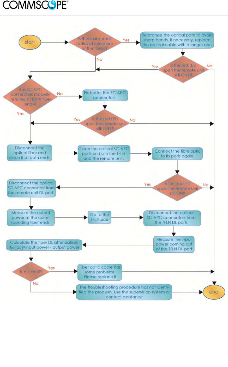
User’s Manual for ION-B Systems
Page 172 ION-B User Manual (MN024-15)_n_20150730.docx
Figure 6-38 Flow-chart describing the quick troubleshooting procedure
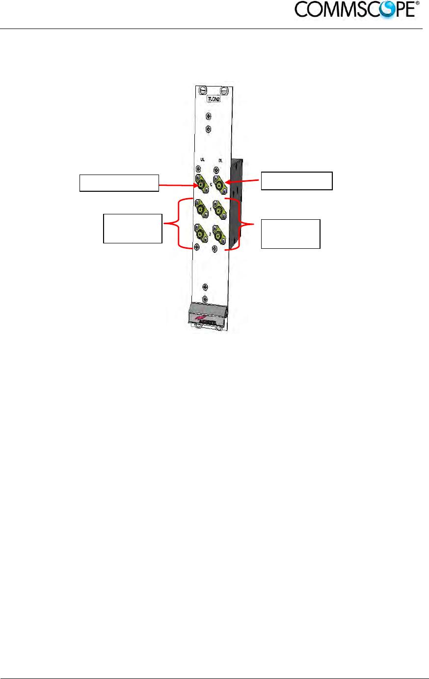
User’s Manual for ION-B Systems
ION-B User Manual (MN024-
15)_n_20150730.docx Page 173
6.4. TWO-WAY SPLITTER/COMBINER, TLCN2-W
6.4.1. Description
Figure 6-39 TLCN2-W splitter/combiner
The TLCN2-W, a bidirectional 2-way splitter/combiner, provides two identical
combining sections for UL and DL which can be used in the following ways:
• to combine 2 RF signals into a common RF output
• to split an RF input into 2 RF output signals
It is a passive wideband module
6.4.2. RF Ports
• 1 DL common RF port (“C”)
• 2 DL split RF ports (“1”,“2”)
• 1 UL common RF port (”C”)
• 2 UL split RF ports (“1”,“2”)
Note: Each port is bidirectional.
UL Common
UL
Splitted
DL Common
DL
Splitted

User’s Manual for ION-B Systems
Page 174 ION-B User Manual (MN024-15)_n_20150730.docx
6.4.3. TLCN2-W Main Applications
The main applications of the TLCN2-W module are:
• Connecting a donor source to more than one TFLN master optical TRX, so
that:
- TLCN2-W splits the DL input coming from a donor source into 2 output
signals entering 2 different TFLN master optical TRXs
- TLCN2-W combines the UL inputs coming from 2 TFLN master optical
TRXs into 1 common signal entering the donor source
• Connecting a TFLN master optical TRX to more than one donor source within
the same service, so that:
- TLCN2-W combines the two DL inputs coming from 2 donor sources
into 1 output signal entering the TFLN master optical TRX or a cross
band coupler
- TLCN2-W splits the UL input coming from TFLN master optical TRX or
a cross band coupler into 2 different output signals entering 2 different
donor sources.
More TLCN2-W modules can be used in cascade connections.
6.4.4. TLCN2-W-W Insertion Loss
The TLCN2-W insertion loss varies slightly depending on the frequency bands, check
relevant bulleting for the values
6.4.5. Warnings
The overall input power must not exceed +30dBm when combining and +33dBm
when splitting.
6.4.6. TLCN2-W Installation
Since the TLCN2-W module doesn’t require any power supply, it can be housed
either in an active or a passive TPRN subrack.
1. Unpack the kit which includes: 1 TLCN2-W
4 RF jumpers (SMA-m), 2 x 25cm, 2 x 35cm
2. Carefully insert the TLCN2-W module into any of the TPRN subrack slots and
lock the four screws on the front corners.
3. Connect RF cables to the UL and DL ports, according to what has been
planned by the designer. Use an appropriate torque wrench to fasten each
cable to its relevant ports.
4. In case some ports remain unused, remember to connect them to a 50Ω load
(not included)
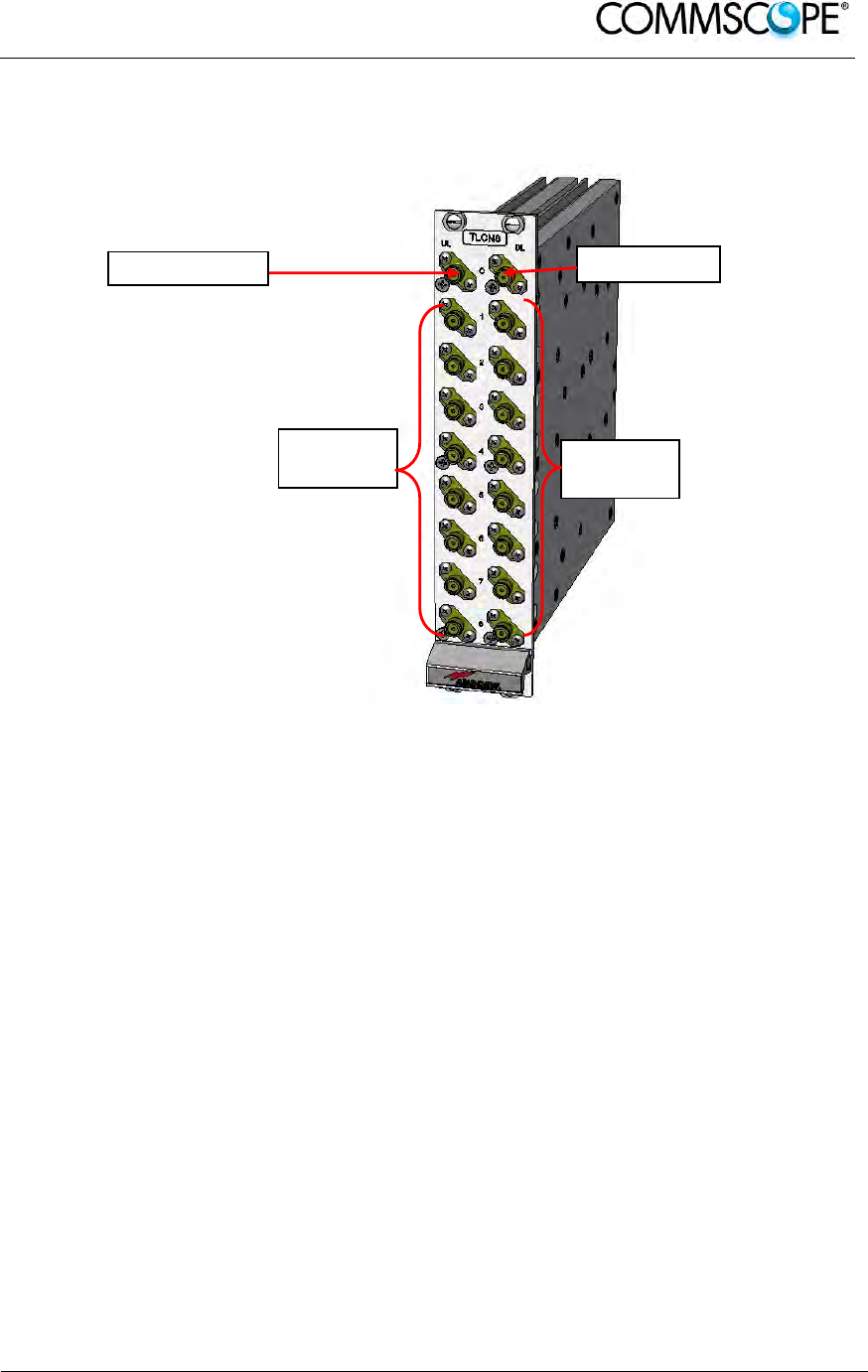
User’s Manual for ION-B Systems
ION-B User Manual (MN024-
15)_n_20150730.docx Page 175
6.5. EIGHT-WAY SPLITTER/COMBINER, TLCN8-W
6.5.1. Description
Figure 6-40 TLCN8-W splitter-combiner
The TLCN8-W is a wideband 8-way RF combiner designed to distribute the signal
coming from a donor source to the optical TRXs of a Master Unit.
The TLCN8-W wideband 8-way RF combiner provides two identical combining
sections for the UL and DL which can be used to:
• combine 8 RF signals into a common RF output
• split an RF input into 8 RF output signals
It is a passive wideband module.
6.5.2. RF Ports
• 1 DL common RF port (“C”)
• 8 DL split RF ports (labelled “1”,“2”,“3”,“4”…)
• 1 UL common RF port (”C”)
• 8 UL split RF ports (labelled “1”,“2”,“3”,“4”…)
Note: Each port is bidirectional.
UL Splitter DL Splitter
UL Common DL Common

User’s Manual for ION-B Systems
Page 176 ION-B User Manual (MN024-15)_n_20150730.docx
6.5.3. TLCN8-W Main Applications
The main applications of the TLCN8-W module are:
• Connecting a donor source to more than one TFLN master optical TRX, so
that:
- TLCN8-W splits the DL input coming from a donor source into 8 output
signals entering 8 different TFLN master optical TRXs
- TLCN8-W combines the UL inputs coming from 8 TFLN master optical
TRXs into 1 common signal entering the donor source
• Connecting a TFLN master optical TRX to more than one donor source within
the same service, so that:
- TLCN8-W combines the two DL inputs coming from up to 8 donor sources
into 1 output signal entering the TFLN master optical TRX.
- TLCN8-W splits the UL inputs coming from the TFLN master optical TRX
into 8 different output signals entering up to 8 different donor sources.
• More TLCN8-W modules can be used in cascade connections.
6.5.4. TLCN8-W Insertion Loss
The TLCN8-W insertion loss varies slightly depending on the frequency bands, check
relevant bulleting for the values
6.5.5. Warnings
The overall input power must not exceed +24dBm when combining and +33dBm
when splitting.
6.5.6. TLCN8-W Installation
Since the TLCN8-W module does not require any power supply it can be housed
either in an active or a passive TPRN subrack.
1. Unpack the kit which includes: 1 TLCN8-W
16 RF jumpers (SMA-m), 2 x 25cm, 12 x
35cm, 2 x 45cm
2. Carefully insert the TLCN8-W module into any of the TPRN subrack slots and
tighten the four screws on the front corners.
3. Connect RF cables to the UL and DL ports, according to what has been
planned by the designer. Use an appropriate torque wrench to fix each cable
to their relevant ports.
4. In case some ports remain unused, remember to connect them to a 50Ω load
(not included)
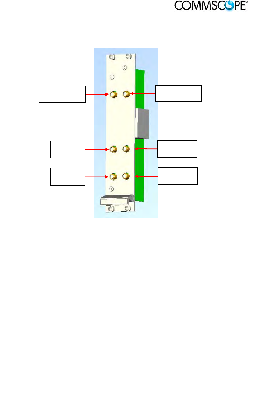
User’s Manual for ION-B Systems
ION-B User Manual (MN024-
15)_n_20150730.docx Page 177
6.6. RF DUAL BAND COUPLER TLDN
6.6.1. Description
Figure 6-41 TLDN dual band duplexer
The TLDN is a passive RF dual band coupler designed to distribute signals within the
master unit when coming from different bands.
Main operations carried out are:
• In downlink, it combines a low band RF signal (800MHz to 1000MHz) and a
high-band RF signal (1700MHz to 2200MHz) into a common RF path.
• In uplink, it filters the composite signal into a low-band (800MHz to 1000MHz)
and a high-band (1700MHz to 2200MHz).
It is a passive module.
6.6.2. RF Ports
• 1 UL common RF input port (“C”) for the combined UL signal
• 1 UL high-band RF output port
• 1 UL low-band RF output port
• 1 DL common RF output port (“C”) for the combined DL signal
• 1 DL high-band RF input port
• 1 DL low-band RF input port
RF UL
port High
RF DL port
High Band
RF UL
Common Port
RF DL
Common Port
RF UL
port
RF DL port
High Band

User’s Manual for ION-B Systems
Page 178 ION-B User Manual (MN024-15)_n_20150730.docx
6.6.3. TLDN Main Applications
Main applications of the TLDN module are:
• Connecting 2 donor sources with different services to one TFLN master optical
TRX in a dual band system, so that:
- the TLDN combines the DL inputs coming from the 2 different donor
sources (carrying different services) into an output signal entering the
TFLN master opticalTRX
- TLDN filters the UL input coming from a TFLN master optical TRX into 2
UL outputs entering 2 different donor sources (carrying different services)
6.6.4. TLDN Insertion Loss
When designing the system, remember to take into account the insertion loss of the
TLDN, check relevant bulletin for the values
6.6.5. Warnings
The overall input power must not exceed +27dBm.
6.6.6. TLDN Installation
Since the TLDN module does not require any power supply, it can be housed either
in an active or a passive TPRN subrack.
1. Unpack the kit which includes: 1 TLDN
2 RF jumpers (SMA-m), 2 x 45cm
2. Carefully insert the TLDN module in any of the TPRN subrack slots and tighten
the 4 screws on the front corners.
3. Connect RF cables to the UL and DL ports, according to what has been
planned by the designer. Use an appropriate torque wrench to fix each cable
to their relevant ports.
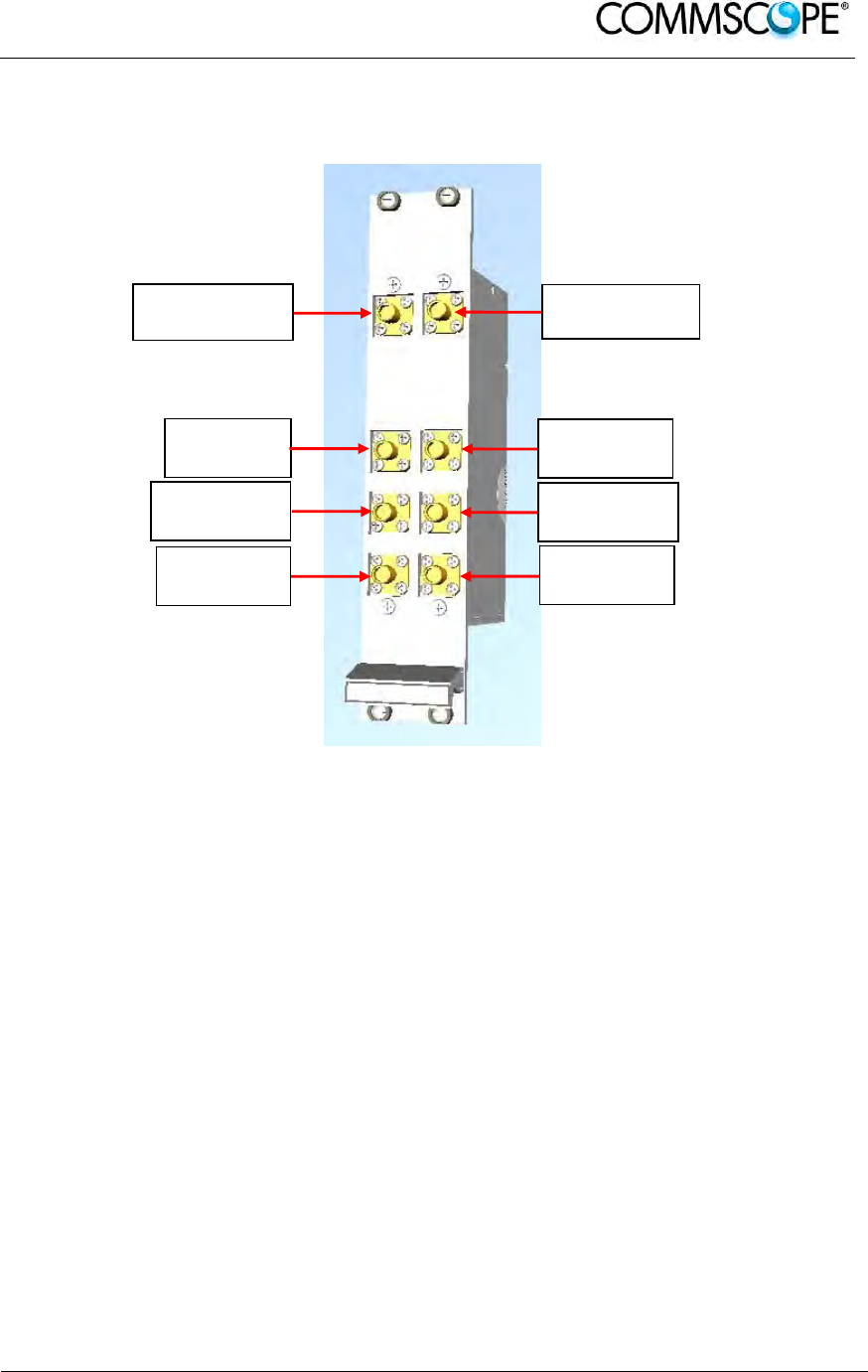
User’s Manual for ION-B Systems
ION-B User Manual (MN024-
15)_n_20150730.docx Page 179
6.7. RF TRI BAND COUPLER TLTN
6.7.1. Description
Figure 6-42 TLTN tri-band coupler
The TLTN is a passive RF tri band coupler designed to combine/split signals coming
from different bands.
Main operations carried out are:
• In downlink, it combines a low-band signal, a middle-band signal and a high-
band signal onto a single RF path.
• In uplink, it filters a composite signal into low-band, a middle-band and a low-
band one.
6.7.2. TLTN Models
The TLTN tri-band combiner is available in different versions, depending on the
bands it addresses. For a list of the TLTN models currently available check relevant
bulletin.
RF UL port
Middle Band RF DL port
Middle Band
RF UL
Common Port RF DL
Common Port
RF UL port
Low Band RF DL port
Low Band
RF UL port
High Band RF DL port
High Band

User’s Manual for ION-B Systems
Page 180 ION-B User Manual (MN024-15)_n_20150730.docx
6.7.3. RF Ports
• 1 DL common RF output port (“C”) for the combined DL signal
• 1 DL Low-Band RF input port
• 1 DL Middle-Band RF input port
• 1 DL High-Band RF input port
• 1 UL common RF input port (“C”) for the combined UL signal
• 1 UL Low-Band RF output port
• 1 UL Middle-BandRF output port
• 1 UL High-Band RF output port
6.7.4. TLTN Main Applications
The main applications of the TLTN module are:
• Connecting three donor sources with different services to one TFLN master
optical TRX in a tri band system, so that:
- the TLTN combines the DL inputs coming from 3 different donor sources
(carrying different services) into an output signal entering the TFLN master
optical TRX
- the TLTN filters the UL input coming from the TFLN master optical TRX into
3 UL outputs entering 3 different donor sources (carrying different services)
6.7.5. TLTN Insertion Loss
When designing the system, remember to take into account the insertion loss of the
TLTN, check relevant bulletin for the values.
6.7.6. Warnings
The overall input power must not exceed +27dBm
6.7.7. TLTN Installation
Since the TLTN module does not require any power supply it can be housed either in
an active or a passive TPRN subrack.
1. Unpack the kit which includes: 1 TLTN
2 RF jumpers (SMA-m), 2 x 45cm
2. Carefully insert the TLTN module in any of the TPRN subrack slots and tighten
the 4 screws on the front corners.
3. Connect RF cables to the UL and DL ports, according to what has been
planned by the designer. Use an appropriate torque wrench to fix each cable
to relevant ports.
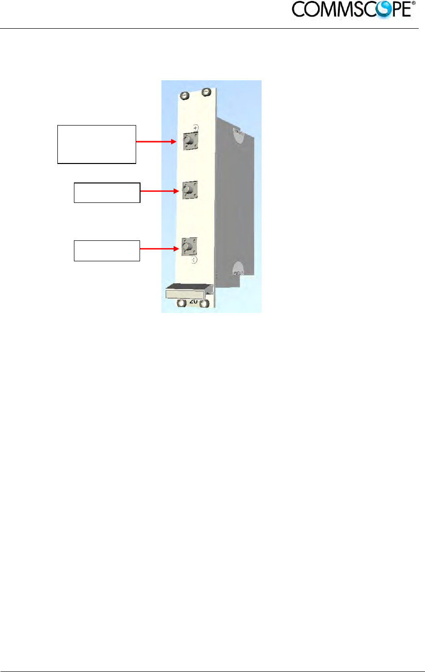
User’s Manual for ION-B Systems
ION-B User Manual (MN024-
15)_n_20150730.docx Page 181
6.8. RF DUPLEXER, TDPN
6.8.1. Description
Figure 6-43 RF duplexer TPDN
The TDPN is a frequency-dependent duplexer which combines downlink and uplink
signals while maintaining isolation and stability. This board has been designed to
support duplexed Base Stations.
6.8.2. TLDN Models
The TLDN is available in different versions, depending on the band it addresses. For
a list of the TLDN models currently available check relevant bulletin.
6.8.3. RF Ports
• 1 DL RF output port
• 1 UL RF input port
• 1 common RF port (“C”) for UL and DL combined signals
6.8.4. TDPN Main Applications
The TDPN main application is to connect the duplexed antenna port of the donor
source to the ION-B system. The TDPN splits the DL and UL signals coming
combined from the donor port into two separated ports.
RF port for
combined UL
and DL si
g
nals
UL RF port
DL RF port

User’s Manual for ION-B Systems
Page 182 ION-B User Manual (MN024-15)_n_20150730.docx
6.8.5. TDPN Insertion Loss
When designing the system, remember to take into account the insertion losses of
the TDPN, check the values on relevant bulletin.
6.8.6. Warnings
The overall input power must not exceed +34dBm.
6.8.7. TDPN Installation
Since the TDPN module doesn’t require any power supply it can be housed either in
an active or a passive TPRN subrack.
1. Unpack the kit which includes: 1 TDPN
2 RF jumpers (SMA-m), 2 x 35cm
2. Carefully insert the TDPN module in any of the TPRN subrack slots and
tighten the 4 screws on the front corners.
3. Connect RF cables to common UL and DL ports, according to what has been
planned by the designer. Use an appropriate torque wrench to fix each cable
to their relevant ports.
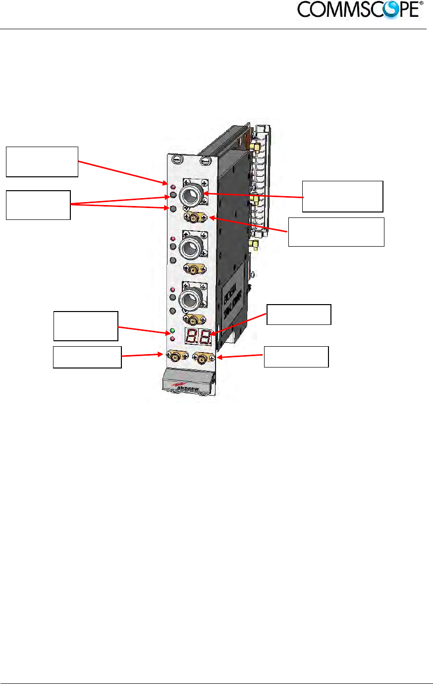
User’s Manual for ION-B Systems
ION-B User Manual (MN024-
15)_n_20150730.docx Page 183
6.9. POINT OF INTERFACE TPOI
6.9.1. TPOI SISO
6.9.1.1. Description
Figure 6-44 TPOI point of interface
The TPOI is an integrated point of interface which enables triple band, applications.
Different configurations are available answering to the possible band combinations.
TPOI includes duplexer, digital adjustable attenuator, downlink automatic level
control (ALC) and cross band coupler functionalities which allows to feed the master
optical TRX with proper levelling.
6.9.1.2. TPOI Models
The TPOI is available in different versions, depending on the band it addresses. For
a list of the TPOI models currently available check relevant bulletin.
6.9.1.3. RF Ports
• 3 TRX RF ports, one for each band
• 3 RX RF ports, one for each band
• 1 DL RF output port
• 1 UL RF input port
Band specific
RX RF
p
orts
Band specific
TRX RF ports
DL RF port UL RF port
Status and
Alarm LEDs
Band specific
Alarm LEDs
Setting
Buttons
Display

User’s Manual for ION-B Systems
Page 184 ION-B User Manual (MN024-15)_n_20150730.docx
6.9.1.4. Setting Buttons and Display
TPOI is provided with two setting buttons for each band which can be used to set
attenuation manually through the following steps:
1. Press DL or UL button according to the attenuation you want to set. Current
value is displayed in the display.
2. Press again the button to start setting procedure: the value on the display start
blinking
3. Use DL button to increase attenuation value and UL button to decrease it
4. Hold again the initial button for more then 3 sec. to have the value stored.
Alternatively attenuation can be set through LMT or supervision system
6.9.1.5. TPOI Visual alarms
The TPOI front panel is provided with 5 LEDs showing status and alarm information.
Two of them are related to the TPOI board while the other three red LED are
reserved for band specific information
LED significance is reported in the table below.
Label LED
colour Significance
= Green Power supply status OK
Red General TPOI failure related to internal power supply failure
Red Indicate band specific alarm:
- Over Power: exceeding absolute maximum input power
- UL RF alarm
Red Indicate band specific alarm:
- Over Power: exceeding absolute maximum input power
- UL RF alarm
Red Indicate band specific alarm:
- Over Power: exceeding absolute maximum input power
- UL RF alarm
table 6-14 LED alerts on the TPOI front panel
Further information about alarm status is delivered by the ION-B Supervision System.
6.9.1.6. TPOI Power Supply
Each TPOI is supplied by the subrack backplane (12V).
6.9.1.7. TPOI Insertion Loss
When designing the system, remember to take into account the insertion losses of
the TPOI, check the values on relevant bulletin.
6.9.1.8. Warnings
The overall DL input power must not exceed +33dBm.

User’s Manual for ION-B Systems
ION-B User Manual (MN024-
15)_n_20150730.docx Page 185
6.9.1.9. Inserting or removing TPOI modules
• Do not remove or insert any TPOI module into TPRN subrack before having
switched off main power supply.
• The TPOI modules must be handled with care, in order to avoid damage to
electrostatic sensitive devices.
• When installing TPOI modules in the subrack, take care to alternate active and
passive cards in order to ensure proper heat dissipation.
• In a multi-subrack system, remember to assign to each subrack a proper
RS485 bus address before installing the modules (please refer to Rack-Based
Master Unit section for further details).
6.9.1.10. TPOI Installation
The TPOI can be accommodated in any active TPRN subrack slot. It is 7TE wide and
4HE high.
Note: In case a new TPOI module has to be installed in a still working
Master Unit, switch off the subrack before inserting the plug-in TPOI
module.
Firstly, gently insert the TPOI into one of the 12 available slots, and lock the 4 screws
on the front corners.
Then, connect the system input signals to the TRX ports and if needed to the RX
ports (remove SMA loads before connecting) making sure to connect to the right
band dependant sections.
Connect the UL and DL RF cable to the next board UL and DL ports, respectively.
Use an appropriate torque wrench to fix these RF cables.
Label LED colour Status
= Green
ON
(power supply is on)
Red OFF
(no major failure affects TPOI operations)
Red OFF
(no major failure affects corresponding band,
input level is OK)
Red OFF
(no major failure affects corresponding band,
input level is OK)
Red OFF
(no major failure affects corresponding band,
input level is OK)
table 6-15 LED alerts on the TPOI front panel
As you switch on the system, make sure to set properly the attenuation for each band
(see Setting Buttons and Display section). The provided reading of the output power
through the LMT or supervision system can help in setting up the system.

User’s Manual for ION-B Systems
Page 186 ION-B User Manual (MN024-15)_n_20150730.docx
Remember that Remote Units should be switched on before the Master Unit in order
to follow the correct Start-Up procedure.
6.9.1.11. TPOI Troubleshooting
In case a TPOI has any problems, this will be easily revealed through the LEDs on its
front panel, otherwise troubleshooting can be carried out through the LMT or the
Supervision system.
The below table reports a brief description of the TPOI alarms, together with a
reference to the corresponding alerted LEDs.
As the table shows, LEDs on the TPOI front panel signal all high priority alarms while
minor alarms, which detect critical situations which should be checked and tested in
order to avoid future possible system faults, are only revealed by the LMR or the
Supervision System.

User’s Manual for ION-B Systems
ION-B User Manual (MN024-
15)_n_20150730.docx Page 187
Alarm Code
(TSUN
description) Alarm description Active
LED
Supervision
Priority
Level
Action
Recommended
Relé
Priority
Level
Over Power
Band 1
Band 1 RF input
power exceeds the
absolute maximum
composite input
power
RED
(band 1) MAJOR Reduce input
power MAJOR
Over Power
Band 2
Band 2 RF input
power exceeds the
absolute maximum
composite input
power
RED
(band 2) MAJOR Reduce input
power MAJOR
Over Power
Band 3
Band 3 RF input
power exceeds the
absolute maximum
composite input
power
RED
(band 3) MAJOR Reduce input
power MAJOR
Overdrive/ALC
Limiting Band 1
Band 1 RF output
power exceeds the
defined Overdrive
Threshold
NONE MINOR Reduce input
power MINOR
Overdrive/ALC
Limiting Band 2
Band 1 RF output
power exceeds the
defined Overdrive
Threshold
NONE MINOR Reduce input
power MINOR
Overdrive/ALC
Limiting Band 3
Band 1 RF output
power exceeds the
defined Overdrive
Threshold
NONE MINOR Reduce input
power MINOR
UL Band 1
alarm Uplink RF stage
malfunctioning RED
(band 1) CRITICAL Return the unit MAJOR
UL Band 2
alarm Uplink RF stage
malfunctioning RED
(band 2) CRITICAL Return the unit MAJOR
UL Band 3
alarm Uplink RF stage
malfunctioning RED
(band 3) CRITICAL Return the unit MAJOR
Vcc alarm Internal RF stage
power supply
malfunctioning
RED
(general) MJOR Return the unit MAJOR
Power Supply
alarm Subrack power
supply failure RED
(general) MAJOR
Check power
supply provided
by the subrack
and in case
replace it
MAJOR
Temperature
alarm Over-temperature
alarm NONE WARNING
Check ventilation
and environment MINOR
table 6-16 LED alerts on the TPOI front panel
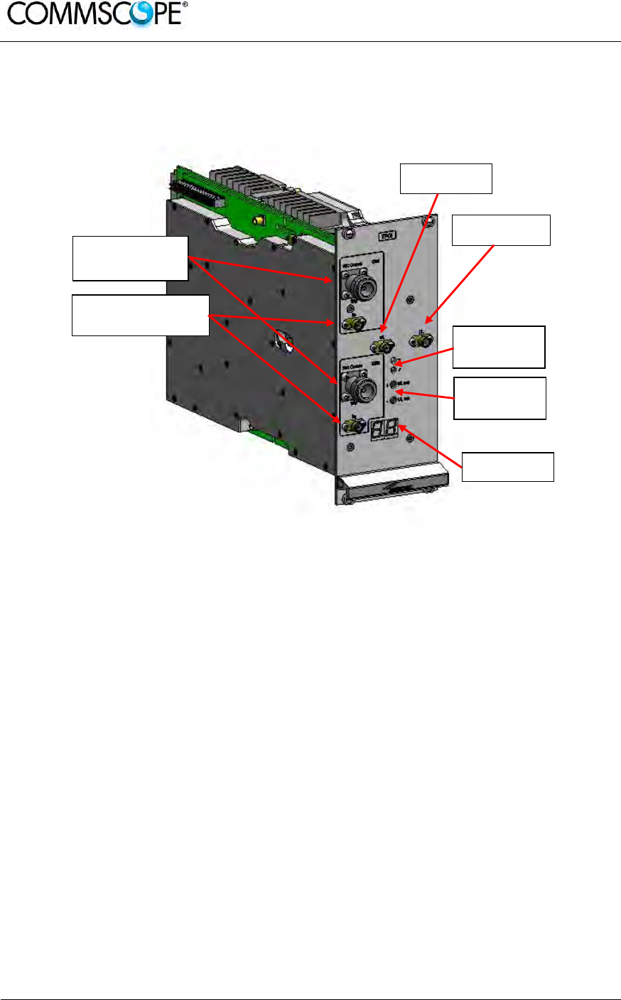
User’s Manual for ION-B Systems
Page 188 ION-B User Manual (MN024-15)_n_20150730.docx
6.9.2. TPOI MIMO
6.9.2.1. Description
Figure 6-45 TPOI point of interface
The TPOI MIMO is an integrated point of interface which enables MIMO applications.
TPOI MIMO includes duplexer, digital adjustable attenuator, downlink automatic level
control (ALC) and cross band coupler functionalities which allows to feed the MIMO
booster through the master optical TRX with MIMO signals.
6.9.2.2. RF Ports
• 2 TRX RF ports, one for each channel
• 2 RX RF ports, one for each channel
• 1 DL RF output port
• 1 UL RF input port
Band specific
RX RF
p
orts
Band specific
TRX RF ports
DL RF port
UL RF port
Status and
Alarm LEDs
Setting
Buttons
Display

User’s Manual for ION-B Systems
ION-B User Manual (MN024-
15)_n_20150730.docx Page 189
6.9.2.3. Setting Buttons and Display
TPOI MIMO is provided with two setting buttons which can be used to set attenuation
manually through the following steps:
1. Press DL or UL button according to the attenuation you want to set. Current
value is displayed in the display.
2. Press again the button to start setting procedure: the value on the display start
blinking
3. Use DL button to increase attenuation value and UL button to decrease it
4. Hold again the initial button for more then 3 sec. to have the value stored.
Alternatively attenuation can be set through LMT or supervision system
6.9.2.4. TPOI MIMO Visual alarms
The TPOI front panel is provided with 2 LEDs showing status and alarm information.
LED significance is reported in the table below.
Label LED
colour Significance
= Green Power supply status OK
Red General TPOI failure
table 6-17 LED alerts on the TPOI MIMO front panel
Further information about alarm status is delivered by the ION-B Supervision System.
6.9.2.5. TPOI Power Supply
Each TPOI MIMO is supplied by the subrack backplane (12V).
6.9.2.6. TPOI Insertion Loss
When designing the system, remember to take into account the insertion losses of
the TPOI, check the values on relevant bulletin.
6.9.2.7. Warnings
The overall DL input power must not exceed +33dBm.
6.9.2.8. Inserting or removing TPOI modules
• Do not remove or insert any TPOI module into TPRN subrack before having
switched off main power supply.
• The TPOI modules must be handled with care, in order to avoid damage to
electrostatic sensitive devices.
• When installing TPOI modules in the subrack, take care to alternate active and
passive cards in order to ensure proper heat dissipation.

User’s Manual for ION-B Systems
Page 190 ION-B User Manual (MN024-15)_n_20150730.docx
• In a multi-subrack system, remember to assign to each subrack a proper
RS485 bus address before installing the modules (please refer to Rack-Based
Master Unit section for further details).
6.9.2.9. TPOI MIMO Installation
The TPOI can be accommodated in any active TPRN subrack slot. It is 14TE wide
and 4HE high so it occupies two slots
Note: In case a new TPOI module has to be installed in a still working
Master Unit, switch off the subrack before inserting the plug-in TPOI
module.
Firstly, gently insert the TPOI into any of available slots, and lock the 4 screws on the
front corners.
Then, connect the system input signals to the TRX ports and if needed to the RX
ports (remove SMA loads before connecting) making sure to connect to the right
channel section.
Connect the UL and DL RF cable to the next board UL and DL ports, respectively.
Use an appropriate torque wrench to fix these RF cables.
As you switch on the system, make sure to set properly the attenuation (see Setting
Buttons and Display section). The provided reading of the output power through the
LMT or supervision system can help in setting up the system.
Remember that Remote Units should be switched on before the Master Unit in order
to follow the correct Start-Up procedure.
Label LED colour Status
= Green
ON
(power supply is on)
Red OFF
(no major failure affects TPOI operations)
table 6-18 LED alerts on the TPOI front panel
6.9.2.10. TPOI Troubleshooting
In case a TPOI has any problems, this will be easily revealed through the LEDs on its
front panel, otherwise troubleshooting can be carried out through the LMT or the
Supervision system.ù
The below table reports a brief description of the TPOI alarms, together with a
reference to the corresponding alerted LEDs.
As the table shows, LEDs on the TPOI front panel signal all high priority alarms while
minor alarms, which detect critical situations which should be checked and tested in
order to avoid future possible system faults, are only revealed by the LMR or the
Supervision System.

User’s Manual for ION-B Systems
ION-B User Manual (MN024-
15)_n_20150730.docx Page 191
Alarm Code
(TSUN
description) Alarm description Active
LED
Supervision
Priority
Level
Action
Recommended
Relé
Priority
Level
Over Power
RF input power
exceeds the
absolute maximum
composite input
power
RED MAJOR Reduce input
power MAJOR
Overdrive/ALC
Limiting
RF output power
exceeds the
defined Overdrive
Threshold
NONE MINOR Reduce input
power MINOR
UL MIMO Ch.1
RF alarm
UL Ch.1 RF stage
malfunctioning or
syncronization
missing
RED CRITICAL
Check RF
cables. If ok, try
rebooting the
unit, if no
changes return
the unit
MAJOR
UL MIMO Ch.2
RF alarm
UL Ch.2 RF stage
malfunctioning or
syncronization
missing
RED CRITICAL
Check RF
cables. If ok, try
rebooting the
unit, if no
changes return
the unit
MAJOR
DL MIMO Ch.1
RF alarm
DL Ch.1 RF stage
malfunctioning or
syncronization
missing
RED CRITICAL
Check RF
cables. If ok, try
rebooting the
unit, if no
changes return
the unit
MAJOR
DL MIMO Ch.2
RF alarm
DL Ch.2 RF stage
malfunctioning or
syncronization
missing
RED CRITICAL
Check RF
cables. If ok, try
rebooting the
unit, if no
changes return
the unit
MAJOR
Vcc alarm Internal power
supply
malfunctioning RED MJOR Return the unit MAJOR
Power Supply
alarm Subrack power
supply failure RED MAJOR
Check power
supply provided
by the subrack
and in case
replace it
MAJOR
Temperature
alarm Over-temperature
alarm NONE WARNING
Check ventilation
and environment MINOR
table 6-19 LED alerts on the TPOI front panel
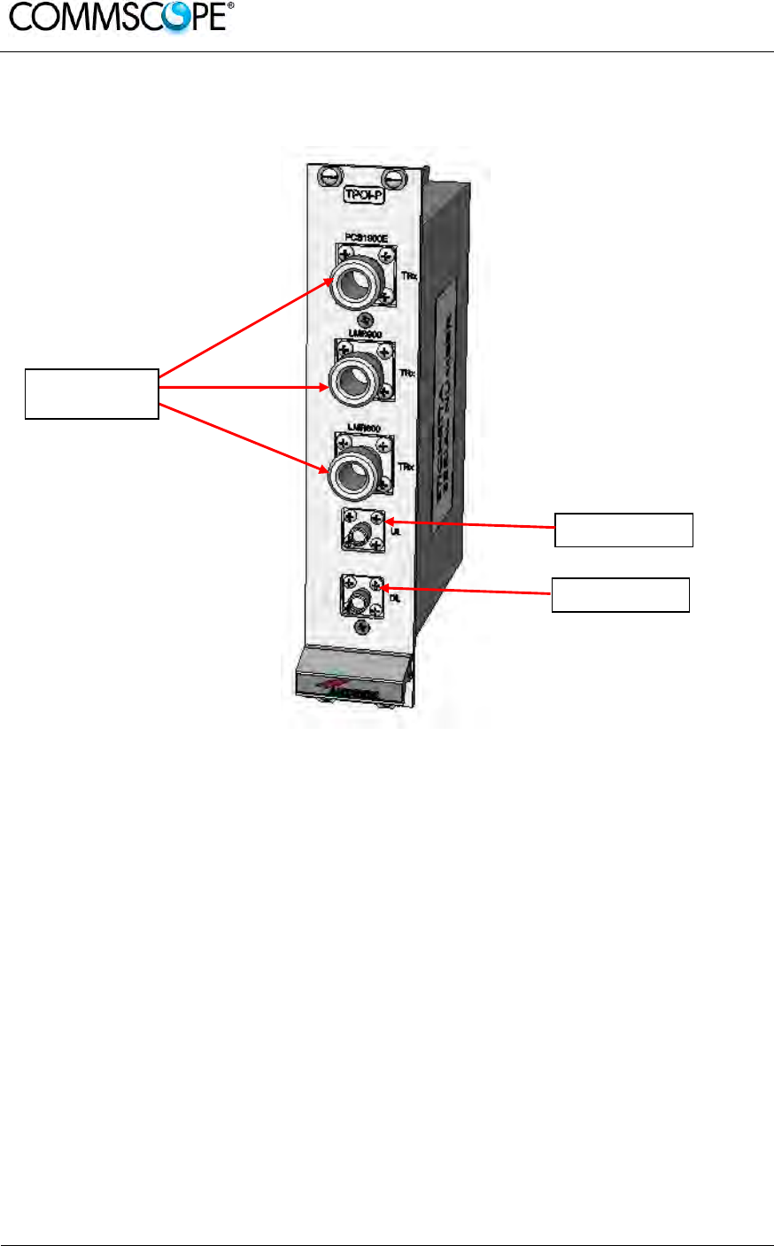
User’s Manual for ION-B Systems
Page 192 ION-B User Manual (MN024-15)_n_20150730.docx
6.10. PASSIVE MULTIBAND POINT OF INTERFACE TPOI-P
6.10.1. Description
Figure 6-46 TPOI-P passive point of interface
The TPOI-P is an integrated passive multiband point of interface which enables triple
band, applications. Different configurations are available answering to the possible
band combinations.
TPOI-P includes duplexer and cross band coupler functionalities which allows to feed
the master optical TRX
6.10.2. TPOI-P Models
The POI-P is available in different versions, depending on the band it addresses. For
a list of the TPOI-P models currently available check relevant bulletin.
6.10.3. RF Ports
• 3 TRX RF ports, one for each band
• 1 DL RF output port
• 1 UL RF input port
Band specific
TRX RF
p
orts
UL RF port
DL RF port

User’s Manual for ION-B Systems
ION-B User Manual (MN024-
15)_n_20150730.docx Page 193
6.10.4. TPOI-P Main Applications
TPOI-P module is used to interface with duplexed signals coming from different
donor sources and combine them into RF connectors to drive the TFLN master
optical TRX.
6.10.5. TPOI-P Insertion Loss
When designing the system, remember to take into account the insertion losses of
the TPOI-P, check the values on relevant bulletin.
6.10.6. Warnings
The overall input power must not exceed +33dBm.
6.10.7. TPOI-P Installation
Since the TPOI-P module does not require any power supply, it can be housed either
in an active or a passive TPRN subrack.
1. Unpack the kit which includes: 1 TPOI-P
2 RF jumpers (SMA-m), 2 x 35cm
2. Carefully insert the TPOI-P module into any of the TPRN subrack slots and
tighten the four screws on the front corners.
3. Connect RF cables according to what has been planned by the designer. Use
an appropriate wrench to fasten each cable to their relevant ports.
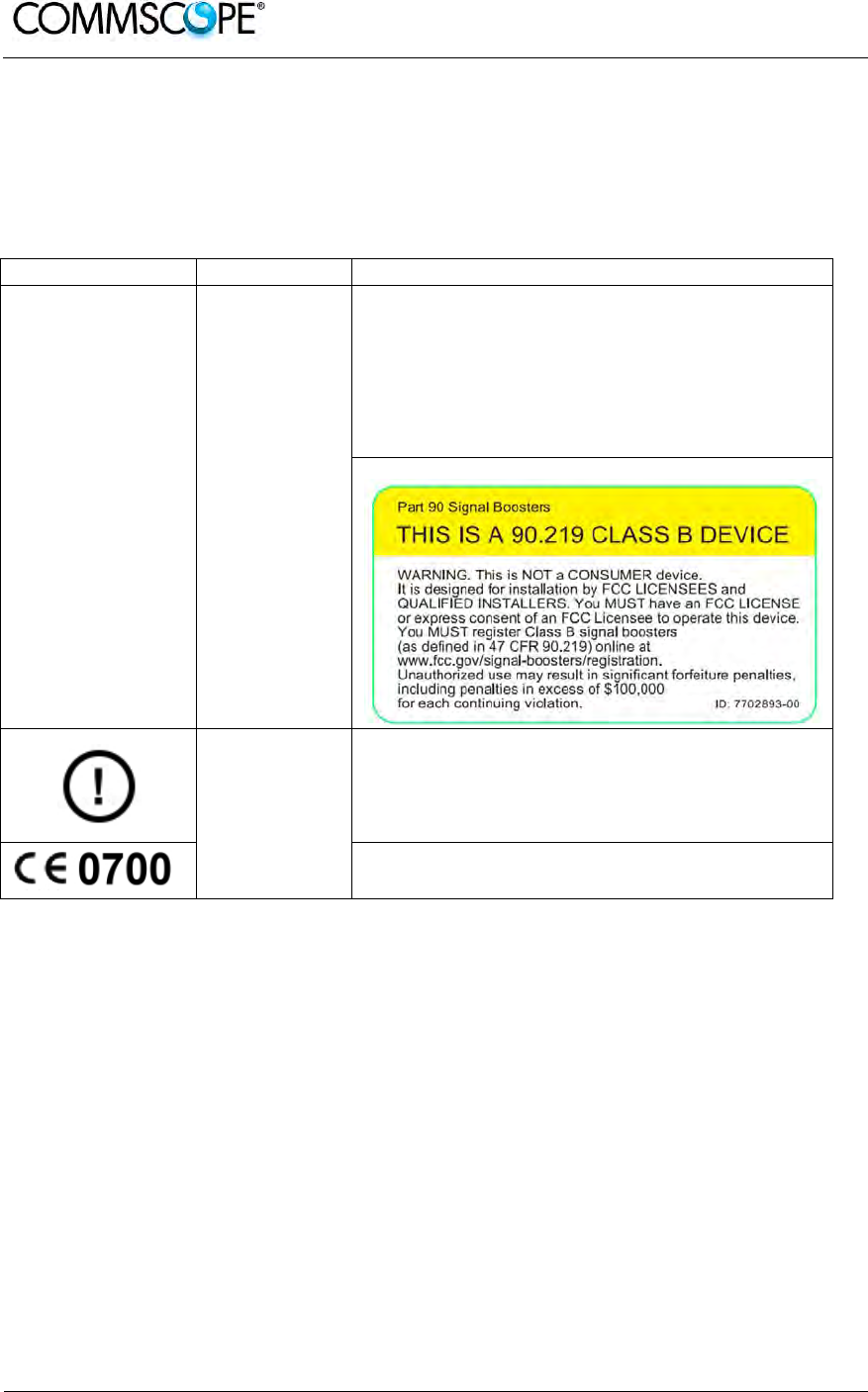
User’s Manual for ION-B Systems
Page 194 ION-B User Manual (MN024-15)_n_20150730.docx
7. WARNING AND SAFETY REQUIREMENTS
7.1. EQUIPMENT SYMBOLS USED / COMPLIANCE
Please observe the meanings of the following symbols used in our equipment and
the compliance warnings:
Symbol Compliance Meaning / Warning
--- FCC
For industrial (Part 20) signal booster:
WARNING: This is NOT a CONSUMER device. It is
designed for installation by FCC LICENSEES and
QUALIFIED INSTALLERS. You MUST have an FCC
LICENSE or express consent of an FCC Licensee to
operate this device. Unauthorized use may result in
significant forfeiture penalties, including penalties in
excess of $100,000 for each continuing violation.
For (Part 90) signal booster:
CE
Alert sign to R&TTE
To be sold exclusively to mobile operators or authorized
installers – no harmonized frequency bands, operation
requires license. Intended use: EU and EFTA countries
Indicates conformity with the R&TTE directive
1999/5/EC certified by the notified body no. 0700.
7.2. ENVIRONMENTAL CONDITIONS
This equipment is designed to be installed in indoor environments.
Operating temperature: +5 to +40°C
Do not install in corrosive atmosphere or in critical environmental conditions such as
hazardous classified areas. Hazardous locations are those areas where fire or
explosion hazards may exist due to flammable gases or vapours, flammable liquids,
combustible dust, or ignitable fibres or flyings.
7.3. INSTALLATION SITE FEATURES
A trained technician should carry out the installation of the master unit. Since the
system is designed for indoor installation, the master unit should be installed in a dry
and suitable location where:

User’s Manual for ION-B Systems
ION-B User Manual (MN024-
15)_n_20150730.docx Page 195
there is no risk of explosion;
the environment is not classified as a high-risk one in case of fire;
suspended particles are not to be found in great concentration;
there is no risk of traffic which could cause
collision damages;
the site is properly located with respect to the ergonomic positioning of the
working environments;
the system is placed in a private room, protected against any possible
violation;
there is no direct sunlight or where water may drip on the device (for example
under air-conditioning equipment).
the site must be accessible by maintenance personnel;
the site must be dry, with low humidity;
the site must guarantee proper space for cables and natural ventilation for the
system;
2 meters must be kept between the rack and any heating opening.
The Remote Units should be mounted in reasonable locations as well:
Do not install Remote Units inside heating or conditioning areas;
Do not install Remote Units inside cable pipelines or fire-prevention sites (fire
escapes, lift tunnels, emergency exits; which have to guarantee defined safety
standards);
Please take into consideration that the temperature in the upper part of a room
is higher than at the 2 meter height. For false ceiling installation of Remote
Units, verify that the environment temperatures do not exceed allowed limits;
Each Remote Unit requires its own power and a connection to the mains might
be needed;
Take into consideration that each Remote Unit transmits an RF signal and the
safety volume must be respected (refer to country regulations for safety
volume magnitude);
Remote Units must be mounted according to installation instructions;
Weight and dimensions of Remote Units should be carefully considered when
choosing the installation site and positioning. During any installation step,
please consider the potential risk of any equipment falling or dropping
unexpectedly.
When choosing the installation site and position, please consider that all
Remote Units must be accessible for tests and maintenance.

User’s Manual for ION-B Systems
Page 196 ION-B User Manual (MN024-15)_n_20150730.docx
7.4. SAFETY AND PRECAUTIONS DURING INSTALLATION OR
MAINTENANCE
During installation, the following tools and equipment will be needed:
Typical electrician tools:
cross-point screwdriver, scissors, pliers, nippers, drill and bits, screws for fixing
Remote Units to the wall.
Typical equipment:
proper ladder, scaffolding or air platform for installation of Remote Units.
Attention: some modules are electrostatic-sensitive devices;
electrostatic discharges are caused by direct contact or by an electrostatic
field. If a charged body approaches an electrically conducting surface, the
acquired potential is discharged. An equalising current can than flow in the
associated circuitry and generate permanently damaging voltages by
induction.
Note: The human body should be grounded at the same potential as the
component or equipment being handled. A wrist strap creates an
equipotential electrical connection between the object and the
human.
Attention: Do not paint or otherwise coat ION-B equipment.
Attention: Great caution should always be used when installing any
equipment at a height higher than 2 meters. Personnel who are installing
this equipment should be informed about the possible risks and safety
measures when elevated.
Never remove the cover from a TFAx Remote Unit or from a TPRN
subrack when the power supply is ON.

User’s Manual for ION-B Systems
ION-B User Manual (MN024-
15)_n_20150730.docx Page 197
7.5. POWER SUPPLY CONNECTION
Power connection must be carried out following all necessary precautions:
It must be properly made according to due diligence rules (e.g. EN rules, IEC rules,
etc.);
in accordance with the rules for safety against direct or indirect contacts;
in accordance with the rules for safety against over current (short circuit, overloading)
in accordance with the rules for safety against over voltage;
connection is to be carried out by appropriate and competent staff
Note: In North America, this equipment is to be installed in accordance
with the National Electric Code (NEC) ANSI/NFPA 70 and the
Canadian Electric Code (CEC) Part 1, C22.1.
Attention
: Do not remove or insert any module into the TPRN sub-rack without
prior switching the power supply OFF.
Attention
Do not connect the AC power until you have verified that the line voltage is correct.
Do not remove the plastic cover of the external power supply adapter.

User’s Manual for ION-B Systems
Page 198 ION-B User Manual (MN024-15)_n_20150730.docx
7.6. SAFETY AND LASER PRECAUTIONS
The optical transmitter used in the ION-B contains a laser which has a power level
that is not dangerous for health. However it is classified as class 1 equipment (in
accordance with EN60825). It is nevertheless prudent, during the installation phase,
to observe the following rules:
Never look directly inside the optic connector exit of the transmitter when it is
switched on. The wavelength of the laser is not visible to the human eye,
which means that long-term damage will not be immediately known.
When working with the optical connectors, check at each end that both
transmitting lasers are switched off.
7.7. HEALTH AND SAFETY
Please be aware that each country or governmental body has established its own
specific limits for RF exposure, to which the installation of any radiating antenna must
conform. When installing your ION-B system, take care to comply to your local
regulations and guidelines about RF exposure limits.
Antenna installation must conform to the following guidelines to meet FCC and RSS
RF exposure limits, otherwise an environmental evaluation is required.
RSS Canadian standards
To meet RSS Canadian standard the following guidelines have to be taken into
account:
For any situation where multiple carrier signals are present, take care to
reduce the single-carrier output rating at least by 3.5dB, especially when the
output signal is reradiated and can cause interference with adjacent band
users. This power reduction can be achieved by reducing the input power
which enters the TFLN input ports, not through an attenuator at the output of
the ION-B devices.
FCC US standards
To meet FCC US standard the following guidelines have to be taken into account:
To comply with the FCC exposure compliance requirements, the following
antenna installation and device operating conditions must be satisfied: The
antenna(s) used in the system must be installed to maintain at least a 50-cm
separation distance from any person. The highest allowed antenna gain,
including coaxial cable loss, is 11dBi. RF exposure compliance may need to
be addressed at the time of licensing, as required by the responsible FCC
Bureaus(s), including antenna co-locating requirements of 1.1307(b)(3).
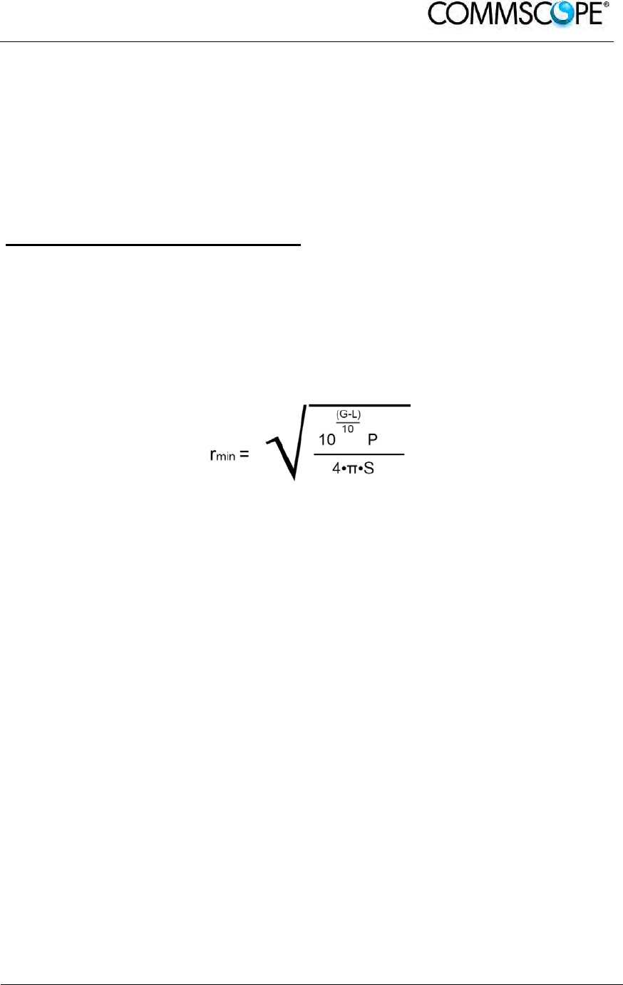
User’s Manual for ION-B Systems
ION-B User Manual (MN024-
15)_n_20150730.docx Page 199
7.8. ELECTROMAGNETIC FIELDS AND RF POWER
The ION-B system generates electromagnetic radiation, which can exceed safety
levels in the immediate vicinity of the antenna.
The most widely accepted standards are those developed by the International
Commission on Non-Ionizing Radiation Protection (ICNIRP) and the Institute of
Electrical and Electronics Engineers (IEEE).
Formula for minimum safety distances
The formula for calculating the minimum safety distances uses the specifications of a
particular antenna that could be driven by TFAx.
This equation includes the following factors:
G is the antenna gain (in dB) compared to isotropic radiating antennas;
P is the RF power that is present at the antenna connector (in W);
L is the total loss (in dB) between the TFAx Remote Unit output port and
the antenna input port;
S is the power density in air (in W/m2) maximum allowed. Its values should
be calculated according to the limit exposures to time-variations and
magnetic fields. The reference values are reported in the ICNIRP
guidelines, unless otherwise specified by specific regulations.
(Please note that, if regulations only define the maximum electrical and
magnetic field strengths, the allowed power density is able to be be obtained
by: S= E
2
/377= B
2
·377
where 377 is the characteristic’s impedance of the empty space).

User’s Manual for ION-B Systems
Page 200 ION-B User Manual (MN024-15)_n_20150730.docx
Example 1.
A Medium Power TFAM 18/20P must distribute mobile signals through a directional
antenna, fed by a 2-metre length RG223 cable (no splitters used). The antenna gain
is 7 dB and the ION-B system distributes one GSM 1800 MHz carrier and one UMTS
2100 MHz carrier.
The maximum allowed power density we have to comply with is:
S = 10 W m
-2
(typical ICNIRP reference level for general public exposure to time-varied electric and
magnetic fields).
By reading the relevant notes for the TFAM 18/20P Remote Unit, we know the overall
output power at the antenna port is able to be estimated as follows:
20 dBm ± 2 ( +22 dBm maximum, equivalent to 0.158 W) for the Cellular 850 MHz
band
20 dBm ± 1.5 ( +21.5 dBm maximum, equivalent to 0.141 W) in the PCS 1900
MHz band.
The total output power at the antenna port is therefore P = 0.158 + 0.141 = 0.299
W.
By reading the cable specs, we get that RG223 cable losses can be estimated at
0.55 dB/m. Total losses between the TFAM 18/20P output port and the antenna input
port can therefore be estimated as follows:
L = 0.55 (dB/m) x 2 (m) = 1.1 dB
By replacing the above values of G, L, P, S parameters inside the formula 6.1, we
therefore get the the following minimum safety distance from the antenna:
r
min
= { 10 -· exp [ (7 - 1.1) / 10 ] · 0.299} / (4·π·10) } - exp (1/2) = 0.096 m
Example 2:
A Low Power TFAH85/19 through a directional antenna is used, fed by a 20 -metre
length ½” cable, with a 2-way splitter. The antenna Gain is 7 dB and the ION-B
system distributes one Cellular 850 MHz carrier and one PCS 1900 MHz carrier.
The maximum allowed power density we have to comply with is:
S = 50 W·m2
(typical ICNIRP reference level for occupational exposure to time-varied electric and
magnetic fields)

User’s Manual for ION-B Systems
ION-B User Manual (MN024-
15)_n_20150730.docx Page 201
By reading the ION-B notes, we know that the output power per carrier at the TFAM
antenna port is
30 dBm ± 2 ( +32 dBm maximum, equivalent to 1.202 W) for the Cellular 850 MHz
band
30 dBm ± 2 ( +32 dBm maximum, equivalent to 1.202 W) for the PCS 1900 MHz
band
The ½” cable losses are 0.07 dB/ m in the 900 MHz band, and 0.11 dB/m in the 2100
MHz band.
The splitter insertion losses are 3.5 dB. The total losses between the TFAH85/19
output port and the antenna input ports can therefore be estimated as follows:
L
850MHz
= 0.07 (dB/m) x 20 (m) + 3.5 = 4.9 dB for Cellular 850 MHz signals
L
1900MHz
= 0.10 (dB/m) x 20 (m) + 3.5 = 5.5 dB for PCS 1900 MHz signals
The term “10 exp (G-L/10) P” which appears inside the formula 6.1 should therefore
be calculated seperately for each frequency, and then added in order to calculate the
composite contribution:
P
850MHz, ant
= 10 exp [(7-4.9)/10]· 1.202 = 1.949 W
P
1900MHz, ant
= 10 exp [(7-5.5)/10]· 1.202 = 1.698 W
P
composite
= P
850MHz, ant
+ P
1900MHz,ant
= 3.647 W
By dividing the total power through (4··S) and taking the square root according to the
formula 6.1, we therefore get the following minimum safety distances from the
antenna:
r
min
= { P
composite
/(4·π·50)} - exp (1/2) = 0.02 m
Example 3.
There is a Medium Power TFAM91/18/20 which is connected to an omnidirectional
antenna through a 10-metre length RG223 cable (no splitters used). The antenna
Gain is 7 dB and the ION-B system distributes two GSM900 carriers, two
GSM1800carriers, and one UMTS2100 carrier.
The maximum allowed electrical field strength is:
E = 6 V m
(typical Italian reference level for exposure to time-varied electric and magnetic
fields). The corresponding value of the maximum allowed power density is:
S = E
2
/377 = 0.1 W/m
2
User’s Manual for ION-B Systems
Page 202 ION-B User Manual (MN024-15)_n_20150730.docx
By reading the relevant notes for the TFAM 91/18/20 Remote Unit, the overall output
power at the TFAM antenna port can be estimated as follows:
20 dBm ± 2 (+22 dBm maximum, equivalent to 0.158 W) for the Cellular 910 MHz:
21 dBm ± 2 ( +23 dBm maximum, equivalent to 0.200 W) for the GSM1800)
26 dBm ± 1 ( +27 dBm maximum, equivalent to 0.501 W) in the UMTS band
The total output power at the antenna port is therefore:
P = 0.158W x 2 + 0.200W + 0.501W = 1.345 W,
By reading the cable specs, we get that RG223 cable losses can be estimated at
0.55 dB/m. Total losses between the TFAM 91/18/20 output port and the antenna
input port can therefore be estimated as follows:
L = 0.55 (dB/m) x 10 (m) = 5.5 dB
By replacing the above values of G, L, P, S parameters inside the formula 6.1, we
therefore get the the following minimum safety distance from the antenna:
r
min
= { 10 - exp [ (7 - 5.5) / 10 ] - 1.345} / (4··0.1) } - exp (1/2) = 1.22 m
7.9. WARNING LABELS
CLASS 1 laser product
GROUND - Use this terminal for a safety
ground connection for the equipment.

User’s Manual for ION-B Systems
ION-B User Manual (MN024-
15)_n_20150730.docx Page 203
8. TECHNICAL SUPPORT
8.1. CONTACT ADDRESSES
The ION-B is developed by:
Commscope Italy Srl
Via Pier De Crescenzi 40
48018 Faenza, Italy
Tel: +39.0546.697111
Fax: +39.0546.682768
8.2. DCCS TECHNICAL SUPPORT
For technical assistance and support, please contact the DCCS technical support team.
Email: wisupport@commscope.com
+1 888-297-6433 in North and South America and +49 9099-69-333 in Europe, Middle East and Asia

User’s Manual for ION-B Systems
Page 204 ION-B User Manual (MN024-15)_n_20150730.docx
8.3. RETURNING EQUIPMENT
Before returning any equipment to the manufacturer for repairation or replacement, the
customer should give prior notice to the manufacturer and ask for the ‘Return Material
Authorisation’ (RMA request).
RMA REQUEST FORM
Company name
Address
Contact person
Invoice number
Delivery note
№ of pieces
Model 1)
Serial Number 1)
Lot1)
Year1)
Description of the failure/ defect
1) Please refer to the serial label
Upon accepting your RMA request, the manufacturer will assign you a unique RMA
code. You will therefore be able to return the equipment to the manufacturer. Please
remember that:
each piece of equipment must be packaged with care before shipment;
a copy of the RMA request form must be included with the returning
equipment, with clear indication of the RMA code you received from the
manufacturer.
The returned pieces are able to be repaired (where possible) or replaced (when no
repairations can be carried out). These operations are performed under warranty
(please see the warranty conditions specified in the sales contract) or out-of-
warranty. In the latter case, we will send you a bill for equipment repairation or
replacement.
When returning the repaired or replaced equipment, the manufacturer will issue a
check report, which will be included in the packaging together with the returned
pieces. The customer will be informed of any corrective actions suggested for quality
assurance.
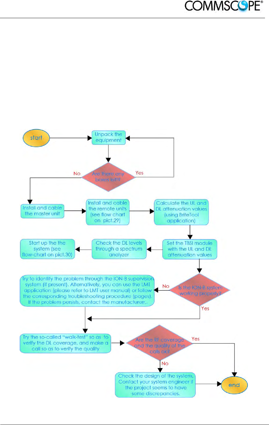
User’s Manual for ION-B Systems
ION-B User Manual (MN024-
15)_n_20150730.docx Page 205
9. APPENDIXES
9.1. APPENDIX A: SYSTEM COMMISSIONING
The following flow charts are a quick reference for the ION-B
®
system installation and
commissioning.
The first flow chart (Figure 9-1 Flow-chart describing the main installation and
commissioning steps) highlights the main steps for system installation and
commissioning starting from the equipment unpacking up to the check of the
coverage and call quality.
Figure 9-1 Flow-chart describing the main installation and commissioning steps
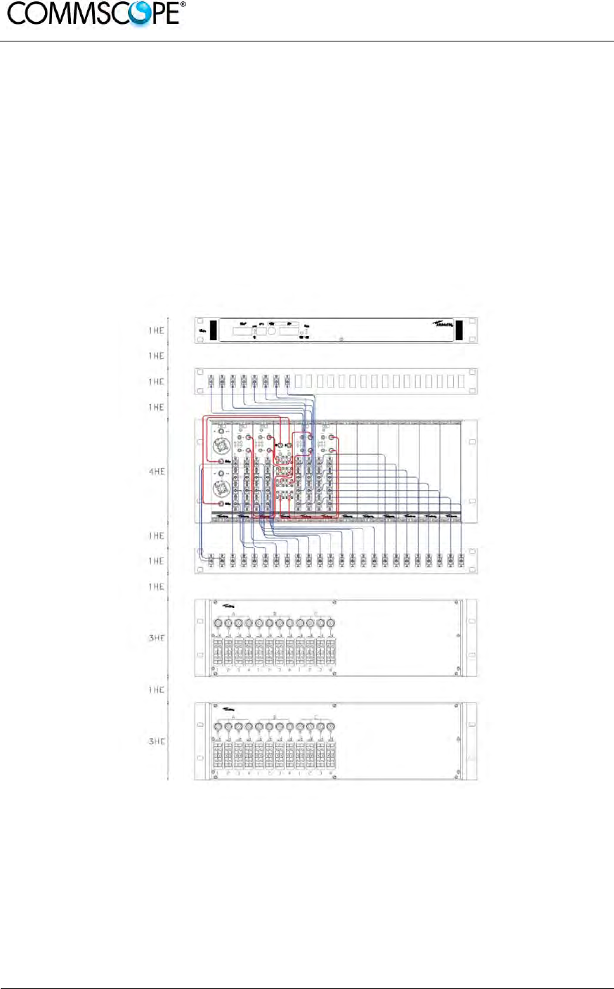
User’s Manual for ION-B Systems
Page 206 ION-B User Manual (MN024-15)_n_20150730.docx
The previous flow chart contains the following cross references:
• the master unit installation and cabling is described in more detail in the flow
chart (Figure 9-3 Flow-chart describing the Master unit installation and cabling
steps). It follows the flow of actions from the subrack mounting on the cabinet up
to the settings and connections needed in case remote supervision has to be
considered.
An example of system layout at master unit side is presented in figure below for
a configuration consisting in one sector with four TFLN master optical Trxs.
For more details about TSUNx configuration and start-up refer to the Remote
Supervision manual.
Figure 9-2 Case layout for a 1 sector with 4 TFLN master optical transceivers
• once the whole system has been installed, the attenuation on the base station
interface has to be defined in order to set up the performances. Use the Britetool
Software to calculate the required attenuation values for uplink and downlink.
Refer to the Britetool manual for more information.
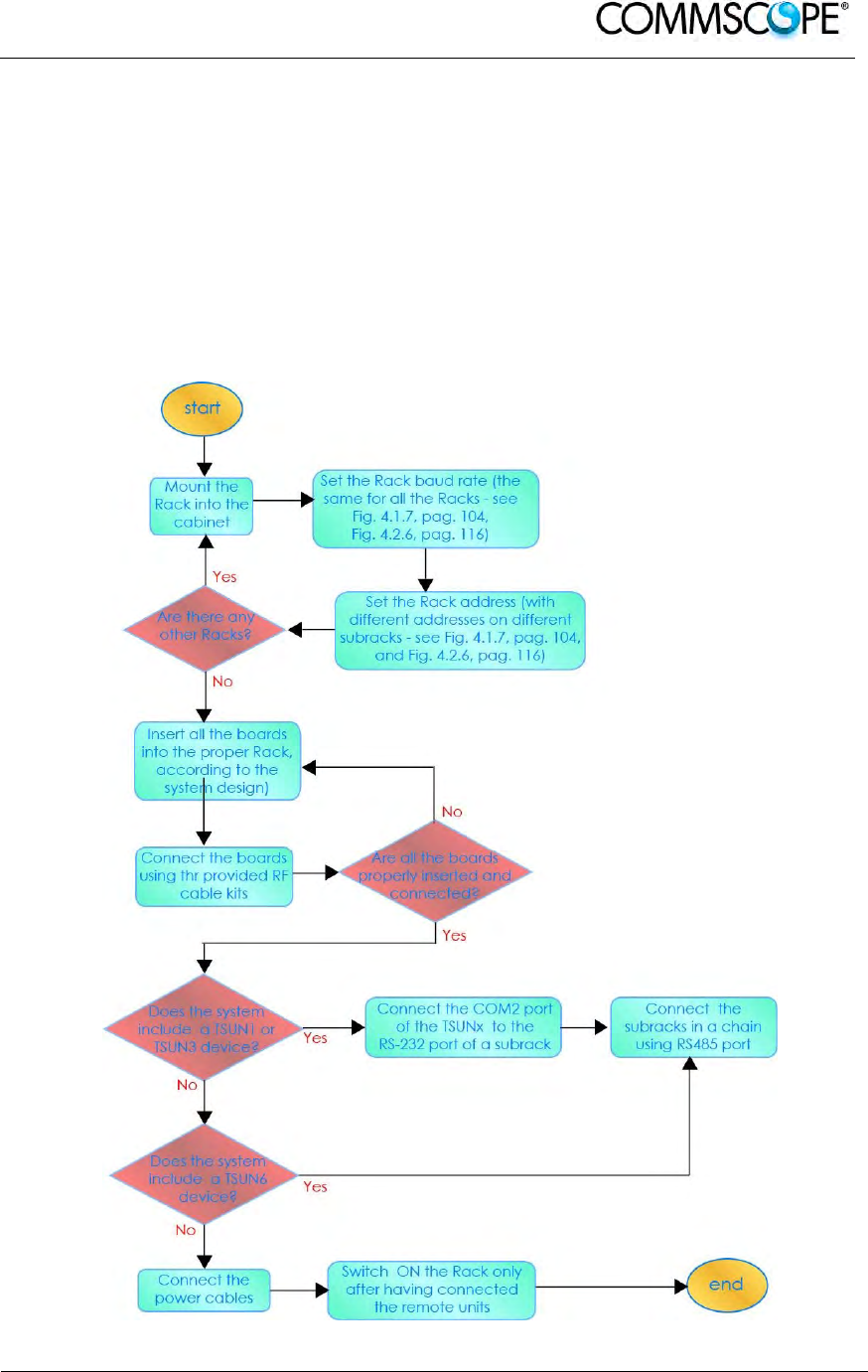
User’s Manual for ION-B Systems
ION-B User Manual (MN024-
15)_n_20150730.docx Page 207
• the system start-up is described in more detail in the flow chart (Figure 9-4 Flow-
chart describing the system start-up steps). It follows the flow of actions from the
remote and master unit switch on and discovery up to the system configuration
through LMT Software and/or remote supervision system.
For more details on how to use the LMT and about TSUNx configuration and
start-up refer to their relevant manuals.
• in case the system is not working properly, refer to the troubleshooting
procedures reported in their relevant sections.
Figure 9-3 Flow-chart describing the Master unit installation and cabling steps
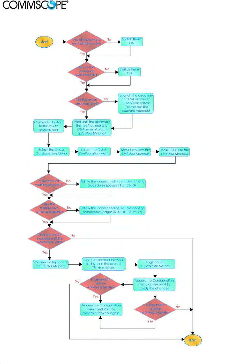
User’s Manual for ION-B Systems
Page 208 ION-B User Manual (MN024-15)_n_20150730.docx
Figure 9-4 Flow-chart describing the system start-up steps