Andrew EOCELL24RMT EOCell Transceiver System User Manual 2400 MHz EOCell FO DAS Rev L
Andrew Corporation EOCell Transceiver System 2400 MHz EOCell FO DAS Rev L
UserManual.wiki
>
Andrew
>
EOCELL24RMT User Manual
user manual
Navigation menu
Upload a User Manual
Namespaces
Wiki Guide
HTML
PDF
Info
Views
User Manual
Discussion / Help
Navigation


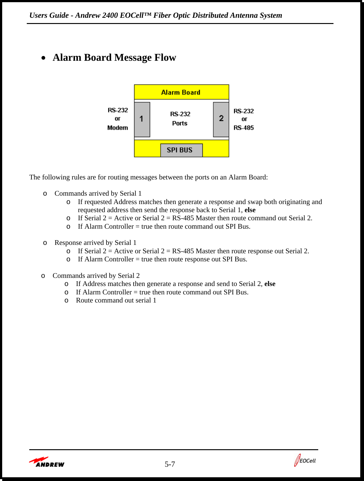
![Users Guide - Andrew 2400 EOCell™ Fiber Optic Distributed Antenna System 5-9 • System Level Message Flow NMS ComputerAlarm BoardTransceivers FiberOpticsRS-232Port 1SPIBusLocal11,11,2RemoteTransceivers1,20FiberOptics Alarm Board (1) is configured as an Alarm Controllers Normal Operations Rules: o Alarm board (1) polls the local transceivers [(1,1) (1,2)] on the SPI Bus and maintains their status. o Alarm board (1) also polls the remote transceivers [(1,10)(1,20)] and maintains their status.](https://usermanual.wiki/Andrew/EOCELL24RMT/User-Guide-899579-Page-43.png)
![Users Guide - Andrew 2400 EOCell™ Fiber Optic Distributed Antenna System 5-10 • 16-Bit Check Sum algorithm //Table to match NMS calculation #define TABLE_SIZE 16 static const unsigned short uiCRCTable[TABLE_SIZE]= { 0x0000,0x1081,0x2102,0x3183,0x4204,0x5285,0x6306,0x7387, 0x8408,0x9489,0xA50A,0xB58B,0xC60C,0xD68D,0xE70E,0xF78F }; #define SHIFT_COUNT 4 unsigned int CRC_16(unsigned char *stringpointer, unsigned char stringlength) { int nIndex; unsigned char ucData; unsigned int uiCRCValue; uint8 *pData; int i;](https://usermanual.wiki/Andrew/EOCELL24RMT/User-Guide-899579-Page-44.png)
![Users Guide - Andrew 2400 EOCell™ Fiber Optic Distributed Antenna System 5-11 // initialize to seed value uiCRCValue = 0xffff; pData = stringpointer; //length is data bytes + address(2) + messageid(1) + data count(1) for(i = 0; i < stringlength; ++i) { /* get the data byte */ ucData = *pData; pData++; /* get index into uiCRCTable using least significant nibble of data byte */ nIndex = (uiCRCValue ^ ucData) & 0x0F; /* calculate new uiCRCValue using table value */ uiCRCValue = ((uiCRCValue >> SHIFT_COUNT) ^ uiCRCTable[nIndex]); /* get index into uiCRCTable using most significant nibble of data byte */ nIndex = (uiCRCValue ^ (ucData >> SHIFT_COUNT)) & 0x0F; /* calculate new uiCRCValue using table value */ uiCRCValue = ((uiCRCValue >> SHIFT_COUNT) ^ uiCRCTable[nIndex]); } return uiCRCValue; }](https://usermanual.wiki/Andrew/EOCELL24RMT/User-Guide-899579-Page-45.png)
![Users Guide - Andrew 2400 EOCell™ Fiber Optic Distributed Antenna System 5-14 Get Alarm Board Detail Status this command retrieves the detail status of the Alarm Board, located in the Master Rack. Alarms monitored on the Alarm Board are: Power Supply (#1, #2) Present DC FARM Module [of either Power Supply 1 or Power Supply 2 or both, if both are installed] AC/DC Converter Module [of either Power Supply 1 or Power Supply 2 or both, if both are installed] • Get Detail Status Command (0x92) Command: 0x92 Data: None • Get Detail Status Response (0x12) Response: 0x12 Byte count: 35 Data: (see table below) Items Byte No. Bit Definition Description Temperature Status 1 1 –7 Not used. 8 0 = within –25 to +65°C, 1 = outside temperature range Not Applicable 2 –6 1 0 = Power Supply #1 Present 1 = Module not present 2 0 = Power Supply #2 Present 1 = Module not present 7 3 – 8 Not used. 1 0 = PS#1: AC/DC Converter okay 1 = Module fail 2 0 = PS#1: DC/DC Regulator okay 1 = Module fail 3 0 = PS#2: AC/DC Converter okay 1 = Module fail 4 0 = PS#2: DC/DC Regulator okay 1 = Module fail Power Supply Status 8 5 – 8 Not used. Not Applicable 9 – 35](https://usermanual.wiki/Andrew/EOCELL24RMT/User-Guide-899579-Page-48.png)