Andrew EOCELL24RMT EOCell Transceiver System User Manual 2400 MHz EOCell FO DAS Rev L
Andrew Corporation EOCell Transceiver System 2400 MHz EOCell FO DAS Rev L
Andrew >
user manual

2
24
40
00
0
M
MH
Hz
z
E
EO
OC
Ce
el
ll
l
T
Tr
ra
an
ns
sc
ce
ei
iv
ve
er
r
S
Sy
ys
st
te
em
m
Installation and Users Guide
Copyright Andrew Corporation
February 2008

ii
Proprietary Information
This document is the property of Andrew Corporation. The information contained herein is
proprietary to Andrew, and no part of this document may be reproduced or transmitted in any
form or by any means, electronic or mechanical, for any purpose, without the express written
permission of Andrew.
Disclaimer
Andrew reserves the right to make changes, without notice, to the specifications and materials
contained herein. While we have worked diligently to insure every element presented is correct,
we shall not be responsible for errors. For the latest product information and technical
specifications, please see the contact information below.
© Copyright Andrew Corporation, February 2008, Printed in USA, All rights reserved.
FCC Notice
This equipment complies with Part 15 of the FCC rules. Any changes or modifications not
expressly approved by the manufacturer could void the user’s authority to operate the equipment.
Warnings
All persons must be 30 cm or more from the system antennas to comply with FCC rules for RF
exposure from spread spectrum transmitters in the 2400 MHz band.
This device has been designed to operate with an antenna having a maximum gain of 12 dB.
Antenna having a higher gain is strictly prohibited per regulations of Industry Canada. The
required antenna impedance is 50 ohms.
To reduce potential radio interference to other users, the antenna type and its gain should be so
chosen that the equivalent isotropic radiated power (EIRP) is not more than that required for
successful communication.
Trademarks
EOCell™ is a trademark of Andrew Corporation. All other trademarks belong to their respective
owner.

iii
Contact Information
For more information about Andrew’s capabilities to extend RF signals coverage into structures,
including office buildings, shopping complexes, warehouses, tunnels, and mines, please contact
us using the information below:
Andrew Corporation
Distributed Communications Systems
2601 Telecom Parkway
Richardson, Texas 75082
Attention: Mr. Matthew Thomas
E-mail:matthew.thomas@andrew.com
Fax: (972) 952-0018
Voice: (972) 952-9700
Andrew Corporation
Andrew Corporation is a global designer, manufacturer, and supplier of communications
equipment, services, and systems. Andrew products and expertise are found in communications
systems throughout the world; including wireless and distributed communications, land mobile
radio, cellular and personal communications, broadcast, radar, and navigation. The Andrew
"Flash" trademark seen on the cover can also be seen in every corner of the world on broadcast
towers and microwave antennas, HELIAX® and RADIAX® cables, communications and
computer networking equipment. The mark of Andrew for more than 60 years, it is the
benchmark of quality wherever it appears. It is a symbol of commitment to customer satisfaction
from the 4,500-plus employees of Andrew Corporation. We are listed on the NASDAQ stock
exchange under symbol “ANDW.” To learn more about us, please visit our web site at
www.andrew.com.
Andrew In-Building Wireless Experience
The Andrew Corporation Wireless Innovations Group (WIG) has over 15 years experience
designing, installing, and managing large complex RF distribution systems for metropolitan
railways, building owners, and public mobile radio and telephone operators throughout the
world. For clients who do not need turnkey solutions, we offer product sales or product sales
with engineering support services.
Andrew offers a range of products to meet requirements of the in-building market. In the early
1980’s Andrew developed leaky cables as an adjunct to our coaxial cable business. This product
quickly led us to pursuing and executing wireless RF coverage in confined spaces such as
metros, road tunnels, and buildings. Through these projects, our Distributed Communications
Systems division acquired critical experience in project management and RF engineering of
these systems.

iv
Section 1: 2400 MHz EOCell™ Transceiver System Description ......................................... 1-1
Section 2: 2400 MHz EOCell™ Transceiver System Equipment Description..................... 2-1
Section 3: 2400 MHz EOCell™ System Cabling..................................................................... 3-1
Section 4: Implementations Using the Andrew EOCell™ System........................................ 4-1
Section 5: EOCell™ Network Monitoring Capabilities.........................................................5-1
Section 6: Fiber Optic Cable Installation Guide..................................................................... 6-1

1-1
Section 1: 2400 MHz EOCell™ Transceiver System Description
2400 MHz EOCell™ Transceiver System Page 1-2
2400 MHz EOCell™ Transceiver Electrical System Specifications Page 1-3
2400 MHz EOCell™ Transceiver System Mechanical/Environmental
Specifications Page 1-5
2400 MHz EOCell™ Transceiver System Theory of Operation Page 1-6
Downlink Signal Flow Page 1-7
Uplink Signal Flow Page 1-7

1-2
• 2400 MHz EOCell™ Transceiver System
The Andrew 2400 MHz EOCell™ Transceiver System is an RF to Fiber system for
Bombardier’s second generation ATC Radio System. The 2400 MHz EOCell™ Transceiver
System interfaces directly with a BTS / radio and distributes the RF signals to a distributed
antenna system that provide improved downlink and uplink performance. The 2400 MHz
EOCell™ system uses multiple Remote Fiber Fed Amplifier Units (RFFAUs) located within the
building or tunnel to optimize communications with portables and mobile radios. Each RFFAU
is connected to a EOCell™ Master Rack by two single mode fiber optic cables that provide
downlink and uplink signals to and from the RFFAUs.
The Andrew 2400 MHz EOCell™ Transceiver System is used to provide a wireless RF network
infrastructure within buildings, high rises, shopping malls, airports, tunnels and other confined
structures where outside wireless signals do not penetrate or propagate well. The 2400 MHz
EOCell™ system allows portable and mobile radio users to use their radios in indoor areas that
previously could not communicate with the wireless communication system.
Key 2400 MHz EOCell™ features:
• The 2400 MHz EOCell™ Transceiver System operates with Bombardier second
generation ATC Radio System.
• High downlink output power and low uplink noise figure result in an indoor Distributed
Antenna System (DAS) with a large coverage area.
• Predictable performance reduces design and implementation time.
• Single mode fiber optic cable used for wide bandwidth and low loss.
• Supports spread spectrum modulation in the 2400 MHz frequency band.
• Easy to install, only 2 small cables required to each remote amplifier unit.
• Flexible installation, cabling and configuration for multiple applications.
• Direct optical modulation of laser diode, no frequency up and down conversion.
• Continuous system built-in-test function provides remote alarm and local indicators in
case of faults in the equipment or the fiber optic cables.
The 2400 MHz EOCell™ Transceiver System uses low-loss fiber optic cables to distribute the
wireless signal throughout the building/tunnel to multiple remote antennas. The single mode
fiber optic cables used in the 2400 MHz EOCell system ensures that each of the RFFAU has
predictable coverage area and RF performance, regardless of how far the remote antenna is from
the central RF hub. The basic 2400 MHz EOCell system consists of one Master Fiber Optic
Transceiver Chassis (MFOTC) that interfaces with up to eight (8) Remote Fiber Fed Amplifier
Units.
1-3
The 2400 MHz EOCell Transceiver System is designed to interface to the external wireless
infrastructure by directly interfacing to an indoor base station / base radio through a coax jumper.
The 2400 MHz EOCell Transceiver System converts the RF signals from the base station / base
radio and the portable and mobile radios into optical signals. The 2400 MHz EOCell
Transceiver System, uses low loss fiber optic cables to distribute the optical signals throughout
the required coverage area, and then converts the signals back to RF signals for radio
transmission.
The 2400 MHz EOCell Transceiver System is designed to cover large areas with a minimum
amount of hardware and cabling, reducing system cost, installation time and maintenance. The
2400 MHz EOCell Transceiver System can support 24 RFFAUs per base station / base radio.
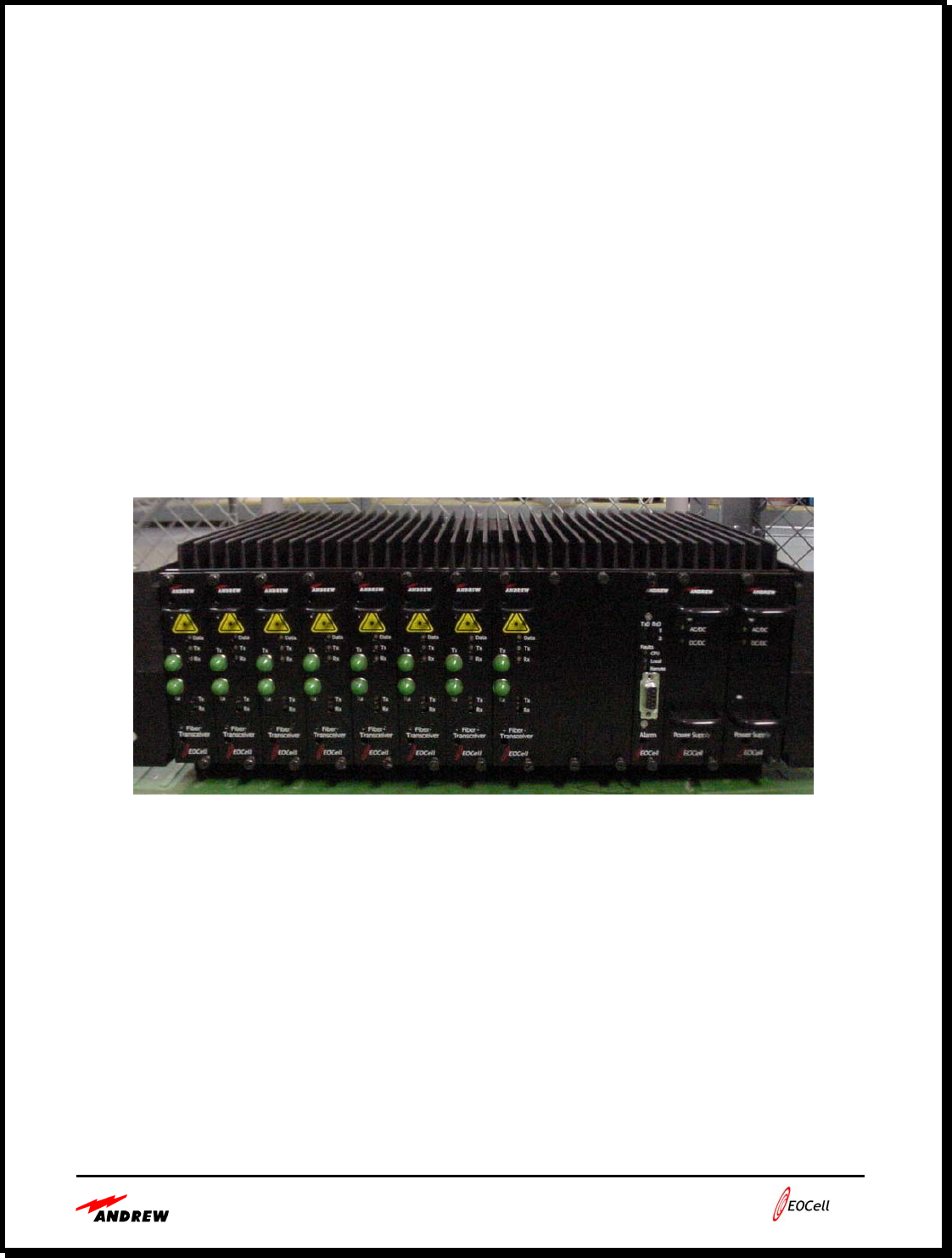
Figure 1-1 shows one 2400 MHz EOCell MFOTC that has 8 transceivers, an alarm board, and a
two (2) power supply modules. Only one power supply module is necessary, but a second can be
used for redundancy.
Figure 1-1. 2400 MHz EOCell™ MFOTC
The 385700-5000-001 to -004 systems consist of the Andrew EOCell Remote model number
385700-5000, the Andrew EOCell Master model number 385700-6000 and the Invensys Safetran
Spread Spectrum Radio model number ATC-24027 and Andrew RADIAX antenna p/n (s)
RCT6-S-1A-AX, RCT6-S-1A-RN, RCT6-S-1A-RNT1 or RCT6-S-1A-RNT. The electrical
characteristics are equal on all RADIAX antennas. The main difference between RADIAX types
is the fire rating. The system can also be used with a horn antenna up to 12dBi.

1-4
2400 MHz EOCell™ Transceiver Electrical System Specifications
PARAMETERS SPECIFICATIONS
Downlink Frequency Band 2440 – 2480 MHz
Uplink Frequency Band 2400 – 2440 MHz
Maximum number of remote cells per base
station / base radio 24
Maximum distance between Master and
Remote 20 km
Master Chassis Downlink (TX) Signal Level at
MFOTC TX input +5 dBm
Remote Downlink Signal Level Output
(maximum) * +27.5 dBm min (1-port model)
+24.0 dBm min (2-port model)
+22.5 dBm min (3-port model)
+20.5 dBm min (4-port model)
System Antenna Interface (remote) N-female connector. One-port model, Dual
port (internal 2-way power splitter), Three-port
(internal 3-way power splitter) and Four-port
(internal 4-way power splitter).
Diagnostic Alarms Failure of optical signals, power amplifiers,
LNAs, and thermal limits
* For equipment operated in the United States, the Remote Downlink Signal Level Output (in
dBm), the Output (per port) is specified based on the number of fiber optic transceivers
configured in the MFOTC and antenna selection as shown in Table 1-1:
Using 12 dBi Fixed Point-to-Point Antenna
No. of transceivers in MFOTC
1 2 3 4 5 6 7 8
1-port model +27.5 +24.5 +23.0 +21.5 +20.5 +20.0 +19.0 +18.5
2-port model +24.5 +21.5 +20.0 +18.5 +17.5 +17.0 +16.5 +15.5
3-port model +23.0 +20.0 +18.0 +17.0 +16.0 +15.0 +14.5 +14.0
4-port model +21.5 +18.5 +17.0 +15.5 +14.5 +14.0 +13.5 +12.5
Using Radiating (RADIAX®) Cable Antenna
No. of transceivers in MFOTC
1 2 3 4 5 6 7 8
1-port model +27.5 +26.5 +25.0 +23.5 +22.5 +22.0 +21.0 +20.5
2-port model +26.5 +23.5 +22.0 +20.5 +20.0 +19.0 +18.5 +17.5
3-port model +25.0 +22.0 +20.0 +19.0 +18.0 +17.0 +16.5 +16.0
4-port model +23.5 +20.5 +19.0 +17.5 +16.5 +16.0 +15.5 +14.5
Table 1-1. 2400 MHz EOCell™ Transceiver System Specification

1-5
• 2400 MHzEOCell™ Transceiver System
Mechanical/Environmental Specifications
PARAMETERS SPECIFICATIONS
AC Input Power 110 – 230 VAC (50-60 Hz)
Operating Temperature Range -40 to +60C (heater provided by Bombardier
for operation below –20 C). Space and power
for heater inside enclosure.
Remote Fiber Optic Cable Entry Conduit knockout (1.375 in diameter circular
opening), bottom entry. Identified with “FO”
on external surface of enclosure.
Remote Power Cable Entry Conduit knockout (1.375 in diameter circular
opening), bottom entry. Identified with “110-
230VAC” on the external surface of enclosure.
Internal circuit breaker for AC. High voltage
terminals (if any) must be covered for safety.
Remote RF Connection Bulkhead N-female, bottom entry. Identified
with “RF1”, “RF2”, “RF3”, “RF4” on bottom
of enclosure.
Remote Chassis Ground External ground stud, side of enclosure. Size
suitable for AWG #4 cable.
Remote Enclosure NEMA 4X. Hinged access cover. Optional
fully-removable cover to be made available.
Remote Electromagnetic Compatibility Surge suppression on AC power and RF
connection. Complies with applicable FCC,
CSA and CE standards.
Per unit (remote or master) reliability >50,000 hour MTBF
Remote Weight 59 lbs (26.7 kg) maximum
Remote Mounting 4 external mounting lugs (two top / two
bottom). Size of lugs to be determined by
weight of unit.
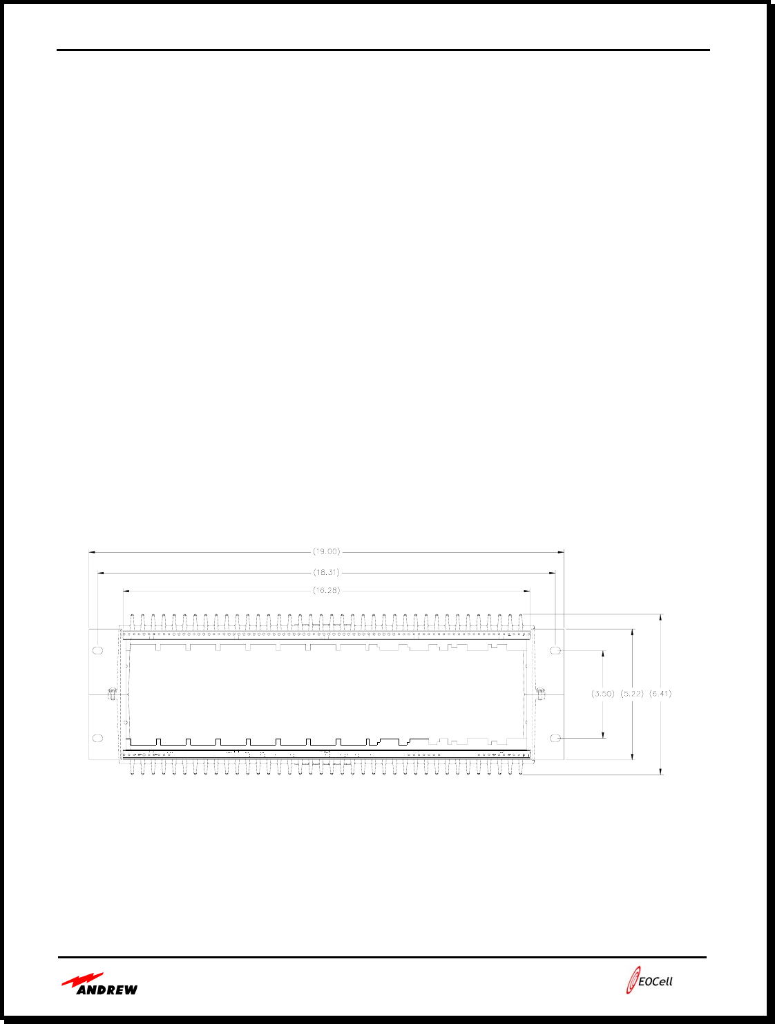
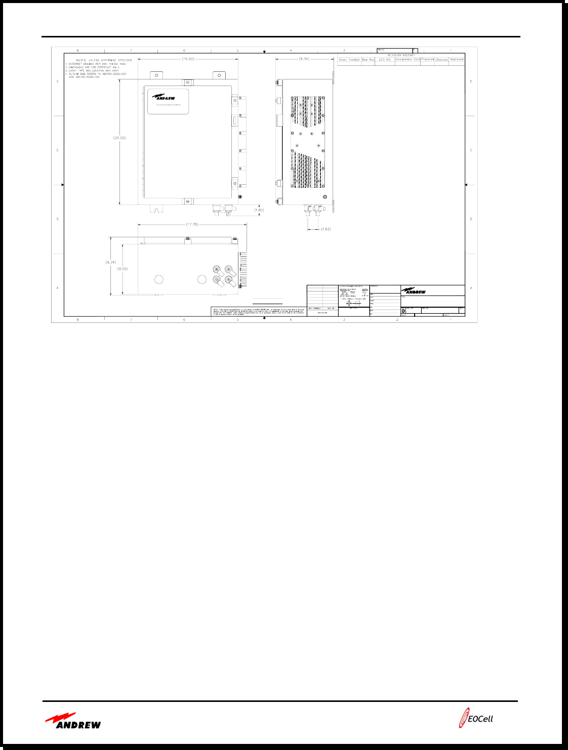
Master Rack Chassis Dim. 19 in. x 15.8 in. x 6.41 in.
Remote Amplifier Chassis Dim. 20 in. x 16 in. x 8 in.
Remote Amplifier Enclosure Type Wall Mount
Fiber Optic Connections FC/APC
Fiber Optic Cable Single Mode
Table 1-2. 2400 MHz EOCell™ Transceiver System Specification
1-6
• 2400 MHz EOCell™ Transceiver System Theory of Operation
Since no two in-building or tunnel coverage requirements are the same, in-building/tunnel RF
coverage solutions may involve one or a combination of RF coverage methods. Andrew can
provide several solutions to optimize the indoor RF coverage for a wide range of indoor
applications. The 2400 MHz EOCell™ Transceiver System complements other Andrew in-
building RF coverage methods such as passive and active leaky feeder RF distribution networks
using Radiax cable, passive distributed antenna systems and active distributed antenna systems.
In-building wireless systems are typically connected to a BTS / radio system located within the
building.
The 2400 MHz EOCell™ Transceiver System uses low loss single mode fiber optic cables to
distribute the uplink and downlink signals throughout buildings or tunnels.
The 2400 MHz EOCell Transceiver System uses direct analog modulation of the RF signal onto
the optical signal through a laser diode. The modulated optical signal from the laser travels over
the fiber optic cable to a photo diode, which converts the optical signal back to an electrical
signal. There is no frequency conversion (i.e. mixing the signal up and down to an IF
frequency). Because of the direct RF to optical conversion, the 2400 MHz EOCell system is
technology transparent, easily passing any type of modulation.
Master Fiber Optic
Transceiver Chassis
E
O
EO
DL
UL
Up to 8 RFFAUs Remote Fiber
Fed Amplifier Unit Radiax
Radiax
Duplexer
DL
UL
1:3
To/From BTS or
Radio
To/From
MFOTC
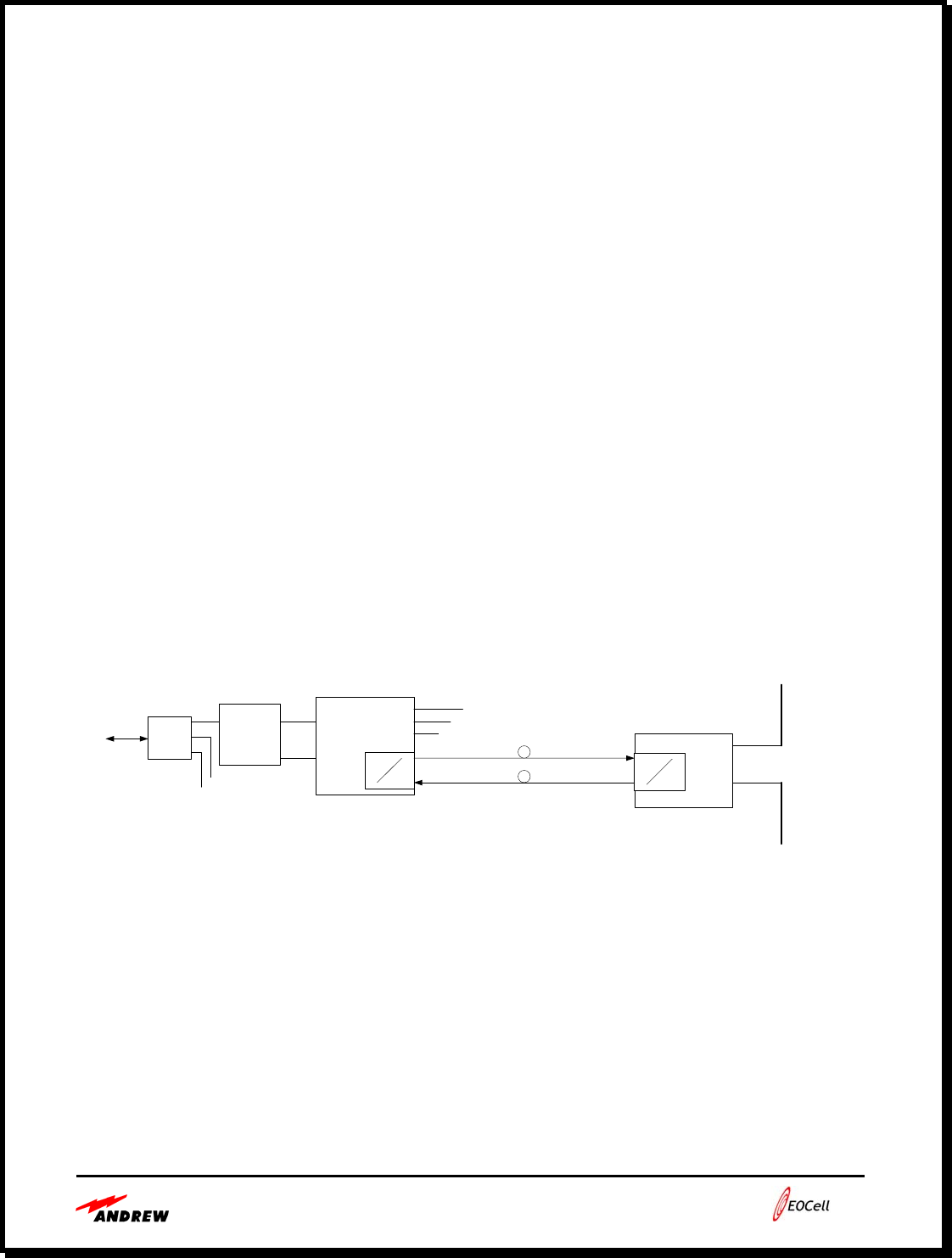
Figure 1-2. 2400 MHz EOCell™ Transceiver System Block Diagram

1-7
• Downlink Signal Flow
The downlink signal is the signal that is transmitted from the base station / base radio and
received by the portable or mobile radio. In the 2400 MHz EOCell™ Transceiver System the
MFOTC receives the downlink RF signal from a base station / base radio, converts the signal
into multiple identical optical signals and distributes the optical signals to RFFAUs that are
located throughout the coverage area. The RFFAU receives the optical downlink signal and
converts it back to an RF signal, which is then broadcast to portable and mobile radios located
within the coverage area.
If the 2400 MHz EOCell Transceiver System is connected directly to indoor base station / base
radio equipment, the downlink is supplied to the MFOTC via a coax cable from the base station /
base radio.
The wireless downlink signal is received through the Type N connector on the rear panel of the
MFOTC and is split into multiple identical RF signals, one for each fiber optic transceiver in the
MFOTC. A laser diode at each MFOTC transceiver converts the RF signal into an optical signal.
The optical signal for each MFOTC transceiver is transmitted through the Tx fiber optic
bulkhead connector, through a single mode fiber optic cable to the Rx fiber optic connector on
the RFFAU.
The RFFAU converts the optical downlink signal back to an RF signal using a photodiode. The
RF downlink signal is amplified, filtered and then passed through the RFFAU Type N connector
to an antenna or leaky feeder cable where it is transmitted to the portable or mobile radio.
• Uplink Signal Flow
The uplink signal is the signal that is transmitted from the portable or mobile radio and received
by the base station / base radio. In the 2400 MHz EOCell Transceiver System, an antenna or
leaky feeder cable receives the uplink RF signal from the portable or mobile radio and passes the
uplink signal to the RFFAU through the Type N connector located on the bottom panel of the
RFFAU. The RFFAU amplifies and filters the uplink RF signal and then converts the RF signal
into an optical signal using a laser diode. The optical signal passes through the Tx fiber optic
connector, through a single mode fiber optic cable to the Rx fiber optic bulkhead connector on
the MFOTC.
The MFOTC converts the received optical uplink signal back to an RF signal with a photodiode.
The uplink signals from each of the remote amplifier units are combined together to pass through
the Type N RF connector on the back of the MFOTC and then up to the base station / base radio.

Users Guide - Andrew 2400 EOCell™ Fiber Optic Distributed Antenna System
2-1
Section 2:
2400 MHz EOCell™ Transceiver System Equipment Description
MFOTC Description Page 2-2
MFOTC AC Power Interface Page 2-3
MFOTC RF Interface Page 2-3
MFOTC Optical Interface Page 2-3
MFOTC Front Panel Page 2-3
MFOTC Rear Panel Page 2-5
2400 MHz EOCell ™ Remote Fiber Fed Amplifier Unit (RFFAU) Page 2-5
RFFAU RF Interface Page 2-5
RFFAU Optical Interface Page 2-7
RFFAU Bottom Panel Page 2-8
Users Guide - Andrew 2400 EOCell™ Fiber Optic Distributed Antenna System
2-2
• MFOTC Description
The Master Fiber Optic Transceiver Chassis (MFOTC) is the central hub of the 2400 MHz
EOCell™ Transceiver System. The MFOTC is housed in a standard 4U tall, 19” rack mount
chassis for mounting in equipment racks or telecom racks. The MFOTC interfaces to the
external wireless infrastructure through an in-building base station / base radio that sends and
receives signals to an outdoor base station / base radio that is located nearby the building.
The MFOTC simultaneously passes the RF downlink signal from the base station / base radio to
the indoor portable and mobile radios while passing RF uplink signals from the indoor portable
and mobile radios to the base station / base radio. The MFOTC splits the downlink RF signals
for distribution to up to eight (8) Remote Fiber Fed Amplifier Units (RFFAUs) via fiber optic
interfaces. The MFOTC also receives and combines the uplink signals from up to eight (8)
RFFAUs for distribution to the base station / base radio.
For system fault detection, the MFOTC transceivers communicate alarms on an FSK sub-carrier
that is used to continuously monitor uplink and downlink signal paths. Faults with any of the
RFFAUs or any of the optical downlink or uplink cables cause software alarms available from
the alarm board in the MFOTC. The LEDs on the RRFAU and MFOTC transceivers will also
show errors as described in table 5-1.
The MFOTC chassis is equipped for rack mounting in standard equipment racks as mentioned
above.
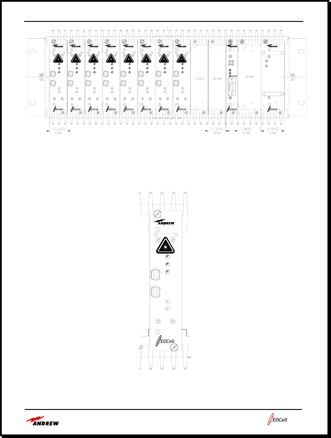
Figure 2-1. 2400 MHz EOCell™ Master Fiber Optic Transceiver Chassis (MFOTC)

Users Guide - Andrew 2400 EOCell™ Fiber Optic Distributed Antenna System
2-3
MFOTC features are listed below:
• MFOTC functions as the heart of the Distributed Antenna System (DAS).
• Multiple MFOTCs may be used together to create large DAS systems.
• MFOTC with an alarm board can provide continuous system fault detection via an RS-
232 connection.
• Easily installed in a standard 19” equipment rack or telecom rack.
• MFOTC AC Power Interface
To allow operation in a wide number of applications and locations, the MFOTC operates from
international AC power. The MFOTC uses 110 to 230 VAC, 50-60 Hz. The MFOTC uses
approximately 100 watts of power when a full system of eight (8) RFFAUs, one (1) Alarm
Module and one (2) AC/DC Power Supplies are mounted in the chassis.
• MFOTC RF Interface
The MFOTC RF interface is through the Type N connectors located on the rear panel. The
Type-N RF connectors are uni-directional. The downlink connector passes RF downlink signals
from the base station / base radio to portable and mobile radios and the uplink connector passes
RF uplink signals from portable and mobile radios to the base station / base radio.
• MFOTC Optical Interface
The MFOTC optical interface is through the fiber optic connectors located on the front of the
MFOTC. Each optical transceiver has a pair of fiber optic links. The downlink path carries the
optical signal from the base station / base radio to the RFFAU for transmission to portable and
mobile radios. The uplink path carries the optical signal from the RFFAU to the MFOTC to
transmit the signal from portable and mobile radios to the base station / base radio.
The MFOTC and RFFAU fiber optic connections are all type FC/APC. The system uses single
mode fiber optic cables to provide low loss, and wide bandwidth signal capabilities.
• MFOTC Front Panel
The figure below provides a detailed view of the MFOTC front panel, showing eight (8)
transceivers. Each of the eight (8) transceivers are identical and provide an optical downlink
interface and an optical uplink interface with an RFFAU.
Each RFFAU has Data, Tx and Rx LEDs. These indicators provide the status of the Remote
Fiber Fed Amplifier Unit and the fiber optic uplink and downlink signal paths. The status
indicators are described in table 5-1.
Users Guide - Andrew 2400 EOCell™ Fiber Optic Distributed Antenna System
2-4
ALM1
PSU2
Transceiver
Fiber
Rx
Tx
Rx
Rx
Tx
Data
Tx
Transceiver
Fiber
Rx
Tx
Rx
Rx
Tx
Data
Tx
RxD
Faults
TxD
2
1
pph6-.375
Transceiver
Fiber
Rx
Tx
Rx
Rx
Tx
Data
Tx
Transceiver
Fiber
Rx
Tx
Rx
Rx
Tx
Data
Tx
Transceiver
Fiber
Rx
Tx
Rx
Rx
Tx
Data
Tx
Power Supply
DC/DC
AC/DC
Alarm
CPU
Local
Transceiver
Fiber
Rx
Tx
Rx
Rx
Tx
Data
Tx
Transceiver
Fiber
Rx
Tx
Rx
Rx
Tx
Data
Tx
Transceiver
Fiber
Rx
Tx
Rx
Rx
Tx
Data
Tx
Figure 2-2. MFOTC Front Panel
Transceiver
Fiber
Rx
Tx
Rx
Rx
Tx
Data
Tx
Figure 2-3. Details of a MFOTC Fiber Optic Transceiver
Users Guide - Andrew 2400 EOCell™ Fiber Optic Distributed Antenna System
2-5
• MFOTC Rear Panel
The rear view of the MFOTC, figure 2-4 below, shows the Type N RF input & output connectors
as well as the AC power connection. The DB-9 connectors are for the optional remote
monitoring via a serial interface. The details of the remote alarms are discussed in section 5 of
this manual.
pph6-.375
TRANSMIT
3A 250V
FUSE
115/230 VAC
ALARM MODULE
PORT 1
RS-232
RECEIVE
PORT 2
RS-232
ALARM MODULE
115/230 VAC
Figure 2-4. MFOTC Rear Panel
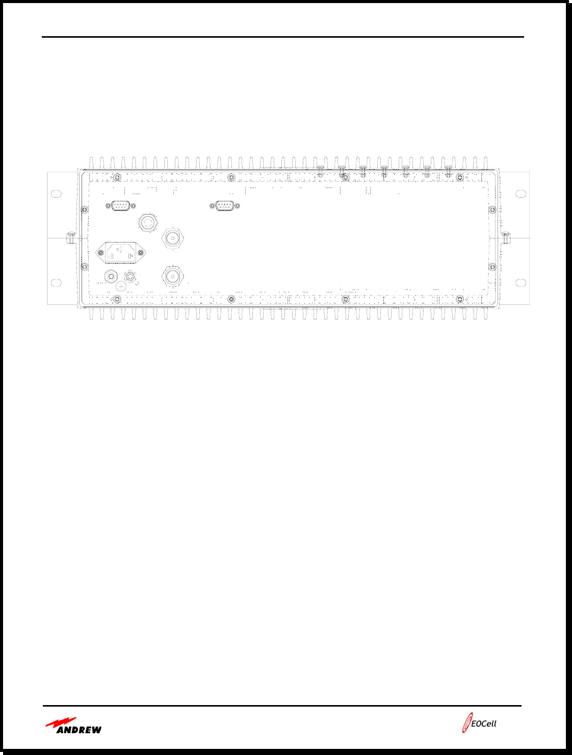
• 2400 MHz EOCell ™ Remote Fiber Fed Amplifier Unit
(RFFAU)
The RFFAU is the EOCell™ component that is distributed within a building or tunnel to provide
the RF signal interface to the portable and mobile radios. The RFFAU interfaces to antennas
and/or leaky cable to transmit the downlink signal to the portable and mobile radios and to
receive the uplink signal from the portable and mobile radios. Typical distributed antenna
systems consist of multiple RFFAUs connected to the MFOTC. The RFFAUs are a NEMA 4X
enclosure generally mounted on a wall. Reference figure 2-5 for the RFFAU diagram.
Users Guide - Andrew 2400 EOCell™ Fiber Optic Distributed Antenna System
2-6
Figure 2-5. RFFAU Enclosure Diagram
The RFFAU weighs ≤ 59 lbs and is 20 in. x 16 in. x 8 in. in size.
RFFAU features are listed below:
• The RFFAU provides high output power and sensitivity to cover large areas.
• The RFFAU is easy to install on a wall or a pole.
• Uses Type N female connectors for input/output interface to antennas or leaky cable.
• Uses Fiber Optic FC/APC Connectors for interfacing the fiber system
• RFFAU operates from a wide range of AC input: uses 110 to 230 VAC @ 50-60 Hz
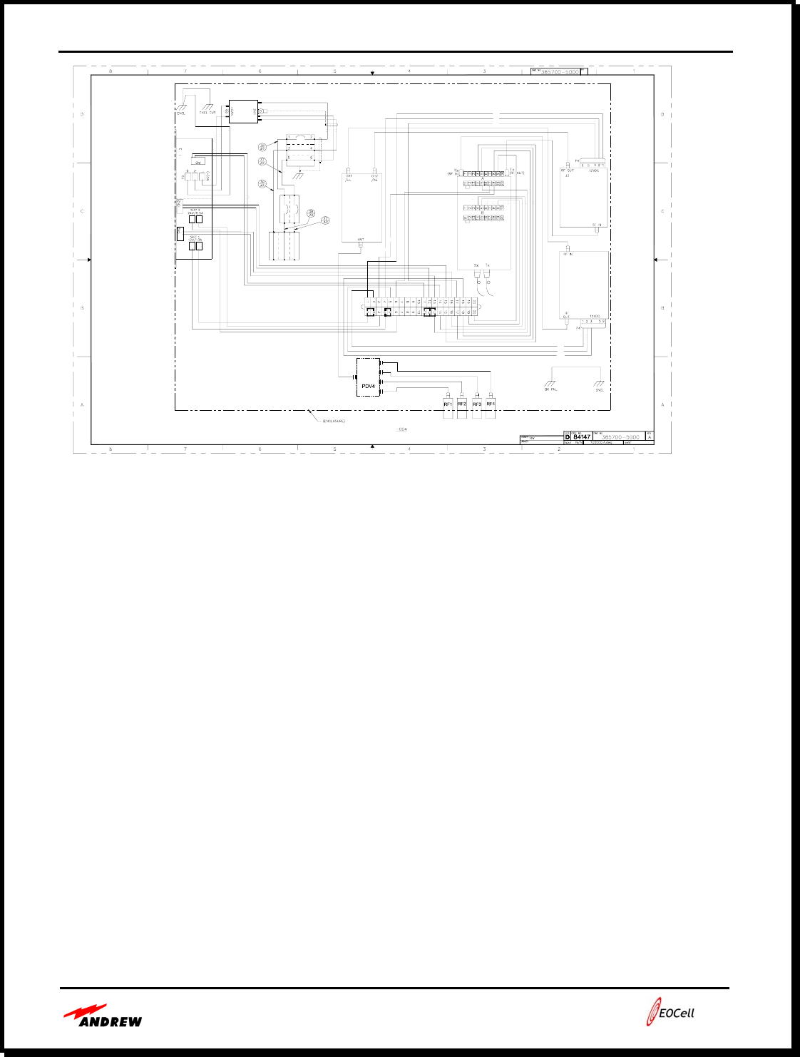
Reference the RFFAU schematic in Figure 2-6 below for component layout.
RF 4 RF 3
385700-5000-104
385700-5000-004
OUTLINE, REMOTE UNIT
84147
ART
2601 TELECOM PARKWAY
Richardson, Texas 75082-3521
COMPUTER GENERATED - DO NOT REVISE MANUALLY
110-230 VAC
RF 2
FO
RF 1RF 1
Users Guide - Andrew 2400 EOCell™ Fiber Optic Distributed Antenna System
2-7
Figure 2-6. RFFAU Schematic Diagram
• RFFAU RF Interface
The RFFAU RF interface is through the Type N Connectors located on the bottom of the unit.
All RF connectors pass RF downlink and uplink signals from the base station / base radio to the
portable and mobile radios. The RFFAU is typically connected to an antenna, directional
antenna or leaky cable. The RFFAU RF outputs may be configured for one (1), two (2), three (3)
or four (4) RF outputs. Reference Figure 2-5 above for the RF port locations.
• RFFAU Optical Interface
The RFFAU optical interface is through a set of fiber optic connectors located inside the unit.
These connectors are located on a fiber optic transceiver housed within the RFFAU’s chassis.
Fiber cable access into the RFFAU’s chassis is through a knockout located on the bottom panel.
The optical interface provides the uplink and downlink signal paths between the RFFAU and the
MFOTC. The downlink path carries the optical signal from the MFOTC to the RFFAU for
transmission to portable and mobile radios. The uplink path carries the optical signal from the
RFFAU to the MFOTC to transmit the signal from portable and mobile radios to the base station
/ base radio.
The RFFAU fiber optic transceivers use FC/APC type connectors. The EOCell System uses
single mode fiber optic cables to provide low loss and wide bandwidth signal capabilities.
W14
W4
W3W1
W2
PS1
W11
W4
W3
TB1
W2
W1
W10
B
A
W10
W9
W8
FTTB1
W6
W9
W8
W9
XVR1
LNA1
W8
DXR1
CB1
W12
W7 W10
W10
W10
W10
SVP1
FLT1
W9
PA1
-
WHT
BLK
BLU
BLU
BLK
WHT
W16 W15
W16
W19
W19
W17
W17
RED
W7
W5
W7
12
+
-+
5
6
5
6W5
W8
W10
BLK
W6
W15
W13
W19
W18
Users Guide - Andrew 2400 EOCell™ Fiber Optic Distributed Antenna System
2-8
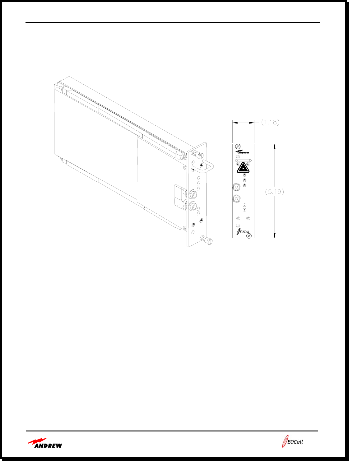
Reference Figure 2-7 below to view a transceiver module which is housed in the MFOTC. The
module in the RFFAU is very similar, but has a slightly different housing.
Figure 2-7. Fiber Optic Transceiver Module
• RFFAU Bottom Panel
Reference Figure 2-5 for a drawing of RFFAU bottom panel. Figure 2-5 shows the fiber optic
and AC input cable knockouts.
The bottom view of the RFFAU also shows the Type N RF connectors that are typically used to
connect to an antenna or leaky cable.
Although most antennas and leaky cables have a run of coax feeder cables and jumpers, an
adapter may be needed if the antenna jumper or feeder cable does not have a Type-N male
connector on the end.
The RFFAU bottom panel may be equipped with one, two, three or four bulkhead RF connectors
for multiple RF antenna ports. Reference Figure 2-5 above for the port locations.
Transceiver
Fiber
Rx
Tx
Rx
Rx
Tx
Data
Tx

Users Guide - Andrew 2400 EOCell™ Fiber Optic Distributed Antenna System
3-1
Section 3:
2400 MHz EOCell™ System Cabling
MFOTC – RFFAU Cabling Page 3-2
EOCell System Cabling Flexibility Page 3-2
Single Mode Fiber Optic Cable Page 3-3
Fiber Optic Connectors Page 3-3
Users Guide - Andrew 2400 EOCell™ Fiber Optic Distributed Antenna System
3-2
• MFOTC – RFFAU Cabling
To connect an RFFAU to any transceiver of the MFOTC, the downlink and the uplink signals
must be connected using single mode fiber optic cables with Type FC/APC connectors. Each
MFOTC can interface with up to eight (8) RFFAUs.
For each of the optical transceivers in the MFOTC, make the following connections:
• Connect the Tx connector on the MFOTC to the Rx connector on the RFFAU.
• Connect the Rx connector on the MFOTC to the Tx connector on the RFFAU.
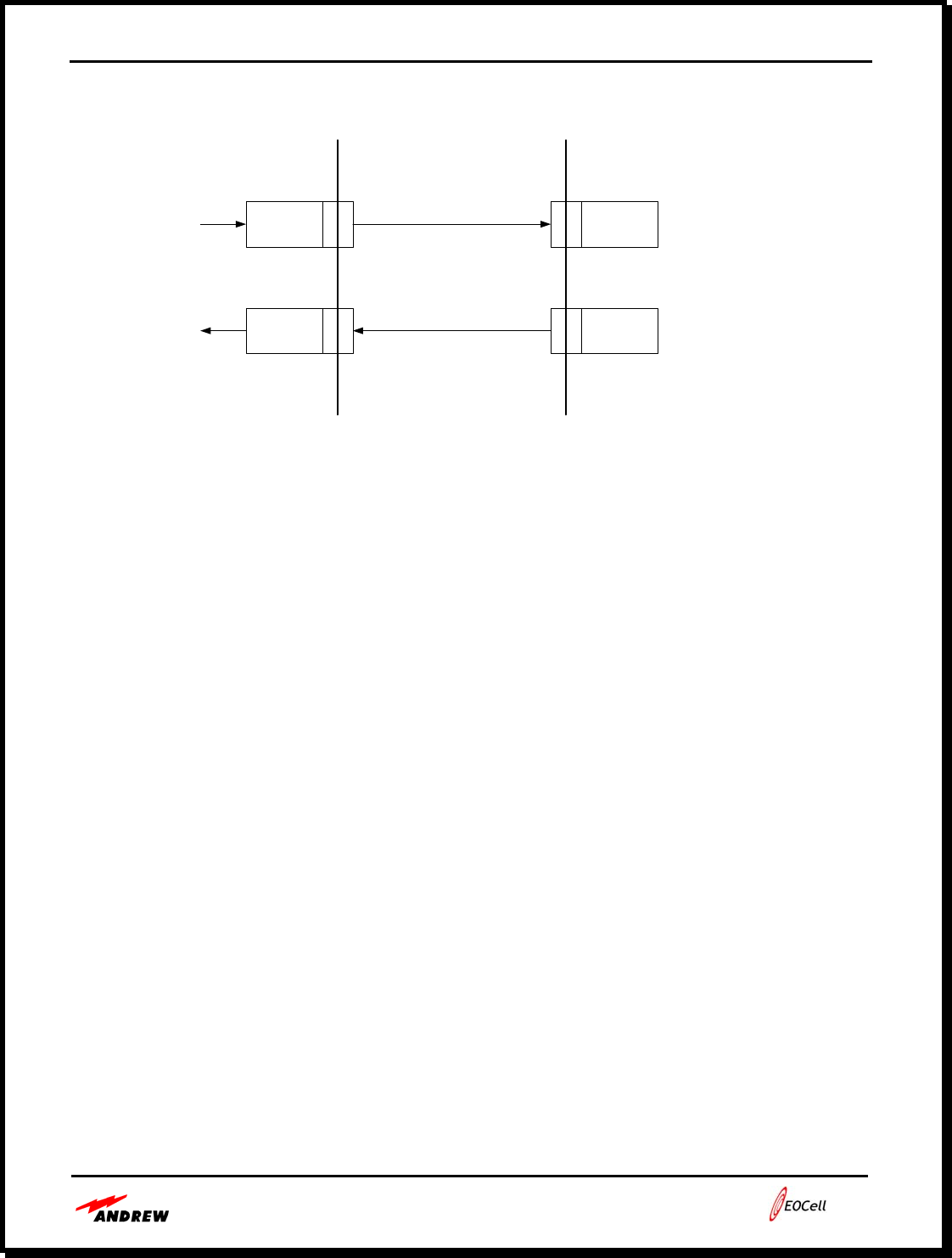
Figure 3-1 shows the basic uplink and downlink fiber connections between the MFOTC and the
RFFAU.
Cable Installation Aid
Andrew fiber optic cables have fiber cable markers or use different
color fiber jackets to aid in installation
Cable Route Mapping
It is good practice to have a system diagram or building map and label
the fiber optic cable ends at the MFOTC. This helps during
troubleshooting cabling and equipment problems.
• EOCell System Cabling Flexibility
It has been Andrew’s experience that system installation labor costs are typically higher than the
cost of the equipment being installed. For maximum flexibility, ease of installation and lowest
cost, EOCell™ Remote Fiber Fed Amplifier Units may be connected to the MFOTC hub in
several ways. Designers and installers may determine the lowest cost approach for each specific
application.
Users Guide - Andrew 2400 EOCell™ Fiber Optic Distributed Antenna System
3-3
Figure 3-1. EOCell Uplink and Downlink Flow Diagram
EOCell system cabling features:
• Flexible system design allows several cabling methods to be used
• Only one small diameter cable is needed between the MFOTC and each RFFAU
• Can use industry standard duplex single mode fiber optic cables
• Each RFFAU will need to be locally powered
• Andrew can provide duplex cable with plenum or riser rated jackets
• Single Mode Fiber Optic Cable
Single mode fiber optic cable is used in the EOCell™ products because of its wide bandwidth
and low attenuation characteristics. Single mode fiber optic cable has the lowest attenuation of
all fiber optic cable types and is typically lower in cost than multimode fiber cable. Single mode
fiber is used in communications systems where high data rates and wide bandwidths are
required. Wideband fiber optic cable provides for unlimited future growth. Typical single mode
cable loss is 0.4 dB per km. Each SC/APC connector has typically 0.5 dB loss.
• Fiber Optic Connectors
The FC/APC type connector is one of the most popular connector types for analog use fiber-
optic cables. It provides a very reliable, low loss connection at a reasonable cost. The FC/APC
type connector is easy to install and provides positive feedback when correctly seated. FC/APC
connectors are keyed with good pull and wiggle characteristics, ensuring that they will stay in
place when installed and that they are immune to tension or lateral pressure on the fiber cable.
Photo
Diode Laser
Photo
Diode
RF Downlink
RF Uplink
Tx Rx
MFOTC RFFAU
Laser
Rx Tx

Users Guide - Andrew 2400 EOCell™ Fiber Optic Distributed Antenna System
3-4
As with any fiber optic connector, the optical end should be kept clean and be dusted with air-
spray prior to insertion into a MFOTC or RFFAU. If good optical contact is not maintained,
there can be link failure or high noise figure, as considerable back reflections could result in a
higher-than-normal noise floor in the antenna link. To keep the cables clean during shipping and
installation, a protective dust cap is used on each fiber connector provided by Andrew. The
RFFAU and MFOTC optical bulkhead connectors are also provided with dust caps to ensure
optimal connections.
Fiber Optic Installation Note
For installation in plenum areas, plenum-rated cable jackets are required to meet
local and US safety codes. Fiber optic cables are available for many uses and
with many types of outer coatings. Take care to ensure that only plenum rated
cables are used where required

Users Guide - Andrew 2400 EOCell™ Fiber Optic Distributed Antenna System
4-1
Section 4:
Implementations Using the Andrew EOCell™ System
EOCell™ Installation Parameters Page 4-2
EOCell MFOTC Installation Page 4-2
Scalable System Architecture Page 4-4
EOCell RFFAU Installation Page 4-4
Field Installation of Point-to-Point Antennas Page 4-5
Typical MFOTC to RFFAU Interface Implementation Page 4-10
Operation Page 4-11
Preventative Maintenance Page 4-11
Fault Repair Page 4-11
Technical Support Page 4-11

Users Guide - Andrew 2400 EOCell™ Fiber Optic Distributed Antenna System
4-2
• EOCell™ Installation Parameters
Installation times will depend on the size of each installation; however, Andrew can provide
rough guidelines for installing the MFOTC and RFFAU that may be used to determine the total
system installation time once the number of equipment parts are determined.
Disruption to business is minimal as the MFOTC is typically installed in an electronic equipment
room and the remote units, wiring, antennas and leaky cable is installed after work hours.
Site survey testing before and after installation may be done during business hours using small,
portable RF measurement tools.
• EOCell MFOTC Installation
The MFOTC may be mounted in indoor areas in a standard 19” equipment rack, a 19” telecom
rack or on a wall.
Mount the MFOTC in the rack so that there is open air or moving air around the MFOTC. Take
care to ensure that the ventilation fins of the MFOTC are not blocked. The MFOTC uses
universal AC power for maximum flexibility and has a standard IEC connector for the AC cable
connection. If possible, use of an uninterruptible power supply (UPS) to supply power the
MFOTC is suggested. A ground lug is provided for connecting the MFOTC chassis to the
ground circuits of other equipment.
Allow 30 minutes for unpacking the MFOTC, installing the unit into the rack or wall and
connecting the RF, fiber and power cables. Upon application of system power, front panel
indicators will give the installer a visual indication of power and link status.
To ensure trouble free connections, all fiber optic connectors on the MFOTC and their mating
cable connectors should be thoroughly cleaned using high purity (95%) alcohol and dry
compressed air.
Care should also be taken to ensure that the fiber optic cables are routed cleanly to the MFOTC
and that they are not kinked or bent with less than a 2” bend radius. Also, cables should be
routed away from sharp edges that could cause abrasion or cause dents in the cable over a period
of time.
Users Guide - Andrew 2400 EOCell™ Fiber Optic Distributed Antenna System
4-3
Unused MFOTC Transceivers
Any transceivers in the MFOTC that are not connected to an RFFAU will cause
the built-in-test system to indicate a link error condition. This error condition
will be seen on the MFOTC front panel LED indicators and will also appear as a
link error in the alarm board software connection.
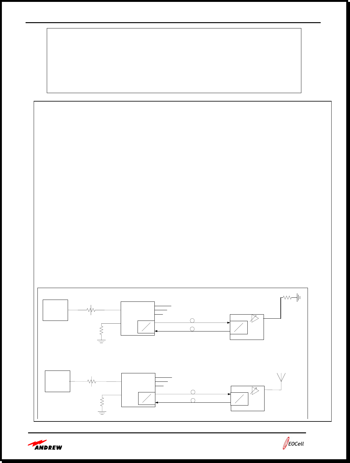
Mandatory Installation Notes
1. Do not operate unit above 60 degrees Celsius.
2. Installation of the equipment in a rack should be such that the amount of
airflow required for safe operation of the equipment is not compromised.
3. Mounting of the equipment in the rack should be such that a hazardous
condition is not achieved due to uneven mechanical load.
4. The system is designed to comply with FCC, DGT and EN 300 328-2 as long
as the following setup parameters are followed (see diagrams below):
a. Fiber loss must be < 9dBo to ensure link noise is not exceeded
b. The maximum output channel power must be < 23dBm
c. Horn antennas are NOT to be used in countries where EN 300 328-2
compliance is needed.
d. Horn antennas in countries complying with FCC and DGT must be ≤
12dBi.
e. Horn Antenna must be for fixed, outdoor use only.
Master Fiber Optic
Transceiver Chassis
E
O
EO
DL (9dBo Atten)
UL
Remote Fiber
Fed Amplifier Unit
DL
UL
Set Radio
Power
Set Attenuator
50 Ohm
HORN 12dBi
DL
Set
Pout
= 23 dBm
Max
(Ch. Pwr)
FCC & DGT ONLY
Wireless Test Setup
12dBi H
Master Fiber Optic
Transceiver Chassis
E
O
EO
DL (9dBo Atten)
UL
Remote Fiber
Fed Amplifier Unit
Radiax
DL
UL
Set Radio
Power
Set Attenuator
50 Ohm
50 Ohm
DL
Set
Pout
= 23 dBm
Max
(Ch. Pwr)
FCC, DGT &
EN 300 328-2
Wireless Test Setup
Radiax
Configuration
Users Guide - Andrew 2400 EOCell™ Fiber Optic Distributed Antenna System
4-4
• Scalable System Architecture
The EOCell™ distributed antenna system is a scalable system that can be configured to support
small or large numbers of remote fiber fed amplifier units, depending on the building or tunnel
size. Very large systems may be configured by using standard power divider/combiners to
combine multiple MFOTCs together.
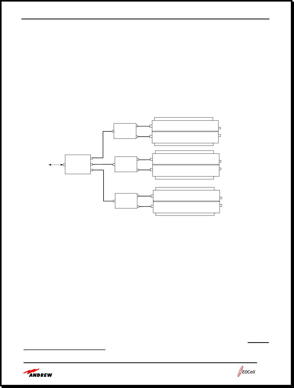
A 3-way power divider can combine signals to/from 3 MFOTCs to support up to twenty-four
(24) RFFAUs. Care should be taken to consider the RF loss through the power dividers to
ensure that sufficient signals levels are present for uplink and downlink operation.
Figure 4-1. System expandability to 24 RFFAUs
• EOCell RFFAU Installation
RFFAUs are typically mounted on the wall throughout the building or tunnel according to a
design drawing. Upon application of system power, indicators on the RFFAU give the installer a
visual indication of RFFAU power and link status.
Allow 45 minutes for installing the RFFAU and connecting the antenna/leaky cable, fiber and
power cables. Upon application of system power, indicators inside the RFFAU will give the
installer a visual indication of power and the downlink link status.
Connect the system feeder cable to the RFFAU Type N connector and ensure that the connector
is tight, but do not over-tighten and damage the RFFAU connector.
If necessary, power output adjustment of the RFFAU may be accomplished by a trained,
professional service technician by adjusting the PA potentiometer in the RFFAU.
Duplexer
Duplexer
Duplexer
RF Power
Divider/
Combiner
To/From
BTS /
Radio
To/From
8 RFFAUs
To/From
8 RFFAUs
To/From
8 RFFAUs
MFOTC
MFOTC
MFOTC

Users Guide - Andrew 2400 EOCell™ Fiber Optic Distributed Antenna System
4-5
• Field Installation of Point-to-Point Antennas
NOTICE
The point-to-point antennas for the system must be professionally installed on permanent
structures for outdoor operations. The installer is responsible for ensuring that the limits
imposed by the FCC with regard to maximum Effective Isotropic Radiated Power (EIRP)
are not violated. These limits are described in the following sections.
• Antenna Installation
The Antenna Products Model ISM40-2400-12-T0 horn antenna is used for point-point operation.
It is a directional horn antenna with a 12 dBi gain, a 40-degree horizontal beamwidth (3dB) and a
40-degree vertical beamwidth (3dB). For optimum performance, the EOCell remote unit must
be mounted in close proximity to the horn antenna.
It is recommended to use low loss coaxial cable, such as Andrew Corporation FSJ4-50B Heliax,
with a maximum length of 6 meters (20 feet) between the EOCell remote ports and the horn
antenna.
Antennas at each link must have the same polarization, and it is recommended to have the horn
antennas both in the vertical polarization orientation.
Proper grounding of the antenna is important for lightning protection as well as to prevent
electrical noise from interference from other sources. The antenna should be mounted to a mast
or tower that is well grounded to Earth. Earth ground must be connected to the ground lug of the
case of the remote EOCell for proper operation of the lightning arrestors on the remote EOCell
unit.
• Antenna Alignment
When mounting a directional antenna, the proper alignment is extremely important since the
beamwidth of the antennas are 40-degrees. To ensure the proper alignment of the antennas, each
end of the link uses a Safetran model A55325 radio’s “poll-loop” utility.
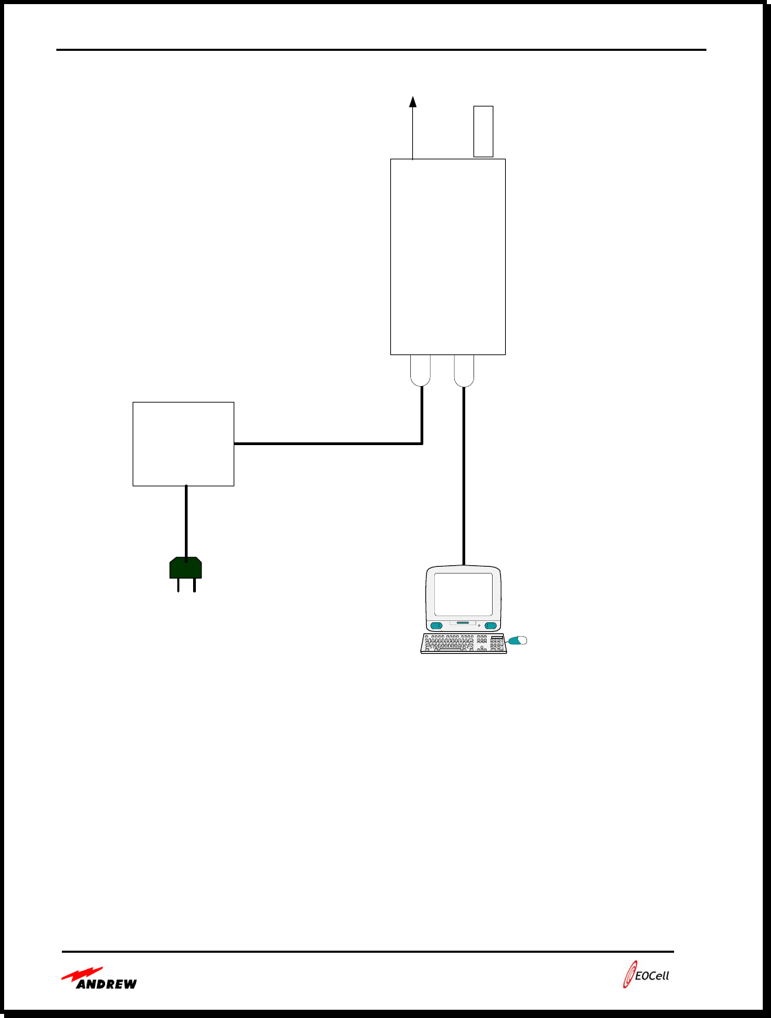
Connect a Safetran radio to the EOCell end of the coaxial cable for each end of the link.
Each radio comes with a power-inserter module, AC power cord, power cable (black), and
diagnostic cable (beige).
Users Guide - Andrew 2400 EOCell™ Fiber Optic Distributed Antenna System
4-6
Radio
AB
J1 J2
To
LAN
To
Radio
Power Inserter
Unit
Dummy
Load
To antenna
system
iMac
PC running
terminal program
J1 - 8-pin
J2 - 3-pin
Black cable
Beige cable
Figure 4-2. Radio Setup
• Run “Hyperterm” or other terminal emulation program for a standard RS-232
communications port: 9600 Baud, 8-bits, No parity, 1-stop bit.
• Connect the beige diagnostic cable between the PC and J2 of the radio.
• Connect the black power/data cable between “To radio” on the power inserter and J1 on
the radio.
• No cable is needed for the “to LAN” port on the power inserter.
• Plug in the power inserter to the AC power.
• Connect the antenna coaxial cable to the radio’s “A” antenna port. Connect a 50-Ohm
dummy load to the radio’s “B” antenna port.
Users Guide - Andrew 2400 EOCell™ Fiber Optic Distributed Antenna System
4-7
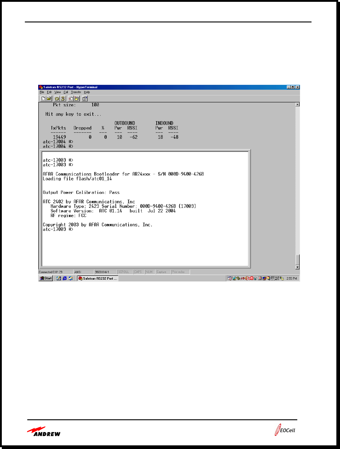
• Radio Configuration
• When radios are powered up, the “AFAR Communications Bootloader....” screen
appears on the Hyperterm window.
Figure 4-3. Boot up screen
Users Guide - Andrew 2400 EOCell™ Fiber Optic Distributed Antenna System
4-8
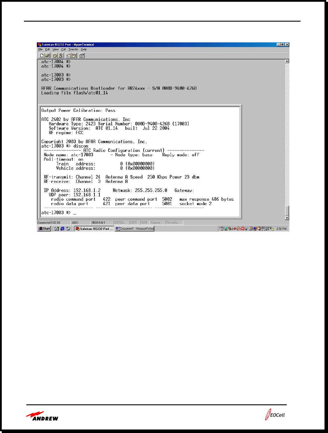
Figure 4-4. Displaying Configuration (discon) on the base
• To display how the radios are configured, type “discon” at the prompt.
• For one radio (referred to as end “A” of the link) configure the radio as a mobile radio,
setting the RF parameters per the following commands.
o node type=mobile va=1 ta=1
o rp tc=3 rc =24
o rp tp=20
o rp ra=a ta=a
• Return to the other end of the radio link (end “B”) and configure the radio as follows:
o node type=base
o rp tc=24 rc =3
o rp tp=20
o rp ra=a ta=a
Users Guide - Andrew 2400 EOCell™ Fiber Optic Distributed Antenna System
4-9
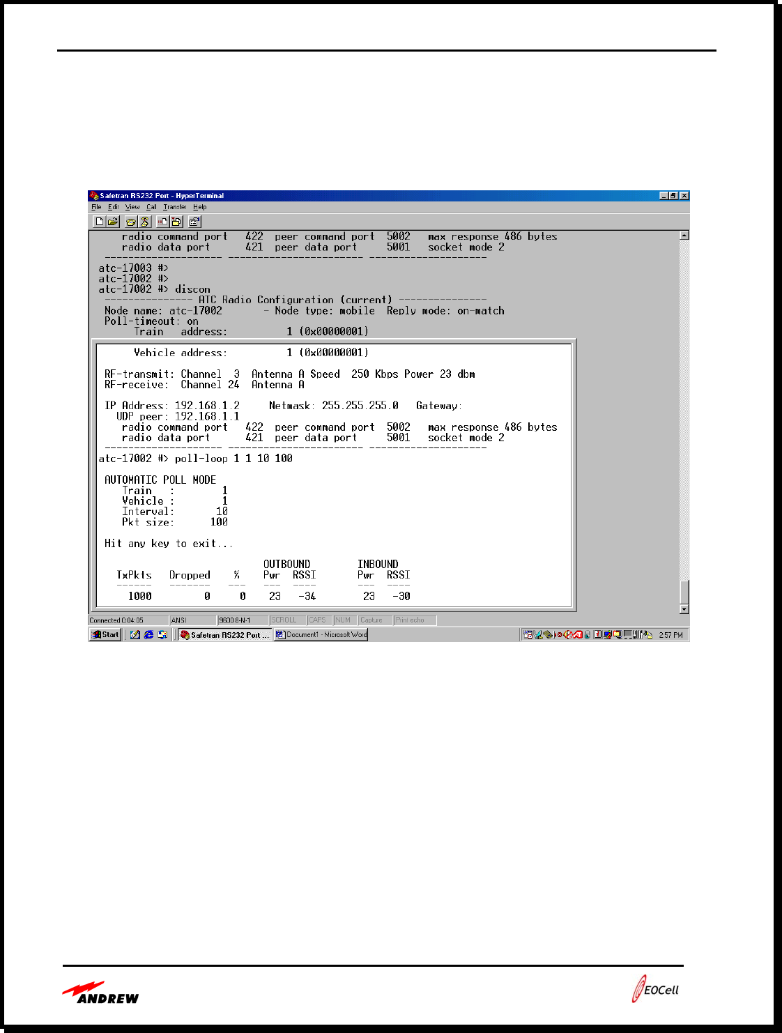
• Alignment using the Polling Test
At the base radio, start the poll-loop test....
Figure 4-5. Poll-Loop Test
• At the prompt, type:
o Poll-loop 1 1 10 100
• Use the poll-loop command is shown in Figure 4
o “poll-loop 1 1 10 100” will poll train address=1, vehicle address = 1, every 10
mS with a 100-Byte test packet. The mobile will loop the message back to the
base. The results are displayed at the bottom of Figure 5.
• Transmission from both the base and mobile are cyclic (<100 % duty cycle).
Adjust the direction of the antenna on each end to achieve the maximum RSSI
reading for both inbound and outbound directions.
Users Guide - Andrew 2400 EOCell™ Fiber Optic Distributed Antenna System
4-10
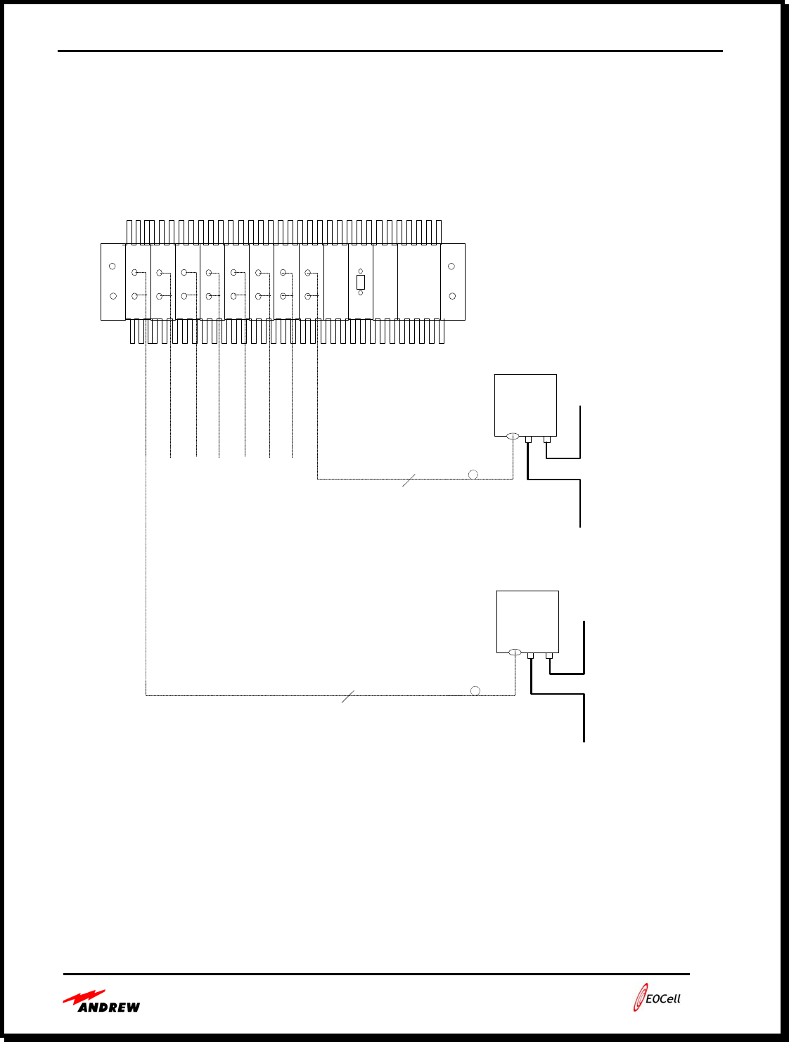
• Typical MFOTC to RFFAU Interface Implementation
Figure 4-6 shows an EOCell™ DAS connected to the RFFAU. The EOCell™ MFOTC
interfaces directly to the RFFAU via fiber optic cable. Typically, the MFOTC is located near the
BTS / radio in the same equipment closet with the base station / base radio. If signals from more
than 1 base station / base radio are to be distributed by the EOCell™ DAS, the base stations /
base radios will need to be combined using external power divider/combiners.
Figure 4-6. Typical MFOTC to RFFAU System Interface
Tx
Rx
Tx
Rx
Tx
Rx
Tx
Rx
Tx
Rx
Tx
Rx
Tx
Rx
Tx
Rx
AC/DC
ALR
RFFAU
RFFAU
# 1
# 8
.
.
.
.
.
2
2
RADIAX
RADIAX

Users Guide - Andrew 2400 EOCell™ Fiber Optic Distributed Antenna System
4-11
• Operation
EOCell™ system operation is continuous. Andrew recommends using an uninterruptible power
supply (UPS) to provide power to the MFOTC. This is especially useful for essential
communications links for security, facilities personnel, fire and police.
• Preventative Maintenance
Minimal maintenance is required to support installed EOCell™ systems. System maintainers
should ensure that all RF, power and fiber connectors are tight and that the MFOTC is mounted
with adequate room to allow air to flow around the chassis. Indicator LEDs show system status
while relay and optional remote alarm interfaces allow small or large system status to be
monitored.
Typically, after system installation, no removal or cleaning of the fiber connectors will be
required. Andrew does recommend using a commercially available fiber optic cleaning kit to
maintain clean fiber optic connectors that are removed.
• Fault Repair
If a fault is detected in the system, maintainers can determine the problem cause by reviewing
reports from the remote monitoring system or by observing the front panel LED indicators on the
MFOTC transceivers. Because the different MFOTC transceivers correspond to different
RFFAU locations, maintainers can determine where the problem exists in the building or tunnel.
Maintainers can replace RFFAUs in the building or tunnel without having to power down the
system. If a MFOTC fails, spare MFOTC modules can be installed.
• Technical Support
Andrew engineers and technicians familiar with the operation of the EOCell™ system are
available Monday through Friday, 8am to 5pm CST. These personnel are familiar with
distributed in-building antenna systems, with fiber optic cable installation and with
troubleshooting and in-building coverage solutions. They may be reached at (972) 952-9700.

Users Guide - Andrew 2400 EOCell™ Fiber Optic Distributed Antenna System
5-1
Section 5:
EOCell™ Network Monitoring Capabilities
FSK Generation Page 5-2
RFFAU Transceiver LED Indicators Page 5-3
MFOTC Transceiver LED Indicators Page 5-4
MFOTC Alarm Functions Page 5-4
Remote Monitoring Functions Page 5-5
SCADA Page 5-5
SCADA Protocol Page 5-6
Alarm Board Message Flow Page 5-7
Transceiver Message Flow Page 5-8
System Level Message Flow Page 5-9
16-Bit Check Sum algorithm Page 5-10
List of Messages Page 5-12

Users Guide - Andrew 2400 EOCell™ Fiber Optic Distributed Antenna System
5-2
The EOCell™ family is designed to minimize maintenance and monitoring costs. Provisions are
made for both local and remote monitoring of small and large systems. The EOCell™ system
continuously monitors and reports status of the system hardware, by a combination of indicators
available at the central hub (MFOTC) and at each remote amplifier unit.
The wideband, single mode fiber cable allows a low frequency RF test signal to be continuously
passed over the downlink and uplink signal paths with the RF wireless signals.
• FSK Generation
Each MFOTC transceiver generates a FSK communication link with its RFFAU for fault
detection and isolation. This low frequency FSK signal is combined with the downlink RF signal
and transmitted over the fiber optic cable to the RFFAU where it is received and filtered from the
downlink RF signal. In the RFFAU, the FSK is also generated, amplified and combined with the
RF uplink signal to be sent over the optical uplink path back to the MFOTC. Within the RFFAU
transceiver, the FSK is detected by a threshold detector to indicate the presence of the FSK at a
minimum signal level. The FSK threshold detector drives the “DATA” LED in the RFFAU (see
Table 1-5 below). This is an indication that the downlink optical signal path to the RFFAU is
connected. An identical process is repeated for FSK communication from the RFFAU to the
MFOTC.

Users Guide - Andrew 2400 EOCell™ Fiber Optic Distributed Antenna System
5-3
Table 5-1. MFOTC and RFFAU Transceiver LED Status
Xmt Amp LD
Current Receiver
Amp 1 Receiver
Amp 2 PD
Current FSK Amp Rx RSSI Tx FSK
Level Over/UnderTempLED LED
States
Green Good Good Good Good
Data Link Red Alarm Alarm Alarm Good or Alarm
"Data" Red
(Slow
Blink)
Good Good Alarm Good or Alarm
Red (Fast
Blink) Alarm Alarm Good Good or Alarm
Green
(Slow
Blink)
Alarm
Green Good Good Good
Transmit
RF Red Alarm Alarm Good or Alarm
"TX" Red
(Slow
Blink)
Good Alarm Good or Alarm
Red (Fast
Blink) Alarm Good Good or Alarm
Green
(Slow
Blink)
Alarm
Green Good Good Good Good
Receive
RF Red Alarm Alarm Alarm Good or Alarm
"RX" Red
(Slow
Blink)
Good Good Alarm Good or Alarm
Red (Fast
Blink) Alarm Alarm Good Good or Alarm
Green
(Slow
Blink)
Alarm
• RFFAU Transceiver LED Indicators
With the LED indicators illuminated, the RFFAU AC power is present at the RFFAU. If the
LED indicators are OFF power is required. Refer to table 5-1 above.
The receive LED on the RFFAU shows that light from the MFOTC laser is present over the
downlink. When the receive link indicator is GREEN on the RFFAU, the downlink optical path
between the MFOTC and the RFFAU is installed correctly and AC power is present in the
RFFAU. If the receive link indicator is RED or blinking, there may be a problem with the
internal RX amplifiers or the downlink optical path between the MFOTC and RFFAU. The
RFFAU indicators allow system installers and maintainers to easily determine the RFFAU
functional status, power status and the downlink optical path status.
Users Guide - Andrew 2400 EOCell™ Fiber Optic Distributed Antenna System
5-4
• MFOTC Transceiver LED Indicators
With the LED indicators illuminated, the MFOTC AC power is present. If all MFOTC LED
indicators are GREEN, AC power and optical power is good. Refer to table 5-1 above. If an LED
indicator is RED or blinking, there is problem with that corresponding MFOTC transceiver
interface. If the LED indicators for all MFOTC transceivers are OFF, the AC power supply may
be bad, AC power may be switched off or there may be another problem with the AC power.
The receive link indicator at each MFOTC transceiver shows that the laser light from each
RFFAU was sent over the uplink fiber from the RFFAU to the MFOTC. When the receive link
indicators are GREEN on the RFFAU, the uplink optical paths are installed correctly and AC
power is present in the RFFAU. If the receive link indicators are RED, there may be a problem
with the internal RX amplifiers or the fiber optic signal between the MFOTC and RFFAU; a
problem with the RFFAU power; or a problem with the RFFAU itself. The MFOTC indicators
allow system installers and maintainers to easily determine each RFFAU functional status, power
distribution to each RFFAU, and the correct connection of the fiber optic cables.
• MFOTC Alarm Functions
The MFOTC alarms may be accessed from an RS232 DB-9 Sub connector on the front panel of
the MFOTC alarm module or either of the back panel DB-9 connectors. This interface provides
the capability to monitor the RFFAUs from the MFOTC. The alarms are retrieved via software
(optional) available for the MFOTC systems. The following alarms are monitored by the
MFOTC: the RFFAU Rx and Tx amplifiers, the fiber optic transceiver Rx photo and Tx laser
diodes, the data RSSI, FSK amplifier, and over temperature alarm. The DB-9 RS-232 pin
outputs are referenced in the table below.
Table 5-2. Alarm Connector Pin Out
Alarm Connector Pin Alarm Pin Description
1, 4, 6-9 Not Used
2 Transmit Commands
3 Receive Commands
5 Ground

Users Guide - Andrew 2400 EOCell™ Fiber Optic Distributed Antenna System
5-5
Unused MFOTC Transceivers
Any transceivers in the MFOTC that are not connected to an RFFAU will cause
the built-in-test system to indicate a link error condition. This error condition
will be seen on the MFOTC front panel LED indicators and will also appear as a
link error in the alarm board software connection.
• Remote Monitoring Functions
NOTE: REMOTE MONITORING MAY BE PERFORMEND USING ANDREW
SOFTWARE OR SOFTWARE PROVIDED BY THE CUSTOMER.
EOCell™ Systems support optional remote system health monitoring using standard protocols
that allow customers to monitor full system status. This feature uses an embedded processor to
monitor and report system health for the MFOTC and all RFFAUs, including uplink and
downlink fiber paths and cables.
With this option, the EOCell™ System hardware can be monitored in a few ways:
• Locally at the MFOTC using an RS-232 connection to a terminal or PC.
• Remotely using an SNMP Agent chassis connected to a telephone, LAN/WAN or other
communications medium
• Remotely using an RS-232 to LAN converter
• SCADA (Supervisory Control and Data Acquisition)
SCADA (Supervisory Control and Data Acquisition) system is used in industrial and
comminication applications to control distributed systems from a master location. The EOCell
architecture of a SCADA solution involves physical equipment such as Transceivers, power
supply, amplifiers and other devices able to be controlled and monitored by an Alarm Board. The
dual role of the master computer or network management system (NMS) is to provide
information such as operational readings and equipment status to the human operator in a
digestible form and to allow the operator to control the EOCell equipment in predefined ways.
The EOCell SCADA deployment choose to restrict access to the master computer, and interface
with the system using operator consoles which communicate with the EOCell equipment over a
network using RS-232.
While the SCADA human-machine interface usually allows operators to view the state of any
part of the EOCell network, most operators interaction with the system is driven by alarms.
Users Guide - Andrew 2400 EOCell™ Fiber Optic Distributed Antenna System
5-6
Alarms are automatically detected by abnormal conditions in the EOCell network that require
operator attention, and may require operator intervention to keep things running smoothly.
SCADA protocol is designed to be very compact and is designed to send information to the
master station only when the master station polls the EOCell alarm board.
• SCADA Protocol
The SCADA Protocol uses two tries of messages: commands and responses. Each command or
request will cause the EOCell equipment to generate a response. All messages will conform to the
following format.
Destination
Address Originating
Address
SYNC1
Hex (C4) SYNC2
Hex (D7) Rack Tran
s Rack Tran
s
Command/
Response Data
Count Data
1..N Bytes Check
Sum
1 Byte 1Byte 1 Byte 1 Byte 1 Byte 1Byte 1 Bytes 1 Byte Data Bytes 2 Bytes
SYNC1 xC4
SYNC2 xD7
Destination Address: Rack 1 to 255
Destination Address: Transceiver 1 to 255
Originating Address: Rack 1 to 255
Originating Address: Transceiver 1 to 255
Commands CMD/RESP
Data Count Number of data bytes
Data Bytes Data
Check Sum 16 bit CRC
The command/response byte (CMD/RESP) is identical for a particular type of transaction, with the
exception that the high-order bit is set for the command and cleared for the response.
A response message will have the Destination Address and the Originating Address switched, so, the
routing of the response back to the originator can be accomplished.
An Alarm Board will always respond to commands with the default destination address of (0,0) and a
transceiver will respond to a default destination address of (255,255).
The Addressing scheme used for Local Transceiver is the slot number, Remote Transceiver is the Local
Transceiver plus a zero (i.e. Local Transceiver in slot 2 of Rack 1 would have a Transceiver Address of 2,
and the Remote Transceiver would be 20, all will have a rack address of 1).
Note: A Message with a bad CRC will be ignored and removed from the processing and not forwarded.
Users Guide - Andrew 2400 EOCell™ Fiber Optic Distributed Antenna System
5-7
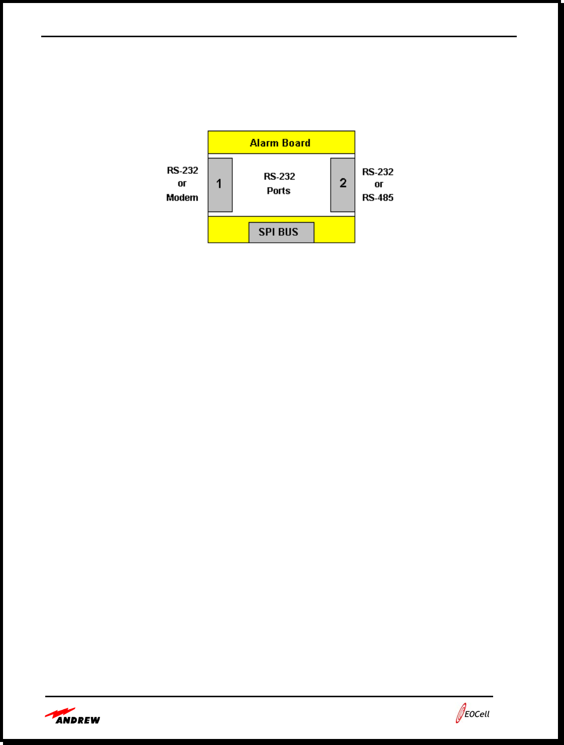
• Alarm Board Message Flow
The following rules are for routing messages between the ports on an Alarm Board:
o Commands arrived by Serial 1
o If requested Address matches then generate a response and swap both originating and
requested address then send the response back to Serial 1, else
o If Serial 2 = Active or Serial 2 = RS-485 Master then route command out Serial 2.
o If Alarm Controller = true then route command out SPI Bus.
o Response arrived by Serial 1
o If Serial 2 = Active or Serial 2 = RS-485 Master then route response out Serial 2.
o If Alarm Controller = true then route response out SPI Bus.
o Commands arrived by Serial 2
o If Address matches then generate a response and send to Serial 2, else
o If Alarm Controller = true then route command out SPI Bus.
o Route command out serial 1
Users Guide - Andrew 2400 EOCell™ Fiber Optic Distributed Antenna System
5-8
o Response arrived by Serial 2
o If Alarm Controller = true then route command out SPI Bus.
o Route response out serial 1
o Command arrived by the SPI Bus
o If Address matches then generate a response and send to SPI Bus, else
o If Serial 2 = Active or Serial 2 = RS-485 Master then route command out Serial 2.
o Route command out serial 1
o Response arrived by the SPI Bus.
o If Serial 2 = Active or Serial 2 = RS-485 Master then route response out Serial 2.
o Route response out serial 1
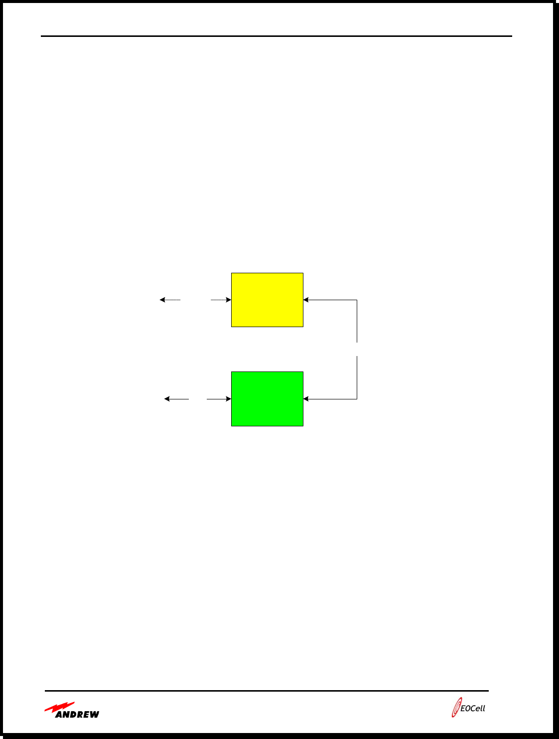
• Transceiver Message Flow
Processor
FSK
Modulator/
Demodulator
RS-232
SPI
Fiber
Optics
The following rules are for routing messages between the ports on a Transceiver:
o Commands arrived by the RS-232 (fiber optics)
o If Address matches then generate a response and send to RS-232, else
o Buffer the command data for the Alarm Control Board to receive over the SPI Bus
o Response arrived by the RS-232 (fiber optics)
o Buffer the response data for the Alarm Control Board to receive over the SPI Bus
o Commands arrived by the SPI Bus
o If Address matches then generate a response and buffer response data, else
o Route command out the RS-232
o Response arrived by the SPI Bus
o Route response out the RS-232
Users Guide - Andrew 2400 EOCell™ Fiber Optic Distributed Antenna System
5-9
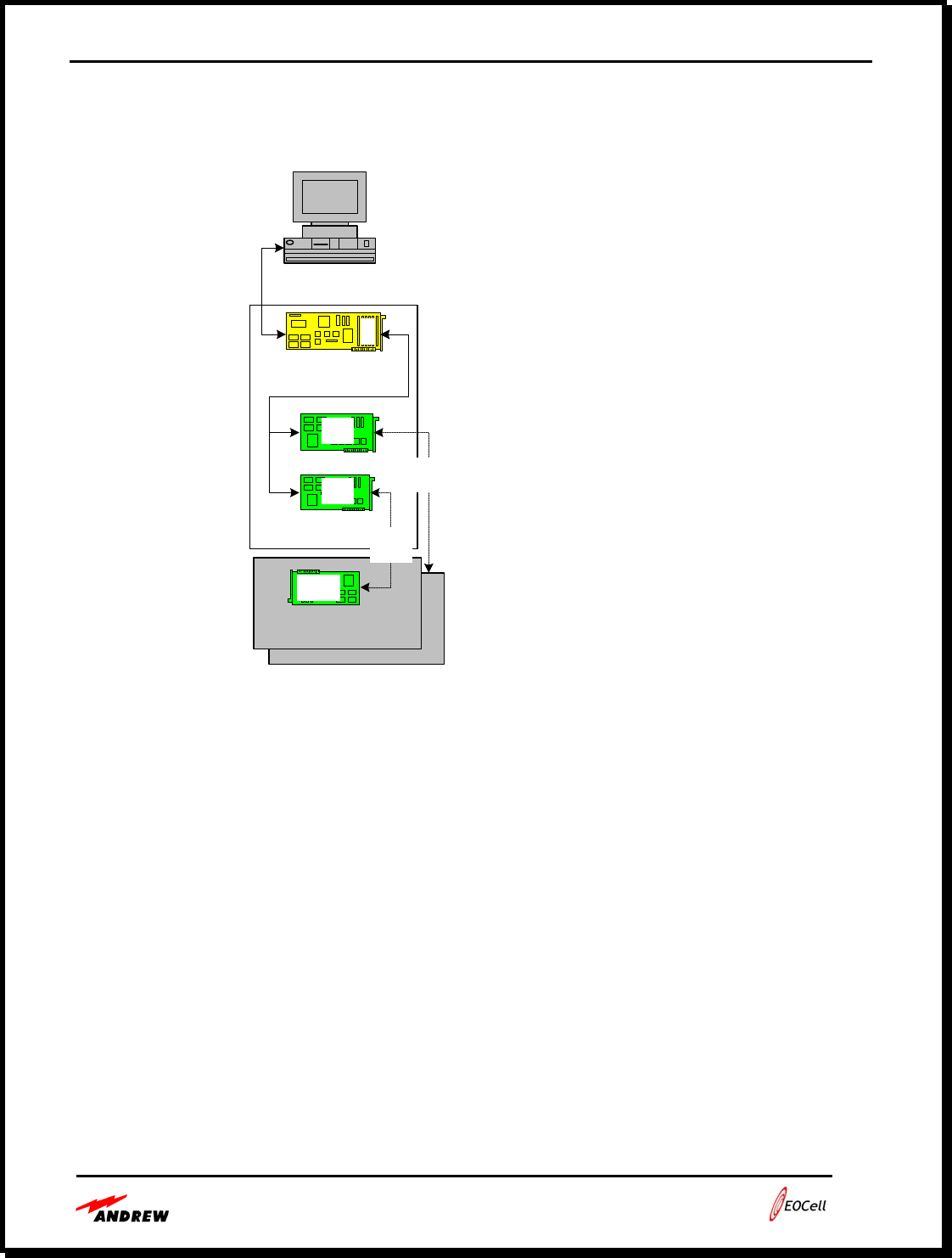
• System Level Message Flow
NMS Computer
Alarm Board
Transceivers Fiber
Optics
RS-232
Port 1
SPI
Bus
Local
1
1,1
1,2
Remote
Transceivers
1,20
Fiber
Optics
Alarm Board (1) is configured as an Alarm Controllers
Normal Operations Rules:
o Alarm board (1) polls the local transceivers [(1,1) (1,2)] on the SPI Bus and maintains
their status.
o Alarm board (1) also polls the remote transceivers [(1,10)(1,20)] and maintains their
status.

Users Guide - Andrew 2400 EOCell™ Fiber Optic Distributed Antenna System
5-10
• 16-Bit Check Sum algorithm
//Table to match NMS calculation
#define TABLE_SIZE 16
static const unsigned short uiCRCTable[TABLE_SIZE]=
{
0x0000,0x1081,0x2102,0x3183,0x4204,0x5285,0x6306,0x7387,
0x8408,0x9489,0xA50A,0xB58B,0xC60C,0xD68D,0xE70E,0xF78F
};
#define SHIFT_COUNT 4
unsigned int CRC_16(unsigned char *stringpointer,
unsigned char stringlength)
{
int nIndex;
unsigned char ucData;
unsigned int uiCRCValue;
uint8 *pData;
int i;

Users Guide - Andrew 2400 EOCell™ Fiber Optic Distributed Antenna System
5-11
// initialize to seed value
uiCRCValue = 0xffff;
pData = stringpointer;
//length is data bytes + address(2) + messageid(1) + data count(1)
for(i = 0; i < stringlength; ++i)
{
/* get the data byte */
ucData = *pData;
pData++;
/* get index into uiCRCTable using least significant nibble of data byte */
nIndex = (uiCRCValue ^ ucData) & 0x0F;
/* calculate new uiCRCValue using table value */
uiCRCValue = ((uiCRCValue >> SHIFT_COUNT) ^ uiCRCTable[nIndex]);
/* get index into uiCRCTable using most significant nibble of data byte */
nIndex = (uiCRCValue ^ (ucData >> SHIFT_COUNT)) & 0x0F;
/* calculate new uiCRCValue using table value */
uiCRCValue = ((uiCRCValue >> SHIFT_COUNT) ^ uiCRCTable[nIndex]);
}
return uiCRCValue;
}

Users Guide - Andrew 2400 EOCell™ Fiber Optic Distributed Antenna System
5-12
• List of Messages
Set System Address this command is used to change the system address of a component. An
address has two parts the Rack (first byte) and the Transceiver (second byte).
• Set System Command (0x83)
Command: 0x83
Byte count: 2 bytes
Data: (follows)
Items # bytes Description
Address: Rack 1 byte 1 to 254
Address: Transceiver 1 byte 1 to 254
• Set System Response (0x03)
Response: 0x03
Byte count: 1
Data: 0x00 ACK or 0x01 NACK

Users Guide - Andrew 2400 EOCell™ Fiber Optic Distributed Antenna System
5-13
Set Transceiver Table this command is used to build a Transceiver Table which contains both
the local and remote transceiver’s addresses for each transceiver pair. The alarm board uses the
transceiver table to route messages over the SPI Bus and Fiber optics. Unused Transceivers must
be filled with zeros (0).
• Set Transceiver Table Command (0x8A)
Command: 0x8A
Byte count: 32 bytes
Data: (follows)
Items # bytes Description
For each slot 1 to 8
Local Transceiver Addresses 2 Rack (1 - 254) + Transceiver (1 -254)
Remote Transceiver Addresses 2 Rack (1 - 254) + Transceiver (1 -254)
• Set Transceiver Table Response (0x0A)
Response: 0x0A
Byte count: 1
Data: 0x00 ACK or 0x01 NACK

Users Guide - Andrew 2400 EOCell™ Fiber Optic Distributed Antenna System
5-14
Get Alarm Board Detail Status this command retrieves the detail status of the Alarm Board,
located in the Master Rack. Alarms monitored on the Alarm Board are:
Power Supply (#1, #2) Present
DC FARM Module [of either Power Supply 1 or Power Supply 2 or both, if both are
installed]
AC/DC Converter Module [of either Power Supply 1 or Power Supply 2 or both, if
both are installed]
• Get Detail Status Command (0x92)
Command: 0x92
Data: None
• Get Detail Status Response (0x12)
Response: 0x12
Byte count: 35
Data: (see table below)
Items Byte No. Bit Definition Description
Temperature Status 1 1 –7 Not used.
8 0 = within –25 to +65°C,
1 = outside temperature range
Not Applicable 2 –6
1 0 = Power Supply #1 Present
1 = Module not present
2 0 = Power Supply #2 Present
1 = Module not present
7
3 – 8 Not used.
1 0 = PS#1: AC/DC Converter okay
1 = Module fail
2 0 = PS#1: DC/DC Regulator okay
1 = Module fail
3 0 = PS#2: AC/DC Converter okay
1 = Module fail
4 0 = PS#2: DC/DC Regulator okay
1 = Module fail
Power Supply Status
8
5 – 8 Not used.
Not Applicable 9 – 35

Users Guide - Andrew 2400 EOCell™ Fiber Optic Distributed Antenna System
5-15
Get Transceiver Status this command retrieves the current status of the Fiber Optic
Transceiver. Address determines which transceiver in the Master Rack, or which Remote fiber
transceiver is queried. Alarms monitored by the Fiber Transceivers include 8 internal alarms and
7 external alarms. External alarms are only used for reporting status of Remote Unit electronics.
• Get Transceiver Status Command (0xB1)
Command: 0xB1
Data: None
• Get Transceiver Status Response (0x31)
Response: 0x31
Bytes: 7
Data: (See table below)
Items Byte No. Bit Definition Description
Transceiver Slot
Number 1 1 – 8 The slot the transceiver occupies in the
Master Rack. Not applicable when used
with Remote Units.
Not Used 2
Transceiver External
Alarms #1 3 1 0 = AC Input Voltage okay
1 = AC input voltage low (fail)
(Applicable only to
Remote Units) 2 0 = 24 V Power Supply Module okay
1 = Module fail
3 0 = 12 V Power Supply Module okay
1 = Module fail
4 0 = Power Amplifier okay
1 = Amplifier fail
5 – 8 Not applicable
Not Used 4
Transceiver External 5 1 – 5 Not applicable
Alarms #2
(Applicable only to 6 0 = Low Noise Amplifier okay
1 = Amplifier fail
Remote Units) 7 Spare input
8 Spare input
Transceiver Internal
Alarms 6 1 0 = Transmit Amplifier okay
1 = Amplifier fail.

Users Guide - Andrew 2400 EOCell™ Fiber Optic Distributed Antenna System
5-16
2 0 = Laser Current okay
1 = Laser fail.
3 0 = Transmit FSK Level okay
1 = Transmit FSK fail
4 0 = FSK Receive Level okay
1 = Receive FSK fail
5 0 = Receive Amplifier 1 okay
1 = Amplifier fail
6 0 = Photo Diode Current okay
1 = Photo Diode fail
7 0 = Receive Amplifier 2 okay
1 = Amplifier fail
8 0 = FSK Amplifier okay
1 = Amplifier fail
Temperature Status 7 1 –7 Not used.
8 0 = within –25 to +65°C,
1 = outside temperature range

Users Guide - Andrew 2400 EOCell™ Fiber Optic Distributed Antenna System
6-1
Section 6:
Fiber Optic Cable Installation Guide
Note to Customers and Installers Page 6-2
EOCell Fiber Optic Cables Page 6-2
Installation Warnings Page 6-3
Testing Cables Page 6-3
Cleaning Connectors Page 6-3
Cable Installations Page 6-3
Installing Fiber Optic Connectors Page 6-4
Connecting Cables to Equipment Page 6-4

Users Guide - Andrew 2400 EOCell™ Fiber Optic Distributed Antenna System
6-2
• Note to Customers and Installers
This installation guide is to inform customers and installers of the special requirements for
installing the fiber optic cables used on the EOCell™ Distributed Antenna System (DAS).
This guide discusses several key items that customers and installers should be aware of
before starting the installation.
The fiber optic connector type used by the EOCell system and other high performance RF
over fiber systems are FC/APC. These are industry standard connector type typically used for
fiber optic networks. Customers doing the installation themselves or those hiring local fiber
optic cable installers to do the installation should take care in specifying these connectors and
installation requirements.
Correct fiber optic cable installation is very critical to the performance of an RF over fiber
system. In order to prevent system performance degradation, great care should be taken in
pulling and installing the fiber optic cables and connectors.
• EOCell Fiber Optic Cables
• The EOCell DAS can use standard duplex fiber optic cables to provide signals to and
from the RFFAU.
• The EOCell DAS uses single mode fiber optic cable for low loss, highest performance.
• EOCell uses FC/APC connectors for low back reflection. This connector type is
commonly used when sending high frequency RF signals over fiber and has higher
performance than standard FC type connectors.
• Plenum rated cables must be used in US buildings to meet fire safety codes.
• Andrew can provide cable assemblies’ cut to a customer specified length, assembled and
tested. Tested cable assemblies provide a low risk plug and play system connection. The
cable assemblies are typically used when the cable length is very well defined or when
the customer does not have fiber optic installation and measurement equipment. Andrew
recommends buying tested cable assemblies to avoid the many potential problems
encountered when doing field terminations of fiber optic cables.
• Duplex cable or cable assemblies can be bought from a wide range of vendors. Things to
specify are: single mode fiber, duplex cable, core size of 9/125, high quality FC/APC
connectors with a 125um hole size, plenum rated cable.
• Most cable vendors use a fiber optic cable color code where yellow outer jackets denote
single mode fiber cable and orange outer jackets are used for multimode fiber optic
cables. Ensure that only single mode fiber is used for the EOCell DAS.

Users Guide - Andrew 2400 EOCell™ Fiber Optic Distributed Antenna System
6-3
• Installation Warnings
• Damage! – Observe the minimum bend radius of the fiber optic cable. Ensure that the
cable is never bent beyond the specified bend radius. The cable may be permanently
degraded or may be weakened in a way that may cause failure later on.
• Damage! – Angled Physical Contact (APC) and Physical Contact (PC) connectors should
never be mated. This will result in permanent damage to both connectors and will also
result in significant signal degradation due to an air gap between connectors.
• Warning! – The lasers can cause severe eye damage. Do not look directly into any
active optical connector or fiber.
• Damage! – Do not use cable tie wraps to secure fiber optic cables as tight wraps can
cause microbends that weaken or break the optical cable and degrade performance. Also
avoid laying fiber optic cable on sharp corners or allowing the weight of the fiber optic
cable to pull the cable down onto a sharp corner.
• Testing Cables
• Testing cables requires a light source and an optical power meter. All test equipment
must have FC/APC connectors. If the test equipment does not have an FC/APC
connector, a high quality, low loss jumper cable with an FC/APC connector must be used
to interface the test equipment to the cable under test.
• An LED based light source used to test multimode fiber optic cables will not work. A
light source with a laser at 1310 nm wavelength must be used to test the single mode
fiber cables.
• Ensure that all connectors are cleaned properly as described in the cleaning section.
Calibrate out all losses between the laser light source and the power meter including all
adapter jumper cables.
• Cable assemblies provided by Andrew have been tested and are shipped with the cable
test data. If installing cable assemblies, making loss measurements of the cables before
installation is a good practice.
• Cleaning Connectors
Clean fiber optic connectors are very important for high performance system operation.
Always keep fiber dust covers on the ends of fiber cables and on the MFOTC and RFFAU.
Before installing cable into the equipment, always clean the connectors using the following
process:
• Use only 95% pure alcohol or ethanol to clean fiber optic connectors. The 95% pure
alcohol can be purchased behind the counter at most pharmacies.
• Use only lint free tissues dipped in the alcohol to clean the end of the fiber connector.
Dip the tissue in the alcohol and clean the connector end. Use dry air spray to dry the
connector end.

Users Guide - Andrew 2400 EOCell™ Fiber Optic Distributed Antenna System
6-4
• Cable Installation
• When pulling cables through buildings, always ensure that the cable is pulled through the
building with the stress on the rugged outer jacket of the cable, not on the ends.
• Warning - Damage can occur to connectorized cable assemblies if they are not protected
when being pulled. Damage will result in significant loss of performance.
• Pulling connectorized cables through buildings: Andrew has a fiber optic cable pulling
kit, AE04J-A0745, that is designed to pull fragile fiber optic cable assemblies through a
building without damaging the fiber or connectors. When the cable pulling kit
instructions are followed, the cable assemblies may be pulled through a building with the
stress on the rugged outer jacket of the cable.
• Installing Fiber Optic Connectors
• The EOCell uses FC/APC connectors to provide the low back reflection required for
sending RF signal over fiber optic cables. This document is not intended to detail the
connector installation process.
• Connecting Cables to Equipment
• Ensure that the fiber optic cable has proper cable strain relief so that the cable is not
stressed. While this may not cause a failure during installation, it may lead to potential
reliability problems later.
• Also verify that the cable is not bent over the minimum bend radius.
• Remove the dust caps from the cable connector and the equipment and clean the
connectors using pure (i.e. 95%) alcohol and a lint free towel as described in the cleaning
section above. Dry with dry compressed air.
• The RFFAU and the MFOTC have LED indicators to show if the optical link is correctly
operating. See the Table 5-1 for the LED indicators for the MFOTC and RFFAU.
• To avoid confusion and help in system debugging, it is often necessary to provide cable
markers on the cable ends to ensure that the correct cable is plugged into the correct
equipment plug. Cable marker kits for field marking are available from Panduit, part
number PLD-1, and Anixter, part number A000078386.