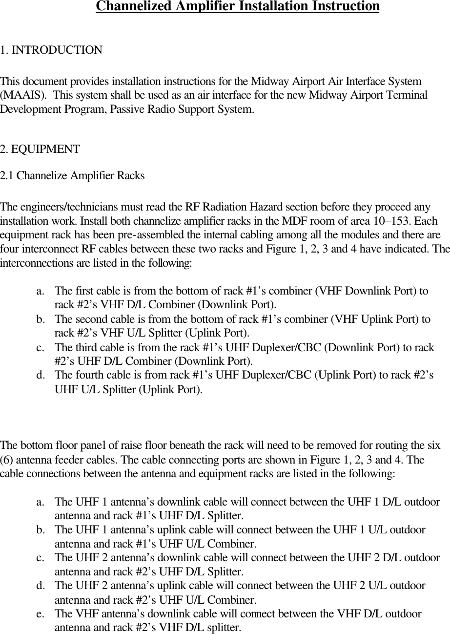
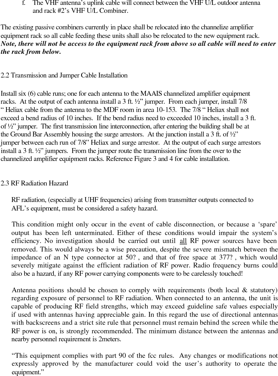
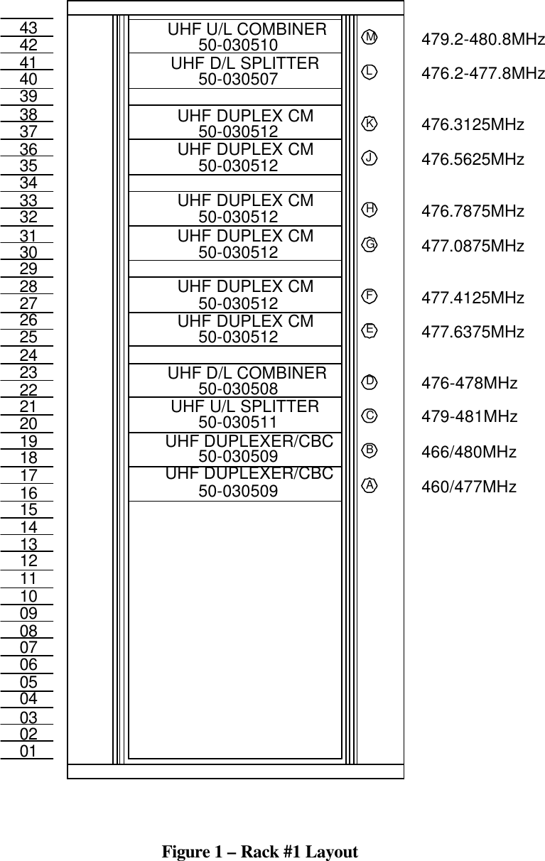
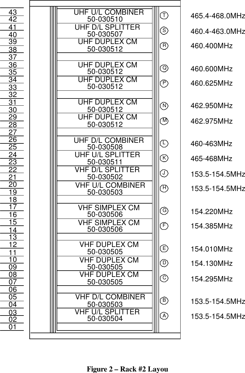
Andrew MAAIS Bi-Directional Amplifier User Manual Channelized Amplifier Installation Instruction

Andrew Corporation Bi-Directional Amplifier Channelized Amplifier Installation Instruction

Installation manual

Channelized Amplifier Installation Instruction  1. INTRODUCTION  This document provides installation instructions for the Midway Airport Air Interface System (MAAIS).  This system shall be used as an air interface for the new Midway Airport Terminal Development Program, Passive Radio Support System.    2. EQUIPMENT  2.1 Channelize Amplifier Racks  The engineers/technicians must read the RF Radiation Hazard section before they proceed any installation work. Install both channelize amplifier racks in the MDF room of area 10–153. Each equipment rack has been pre-assembled the internal cabling among all the modules and there are four interconnect RF cables between these two racks and Figure 1, 2, 3 and 4 have indicated. The interconnections are listed in the following:  a. The first cable is from the bottom of rack #1’s combiner (VHF Downlink Port) to rack #2’s VHF D/L Combiner (Downlink Port).     b.  The second cable is from the bottom of rack #1’s combiner (VHF Uplink Port) to rack #2’s VHF U/L Splitter (Uplink Port). c. The third cable is from the rack #1’s UHF Duplexer/CBC (Downlink Port) to rack #2’s UHF D/L Combiner (Downlink Port). d.  The fourth cable is from rack #1’s UHF Duplexer/CBC (Uplink Port) to rack #2’s UHF U/L Splitter (Uplink Port).     The bottom floor panel of raise floor beneath the rack will need to be removed for routing the six (6) antenna feeder cables. The cable connecting ports are shown in Figure 1, 2, 3 and 4. The cable connections between the antenna and equipment racks are listed in the following:  a. The UHF 1 antenna’s downlink cable will connect between the UHF 1 D/L outdoor antenna and rack #1’s UHF D/L Splitter. b.  The UHF 1 antenna’s uplink cable will connect between the UHF 1 U/L outdoor antenna and rack #1’s UHF U/L Combiner. c. The UHF 2 antenna’s downlink cable will connect between the UHF 2 D/L outdoor antenna and rack #2’s UHF D/L Splitter. d.  The UHF 2 antenna’s uplink cable will connect between the UHF 2 U/L outdoor antenna and rack #2’s UHF U/L Combiner. e. The VHF antenna’s downlink cable will connect between the VHF D/L outdoor antenna and rack #2’s VHF D/L splitter.
f. The VHF antenna’s uplink cable will connect between the VHF U/L outdoor antenna and rack #2’s VHF U/L Combiner.  The existing passive combiners currently in place shall be relocated into the channelize amplifier equipment rack so all cable feeding these units shall also be relocated to the new equipment rack. Note, there will not be access to the equipment rack from above so all cable will need to enter the rack from below.  2.2 Transmission and Jumper Cable Installation  Install six (6) cable runs; one for each antenna to the MAAIS channelized amplifier equipment racks.  At the output of each antenna install a 3 ft. ½” jumper.  From each jumper, install 7/8 “ Heliax cable from the antenna to the MDF room in area 10-153.  The 7/8 “ Heliax shall not exceed a bend radius of 10 inches.  If the bend radius need to exceeded 10 inches, install a 3 ft. of ½” jumper.  The first transmission line interconnection, after entering the building shall be at the Ground Bar Assembly housing the surge arrestors.  At the junction install a 3 ft. of ½” jumper between each run of 7/8” Heliax and surge arrestor.  At the output of each surge arrestors install a 3 ft. ½” jumpers.  From the jumper route the transmission line from the over to the channelized amplifier equipment racks. Reference Figure 3 and 4 for cable installation.     2.3 RF Radiation Hazard  RF radiation, (especially at UHF frequencies) arising from transmitter outputs connected to AFL’s equipment, must be considered a safety hazard.  This condition might only occur in the event of cable disconnection, or because a ‘spare’ output has been left unterminated. Either of these conditions would impair the system’s efficiency. No investigation should  be carried out until  all RF power sources have been removed. This would always be a wise precaution, despite the severe mismatch between the impedance of an N type connector at 50?, and that of free space at 377?, which would severely mitigate against the efficient radiation of RF power. Radio frequency burns could also be a hazard, if any RF power carrying components were to be carelessly touched!  Antenna positions should be chosen to comply with requirements (both local & statutory) regarding exposure of personnel to RF radiation. When connected to an antenna, the unit is capable of producing RF field strengths, which may exceed guideline safe values especially if used with antennas having appreciable gain. In this regard the use of directional antennas with backscreens and a strict site rule that personnel must remain behind the screen while the RF power is on, is strongly recommended. The minimum distance between the antennas and nearby personnel requirement is 2meters.  “This equipment complies with part 90 of the fcc rules.  Any changes or modifications not expressly approved by the manufacturer could void the user’s authority to operate the equipment.”
 Where the equipment is used near power lines, or in association with temporary masts not having lightning protection, the use of a safety earth connected to the case-earthing bolt is strongly advised.
           05020304011006070809121314151136261716181920222324252131272829303233343540373839424143UHF DUPLEXER/CBC50-03050950-030509UHF DUPLEXER/CBC50-030511UHF U/L SPLITTER50-030508UHF D/L COMBINER50-030512UHF DUPLEX CM50-030512UHF DUPLEX CM50-030512UHF DUPLEX CM50-030512UHF DUPLEX CM50-030512UHF DUPLEX CM50-030512UHF DUPLEX CM50-030507UHF D/L SPLITTER50-030510UHF U/L COMBINERABCDEFGHJKLM460/477MHz466/480MHz479-481MHz476-478MHz477.6375MHz477.4125MHz477.0875MHz476.7875MHz476.5625MHz476.3125MHz476.2-477.8MHz479.2-480.8MHz Figure 1 – Rack #1 Layout
05020304011006070809121314151136261716181920222324252131272829303233343540373839424143VHF U/L SPLITTER50-03050450-030503VHF D/L COMBINER50-030505VHF DUPLEX CM50-030505VHF DUPLEX CM50-030505VHF DUPLEX CM50-030506VHF SIMPLEX CM50-030506VHF SIMPLEX CMVHF U/L COMBINER50-030503VHF D/L SPLITTER50-030502UHF U/L SPLITTER50-030511UHF D/L COMBINER50-030508UHF DUPLEX CM50-03051250-030512UHF DUPLEX CM50-030512UHF DUPLEX CM50-030512UHF DUPLEX CM50-030512UHF DUPLEX CM50-030507UHF D/L SPLITTERUHF U/L COMBINER50-030510153.5-154.5MHzAB153.5-154.5MHzC154.295MHzD154.130MHzE154.010MHzF154.385MHzG154.220MHzH153.5-154.5MHzJ153.5-154.5MHzK465-468MHzL460-463MHzM462.975MHzN462.950MHzP460.625MHzQ460.600MHzR460.400MHzS460.4-463.0MHzT465.4-468.0MHz  Figure 2 – Rack #2 Layou
05020304011006070809121314151136261716181920222324252131272829303233343540373839424143D/LU2 U/LU2U/LUHF1 D/LUHF1LCX LCXVHF D/LVHF U/LDN UPGrounding Bar7/8" Cable1/2" jumper1/2" jumper  Figure 3 – Cable Connection for Rack # 2
05020304011006070809121314151136261716181920222324252131272829303233343540373839424143VU/L D/LVU/LU1D/LU1U/LUHF2D/LUHF2D/LVHFU/LVHFGrounding Bar7/8" Cable7/8" Cable1/2" jumper1/2" jumper1/2" jumper1/2" jumperOutdoor Antennas  Figure 4 – Cable Connection for Rack # 2

Navigation menu