Andrew MAAIS Bi-Directional Amplifier User Manual Channelized Amplifier Installation Instruction
Andrew Corporation Bi-Directional Amplifier Channelized Amplifier Installation Instruction
Andrew >
Installation manual

Channelized Amplifier Installation Instruction
1. INTRODUCTION
This document provides installation instructions for the Midway Airport Air Interface System
(MAAIS). This system shall be used as an air interface for the new Midway Airport Terminal
Development Program, Passive Radio Support System.
2. EQUIPMENT
2.1 Channelize Amplifier Racks
The engineers/technicians must read the RF Radiation Hazard section before they proceed any
installation work. Install both channelize amplifier racks in the MDF room of area 10–153. Each
equipment rack has been pre-assembled the internal cabling among all the modules and there are
four interconnect RF cables between these two racks and Figure 1, 2, 3 and 4 have indicated. The
interconnections are listed in the following:
a. The first cable is from the bottom of rack #1’s combiner (VHF Downlink Port) to
rack #2’s VHF D/L Combiner (Downlink Port).
b. The second cable is from the bottom of rack #1’s combiner (VHF Uplink Port) to
rack #2’s VHF U/L Splitter (Uplink Port).
c. The third cable is from the rack #1’s UHF Duplexer/CBC (Downlink Port) to rack
#2’s UHF D/L Combiner (Downlink Port).
d. The fourth cable is from rack #1’s UHF Duplexer/CBC (Uplink Port) to rack #2’s
UHF U/L Splitter (Uplink Port).
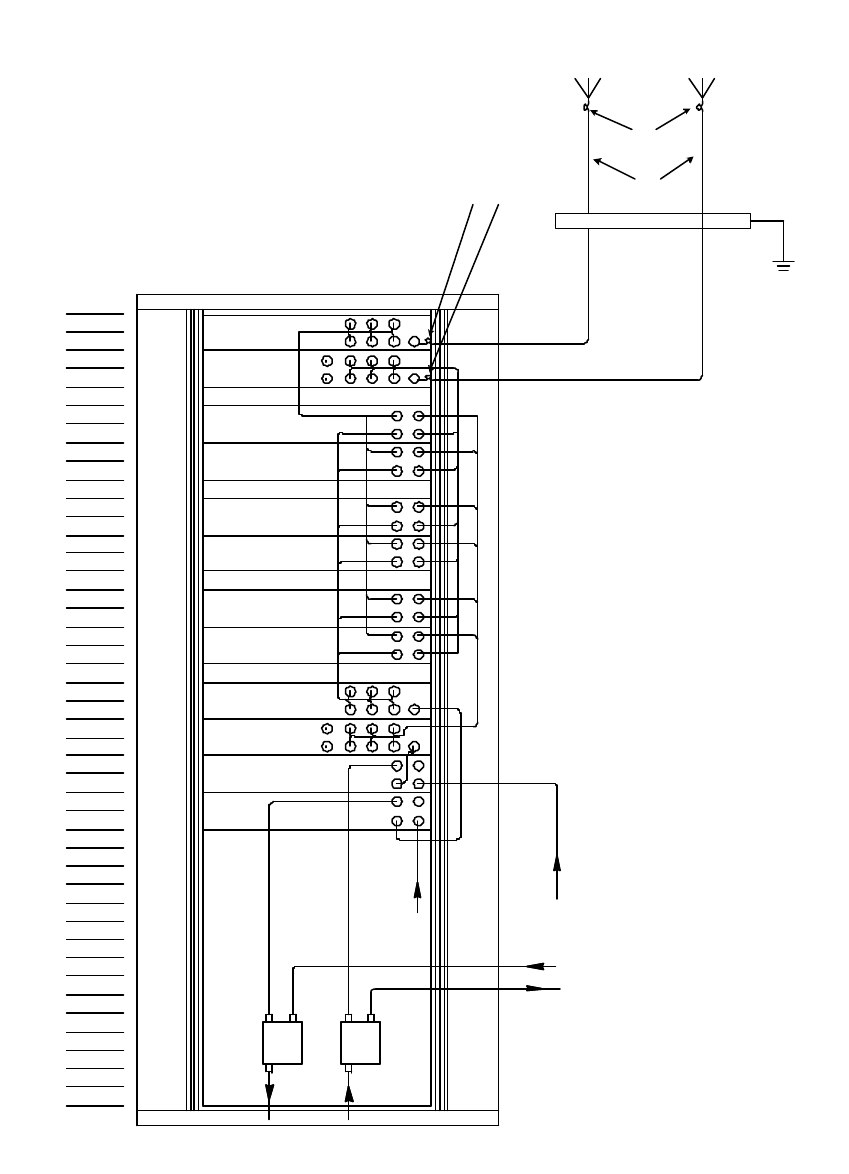
The bottom floor panel of raise floor beneath the rack will need to be removed for routing the six
(6) antenna feeder cables. The cable connecting ports are shown in Figure 1, 2, 3 and 4. The
cable connections between the antenna and equipment racks are listed in the following:
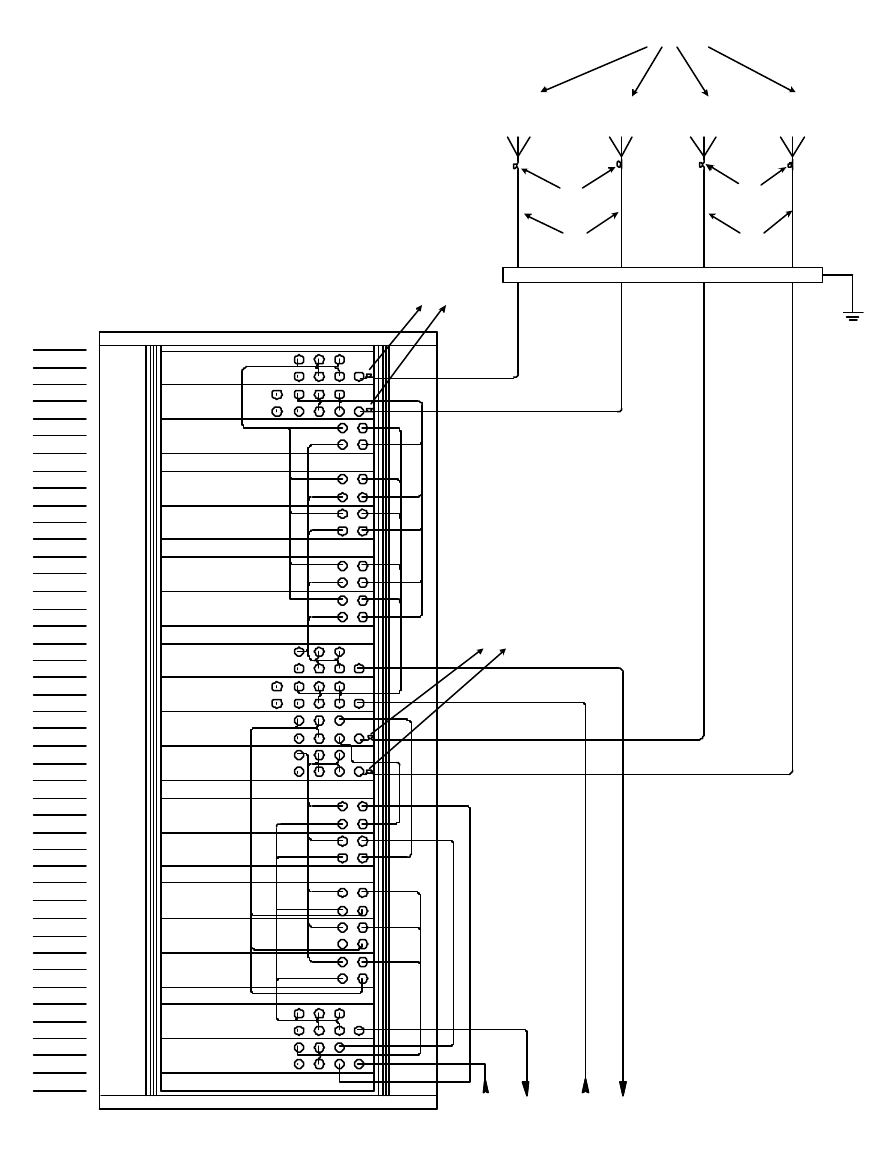
a. The UHF 1 antenna’s downlink cable will connect between the UHF 1 D/L outdoor
antenna and rack #1’s UHF D/L Splitter.
b. The UHF 1 antenna’s uplink cable will connect between the UHF 1 U/L outdoor
antenna and rack #1’s UHF U/L Combiner.
c. The UHF 2 antenna’s downlink cable will connect between the UHF 2 D/L outdoor
antenna and rack #2’s UHF D/L Splitter.
d. The UHF 2 antenna’s uplink cable will connect between the UHF 2 U/L outdoor
antenna and rack #2’s UHF U/L Combiner.
e. The VHF antenna’s downlink cable will connect between the VHF D/L outdoor
antenna and rack #2’s VHF D/L splitter.

f. The VHF antenna’s uplink cable will connect between the VHF U/L outdoor antenna
and rack #2’s VHF U/L Combiner.
The existing passive combiners currently in place shall be relocated into the channelize amplifier
equipment rack so all cable feeding these units shall also be relocated to the new equipment rack.
Note, there will not be access to the equipment rack from above so all cable will need to enter
the rack from below.
2.2 Transmission and Jumper Cable Installation
Install six (6) cable runs; one for each antenna to the MAAIS channelized amplifier equipment
racks. At the output of each antenna install a 3 ft. ½” jumper. From each jumper, install 7/8
“ Heliax cable from the antenna to the MDF room in area 10-153. The 7/8 “ Heliax shall not
exceed a bend radius of 10 inches. If the bend radius need to exceeded 10 inches, install a 3 ft.
of ½” jumper. The first transmission line interconnection, after entering the building shall be at
the Ground Bar Assembly housing the surge arrestors. At the junction install a 3 ft. of ½”
jumper between each run of 7/8” Heliax and surge arrestor. At the output of each surge arrestors
install a 3 ft. ½” jumpers. From the jumper route the transmission line from the over to the
channelized amplifier equipment racks. Reference Figure 3 and 4 for cable installation.
2.3 RF Radiation Hazard
RF radiation, (especially at UHF frequencies) arising from transmitter outputs connected to
AFL’s equipment, must be considered a safety hazard.
This condition might only occur in the event of cable disconnection, or because a ‘spare’
output has been left unterminated. Either of these conditions would impair the system’s
efficiency. No investigation should be carried out until all RF power sources have been
removed. This would always be a wise precaution, despite the severe mismatch between the
impedance of an N type connector at 50?, and that of free space at 377?, which would
severely mitigate against the efficient radiation of RF power. Radio frequency burns could
also be a hazard, if any RF power carrying components were to be carelessly touched!
Antenna positions should be chosen to comply with requirements (both local & statutory)
regarding exposure of personnel to RF radiation. When connected to an antenna, the unit is
capable of producing RF field strengths, which may exceed guideline safe values especially
if used with antennas having appreciable gain. In this regard the use of directional antennas
with backscreens and a strict site rule that personnel must remain behind the screen while the
RF power is on, is strongly recommended. The minimum distance between the antennas and
nearby personnel requirement is 2meters.
“This equipment complies with part 90 of the fcc rules. Any changes or modifications not
expressly approved by the manufacturer could void the user’s authority to operate the
equipment.”
Where the equipment is used near power lines, or in association with temporary masts not
having lightning protection, the use of a safety earth connected to the case-earthing bolt is
strongly advised.
05
02
03
04
01
10
06
07
08
09
12
13
14
15
11
36
26
17
16
18
19
20
22
23
24
25
21
31
27
28
29
30
32
33
34
35
40
37
38
39
42
41
43
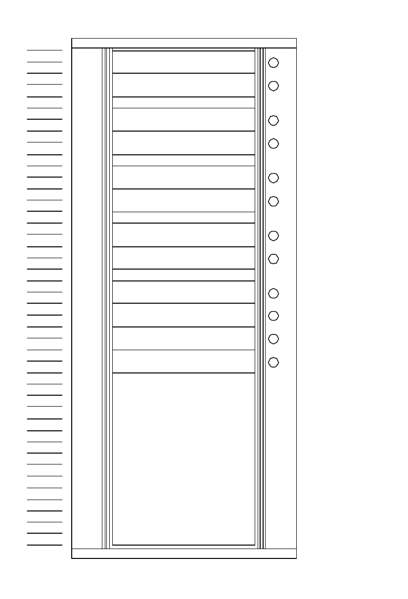
UHF DUPLEXER/CBC
50-030509
50-030509
UHF DUPLEXER/CBC
50-030511
UHF U/L SPLITTER
50-030508
UHF D/L COMBINER
50-030512
UHF DUPLEX CM
50-030512
UHF DUPLEX CM
50-030512
UHF DUPLEX CM
50-030512
UHF DUPLEX CM
50-030512
UHF DUPLEX CM
50-030512
UHF DUPLEX CM
50-030507
UHF D/L SPLITTER
50-030510
UHF U/L COMBINER
A
B
C
D
E
F
G
H
J
K
L
M
460/477MHz
466/480MHz
479-481MHz
476-478MHz
477.6375MHz
477.4125MHz
477.0875MHz
476.7875MHz
476.5625MHz
476.3125MHz
476.2-477.8MHz
479.2-480.8MHz
Figure 1 – Rack #1 Layout
05
02
03
04
01
10
06
07
08
09
12
13
14
15
11
36
26
17
16
18
19
20
22
23
24
25
21
31
27
28
29
30
32
33
34
35
40
37
38
39
42
41
43
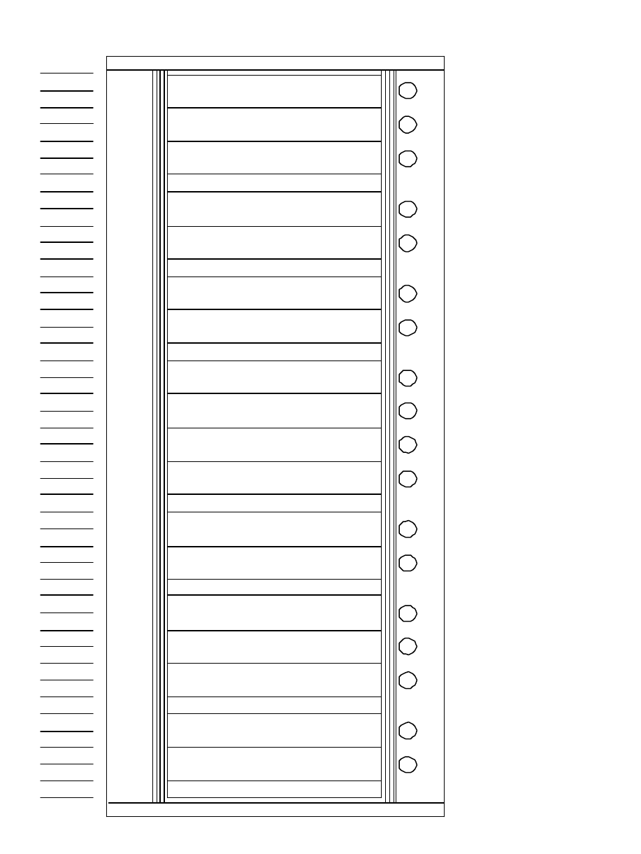
VHF U/L SPLITTER
50-030504
50-030503
VHF D/L COMBINER
50-030505
VHF DUPLEX CM
50-030505
VHF DUPLEX CM
50-030505
VHF DUPLEX CM
50-030506
VHF SIMPLEX CM
50-030506
VHF SIMPLEX CM
VHF U/L COMBINER
50-030503
VHF D/L SPLITTER
50-030502
UHF U/L SPLITTER
50-030511
UHF D/L COMBINER
50-030508
UHF DUPLEX CM
50-030512
50-030512
UHF DUPLEX CM
50-030512
UHF DUPLEX CM
50-030512
UHF DUPLEX CM
50-030512
UHF DUPLEX CM
50-030507
UHF D/L SPLITTER
UHF U/L COMBINER
50-030510
153.5-154.5MHz
A
B153.5-154.5MHz
C154.295MHz
D154.130MHz
E154.010MHz
F154.385MHz
G154.220MHz
H153.5-154.5MHz
J153.5-154.5MHz
K465-468MHz
L460-463MHz
M462.975MHz
N462.950MHz
P460.625MHz
Q460.600MHz
R460.400MHz
S460.4-463.0MHz
T465.4-468.0MHz
Figure 2 – Rack #2 Layou
05
02
03
04
01
10
06
07
08
09
12
13
14
15
11
36
26
17
16
18
19
20
22
23
24
25
21
31
27
28
29
30
32
33
34
35
40
37
38
39
42
41
43
D/L
U2 U/L
U2
U/L
UHF1 D/L
UHF1
LCX LCX
VHF D/L
VHF U/L
DN UP
Grounding Bar
7/8" Cable
1/2" jumper
1/2" jumper
Figure 3 – Cable Connection for Rack # 2
05
02
03
04
01
10
06
07
08
09
12
13
14
15
11
36
26
17
16
18
19
20
22
23
24
25
21
31
27
28
29
30
32
33
34
35
40
37
38
39
42
41
43
V
U/L D/L
V
U/L
U1
D/L
U1
U/L
UHF2
D/L
UHF2
D/L
VHF
U/L
VHF
Grounding Bar
7/8" Cable7/8" Cable
1/2" jumper
1/2" jumper
1/2" jumper
1/2" jumper
Outdoor Antennas
Figure 4 – Cable Connection for Rack # 2