Andrew MDL2400BDR Base Station Data Radio User Manual Operation and Maintenance Line Amp
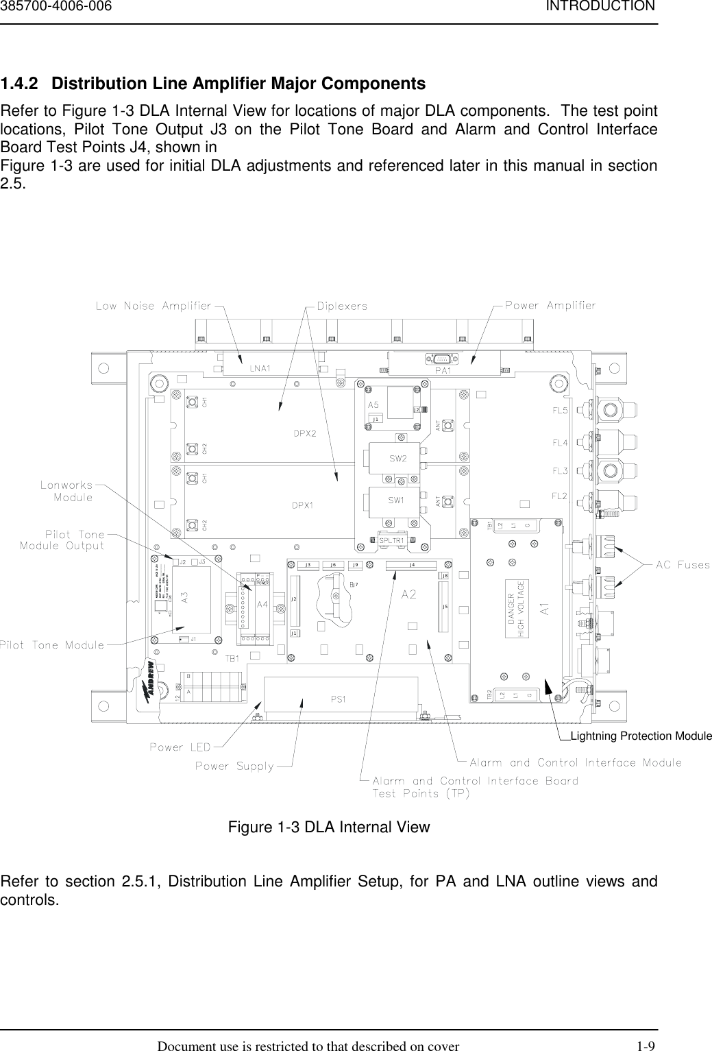
Andrew Corporation Base Station Data Radio Operation and Maintenance Line Amp
Andrew >
Contents
- 1. Operation and Maintenance BDR
- 2. Operation and Maintenance Line Amp
- 3. user manual
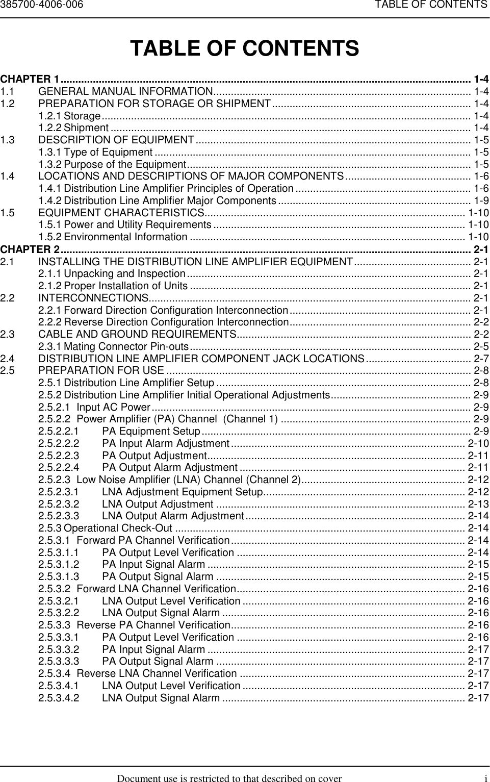
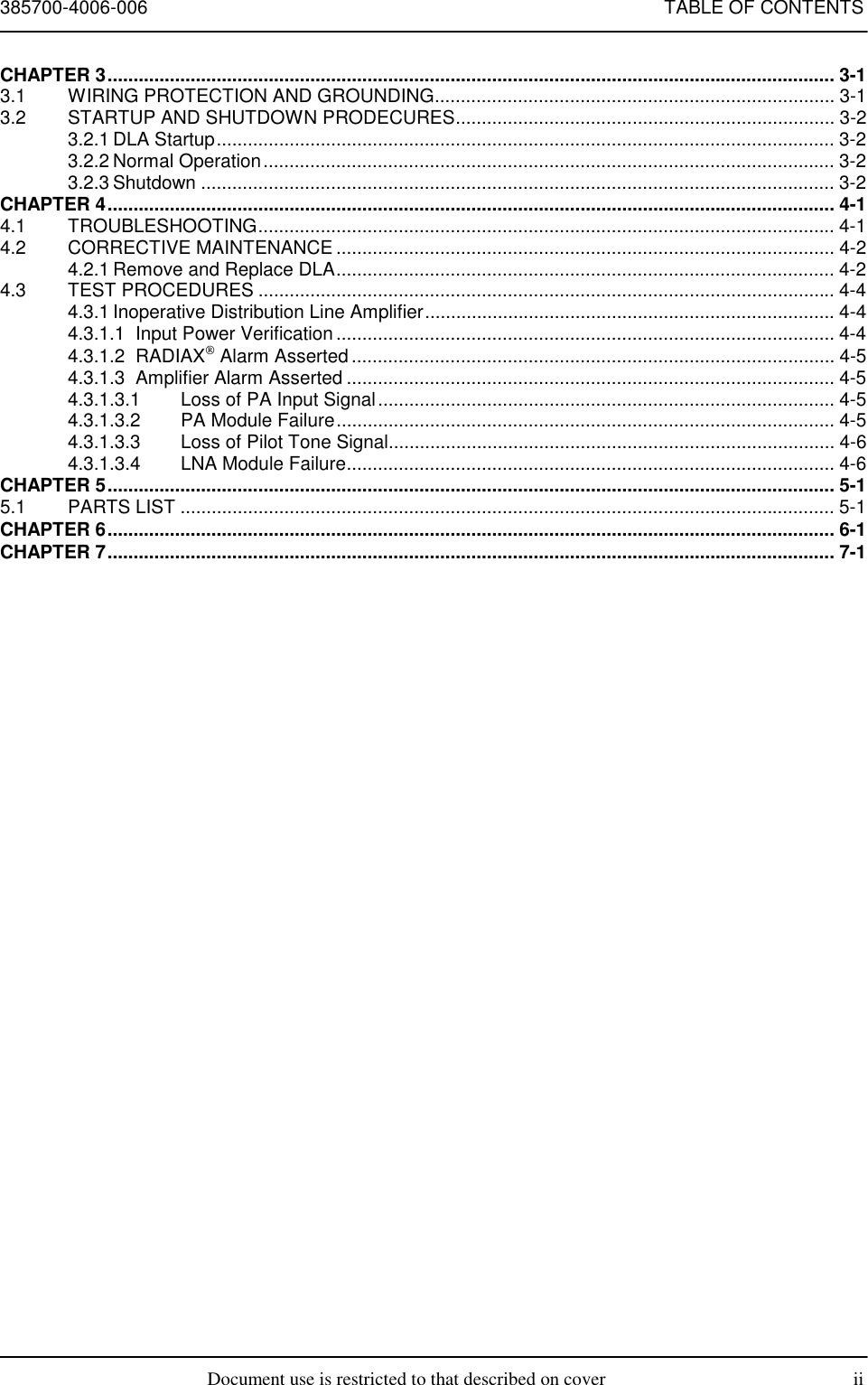
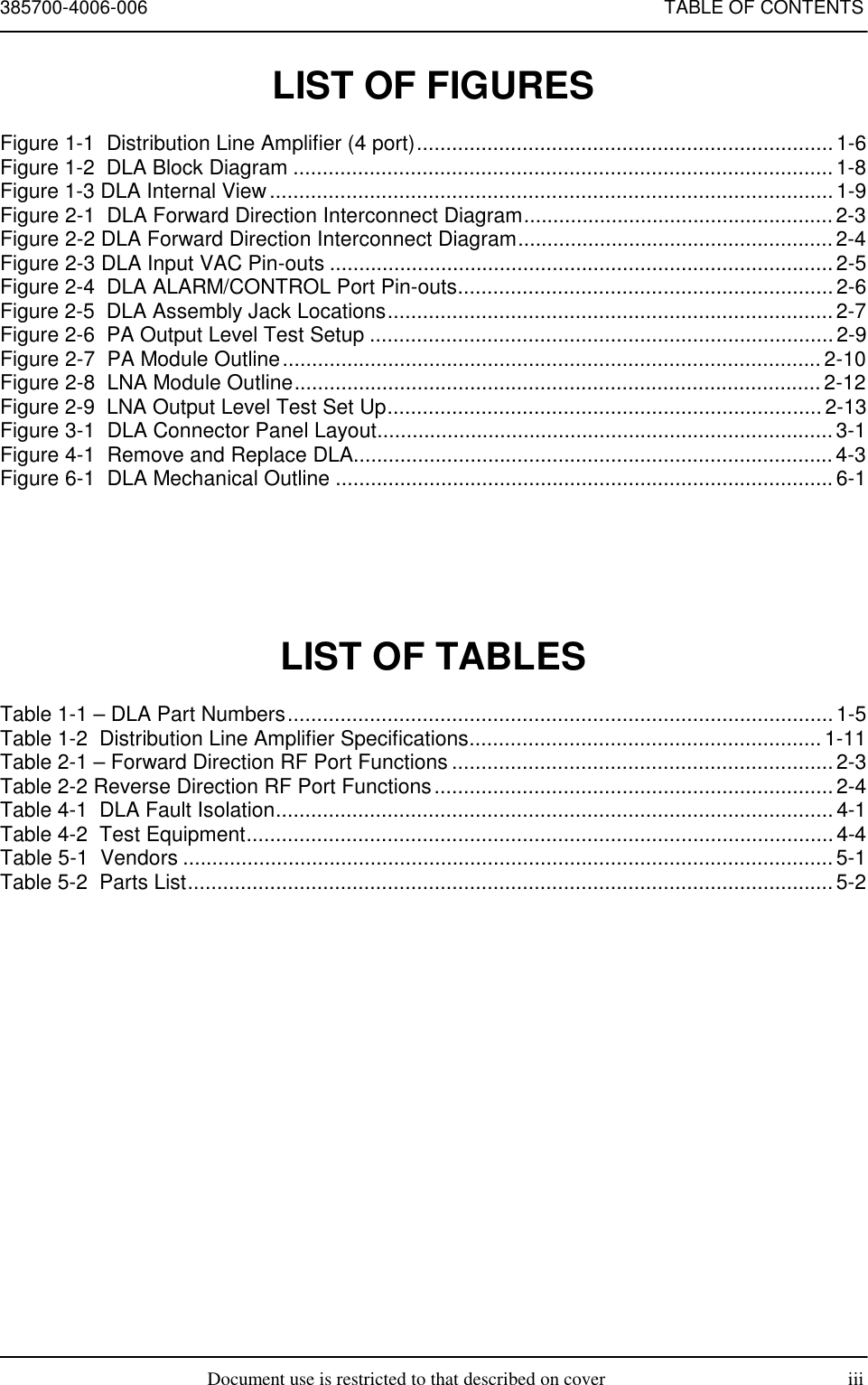
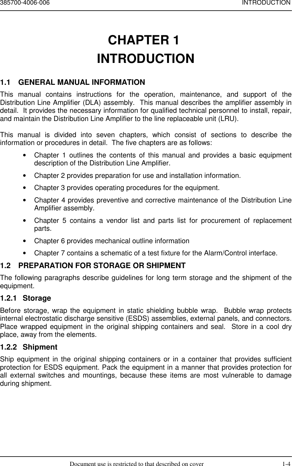
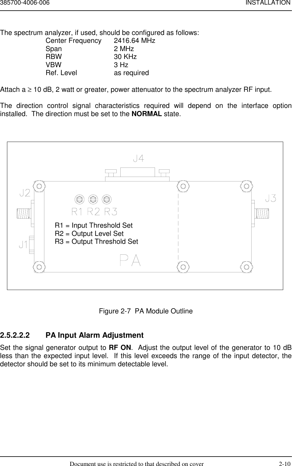
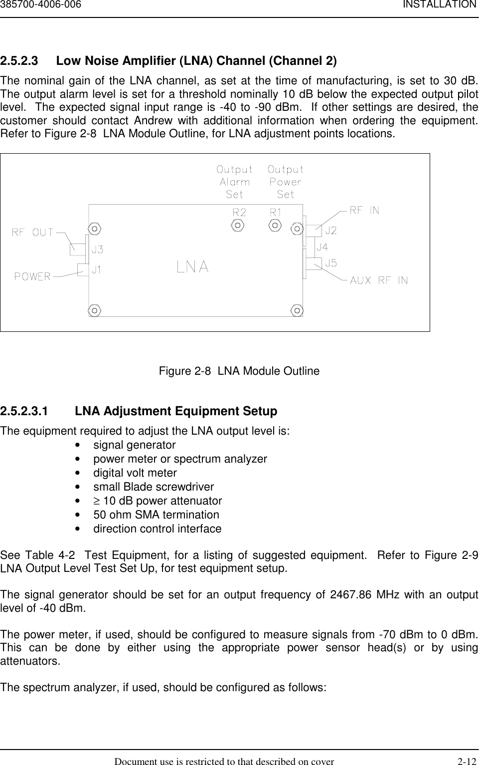
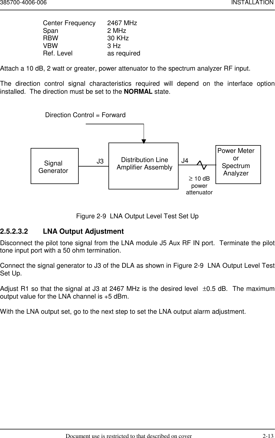
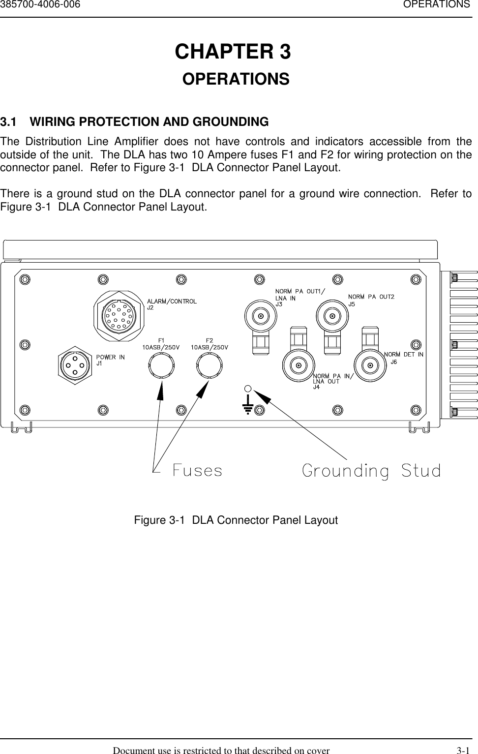
Operation and Maintenance Line Amp