Andrew MDL2400BDR Base Station Data Radio User Manual Operation and Maintenance Line Amp
Andrew Corporation Base Station Data Radio Operation and Maintenance Line Amp
Andrew >
Contents
- 1. Operation and Maintenance BDR
- 2. Operation and Maintenance Line Amp
- 3. user manual
Operation and Maintenance Line Amp

OPERATION AND MAINTENANCE MANUAL
For the
MODEL 2400
DISTRIBUTION LINE AMPLIFIER
MANUAL NO. 385700-4006
REVISION 6
The information set forth in this document and all rights in and to inventions
disclosed herein, and patents which might be granted thereon disclosing,
employing or covering the materials, methods, techniques or apparatus
described herein are the exclusive property of Andrew Corporation.
This document is an operation and maintenance manual. No disclosure or
reproduction of the information or drawings shall be made of any other
purpose without the prior written consent of Andrew. Use of the information
contained herein to fabricate or assemble any item in whole or in part is
expressly prohibited.
2601 Telecom Parkway, Richardson, Texas 75082-3521
TEL (972) 952 9700 FAX (972) 952-0000

385700-4006-006 SAFETY SUMMARY
Document use is restricted to that described on cover A
SAFETY SUMMARY
High voltage is used in the operation of
this equipment. Death on contact may
result, if personnel fail to observe the
following safety precautions:
• Do not be misled by the term “Low Voltage.” Potentials as low as 50 Volts may cause
death under adverse conditions.
• Do not crush, puncture, disassemble or otherwise mutilate batteries. Leaking batteries
can cause serious damage to equipment and injury to personnel.
• Do not remove covers or access plates on the equipment, unless you are authorized to do so.
• Do not work on electronic equipment unless there is another person nearby who is familiar
with the operation of the equipment and is trained in administering first aid.
• Whenever possible, disconnect the equipment from the power source before beginning
maintenance.
• To prevent electrical shock or damage to the equipment, do not operate it until you
thoroughly understand the operation and function of all controls, indicators, and
connectors.
• Turn off all power to the equipment before replacing any fuses.
FIRST AID
In case of electrical shock:
• Do not try to pull or grab the individual.
• If possible, turn off the electrical power.
• If you cannot turn off the electrical power, pull, push, or lift the person to safety using a dry
wooden pole, a dry rope, or some other insulating material.
• Send for help as soon as possible.
• After the injured person is no longer in contact with the source of electrical shock, move
the person a short distance away and immediately administer first aid and artificial
resuscitation as required.
385700-4006-006 LIST OF ABBREVIATIONS AND ACRONYMS
Document use is restricted to that described on cover B
The Distribution Line Amplifier is an unlicensed device operating
under the conditions of FCC part 15 regulations. This equipment
is intended to be installed and operated by professional parties.
It is the responsibility of those parties to insure that the
equipment is operated in compliance with the applicable FCC
part 15 specifications.
LIST OF ABBREVIATIONS AND ACRONYMS
All abbreviations/acronyms used in this
manual, other than those listed on this
page, are used per MIL-STD-12D.
BDR Base Data Radio
USER Communications-Based Train Control
DLA Distribution Line Amplifier
ESDS Electrostatic Discharge Sensitive
FWD Forward
LRU Line Replaceable Unit
MDR Mobile Data Radio
PC Personal Computer
RCS Radio Communication Subsystem
RF Radio Frequency
RVS Reverse
SSR Spread Spectrum Radio
N
O
TE
WARNING

385700-4006-006 LIST OF REFERENCE DOCUMENTS
Document use is restricted to that described on cover C
LIST OF REFERENCE DOCUMENTS
Andrew Catalog 37 (or latest version)
Drawings:
Assembly, Line Amplifier 385700-4000

385700-4006-006 TABLE OF CONTENTS
Document use is restricted to that described on cover i
TABLE OF CONTENTS
CHAPTER 1............................................................................................................................................ 1-4
1.1 GENERAL MANUAL INFORMATION........................................................................................ 1-4
1.2 PREPARATION FOR STORAGE OR SHIPMENT.................................................................... 1-4
1.2.1 Storage.............................................................................................................................. 1-4
1.2.2 Shipment ........................................................................................................................... 1-4
1.3 DESCRIPTION OF EQUIPMENT.............................................................................................. 1-5
1.3.1 Type of Equipment ............................................................................................................ 1-5
1.3.2 Purpose of the Equipment................................................................................................. 1-5
1.4 LOCATIONS AND DESCRIPTIONS OF MAJOR COMPONENTS........................................... 1-6
1.4.1 Distribution Line Amplifier Principles of Operation ............................................................ 1-6
1.4.2 Distribution Line Amplifier Major Components.................................................................. 1-9
1.5 EQUIPMENT CHARACTERISTICS......................................................................................... 1-10
1.5.1 Power and Utility Requirements ...................................................................................... 1-10
1.5.2 Environmental Information .............................................................................................. 1-10
CHAPTER 2............................................................................................................................................ 2-1
2.1 INSTALLING THE DISTRIBUTION LINE AMPLIFIER EQUIPMENT........................................ 2-1
2.1.1 Unpacking and Inspection................................................................................................. 2-1
2.1.2 Proper Installation of Units ................................................................................................ 2-1
2.2 INTERCONNECTIONS.............................................................................................................. 2-1
2.2.1 Forward Direction Configuration Interconnection.............................................................. 2-1
2.2.2 Reverse Direction Configuration Interconnection.............................................................. 2-2
2.3 CABLE AND GROUND REQUIREMENTS................................................................................ 2-2
2.3.1 Mating Connector Pin-outs................................................................................................ 2-5
2.4 DISTRIBUTION LINE AMPLIFIER COMPONENT JACK LOCATIONS.................................... 2-7
2.5 PREPARATION FOR USE ........................................................................................................ 2-8
2.5.1 Distribution Line Amplifier Setup ....................................................................................... 2-8
2.5.2 Distribution Line Amplifier Initial Operational Adjustments................................................ 2-9
2.5.2.1 Input AC Power............................................................................................................. 2-9
2.5.2.2 Power Amplifier (PA) Channel (Channel 1) ................................................................. 2-9
2.5.2.2.1 PA Equipment Setup............................................................................................ 2-9
2.5.2.2.2 PA Input Alarm Adjustment................................................................................ 2-10
2.5.2.2.3 PA Output Adjustment........................................................................................ 2-11
2.5.2.2.4 PA Output Alarm Adjustment ............................................................................. 2-11
2.5.2.3 Low Noise Amplifier (LNA) Channel (Channel 2)........................................................ 2-12
2.5.2.3.1 LNA Adjustment Equipment Setup..................................................................... 2-12
2.5.2.3.2 LNA Output Adjustment ..................................................................................... 2-13
2.5.2.3.3 LNA Output Alarm Adjustment........................................................................... 2-14
2.5.3 Operational Check-Out ................................................................................................... 2-14
2.5.3.1 Forward PA Channel Verification................................................................................ 2-14
2.5.3.1.1 PA Output Level Verification .............................................................................. 2-14
2.5.3.1.2 PA Input Signal Alarm ........................................................................................ 2-15
2.5.3.1.3 PA Output Signal Alarm ..................................................................................... 2-15
2.5.3.2 Forward LNA Channel Verification.............................................................................. 2-16
2.5.3.2.1 LNA Output Level Verification ............................................................................ 2-16
2.5.3.2.2 LNA Output Signal Alarm ................................................................................... 2-16
2.5.3.3 Reverse PA Channel Verification................................................................................ 2-16
2.5.3.3.1 PA Output Level Verification .............................................................................. 2-16
2.5.3.3.2 PA Input Signal Alarm ........................................................................................ 2-17
2.5.3.3.3 PA Output Signal Alarm ..................................................................................... 2-17
2.5.3.4 Reverse LNA Channel Verification ............................................................................. 2-17
2.5.3.4.1 LNA Output Level Verification ............................................................................ 2-17
2.5.3.4.2 LNA Output Signal Alarm ................................................................................... 2-17

385700-4006-006 TABLE OF CONTENTS
Document use is restricted to that described on cover ii
CHAPTER 3............................................................................................................................................ 3-1
3.1 WIRING PROTECTION AND GROUNDING............................................................................. 3-1
3.2 STARTUP AND SHUTDOWN PRODECURES......................................................................... 3-2
3.2.1 DLA Startup....................................................................................................................... 3-2
3.2.2 Normal Operation.............................................................................................................. 3-2
3.2.3 Shutdown .......................................................................................................................... 3-2
CHAPTER 4............................................................................................................................................ 4-1
4.1 TROUBLESHOOTING............................................................................................................... 4-1
4.2 CORRECTIVE MAINTENANCE ................................................................................................ 4-2
4.2.1 Remove and Replace DLA................................................................................................ 4-2
4.3 TEST PROCEDURES ............................................................................................................... 4-4
4.3.1 Inoperative Distribution Line Amplifier............................................................................... 4-4
4.3.1.1 Input Power Verification ................................................................................................ 4-4
4.3.1.2 RADIAX Alarm Asserted ............................................................................................. 4-5
4.3.1.3 Amplifier Alarm Asserted .............................................................................................. 4-5
4.3.1.3.1 Loss of PA Input Signal........................................................................................ 4-5
4.3.1.3.2 PA Module Failure................................................................................................ 4-5
4.3.1.3.3 Loss of Pilot Tone Signal...................................................................................... 4-6
4.3.1.3.4 LNA Module Failure.............................................................................................. 4-6
CHAPTER 5............................................................................................................................................ 5-1
5.1 PARTS LIST .............................................................................................................................. 5-1
CHAPTER 6............................................................................................................................................ 6-1
CHAPTER 7............................................................................................................................................ 7-1

385700-4006-006 TABLE OF CONTENTS
Document use is restricted to that described on cover iii
LIST OF FIGURES
Figure 1-1 Distribution Line Amplifier (4 port).......................................................................1-6
Figure 1-2 DLA Block Diagram ............................................................................................1-8
Figure 1-3 DLA Internal View................................................................................................1-9
Figure 2-1 DLA Forward Direction Interconnect Diagram.....................................................2-3
Figure 2-2 DLA Forward Direction Interconnect Diagram......................................................2-4
Figure 2-3 DLA Input VAC Pin-outs ......................................................................................2-5
Figure 2-4 DLA ALARM/CONTROL Port Pin-outs................................................................2-6
Figure 2-5 DLA Assembly Jack Locations............................................................................2-7
Figure 2-6 PA Output Level Test Setup ............................................................................... 2-9
Figure 2-7 PA Module Outline............................................................................................ 2-10
Figure 2-8 LNA Module Outline.......................................................................................... 2-12
Figure 2-9 LNA Output Level Test Set Up.......................................................................... 2-13
Figure 3-1 DLA Connector Panel Layout..............................................................................3-1
Figure 4-1 Remove and Replace DLA..................................................................................4-3
Figure 6-1 DLA Mechanical Outline ..................................................................................... 6-1
LIST OF TABLES
Table 1-1 – DLA Part Numbers............................................................................................. 1-5
Table 1-2 Distribution Line Amplifier Specifications............................................................ 1-11
Table 2-1 – Forward Direction RF Port Functions ................................................................. 2-3
Table 2-2 Reverse Direction RF Port Functions....................................................................2-4
Table 4-1 DLA Fault Isolation...............................................................................................4-1
Table 4-2 Test Equipment.................................................................................................... 4-4
Table 5-1 Vendors ...............................................................................................................5-1
Table 5-2 Parts List..............................................................................................................5-2

385700-4006-006 INTRODUCTION
Document use is restricted to that described on cover 1-4
CHAPTER 1
INTRODUCTION
1.1 GENERAL MANUAL INFORMATION
This manual contains instructions for the operation, maintenance, and support of the
Distribution Line Amplifier (DLA) assembly. This manual describes the amplifier assembly in
detail. It provides the necessary information for qualified technical personnel to install, repair,
and maintain the Distribution Line Amplifier to the line replaceable unit (LRU).
This manual is divided into seven chapters, which consist of sections to describe the
information or procedures in detail. The five chapters are as follows:
• Chapter 1 outlines the contents of this manual and provides a basic equipment
description of the Distribution Line Amplifier.
• Chapter 2 provides preparation for use and installation information.
• Chapter 3 provides operating procedures for the equipment.
• Chapter 4 provides preventive and corrective maintenance of the Distribution Line
Amplifier assembly.
• Chapter 5 contains a vendor list and parts list for procurement of replacement
parts.
• Chapter 6 provides mechanical outline information
• Chapter 7 contains a schematic of a test fixture for the Alarm/Control interface.
1.2 PREPARATION FOR STORAGE OR SHIPMENT
The following paragraphs describe guidelines for long term storage and the shipment of the
equipment.
1.2.1 Storage
Before storage, wrap the equipment in static shielding bubble wrap. Bubble wrap protects
internal electrostatic discharge sensitive (ESDS) assemblies, external panels, and connectors.
Place wrapped equipment in the original shipping containers and seal. Store in a cool dry
place, away from the elements.
1.2.2 Shipment
Ship equipment in the original shipping containers or in a container that provides sufficient
protection for ESDS equipment. Pack the equipment in a manner that provides protection for
all external switches and mountings, because these items are most vulnerable to damage
during shipment.

385700-4006-006 INTRODUCTION
Document use is restricted to that described on cover 1-5
1.3 DESCRIPTION OF EQUIPMENT
The Radio Communications Network consists of Base and Mobile Radio Communication
Systems (RCS) and a Wayside Antenna System. The Distribution Line Amplifier (DLA) is part
of the distributed Wayside Antenna System based on leaky-feeder cable RADIAX®. DLA’s are
used to compensate for attenuation losses in the cable by providing bi-directional amplification
of signals. The DLA also includes a direction control signal and status signals to monitor
amplifier operation.
1.3.1 Type of Equipment
The DLA is a FCC approved bi-directional amplifier that is used with spread spectrum
transceivers that operate in the ISM 2400-2483.5 MHz frequency band. The 4 versions of the
DLA are shown in Table 1-1. The models differ in the number of RF ports and the type of
control interface.
Part Number Description
385700-4000-001 4 port amplifier with LONWorks™ Interface
385700-4000-002 4 port amplifier with dry contact Interface
385700-4000-003 2 port amplifier with LONWorks™ Interface
385700-4000-004 2 port amplifier with dry contact Interface
Table 1-1 – DLA Part Numbers
1.3.2 Purpose of the Equipment
The Distribution Line Amplifier provides selective frequency range amplification of both a
forward (downlink) and reverse (uplink) direction signals in RADIAX® cable. Forward is
defined as the direction of RF energy from the BDR at the wayside to the MDR. Reverse
direction is defined as the direction of RF energy from the MDR to the BDR. The signals that
appear on the line amplifier RF ports are determined by the USER controlled direction signal.
385700-4006-006 INTRODUCTION
Document use is restricted to that described on cover 1-6
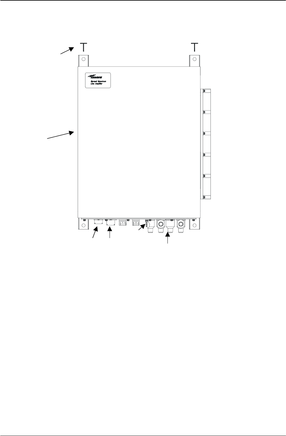
1.4 LOCATIONS AND DESCRIPTIONS OF MAJOR COMPONENTS
Refer to Figure 1-1 Distribution Line Amplifier (4 port) for a view of the external connections
of the 4 port DLA. The 2 port DLA does not include J5 or J6. The mechanical outline of the
DLA is given in CHAPTER 6. The following paragraphs contain the description of the
Distribution Line Amplifier.
Figure 1-1 Distribution Line Amplifier (4 port)
1.4.1 Distribution Line Amplifier Principles of Operation
The bi-directional Distribution Line Amplifier operates within two sub-regions of the 2400 –
2483.5 MHz ISM band. It filters and amplifies at the BDR center frequency of 2416.64 MHz.
in one direction (FWD) and at the MDR center frequency of 2467.86 MHz in another direction
(RVS).
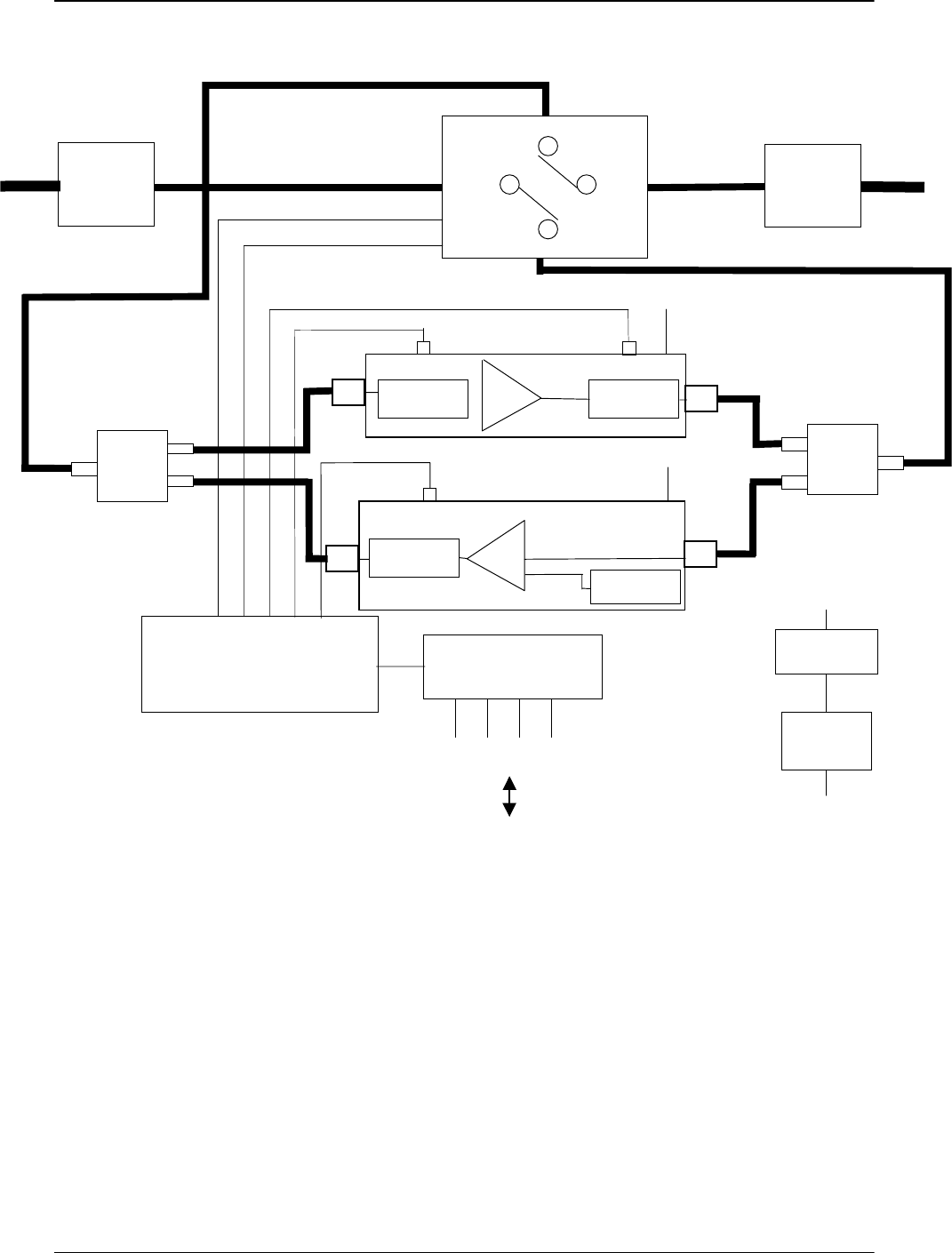
The RF signal at each amplifier is routed through a diplexer (filter) to divide the signal into two
paths: forward and reverse. The DLA has a direction control switch which changes the signal
path to the opposite direction upon the command from the user control equipment network
data interface via the alarm and control interface board. The internal status of the DLA is
monitored by the Amplifier Alarm Detectors. The status signals are sent to the USER control
equipment network data interface via the alarm and control interface.
The BDR path, also referred to as the PA channel or channel 1, contains a power amplifier.
The maximum PA output of the 4 port DLA is < +27 dBm per output port. The PA output port
of the 2 port DLA is < +30 dBm. The PA channel maintains a constant output power over a
user adjustable range. See Table 1-2 Distribution Line Amplifier Specifications for the input
range over which the output power is adjustable. The PA channel also contains an input

385700-4006-006 INTRODUCTION
Document use is restricted to that described on cover 1-7
power level alarm as well as an output power alarm. The alarm levels are user adjustable.
The MDR path is also referred to as the LNA channel or channel 2. The LNA channel is
referenced to a pilot tone within the Distribution Line Amplifier. The pilot tone is used (1) to
set the gain of the LNA channel and (2) to provide a method of detecting a faulty LNA module.
The LNA channel gain is user adjustable. The maximum LNA gain is +27 dB for the 4 port
DLA per output port and +30 dB for the 2 port DLA. See Table 1-2 Distribution Line Amplifier
Specifications for the range over which the gain is adjustable. Under normal operation, the
input signal is expected to be lower (nominally 10 dB) than the pilot tone.
The PA channel input alarm is used to detect a loss of input signal due to cable breakage, etc.
The PA channel output alarm and the LNA channel output alarm are combined to indicate an
amplifier failure.
Refer to Figure 1-2 DLA Block Diagram, for bi-directional amplifier major component
identification.
385700-4006-006 INTRODUCTION
Document use is restricted to that described on cover 1-8
Figure 1-2 DLA Block Diagram
-10 dBm
Radiax
Alarm & Control
Interface Board 24V Lightning
Protectors
RF Lightning
Protection
Transfer
Relay RF Lightning
Protection Radiax
Diplexer
Direction Status
Direction Control
PA
Radiax Alarm
Detector PA Alarm
Detector
+12 VDC
LNA
LNA Alarm
Detector Pilot Tone
Generator
+12 VDC Diplexer
A
larm & Control
Connections
AC-DC
Power Supply
AC
Lightning
Protection
87-265 VAC
+12 VDC
USER Control Equipment
385700-4006-006 INTRODUCTION
Document use is restricted to that described on cover 1-9
1.4.2 Distribution Line Amplifier Major Components
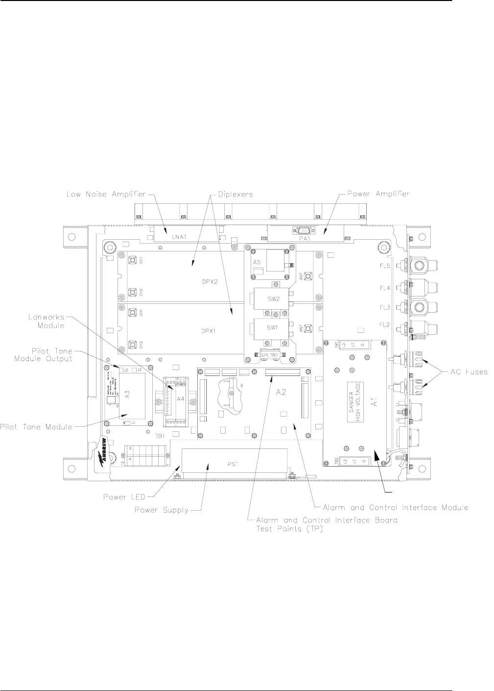
Refer to Figure 1-3 DLA Internal View for locations of major DLA components. The test point
locations, Pilot Tone Output J3 on the Pilot Tone Board and Alarm and Control Interface
Board Test Points J4, shown in
Figure 1-3 are used for initial DLA adjustments and referenced later in this manual in section
2.5.
Figure 1-3 DLA Internal View
Refer to section 2.5.1, Distribution Line Amplifier Setup, for PA and LNA outline views and
controls.
Lightning Protection Module
J1
J8
J5
J2
J9
J7
J6J3 J4
J2
J1

385700-4006-006 INTRODUCTION
Document use is restricted to that described on cover 1-10
1.5 EQUIPMENT CHARACTERISTICS
Refer to Table 1-2 Distribution Line Amplifier Specifications. The table contains the
specifications for the DLA. The table includes characteristics and specifications in three
categories: technical, environmental, and physical.
1.5.1 Power and Utility Requirements
The DLA operates across an AC input range of 87 to 265 VAC. No user adjustment is
required.
1.5.2 Environmental Information
The DLA assembly is designed for above and below ground environments. Refer to Table 1-2
Distribution Line Amplifier Specifications, for more detailed information.
The DLA is housed in a NEMA4X enclosure. It is intended for indoor or outdoor use to
provide a degree of protection against corrosion, windblown dust and rain, splashing water,
and hose-direct water; undamaged by the formation of ice on the enclosure. The NEMA4X
enclosure is manufactured from 16 gauge Type 304 stainless steel.

385700-4006-006 INTRODUCTION
Document use is restricted to that described on cover 1-11
Electrical Specifications
Channels 2
Channel 1, MHz 2416.64 ± 13.5 MHz
Channel 2, MHz 2467.86 ± 13.5 MHz
Input and Output Impedance, ohms 50
Channel 1 (PA channel)
input power -15 dBm to +5 dBm
output power, adjustable +15 to +30 dBm (2 port amplifier)
+12 to +27 dBm (4 port amplifier)
input signal alarm, adjustable -10 dBm nominal
output signal alarm, adjustable +20 dBm nominal
Channel 2 (LNA channel)
input power -25 dBm maximum
output power +0 dBm maximum (2 port amplifier)
-3 dBm maximum (4 port amplifier)
output gain, adjustable 15 to 30 dB
output signal alarm 10 dB below the pilot tone level
Gain, dB ≥ 30 (at maximum gain)
Noise Figure, dB
Channel 1 ≤ 8
Channel 2 ≤ 6
Environment Specifications
Operating Temperature, °C -40 to +70
Storage Temperature, °C -55 to +85
Physical Specifications
Power Requirements 87-265 VAC
47-63 Hz
Power Consumption, watts 50
Dimensions, in (mm) 20 (508) x 16 (406) x 7 (178)
excluding mounting feet
Weight, lbs. (kg) 43 (19.5)
Table 1-2 Distribution Line Amplifier Specifications

385700-4006-006 INSTALLATION
Document use is restricted to that described on cover 2-1
CHAPTER 2
INSTALLATION
2.1 INSTALLING THE DISTRIBUTION LINE AMPLIFIER EQUIPMENT
This chapter provides information to install the Distribution Line Amplifier (DLA) and to prepare
the equipment for use.
2.1.1 Unpacking and Inspection
Unpacking the Distribution Line Amplifier does not require special procedures. Use normal
shop procedures to unpack the equipment.
Carefully inspect the shipping containers and equipment. If the containers show damage,
inspect the equipment in those containers with extra care. Do not open containers with
extreme damage.
Check equipment for bent frames, protrusions, and dents. Pay close attention to external
brackets, controls and connectors, because they are especially susceptible to damage during
shipment.
If you find damage to the equipment, notify Andrew Corporation’s Customer Service Center at:
• 1-800-255-1479 (Inside the USA)
• 708-873-2307 (Outside the USA)
2.1.2 Proper Installation of Units
The amplifier has a weatherproof NEMA4X enclosure. The layout is optimized for vertical
mounting of the amplifier with the cables connected at the bottom of the amplifier. The
enclosure is accompanied with hanger brackets that are used to mount the amplifier. The
type of fasteners will depend on the construction of the mounting surface. Typical
construction in a concrete tunnel would be to use concrete anchors embedded in concrete.
Once DLA is mounted, the power connections and RF connections can be made next.
2.2 INTERCONNECTIONS
Refer to Figure 2-1 DLA Forward Direction Interconnect Diagram, for a block diagram of
wiring runs and connector designations. The following paragraphs describe the
interconnections directly related to the Distribution Line Amplifier.
Before applying power, verify that the
input/output cables are securely
connected to the DLA Input/Output J3 and
J4 ports. Failure to observe these
warnings will damage the equipment.
2.2.1 Forward Direction Configuration Interconnection
WARNING

385700-4006-006 INSTALLATION
Document use is restricted to that described on cover 2-2
In normal usage, the RF connections to the Distribution Line Amplifier are made with non-
radiating coaxial cable that is attached to the main radiating coaxial cable RADIAX®. The non-
radiating RF cable is type HELIAX® LDF4-50A (or equivalent) with N male type connectors.
In the forward configuration, connect the HELIAX® coaxial cable coming from the direction of
BDR or the preceding DLA in a cascaded configuration to the Distribution Line Amplifier at
NORM PA IN/LNA OUT (J4) port on the connector panel of the unit. Connect the HELIAX
coaxial cable coming from the direction of the succeeding DLA in a cascaded configuration at
the DLA NORM PA OUT1/LNA IN (J3) port. See Figure 2-1 DLA Forward Direction
Interconnect Diagram for a typical 4 port configuration. For 2 port configurations, J5 and J6
are not connected. Refer to Andrew Catalog, -- HELIAX® Coaxial Cable – for cable and
connector information.
Connect a nominal 120 VAC power source to the DLA connector panel POWER IN (J1) port.
Refer to Figure 2-3 DLA Input VAC Pin-outs.
The ALARM/CONTROL (J2) connector is connected via cable to the USER control equipment
network data interface. The data interface may be represented by either LONWORKS® type
connection or by twisted pair cable connection. For the dry contacts refer to Figure 2-4 DLA
ALARM/CONTROL Port Pin-outs. The ALARM/CONTROL interface includes a signal that
controls the direction of the line amplifier. In normal usage the direction control is set to
FORWARD.
2.2.2 Reverse Direction Configuration Interconnection
In normal usage, the direction of the amplifier is reversed by controlling the amplifier from the
ALARM/CONTROL interface. The signals are connected to the line amplifier as described in
the previous section. Selecting the reverse direction reverses the direction of the signals
within the line amplifier as well as the signals that appear on J3 and J4 of the line amplifier.
2.3 CABLE AND GROUND REQUIREMENTS
The following paragraphs contain the requirements for constructing the interconnect cabling
between the DLA vendor supplied equipment.
The chassis of the DLA must be bonded to earth with 6-guage solid conductor. See Figure
1-1. Connection to the DLA is made at ground lug provided at the connector panel of the
DLA.
The RF coaxial cables that are connected to the main radiating cable under normal conditions
must support potential bends in the path from the main radiating cable to the DLA plate. Loss
through this cable must be less than 2 dB.
For the ALARM/CONTROL interface (direction and amplifier status signals), construct signal
cabling using 16 gauge shielded cabling.
All signal cables shall be shielded for EMI reduction.
385700-4006-006 INSTALLATION
Document use is restricted to that described on cover 2-3
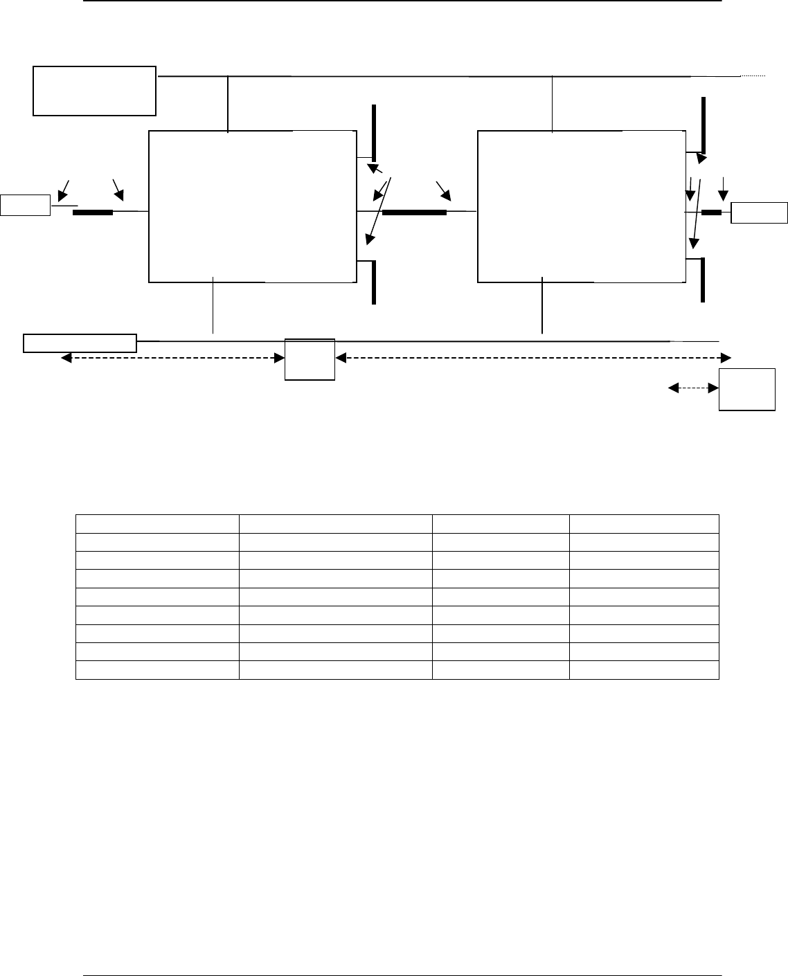
Figure 2-1 DLA Forward Direction Interconnect Diagram
RF Port Frequency Input/Output 4 Port/2 Port
J3 – LNA In 2467.84 MHz ± 13.5 MHz I Y
J3 – Norm PA Out1 2416.64 MHz ± 13.5 MHz O Y
J4 – Norm PA In 2416.64 MHz ± 13.5 MHz I Y
J4 – LNA Out 2467.84 MHz ± 13.5 MHz O Y
J5 – Norm PA Out2 2416.64 MHz ± 13.5 MHz 0 4 Port only
J6 – Norm Det In 2416.64 MHz ± 13.5 MHz I 4 Port only
Table 2-1 – Forward Direction RF Port Functions
FORWARD CONFIGURATION : DIRECTION CONTROL = NORMAL
BDR 1 RADIAX
®
RADIAX
®
HELIAX
®
USER Control
Equipment
DLA DL
A
VAC Power
BDR 2
BDR 1
ZONE BDR 2
ZONE
HELIAX
®
HELIAX
®
RADIAX
®
RADIAX
®
NORM PA OUT1
LNA IN
J3
NORM PA IN
LNA OUT
J4
POWER IN
J1
ALARM/CONTROL
J2 NORM PA
OUT2
J5
NORM DET IN
J6
RADIAX
®
RADIAX
®
NORM PA OUT1
LNA IN
J3
NORM PA IN
LNA OUT
J4
POWER IN
J1
ALARM/CONTROL
J2 NORM PA
OUT2
J5
NORM DET IN
J6
385700-4006-006 INSTALLATION
Document use is restricted to that described on cover 2-4
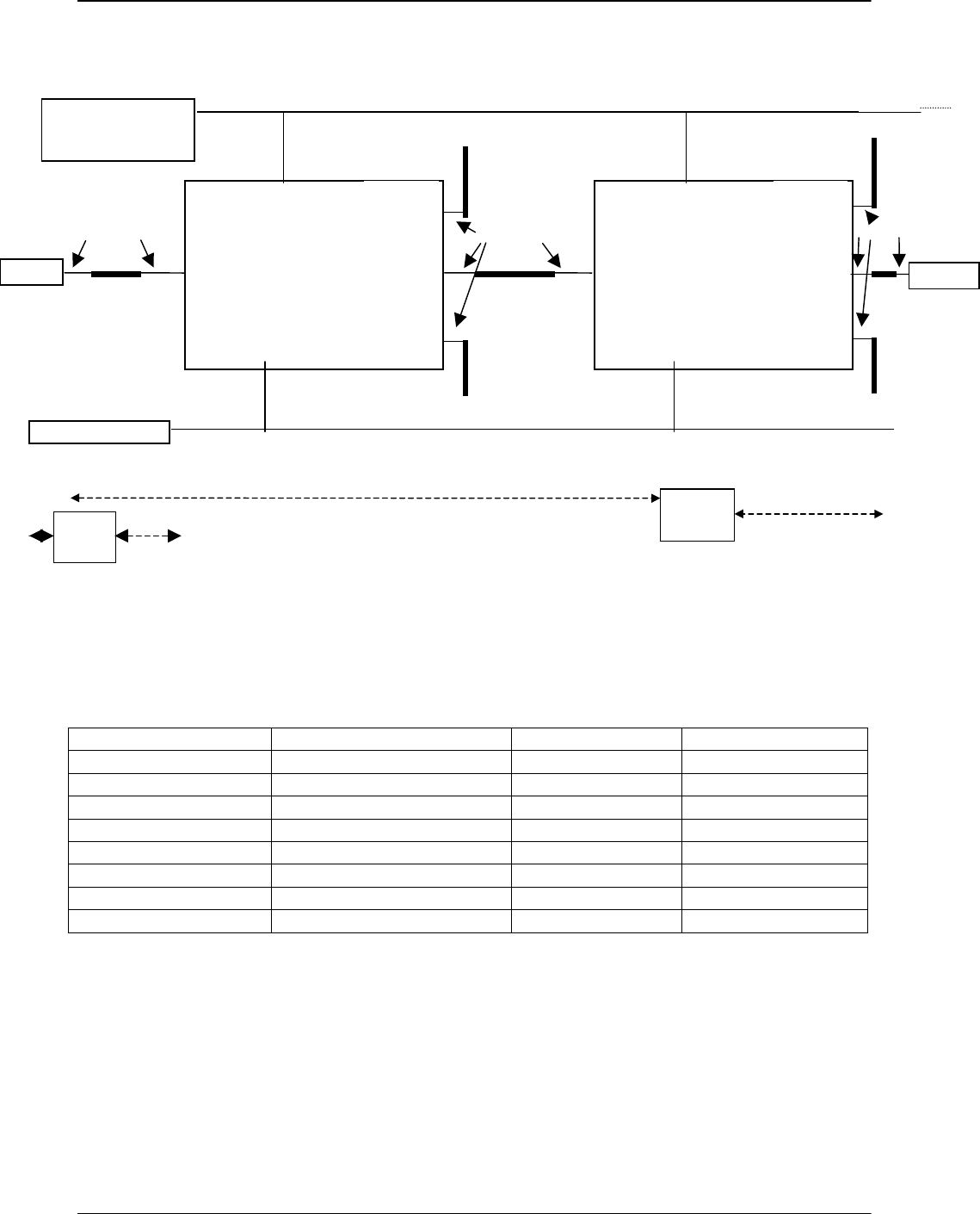
Figure 2-2 DLA Forward Direction Interconnect Diagram
RF Port Frequency Input/Output 4 Port/2 Port
J3 – LNA In 2467.84 MHz ± 13.5 MHz O Y
J3 – Norm PA Out1 2416.64 MHz ± 13.5 MHz I Y
J4 – Norm PA In 2416.64 MHz ± 13.5 MHz O Y
J4 – LNA Out 2467.84 MHz ± 13.5 MHz I Y
J5 – Norm PA Out2 2416.64 MHz ± 13.5 MHz I 4 Port only
J6 – Norm Det In 2416.64 MHz ± 13.5 MHz O 4 Port only
Table 2-2 Reverse Direction RF Port Functions
BDR 1
ZONE
BDR 2
ZONE
BDR 1 RADIAX
®
RADIAX
®
HELIAX
®
USER Control
Equipment
DLA DL
A
VAC Power
BDR 2
HELIAX
®
HELIAX
®
RADIAX
®
RADIAX
®
NORM PA OUT1
LNA IN
J3
NORM PA IN
LNA OUT
J4
POWER IN
J1
ALARM/CONTROL
J2 NORM PA
OUT2
J5
NORM DET IN
J6
RADIAX
®
RADIAX
®
NORM PA OUT1
LNA IN
J3
NORM PA IN
LNA OUT
J4
POWER IN
J1
ALARM/CONTROL
J2 NORM PA
OUT2
J5
NORM DET IN
J6

385700-4006-006 INSTALLATION
Document use is restricted to that described on cover 2-5
2.3.1 Connector Pin-outs
Refer to Figures Figure 2-3 and Figure 2-4 for the connector pin-out information for the
Distribution Line Amplifier ports.
Figure 2-3 DLA Input VAC Pin-outs shows the pin assignments for the Distribution Line
Amplifier POWER IN connector.
Figure 2-3 DLA Input VAC Pin-outs
The DLA Power Connector is a MIL-C-26482, Series 2 connector. The connector is
MS3474W14-4P or equivalent. Mating connectors are MS3475W14-4S, PV75W14-4S,
or equivalent.
385700-4006-006 INSTALLATION
Document use is restricted to that described on cover 2-6
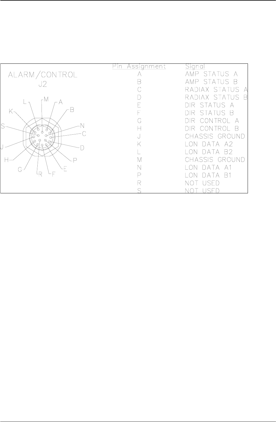
Figure 2-4 DLA ALARM/CONTROL Port Pin-outs, shows the pin assignments for the
Distribution Line Amplifier ALARM/CONTROL connector.
Figure 2-4 DLA ALARM/CONTROL Port Pin-outs
The Alarm/Control connector is a MIL-C-26482, Series 1 connector. The part is MS3124E20-
16P, KPSE07E20-16P, or equivalent. The mating connectors are MS3126F20-16S,
KPSE06F20-16S, or equivalent. These are crimp connectors with a grommet seal and strain
relief. Other options are available including a right angle plug assembly(KPSE08F20-16S)
and solder connections.
385700-4006-006 INSTALLATION
Document use is restricted to that described on cover 2-7
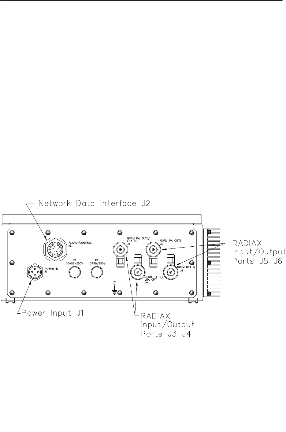
2.4 DISTRIBUTION LINE AMPLIFIER COMPONENT JACK LOCATIONS
The following paragraphs describe the purpose and location of the jacks for the Distribution
Line Amplifier. Refer to Figure 2-5 DLA Assembly Jack Locations. The amplifier connector
panel contains one data jack, ALARM/CONTROL (J2). The DLA exchanges status and
control signals with USER control equipment over ALARM/CONTROL (J2) port.
The NORM PA OUT1/LNA IN (J3) port and NORM PA IN/LNA OUT (J4) are connected to
RADIAX® cable via HELIAX® coaxial cable. The signal (downlink) coming from the BDR is
routed through the section of RADIAX cable to the NORM PA IN/LNA OUT (J4) port of the
DLA. The signal (uplink) coming from the succeeding DLA NORM PA OUT1/LNA IN RF FWD
OUT/RVS IN (J3) port is routed through the section of RADIAX cable to the next DLA in
cascade.
Port POWER IN (J1) connects the DLA to the AC power source.
In the normal direction, NORM PA OUT2 ((J5), if installed, is used with a non cascaded
section of RADIAX® cable.
In the normal direction, NORM DET IN (J6), if installed, is used to terminate a section of
RADIAX® cable.
Figure 2-5 DLA Assembly Jack Locations

385700-4006-006 INSTALLATION
Document use is restricted to that described on cover 2-8
2.5 PREPARATION FOR USE
Before applying power to the Distribution
Line Amplifier, securely connect the RF
ports to 50-ohm terminations. Failure to
observe these cautions can damage the
equipment.
2.5.1 Distribution Line Amplifier Setup
A Distribution Line Amplifier is part of a wayside antenna system; a RADIAX based signal
distribution system. The amplifier provides signal gain to offset the signal loss of the system.
The signal loss is based on the length and type of cable used. The Distribution Line Amplifier
includes gain adjustments for both channels as well as adjustable thresholds for the status
signals.
Channel 1, whose center frequency is 2416.64 MHz, is referred to as the Power Amplifier (PA)
or downlink channel. Refer Figure 1-3 DLA Internal View for the location of the PA module
(part number 385700-2012). The output of this channel is a nominal +30 dBm for a two port
DLA. The output of a 4 port DLA is a nominal +27 dBm per PA output port. For the downlink
channel, the signal input level as well as the output level are monitored. R1, R2, and R3 are
adjustment points on the PA module. See Figure 2-7 PA Module Outline for more details.
Channel 2, whose center frequency is 2467.84 MHz, is referred to as the Low Noise Amplifier
(LNA) or uplink channel. Refer to Figure 1-3 DLA Internal View, for for the location of the LNA
module (part number 385700-2011). A pilot tone module within the Distribution Line Amplifier
serves as a constant input signal for the LNA channel. The output level of the pilot tone is
monitored within the LNA module. No user adjustment of this signal is required. Because of
the diplexers within the DLA the pilot tone may not be observable at the external DLA coaxial
connectors. The input signal range of the LNA channel is approximately -30 dBm to < -100
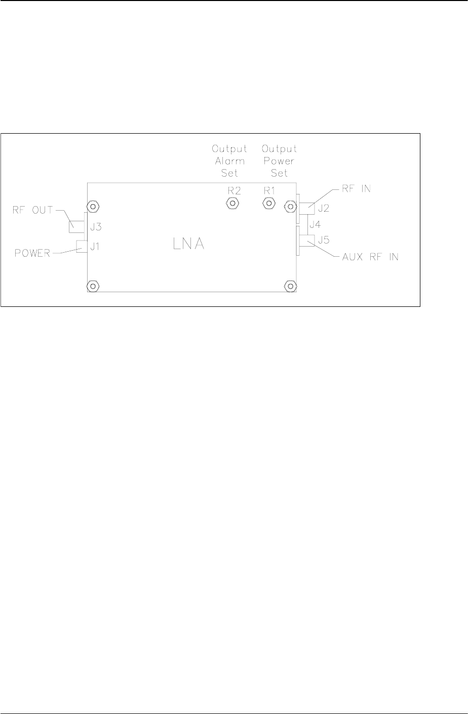
dBm. R1 and R2 are adjustment points on the LNA module. See Figure 2-8 LNA Module
Outline for more details.
A configuration sheet is included with the DLA that specifies the adjustable settings at the time
of shipping the equipment.
The direction of the DLA must be set by the user for proper operation. The amplifier direction
status is indeterminate after powering up the unit. This manual assumes that either the user’s
system control interface is available or a test box similar to an example given at the end of this
manual is used.
CAUTION
385700-4006-006 INSTALLATION
Document use is restricted to that described on cover 2-9
2.5.2 Distribution Line Amplifier Initial Operational Adjustments
2.5.2.1 Input AC Power
The Distribution Line Amplifier AC power supply automatically senses the input AC voltage.
The DLA input voltage range is 87-265 VAC. Refer to Table 1-2 Distribution Line Amplifier
Specifications.
2.5.2.2 Power Amplifier (PA) Channel (Channel 1)
The nominal output level of the PA channel, as set at the time of manufacturing, is set to +27
dBm (4 port) or +30 dBm (2 port). The output alarm level is set for a threshold of 10 dB below
the expected output level. The expected input is 0 dBm. The input signal level threshold is
set for 10 dB below the input level. If other levels are desired, the customer should contact
Andrew with additional information when ordering the equipment. Refer to Figure 2-7 PA
Module Outline, for PA adjustment points locations.
2.5.2.2.1 PA Equipment Setup
The equipment required to adjust the PA output level is:
• Signal Generator
• Power Meter or Spectrum Analyzer
• Digital Volt Meter
• small Blade Screwdriver
• ≥ 10 dB power attenuator
• direction control signal
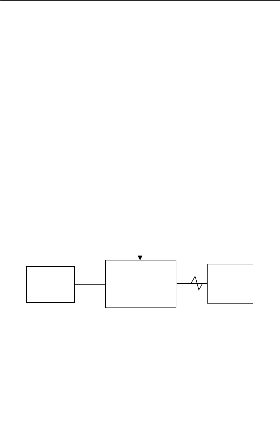
Refer to Table 4-2 Test Equipment for a listing of suggested equipment. Refer to Figure 2-6
PA Output Level Test Setup, for test equipment setup.
Figure 2-6 PA Output Level Test Setup
The signal generator should be set for an output frequency of 2416.64 MHz with an output
level of 0 dBm.
The power meter, if used, should be configured to measure signals from 0 dBm to +40 dBm.
This can be done by either using the appropriate power sensor head(s) or by using power
attenuators.
≥ 10 dB
power
attenuator
Signal
Generator
Distribution Line
Amplifier Assembly
J4 J3
Power Meter
or
Spectrum
Analyzer
J2
Direction Control = Forward
385700-4006-006 INSTALLATION
Document use is restricted to that described on cover 2-10
The spectrum analyzer, if used, should be configured as follows:
Center Frequency 2416.64 MHz
Span 2 MHz
RBW 30 KHz
VBW 3 Hz
Ref. Level as required
Attach a ≥ 10 dB, 2 watt or greater, power attenuator to the spectrum analyzer RF input.
The direction control signal characteristics required will depend on the interface option
installed. The direction must be set to the NORMAL state.
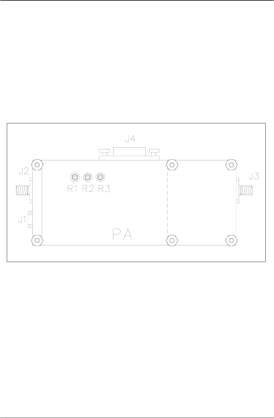
Figure 2-7 PA Module Outline
2.5.2.2.2 PA Input Alarm Adjustment
Set the signal generator output to RF ON. Adjust the output level of the generator to 10 dB
less than the expected input level. If this level exceeds the range of the input detector, the
detector should be set to its minimum detectable level.
R1 = Input Threshold Set
R2 = Output Level Set
R3 = Output Threshold Set

385700-4006-006 INSTALLATION
Document use is restricted to that described on cover 2-11
Attach a voltmeter to J4-3 on the Alarm I/O board. (PA input alarm test point). TP1 or TP2
can be used as the ground connection. Refer to Figure 1-3 DLA Internal View for the location
of the Alarm and Control Interface Board test points. Standard 0.080 test probes should be
used for test points.
Adjust R1 (Input Alarm Set) on the PA module for TP3 to go to the high condition (≥ 3 VDC),
low (≤1 VDC), and then high again. Reduce the signal generator level by 2 dB and verify that
the alarm is asserted. Increase the signal generator level by 4 dB and verify that the alarm is
negated. If needed, readjust R1 and repeat this process as necessary.
2.5.2.2.3 PA Output Adjustment
Set the signal generator output to RF ON at the nominal input level (i.e. 0 dBm). The
maximum input level is +5 dBm. Adjust R2 (Output Power Set) on the PA module to obtain
the desired amplifier output level. Note that the actual level measured will depend on the
attenuation used on the spectrum analyzer or power meter.
2.5.2.2.4 PA Output Alarm Adjustment
Attach a voltmeter to J4-1 on the Alarm I/O relay board. (P.A. output Alarm test point). TP1 or
TP2 can be used as the ground connection.
Adjust the signal generator level as necessary to obtain 10 dB below the desired output power
as observed at J3 (FWD OUT/RVS IN) port. If this level exceeds the range of the output
detector, the detector should be set to its minimum detectable level.
Adjust R3 (output Alarm Set) on PA for high condition (> 3 VDC), low (< 1.0 VDC), and then
high again. Reduce the signal generator level until the alarm is asserted. Verify that the output
level is ± 2 dB of the desired level. If needed, readjust R3 and repeat this process as
necessary.
385700-4006-006 INSTALLATION
Document use is restricted to that described on cover 2-12
2.5.2.3 Low Noise Amplifier (LNA) Channel (Channel 2)
The nominal gain of the LNA channel, as set at the time of manufacturing, is set to 30 dB.
The output alarm level is set for a threshold nominally 10 dB below the expected output pilot
level. The expected signal input range is -40 to -90 dBm. If other settings are desired, the
customer should contact Andrew with additional information when ordering the equipment.
Refer to Figure 2-8 LNA Module Outline, for LNA adjustment points locations.
Figure 2-8 LNA Module Outline
2.5.2.3.1 LNA Adjustment Equipment Setup
The equipment required to adjust the LNA output level is:
• signal generator
• power meter or spectrum analyzer
• digital volt meter
• small Blade screwdriver
• ≥ 10 dB power attenuator
• 50 ohm SMA termination
• direction control interface
See Table 4-2 Test Equipment, for a listing of suggested equipment. Refer to Figure 2-9
LNA Output Level Test Set Up, for test equipment setup.
The signal generator should be set for an output frequency of 2467.86 MHz with an output
level of -40 dBm.
The power meter, if used, should be configured to measure signals from -70 dBm to 0 dBm.
This can be done by either using the appropriate power sensor head(s) or by using
attenuators.
The spectrum analyzer, if used, should be configured as follows:

385700-4006-006 INSTALLATION
Document use is restricted to that described on cover 2-13
Center Frequency 2467 MHz
Span 2 MHz
RBW 30 KHz
VBW 3 Hz
Ref. Level as required
Attach a 10 dB, 2 watt or greater, power attenuator to the spectrum analyzer RF input.
The direction control signal characteristics required will depend on the interface option
installed. The direction must be set to the NORMAL state.
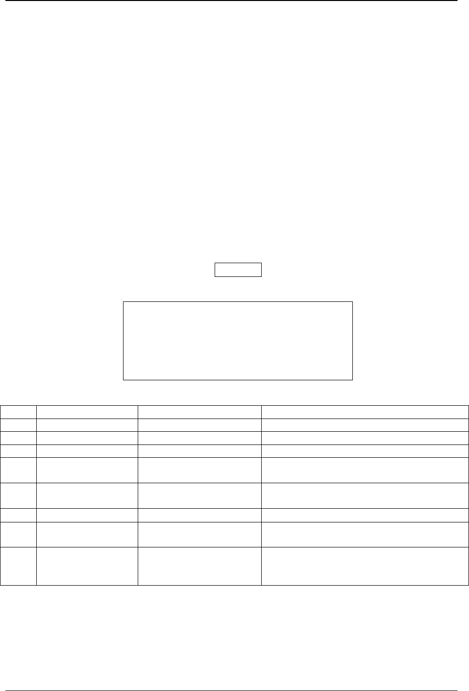
Figure 2-9 LNA Output Level Test Set Up
2.5.2.3.2 LNA Output Adjustment
Disconnect the pilot tone signal from the LNA module J5 Aux RF IN port. Terminate the pilot
tone input port with a 50 ohm termination.
Connect the signal generator to J3 of the DLA as shown in Figure 2-9 LNA Output Level Test
Set Up.
Adjust R1 so that the signal at J3 at 2467 MHz is the desired level ±0.5 dB. The maximum
output value for the LNA channel is +5 dBm.
With the LNA output set, go to the next step to set the LNA output alarm adjustment.
Signal
Generator
Distribution Line
Amplifier Assembly
J3 J4
Power Meter
or
Spectrum
Analyzer
≥ 10 dB
power
attenuator
Direction Control = Forward

385700-4006-006 INSTALLATION
Document use is restricted to that described on cover 2-14
2.5.2.3.3 LNA Output Alarm Adjustment
The previous step must be completed
before adjusting the output alarm.
Attach a voltmeter to J4-2 (LNA output Alarm test point) on the Alarm I/O board. TP1 or TP2
can be used as the ground connection.
Adjust R2 on the LNA until the voltage on J4-2 goes high (≥ 3 VDC), low (≤ 1.0 VDC), and
then high again.
Decrease the signal generator output as required to obtain a 10 dB drop in output level, from
the level set in the previous section, of the LNA channel.
Adjust R2 on the LNA until the voltage on TP2 goes low (≤ 1.0 VDC), high (≥ 3 VDC), and
then low (≤ 1.0 VDC) again. Increase the signal generator input by 10 dB and verify that the
output alarm signal at TP2 is high (≥ 3 VDC). Decrease the signal generator level by 10 dB
and verify that the output alarm signal at TP2 is low (≤ 1.0 VDC). Readjust R2 and repeat as
necessary.
Remove the SMA termination from the LNA module J5 Aux RF IN port and reattach the pilot
tone signal cable to the LNA module J5 Aux RF IN port.
2.5.3 Operational Check-Out
Attach a 2 watt or greater 10 dB power attenuator to the J3 and J4 ports of the DLA. From the
configuration documentation sent with the amplifier or using on site documentation that
reflects any changes from the factory settings, determine the output level settings of the PA
and LNA channels, the PA input alarm level, and the PA and LNA output alarm levels.
2.5.3.1 Forward PA Channel Verification
Set the DLA direction to the forward direction.
2.5.3.1.1 PA Output Level Verification
Attach either a signal generator (frequency = 2417 MHz) or a BDR to J4 (FWD IN/RVS OUT)
port of the Distribution Line Amplifier Assembly. Adjust the signal generator or BDR signal
level at J4 to 0 dBm ± 0.1 dB. Using a power meter verify that the signal level at the J3 (FWD
OUT/RVS IN) port of the Distribution Line Amplifier Assembly equals Gpa dBm ± 1 dB where
Gpa is equal to the expected gain of the PA channel. If the gain is not equal to Gpa dBm ± 1
dB, perform the steps outlined in section 2.5 for the PA output adjustment. If after completing
the amplifier setup procedure the output level of the PA channel is not Gpa dBm ± 1 dB and all
N
O
TE

385700-4006-006 INSTALLATION
Document use is restricted to that described on cover 2-15
external test measurement cable losses are accounted for, the amplifier should be replaced.
Contact Andrew for additional information.
2.5.3.1.2 PA Input Signal Alarm
Attach a voltmeter to J4-3 on the Alarm I/O relay board (PA output alarm test point). TP1 or
TP2 can be used as the ground connection. After removing the signal from the J4 (FWD
IN/RVS OUT) port of the Distribution Line Amplifier Assembly verify that J4-3 is < 0.7 VDC. If
J4-3 is > 1.0 VDC, perform the steps outlined in section 2.5 for the PA input alarm adjustment.
If after completing the amplifier setup procedure the input alarm is not < 0.7 VDC with no input
to J4, the amplifier should be replaced. Contact Andrew for additional information.
2.5.3.1.3 PA Output Signal Alarm
Attach a voltmeter to J4-1 on the Alarm I/O relay board (PA output alarm test point). TP1 or
TP2 can be used as the ground connection. After removing the signal from the J4 (FWD
IN/RVS OUT) port of the Distribution Line Amplifier Assembly verify that J4-1 is < 0.7 VDC. If
J4-1 is > 1.0 VDC perform the steps outlined in section 2.5 for the PA output alarm
adjustment. If after completing the amplifier setup procedure the input alarm is not < 0.7 VDC
with the expected input to J4, the amplifier should be replaced. Contact Andrew for additional
information.

385700-4006-006 INSTALLATION
Document use is restricted to that described on cover 2-16
2.5.3.2 Forward LNA Channel Verification
Set the DLA direction to the forward direction.
2.5.3.2.1 LNA Output Level Verification
Attach either a signal generator (frequency = 2467 MHz) or a MDR to J3 (FWD OUT/RVS IN)
port of the Distribution Line Amplifier Assembly. Adjust the signal generator or BDR signal
level at J3 to -50 dBm ± 1 dB. Using a power meter verify that the signal level at the J4 (FWD
IN/RVS OUT) port of the Distribution Line Amplifier Assembly equals Glna dBm ± 1 dB where
Glna is equal to the expected gain of the LNA channel. If the gain is not equal to Glna dBm ± 1
dB perform the steps outlined in section 2.5 for the LNA output adjustment. If after completing
the amplifier setup procedure the output level of the LNA channel is not Glna dBm ± 1 dB and
all external test measurement cable losses are accounted for, the amplifier should be
replaced. Contact Andrew for additional information.
2.5.3.2.2 LNA Output Signal Alarm
This step assumes that the LNA output level has been set as explained in section 2.5.3.2.1
Attach a voltmeter to J4-2 on the Alarm I/O relay board (LNA output alarm test point). TP1 or
TP2 can be used as the ground connection. Remove the pilot tone cable from the LNA
module J5 Aux RF IN port port. Verify that J4-2 on the Alarm I/O relay board is < 0.7 VDC. If
J4-2 is > 0.7 VDC, perform the steps outlined in section 2.5 for the LNA output alarm
adjustment. If after completing the amplifier setup procedure the output alarm is not < 0.7
VDC with the previously set input level to J3, the amplifier should be replaced. Contact
Andrew for additional information.
2.5.3.3 Reverse PA Channel Verification
Set the DLA direction to the reverse direction.
2.5.3.3.1 PA Output Level Verification
Attach either a signal generator (frequency = 2417 MHz) or a BDR to J3 (FWD OUT/RVS IN)
port of the Distribution Line Amplifier Assembly. Adjust the signal generator or BDR signal
level at J3 to 0 dBm ± 1 dB. Using a power meter verify that the signal level at the J4 (FWD
IN/RVS OUT) port of the Distribution Line Amplifier Assembly equals Gpa dBm ± 1 dB where
Gpa is equal to the expected gain of the PA channel. If the gain is not equal to Gpa dBm ± 1
dB and the Distribution Line Amplifier has not been tested for the forward direction, perform
the steps outlined in section 2.5 for the PA output adjustment. If after completing the
amplifier setup procedure the output level of the PA channel is not Gpa dBm ± 1 dB and all
external test measurement cable losses are accounted for, the amplifier should be replaced.
Contact Andrew for additional information.

385700-4006-006 INSTALLATION
Document use is restricted to that described on cover 2-17
2.5.3.3.2 PA Input Signal Alarm
Attach a voltmeter to J4-3 on the Alarm I/O relay board (PA output alarm test point). TP1 or
TP2 can be used as the ground connection. After removing the signal from the J3 (FWD
OUT/RVS IN) port of the Distribution Line Amplifier Assembly verify that J4-3 is < 0.7 VDC. If
J4-3 is > 0.7 VDC and the Distribution Line Amplifier has not been tested for the forward
direction, perform the steps outlined in section 2.5 for the PA input alarm adjustment. If after
completing the amplifier setup procedure the input alarm is not < 0.7 VDC with no input to J4,
the amplifier should be replaced. Contact Andrew for additional information.
2.5.3.3.3 PA Output Signal Alarm
Attach a voltmeter to TP1 on the Alarm I/O relay board (PA output alarm test point). TP1 or
TP2 can be used as the ground connection. After removing the signal from J3 (FWD
OUT/RVS IN) port of the Distribution Line Amplifier Assembly, verify that J4-1 is < 0.7 VDC. If
J4-1 is > 0.7 VDC and the Distribution Line Amplifier has not been tested for the forward
direction, perform the steps outlined in section 2.5 for the PA output alarm adjustment. If after
completing the amplifier setup procedure the input alarm is not < 0.7 VDC with the expected
input to J4, the amplifier should be replaced. Contact Andrew for additional information.
2.5.3.4 Reverse LNA Channel Verification
Set the DLA direction to the reverse direction.
2.5.3.4.1 LNA Output Level Verification
Attach either a signal generator (frequency = 2467 MHz) or a MDR to J4 (FWD IN/RVS OUT)
port of the Distribution Line Amplifier Assembly. Adjust the signal generator or BDR signal
level at J4 to -50 dBm ± 1 dB. Using a power meter verify that the signal level at the J3 (FWD
OUT/RVS IN) port of the Distribution Line Amplifier Assembly equals Glna dBm ± 1 dB where
Glna is equal to the expected gain of the LNA channel. If the gain is not equal to Glna dBm ± 1
dB and the Distribution Line Amplifier has not been tested for the forward direction, perform
the steps outlined in section 2.5 for the LNA output adjustment. If after completing the
amplifier setup procedure the output level of the LNA channel is not Glna dBm ± 1 dB and all
external test measurement cable losses are accounted for, the amplifier should be replaced.
Contact Andrew for additional information.
2.5.3.4.2 LNA Output Signal Alarm
This step assumes that the LNA output level has been set as explained in section 2.5.3.2.1
Attach a voltmeter to J4-2 on the Alarm I/O relay board (PA output alarm test point). TP1 or
TP2 can be used as the ground connection. Remove the pilot tone cable from the LNA
module J5 Aux RF IN port. Verify that J4- on the Alarm I/O relay board is < 0.7 VDC. If J4-2
is > 0.7 VDC, perform the steps outlined in section 2.5 for the LNA output alarm adjustment.
If after completing the amplifier setup procedure the output alarm is not < 0.7 VDC with the
previously set input level to J3, the amplifier should be replaced. Contact Andrew for additional
information.

385700-4006-006 OPERATIONS
Document use is restricted to that described on cover 3-1
CHAPTER 3
OPERATIONS
3.1 WIRING PROTECTION AND GROUNDING
The Distribution Line Amplifier does not have controls and indicators accessible from the
outside of the unit. The DLA has two 10 Ampere fuses F1 and F2 for wiring protection on the
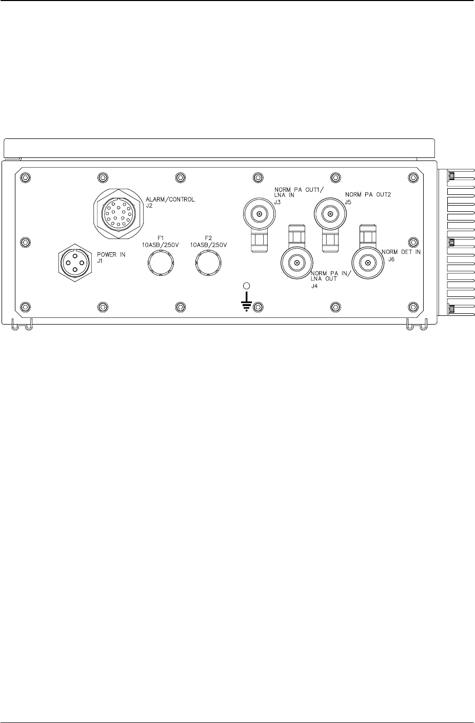
connector panel. Refer to Figure 3-1 DLA Connector Panel Layout.
There is a ground stud on the DLA connector panel for a ground wire connection. Refer to
Figure 3-1 DLA Connector Panel Layout.
Figure 3-1 DLA Connector Panel Layout

385700-4006-006 OPERATIONS
Document use is restricted to that described on cover 3-2
3.2 STARTUP AND SHUTDOWN PRODECURES
The following procedures ensure that installation does not damage the equipment.
3.2.1 DLA Startup
Refer to section 4.2.1, for procedures to properly install the DLA. Mount the DLA in the
equipment room or in the tunnel with no connections made. To start the DLA perform the
following:
1. Securely connect HELIAX® cables to DLA J3 and J4 ports.
2. Connect the USER control equipment to the DLA connector panel J2 port.
3. Connect the VAC power supply to the DLA J1 port.
3.2.2 Normal Operation
Refer to section 1.4.1, Distribution Line Amplifier Principles of Operation.
3.2.3 Shutdown
Disconnect the DLA from the VAC power source.
WARNING
IN CASE OF EMERGENCY; Immediately
turn off power to the unit.
385700-4006-006 MAINTENANCE AND TROUBLESHOOTING
Document use is restricted to that described on cover 4-1
CHAPTER 4
MAINTENANCE AND TROUBLESHOOTING
4.1 TROUBLESHOOTING
Before beginning any in-depth troubleshooting, ensure that power is available to the unit. Ensure
that all cable connections are secure.
Table 4-1 DLA Fault Isolation, describes the troubleshooting procedures for the DLA. Locate
the unit’s symptom in the Fault Indication column. The Fault Description column lists
components or functions that can cause faults. The last column, Corrective Action, specifies the
action necessary to correct the fault. After taking corrective action, perform the appropriate
diagnostic procedure to verify that the correction was successful.
For malfunctions that the fault isolation table does not list, contact Andrew’s technical support
personnel.
NOTE
The following table only isolates faults to
the LRU level. The test procedures in
Section III of this chapter provide
assistance for further fault isolation. If an
LRU fails, return it to the equipment
manufacturer for maintenance or repair.
Step Fault Indication Fault Description Corrective Action
1 No output signal No input power Verify power input cable
2 No output signal No power in amplifier Replace fuses
3 No output signals Poor connections Verify connections
4RADIAX Alarm No BDR input signal Verify cables connections to J4 (forward
direction) or J3 (reverse direction)
5RADIAX Alarm No BDR input signal Verify preceding cascaded amplifier is
operational
6RADIAX Alarm No BDR input signal If valid inputs, replace amplifier
7 Amplifier Alarm No BDR and/or MDR
output RF signals If valid inputs, replace amplifier
8 Direction Control
invalid status Direction control status
is opposite of direction
control input control
If valid inputs, replace amplifier
Table 4-1 DLA Fault Isolation

385700-4006-006 MAINTENANCE AND TROUBLESHOOTING
Document use is restricted to that described on cover 4-2
4.2 CORRECTIVE MAINTENANCE
This section describes the removal and replacement of the DLA. See Table 4-1 DLA Fault
Isolation, to determine when to remove and replace a line replaceable unit (LRU).
4.2.1 Remove and Replace DLA
Referring to Figure 4-1 Remove and Replace DLA, perform the following actions to remove the
DLA (shown as Item 2)
1. Disconnect VAC power cable from DLA (2) POWER IN (3) port.
2. Disconnect the USER control equipment data cable that attaches to the DLA’s
ALARM/CONTROL port (6).
3. Disconnect the HELIAX® cables from the RADIAX® input/out ports (4) and (5).
4. Disconnect grounding wire from the grounding stud (7) on the connector panel of
the DLA.
5. Remove four bolts (1) from the DLA (2) mounting brackets.
6. Remove DLA (2).
Referring to Figure 4-1 Remove and Replace DLA, perform the following actions to replace the
DLA:
1. Place DLA (2) in position.
2. Secure DLA (2) with four bolts (1).
3. Reconnect the HELIAX cables to RADIAX input/output ports (4) and (5).
4. Reconnect the USER control equipment data cable that attaches to the DLA’s
ALARM/CONTROL port (6).
5. Reconnect the grounding wire to grounding stud (7).
6. Reconnect the VAC power cable to the POWER IN (3) port.
7. Configure Channel 1 and Channel 2 output level and status alarm
adjustments per section 2.5.2 if not already performed.
385700-4006-006 MAINTENANCE AND TROUBLESHOOTING
Document use is restricted to that described on cover 4-3
Figure 4-1 Remove and Replace DLA
3
2
4
5
6
7
1
385700-4006-006 MAINTENANCE AND TROUBLESHOOTING
Document use is restricted to that described on cover 4-4
4.3 TEST PROCEDURES
Refer to Table 4-2 Test Equipment, for a list of test equipment to perform the following test
procedures. If necessary, substitute an equivalent to the equipment listed.
The following test procedures help the user verify that a DLA is faulty. Return faulty amplifiers to
Andrew Corporation for maintenance and repair. Refer to paragraph 2.1.1 for equipment return
information.
Equipment Qty Part Number
Spectrum Analyzer 1 HP8561B
Power Meter 1 HP437B
Power Sensor 1 HP8481A
Power Sensor 1 HP8481D
Digital Volt Meter 1 Fluke Model 77
RF Signal Generator 1 HP 8664A
10 dB Power Attenuator As required Inmet 6N10W-10
Variable Attenuator As required HP 8495B
Coaxial Cables As required
Table 4-2 Test Equipment
4.3.1 Inoperative Distribution Line Amplifier
DANGER! High voltage shock hazard.
4.3.1.1 Input Power Verification
Disconnect the power connector to the DLA. Using a DVM verify the levels of the AC input
voltage. See Figure 2-3 DLA Input VAC Pin-outs for additional information. If the input power
level is present, reconnect the power connector to the DLA.
If the input power is available to the DLA, open the amplifier and verify that the LED on the power
supply is illuminated. See Figure 1-3 DLA Internal View. If the LED is illuminated, then verify the
coaxial and Alarm/control signal connections.
If the power supply LED is not illuminated, unscrew the two fuses at the DLA connector plate.
WARNING

385700-4006-006 MAINTENANCE AND TROUBLESHOOTING
Document use is restricted to that described on cover 4-5
Remove the fuses from the holder. Measure the resistance across the fuses. If the resistance is
> 1.0 ohms, replace the fuse. Reinstall the fuses in the DLA. If the fuses are operational and
the power supply remains off, replace the Distribution Line Amplifier.
4.3.1.2 RADIAX
Alarm Asserted
Assertion of the RADIAX input alarm indicates a loss of signal (Signal Center Frequency is
2416.64 MHz) from the preceding Distribution Line Amplifier and or base station radio. The
following trouble shooting procedure assumes that the amplifiers are cascaded in the forward
configuration normal direction mode and that the amplifier has been correctly configured as
indicated in 2.5.
Visually inspect the cable assemblies from the preceding amplifier or radio for loose connections
and or cable breakage. Tighten all cable connections. Replace broken or damaged cables as
necessary.
If all cable assemblies are secure and intact, disconnect the cable at J4 of the DLA. Using a
power meter or spectrum analyzer attached to the cable, verify the presence and expected level
of the RF signal (Fc = 2416.64 MHz, 0 dBm nominal). If the signal is present and the alarm is
configured correctly (refer to section 2.5.2.2.2) the amplifier should be replaced. If the RF signal
is not present continue to determine the origin of the signal loss.
4.3.1.3 Amplifier Alarm Asserted
Assertion of the Amplifier Alarm can be caused by:
• Loss of an input signal on the PA Channel (RADIAX Alarm Asserted)
• Failure of the PA module
• Loss of the Pilot Tone Signal to the LNA module
• Failure of the LNA module.
4.3.1.3.1 Loss of PA Input Signal
When the RADIAX Alarm is asserted, the loss of input signal can also cause the PA module to
also assert its output alarm. With a loss of input signal, the PA module gain is insufficient to
generate a signal level above the level represented by the output threshold detector in the PA
module. If both the RADIAX alarm signal and the Amplifier Alarm signals are asserted, the user
should determine the cause for the loss of input signal.
4.3.1.3.2 PA Module Failure
If the input signal to the PA channel is at the expected level and the PA channel output alarm is
asserted, either the PA module has failed or it is incorrectly configured. The PA module output
alarm can be monitored with a DVM at J4-1 of the Relay/IO board. A voltage level < 1 VDC
indicates a fault condition for the PA channel.
The output signal can be measured with a power meter or spectrum analyzer. If no signal is
detected at the Distribution Line Amplifier output port (J3 for the forward direction) the unit should
be returned to Andrew Corporation. If a signal is present, the user should confirm that the
amplifier output is below the levels indicated on the configuration sheet attached to the
Distribution Line Amplifier. If the input and output signal levels are at the levels specified on the

385700-4006-006 MAINTENANCE AND TROUBLESHOOTING
Document use is restricted to that described on cover 4-6
configuration sheet, the PA module alarm may be indicating a faulty setting on the output level
monitor. Refer to section 2.5.2.2.4 for details on setting the output alarm. If the output level
monitor is correctly configured, the Distribution Line Amplifier should be returned to Andrew
Corporation.
4.3.1.3.3 Loss of Pilot Tone Signal
In a correctly configured DLA, the pilot tone is monitored by the LNA output detector circuit.
Without the pilot tone there may not be sufficient signal at the LNA module output. As a result,
the LNA module will signal an amplifier failure. The pilot tone signal can be monitored with either
a power meter or a spectrum analyzer.
Figure 1-3 DLA Internal View shows the location of the pilot tone module and its output port J3.
The expected output at the pilot tone module J3 port is a nominal - 10 dBm signal at 2401 ± 2
MHz. If this signal is not present, the Distribution Line Amplifier should be returned to Andrew
Corporation. If the signal is present, reattach the cable from J3 of the pilot tone module to the
LNA module AUX RF input port. Tighten the connections as necessary.
4.3.1.3.4 LNA Module Failure
If the pilot tone signal to the LNA channel is at the expected level and the LNA channel output
alarm is asserted, either the LNA module has failed or it is incorrectly configured. The LNA
module output alarm can be monitored with a DVM at J4-2 on the Relay/IO board. A voltage
level < 1 VDC indicates a fault condition for the LNA channel.
In order to measure the output of the LNA channel, it is necessary to inject an external signal into
the LNA channel. The external signal can be either a CW signal at a frequency in the passband
of the LNA channel (see Table 1-2 Distribution Line Amplifier Specifications in section 1.5.2) or it
can be the output signal of an MDR. In either case, the signal input level to J3 of the DLA
(normal forward configuration) should be -50 dBm.
Based on the gain setting specified on the configuration sheet attached to the DLA, the external
signal can be verified with a power meter or spectrum analyzer. If no signal is detected at the
Distribution Line Amplifier output port (J4 for the forward direction) the DLA should be returned to
Andrew Corporation. If a signal is present, the user should confirm that the amplifier output is
below the levels indicated on the configuration sheet attached to the Distribution Line Amplifier.
If the measured level is below the expected value the Distribution Line Amplifier should be
returned to Andrew Corporation. If the input and output signal levels are at the levels specified
on the configuration sheet, the PA module alarm may be indicating a faulty setting on the output
level monitor. Refer to section 2.5 for details on setting the output alarm. If the output level
monitor is correctly configured, the Distribution Line Amplifier should be returned to Andrew
Corporation

385700-4006-006 ORDERING INFORMATION
Document use is restricted to that described on cover 5-1
CHAPTER 5
ORDERING INFORMATION
5.1 PARTS LIST
This chapter provides a list of replacement parts and mating connectors for the Distribution
Line Amplifier assembly. It also provides vendor names and addresses. Table 1-1 – DLA
Part Numbers lists the various versions of the DLA and their respective part numbers. Figure
1-1 Distribution Line Amplifier (4 port) shows all of the items on the list. To procure any of the
parts, contact Andrew Corporation or the appropriate vendor for the part.
The parts list includes three columns: Description, Part Number, and Quantity (Qty). The
Description column identifies the specific part, beginning with the assembly or line-replaceable
unit (LRU) that contains it. The information in the Description column includes an (AP) symbol
to denote attaching hardware for the LRUs. The Part Number column provides the vendor’s
number for that drawing or part. The Quantity column defines how many of the particular part
the next higher assembly (NHA) contains.
Table 5-1 provides a list of applicable vendors and their addresses.
Vendor Address (Phone Number)
Andrew Corporation 2601 Telecom Parkway
Richardson, Texas 75082-3521
(972) 235-7300
ITT Corporation
ITT Canon Division 666 East Dyer Road
Santa Ana, CA 92702
Bussman P.O. Box 14460
St Louis, MO 63178
314-394-2877
Table 5-1 Vendors

385700-4006-006 ORDERING INFORMATION
Document use is restricted to that described on cover 5-2
Table 5-2 provides a list of replaceable parts and mating connectors for the amplifier
assemblies.
Description Part Number Qty
Distribution Line Amplifier 385700-4000 1
Mating Power Connector Assembly (J1) MS3475W14-4S 1
Mating Alarm/Control Connector (J2) MS3126F20-16S or
KPSE08F20-16S 1
AC Fuses (F1, F2) Bussman MDA-10 2
Table 5-2 Parts List
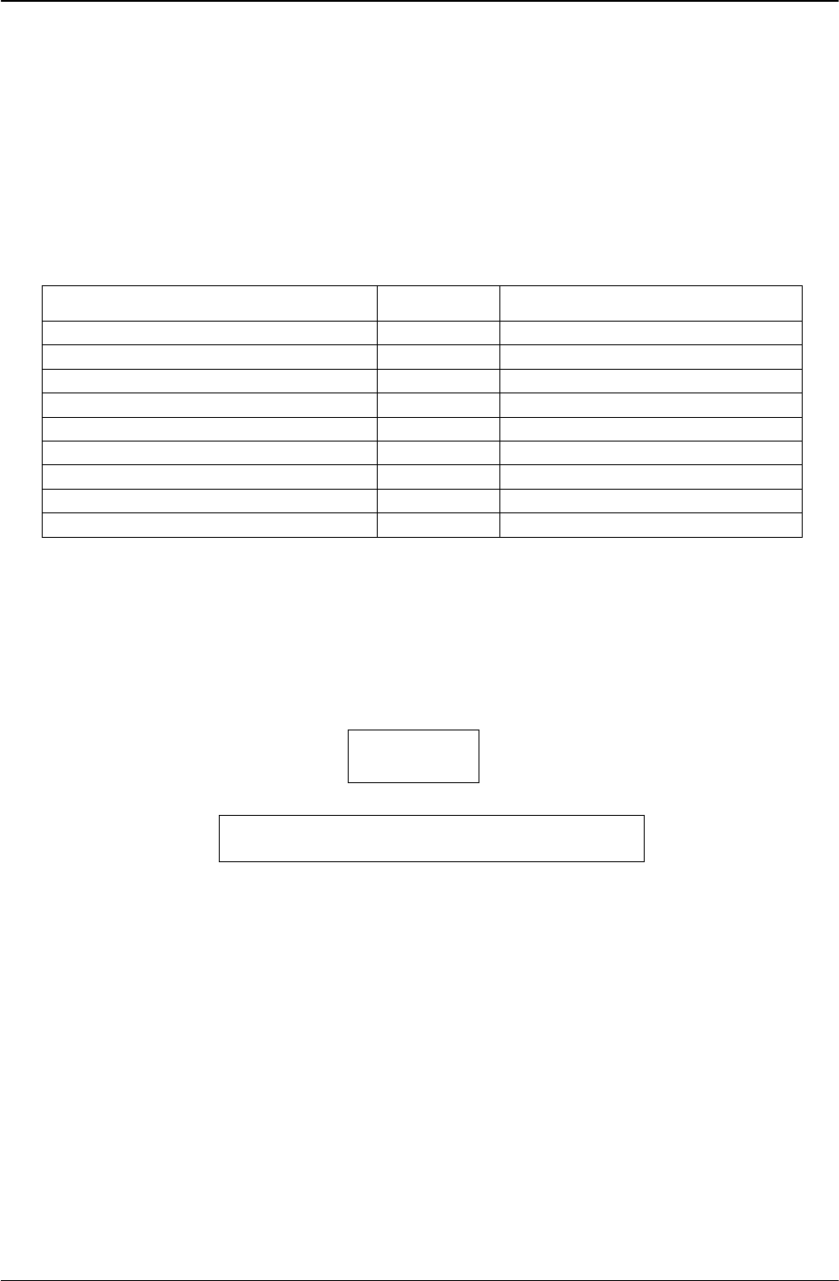
385700-4006-006 MECHANICAL INFORMATION
Document use is restricted to that described on cover 6-1
CHAPTER 6
MECHANICAL INFORMATION
Figure 6-1 DLA Mechanical Outline

385700-4006-006 ALARM/CONTROL TEST
CIRCUIT
Document use is restricted to that described on cover 7-1
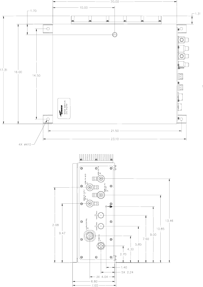
CHAPTER 7
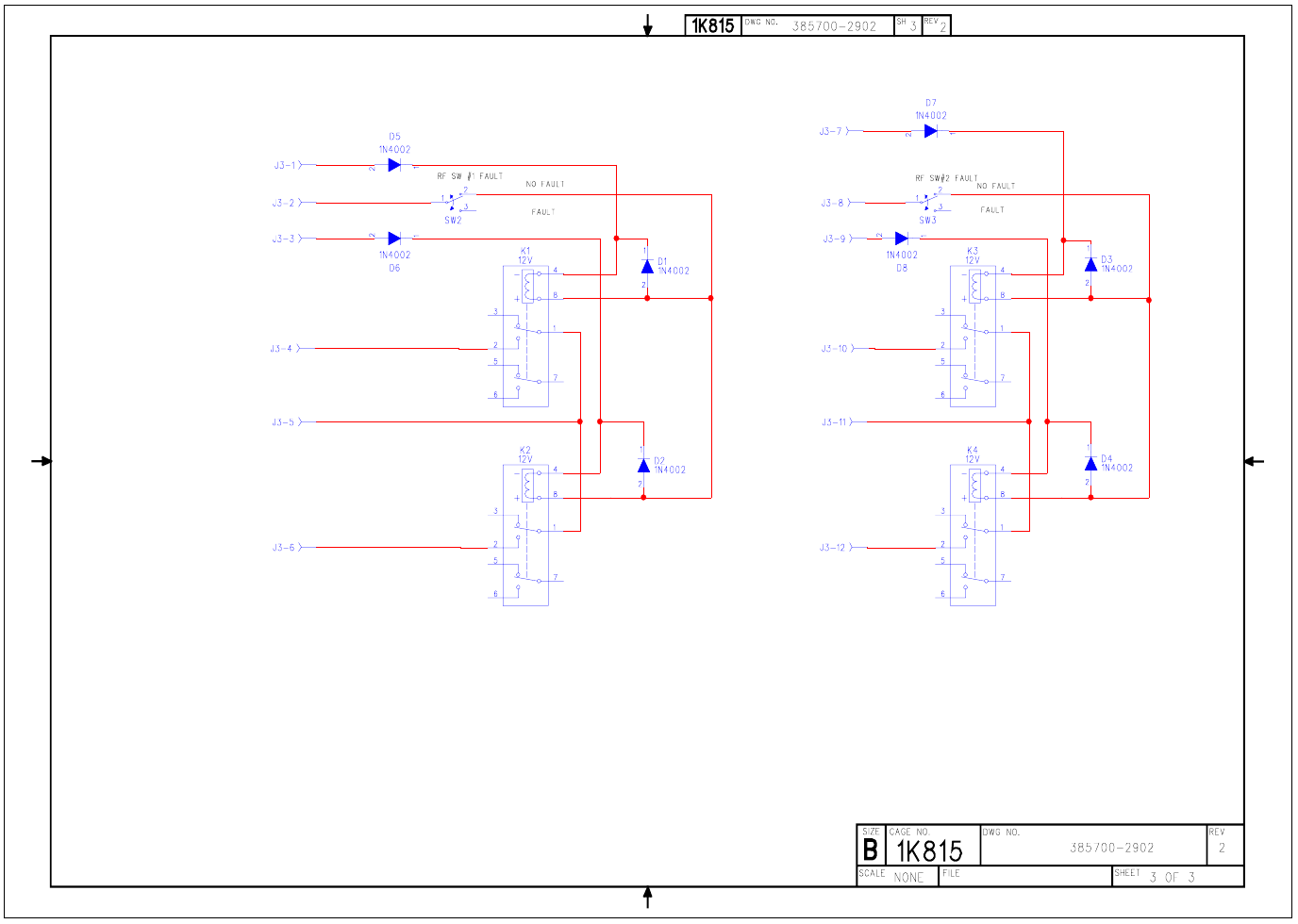
ALARM/CONTROL TEST CIRCUIT
The following schematic can be used to construct a test fixture to control the direction of the DLA and to monitor the status of the various
Figure 7-1
385700-4006-006 ALARM/CONTROL TEST
CIRCUIT
Document use is restricted to that described on cover 7-2
385700-4006-006 ALARM/CONTROL TEST
CIRCUIT
Document use is restricted to that described on cover 7-3
385700-4006-006 ALARM/CONTROL TEST
CIRCUIT
Document use is restricted to that described on cover 7-4
385700-4006-006 ALARM/CONTROL TEST
CIRCUIT
Document use is restricted to that described on cover 7-5
alarms. The test fixture connects to J2 Alarm/Control of the DLA. This test fixture requires an external 24 VDC supply. The circuit should be
mounted within a metal enclosure so that the required cable shielding integrity is maintained.