Andrew MDL2400MDR Mobile Data Radio User Manual OPERATION AND MAINTENANCE MANUAL
Andrew Corporation Mobile Data Radio OPERATION AND MAINTENANCE MANUAL
UserManual.wiki
>
Andrew
>
MDL2400MDR User Manual
>
user manual
Contents
1.
Operation and Maintenance
2.
user manual
user manual
Navigation menu
Upload a User Manual
Namespaces
Wiki Guide
HTML
PDF
Info
Views
User Manual
Discussion / Help
Navigation

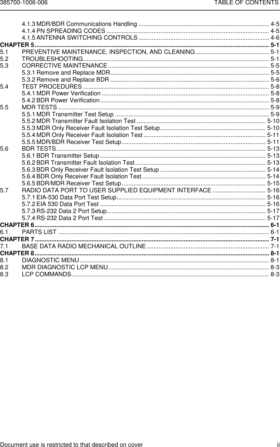

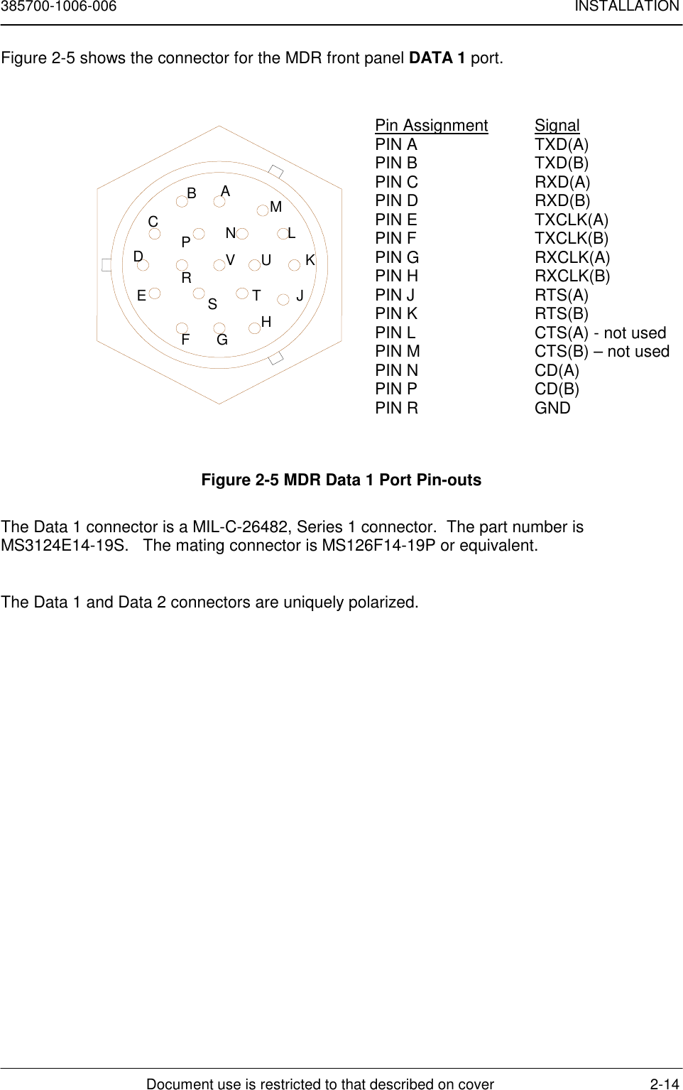
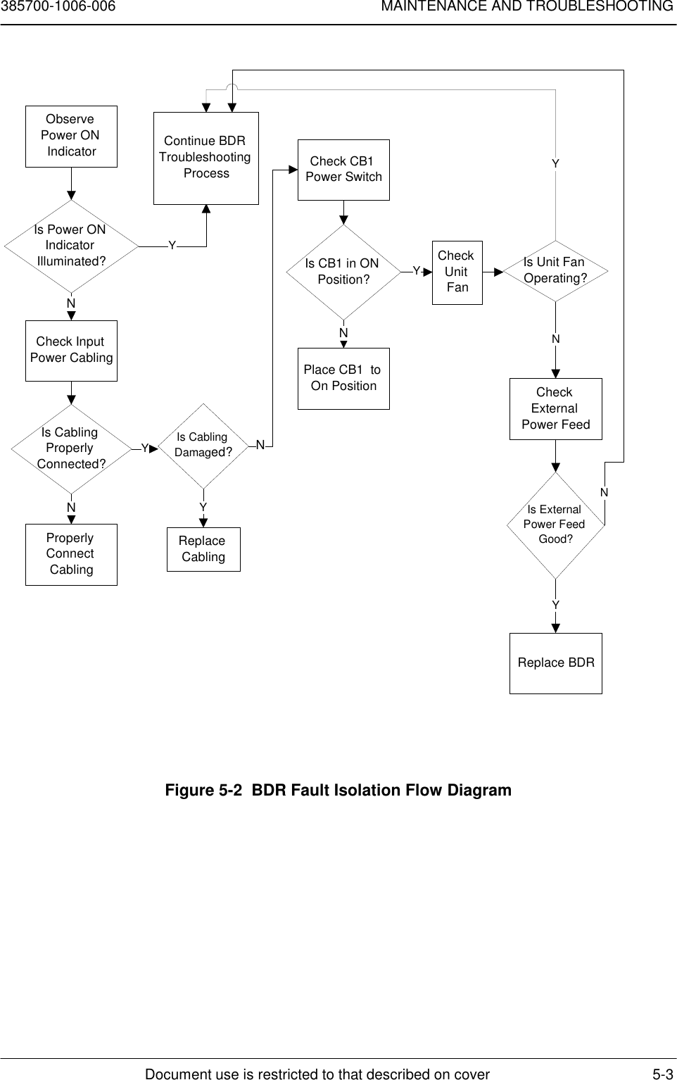
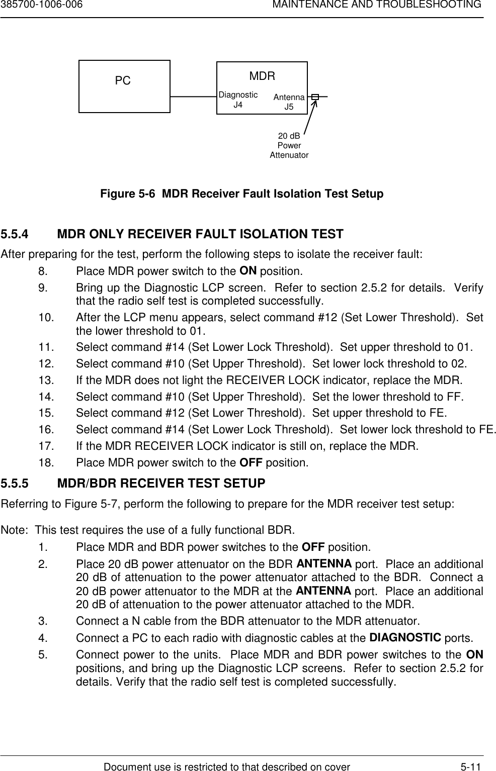
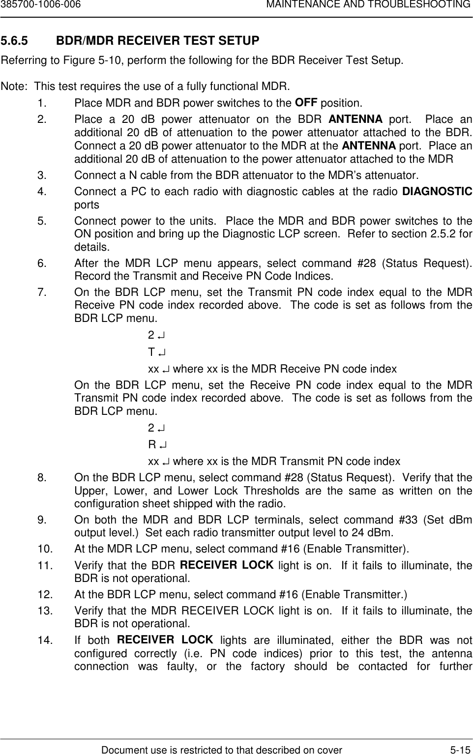
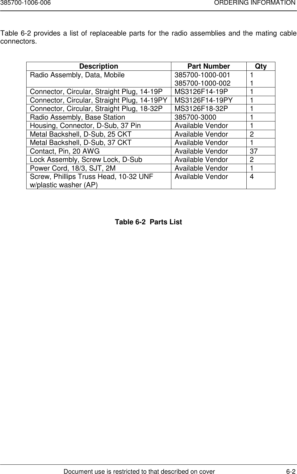
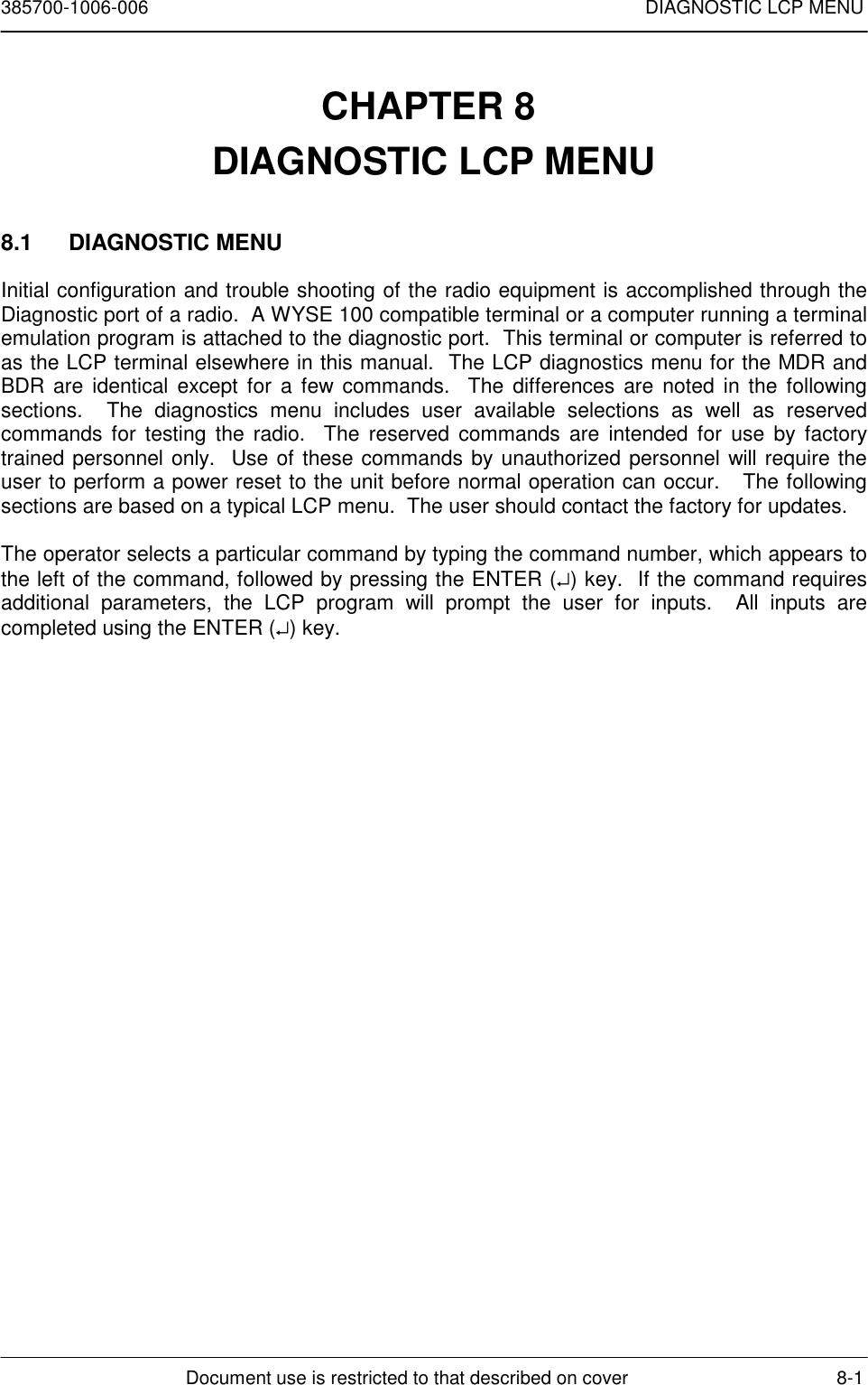
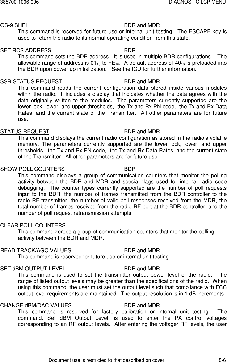
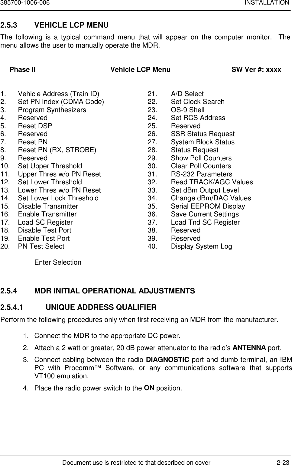
![385700-1006-006 INSTALLATIONDocument use is restricted to that described on cover 2-222.5.2.1 RCS MAINTENANCE AND UPGRADE MENURCS Maintenance and Upgrade Menu[0] Download RCS Software[1] Download Board Level Test Software[2] Download Flash Download Software[3] Download Microwave OS-9 Kernel[4] Download Power-on Self Test[5] Download Boot[6] Run Board Level Test[7] Run RCS[8] Run RCS, without an SCP[9] Display Software Version #’s[10]Reset Radio Enter Option [0 - 10]:NOTE: If a previous version of the application software has been previously loaded, andthe <ENTER> key was not pressed within 3 seconds, the radio will attempt tocommunicate with attached control equipment attached to a DATA port. It willautomatically try to bring up the RCS Application software (option #7). If thisoccurs, the operator will have to recycle power to the radio and hit the <ENTER>key within 3 seconds.If there isn’t any software loaded for the OS-9 program, the following errormessage will be displayed:UNABLE TO RUN RCS: OS-9 Kernel is not present in Flash.If this message appears, a terminal error has occurred and the user should contactAndrew Corporation for additional information.If there isn’t any software loaded for the RCS application program, the followingerror message will be displayed:UNABLE TO RUN RCS: RCS Application is not present in Flash.If this message appears, a terminal error has occurred and the user should contactAndrew Corporation for additional information.](https://usermanual.wiki/Andrew/MDL2400MDR.user-manual/User-Guide-100941-Page-31.png)
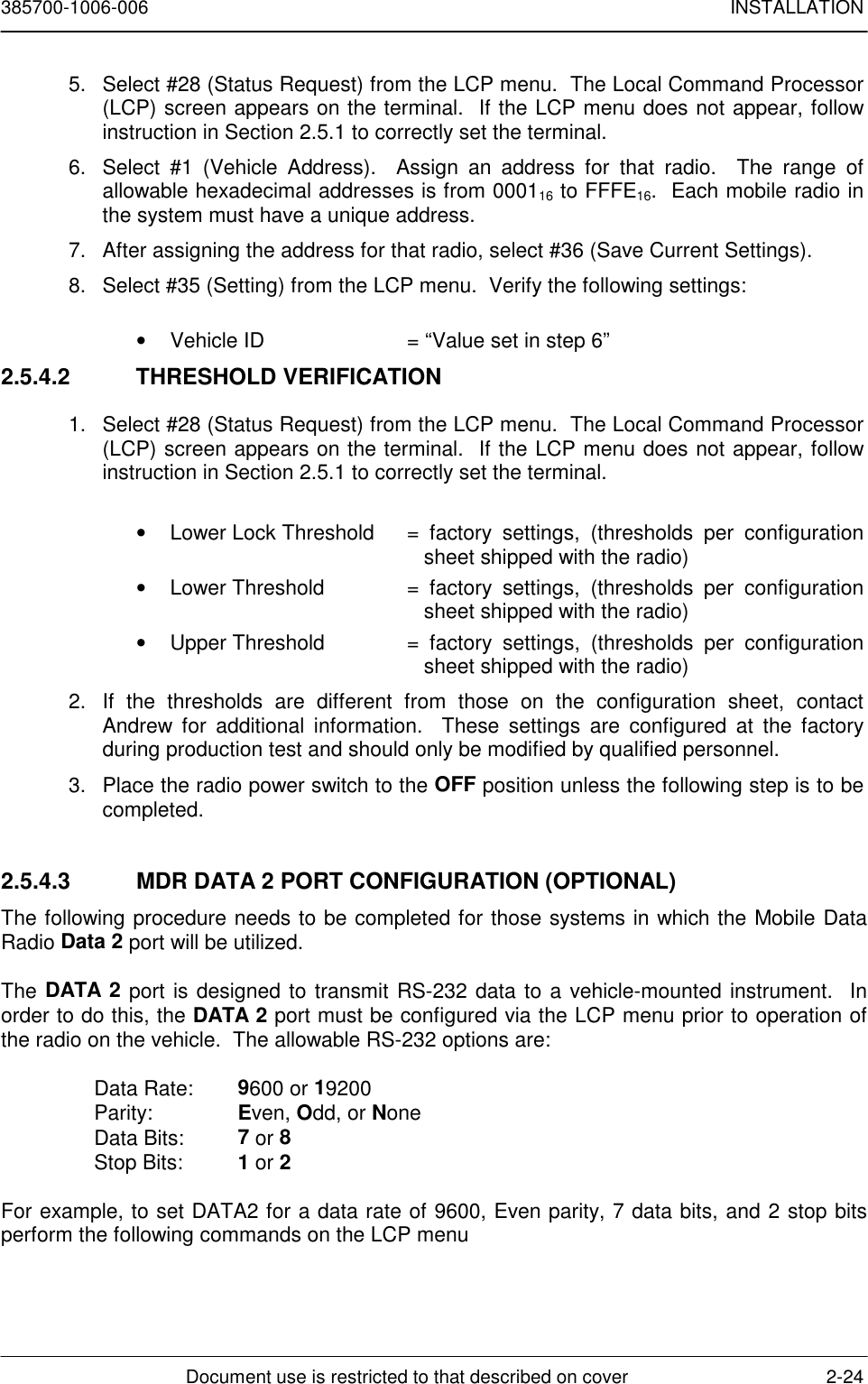
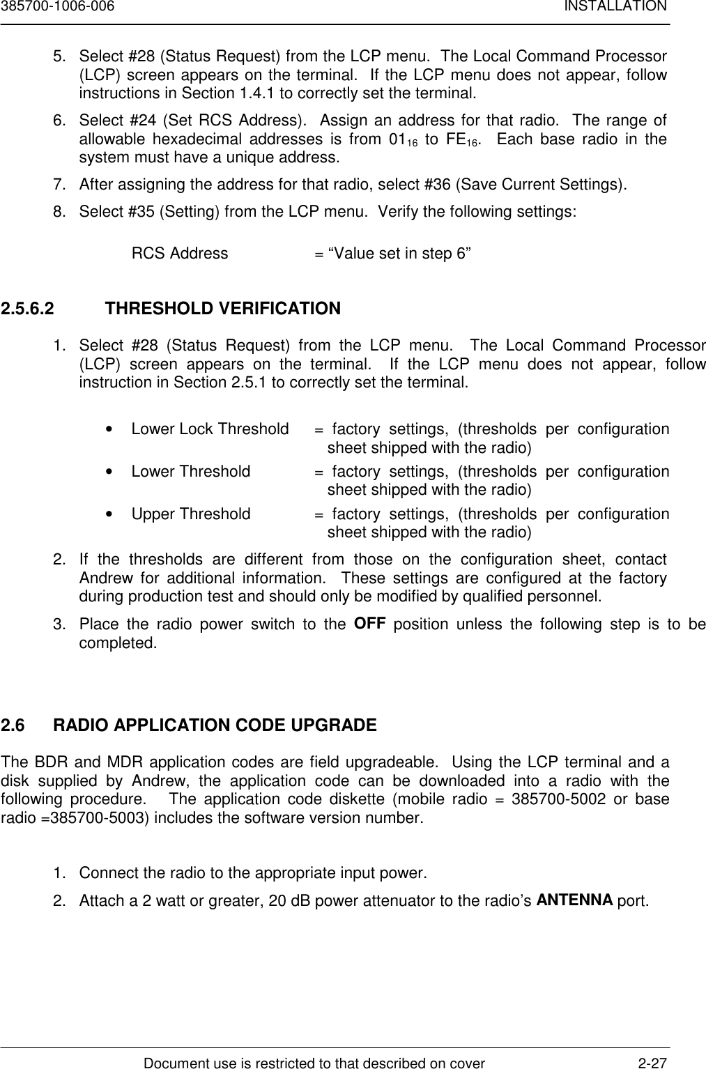
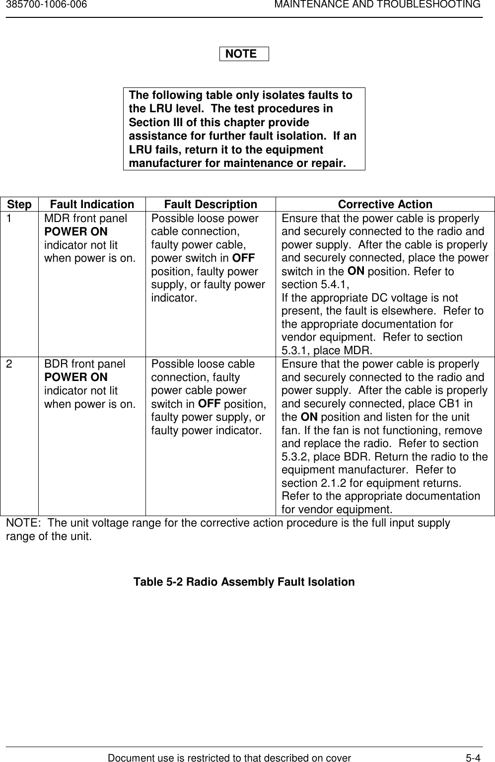
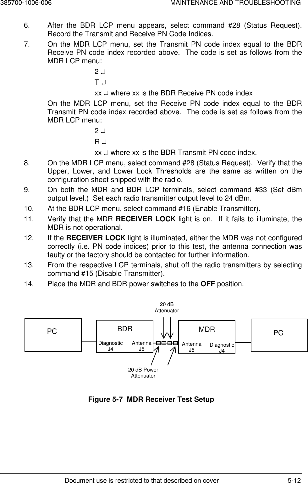
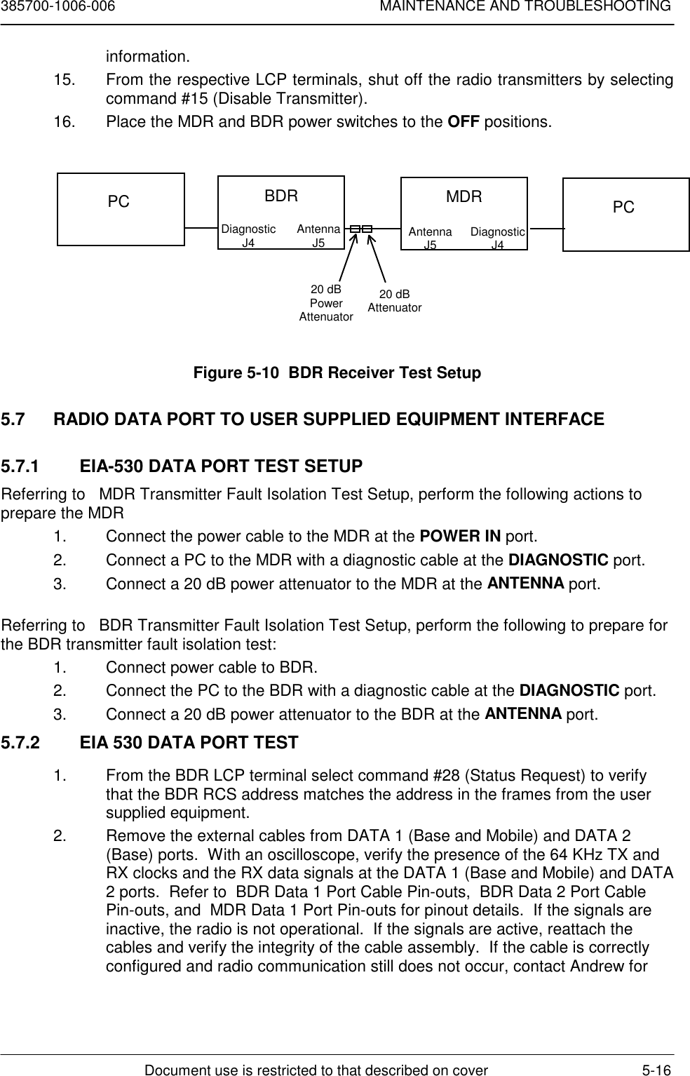
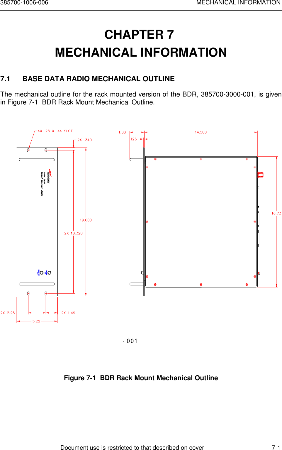
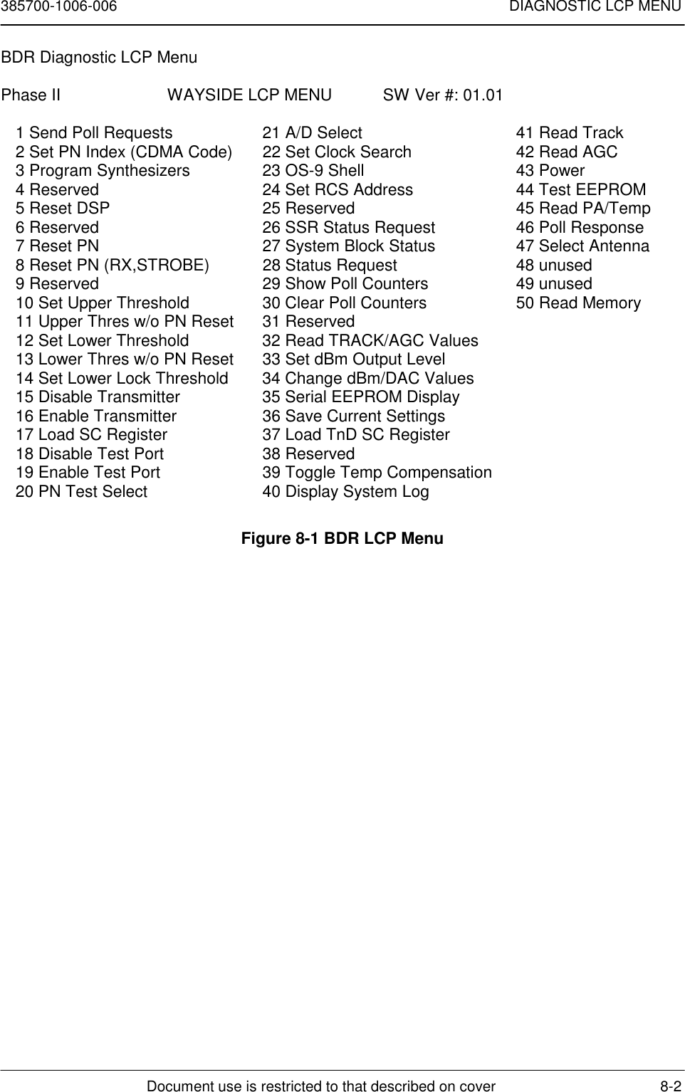
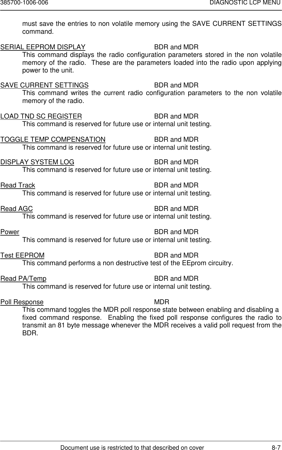
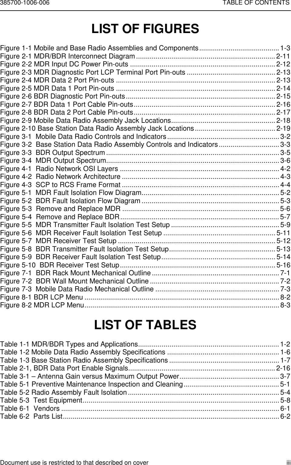
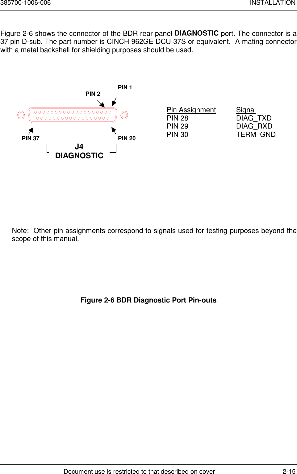
![385700-1006-006 INSTALLATIONDocument use is restricted to that described on cover 2-283. Connect cabling between the radio DIAGNOSTIC port and dumb terminal, an IBMPC with Procomm™ Software, or any communications software that supportsVT100 emulation.4. Place the radio power switch to the ON position.9. Upon completion of the self-test, the LCP terminal will appear as shown below.**** Starting RCS Self Test... ****68302 RAM Test: PASSED or FAILEDFLASH TEST: PASSED or FAILEDATMEL AT59C11 EEPROM Test: PASSED or FAILED68302 SCC1 Internal Loopback Test: PASSED or FAILED68302 SCC2 Internal Loopback Test: PASSED or FAILED68302 SCC3 Internal Loopback Test: PASSED or FAILEDDUART 68681 Local Loopback Test: PASSED or FAILED**** RCS Self Test Complete ****Automatically running RCS ... Press 3 <CRs> to abort.10. Press the <ENTER> key 3 times. This should bring up the RCS Maintenance andUpgrade menuRCS Maintenance and Upgrade Menu[0] Download RCS Software[1] Download Board Level Test Software[2] Download Flash Download Software[3] Download Microwave OS-9 Kernel[4] Download Power-on Self Test[5] Download Boot[6] Run Board Level Test[7] Run RCS[8] Run RCS, without an SCP[9] Display Software Version #’s[10]Reset Radio Enter Option [0 - 10]:11. Select #0 (Download RCS Software). From the terminal computer communicationsprogram select the SEND FILE function with RAW ASCII as the protocol. Selectthe drive and directory where the application code diskette is located.12. After the download is complete, select #9 from the RCS Maintenance and UpgradeMenu. Verify that the application code version corresponds to the version loadedin the previous step. Record the software versions on the configuration sheet if](https://usermanual.wiki/Andrew/MDL2400MDR.user-manual/User-Guide-100941-Page-37.png)
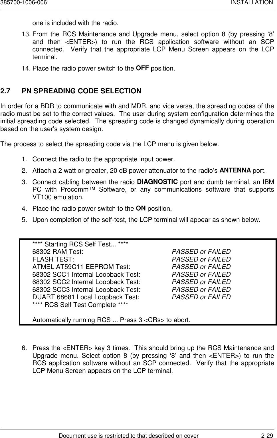
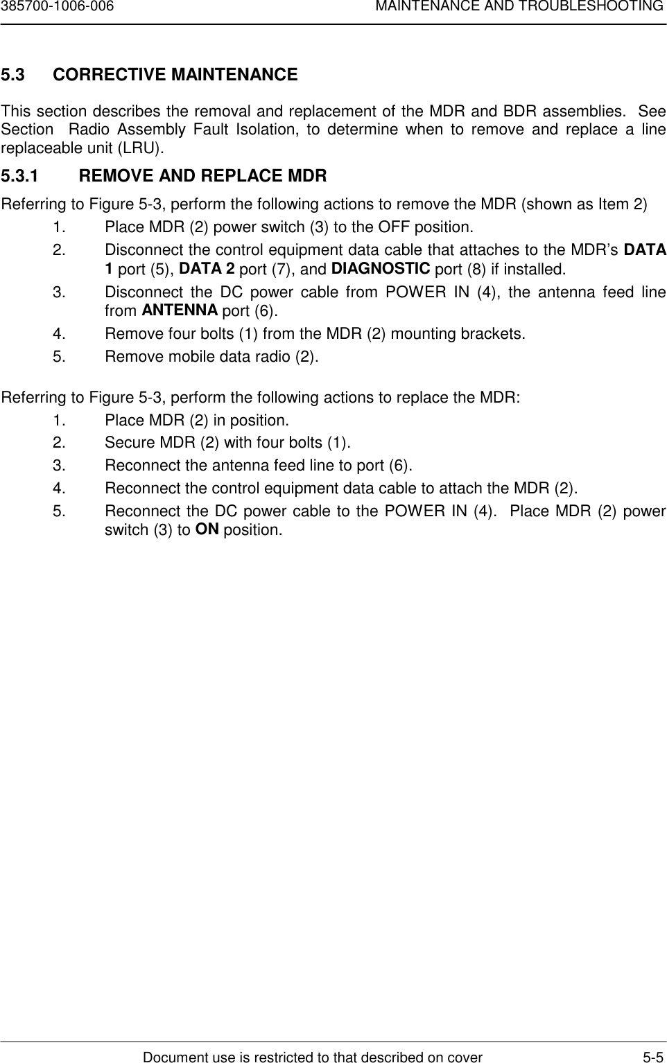
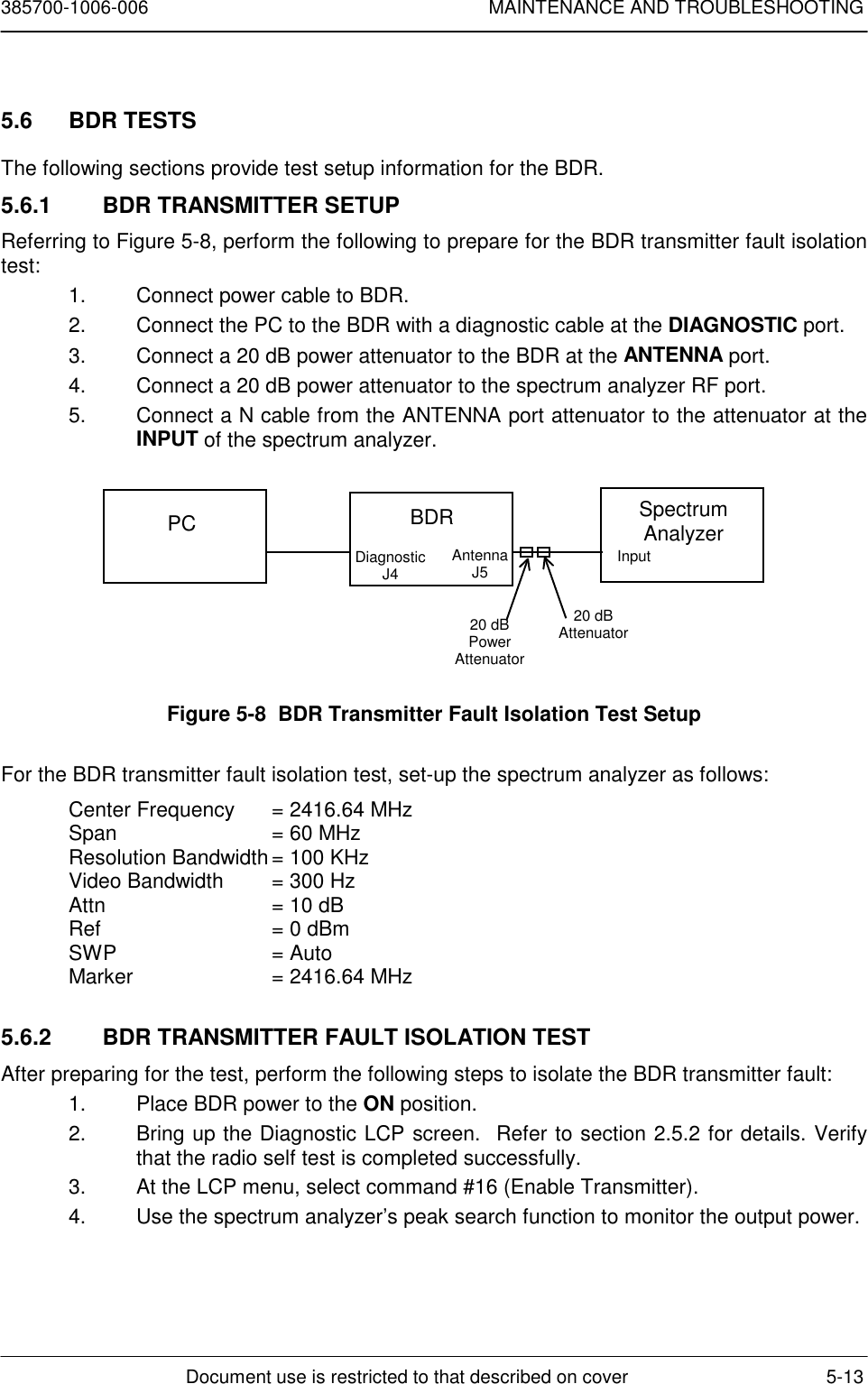
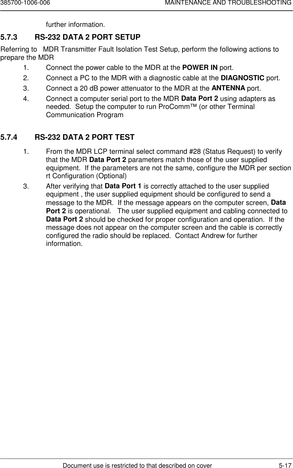
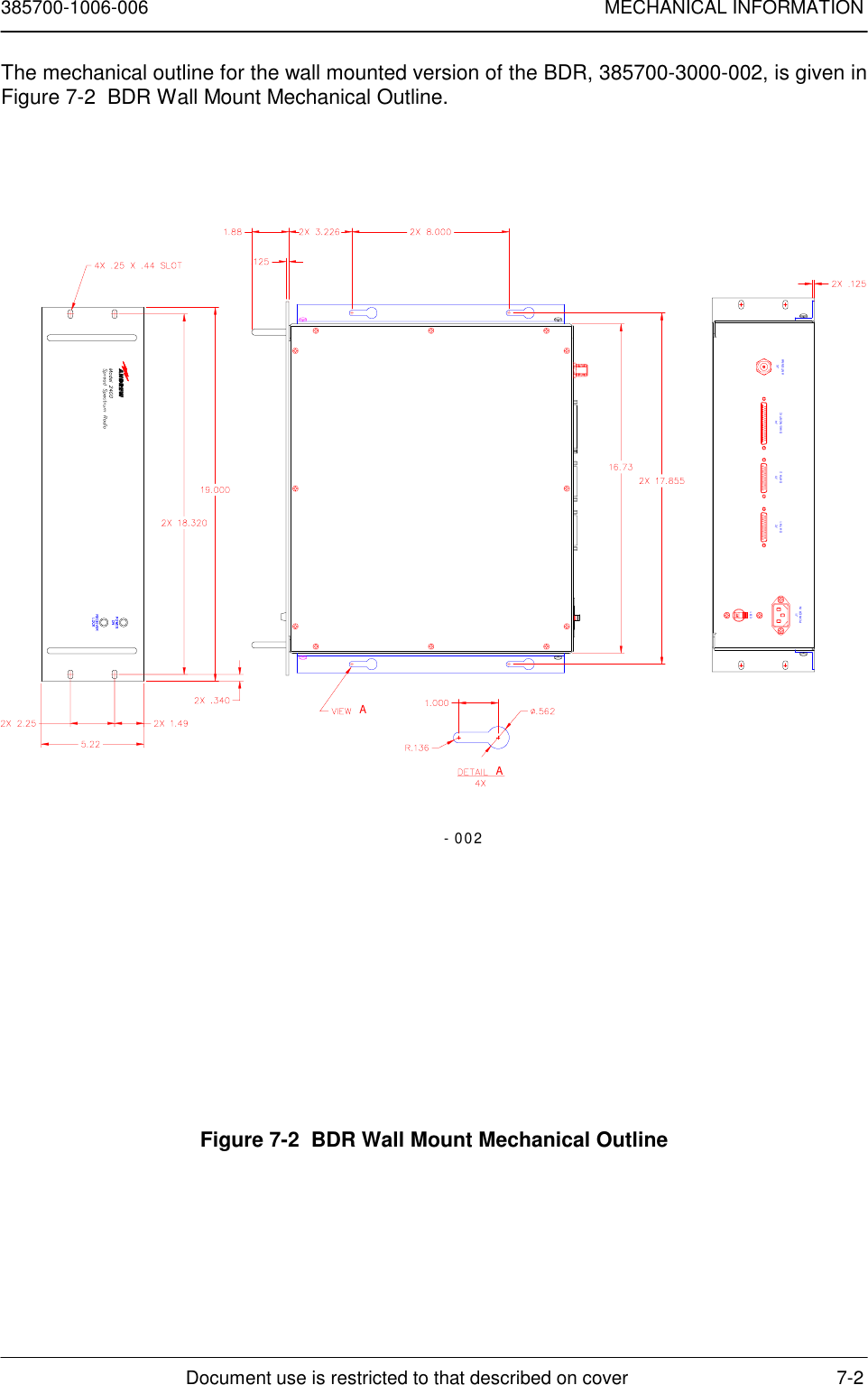
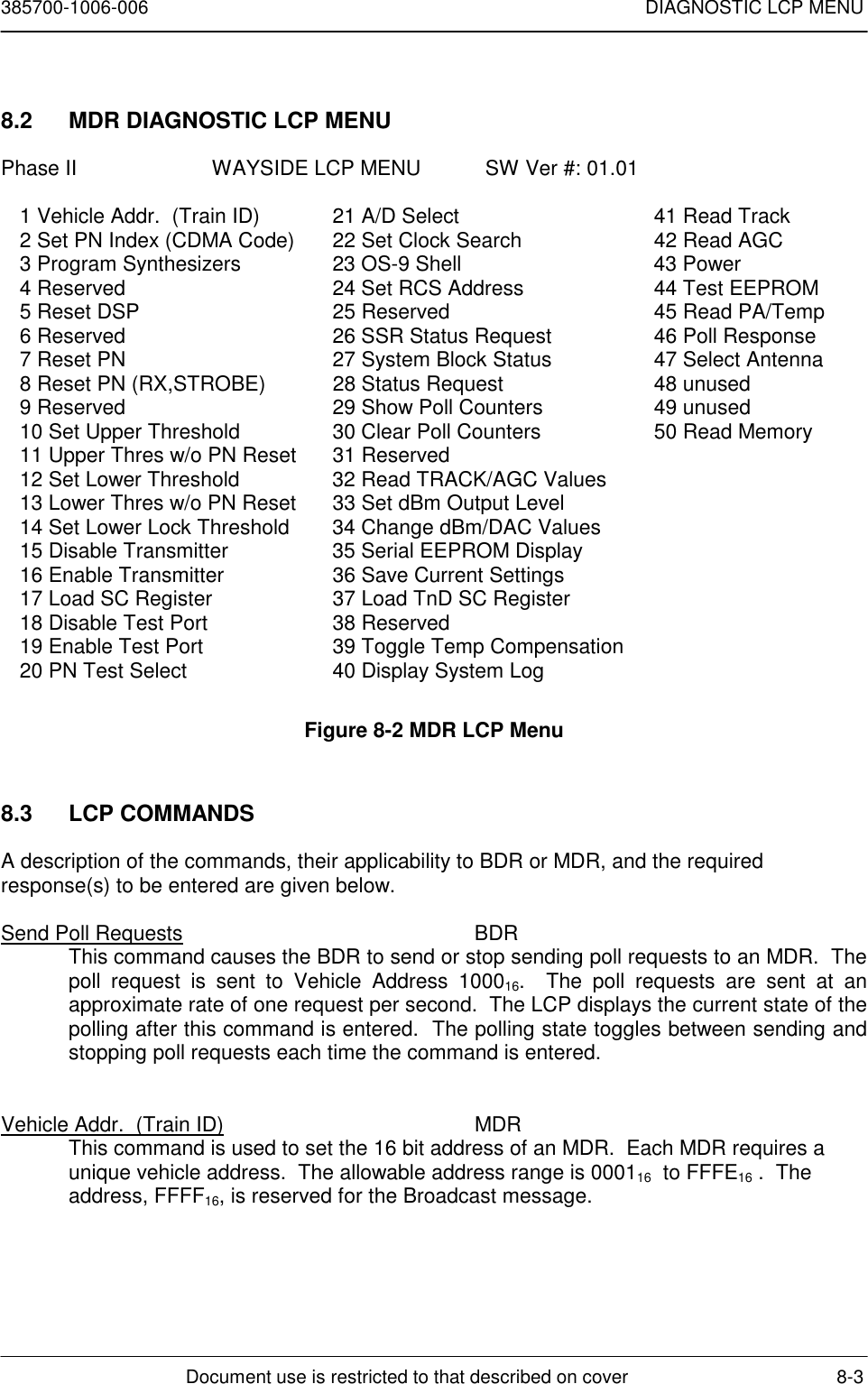
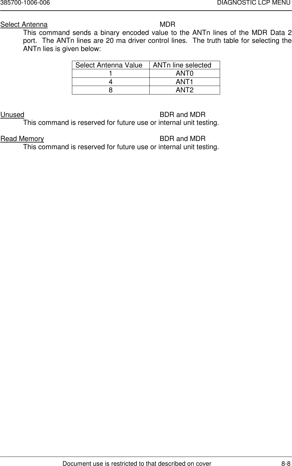
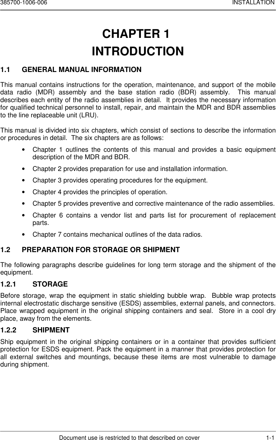
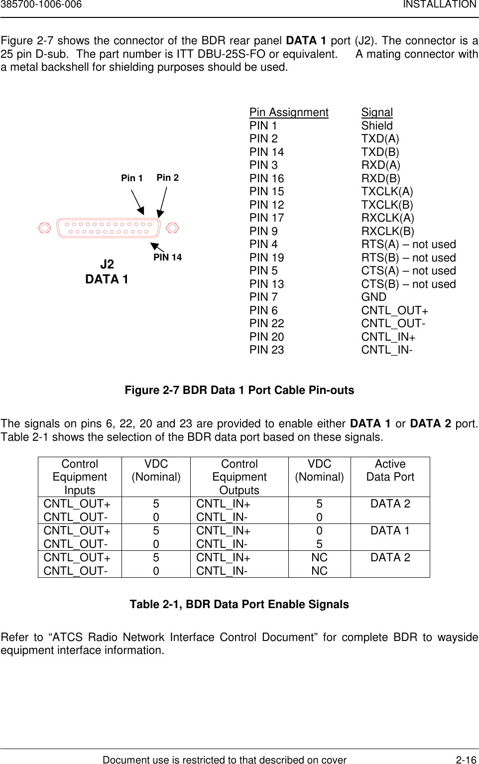
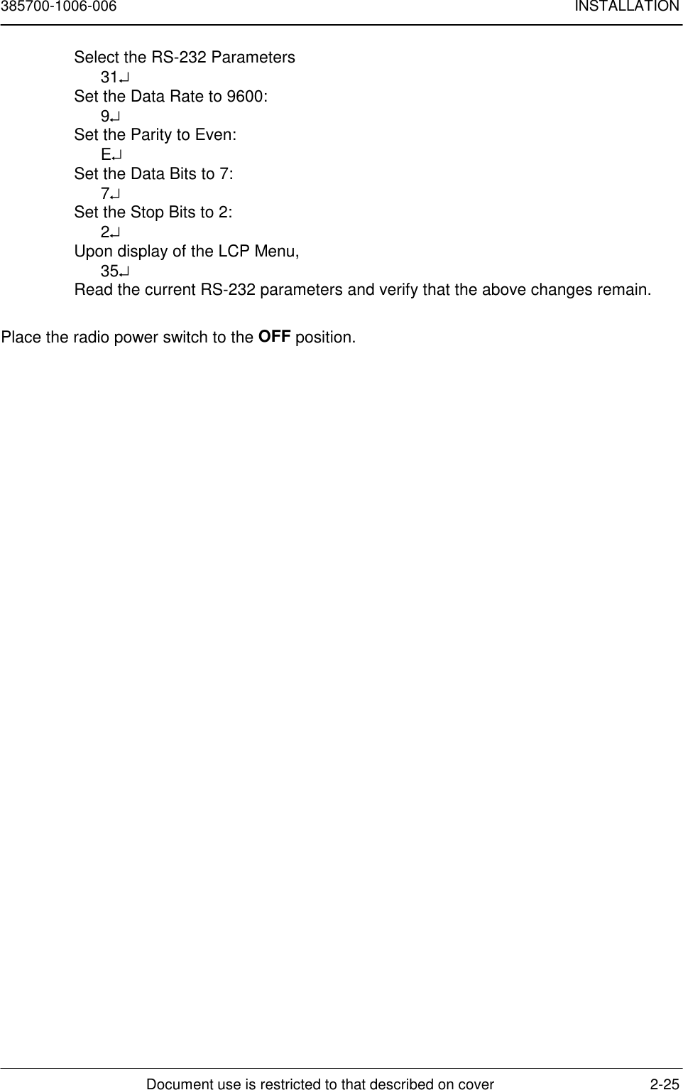
![385700-1006-006 INSTALLATIONDocument use is restricted to that described on cover 2-30RCS Maintenance and Upgrade Menu[0] Download RCS Software[1] Download Board Level Test Software[2] Download Flash Download Software[3] Download Microwave OS-9 Kernel[4] Download Power-on Self Test[5] Download Boot[6] Run Board Level Test[7] Run RCS[8] Run RCS, without an SCP[9] Display Software Version #’s[10]Reset Radio Enter Option [0 - 10]:7. After the LCP menu appears, select #2 to Set PN Code Index. The user will beprompted to enter T (transmitter) or R (receiver) to choose which code to set.Choose T (transmitter) and press <ENTER>. The user is then prompted to selecta number that corresponds to the PN spreading code to be selected. The range ofallowable values is listed on the screen as part of the user prompt. This process isrepeated to set the receiver code.8. Place the radio power switch to the OFF position.2.8 ANTENNA AND CABLE INSTALLATIONAfter integrating the MDRs and BDRs into the RCS, ensure that all cabling is securely andproperly attached to each unit. The cable assemblies attached to the individual radio dataports must be properly shielded. Connect the antenna cable to the radios. Place the MDRand BDR power switches to the up position (ON). Verify that each unit lights its POWER ONindicator. Refer to Mobile Data Radio Controls and Indicators, and Base Station DataRadio Assembly Controls and Indicators.](https://usermanual.wiki/Andrew/MDL2400MDR.user-manual/User-Guide-100941-Page-39.png)