Andrew MDL2400MDR Mobile Data Radio User Manual OPERATION AND MAINTENANCE MANUAL
Andrew Corporation Mobile Data Radio OPERATION AND MAINTENANCE MANUAL
Andrew >
Contents
- 1. Operation and Maintenance
- 2. user manual
user manual

OPERATION AND MAINTENANCE MANUAL
For the
MOBILE DATA RADIO AND
BASE DATA RADIO
MANUAL NO. 385700-1006
REVISION 6
The information set forth in this document and all rights in and to inventions
disclosed herein, and patents which might be granted thereon disclosing,
employing or covering the materials, methods, techniques or apparatus
described herein are the exclusive property of Andrew Corporation.
This document is an operation and maintenance manual. No disclosure or
reproduction of the information or drawings shall be made of any other
purpose without the prior written consent of Andrew. Use of the information
contained herein to fabricate or assemble any item in whole or in part is
expressly prohibited.
2601 Telecom Parkway, Richardson, Texas 75082-3521
TEL (972) 952-9700 FAX (972) 952-0000

385700-1006-006 FCC REQUIREMENTS
Document use is restricted to that described on cover A
SAFETY SUMMARY
High voltage is used in the operation of
this equipment. Death on contact may
result, if personnel fail to observe the
following safety precautions:
• Do not be misled by the term “Low Voltage.” Potentials as low as 50 Volts may cause
death under adverse conditions.
• Do not crush, puncture, disassemble or otherwise mutilate batteries. Leaking batteries
can cause serious damage to equipment and injury to personnel.
• Do not remove covers or access plates on the equipment, unless you are authorized to do
so.
• Do not work on electronic equipment unless there is another person nearby who is familiar
with the operation of the equipment and is trained in administering first aid.
• Whenever possible, disconnect the equipment from the power source before beginning
maintenance.
• To prevent electrical shock or damage to the equipment, do not operate it until you
thoroughly understand the operation and function of all controls, indicators, and
connectors.
• Turn off all power to the equipment before replacing any fuses.
FIRST AID
In case of electrical shock:
• Do not try to pull or grab the individual.
• If possible, turn off the electrical power.
• If you cannot turn off the electrical power, pull, push, or lift the person to safety using a dry
wooden pole, a dry rope, or some other insulating material.
• Send for help as soon as possible.
• After the injured person is no longer in contact with the source of electrical shock, move
the person a short distance away and immediately administer first aid and artificial
resuscitation as required.

385700-1006-006 FCC REQUIREMENTS
Document use is restricted to that described on cover B
This device complies with Part 15 of the FCC rules. Operation is
subject to the following two conditions:
(1) This device may not cause harmful interference, and
(2) This device must accept any interference received, including
interference that may cause undesired operation
The Base Data Radio and Mobile Data Radios are unlicensed
devices operating under the conditions of FCC part 15
regulations. This equipment is intended to be installed and
operated by professional parties. It is the responsibility of those
parties to insure that the equipment is operated in compliance
with the applicable FCC part 15 specifications and the
requirements contained in this document.
WARNING
WARNING

385700-1006-006 FCC REQUIREMENTS
Document use is restricted to that described on cover C
LIST OF ABBREVIATIONS AND ACRONYMS
All abbreviations/acronyms used in this
manual, other than those listed on this
page, are used per MIL-STD-12D.
BDR Base Data Radio
CDMA Code Division Multiple Access
EEPROM Electrically Erasable Programmable Read Only Memory
ESDS Electrostatic Discharge Sensitive
LCP Local Command Processor
LRU Line Replaceable Unit
MDR Mobile Data Radio
PC Personal Computer
PN Pseudo Noise
RBW Resolution Bandwidth
RCS Radio Communication Subsystem
SSR Spread Spectrum Radio
TDMA Time Division Multiple Access
VBW Video Bandwidth
NOTE

385700-1006-006 LIST OF REFERENCE DOCUMENTS
Document use is restricted to that described on cover D
LIST OF REFERENCE DOCUMENTS
Interface Control Document
Drawings:
Assembly, Mobile Data Radio 3385700-1000
Cable Assembly:
Diagnostic, MDR 385700-1805
Power Out, MDR 385700-1806
Power In, MDR 385700-1807
Data, MDR 385700-1808
RCS to Diagnostic, MDR 385700-1811
RCS to RS232, MDR 385700-1812
RCS to SCP, MDR 385700-1813
Assembly, Base Data Radio 385700-3000
Cable Assembly:
Diagnostic, BDR 385700-3805
Power, BDR 385700-3806
Data, BDR 385700-3808
RCS to Diagnostic. BDR 385700-3811
RCS to SCP1, BDR 385700-3812
RCS to SCP2, BDR 385700-3813

385700-1006-006 TABLE OF CONTENTS
Document use is restricted to that described on cover i
TABLE OF CONTENTS
CHAPTER 1............................................................................................................................................ 1-1
1.1 GENERAL MANUAL INFORMATION........................................................................................ 1-1
1.2 PREPARATION FOR STORAGE OR SHIPMENT.................................................................... 1-1
1.2.1 Storage.............................................................................................................................. 1-1
1.2.2 Shipment ........................................................................................................................... 1-1
1.3 DESCRIPTION OF EQUIPMENT.............................................................................................. 1-2
1.3.1 Type of Equipment ............................................................................................................ 1-2
1.3.2 Purpose of the Equipment................................................................................................. 1-2
1.4 LOCATIONS AND DESCRIPTIONS OF MAJOR COMPONENTS........................................... 1-2
1.4.1 Mobile Data Radio Assembly ............................................................................................ 1-4
1.4.2 Base Station Radio Assembly........................................................................................... 1-4
1.5 EQUIPMENT CHARACTERISTICS........................................................................................... 1-5
1.5.1 Power and Utility Requirements ........................................................................................ 1-5
1.5.2 Environmental Information ................................................................................................ 1-5
CHAPTER 2............................................................................................................................................ 2-8
2.1 INSTALLING THE RADIO EQUIPMENT................................................................................... 2-8
2.1.1 Unpacking and Inspection................................................................................................. 2-8
2.1.2 Proper Installation of Units ................................................................................................ 2-8
2.2 INTERCONNECTIONS.............................................................................................................. 2-8
2.2.1 Mobile Configuration Interconnection................................................................................ 2-9
2.2.2 Wayside Configuration Interconnection ............................................................................ 2-9
2.3 CABLE AND GROUND REQUIREMENTS.............................................................................. 2-10
2.3.1 Connector Pin-outs.......................................................................................................... 2-12
2.4 COMPONENT JACK LOCATIONS ......................................................................................... 2-17
2.4.1 Mobile Data Radio Jack Locations.................................................................................. 2-17
2.4.2 Base Station Data Radio Jack Locations ........................................................................ 2-18
2.5 INITIAL PREPARATION FOR USE......................................................................................... 2-20
2.5.1 Setting up Communications with the LCP Terminal Port ................................................ 2-20
2.5.2 Diagnostic/LCP Terminals............................................................................................... 2-21
2.5.3 Vehicle LCP Menu...........................................................................................................2-23
2.5.4 MDR Initial Operational Adjustments .............................................................................. 2-23
2.5.5 Wayside LCP Menu......................................................................................................... 2-26
2.5.6 BDR Initial Operational Adjustments............................................................................... 2-26
2.6 RADIO APPLICATION CODE UPGRADE............................................................................... 2-27
2.7 PN SPREADING CODE SELECTION..................................................................................... 2-29
2.8 ANTENNA AND CABLE INSTALLATION................................................................................ 2-30
CHAPTER 3............................................................................................................................................ 3-1
3.1 CONTROLS AND INDICATORS............................................................................................... 3-1
3.1.1 MDR Controls and Indicators ............................................................................................ 3-1
3.1.2 BDR Controls and Indicators............................................................................................. 3-1
3.2 STARTUP AND SHUTDOWN PRODECURES......................................................................... 3-4
3.2.1 MDR Startup...................................................................................................................... 3-4
3.2.2 BDR Startup ...................................................................................................................... 3-4
3.2.3 Normal Operation.............................................................................................................. 3-4
3.2.4 Shutdown .......................................................................................................................... 3-4
3.3 OUTPUT POWER SETTINGS .................................................................................................. 3-7
3.4 ANTENNA PLACEMENT........................................................................................................... 3-7
CHAPTER 4............................................................................................................................................ 4-1
4.1 FUNCTIONAL DESCRIPTION OF EQUIPMENT...................................................................... 4-1
4.1.1 Mobile Data Radio and Base Data Radio.......................................................................... 4-1
4.1.2 Radio Network Architecture............................................................................................... 4-2

385700-1006-006 TABLE OF CONTENTS
Document use is restricted to that described on cover ii
4.1.3 MDR/BDR Communications Handling .............................................................................. 4-5
4.1.4 PN SPREADING CODES ................................................................................................. 4-5
4.1.5 ANTENNA SWITCHING CONTROLS .............................................................................. 4-6
CHAPTER 5............................................................................................................................................ 5-1
5.1 PREVENTIVE MAINTENANCE, INSPECTION, AND CLEANING............................................ 5-1
5.2 TROUBLESHOOTING............................................................................................................... 5-1
5.3 CORRECTIVE MAINTENANCE ................................................................................................ 5-5
5.3.1 Remove and Replace MDR............................................................................................... 5-5
5.3.2 Remove and Replace BDR ............................................................................................... 5-6
5.4 TEST PROCEDURES ............................................................................................................... 5-8
5.4.1 MDR Power Verification .................................................................................................... 5-8
5.4.2 BDR Power Verification.....................................................................................................5-8
5.5 MDR TESTS .............................................................................................................................. 5-9
5.5.1 MDR Transmitter Test Setup ............................................................................................ 5-9
5.5.2 MDR Transmitter Fault Isolation Test ............................................................................. 5-10
5.5.3 MDR Only Receiver Fault Isolation Test Setup............................................................... 5-10
5.5.4 MDR Only Receiver Fault Isolation Test ......................................................................... 5-11
5.5.5 MDR/BDR Receiver Test Setup...................................................................................... 5-11
5.6 BDR TESTS............................................................................................................................. 5-13
5.6.1 BDR Transmitter Setup ................................................................................................... 5-13
5.6.2 BDR Transmitter Fault Isolation Test.............................................................................. 5-13
5.6.3 BDR Only Receiver Fault Isolation Test Setup ............................................................... 5-14
5.6.4 BDR Only Receiver Fault Isolation Test.......................................................................... 5-14
5.6.5 BDR/MDR Receiver Test Setup...................................................................................... 5-15
5.7 RADIO DATA PORT TO USER SUPPLIED EQUIPMENT INTERFACE ................................ 5-16
5.7.1 EIA-530 Data Port Test Setup......................................................................................... 5-16
5.7.2 EIA 530 Data Port Test ................................................................................................... 5-16
5.7.3 RS-232 Data 2 Port Setup............................................................................................... 5-17
5.7.4 RS-232 Data 2 Port Test................................................................................................. 5-17
CHAPTER 6............................................................................................................................................ 6-1
6.1 PARTS LIST .............................................................................................................................. 6-1
CHAPTER 7............................................................................................................................................ 7-1
7.1 BASE DATA RADIO MECHANICAL OUTLINE ......................................................................... 7-1
CHAPTER 8............................................................................................................................................ 8-1
8.1 DIAGNOSTIC MENU................................................................................................................. 8-1
8.2 MDR DIAGNOSTIC LCP MENU................................................................................................ 8-3
8.3 LCP COMMANDS...................................................................................................................... 8-3

385700-1006-006 TABLE OF CONTENTS
Document use is restricted to that described on cover iii
LIST OF FIGURES
Figure 1-1 Mobile and Base Radio Assemblies and Components......................................... 1-3
Figure 2-1 MDR/BDR Interconnect Diagram....................................................................... 2-11
Figure 2-2 MDR Input DC Power Pin-outs ..........................................................................2-12
Figure 2-3 MDR Diagnostic Port LCP Terminal Port Pin-outs .............................................2-13
Figure 2-4 MDR Data 2 Port Pin-outs ................................................................................. 2-13
Figure 2-5 MDR Data 1 Port Pin-outs ................................................................................. 2-14
Figure 2-6 BDR Diagnostic Port Pin-outs............................................................................2-15
Figure 2-7 BDR Data 1 Port Cable Pin-outs........................................................................ 2-16
Figure 2-8 BDR Data 2 Port Cable Pin-outs........................................................................ 2-17
Figure 2-9 Mobile Data Radio Assembly Jack Locations..................................................... 2-18
Figure 2-10 Base Station Data Radio Assembly Jack Locations......................................... 2-19
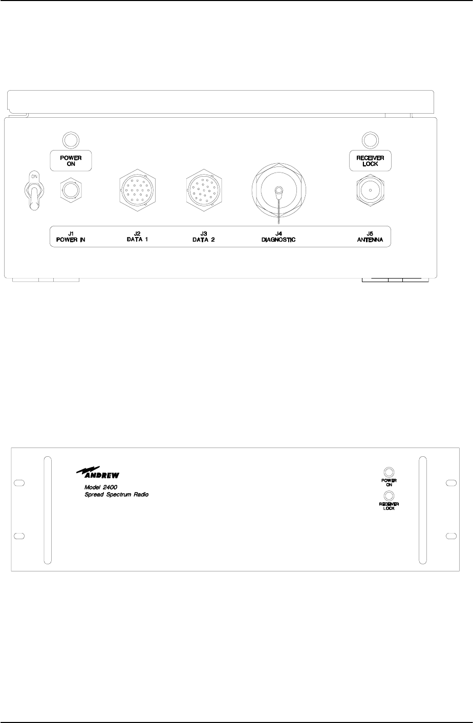
Figure 3-1 Mobile Data Radio Controls and Indicators.........................................................3-2
Figure 3-2 Base Station Data Radio Assembly Controls and Indicators...............................3-3
Figure 3-3 BDR Output Spectrum........................................................................................3-5
Figure 3-4 MDR Output Spectrum........................................................................................3-6
Figure 4-1 Radio Network OSI Layers ................................................................................. 4-2
Figure 4-2 Radio Network Architecture ................................................................................4-3
Figure 4-3 SCP to RCS Frame Format ................................................................................4-4
Figure 5-1 MDR Fault Isolation Flow Diagram......................................................................5-2
Figure 5-2 BDR Fault Isolation Flow Diagram ......................................................................5-3
Figure 5-3 Remove and Replace MDR ................................................................................5-6
Figure 5-4 Remove and Replace BDR.................................................................................5-7
Figure 5-5 MDR Transmitter Fault Isolation Test Setup .......................................................5-9
Figure 5-6 MDR Receiver Fault Isolation Test Setup ......................................................... 5-11
Figure 5-7 MDR Receiver Test Setup ................................................................................ 5-12
Figure 5-8 BDR Transmitter Fault Isolation Test Setup...................................................... 5-13
Figure 5-9 BDR Receiver Fault Isolation Test Setup..........................................................5-14
Figure 5-10 BDR Receiver Test Setup...............................................................................5-16
Figure 7-1 BDR Rack Mount Mechanical Outline................................................................. 7-1
Figure 7-2 BDR Wall Mount Mechanical Outline ..................................................................7-2
Figure 7-3 Mobile Data Radio Mechanical Outline ...............................................................7-3
Figure 8-1 BDR LCP Menu ................................................................................................... 8-2
Figure 8-2 MDR LCP Menu................................................................................................... 8-3
LIST OF TABLES
Table 1-1 MDR/BDR Types and Applications........................................................................1-2
Table 1-2 Mobile Data Radio Assembly Specifications .........................................................1-6
Table 1-3 Base Station Radio Assembly Specifications ........................................................1-7
Table 2-1, BDR Data Port Enable Signals........................................................................... 2-16
Table 3-1 – Antenna Gain versus Maximum Output Power...................................................3-7
Table 5-1 Preventive Maintenance Inspection and Cleaning.................................................5-1
Table 5-2 Radio Assembly Fault Isolation.............................................................................5-4
Table 5-3 Test Equipment....................................................................................................5-8
Table 6-1 Vendors ............................................................................................................... 6-1
Table 6-2 Parts List..............................................................................................................6-2

385700-1006-006 TABLE OF CONTENTS
Document use is restricted to that described on cover iv

385700-1006-006 INSTALLATION
Document use is restricted to that described on cover 1-1
CHAPTER 1
INTRODUCTION
1.1 GENERAL MANUAL INFORMATION
This manual contains instructions for the operation, maintenance, and support of the mobile
data radio (MDR) assembly and the base station radio (BDR) assembly. This manual
describes each entity of the radio assemblies in detail. It provides the necessary information
for qualified technical personnel to install, repair, and maintain the MDR and BDR assemblies
to the line replaceable unit (LRU).
This manual is divided into six chapters, which consist of sections to describe the information
or procedures in detail. The six chapters are as follows:
• Chapter 1 outlines the contents of this manual and provides a basic equipment
description of the MDR and BDR.
• Chapter 2 provides preparation for use and installation information.
• Chapter 3 provides operating procedures for the equipment.
• Chapter 4 provides the principles of operation.
• Chapter 5 provides preventive and corrective maintenance of the radio assemblies.
• Chapter 6 contains a vendor list and parts list for procurement of replacement
parts.
• Chapter 7 contains mechanical outlines of the data radios.
1.2 PREPARATION FOR STORAGE OR SHIPMENT
The following paragraphs describe guidelines for long term storage and the shipment of the
equipment.
1.2.1 STORAGE
Before storage, wrap the equipment in static shielding bubble wrap. Bubble wrap protects
internal electrostatic discharge sensitive (ESDS) assemblies, external panels, and connectors.
Place wrapped equipment in the original shipping containers and seal. Store in a cool dry
place, away from the elements.
1.2.2 SHIPMENT
Ship equipment in the original shipping containers or in a container that provides sufficient
protection for ESDS equipment. Pack the equipment in a manner that provides protection for
all external switches and mountings, because these items are most vulnerable to damage
during shipment.

385700-1006-006 INSTALLATION
Document use is restricted to that described on cover 1-2
1.3 DESCRIPTION OF EQUIPMENT
The Radio Communications Network consists of Base and Mobile Radio Communication
Systems (RCS). The Base RCS includes Base Data Radios (BDR) connected to wayside
Control Equipment. The Mobile RCS includes Mobile Data Radios connected to Control
Equipment on board the vehicle. The Radio Communications Systems provide bi-directional
communications. The systems operate in a combined Time Division Multiple Access (TDMA)
and Code Division Multiple Access (CDMA) environment.
The Mobile Data Radio (MDR) and Base Data Radios (BDR) in the technical manual are
Spread Spectrum non-licensed RF transceivers.
1.3.1 TYPE OF EQUIPMENT
The MDR and BDR are non-licensed spread spectrum transceivers that operate in the ISM
2400-2483.5 MHz frequency band. Antennas connected to MDR and BDR may come from
different vendors. Antennas should support the 2400-2483 MHz frequency band, be
compliant with FCC part 15 regulations, and are to be installed by professional parties.
Refer to Table 1-1 MDR/BDR Types and Applications. The following table contains part
numbers for different versions of MDR and BDR.
Part No. Type Application
385700-1000-001 MDR Input Voltage 18-32 VDC
385700-1000-002 MDR Input Voltage 21-56 VDC
385700-3000-001 BDR Rack Mounted
385700-3000-002 BDR Wall Mounted
385700-3000-003 BDR Pole Mounted
Table 1-1 MDR/BDR Types and Applications
1.3.2 PURPOSE OF THE EQUIPMENT
The radio provides a bi-directional communication link between the wayside and the vehicle
control equipment. The wayside control equipment generates data and sends it to the BDR.
The BDR transmits data over the radio channel to the appropriate MDR. The MDR
communicates with the vehicle control equipment, obtains the response, and transmits it to
the BDR via the RF link.
1.4 LOCATIONS AND DESCRIPTIONS OF MAJOR COMPONENTS
Refer to Figure 1-1 Mobile and Base Radio Assemblies and Components. The following
paragraphs contain the complete descriptions and locations of the mobile data radio and base
data radio.
385700-1006-006 INSTALLATION
Document use is restricted to that described on cover 1-3
Mobile Data Radio
Base Data Radio
Figure 1-1 Mobile and Base Radio Assemblies and Components

385700-1006-006 INSTALLATION
Document use is restricted to that described on cover 1-4
1.4.1 MOBILE DATA RADIO ASSEMBLY
The mobile data radio (MDR) uses direct sequence spread spectrum modulation techniques.
The MDR transmits at a center frequency of 2467.84 MHz. and receives at a center frequency
of 2416.64 MHz.
The MDR communicates with the vehicle control equipment across an EIA 530 (RS-422)
interface at J2. The MDR can also send messages to external equipment via an RS-232
interface at J3. An operator can also communicate with the MDR through the diagnostic port
across an RS-232 interface (refer to paragraph 2.5.2) at J4. This interface is referred to as the
Local Command Processor (LCP) terminal and is used to load user supplied parameters into
the radio’s non-volatile memory when the radio is initially delivered to the customer. This RS-
232 interface is not used during normal operation of the radio. The MDR receives power from
a nominal 28 VDC (or a nominal 36 VDC depending on application), power source at J1.
Refer to Table 1-2 Mobile Data Radio Assembly Specifications.
1.4.2 BASE STATION RADIO ASSEMBLY
The base data radio (BDR), like the MDR, is a spread spectrum transceiver. The BDR
transmits at a center frequency of 2416.64 MHz frequency and receives at a center frequency
of 2457.84 MHz band. Refer to Table 1-3 Base Station Radio Assembly Specifications. The
BDR communicates across an EIA 530 (RS-422) interface to the wayside control equipment
at J2 or J3 (see Figure 2-10). An operator can also communicate with the BDR through the
diagnostic port, J4, across an RS-232 interface (refer to paragraph 2.5.2). This interface is
referred to as the Local Command Processor (LCP) terminal and is used to load user supplied
parameters into the radio’s non-volatile memory when the radio is initially delivered to the
customer. This RS-232 interface is not used during normal operation of the radio. The BDR
receives its AC input power at J1. Tables 1-2 through 1-3 contain the specifications for the
MDR and BDR. The tables include characteristics and specifications in three categories:
technical, environmental, and physical.
Fi
g
ure 1-2 Transmitter Block Dia
g
ram

385700-1006-006 INSTALLATION
Document use is restricted to that described on cover 1-5
1.5 EQUIPMENT CHARACTERISTICS
1.5.1 POWER AND UTILITY REQUIREMENTS
The MDR requires a nominal 28 VDC (or a nominal 36 VDC depending on application) power
source to operate. Refer to Table 1-2 Mobile Data Radio Assembly Specifications for more
detailed information. The BDR requires nominally 120 VAC to operate. Refer to Table 1-3
Base Station Radio Assembly Specifications, for more detailed information.
1.5.2 ENVIRONMENTAL INFORMATION
The MDR assembly can withstand the shock and vibration associated with mobile
environments. It is contained in a weatherproof enclosure. Refer to Table 1-2 Mobile Data
Radio Assembly Specifications, for more detailed information.
The BDR assembly is designed for an environment away from the elements. It can be rack-
mounted, or wall mounted. Refer to Table 1-3 Base Station Radio Assembly Specifications,
for more detailed information. There are provisions for the BDR assembly to be delivered in a
pole-mounted configuration. Its environmental characteristics will be similar to MDR.

385700-1006-006 INSTALLATION
Document use is restricted to that described on cover 1-6
Transmitter
Transmitter Center Frequency 2467.84 MHz
Output Power (+24 dBm linear) – adjustable
Transmitter Duty Cycle Up to 100% continuous operation
Modulation Gaussian Phase Shift Keying
Receiver
Receiver Center Frequency 2416.64 MHz
Receiver Input Impedance 50 ohms
Receiver Noise Figure ≤7 dB
Maximum Input 0 dBm
BER in AWGN ≤ 1 * 10E-05 for a –90 dBm input
Power Supply
Inputs People Mover: 18-32 VDC
Mass Transit: 21-56 VDC
Power Consumption <50 watts
Transient Protection Yes
Reverse Polarity protection Yes
Environment
Operating Temperature -40 °C to +70°C
Storage Temperature -50°C to +85°C
Operating Humidity 10 to 95%
Storage Humidity 10 to 95%
Shock 3 g’s peak, 7-10 ms
Vibration 0.4 g’s peak, 5-100 Hz
Physical
Size 16.5” (l) x 13.0” (w) x 5.5” (h)
Weight <50 pounds
Enclosure Weatherproof
Regulatory
FCC Part 15 Compliant
Table 1-2 Mobile Data Radio Assembly Specifications

385700-1006-006 INSTALLATION
Document use is restricted to that described on cover 1-7
Transmitter
Transmitter Center Frequency 2416.64 MHz
Output Power (+24 dBm linear) – adjustable
Transmitter Duty Cycle Up to 100% continuous operation
Modulation Gaussian Phase Shift Keying
Receiver
Receiver Center Frequency 2467.84 MHz
Receiver Input Impedance 50 ohms
Receiver Noise Figure ≤ 7 dB
Maximum Input 0 dBm
BER in AWGN ≤1 * 10E-05 for a –90 dBm input
Power Supply
Inputs 87 to 265 VAC, 47-63 Hz
Power Consumption <50 watts
Transient Protection Yes
Reverse Polarity protection NA
Environment
Operating Temperature -25°C to +70°C rack mounted
-40°C to +70°C pole mounted
Storage Temperature -50°C to +85°C
Operating Humidity 10 to 95%
Storage Humidity 10 to 95%
Shock NA
Vibration 0.4 g’s peak, 5-100 Hz
Physical
Size 15.0” (l) x 19” (w) x 5.22” (h) (indoor)
16.5” (l) x 13.0” (w) x 5.5” (h)
Weight <50 pounds
Enclosure Weatherproof (outdoor)
Standard 19” rack mount (indoor)
Regulatory
FCC Part 15 Compliant
Table 1-3 Base Station Radio Assembly Specifications

385700-1006-006 INSTALLATION
Document use is restricted to that described on cover 2-8
CHAPTER 2
INSTALLATION
2.1 INSTALLING THE RADIO EQUIPMENT
This chapter provides information to install the base and mobile data radios (MDR and BDR)
and related equipment and to prepare the equipment for use.
2.1.1 UNPACKING AND INSPECTION
Unpacking the mobile and base station data radios does not require special procedures. Use
normal shop procedures to unpack the equipment.
Carefully inspect the shipping containers and equipment. If the containers show damage,
inspect the equipment in those containers with extra care. Do not open containers with
extreme damage.
Check equipment for bent frames, protrusions, and dents. Pay close attention to external
brackets, controls and connectors, because they are especially susceptible to damage during
shipment.
If you find damage to the equipment, notify Andrew Corporation’s at
• 1-800-854-7732 (Inside the USA)
• 972-235-1222 (Outside the USA)
2.1.2 PROPER INSTALLATION OF UNITS
The MDR is designed to be attached to a mounting plate or bracket using standard 3/8”
hardware. Connect the MDR to the appropriate DC power source and antenna. The operator
is responsible for insuring that the selected antennas and radio are operated in compliance
with FCC Part 15 regulations.
The typical BDR is installed in standard 19” equipment racks. It can also be mounted on a
wall in a stand-alone configuration. Optionally, the BDR can be configured to be mounted on
poles, similar to a MDR.
2.2 INTERCONNECTIONS
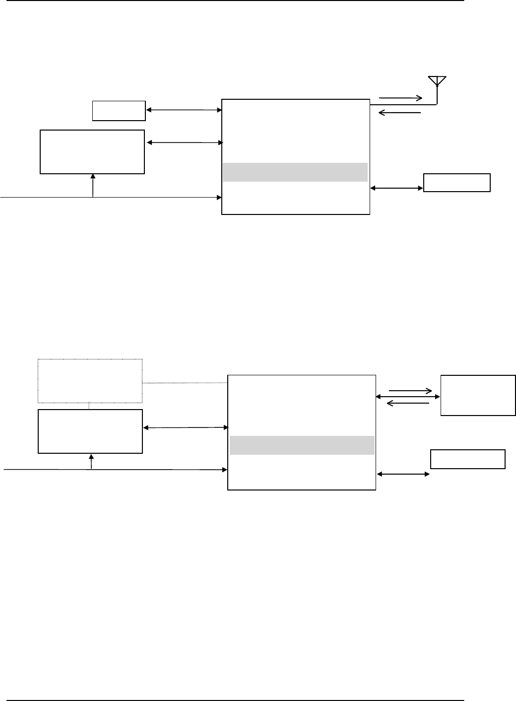
Refer to Figure 2-1 MDR/BDR Interconnect Diagram, for a block diagram of wiring runs and
connector designations. The following paragraphs describe the interconnections directly
related to the mobile data and base station radios.

385700-1006-006 INSTALLATION
Document use is restricted to that described on cover 2-9
The antenna is an electrical conductor.
Contact with power lines may cause
death or serious injury. Do not install
these antennas where there is any
possibility of contact with or high
voltage arc-over from power cables or
service drops to buildings. The
antennas and mast must not be near
power lines during installation, use, or
removal.
Before applying power, verify that the
antenna is securely connected to the MDR
and BDR. Failure to observe these
warnings will damage the equipment.
2.2.1 MOBILE CONFIGURATION INTERCONNECTION
Refer to the mobile configuration diagram in Figure 2-1 MDR/BDR Interconnect Diagram.
Connect the vehicle control equipment to the MDR at the DATA 1 (J2) port on the front panel
of the unit. Connect the appropriate DC power source to the front panel POWER IN (J1) port.
Connect an antenna to ANTENNA (J5) port. The DIAGNOSTIC port (J4) is not connected
during normal operation. It is used for testing purposes. (Refer to paragraph 2.5.2.) . DATA
2 (J3) port may or may not be used in a particular implementation. Its operation is defined in
the ICD.
2.2.2 WAYSIDE CONFIGURATION INTERCONNECTION
Refer to the wayside configuration diagram in Figure 2-1 MDR/BDR Interconnect Diagram.
The BDR rear panel port ANTENNA (J5) connects to the wayside antenna subsystem. The
base station radios connect directly to the wayside control equipment. The BDR rear panel
port DATA 1 (J2) connects to the wayside control equipment. The BDR rear panel port DATA
2 (J3) connects to the redundant set of wayside control equipment. The active control
equipment will provide a differential signal to enable either DATA 1 or DATA 2 port. This
WARNING
WARNING

385700-1006-006 INSTALLATION
Document use is restricted to that described on cover 2-10
signal will be provided via a pair of dry contacts. The BDR provides the source voltage of
nominally +5 VDC and the return path to drive the signals. Refer to BDR Data 1 Port Cable
Pin-outs, for EIA-530 pin assignments. The diagnostic port (J4) is not connected during
normal operation. It is used for testing purposes. (Refer to paragraph 2.5.2.)
2.3 CABLE AND GROUND REQUIREMENTS
The following paragraphs contain the requirements for constructing the interconnect cabling
between the Andrew and vendor supplied equipment.
Construct the MDR power cables, using at least 16-gauge cable. Use the power cable to
ground the MDR.
Use RF coaxial cable to connect the antennas. The cabling must support potential bends in
the path from the mobile antennas to the radios. Loss through this cable must be less than 2
dB.
Construct data and computer signal cabling using 22 AWG shielded cabling. The BDR power
cable is a standard AC power cable using an IEC320 type plug.
All cables shall be shielded for EMI reduction.
385700-1006-006 INSTALLATION
Document use is restricted to that described on cover 2-11
Figure 2-1 MDR/BDR Interconnect Diagram
Vehicle
Control Equipment
J2
DATA 1
J5
ANTENNA
J1
POWER IN
DC Power
MOBILE DATA RADIO
WAYSIDE CONFIGURATION
Wayside
Control Equipment
AC Power
Data
Data
Wayside
Antenna
S
y
stem
2467.84 MHz
2416.64 MHz
2416.64 MHz
2467.84 MHz
J3
DATA 2
Terminal
J4
DIAGNOSTIC
LCP Terminal
J2
DATA 1
J5
ANTENNA
J1
POWER IN
BASE DATA RADIO
J3
DATA 2
J4
DIAGNOSTIC
LCP Terminal
Redundant Wayside
Control Equipment
Data
MOBILE CONFIGURATION

385700-1006-006 INSTALLATION
Document use is restricted to that described on cover 2-12
2.3.1 CONNECTOR PIN-OUTS
Refer to Figures 2-2 through Figure 2-8 for the connector pin-out information for the MDR and
BDR ports. Unlisted pins are no connects or reserved. Refer to attached cable assembly
drawing package for typical external cable details.
Figure 2-2 shows the connector for the MDR front POWER IN connector.
The Power IN connector is a MIL-C_26482, Series 1 connector. The part number is
MS3114E8-3P or equivalent. The mating connector is MS3116F8-3S or equivalent.
Figure 2-2 MDR Input DC Power Pin-outs
CA
B
Pin Assignment Signal
PIN A DC(+)
PIN B Ground
PIN C Ground

385700-1006-006 INSTALLATION
Document use is restricted to that described on cover 2-13
Figure 2-3 shows the connector for the MDR front panel DIAGNOSTIC port.
Note: Other pin assignments correspond to signals used for testing purposes beyond the
scope of this manual.
Figure 2-3 MDR Diagnostic Port LCP Terminal Port Pin-outs
The Diagnostic connector is a MIL-C-26482, Series 1 connector. The part number is
MS3124E18-32S. The mating connector is MS3126F18-32P or equivalent.
Figure 2-4 shows the connector for the MDR front panel DATA 2 port.
Figure 2-4 MDR Data 2 Port Pin-outs
The Data 2 connector is a MIL-C-26482, Series 1 connector. The part number is
MS3124E14-19SY. The mating connector is MS3126F14-19PY or equivalent.
Pin Assignment Signal
PIN A TXD
PIN B RXD
PIN C SIG GND
PIN E ANT0
PIN F ANT1
PIN G ANT2
PIN L SIGA GND
PIN M SIGA GND
PIN N SIGA GND
PIN S RADIO PWR
PIN T RADIO PWR
PIN U RADIO PWR RTN
PIN V RADIO PWR RTN
Pin Assignment Signal
PIN e DIAG_TXD
PIN f DIAG_RXD
PIN g TERM_GND
A
B
C
D
E
FG H
J
K
L
M
N
P
R
ST
UV
Z
JKL
M
N
P
R
S
T
A
C
D
E
F
GH
Y
X
W
VU
B
e
d
c
b
a
jw
gf

385700-1006-006 INSTALLATION
Document use is restricted to that described on cover 2-14
Figure 2-5 shows the connector for the MDR front panel DATA 1 port.
Figure 2-5 MDR Data 1 Port Pin-outs
The Data 1 connector is a MIL-C-26482, Series 1 connector. The part number is
MS3124E14-19S. The mating connector is MS126F14-19P or equivalent.
The Data 1 and Data 2 connectors are uniquely polarized.
Pin Assignment Signal
PIN A TXD(A)
PIN B TXD(B)
PIN C RXD(A)
PIN D RXD(B)
PIN E TXCLK(A)
PIN F TXCLK(B)
PIN G RXCLK(A)
PIN H RXCLK(B)
PIN J RTS(A)
PIN K RTS(B)
PIN L CTS(A) - not used
PIN M CTS(B) – not used
PIN N CD(A)
PIN P CD(B)
PIN R GND
A
B
C
D
E
FG H
J
K
L
M
N
P
R
ST
UV

385700-1006-006 INSTALLATION
Document use is restricted to that described on cover 2-15
Figure 2-6 shows the connector of the BDR rear panel DIAGNOSTIC port. The connector is a
37 pin D-sub. The part number is CINCH 962GE DCU-37S or equivalent. A mating connector
with a metal backshell for shielding purposes should be used.
Note: Other pin assignments correspond to signals used for testing purposes beyond the
scope of this manual.
Figure 2-6 BDR Diagnostic Port Pin-outs
Pin Assignment Signal
PIN 28 DIAG_TXD
PIN 29 DIAG_RXD
PIN 30 TERM_GND
PIN 1
PIN 2
J4
DIAGNOSTIC
PIN 37 PIN 20

385700-1006-006 INSTALLATION
Document use is restricted to that described on cover 2-16
Figure 2-7 shows the connector of the BDR rear panel DATA 1 port (J2). The connector is a
25 pin D-sub. The part number is ITT DBU-25S-FO or equivalent. A mating connector with
a metal backshell for shielding purposes should be used.
Figure 2-7 BDR Data 1 Port Cable Pin-outs
The signals on pins 6, 22, 20 and 23 are provided to enable either DATA 1 or DATA 2 port.
Table 2-1 shows the selection of the BDR data port based on these signals.
Control
Equipment
Inputs
VDC
(Nominal) Control
Equipment
Outputs
VDC
(Nominal) Active
Data Port
CNTL_OUT+
CNTL_OUT- 5
0CNTL_IN+
CNTL_IN- 5
0DATA 2
CNTL_OUT+
CNTL_OUT- 5
0CNTL_IN+
CNTL_IN- 0
5DATA 1
CNTL_OUT+
CNTL_OUT- 5
0CNTL_IN+
CNTL_IN- NC
NC DATA 2
Table 2-1, BDR Data Port Enable Signals
Refer to “ATCS Radio Network Interface Control Document” for complete BDR to wayside
equipment interface information.
Pin Assignment Signal
PIN 1 Shield
PIN 2 TXD(A)
PIN 14 TXD(B)
PIN 3 RXD(A)
PIN 16 RXD(B)
PIN 15 TXCLK(A)
PIN 12 TXCLK(B)
PIN 17 RXCLK(A)
PIN 9 RXCLK(B)
PIN 4 RTS(A) – not used
PIN 19 RTS(B) – not used
PIN 5 CTS(A) – not used
PIN 13 CTS(B) – not used
PIN 7 GND
PIN 6 CNTL_OUT+
PIN 22 CNTL_OUT-
PIN 20 CNTL_IN+
PIN 23 CNTL_IN-
J2
DATA 1
Pin 1 Pin 2
PIN 14

385700-1006-006 INSTALLATION
Document use is restricted to that described on cover 2-17
Figure 2-8 shows the connector of the BDR rear panel DATA 2 port (J3). The connector is a
25 pin D-sub. The part number is ITT DBU-25S-FO or equivalent. A mating connector with a
metal backshell for shielding purposes should be used.
Figure 2-8 BDR Data 2 Port Cable Pin-outs
2.4 COMPONENT JACK LOCATIONS
The following paragraphs describe the purpose and location of the jacks for each of the radio
assemblies.
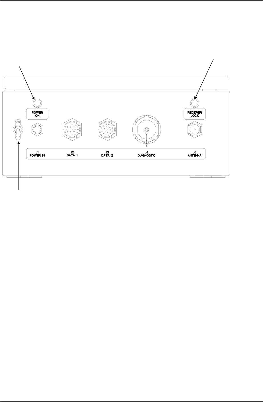
2.4.1 MOBILE DATA RADIO JACK LOCATIONS
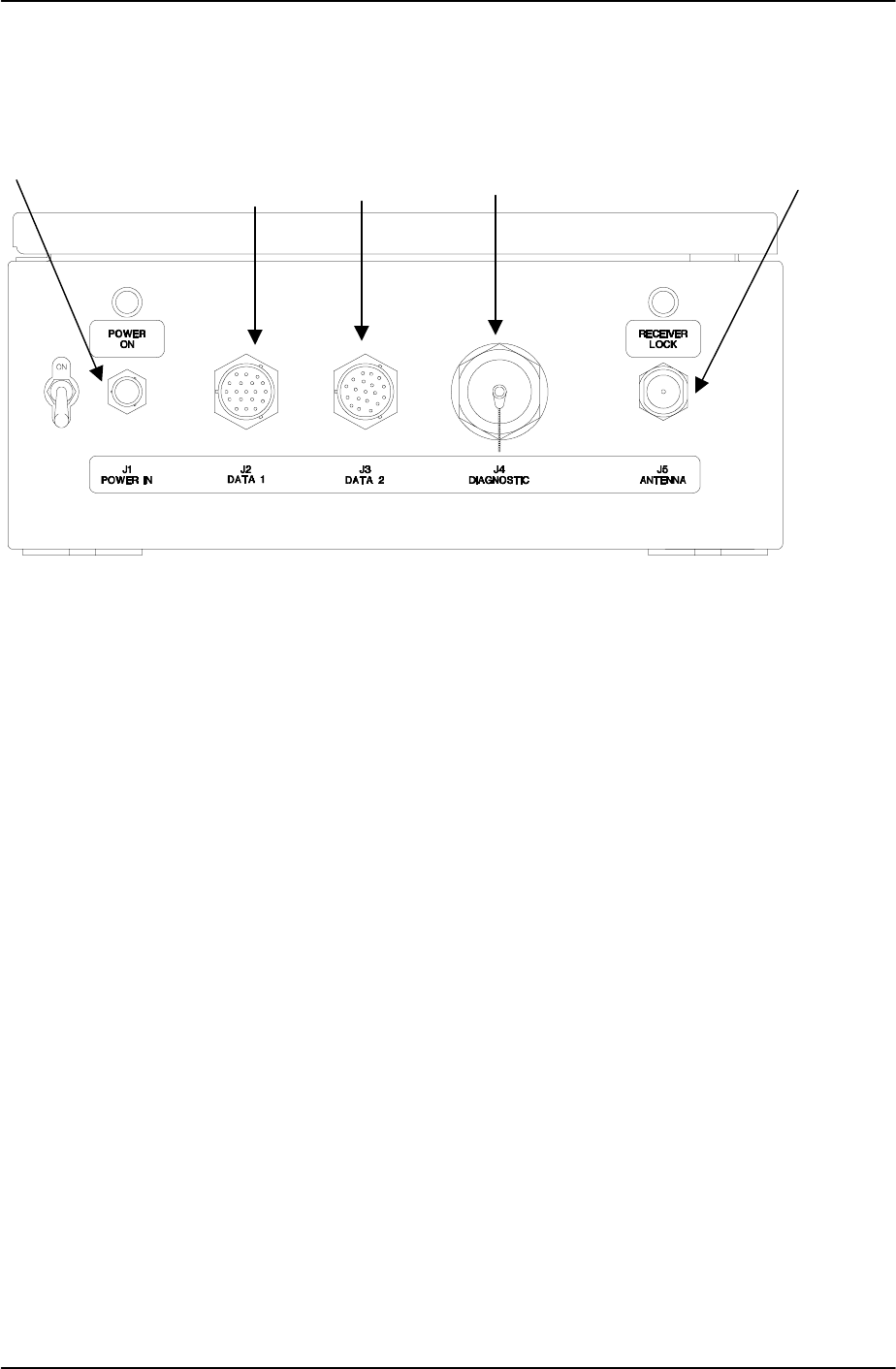
Figure 2-9 depicts the MDR connector panel. The MDR front panel contains two data jacks,
DATA 1 (J2) and DATA 2 (J3). The MDR transmits and receives data from the control
equipment across the DATA 1 port (J2). A cable connects the ANTENNA port (J5) to the
antenna. A cable connects the DIAGNOSTIC port (J4) to an LCP terminal providing a menu-
driven user interface (refer to paragraph 2.5.2). Port POWER IN (J1) connects the MDR to
the VDC power source.
DATA 2 port is an RS-232 port that can be connected to customer provided equipment as
required. DATA 2 provides asynchronous data that is sent from the BDR. The parameters of
this port are programmable via the diagnostic terminal. The DIAGNOSTIC port is
unconnected during normal operation.
Pin Assignment Signal
PIN 2 TXD(A)
PIN 14 TXD(B)
PIN 3 RXD(A)
PIN 16 RXD(B)
PIN 15 TXCLK(A)
PIN 12 TXCLK(B)
PIN 17 RXCLK(A)
PIN 9 RXCLK(B)
PIN 4 RTS(A)
PIN 19 RTS(B)
PIN 5 CTS(A)
PIN 13 CTS(B)
PIN 7 GND
J3
DATA 2
Pin 1 Pin 2
PIN 14
385700-1006-006 INSTALLATION
Document use is restricted to that described on cover 2-18
Figure 2-9 Mobile Data Radio Assembly Jack Locations
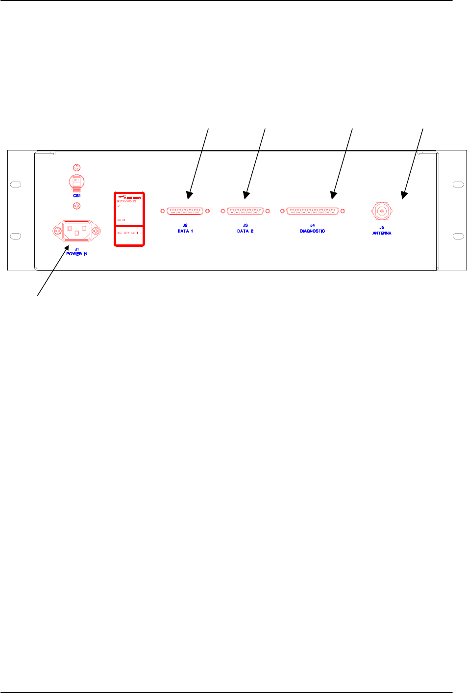
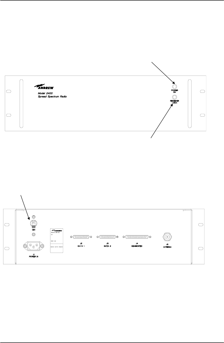
2.4.2 BASE STATION DATA RADIO JACK LOCATIONS
Refer to Base Station Data Radio Assembly Jack Locations. DATA 1 port (J2) connects the
BDR to the wayside control equipment. DATA 2 port (J3) connects the BDR to the redundant
control equipment. Four additional signals, non EIA-530 standard, are used for the selection
of the data port to be used. Refer to paragraph 2.3.1 for connector pin-out information.
DIAGNOSTIC port (J4) is connected to the LCP terminal providing a menu-driven user
interface. Refer to paragraph 2.5.2. ANTENNA port (J5) is the RF port for the antenna.
POWER IN port (J1) receives AC power.
DATA 1
Port
J2
DATA 2
Port
J3
Diagnostic
Port
J4
Antenna
Port
J5
Power
Input
J1
385700-1006-006 INSTALLATION
Document use is restricted to that described on cover 2-19
Figure 2-10 Base Station Data Radio Assembly Jack Locations
Power Input
J1
Diagnostic
Port
J4
DATA 1
Port
J2
DATA 2
Port
J3
Antenna
Port
J5

385700-1006-006 INSTALLATION
Document use is restricted to that described on cover 2-20
2.5 INITIAL PREPARATION FOR USE
Before applying power to the MDR and
BDR, securely connect the RF antennas to
both units. Failure to observe these
cautions can damage the equipment.
The radios are configured at the factory for usage in the field. Default addresses (BDR) and
ID’s (MDR) are installed. The actual addresses and ID’s used in a system must be
programmed by the user. The following procedure explains how this data is programmed into
a radio.
2.5.1 SETTING UP COMMUNICATIONS WITH THE LCP TERMINAL PORT
• Connect the
DIAGNOSTIC ports of each of the radios to a PC running ProComm™ (or
other Terminal Communication Program). Refer to the attached cable drawings for sample
cable information.
• Set the Communication’s program up with the following settings:
Baud Rate = 19200
Parity = None
Data Bits = 8
Stop Bits = 1
Duplex = Full
Terminal Emulation = VT100 or compatible
Transmit Pacing = 0 mSec
Example (if using ProComm™):
• Press ALT-P to bring up the current settings window. This window will allow you to setup
the Baud Rate, Parity, Data Bits, and Stop Bits.
• Press ALT-S to bring up the Setup menu, select Terminal Options. This will allow you to
set Duplex and Terminal Emulation.
• Press ALT-S to bring up the Setup menu, select General Options. This will allow you to
set the Transmit Pacing.
CAUTION

385700-1006-006 INSTALLATION
Document use is restricted to that described on cover 2-21
2.5.2 DIAGNOSTIC/LCP TERMINALS
NOTE: The radio diagnostic port can be connected to either a WYSE™ 100
compatible terminal or a computer simulating such a terminal. The LCP terminal will
denote all future references to the machine connected to the DIAGNOSTIC port.
1. Connect the LCP terminals to each of the radios using the cable assembly from the
DIAGNOSTIC port on the radio to the serial port specified in the LCP terminal
configuration. Refer to attached cable drawings for sample cable information
2. Place power switches to the ON position on each of the radios.
3. Upon completion of the self-test, the LCP terminal will appear as shown below.
**** Starting RCS Self Test... ****
68302 RAM Test: PASSED or FAILED
FLASH TEST: PASSED or FAILED
ATMEL AT59C11 EEPROM Test: PASSED or FAILED
68302 SCC1 Internal Loopback Test: PASSED or FAILED
68302 SCC2 Internal Loopback Test: PASSED or FAILED
68302 SCC3 Internal Loopback Test: PASSED or FAILED
DUART 68681 Local Loopback Test: PASSED or FAILED
**** RCS Self Test Complete ****
Automatically running RCS ... Press 3 <CRs> to abort.
4. Press the <ENTER> key 3 times. This should bring up the RCS Maintenance and
Upgrade menu
Note: The <ENTER> key must be pressed within 3 seconds of seeing the above
message. Failure to do so will require the radio to be power cycled.

385700-1006-006 INSTALLATION
Document use is restricted to that described on cover 2-22
2.5.2.1 RCS MAINTENANCE AND UPGRADE MENU
RCS Maintenance and Upgrade Menu
[0] Download RCS Software
[1] Download Board Level Test Software
[2] Download Flash Download Software
[3] Download Microwave OS-9 Kernel
[4] Download Power-on Self Test
[5] Download Boot
[6] Run Board Level Test
[7] Run RCS
[8] Run RCS, without an SCP
[9] Display Software Version #’s
[10]Reset Radio Enter Option [0 - 10]:
NOTE: If a previous version of the application software has been previously loaded, and
the <ENTER> key was not pressed within 3 seconds, the radio will attempt to
communicate with attached control equipment attached to a DATA port. It will
automatically try to bring up the RCS Application software (option #7). If this
occurs, the operator will have to recycle power to the radio and hit the <ENTER>
key within 3 seconds.
If there isn’t any software loaded for the OS-9 program, the following error
message will be displayed:
UNABLE TO RUN RCS: OS-9 Kernel is not present in Flash.
If this message appears, a terminal error has occurred and the user should contact
Andrew Corporation for additional information.
If there isn’t any software loaded for the RCS application program, the following
error message will be displayed:
UNABLE TO RUN RCS: RCS Application is not present in Flash.
If this message appears, a terminal error has occurred and the user should contact
Andrew Corporation for additional information.

385700-1006-006 INSTALLATION
Document use is restricted to that described on cover 2-23
2.5.3 VEHICLE LCP MENU
The following is a typical command menu that will appear on the computer monitor. The
menu allows the user to manually operate the MDR.
Phase II Vehicle LCP Menu SW Ver #: xxxx
1. Vehicle Address (Train ID) 21. A/D Select
2. Set PN Index (CDMA Code) 22. Set Clock Search
3. Program Synthesizers 23. OS-9 Shell
4. Reserved 24. Set RCS Address
5. Reset DSP 25. Reserved
6. Reserved 26. SSR Status Request
7. Reset PN 27. System Block Status
8. Reset PN (RX, STROBE) 28. Status Request
9. Reserved 29. Show Poll Counters
10. Set Upper Threshold 30. Clear Poll Counters
11. Upper Thres w/o PN Reset 31. RS-232 Parameters
12. Set Lower Threshold 32. Read TRACK/AGC Values
13. Lower Thres w/o PN Reset 33. Set dBm Output Level
14. Set Lower Lock Threshold 34. Change dBm/DAC Values
15. Disable Transmitter 35. Serial EEPROM Display
16. Enable Transmitter 36. Save Current Settings
17. Load SC Register 37. Load Tnd SC Register
18. Disable Test Port 38. Reserved
19. Enable Test Port 39. Reserved
20. PN Test Select 40. Display System Log
Enter Selection
2.5.4 MDR INITIAL OPERATIONAL ADJUSTMENTS
2.5.4.1 UNIQUE ADDRESS QUALIFIER
Perform the following procedures only when first receiving an MDR from the manufacturer.
1. Connect the MDR to the appropriate DC power.
2. Attach a 2 watt or greater, 20 dB power attenuator to the radio’s ANTENNA port.
3. Connect cabling between the radio DIAGNOSTIC port and dumb terminal, an IBM
PC with Procomm™ Software, or any communications software that supports
VT100 emulation.
4. Place the radio power switch to the ON position.

385700-1006-006 INSTALLATION
Document use is restricted to that described on cover 2-24
5. Select #28 (Status Request) from the LCP menu. The Local Command Processor
(LCP) screen appears on the terminal. If the LCP menu does not appear, follow
instruction in Section 2.5.1 to correctly set the terminal.
6. Select #1 (Vehicle Address). Assign an address for that radio. The range of
allowable hexadecimal addresses is from 000116 to FFFE16. Each mobile radio in
the system must have a unique address.
7. After assigning the address for that radio, select #36 (Save Current Settings).
8. Select #35 (Setting) from the LCP menu. Verify the following settings:
• Vehicle ID = “Value set in step 6”
2.5.4.2 THRESHOLD VERIFICATION
1. Select #28 (Status Request) from the LCP menu. The Local Command Processor
(LCP) screen appears on the terminal. If the LCP menu does not appear, follow
instruction in Section 2.5.1 to correctly set the terminal.
• Lower Lock Threshold = factory settings, (thresholds per configuration
sheet shipped with the radio)
• Lower Threshold = factory settings, (thresholds per configuration
sheet shipped with the radio)
• Upper Threshold = factory settings, (thresholds per configuration
sheet shipped with the radio)
2. If the thresholds are different from those on the configuration sheet, contact
Andrew for additional information. These settings are configured at the factory
during production test and should only be modified by qualified personnel.
3. Place the radio power switch to the OFF position unless the following step is to be
completed.
2.5.4.3 MDR DATA 2 PORT CONFIGURATION (OPTIONAL)
The following procedure needs to be completed for those systems in which the Mobile Data
Radio Data 2 port will be utilized.
The DATA 2 port is designed to transmit RS-232 data to a vehicle-mounted instrument. In
order to do this, the DATA 2 port must be configured via the LCP menu prior to operation of
the radio on the vehicle. The allowable RS-232 options are:
Data Rate: 9600 or 19200
Parity: Even, Odd, or None
Data Bits: 7 or 8
Stop Bits: 1 or 2
For example, to set DATA2 for a data rate of 9600, Even parity, 7 data bits, and 2 stop bits
perform the following commands on the LCP menu

385700-1006-006 INSTALLATION
Document use is restricted to that described on cover 2-25
Select the RS-232 Parameters
31↵
Set the Data Rate to 9600:
9↵
Set the Parity to Even:
E↵
Set the Data Bits to 7:
7↵
Set the Stop Bits to 2:
2↵
Upon display of the LCP Menu,
35↵
Read the current RS-232 parameters and verify that the above changes remain.
Place the radio power switch to the OFF position.

385700-1006-006 INSTALLATION
Document use is restricted to that described on cover 2-26
2.5.5 WAYSIDE LCP MENU
The following is a typical command menu that will appear on the computer monitor. The
menu allows the user to manually operate the BDR.
Phase II Wayside LCP Menu SW Ver #: xxxx
1. Send Poll Requests 21. A/D Select
2. Set PN Index (CDMA Code) 22. Set Clock Search
3. Program Synthesizers 23. OS-9 Shell
4. Reset Receiver 24. Set RCS Address
5. Reset DSP 25. Set Frame Count
6. Reserved 26. SSR Status Request
7. Reset PN 27. System Block Status
8. Reset PN (RX, STROBE) 28. Status Request
9. Reserved 29. Show Poll Counters
10. Set Upper Threshold 30. Clear Poll Counters
11. Upper Thres w/o PN Reset 31. Reserved
12. Set Lower Threshold 32. Read TRACK/AGC Values
13. Lower Thres w/o PN Reset 33. Set dBm Output Level
14. Set Lower Lock Threshold 34. Change dBm/DAC Values
15. Disable Transmitter 35. Serial EEPROM Display
16. Enable Transmitter 36. Save Current Settings
17. Load SC Register 37. Load TnD SC Register
18. Disable Test Port 38. Reserved
19. Enable Test Port 39. Reserved
20. PN Test Select 40. Display System Log
Enter Selection
2.5.6 BDR INITIAL OPERATIONAL ADJUSTMENTS
2.5.6.1 UNIQUE RCS ADDRESS QUALIFIER
Perform the following procedures only when first receiving an BDR from the manufacturer.
1. Connect the BDR to the appropriate AC power.
2. Attach a 2 watt or greater, 20 dB power attenuator to the radio’s ANTENNA port.
3. Connect cabling between the radio DIAGNOSTIC port and dumb terminal, an IBM
PC with Procomm™ Software, or any communications software that supports
VT100 emulation.
4. Place the radio power switch to the ON position.

385700-1006-006 INSTALLATION
Document use is restricted to that described on cover 2-27
5. Select #28 (Status Request) from the LCP menu. The Local Command Processor
(LCP) screen appears on the terminal. If the LCP menu does not appear, follow
instructions in Section 1.4.1 to correctly set the terminal.
6. Select #24 (Set RCS Address). Assign an address for that radio. The range of
allowable hexadecimal addresses is from 0116 to FE16. Each base radio in the
system must have a unique address.
7. After assigning the address for that radio, select #36 (Save Current Settings).
8. Select #35 (Setting) from the LCP menu. Verify the following settings:
RCS Address = “Value set in step 6”
2.5.6.2 THRESHOLD VERIFICATION
1. Select #28 (Status Request) from the LCP menu. The Local Command Processor
(LCP) screen appears on the terminal. If the LCP menu does not appear, follow
instruction in Section 2.5.1 to correctly set the terminal.
• Lower Lock Threshold = factory settings, (thresholds per configuration
sheet shipped with the radio)
• Lower Threshold = factory settings, (thresholds per configuration
sheet shipped with the radio)
• Upper Threshold = factory settings, (thresholds per configuration
sheet shipped with the radio)
2. If the thresholds are different from those on the configuration sheet, contact
Andrew for additional information. These settings are configured at the factory
during production test and should only be modified by qualified personnel.
3. Place the radio power switch to the OFF position unless the following step is to be
completed.
2.6 RADIO APPLICATION CODE UPGRADE
The BDR and MDR application codes are field upgradeable. Using the LCP terminal and a
disk supplied by Andrew, the application code can be downloaded into a radio with the
following procedure. The application code diskette (mobile radio = 385700-5002 or base
radio =385700-5003) includes the software version number.
1. Connect the radio to the appropriate input power.
2. Attach a 2 watt or greater, 20 dB power attenuator to the radio’s ANTENNA port.

385700-1006-006 INSTALLATION
Document use is restricted to that described on cover 2-28
3. Connect cabling between the radio DIAGNOSTIC port and dumb terminal, an IBM
PC with Procomm™ Software, or any communications software that supports
VT100 emulation.
4. Place the radio power switch to the ON position.
9. Upon completion of the self-test, the LCP terminal will appear as shown below.
**** Starting RCS Self Test... ****
68302 RAM Test: PASSED or FAILED
FLASH TEST: PASSED or FAILED
ATMEL AT59C11 EEPROM Test: PASSED or FAILED
68302 SCC1 Internal Loopback Test: PASSED or FAILED
68302 SCC2 Internal Loopback Test: PASSED or FAILED
68302 SCC3 Internal Loopback Test: PASSED or FAILED
DUART 68681 Local Loopback Test: PASSED or FAILED
**** RCS Self Test Complete ****
Automatically running RCS ... Press 3 <CRs> to abort.
10. Press the <ENTER> key 3 times. This should bring up the RCS Maintenance and
Upgrade menu
RCS Maintenance and Upgrade Menu
[0] Download RCS Software
[1] Download Board Level Test Software
[2] Download Flash Download Software
[3] Download Microwave OS-9 Kernel
[4] Download Power-on Self Test
[5] Download Boot
[6] Run Board Level Test
[7] Run RCS
[8] Run RCS, without an SCP
[9] Display Software Version #’s
[10]Reset Radio Enter Option [0 - 10]:
11. Select #0 (Download RCS Software). From the terminal computer communications
program select the SEND FILE function with RAW ASCII as the protocol. Select
the drive and directory where the application code diskette is located.
12. After the download is complete, select #9 from the RCS Maintenance and Upgrade
Menu. Verify that the application code version corresponds to the version loaded
in the previous step. Record the software versions on the configuration sheet if

385700-1006-006 INSTALLATION
Document use is restricted to that described on cover 2-29
one is included with the radio.
13. From the RCS Maintenance and Upgrade menu, select option 8 (by pressing ‘8’
and then <ENTER>) to run the RCS application software without an SCP
connected. Verify that the appropriate LCP Menu Screen appears on the LCP
terminal.
14. Place the radio power switch to the OFF position.
2.7 PN SPREADING CODE SELECTION
In order for a BDR to communicate with and MDR, and vice versa, the spreading codes of the
radio must be set to the correct values. The user during system configuration determines the
initial spreading code selected. The spreading code is changed dynamically during operation
based on the user’s system design.
The process to select the spreading code via the LCP menu is given below.
1. Connect the radio to the appropriate input power.
2. Attach a 2 watt or greater, 20 dB power attenuator to the radio’s ANTENNA port.
3. Connect cabling between the radio DIAGNOSTIC port and dumb terminal, an IBM
PC with Procomm™ Software, or any communications software that supports
VT100 emulation.
4. Place the radio power switch to the ON position.
5. Upon completion of the self-test, the LCP terminal will appear as shown below.
**** Starting RCS Self Test... ****
68302 RAM Test: PASSED or FAILED
FLASH TEST: PASSED or FAILED
ATMEL AT59C11 EEPROM Test: PASSED or FAILED
68302 SCC1 Internal Loopback Test: PASSED or FAILED
68302 SCC2 Internal Loopback Test: PASSED or FAILED
68302 SCC3 Internal Loopback Test: PASSED or FAILED
DUART 68681 Local Loopback Test: PASSED or FAILED
**** RCS Self Test Complete ****
Automatically running RCS ... Press 3 <CRs> to abort.
6. Press the <ENTER> key 3 times. This should bring up the RCS Maintenance and
Upgrade menu. Select option 8 (by pressing ‘8’ and then <ENTER>) to run the
RCS application software without an SCP connected. Verify that the appropriate
LCP Menu Screen appears on the LCP terminal.

385700-1006-006 INSTALLATION
Document use is restricted to that described on cover 2-30
RCS Maintenance and Upgrade Menu
[0] Download RCS Software
[1] Download Board Level Test Software
[2] Download Flash Download Software
[3] Download Microwave OS-9 Kernel
[4] Download Power-on Self Test
[5] Download Boot
[6] Run Board Level Test
[7] Run RCS
[8] Run RCS, without an SCP
[9] Display Software Version #’s
[10]Reset Radio Enter Option [0 - 10]:
7. After the LCP menu appears, select #2 to Set PN Code Index. The user will be
prompted to enter T (transmitter) or R (receiver) to choose which code to set.
Choose T (transmitter) and press <ENTER>. The user is then prompted to select
a number that corresponds to the PN spreading code to be selected. The range of
allowable values is listed on the screen as part of the user prompt. This process is
repeated to set the receiver code.
8. Place the radio power switch to the OFF position.
2.8 ANTENNA AND CABLE INSTALLATION
After integrating the MDRs and BDRs into the RCS, ensure that all cabling is securely and
properly attached to each unit. The cable assemblies attached to the individual radio data
ports must be properly shielded. Connect the antenna cable to the radios. Place the MDR
and BDR power switches to the up position (ON). Verify that each unit lights its POWER ON
indicator. Refer to Mobile Data Radio Controls and Indicators, and Base Station Data
Radio Assembly Controls and Indicators.

385700-1006-006 OPERATIONS
Document use is restricted to that described on cover 3-1
CHAPTER 3
OPERATIONS
3.1 CONTROLS AND INDICATORS
The following paragraphs outline the controls and indicators for the MDR and BDR.
3.1.1 MDR CONTROLS AND INDICATORS
Refer to Mobile Data Radio Controls and Indicators. The power switch is on the MDR’s front
panel. With its power switch in the ON position, the front panel POWER ON indicator remains
lit. After the BDR and MDR establish communication, the MDR lights its RECEIVER LOCK
indicator until it loses the RF signal.
3.1.2 BDR CONTROLS AND INDICATORS
Refer to Base Station Data Radio Assembly Controls and Indicators. The BDR has one
control switch, CB1, located on its rear panel. With this switch in the up position, the unit is
ON. With the switch in the ON position, the unit lights its POWER ON indicator. When CB1
is in the down position, the unit is OFF.
Once the BDR has established communication with an MDR, the BDR lights its RECEIVER
LOCK indicator until it loses the RF signal.
Before beginning transmission between
the MDR and BDR, securely connect the
RF antennas to both units. Failure to
observe these cautions can damage the
equipment.
The Base Data Radio and Mobile Data Radios are unlicensed devices
operating under the conditions of FCC part 15 regulations. This
equipment is intended to be installed and operated by professional
parties. It is the responsibility of those parties to insure that the
equipment is operated in compliance with the applicable FCC part 15
specifications.
CAUTION
385700-1006-006 OPERATIONS
Document use is restricted to that described on cover 3-2
Figure 3-1 Mobile Data Radio Controls and Indicators
Power Switch
Power On Indicator
Receiver Lock Indicator
385700-1006-006 OPERATIONS
Document use is restricted to that described on cover 3-3
Figure 3-2 Base Station Data Radio Assembly Controls and Indicators
Power Switch CB1
Receiver Lock Indicator
Power On Indicator

385700-1006-006 OPERATIONS
Document use is restricted to that described on cover 3-4
3.2 STARTUP AND SHUTDOWN PRODECURES
The following procedures ensure that installation does not damage the equipment.
3.2.1 MDR STARTUP
Refer to paragraph 5.3.1, place MDR, for procedures to properly install the MDR. Mount the
MDR on the vehicle with the power switch in the OFF position. Securely connect all cabling
and connect the RF antenna to the front panel ANTENNA port. To start the MDR, perform the
following:
1. Connect the control equipment to the MDR front panel DATA 1.
2. Place MDR power switch to the ON position.
3. Allow up to two minutes for the MDR to warm-up.
3.2.2 BDR STARTUP
Refer to paragraph 5.3.2, place BDR, for procedures to properly install the BDR. To start the
BDR, perform the following:
1. Connect the control equipment to the BDR back panel DATA 1 port.
2. Place CB1 switch on the rear panel of the BDR to the ON position.
3. Allow up to two minutes for the BDR to warm-up before beginning transmission.
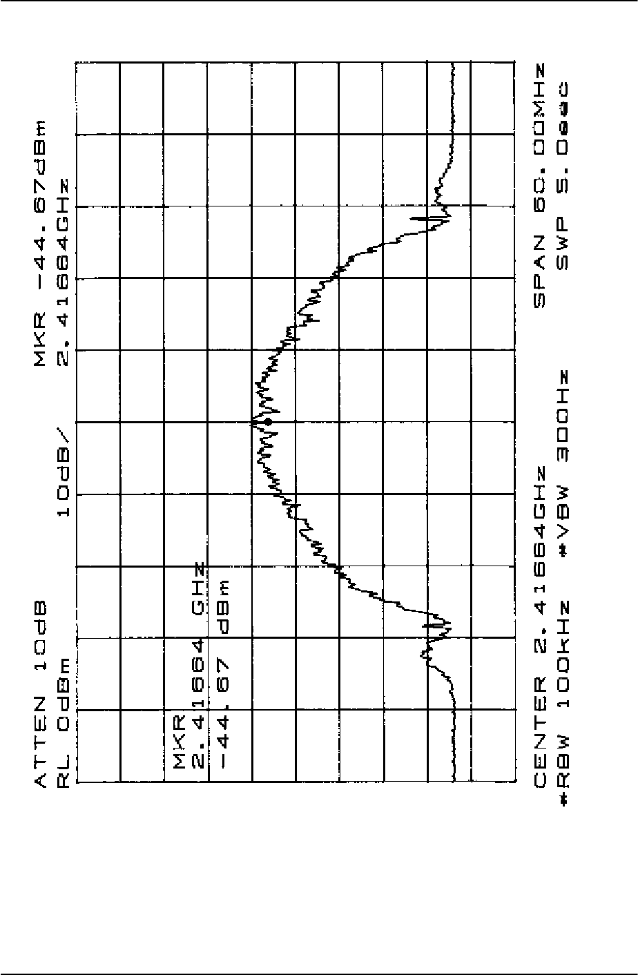
3.2.3 NORMAL OPERATION
Figure 3-4 shows a spectrum analyzer’s possible display (when the MDR is operating normally
with transmitter enabled). Figure 3-3 shows a spectrum analyzer’s possible display when the
BDR is operating normally with the transmitter enabled.
3.2.4 SHUTDOWN
Disconnect all non-RF signals to the MDR and BDR after placing power switches to the OFF
position.
WARNING
IN CASE OF EMERGENCY; Immediately
turn off power to both units.
385700-1006-006 OPERATIONS
Document use is restricted to that described on cover 3-5
Figure 3-3 BDR Output Spectrum

385700-1006-006 OPERATIONS
Document use is restricted to that described on cover 3-6
Figure 3-4 MDR Output Spectrum

385700-1006-006 OPERATIONS
Document use is restricted to that described on cover 3-7
3.3 OUTPUT POWER SETTINGS
The Base Data Radio and Mobile Data Radios are unlicensed devices
operating under the conditions of FCC part 15 regulations. This
equipment is intended to be installed and operated by professional
parties. It is the responsibility of those parties to insure that the
equipment is operated in compliance with the applicable FCC part 15
specifications.
The transmitter output power setting is set at the factory. Additionally, the output level can be
adjusted via computer control of the equipment as defined in the Interface Document. The
actual maximum allowable output level is based on the FCC part 15 Regulations. Table 3-1
lists the maximum allowable output level based on the antenna gain.
Antenna Gain (dBi) Maximum Output Power (dBm)
030
130
230
330
430
530
630
729
828
927
10 26
11 25
12 24
13 23
14 22
15 21
For each additional dB of
antenna gain Reduce the Output power by 1
dB
Table 3-1 – Antenna Gain versus Maximum Output Power
3.4 ANTENNA PLACEMENT
FCC Part 15 Regulation, Section 15.247(b)4, provides for RF safety requirements.
The regulation defines the allowable Maximum Permissible RF Exposure. In order to
meet Maximum Permissible RF Exposure requirements, the user MUST INSURE that
the antenna is located based on the following:
1. When the device will be installed with an external antenna (non leaky feeder
type)the radiator MUST BE located more than 20 cm from the general public.

385700-1006-006 OPERATIONS
Document use is restricted to that described on cover 3-8
2. When the device is installed with leaky feader cable the nominal measured
radiated field at 3 meters is 65.2 dBuV/m which relates to 1 microwatt E.I.R.P.
Although these levels would allow for closer that 20 cm spacing, it is recommended
that the cable be located at a minimum 20 cm separation between the radiator and
the general public.

385700-1006-006 OPERATIONS
Document use is restricted to that described on cover 4-1
CHAPTER 4
PRINCIPLES OF OPERATION
4.1 FUNCTIONAL DESCRIPTION OF EQUIPMENT
4.1.1 MOBILE DATA RADIO AND BASE DATA RADIO
The BDR and MDR are full duplex transceivers that operate as intentional radiators in the
FCC's 2400-2483.5 MHz industrial, scientific, and medical (ISM) band in North America and
within 2400-2500 MHz international band. They operate as unlicensed devices and are
compliant to the applicable FCC part 15 regulations.
The MDR employs both Code Division Multiple Access (CDMA) and Time Division Multiple
Access (TDMA) techniques. CDMA is a function of the Pseudo-random Noise (PN) code
selected for transmission and reception. The particular technique used in Andrew Base and
Mobile Data Radios is Direct Sequence Spread Spectrum (DSSS) technique. In the direct
sequence technique, the information spectrum is spread into a bandwidth many times wider
than the bandwidth of the data alone by using a pseudorandom noise sequence clocked at a
rate significantly greater than the information rate. Each data bit is encoded with a
pseudorandom spreading code. The receiver can recover the original data by using the same
sequence to decode the encoded data bits. Any other selected pseudorandom sequence
simply appears as additional noise at the receiver.
When power is applied to a radio, the radio configures the transmit and receiver spreading
sequences from data stored in the radio’s nonvolatile memory. After the radio configuration is
completed, the Control Equipment can change the spreading sequences. The base station
radios and mobile data radios maintain a pool of available PN codes or channels. Each radio
requires a code. The transmit and receive codes are different. The receive code of the MDR
or BDR must equal the other unit’s transmit code. Adjacent BDRs should not have the same
codes.
In normal operation, all MDR’s in the same control zone operate with the same set of transmit
and receive spreading codes. Time Division Multiple Access techniques are used to minimize
interference between the MDR’s.
Normally, the BDR keeps its transmitter on all the time. The MDR on the vehicle turns on its
transmitters in response to being specifically polled by a BDR. The BDR commands the MDR
to bring up its transmitter and send any pending poll responses from the vehicle control
equipment. The MDR turns off its transmitter if it fails to get confirmation in a certain period of
time that the BDR has “locked” to the MDR. Also, MDR will turn off its transmitter after the
BDR successfully “locks” to the MDR transmitter and the MDR sends its response to the BDR.
385700-1006-006 OPERATIONS
Document use is restricted to that described on cover 4-2
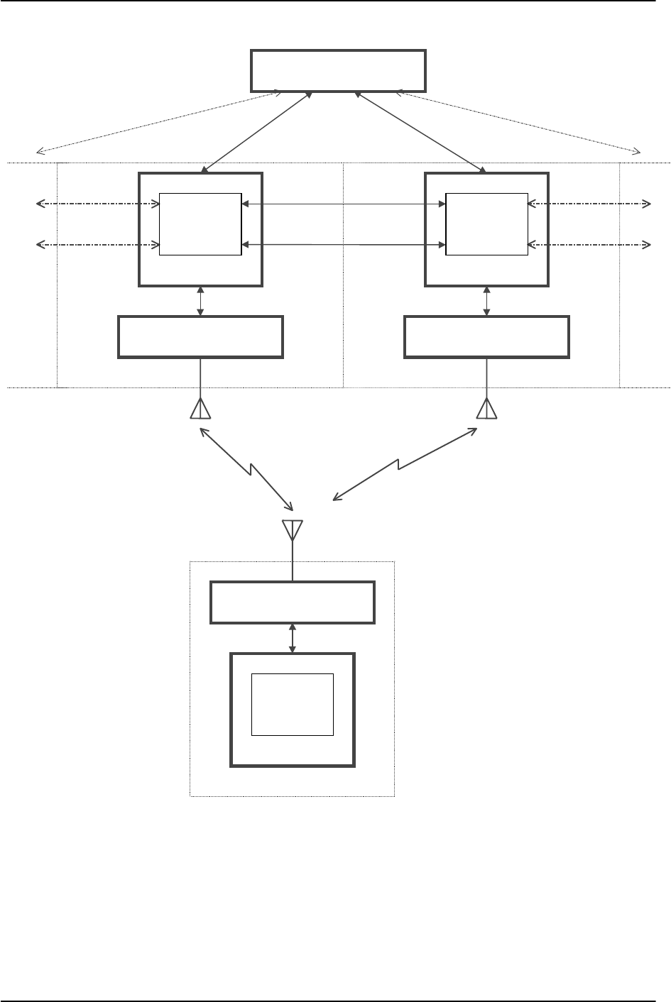
4.1.2 RADIO NETWORK ARCHITECTURE
The typical communication flow consists of wayside equipment (user control equipment and
BDRs) communicating with mobile equipment (user control equipment and MDRs). Wayside
to mobile communication can be distributed over a single or a number of radio networks. Each
control region is considered as a single radio network. The regional control equipment uses a
simple roll-call polling technique to communicate with all the vehicles in the region during a
communication cycle. When a train approaches a region boundary it is handed over to the
next region's radio network by using a software hand-off algorithm.
4.1.2.1 RF TRANSMISSIONS
Full duplex operation is achieved by utilizing separate frequency ranges within the 2400 -
2483.5 MHz band for each direction of communications. Data is transmitted from base radio to
mobile using one range and from mobile to base radio over another frequency range. Refer
to Table 1-2 Mobile Data Radio Assembly Specifications and Table 1-3 Base Station Radio
Assembly Specifications.
4.1.2.2 BASEBAND DATA RATE
The radio network operates at a synchronous baud rate of 64Kbps.
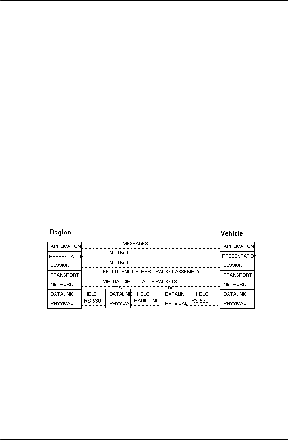
4.1.2.3 OSI LAYERS
The radio network is developed following the ISO (International Standard Organization) Open
Systems Interconnection (OSI) Reference Model. The radio network is modular in design.
Industry standard protocol, interfaces and hardware are used to easily interface third party
equipment.
Figure 4-1 Radio Network OSI Layers
385700-1006-006 OPERATIONS
Document use is restricted to that described on cover 4-3
Figure 4-2 Radio Network Architecture
Mobile Data Radio
Vehicle
Central Control
Base Data Radio
Re
g
ion
Base Data Radio
Re
g
ion
Central
Network
Re
g
ion-to-Vehicle RF
Wayside
Control
Equipment
Wayside
Control
Equipment
Vehicle
Control
E
q
ui
p
ment

385700-1006-006 OPERATIONS
Document use is restricted to that described on cover 4-4
4.1.2.3.1 PHYSICAL LAYER
The physical layer is composed of a synchronous serial interface between the control
equipment and the base or mobile transceiver and a radio to radio link based on spread
spectrum technology. The baseband interfaces are based on the EIA-530 interface. The RF
radio link is based on Direct Sequence Spread Spectrum modulation.
4.1.2.3.2 DATALINK LAYER
The data link layer is based on the HDLC (High-level Data Link Control) protocol to
communicate over the radio channel between the base Radio Communication System (RCS)
and mobile RCS. The same protocol is also used to communicate between the RCS and the
control equipment over the EIA-530 interface. A sliding window of one is implemented for the
transfer of HDLC Information Frames (I frames).
The HDLC Information frame (I frame) format is used to transfer data between the base radio
and mobile radio as well as between the radio system and control equipment. The length of a
frame is programmable. Currently is set to 81 bytes (including the two flag bytes). The
wayside control equipment sends an ATC frame to the radio system along with proper RCS
address, control byte and CRC. The first two bytes of the ATC frame will contain the address
of the vehicle. This vehicle address will be used by the radio system to address a mobile radio
on a vehicle. The control byte determines the type of frame. The radio communication system
adds the CRC and flags to the ATC frame and transmits the packet over radio channel.
Figure 4-3 SCP to RCS Frame Format
A mobile radio is addressed by its two byte Address. Two addresses are reserved. A train
address of zero hexadecimal ‘0000’ is not a legal value. The train address hexadecimal ‘FFFF’
is reserved for a broadcast message to all the trains in a region. A broadcast message will
automatically be retransmitted by the BDR until the regional control equipment clears the
frame. A vehicle will send no response to the broadcast message.
Flag RCS
Address Control
Byte
Communications-Control System Frame
Maximum 75 bytes
Cyclic
Redundancy
Check Flag
Train ID Car ID Region ID Control
Byte Communications-Control System Data
Maximum 73 B
y
tes
ATC Equipment to Andrew Radio Frame Format
Communications-Control System Frame Format

385700-1006-006 OPERATIONS
Document use is restricted to that described on cover 4-5
The radio communication system at the receiving end receives the packet and passes it to the
vehicle control equipment. The successful receipt of an I frame must be acknowledged by the
receiving RCS and control equipment. This is done by incrementing the Nr field of the control
byte within the next frame sent.
If a vehicle has more than one radio communications system, one of them acts as the main
unit and the others act as auxiliary radios. An MDR responds to a poll only if it is pre-loaded
with a response message by the vehicle control equipment. For vehicles with more than one
MDR, the vehicle control equipment must direct which MDR will be pre-loaded with a
response. Hence, all radio systems in a train receive the message from the region control
equipment but only the main radio system sends the response back.
Additional information about the message protocol can be found in the referenced ICD
document.
4.1.3 MDR/BDR COMMUNICATIONS HANDLING
A communications cycle is the exchange of information between the wayside control
equipment and each vehicle control equipment within the region. During a typical
communications cycle, each vehicle control equipment will be sent a poll request, which will be
acknowledged by a poll response from the vehicle control equipment. Each communications
cycle is followed by the specific command that clears untransmitted messages before
proceeding. The wayside control equipment must query the base data radio every 10 to 20
ms for a poll response, and all poll requests must be sent to the base radio at the beginning of
the communications cycle (within the constraints of the protocol). Mobile radios are polled in
sequence one after the other in a round robin fashion.
The data exchange is based on the High-Level Data Link Control (HDLC) standard protocol to
communicate over the radio channel between the Andrew base and mobile radios. The same
protocol is also used to communicate between base radio and wayside control equipment and
between mobile radio and mobile control equipment over the EIA-530 interface. The
handshaking sequence required by the communications protocol precedes each poll
response.
The referenced Interface Control Document establishes the protocols and interfaces between
wayside and vehicle Control Equipment and Mobile and Base Data Radios.
4.1.4 PN SPREADING CODES
The Direct Sequence Spread Spectrum and CDMA operation of the radios are controlled by
the Pseudo Noise spreading codes contained within the non volatile memory of the radios.
Normal operation of the radios requires (1) that the BDR transmit spreading code equal the
MDR receive spreading code, (2) that that the MDR transmit spreading code equal the BDR
receive spreading code, and (3) that the transmit and receive spreading codes within any
radio be different. The radios are configured with over 80 different spreading codes.
Selection of the codes by the user-supplied equipment is covered in the Radio Communication
System Interface Control Document. Selection of the codes from the LCP terminal is covered
in Chapter 8.

385700-1006-006 OPERATIONS
Document use is restricted to that described on cover 4-6
4.1.5 ANTENNA SWITCHING CONTROLS
The MDR Data 2 Port includes 3 signals, see MDR Data 2 Port Pin-outs, that can provide 20
ma of drive current. The current based signals, ANT0-ANT2, can be connected to a user
supplied external switch that controls a multiple antenna configuration that is connected to the
MDR. The return current path signals, SIGA GND, are tied together inside the radio. The
software control of the antenna select lines is defined in the Radio Communication System
Interface Control Document.
The MDR Data 2 Port also provides a power and power return path, see MDR Data 2 Port
Pin-outs, to the user. The power signal, RADIO PWR, is taken directly from the user supplied
input source. The electrical path is made with 22-gauge wire. The user is responsible to
insure that (1) the current draw is within the limits that this gauge wire can support and (2) that
the user supplied DC power source can supply this current load as well as the current load
required by the MDR.

385700-1006-006 MAINTENANCE AND TROUBLESHOOTING
Document use is restricted to that described on cover 5-1
CHAPTER 5
MAINTENANCE AND TROUBLESHOOTING
5.1 PREVENTIVE MAINTENANCE, INSPECTION, AND CLEANING
This section describes preventive maintenance procedures for the MDR and BDR assemblies.
Inspect and clean the MDR and BDR assemblies yearly or as required in severe environments
to ensure continued operation. After inspecting the assemblies, take any necessary remedial
actions. See Table 5-1 for assistance.
Table 5-1 Preventive Maintenance Inspection and Cleaning
Description Normal Condition Remedial Action
1. Inspect each unit for
missing or loose
hardware
All hardware in place and
secure. Replace missing hardware or
tighten as necessary.
2. Inspect each unit for dust
and dirt accumulation. The units should remain free
of dust or dirt accumulation. Clean with a damp cloth.
3. Inspect all wiring and
cabling. No cracking, splitting,
breakage, or pinching of
insulation or connectors. No
signs of aging.
Replace bad wiring or cabling
as soon as possible.
Note: Power the equipment off during external cleaning.
5.2 TROUBLESHOOTING
Before beginning any in-depth troubleshooting, ensure that power is available to the unit.
Ensure that all cable connections are secure. Refer to Figure 5-1 and Figure 5-2 for MDR and
BDR initial troubleshooting.
This section describes the troubleshooting procedures for the MDR and BDR assemblies.
Locate the unit’s symptom in the Fault Indication column. The Fault Description column lists
components or functions that can cause faults. The last column, Corrective Action, specifies
the action necessary to correct the fault. After taking corrective action, perform the
appropriate diagnostic procedure to verify that the correction was successful.
For malfunctions that the fault isolation table does not list, contact Andrew’s technical support
personnel.
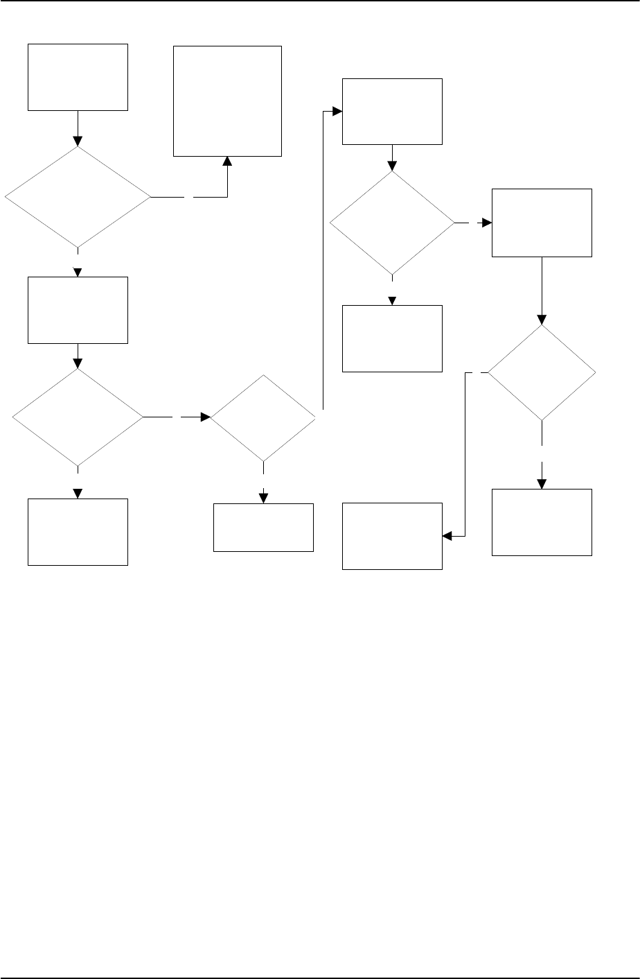
385700-1006-006 MAINTENANCE AND TROUBLESHOOTING
Document use is restricted to that described on cover 5-2
Observe
Power on
Indicator
Is Power on
Indicator
Illuminated?
Check Input
Power Cabling
Is Cabling
Properly
Connected?
Properly
Connect
Cabling
Continue MDR
Troubleshooting
Process
Is Cabling
Damaged?
Replace
Cabling
Check Power
Switch
Is Power
Switch in On
Position?
Place Power
Switch to On
Position
Check Input 28
VDC Connector
for nominal 28
VDC
Is 28 VDC
Present?
Check
External
Power Supply
Replace MDR
N
N
N
N
Y
Y
Y
Y
N
Y
Figure 5-1 MDR Fault Isolation Flow Diagram
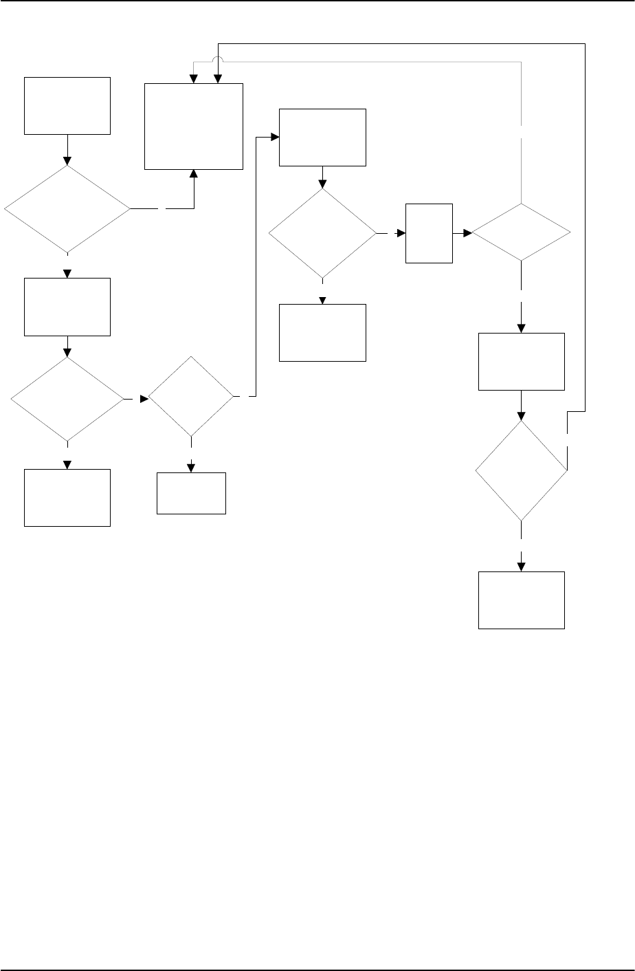
385700-1006-006 MAINTENANCE AND TROUBLESHOOTING
Document use is restricted to that described on cover 5-3
Observe
Power ON
Indicator
Is Power ON
Indicator
Illuminated?
Check Input
Power Cabling
Is Cabling
Properly
Connected?
Properly
Connect
Cabling
Continue BDR
Troubleshooting
Process
Is Cabling
Damaged?
Replace
Cabling
Check CB1
Power Switch
Is CB1 in ON
Position?
Place CB1 to
On Position
Check
Unit
Fan
N
N
N
N
Is Unit Fan
Operating?
Check
External
Power Feed
Replace BDR
N
Y
Y
Y
Y
Y
Is External
Power Feed
Good?
N
Y
Figure 5-2 BDR Fault Isolation Flow Diagram

385700-1006-006 MAINTENANCE AND TROUBLESHOOTING
Document use is restricted to that described on cover 5-4
NOTE
The following table only isolates faults to
the LRU level. The test procedures in
Section III of this chapter provide
assistance for further fault isolation. If an
LRU fails, return it to the equipment
manufacturer for maintenance or repair.
Step Fault Indication Fault Description Corrective Action
1 MDR front panel
POWER ON
indicator not lit
when power is on.
Possible loose power
cable connection,
faulty power cable,
power switch in OFF
position, faulty power
supply, or faulty power
indicator.
Ensure that the power cable is properly
and securely connected to the radio and
power supply. After the cable is properly
and securely connected, place the power
switch in the ON position. Refer to
section 5.4.1,
If the appropriate DC voltage is not
present, the fault is elsewhere. Refer to
the appropriate documentation for
vendor equipment. Refer to section
5.3.1, place MDR.
2 BDR front panel
POWER ON
indicator not lit
when power is on.
Possible loose cable
connection, faulty
power cable power
switch in OFF position,
faulty power supply, or
faulty power indicator.
Ensure that the power cable is properly
and securely connected to the radio and
power supply. After the cable is properly
and securely connected, place CB1 in
the ON position and listen for the unit
fan. If the fan is not functioning, remove
and replace the radio. Refer to section
5.3.2, place BDR. Return the radio to the
equipment manufacturer. Refer to
section 2.1.2 for equipment returns.
Refer to the appropriate documentation
for vendor equipment.
NOTE: The unit voltage range for the corrective action procedure is the full input supply
range of the unit.
Table 5-2 Radio Assembly Fault Isolation

385700-1006-006 MAINTENANCE AND TROUBLESHOOTING
Document use is restricted to that described on cover 5-5
5.3 CORRECTIVE MAINTENANCE
This section describes the removal and replacement of the MDR and BDR assemblies. See
Section Radio Assembly Fault Isolation, to determine when to remove and replace a line
replaceable unit (LRU).
5.3.1 REMOVE AND REPLACE MDR
Referring to Figure 5-3, perform the following actions to remove the MDR (shown as Item 2)
1. Place MDR (2) power switch (3) to the OFF position.
2. Disconnect the control equipment data cable that attaches to the MDR’s DATA
1 port (5), DATA 2 port (7), and DIAGNOSTIC port (8) if installed.
3. Disconnect the DC power cable from POWER IN (4), the antenna feed line
from ANTENNA port (6).
4. Remove four bolts (1) from the MDR (2) mounting brackets.
5. Remove mobile data radio (2).
Referring to Figure 5-3, perform the following actions to replace the MDR:
1. Place MDR (2) in position.
2. Secure MDR (2) with four bolts (1).
3. Reconnect the antenna feed line to port (6).
4. Reconnect the control equipment data cable to attach the MDR (2).
5. Reconnect the DC power cable to the POWER IN (4). Place MDR (2) power
switch (3) to ON position.
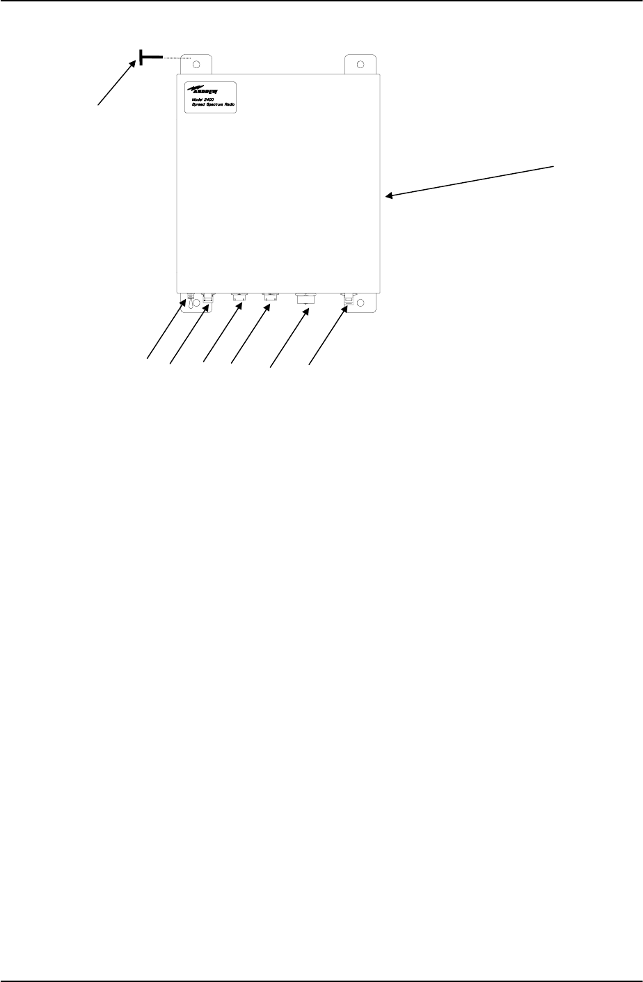
385700-1006-006 MAINTENANCE AND TROUBLESHOOTING
Document use is restricted to that described on cover 5-6
Figure 5-3 Remove and Replace MDR
5.3.2 REMOVE AND REPLACE BDR
Referring to Figure 5-4, perform the following actions to remove the BDR from the 19” rack
(shown as item 2):
1. Place CB1 (3) to the OFF position.
2. Disconnect the AC power cable from J1 (5), the wayside BTC Control
Equipment cabling from DATA 1 port (4) or DATA 2 port (7), the antenna feed
line from ANTENNA port (5). Remove cable attached to DIAGNOSTIC port (8),
if installed.
3. Remove and retain four rack-mounting screws (1) from the BDR (2).
4. Remove the BDR (2) from the equipment rack.
1
2
3456
7
8
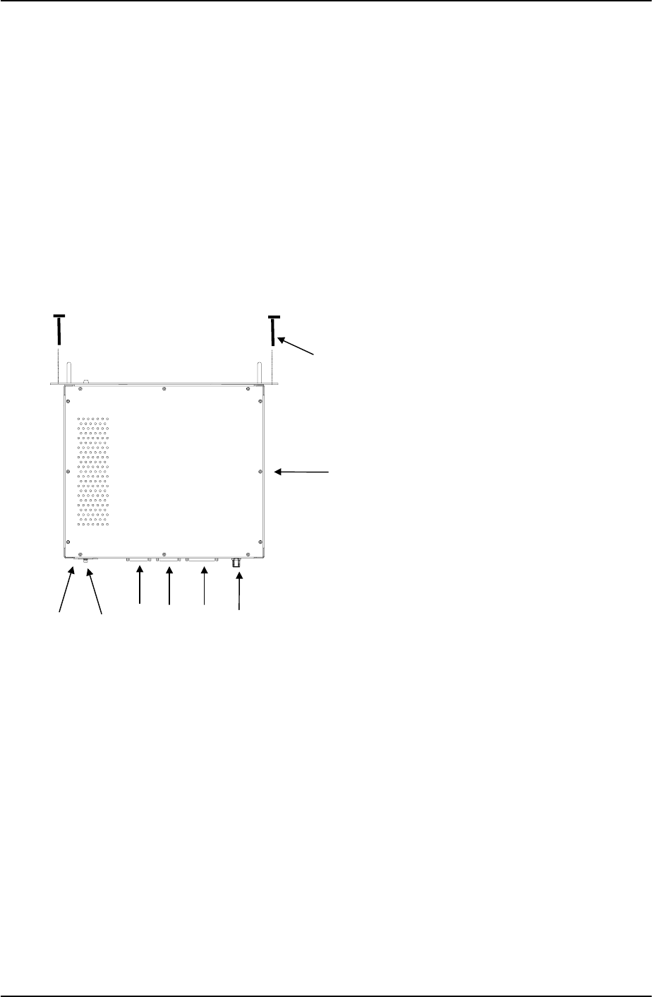
385700-1006-006 MAINTENANCE AND TROUBLESHOOTING
Document use is restricted to that described on cover 5-7
Referring to Figure 5-4, perform the following actions to replace the BDR:
1. Place the BDR (2) in the equipment rack.
2. Secure the BDR (2) to the equipment rack with four rack-mounting screws (1).
3. Reconnect the Control Equipment cable to DATA 1 port (4), and the antenna
feed line to ANTENNA port (5). Reconnect cables to other ports, if any.
4. Reconnect the AC power cable to POWER IN port (5). Place CB1 (3) to the
ON position.
Actions to remove or replace the pole-mounted BDR are the same as described for the MDR
in paragraph 5.3.1.
Figure 5-4 Remove and Replace BDR
1
2
3546
78

385700-1006-006 MAINTENANCE AND TROUBLESHOOTING
Document use is restricted to that described on cover 5-8
5.4 TEST PROCEDURES
Refer to Table 5-3 for a list of test equipment to perform the following test procedures. If
necessary, substitute an equivalent to the equipment listed.
The following test procedures help the user verify that a radio is faulty. Return faulty radios to
Andrew Corporation for maintenance and repair. Refer to paragraph 2.1.1 for equipment
return information.
Equipment Qty Part Number
Computer Terminal 1 IBM PC w/Procomm Software
Diagnostic Cable (Mobile) 1 385700-1811
Diagnostic Cable (Base) 1 385700-3811
Power Attenuator w/N Connector 1 Inmet 12N10W-20 dB
Spectrum Analyzer 1 HP8595A
RF Test Cable, w/N Connector 2 RG214
Attenuator 20 dB A/R Inmet 6N-20
Oscilloscope 1 Tektronics 2465 or equivalent
General Purpose Meter (DVM) 1 Fluke 77 or equivalent
Table 5-3 Test Equipment
5.4.1 MDR POWER VERIFICATION
1. Attach a 2 watt or greater, 20 dB power attenuator to the radio’s ANTENNA
port.
2. Using a power supply with a current and voltage meter, power up the radio with
24 VDC.
3. Place unit’s power switch to the ON position.
4. For 24 VDC input, nominal current is 1.0 amps with the transmitter
off. When the transmitter is on nominal current consumption is
1.6 amps.
5.4.2 BDR POWER VERIFICATION
1. Place CB1 to the ON position.
2. Ensure that the BDR lights its front panel POWER ON indicator.
3. Verify that the fan is on by listening to the sound.
NOTE
If the PC is properly connected to the radio
DIAGNOSTIC PORT, the LCP menu
automatically appears on the screen after the
radio is ON and the radio self-test is completed.
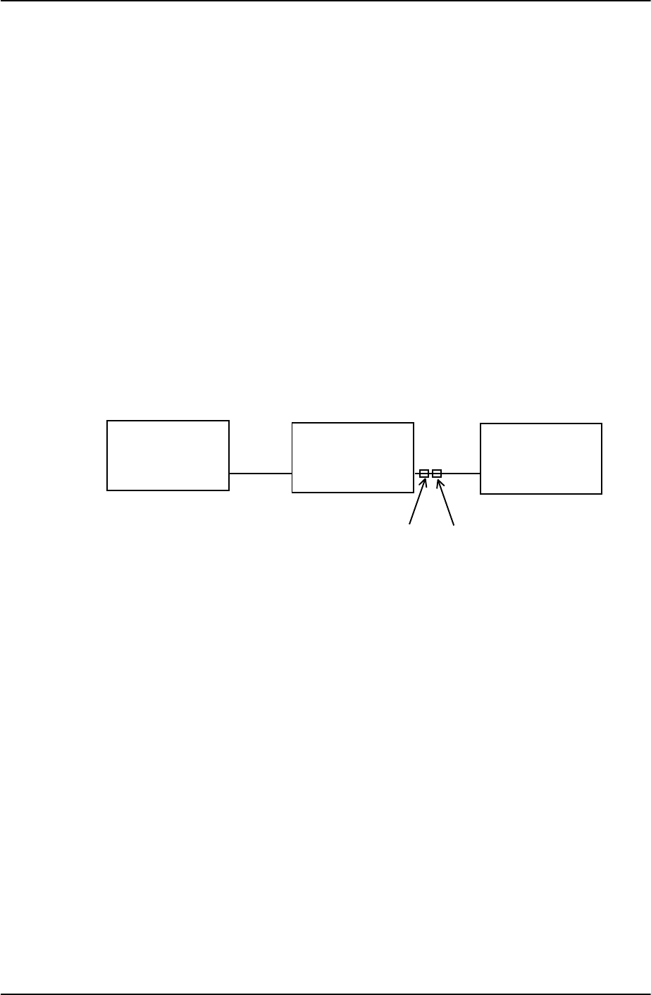
385700-1006-006 MAINTENANCE AND TROUBLESHOOTING
Document use is restricted to that described on cover 5-9
5.5 MDR TESTS
The following sections provide procedures to test the MDR.
5.5.1 MDR TRANSMITTER TEST SETUP
Referring to MDR Transmitter Fault Isolation Test Setup, perform the following actions to
prepare for the MDR transmitter test:
1. Connect the power cable to the MDR at the POWER IN port.
2. Connect a PC to the MDR with a diagnostic cable at the DIAGNOSTIC port.
3. Connect a 20 dB power attenuator to the MDR at the ANTENNA port.
4. Connect a 20 dB power attenuator to the spectrum analyzer RF port.
5. Connect a N cable from the ANTENNA port attenuator to the attenuator at the
INPUT of the spectrum analyzer.
Figure 5-5 MDR Transmitter Fault Isolation Test Setup
PC MDR
Diagnostic
J4 Antenna
J5
Spectrum
Analyzer
Input
20 dB
Power
Attenuator
20 dB
Attenuator

385700-1006-006 MAINTENANCE AND TROUBLESHOOTING
Document use is restricted to that described on cover 5-10
For this test, set up the spectrum analyzer as follows:
• Center Frequency = 2467.84 MHz
• Span = 60 MHz
• Resolution Bandwidth = 100 KHz
• Video Bandwidth = 300 Hz
• Atten = 10 dB
• Ref = 0 dBm
• SWP = Auto
• Marker = 2467.84 MHz
5.5.2 MDR TRANSMITTER FAULT ISOLATION TEST
After preparing for the test, perform the following to isolate the transmitter fault:
1. Place the MDR power switch to the ON position.
2. Bring up the Diagnostic LCP screen. Refer to section 2.5.2 for details. Verify
that the radio self test is completed successfully.
3. At the PC’s LCP menu, select command #16 (Enable Transmitter).
4. Select command #33 (Set dBm output level.) Set output level to 24 dBm.
5. Use the spectrum analyzer’s peak search function to monitor the output power.
6. Compare the output spectrum peak level to MDR Output Spectrum. The level
should be within ±3 dB of the level shown in Error! Reference source not
found..
7. At the LCP menu, select command #15 (Disable Transmitter). The signal
should be down a minimum of 40 dB from the enable levels.
5.5.3 MDR ONLY RECEIVER FAULT ISOLATION TEST SETUP
Refer to MDR Receiver Fault Isolation Test Setup. Preparation for the test to isolate the
MDR receiver fault is similar to the transmitter test setup. The 20 dB attenuation may remain
on the ANTENNA port for the remainder of this test. Referring to MDR Receiver Fault
Isolation Test Setup, perform the following actions:
1. Connect the power cable to the MDR at INPUT 28 VDC.
2. Connect the PC to the MDR with a diagnostic cable at the DIAGNOSTIC port.

385700-1006-006 MAINTENANCE AND TROUBLESHOOTING
Document use is restricted to that described on cover 5-11
Figure 5-6 MDR Receiver Fault Isolation Test Setup
5.5.4 MDR ONLY RECEIVER FAULT ISOLATION TEST
After preparing for the test, perform the following steps to isolate the receiver fault:
8. Place MDR power switch to the ON position.
9. Bring up the Diagnostic LCP screen. Refer to section 2.5.2 for details. Verify
that the radio self test is completed successfully.
10. After the LCP menu appears, select command #12 (Set Lower Threshold). Set
the lower threshold to 01.
11. Select command #14 (Set Lower Lock Threshold). Set upper threshold to 01.
12. Select command #10 (Set Upper Threshold). Set lower lock threshold to 02.
13. If the MDR does not light the RECEIVER LOCK indicator, replace the MDR.
14. Select command #10 (Set Upper Threshold). Set the lower threshold to FF.
15. Select command #12 (Set Lower Threshold). Set upper threshold to FE.
16. Select command #14 (Set Lower Lock Threshold). Set lower lock threshold to FE.
17. If the MDR RECEIVER LOCK indicator is still on, replace the MDR.
18. Place MDR power switch to the OFF position.
5.5.5 MDR/BDR RECEIVER TEST SETUP
Referring to Figure 5-7, perform the following to prepare for the MDR receiver test setup:
Note: This test requires the use of a fully functional BDR.
1. Place MDR and BDR power switches to the OFF position.
2. Place 20 dB power attenuator on the BDR ANTENNA port. Place an additional
20 dB of attenuation to the power attenuator attached to the BDR. Connect a
20 dB power attenuator to the MDR at the ANTENNA port. Place an additional
20 dB of attenuation to the power attenuator attached to the MDR.
3. Connect a N cable from the BDR attenuator to the MDR attenuator.
4. Connect a PC to each radio with diagnostic cables at the DIAGNOSTIC ports.
5. Connect power to the units. Place MDR and BDR power switches to the ON
positions, and bring up the Diagnostic LCP screens. Refer to section 2.5.2 for
details. Verify that the radio self test is completed successfully.
PC MDR
Diagnostic
J4 Antenna
J5
20 dB
Power
Attenuator

385700-1006-006 MAINTENANCE AND TROUBLESHOOTING
Document use is restricted to that described on cover 5-12
6. After the BDR LCP menu appears, select command #28 (Status Request).
Record the Transmit and Receive PN Code Indices.
7. On the MDR LCP menu, set the Transmit PN code index equal to the BDR
Receive PN code index recorded above. The code is set as follows from the
MDR LCP menu:
2 ↵
T ↵
xx ↵ where xx is the BDR Receive PN code index
On the MDR LCP menu, set the Receive PN code index equal to the BDR
Transmit PN code index recorded above. The code is set as follows from the
MDR LCP menu:
2 ↵
R ↵
xx ↵ where xx is the BDR Transmit PN code index.
8. On the MDR LCP menu, select command #28 (Status Request). Verify that the
Upper, Lower, and Lower Lock Thresholds are the same as written on the
configuration sheet shipped with the radio.
9. On both the MDR and BDR LCP terminals, select command #33 (Set dBm
output level.) Set each radio transmitter output level to 24 dBm.
10. At the BDR LCP menu, select command #16 (Enable Transmitter).
11. Verify that the MDR RECEIVER LOCK light is on. If it fails to illuminate, the
MDR is not operational.
12. If the
RECEIVER LOCK light is illuminated, either the MDR was not configured
correctly (i.e. PN code indices) prior to this test, the antenna connection was
faulty or the factory should be contacted for further information.
13. From the respective LCP terminals, shut off the radio transmitters by selecting
command #15 (Disable Transmitter).
14. Place the MDR and BDR power switches to the OFF position.
Figure 5-7 MDR Receiver Test Setup
PC BDR
Diagnostic
J4 Antenna
J5
20 dB Power
Attenuator
20 dB
Attenuator
MDR
Antenna
J5 Diagnostic
J4
PC

385700-1006-006 MAINTENANCE AND TROUBLESHOOTING
Document use is restricted to that described on cover 5-13
5.6 BDR TESTS
The following sections provide test setup information for the BDR.
5.6.1 BDR TRANSMITTER SETUP
Referring to Figure 5-8, perform the following to prepare for the BDR transmitter fault isolation
test:
1. Connect power cable to BDR.
2. Connect the PC to the BDR with a diagnostic cable at the DIAGNOSTIC port.
3. Connect a 20 dB power attenuator to the BDR at the ANTENNA port.
4. Connect a 20 dB power attenuator to the spectrum analyzer RF port.
5. Connect a N cable from the ANTENNA port attenuator to the attenuator at the
INPUT of the spectrum analyzer.
Figure 5-8 BDR Transmitter Fault Isolation Test Setup
For the BDR transmitter fault isolation test, set-up the spectrum analyzer as follows:
Center Frequency = 2416.64 MHz
Span = 60 MHz
Resolution Bandwidth= 100 KHz
Video Bandwidth = 300 Hz
Attn = 10 dB
Ref = 0 dBm
SWP = Auto
Marker = 2416.64 MHz
5.6.2 BDR TRANSMITTER FAULT ISOLATION TEST
After preparing for the test, perform the following steps to isolate the BDR transmitter fault:
1. Place BDR power to the ON position.
2. Bring up the Diagnostic LCP screen. Refer to section 2.5.2 for details. Verify
that the radio self test is completed successfully.
3. At the LCP menu, select command #16 (Enable Transmitter).
4. Use the spectrum analyzer’s peak search function to monitor the output power.
PC BDR
Diagnostic
J4
Antenna
J5
Spectrum
Analyzer
Input
20 dB
Power
Attenuator
20 dB
Attenuator

385700-1006-006 MAINTENANCE AND TROUBLESHOOTING
Document use is restricted to that described on cover 5-14
5. Compare the output spectrum peak level to BDR Output Spectrum. The level
should be within ± 3 dB of Error! Reference source not found..
6. At the LCP menu, select command #15 (Disable Transmitter). The signal
should be a minimum of 40 dB below the enable levels.
5.6.3 BDR ONLY RECEIVER FAULT ISOLATION TEST SETUP
Preparation for the test to isolate the BDR receiver fault is similar to the transmitter test setup.
Referring to Figure 5-9, BDR Receiver Fault Isolation Test Setup, perform the following
actions:
1. Connect the power cable to the BDR.
2. Connect the PC to the BDR with a diagnostic cable at DIAGNOSTIC port.
Figure 5-9 BDR Receiver Fault Isolation Test Setup
5.6.4 BDR ONLY RECEIVER FAULT ISOLATION TEST
After preparing for the test, perform the following to isolate the receiver fault:
1. Place BDR power switch to the ON position.
2. Bring up the Diagnostic LCP screen. Refer to section 2.5.2 for details. Verify
that the radio self test is completed successfully.
3. After the LCP menu appears, select command #12 (Set Lower Threshold). Set
the lower threshold to 01.
4. Select command #14 (Set Lower Lock Threshold). Set the threshold to 01.
5. Select command #10 (Set Upper Threshold). Set the threshold to 02. If the
BDR does not light the RECEIVER LOCK indicator, replace the BDR.
6. Select command #12 (Set Lower Threshold). Set the lower threshold to FE.
7. Select command #14 (Set Lower Lock Threshold). Set upper threshold to FE.
8. Select command #10 (Set Upper Threshold). Set lower lock threshold to FF.
9. If the BDR RECEIVER LOCK indicator is still on, replace the BDR.
10. Place BDR power switch to the OFF position.
PC BDR
Diagnostic
J4 Antenna
J5
20 dB
Power
Attenuator

385700-1006-006 MAINTENANCE AND TROUBLESHOOTING
Document use is restricted to that described on cover 5-15
5.6.5 BDR/MDR RECEIVER TEST SETUP
Referring to Figure 5-10, perform the following for the BDR Receiver Test Setup.
Note: This test requires the use of a fully functional MDR.
1. Place MDR and BDR power switches to the OFF position.
2. Place a 20 dB power attenuator on the BDR ANTENNA port. Place an
additional 20 dB of attenuation to the power attenuator attached to the BDR.
Connect a 20 dB power attenuator to the MDR at the ANTENNA port. Place an
additional 20 dB of attenuation to the power attenuator attached to the MDR
3. Connect a N cable from the BDR attenuator to the MDR’s attenuator.
4. Connect a PC to each radio with diagnostic cables at the radio DIAGNOSTIC
ports
5. Connect power to the units. Place the MDR and BDR power switches to the
ON position and bring up the Diagnostic LCP screen. Refer to section 2.5.2 for
details.
6. After the MDR LCP menu appears, select command #28 (Status Request).
Record the Transmit and Receive PN Code Indices.
7. On the BDR LCP menu, set the Transmit PN code index equal to the MDR
Receive PN code index recorded above. The code is set as follows from the
BDR LCP menu.
2 ↵
T ↵
xx ↵ where xx is the MDR Receive PN code index
On the BDR LCP menu, set the Receive PN code index equal to the MDR
Transmit PN code index recorded above. The code is set as follows from the
BDR LCP menu.
2 ↵
R ↵
xx ↵ where xx is the MDR Transmit PN code index
8. On the BDR LCP menu, select command #28 (Status Request). Verify that the
Upper, Lower, and Lower Lock Thresholds are the same as written on the
configuration sheet shipped with the radio.
9. On both the MDR and BDR LCP terminals, select command #33 (Set dBm
output level.) Set each radio transmitter output level to 24 dBm.
10. At the MDR LCP menu, select command #16 (Enable Transmitter).
11. Verify that the BDR RECEIVER LOCK light is on. If it fails to illuminate, the
BDR is not operational.
12. At the BDR LCP menu, select command #16 (Enable Transmitter.)
13. Verify that the MDR RECEIVER LOCK light is on. If it fails to illuminate, the
BDR is not operational.
14. If both
RECEIVER LOCK lights are illuminated, either the BDR was not
configured correctly (i.e. PN code indices) prior to this test, the antenna
connection was faulty, or the factory should be contacted for further

385700-1006-006 MAINTENANCE AND TROUBLESHOOTING
Document use is restricted to that described on cover 5-16
information.
15. From the respective LCP terminals, shut off the radio transmitters by selecting
command #15 (Disable Transmitter).
16. Place the MDR and BDR power switches to the OFF positions.
Figure 5-10 BDR Receiver Test Setup
5.7 RADIO DATA PORT TO USER SUPPLIED EQUIPMENT INTERFACE
5.7.1 EIA-530 DATA PORT TEST SETUP
Referring to MDR Transmitter Fault Isolation Test Setup, perform the following actions to
prepare the MDR
1. Connect the power cable to the MDR at the POWER IN port.
2. Connect a PC to the MDR with a diagnostic cable at the DIAGNOSTIC port.
3. Connect a 20 dB power attenuator to the MDR at the ANTENNA port.
Referring to BDR Transmitter Fault Isolation Test Setup, perform the following to prepare for
the BDR transmitter fault isolation test:
1. Connect power cable to BDR.
2. Connect the PC to the BDR with a diagnostic cable at the DIAGNOSTIC port.
3. Connect a 20 dB power attenuator to the BDR at the ANTENNA port.
5.7.2 EIA 530 DATA PORT TEST
1. From the BDR LCP terminal select command #28 (Status Request) to verify
that the BDR RCS address matches the address in the frames from the user
supplied equipment.
2. Remove the external cables from DATA 1 (Base and Mobile) and DATA 2
(Base) ports. With an oscilloscope, verify the presence of the 64 KHz TX and
RX clocks and the RX data signals at the DATA 1 (Base and Mobile) and DATA
2 ports. Refer to BDR Data 1 Port Cable Pin-outs, BDR Data 2 Port Cable
Pin-outs, and MDR Data 1 Port Pin-outs for pinout details. If the signals are
inactive, the radio is not operational. If the signals are active, reattach the
cables and verify the integrity of the cable assembly. If the cable is correctly
configured and radio communication still does not occur, contact Andrew for
PC BDR
Diagnostic
J4 Antenna
J5
20 dB
Power
Attenuator
20 dB
Attenuator
MDR
Antenna
J5 Diagnostic
J4
PC

385700-1006-006 MAINTENANCE AND TROUBLESHOOTING
Document use is restricted to that described on cover 5-17
further information.
5.7.3 RS-232 DATA 2 PORT SETUP
Referring to MDR Transmitter Fault Isolation Test Setup, perform the following actions to
prepare the MDR
1. Connect the power cable to the MDR at the POWER IN port.
2. Connect a PC to the MDR with a diagnostic cable at the DIAGNOSTIC port.
3. Connect a 20 dB power attenuator to the MDR at the ANTENNA port.
4. Connect a computer serial port to the MDR Data Port 2 using adapters as
needed. Setup the computer to run ProComm™ (or other Terminal
Communication Program
5.7.4 RS-232 DATA 2 PORT TEST
1. From the MDR LCP terminal select command #28 (Status Request) to verify
that the MDR Data Port 2 parameters match those of the user supplied
equipment. If the parameters are not the same, configure the MDR per section
rt Configuration (Optional)
3. After verifying that Data Port 1 is correctly attached to the user supplied
equipment , the user supplied equipment should be configured to send a
message to the MDR. If the message appears on the computer screen, Data
Port 2 is operational. The user supplied equipment and cabling connected to
Data Port 2 should be checked for proper configuration and operation. If the
message does not appear on the computer screen and the cable is correctly
configured the radio should be replaced. Contact Andrew for further
information.

385700-1006-006 ORDERING INFORMATION
Document use is restricted to that described on cover 6-1
CHAPTER 6
ORDERING INFORMATION
6.1 PARTS LIST
This chapter provides a list of replacement parts for the radio assemblies. It also provides
vendor names and addresses. Table 6-2 shows all of the items on the list. To procure any of
the parts, contact Andrew Corporation or the appropriate vendor for the part.
The parts list includes three columns: Description, Part Number, and Quantity (Qty). The
Description column identifies the specific part, beginning with the assembly or line-replaceable
unit (LRU) that contains it. The information in the Description column includes an (AP) symbol
to denote attaching hardware for the LRUs. The part number column provides the vendor’s
number for that drawing or part. The Quantity column defines how many of the particular part
the next higher assembly (NHA) contains.
Table 6-1 provides a list of applicable vendors and their addresses.
Vendor Address (Phone Number)
Andrew Corporation 2601 Telecom Parkway
Richardson, Texas 75082-3521
(972) 235-7300
ITT Corporation,
ITT Canon Division 666 East Dyer Road
Santa Ana, CA 92702
Belden Wire and Cable 2200 US HWY 27
Richmond, IN 47375-0010
Table 6-1 Vendors

385700-1006-006 ORDERING INFORMATION
Document use is restricted to that described on cover 6-2
Table 6-2 provides a list of replaceable parts for the radio assemblies and the mating cable
connectors.
Description Part Number Qty
Radio Assembly, Data, Mobile 385700-1000-001
385700-1000-002 1
1
Connector, Circular, Straight Plug, 14-19P MS3126F14-19P 1
Connector, Circular, Straight Plug, 14-19PY MS3126F14-19PY 1
Connector, Circular, Straight Plug, 18-32P MS3126F18-32P 1
Radio Assembly, Base Station 385700-3000 1
Housing, Connector, D-Sub, 37 Pin Available Vendor 1
Metal Backshell, D-Sub, 25 CKT Available Vendor 2
Metal Backshell, D-Sub, 37 CKT Available Vendor 1
Contact, Pin, 20 AWG Available Vendor 37
Lock Assembly, Screw Lock, D-Sub Available Vendor 2
Power Cord, 18/3, SJT, 2M Available Vendor 1
Screw, Phillips Truss Head, 10-32 UNF
w/plastic washer (AP) Available Vendor 4
Table 6-2 Parts List
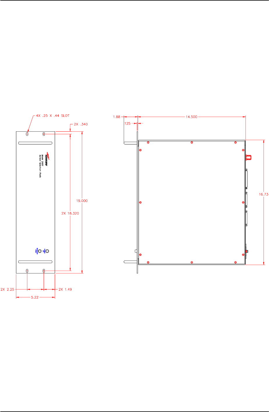
385700-1006-006 MECHANICAL INFORMATION
Document use is restricted to that described on cover 7-1
CHAPTER 7
MECHANICAL INFORMATION
7.1 BASE DATA RADIO MECHANICAL OUTLINE
The mechanical outline for the rack mounted version of the BDR, 385700-3000-001, is given
in Figure 7-1 BDR Rack Mount Mechanical Outline.
- 001
Figure 7-1 BDR Rack Mount Mechanical Outline
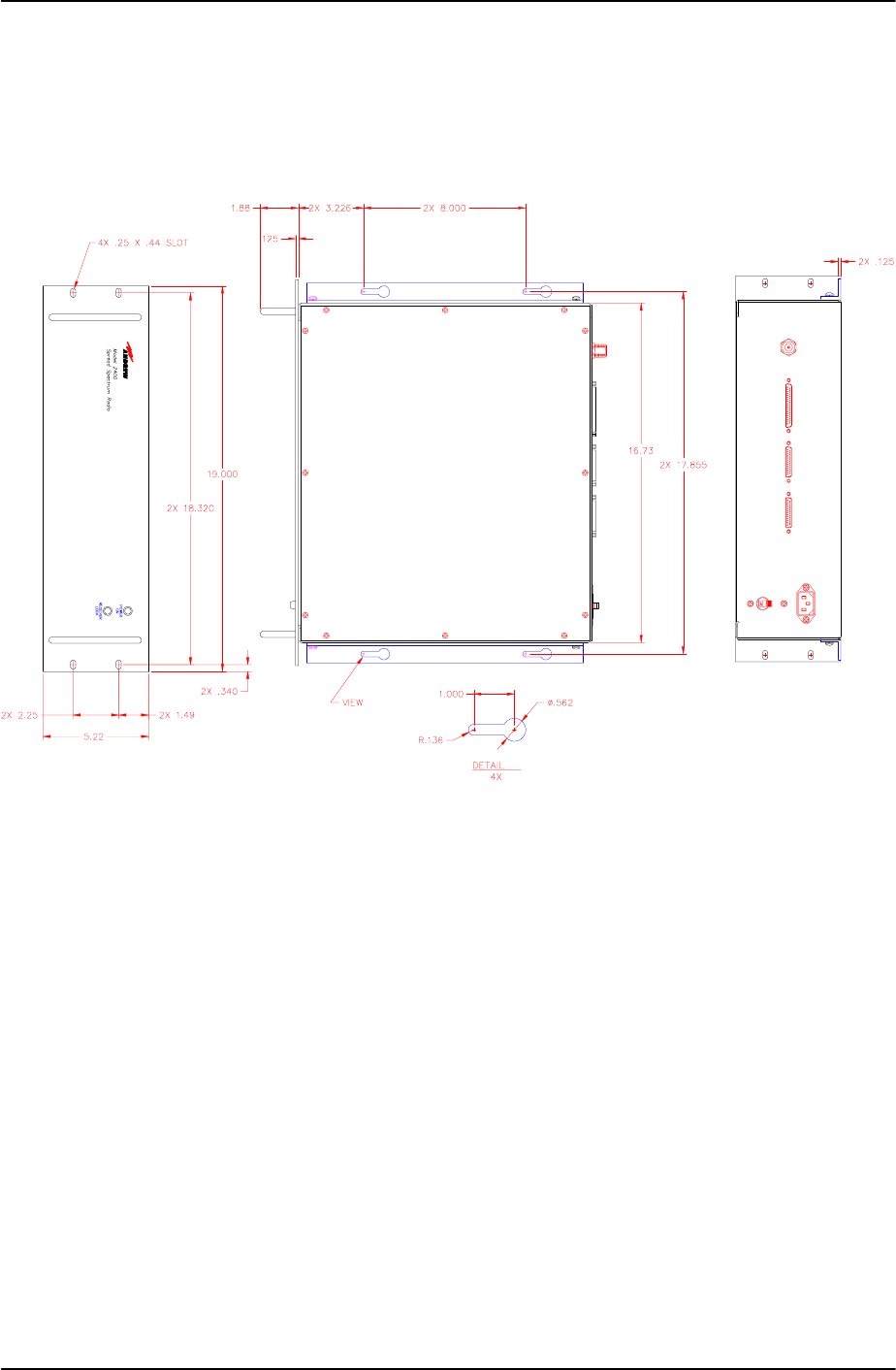
385700-1006-006 MECHANICAL INFORMATION
Document use is restricted to that described on cover 7-2
The mechanical outline for the wall mounted version of the BDR, 385700-3000-002, is given in
Figure 7-2 BDR Wall Mount Mechanical Outline.
POWER IN
J1
J2
DATA 1
J3
DATA 2
J4
DIAGNOSTIC J5
ANTENNA
CB1
A
A
- 002
Figure 7-2 BDR Wall Mount Mechanical Outline
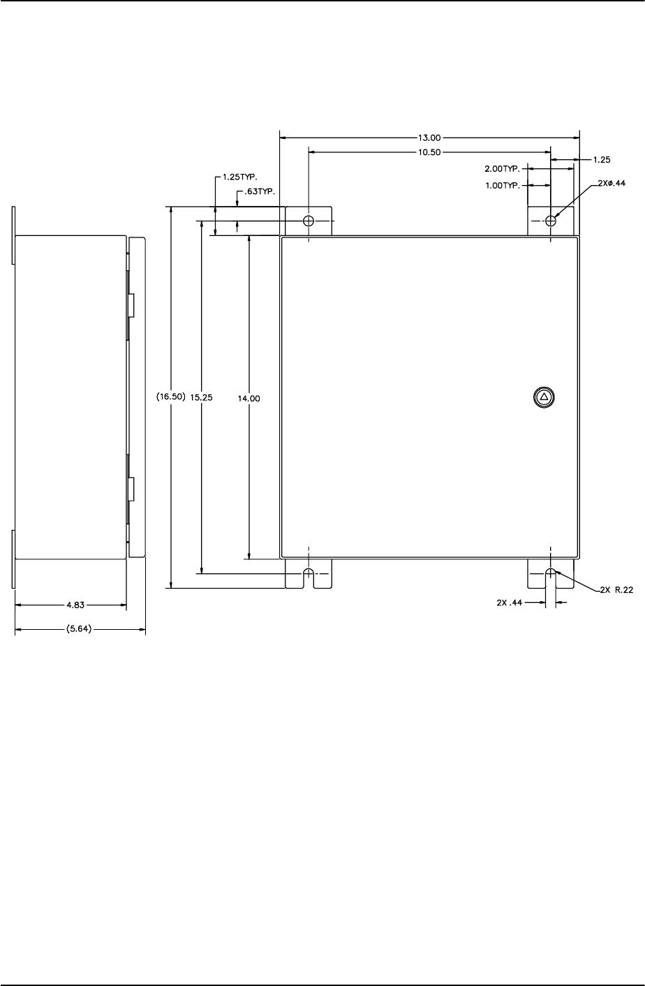

385700-1006-006 DIAGNOSTIC LCP MENU
Document use is restricted to that described on cover 8-1
CHAPTER 8
DIAGNOSTIC LCP MENU
8.1 DIAGNOSTIC MENU
Initial configuration and trouble shooting of the radio equipment is accomplished through the
Diagnostic port of a radio. A WYSE 100 compatible terminal or a computer running a terminal
emulation program is attached to the diagnostic port. This terminal or computer is referred to
as the LCP terminal elsewhere in this manual. The LCP diagnostics menu for the MDR and
BDR are identical except for a few commands. The differences are noted in the following
sections. The diagnostics menu includes user available selections as well as reserved
commands for testing the radio. The reserved commands are intended for use by factory
trained personnel only. Use of these commands by unauthorized personnel will require the
user to perform a power reset to the unit before normal operation can occur. The following
sections are based on a typical LCP menu. The user should contact the factory for updates.
The operator selects a particular command by typing the command number, which appears to
the left of the command, followed by pressing the ENTER (↵) key. If the command requires
additional parameters, the LCP program will prompt the user for inputs. All inputs are
completed using the ENTER (↵) key.

385700-1006-006 DIAGNOSTIC LCP MENU
Document use is restricted to that described on cover 8-2
BDR Diagnostic LCP Menu
Phase II WAYSIDE LCP MENU SW Ver #: 01.01
1 Send Poll Requests 21 A/D Select 41 Read Track
2 Set PN Index (CDMA Code) 22 Set Clock Search 42 Read AGC
3 Program Synthesizers 23 OS-9 Shell 43 Power
4 Reserved 24 Set RCS Address 44 Test EEPROM
5 Reset DSP 25 Reserved 45 Read PA/Temp
6 Reserved 26 SSR Status Request 46 Poll Response
7 Reset PN 27 System Block Status 47 Select Antenna
8 Reset PN (RX,STROBE) 28 Status Request 48 unused
9 Reserved 29 Show Poll Counters 49 unused
10 Set Upper Threshold 30 Clear Poll Counters 50 Read Memory
11 Upper Thres w/o PN Reset 31 Reserved
12 Set Lower Threshold 32 Read TRACK/AGC Values
13 Lower Thres w/o PN Reset 33 Set dBm Output Level
14 Set Lower Lock Threshold 34 Change dBm/DAC Values
15 Disable Transmitter 35 Serial EEPROM Display
16 Enable Transmitter 36 Save Current Settings
17 Load SC Register 37 Load TnD SC Register
18 Disable Test Port 38 Reserved
19 Enable Test Port 39 Toggle Temp Compensation
20 PN Test Select 40 Display System Log
Figure 8-1 BDR LCP Menu

385700-1006-006 DIAGNOSTIC LCP MENU
Document use is restricted to that described on cover 8-3
8.2 MDR DIAGNOSTIC LCP MENU
Phase II WAYSIDE LCP MENU SW Ver #: 01.01
1 Vehicle Addr. (Train ID) 21 A/D Select 41 Read Track
2 Set PN Index (CDMA Code) 22 Set Clock Search 42 Read AGC
3 Program Synthesizers 23 OS-9 Shell 43 Power
4 Reserved 24 Set RCS Address 44 Test EEPROM
5 Reset DSP 25 Reserved 45 Read PA/Temp
6 Reserved 26 SSR Status Request 46 Poll Response
7 Reset PN 27 System Block Status 47 Select Antenna
8 Reset PN (RX,STROBE) 28 Status Request 48 unused
9 Reserved 29 Show Poll Counters 49 unused
10 Set Upper Threshold 30 Clear Poll Counters 50 Read Memory
11 Upper Thres w/o PN Reset 31 Reserved
12 Set Lower Threshold 32 Read TRACK/AGC Values
13 Lower Thres w/o PN Reset 33 Set dBm Output Level
14 Set Lower Lock Threshold 34 Change dBm/DAC Values
15 Disable Transmitter 35 Serial EEPROM Display
16 Enable Transmitter 36 Save Current Settings
17 Load SC Register 37 Load TnD SC Register
18 Disable Test Port 38 Reserved
19 Enable Test Port 39 Toggle Temp Compensation
20 PN Test Select 40 Display System Log
Figure 8-2 MDR LCP Menu
8.3 LCP COMMANDS
A description of the commands, their applicability to BDR or MDR, and the required
response(s) to be entered are given below.
Send Poll Requests BDR
This command causes the BDR to send or stop sending poll requests to an MDR. The
poll request is sent to Vehicle Address 100016. The poll requests are sent at an
approximate rate of one request per second. The LCP displays the current state of the
polling after this command is entered. The polling state toggles between sending and
stopping poll requests each time the command is entered.
Vehicle Addr. (Train ID) MDR
This command is used to set the 16 bit address of an MDR. Each MDR requires a
unique vehicle address. The allowable address range is 000116 to FFFE16 . The
address, FFFF16, is reserved for the Broadcast message.

385700-1006-006 DIAGNOSTIC LCP MENU
Document use is restricted to that described on cover 8-4
Set PN Index (CDMA Code) BDR and MDR
This command selects the spreading code to be used by the Transmitter and Receiver
PN spreading generators. The user selects the generator(s), Tx, Rx, or Both to be
loaded, and an index number which points to a lookup table of PN generator initial
conditions. At the completion of this command, the selected PN generator(s) are
reset, the new initial conditions are loaded into the PN generator(s), and the radio
displays the new generator PN index.
Program Synthesizers BDR and MDR
This command is reserved for future use or internal unit testing.
Reserved BDR and MDR
This command is reserved for future use or internal unit testing.
Reset DSP BDR and MDR
This command is reserved for future use or internal unit testing.
Reset PN BDR and MDR
This command allows the user to start one of the PN sequences in the radio at a
known state. The user is prompted for the type of generator reset (continuous, pulsed,
or release from continuous) and which generator, Tx or Rx, to reset..
Reset PN (RX STROBE)
This command performs a pulsed reset of the Rx PN generator with a double
keystroke entry by the user.
SET UPPER THRESHOLD BDR and MDR
The upper threshold value is part of the radio receiver’s confidence test for determining
PN code synchronization. The UPPER THRESHOLD must be greater than the
LOWER and LOWER LOCK thresholds. The actual values used are set at the factory.
Large values for the upper threshold require input high signal levels. If the levels are
set too high, the radio will not be able to declare PN synchronization. If the levels are
set too low, the radio will falsely declare PN synchronization. This will degrade
communications throughput by increasing the amount of time to synchronize to the
incoming PN code. Using this command results in an internal radio receiver reset
condition. This forces a radio receiver to reacquire PN synchronization. The range of
allowable values is 0016 to FF16 subject to the above stated requirements.
UPPER THRES W/O PN RESET BDR and MDR
This command is similar to the Set Upper Threshold command except it does not force
the radio receiver to reacquire PN synchronization after the new threshold is loaded.
SET LOWER THRESHOLD BDR and MDR
The lower threshold value is part of the radio receiver’s confidence test for determining
PN code synchronization. The LOWER THRESHOLD must be less than the UPPER
THRESHOLD but greater than the LOWER LOCK thresholds. The actual values used
are set at the factory. Large values for the lower threshold require input high signal
levels. If the levels are set too high, the radio will not be able to declare PN
synchronization. If the levels are set too low, the radio will falsely declare PN

385700-1006-006 DIAGNOSTIC LCP MENU
Document use is restricted to that described on cover 8-5
synchronization. This will degrade communications throughput by increasing the
amount of time to synchronize to the incoming PN code or by preventing PN code
synchronization altogether. Using this command results in an internal radio receiver
reset condition, which forces a radio receiver resynchronization. The range of
allowable values is 0016 to FF16 subject to the above stated requirements.
LOWER THRES W/O PN RESET BDR and MDR
This command is similar to the Set Lower Threshold command except it does not force
the radio receiver to reacquire PN synchronization after the new threshold is loaded.
SET LOWER LOCK THRESHOLD BDR and MDR
The lower threshold value is part of the radio receiver’s confidence test for maintaining
PN code synchronization. The LOWER LOCK THRESHOLD must be less than the
UPPER THRESHOLD and is normally less than the LOWER LOCK thresholds. The
actual values used are set at the factory. Large values for the lower threshold require
input high signal levels. If the levels are set too high, the radio will not be able to
maintain PN synchronization. If the levels are set too low, the radio will falsely maintain
PN synchronization. This will degrade communications throughput by increasing the
amount of time to correctly synchronize to the incoming PN code or by preventing PN
code synchronization altogether. Using this command results in an internal radio
receiver reset condition, which forces a radio receiver resynchronization. The range of
allowable values is 0016 to FF16 subject to the above stated requirements.
DISABLE TRANSMITTER BDR and MDR
This command allows the user to manually turn off the radio transmitter.
ENABLE TRANSMITTER BDR and MDR
This command allows the user to manually turn on the radio transmitter. If the radio
has not been powered down, the output level will be the last loaded value. If the radio
is powered down after selecting this command, the output level will be the last value
saved to non volatile memory. The user can check the level with the STATUS
REQUEST command. The user can change the output level with the SET dBm
OUTPUT LEVEL command.
LOAD SC REGISTER BDR and MDR
This command is reserved for future use or internal unit testing.
DISABLE TEST PORT BDR and MDR
This command is reserved for future use or internal unit testing.
PN TEST SELECT BDR and MDR
This command is reserved for future use or internal unit testing.
A/D SELECT BDR and MDR
This command is reserved for future use or internal unit testing.
SET CLOCK SEARCH BDR and MDR
This command is reserved for future use or internal unit testing.

385700-1006-006 DIAGNOSTIC LCP MENU
Document use is restricted to that described on cover 8-6
OS-9 SHELL BDR and MDR
This command is reserved for future use or internal unit testing. The ESCAPE key is
used to return the radio to its normal operating condition from this state.
SET RCS ADDRESS BDR
This command sets the BDR address. It is used in multiple BDR configurations. The
allowable range of address is 0116 to FE16. A default address of 4016 is preloaded into
the BDR upon power up initialization. See the ICD for further information.
SSR STATUS REQUEST BDR and MDR
This command reads the current configuration data stored inside various modules
within the radio. It includes a display that indicates whether the data agrees with the
data originally written to the modules. The parameters currently supported are the
lower lock, lower, and upper thresholds, the Tx and Rx PN code, the Tx and Rx Data
Rates, and the current state of the Transmitter. All other parameters are for future
use.
STATUS REQUEST BDR and MDR
This command displays the current radio configuration as stored in the radio’s volatile
memory. The parameters currently supported are the lower lock, lower, and upper
thresholds, the Tx and Rx PN code, the Tx and Rx Data Rates, and the current state
of the Transmitter. All other parameters are for future use.
SHOW POLL COUNTERS BDR
This command displays a group of communication counters that monitor the polling
activity between the BDR and MDR and special flags used for internal radio code
debugging. The counter types currently supported are the number of poll requests
input to the BDR, the number of frames transmitted from the BDR controller to the
radio RF transmitter, the number of valid poll responses received from the MDR, the
total number of frames received from the radio RF port at the BDR controller, and the
number of poll request retransmission attempts.
CLEAR POLL COUNTERS
This command zeroes a group of communication counters that monitor the polling
activity between the BDR and MDR.
READ TRACK/AGC VALUES BDR and MDR
This command is reserved for future use or internal unit testing.
SET dBM OUTPUT LEVEL BDR and MDR
This command is used to set the transmitter output power level of the radio. The
range of listed output levels may be greater than the specifications of the radio. When
using this command, the user must set the output level such that compliance with FCC
output level requirements are maintained. The output resolution is in 1 dB increments.
CHANGE dBM/DAC VALUES BDR and MDR
This command is reserved for factory calibration or internal unit testing. The
command, Set dBM Output Level, is used to enter the PA control voltages
corresponding to an RF output levels. After entering the voltage/ RF levels, the user

385700-1006-006 DIAGNOSTIC LCP MENU
Document use is restricted to that described on cover 8-7
must save the entries to non volatile memory using the SAVE CURRENT SETTINGS
command.
SERIAL EEPROM DISPLAY BDR and MDR
This command displays the radio configuration parameters stored in the non volatile
memory of the radio. These are the parameters loaded into the radio upon applying
power to the unit.
SAVE CURRENT SETTINGS BDR and MDR
This command writes the current radio configuration parameters to the non volatile
memory of the radio.
LOAD TND SC REGISTER BDR and MDR
This command is reserved for future use or internal unit testing.
TOGGLE TEMP COMPENSATION BDR and MDR
This command is reserved for future use or internal unit testing.
DISPLAY SYSTEM LOG BDR and MDR
This command is reserved for future use or internal unit testing.
Read Track BDR and MDR
This command is reserved for future use or internal unit testing.
Read AGC BDR and MDR
This command is reserved for future use or internal unit testing.
Power BDR and MDR
This command is reserved for future use or internal unit testing.
Test EEPROM BDR and MDR
This command performs a non destructive test of the EEprom circuitry.
Read PA/Temp BDR and MDR
This command is reserved for future use or internal unit testing.
Poll Response MDR
This command toggles the MDR poll response state between enabling and disabling a
fixed command response. Enabling the fixed poll response configures the radio to
transmit an 81 byte message whenever the MDR receives a valid poll request from the
BDR.

385700-1006-006 DIAGNOSTIC LCP MENU
Document use is restricted to that described on cover 8-8
Select Antenna MDR
This command sends a binary encoded value to the ANTn lines of the MDR Data 2
port. The ANTn lines are 20 ma driver control lines. The truth table for selecting the
ANTn lies is given below:
Select Antenna Value ANTn line selected
1ANT0
4ANT1
8ANT2
Unused BDR and MDR
This command is reserved for future use or internal unit testing.
Read Memory BDR and MDR
This command is reserved for future use or internal unit testing.