Andrew N4-US80D-RXL24 Radio Base Station for WCDMA User Manual DOC001 DE14 OneBase Pico NodeB installation
Andrew AB Radio Base Station for WCDMA DOC001 DE14 OneBase Pico NodeB installation
UserManual.wiki
>
Andrew
>
N4 US80D RXL24 User Manual
Manual
Navigation menu
Upload a User Manual
Namespaces
Wiki Guide
HTML
PDF
Info
Views
User Manual
Discussion / Help
Navigation
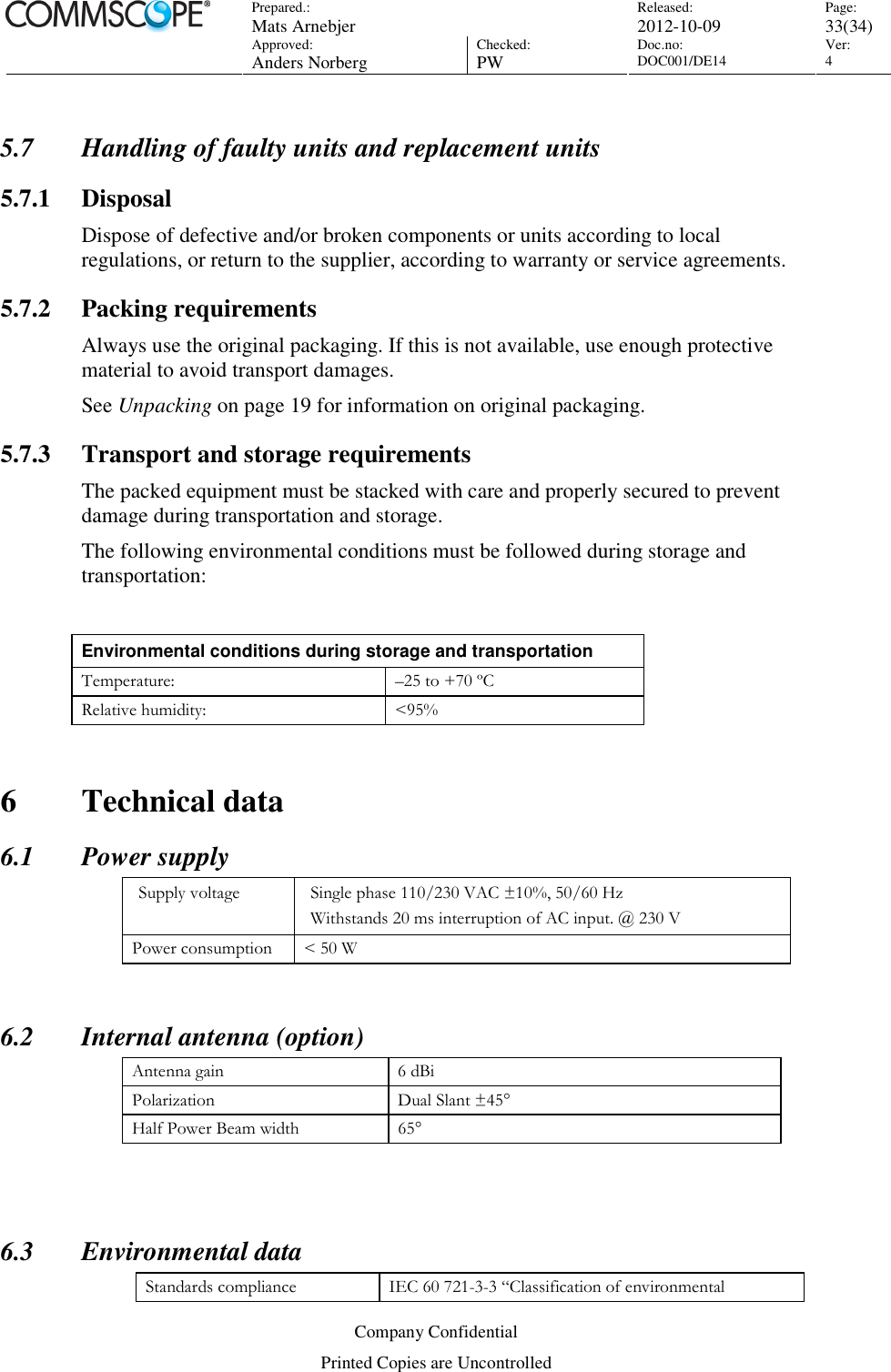
![Prepared.: Mats Arnebjer Released: 2012-10-09 Page: 4(34) Approved: Anders Norberg Checked: PW Doc.no: DOC001/DE14 Ver: 4 Company Confidential Printed Copies are Uncontrolled 1 Document Data 1.1 Revision History Ver. Date Author Reviewers (FR indicated) Comments 1 2006-10-13 Åke Jernberger A. Declercq Created when splitting DOC001/DE01 into a “installation manual” (this document) and a dedicated“ commissioning manual” 2 2007-01-12 Erik Blom Å Jernberger, Erik Blom(FR) Added information needed for safety approval in Nordic Countries. 3 2011-10-07 Mats Arnebjer Peter Wahlström Only IP versions 4 2012-10-09 Mats Arnebjer Peter Wahlström Correction updates 1.2 References Reference Doc no Title [Pico-description] DOC001/DE04 “Description OneBASE Pico Node B” [O&M-manual] DOC001/DE02 “Operation and maintenance manual for OneBASE Node B” [LMT-manual] DOC001/DE03 “Manual for Local maintenance tool for OneBASE Node B” [office-data-manual] DOC001/DE05 “Office data parameters for OneBASE Node B” [alarm-list] DOC001/DE08 “OneBASE Node B alarms” [commissioning-manual] DOC001/DE11 “Manual for commissioning of OneBASE Node B”](https://usermanual.wiki/Andrew/N4-US80D-RXL24/User-Guide-2101292-Page-4.png)
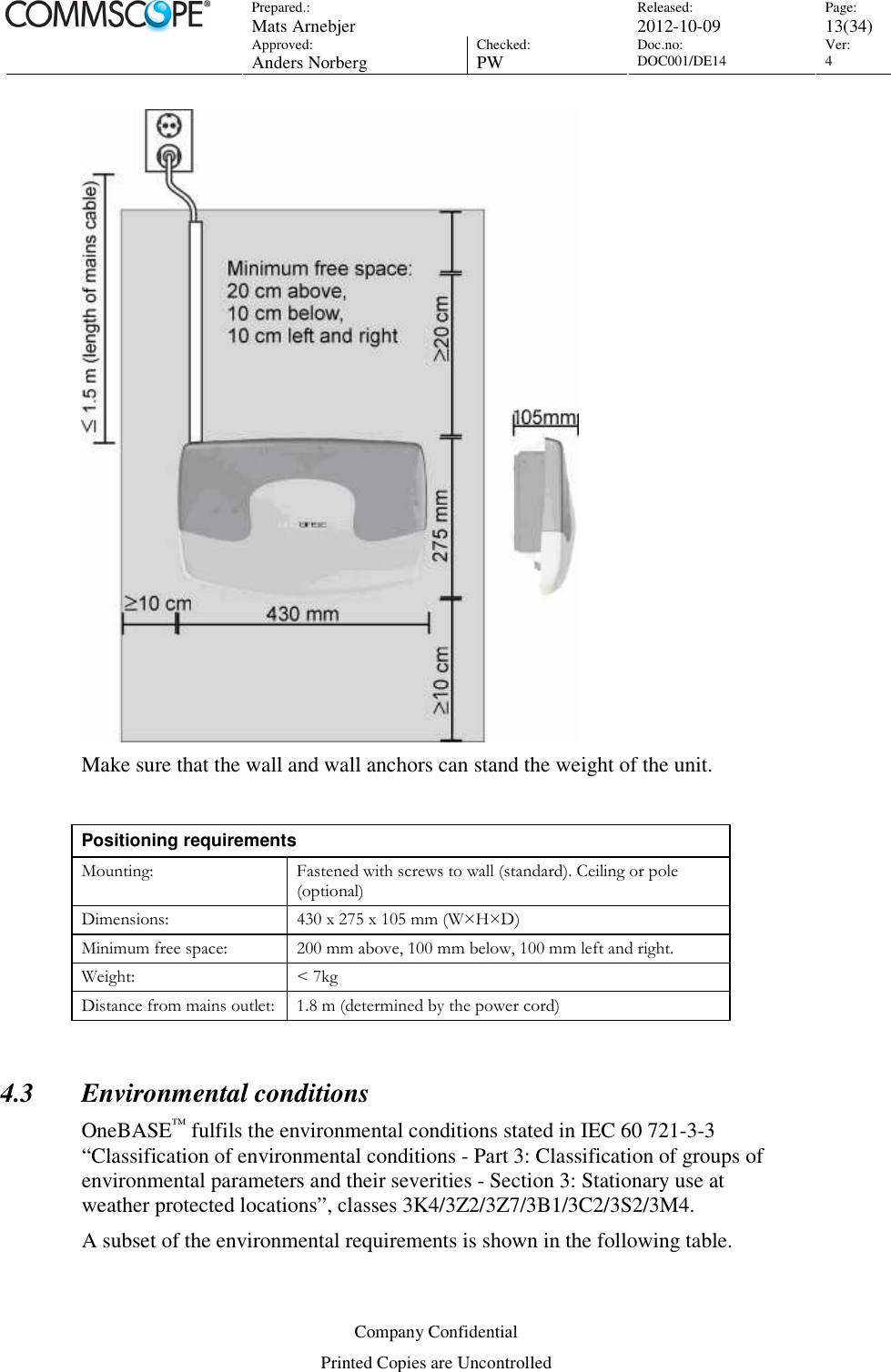
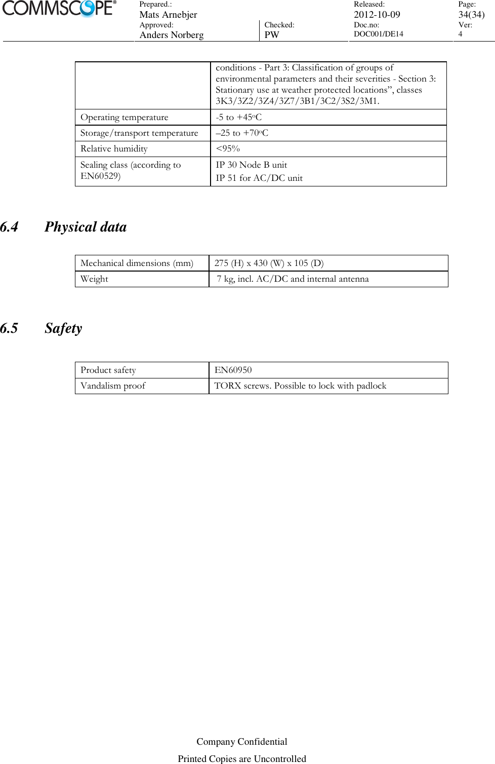
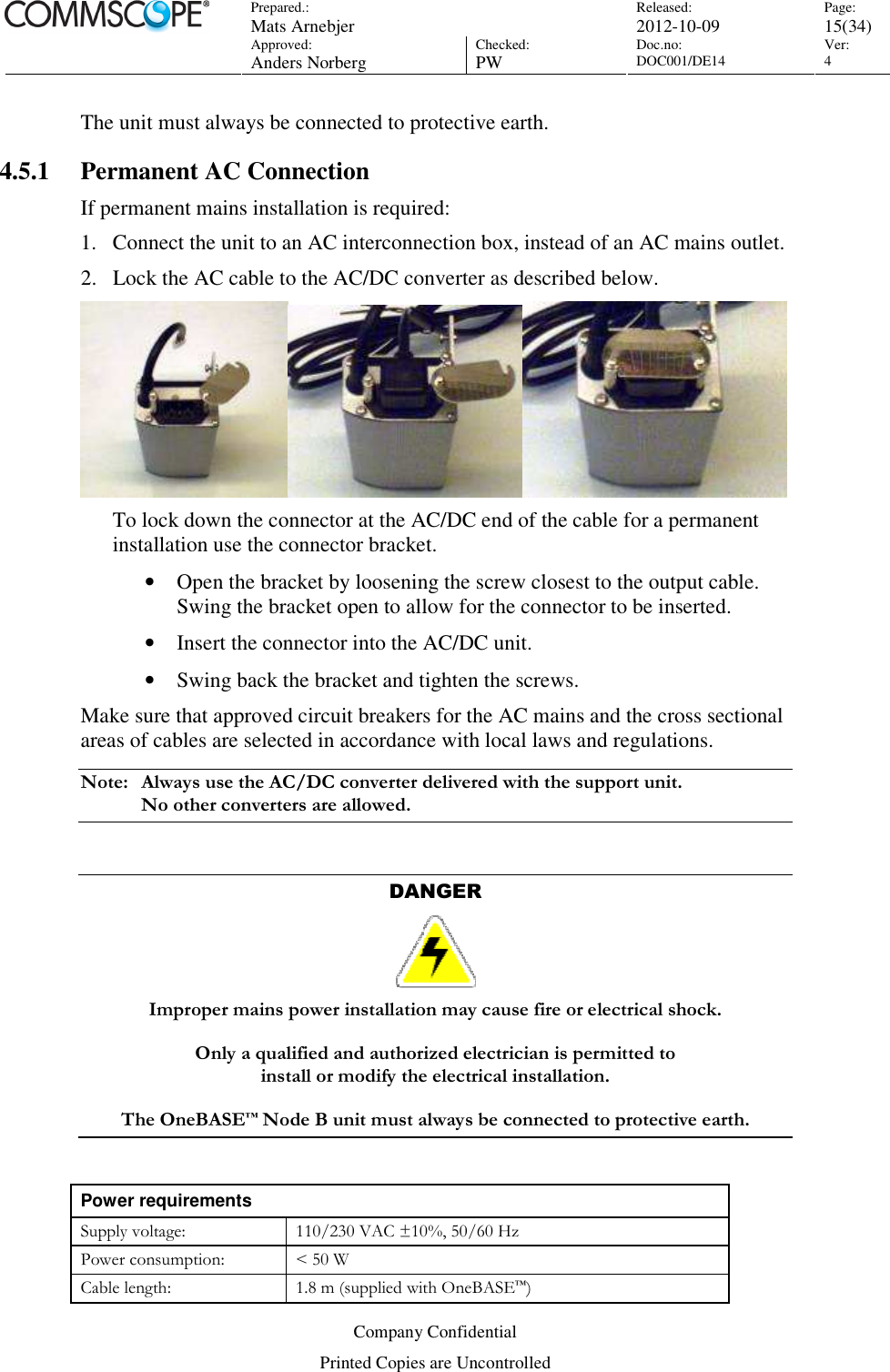
![Prepared.: Mats Arnebjer Released: 2012-10-09 Page: 14(34) Approved: Anders Norberg Checked: PW Doc.no: DOC001/DE14 Ver: 4 Company Confidential Printed Copies are Uncontrolled Environmental requirements (subset of IEC 60 721-3-3) Ambient temperature: -5 to +45 °C Relative humidity: <95% Dust proof: Yes, no impact on the operation. Heat dissipation: < 50W Sealing class (according to EN 60529) IP 30 Node B Unit IP 51 Power Supply 4.4 IP/Ethernet Transport The transport interface (Iub) on the OneBASE™ Node B is Ethernet over a twisted pair cable connected to a RJ45-socket. The socket has a yellow LED for transmission indication. Make sure the site is equipped with a Local Area Network connection as close as possible to the OneBASE™ Node B. The IP properties to be used must be configured during commissioning of the OneBASE™ Node B. See reference [commissioning-manual] and [office-data-manual]. The type of cable to use is a CAT5 or CAT6 twisted pair cable with symmetrical wiring and an impedance of 100 Ohm. Preferably use shielded cable. The pinning follows the standard for a RJ-45 port. 4.5 Mains power OneBASE™ is delivered with a mains cable with an IEC 60320 C15 connector in one end for connection to the AC/DC unit and either an open end or an AC Mains plug in the other end. The site should be equipped with an easily accessible earthed AC mains outlet or an AC interconnect box with protective earth, as applicable, within range of the OneBASE™ Node B unit.](https://usermanual.wiki/Andrew/N4-US80D-RXL24/User-Guide-2101292-Page-14.png)
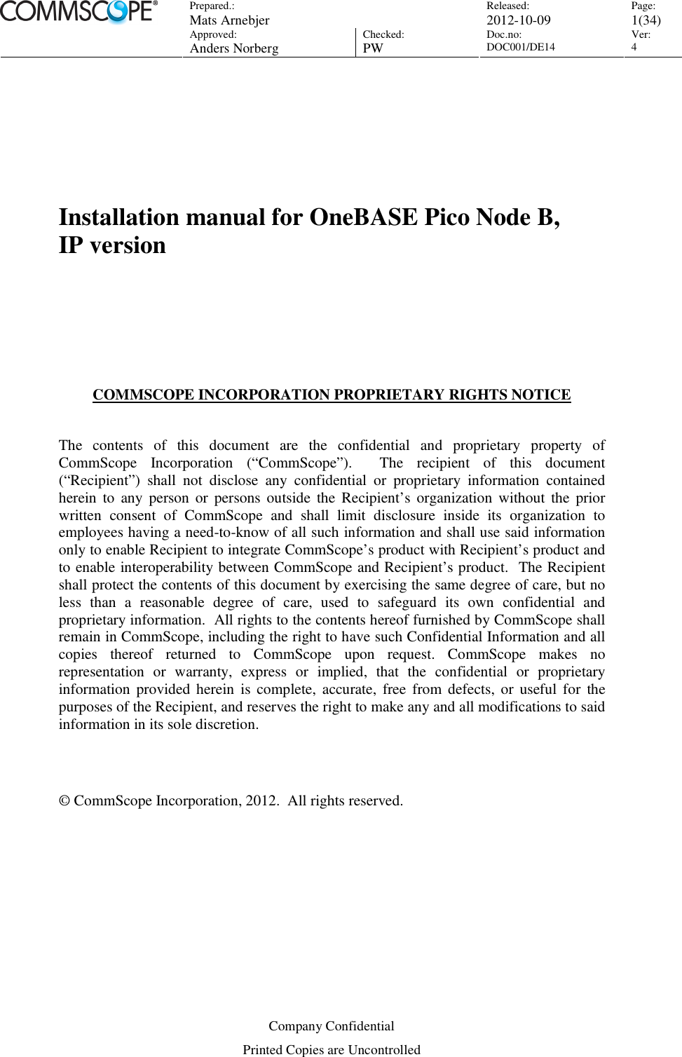
![Prepared.: Mats Arnebjer Released: 2012-10-09 Page: 16(34) Approved: Anders Norberg Checked: PW Doc.no: DOC001/DE14 Ver: 4 Company Confidential Printed Copies are Uncontrolled 4.6 External alarms OneBASE™ is equipped with an alarm connector for connecting two external alarms. The type of alarms used must be configured by setting the name, function, and severity of the two alarms in the OneBASE™ Node B Office Data. See reference [commissioning-manual] and [office-data-manual] By default the alarms are set to “Not used”. The alarm circuits can be defined as normally open or normally closed and when the alarm is activated an alarm notification is sent to NNM/OMC. The alarm inputs are galvanic isolated. External alarm trig points Sensed impedance State Current/Voltage <200 Ohm Closed 10 mA (typical) > 2 kOhm Open 3.0 V (typical) The supplied connector/plug is a 4-position terminal block connector (AMP 28513-4). Twisted pair cables should be used (2-wire or 4-wire). The wire ends are inserted into the plug and fixed with screws. 4.7 External antennas The OneBASE™ Node B unit may be used with external antennas. Since the unit includes duplex filters to provide receiver diversity, no external duplex filters are needed. The OneBASE™ Node B unit is provided with two female QMA connectors. Antenna cables with angled (90°) male plugs should be used. The type of cables to use depends on antenna gain, distance, acceptable loss etc. Refer to recommendations from antenna supplier.](https://usermanual.wiki/Andrew/N4-US80D-RXL24/User-Guide-2101292-Page-16.png)