Andrew N4-US80D-RXL24 Radio Base Station for WCDMA User Manual DOC001 DE14 OneBase Pico NodeB installation
Andrew AB Radio Base Station for WCDMA DOC001 DE14 OneBase Pico NodeB installation
Andrew >
Manual

Prepared.:
Mats Arnebjer
Released:
2012-10-09
Page:
1(34)
Approved:
Anders Norberg
Checked:
PW
Doc.no:
DOC001/DE14 Ver:
4
Company Confidential
Printed Copies are Uncontrolled
Installation manual for OneBASE Pico Node B,
IP version
COMMSCOPE INCORPORATION PROPRIETARY RIGHTS NOTICE
The contents of this document are the confidential and proprietary property of
CommScope Incorporation (“CommScope”). The recipient of this document
(“Recipient”) shall not disclose any confidential or proprietary information contained
herein to any person or persons outside the Recipient’s organization without the prior
written consent of CommScope and shall limit disclosure inside its organization to
employees having a need-to-know of all such information and shall use said information
only to enable Recipient to integrate CommScope’s product with Recipient’s product and
to enable interoperability between CommScope and Recipient’s product. The Recipient
shall protect the contents of this document by exercising the same degree of care, but no
less than a reasonable degree of care, used to safeguard its own confidential and
proprietary information. All rights to the contents hereof furnished by CommScope shall
remain in CommScope, including the right to have such Confidential Information and all
copies thereof returned to CommScope upon request. CommScope makes no
representation or warranty, express or implied, that the confidential or proprietary
information provided herein is complete, accurate, free from defects, or useful for the
purposes of the Recipient, and reserves the right to make any and all modifications to said
information in its sole discretion.
© CommScope Incorporation, 2012. All rights reserved.

Prepared.:
Mats Arnebjer
Released:
2012-10-09
Page:
2(34)
Approved:
Anders Norberg
Checked:
PW
Doc.no:
DOC001/DE14 Ver:
4
Company Confidential
Printed Copies are Uncontrolled
Contents
1
DOCUMENT DATA .............................................................................................................4
1.1
R
EVISION
H
ISTORY
.........................................................................................................4
1.2
R
EFERENCES
...................................................................................................................4
2
GENERAL..............................................................................................................................5
2.1
A
BOUT THIS MANUAL
......................................................................................................5
2.2
CE
CONFORMANCE
.........................................................................................................5
2.3
FCC................................................................................................................................5
2.3.1
Part 15 – Class B digital device or peripheral..........................................................5
2.4
S
AFETY AND WARNINGS
..................................................................................................5
2.4.1
General......................................................................................................................5
2.4.2
High voltage ..............................................................................................................6
2.4.3
Electromagnetic radiation.........................................................................................6
2.4.4
Equipment alterations ...............................................................................................7
3
PRODUCT OVERVIEW......................................................................................................8
3.1
G
ENERAL
........................................................................................................................8
3.2
M
ECHANICAL DESIGN
.....................................................................................................9
3.3
C
ONNECTORS AND
LED
S
..............................................................................................11
3.3.1
Front panel..............................................................................................................11
4
SITE PREPARATION........................................................................................................12
4.1
P
REREQUISITES
.............................................................................................................12
4.2
P
OSITIONING
.................................................................................................................12
4.3
E
NVIRONMENTAL CONDITIONS
.....................................................................................13
4.4
IP/E
THERNET
T
RANSPORT
............................................................................................14
4.5
M
AINS POWER
...............................................................................................................14
4.5.1
Permanent AC Connection......................................................................................15
4.6
E
XTERNAL ALARMS
......................................................................................................16
4.7
E
XTERNAL ANTENNAS
..................................................................................................16
4.8
O
THER EXTERNAL EQUIPMENT
......................................................................................17
5
INSTALLATION.................................................................................................................18
5.1
P
REREQUISITES
.............................................................................................................18
5.2
P
RECAUTIONS
...............................................................................................................18
5.3
I
NSTALLATION TOOLS AND MATERIAL
..........................................................................18
5.4
U
NPACKING
..................................................................................................................19
5.4.1
Installing the internal antenna (optional)................................................................19
5.5
M
OUNTING
....................................................................................................................20
5.5.1
Wall mounting .........................................................................................................20
5.5.2
Pole or ceiling mounting .........................................................................................27
5.6
R
EPLACEMENT OF UNITS
...............................................................................................29
5.6.1
Replacing OneBASE
™
Node B unit .........................................................................29
5.6.2
Replacing internal antenna .....................................................................................30
5.6.3
Replacing cover.......................................................................................................31
5.6.4
Replacing AC/DC converter....................................................................................31
5.7
H
ANDLING OF FAULTY UNITS AND REPLACEMENT UNITS
..............................................33
5.7.1
Disposal...................................................................................................................33
5.7.2
Packing requirements..............................................................................................33
5.7.3
Transport and storage requirements .......................................................................33
6
TECHNICAL DATA...........................................................................................................33
6.1
P
OWER SUPPLY
.............................................................................................................33
6.2
I
NTERNAL ANTENNA
(
OPTION
) ......................................................................................33

Prepared.:
Mats Arnebjer
Released:
2012-10-09
Page:
3(34)
Approved:
Anders Norberg
Checked:
PW
Doc.no:
DOC001/DE14 Ver:
4
Company Confidential
Printed Copies are Uncontrolled
6.3
E
NVIRONMENTAL DATA
................................................................................................33
6.4
P
HYSICAL DATA
............................................................................................................34
6.5
S
AFETY
.........................................................................................................................34

Prepared.:
Mats Arnebjer
Released:
2012-10-09
Page:
4(34)
Approved:
Anders Norberg
Checked:
PW
Doc.no:
DOC001/DE14 Ver:
4
Company Confidential
Printed Copies are Uncontrolled
1 Document Data
1.1 Revision History
Ver. Date Author Reviewers
(FR indicated)
Comments
1 2006-10-13 Åke
Jernberger A. Declercq Created when splitting
DOC001/DE01 into a “installation
manual” (this document) and a
dedicated“ commissioning manual”
2 2007-01-12 Erik Blom Å Jernberger, Erik
Blom(FR) Added information needed for
safety approval in Nordic
Countries.
3 2011-10-07 Mats
Arnebjer Peter Wahlström Only IP versions
4 2012-10-09 Mats
Arnebjer Peter Wahlström Correction updates
1.2 References
Reference Doc no Title
[Pico-description] DOC001/DE04 “Description OneBASE Pico Node B”
[O&M-manual] DOC001/DE02 “Operation and maintenance manual for OneBASE Node B”
[LMT-manual] DOC001/DE03 “Manual for Local maintenance tool for OneBASE Node B”
[office-data-manual]
DOC001/DE05 “Office data parameters for OneBASE Node B”
[alarm-list] DOC001/DE08 “OneBASE Node B alarms”
[commissioning-
manual] DOC001/DE11 “Manual for commissioning of OneBASE Node B”

Prepared.:
Mats Arnebjer
Released:
2012-10-09
Page:
5(34)
Approved:
Anders Norberg
Checked:
PW
Doc.no:
DOC001/DE14 Ver:
4
Company Confidential
Printed Copies are Uncontrolled
2 General
2.1 About this manual
This manual describes installation and maintenance of OneBASE™ Pico Node B.
The manual is intended for on-site installation and maintenance personnel.
2.2 CE conformance
Hereby, CommScope, declares that this OneBASE™ Pico Node B is in
compliance with the essential requirements and other relevant provisions of
Directive 1999/5/EC.
2.3 FCC
2.3.1 Part 15 – Class B digital device or peripheral
This equipment has been tested and found to comply to with the limits for Class B
digital device, pursuant to part 15 of the FCC Rules. These limits are designed to
provide reasonable protection against harmful interference in a residential
installation. This equipment generates, uses and can radiate radio frequency
energy and, if not installed and used in accordance with the instructions, may
cause harmful interference to radio communications. However, there is no
guarantee that interference will not occur in a particular installation. If this
equipment does, cause harmful interference to radio or television reception, which
can be determined by turning the equipment of and on, the user is encouraged to
try to correct the interference by one or more of the following measures: -Reorient
or relocate the receiving antenna. –Increase the separation between the equipment
and receiver. –Connect the equipment into an outlet on a circuit different from that
to which the receiver in connected. –Consult the dealer or an experienced
radio/TV technician for help.
2.4 Safety and warnings
The safety information provided in this manual is a supplement to local
regulations and is only valid for the OneBASE™ Node B. Any other equipment
supplied by CommScope or any local supplier may have its own safety
instructions. Study all instructions carefully before starting work.
2.4.1 General
Prepared.:
Mats Arnebjer
Released:
2012-10-09
Page:
6(34)
Approved:
Anders Norberg
Checked:
PW
Doc.no:
DOC001/DE14 Ver:
4
Company Confidential
Printed Copies are Uncontrolled
CAUTION
Make sure that local regulations on safety and
installation methods are known and followed.
Note: Failure to follow the requirements, instructions or local regulations may void
the product warranty and may expose the equipment owner or the service
provider to legal and financial liabilities.
CommScope and its resellers or distributors are not liable for injury, damage or
violation of regulations associated with the installation of the equipment in
breach with instructions or local regulations.
2.4.2 High voltage
WARNING
Improper mains power installation may cause fire or electrical shock.
Only a qualified and authorized electrician is permitted to install or
modify the mains installation.
2.4.3 Electromagnetic radiation
The OneBASE™ internal antenna transmits radio energy during normal operation.
The output power is less than 250 mW and the energy level even at close distance
is well below the recommended exposure limits for the general public.
The safety distance to fulfill the occupational exposure limits (OEL) is 0.2 m. This
means that it is recommended to not stand or work closer than 0.2 m from the
front of the internal antenna for extended periods of time.

Prepared.:
Mats Arnebjer
Released:
2012-10-09
Page:
7(34)
Approved:
Anders Norberg
Checked:
PW
Doc.no:
DOC001/DE14 Ver:
4
Company Confidential
Printed Copies are Uncontrolled
2.4.4 Equipment alterations
Note: The casing of the OneBASE
™
Node B unit may on no occasion be opened. In
case the sealing has been broken CommScope voids the product warranty and
assumes no responsibility of the safety.
Note: The OneBASE
™
Node B may not be covered, painted, or altered in any way.
Ensure sufficient airflow for ventilation.
Prepared.:
Mats Arnebjer
Released:
2012-10-09
Page:
8(34)
Approved:
Anders Norberg
Checked:
PW
Doc.no:
DOC001/DE14 Ver:
4
Company Confidential
Printed Copies are Uncontrolled
3 Product overview
3.1 General
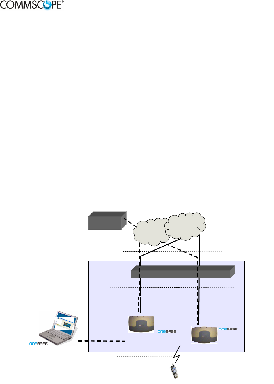
OneBASE™ Pico Node B is a complete pico cell radio base station intended to
enhance coverage and increase capacity in 3G (UMTS) systems. The OneBASE™
Pico Node B connects to the UTRAN system using the Iub interface.
If the UTRAN operation and maintenance system (OMC) has integrated support
for OneBASE™ Node B, then this can be used for centralized operation and
maintenance.
Local configuration is handled with the Local Management Tool – LMT. The
LMT runs on a standard portable PC and is connected directly to an OneBASE™
Node B unit through an Ethernet interface.
For remote control it is possible to use an LMT via the same IP network as would
be used for used centralized operation and maintenance.
An NTP (Network Time Protocol) Server is required in order to get the correct
time in the Node B. Each Node B has an NTP client which fetches the correct
time from the NTP Server.
RNC
O&M IP
Network
Core
Network
Iub (IP)
Iu
NTP Server
serS
Serv
Local
Management
Tool (LMT)
L
ocal
Management
Tool (LMT)
Uu
User
Equipment
Radio Access
Network (UTRAN)
Pico
Node B
Pico
Node
B
Pico Node B
Prepared.:
Mats Arnebjer
Released:
2012-10-09
Page:
9(34)
Approved:
Anders Norberg
Checked:
PW
Doc.no:
DOC001/DE14 Ver:
4
Company Confidential
Printed Copies are Uncontrolled
3.2 Mechanical design
OneBASE™ is designed for indoor use in both office environments and public
areas like malls, airports, arenas, garages, etc. The compact size and light weight
makes it easy to place. The power consumption is low and since it uses self-
convection cooling it is completely noise free.
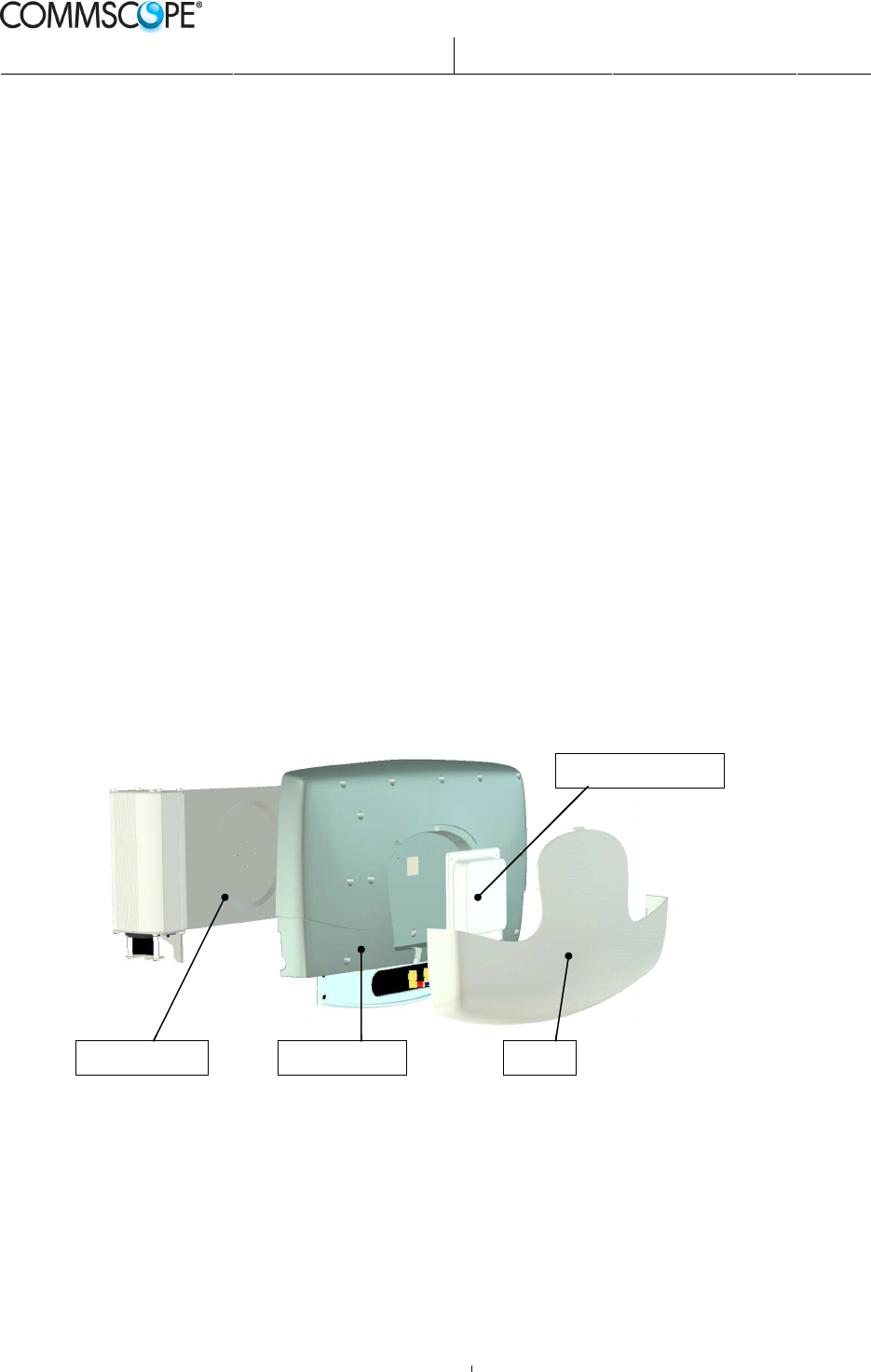
A complete OneBASE™ Pico Node B consists of:
• Node B unit
• Support unit, including AC/DC converter
• Internal antenna (optional)
• Cover
• Mains cable
The Node B unit contains all electronics and interface connectors. Integrated with
the Node B unit is an optional internal antenna. External antennas may be used
instead of the internal antenna, which then is omitted.
The support unit must always be used for mounting the OneBASE™ Node B unit
to a wall. Optionally, mounting equipment for mounting in a ceiling or on a pole
is available. The support unit includes an AC/DC converter and a mains cable
with the mains end open or fitted with a protective earth plug.
The purpose of the cover is to give OneBASE™ esthetical exterior with or
without the optional internal antenna fitted. The color of the standard cover is light
gray.
Support Unit Node B Unit Cover
Internal Antenna
Support Unit Node B Unit Cover
Internal Antenna
Installation overview
OneBASE™ is easy to install and maintain. The supplied support unit is typically
screwed onto a wall and the Node B unit is hanged onto the support unit. The
Node B unit is connected to a standard mains outlet and one or two transmission
interface outlets.
Optional equipment may be ordered for mounting to the ceiling or on a pole.
Prepared.:
Mats Arnebjer
Released:
2012-10-09
Page:
10(34)
Approved:
Anders Norberg
Checked:
PW
Doc.no:
DOC001/DE14 Ver:
4
Company Confidential
Printed Copies are Uncontrolled
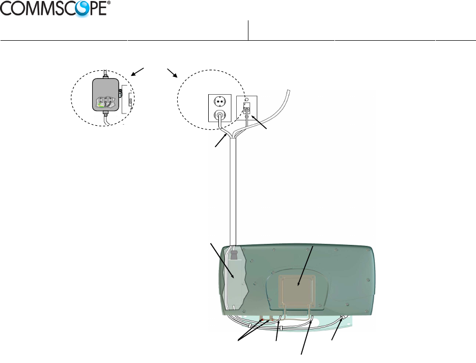
Transmission interface (E1/T1/J1)
Grounded
mains outlet
110/230 VAC
Transmission connector (RJ45)
AC/DC converter Internal antenna
DC power (12V) Antenna connectors (SMA)
Standard mains cable
(1.8 m)
Alarm cable (from external alarms)
External alarms connector
110/230 VAC
Fixed AC
Connection
Alternatives
Antenna connectors QMA
Configuration is done with the Local Management Tool (LMT), which is a
software application on a standard portable PC connected through a standard
Ethernet adapter directly to the OneBASE
™
Node B unit. Initial configuration
may be done before taking the OneBASE
™
Node B unit to the installation site, or
on site in connection with the hardware installation.
Periodic on site maintenance is normally not required.
Prepared.:
Mats Arnebjer
Released:
2012-10-09
Page:
11(34)
Approved:
Anders Norberg
Checked:
PW
Doc.no:
DOC001/DE14 Ver:
4
Company Confidential
Printed Copies are Uncontrolled
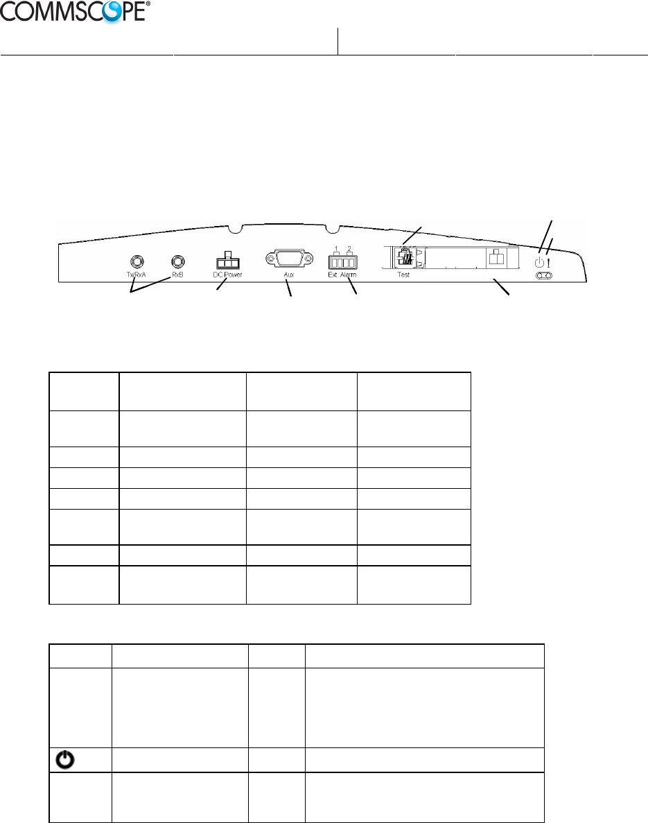
3.3 Connectors and LEDs
3.3.1 Front panel
The picture below shows the location of the OneBASE
™
external connectors and
LEDs
PCM A PCM B
Test
, only for production use Power ON
,
Green LED
Error
,Red LED
RF
BTS Console (RS485)
Ethernet for
- Iub
- LMT
DC Supply Power
,
Iub/LMT
External alarm input
PCM A PCM B
Test
, only for production use Power ON
,
Green LED
Error
,Red LED
RF
BTS Console (RS485)
Ethernet for
- Iub
- LMT
DC Supply Power
,
Ethernet
External alarm input
PCM A PCM B
Test
, only for production use Power ON
,
Green LED
Error
,Red LED
RF
BTS Console (RS485)
Ethernet for
- Iub
- LMT
DC Supply Power
,
Iub/LMT
External alarm input
PCM A PCM B
Test
, only for production use Power ON
,
Green LED
Error
,Red LED
RF
BTS Console (RS485)
Ethernet for
- Iub
- LMT
DC Supply Power
,
Ethernet
External alarm input
3.3.1.1 Connectors
Label Interface Type of
connector
Tx/RxA Antenna connector A Antenna RF,
Tx/RxA
QMA
RxB Antenna connector B Antenna RF, RxB QMA
DC-Power
Power supply 12 V DC Mini Fit JR
Aux BTS consol RS485 DSUB-9
Ext.Alarm External alarms
connector
4-pos terminal
block
Test Test (not used) RJ11
Ethernet Transmission
connector
Ethernet
100 BASE-TX
RJ45
3.3.1.2 LEDs
Label Color Description
Ethernet Ethernet LED
(in Ethernet connector)
Yellow Steady light: Ethernet line connection
established, no transmission
Flickering: When any transmitting or
receiving Ethernet physical
layer data frame is detected
Power ON Green Mains power ON
!
Error LED Red Steady light: Node B faulty
Blinking: Node B software load failure
(Node B in boot mode)

Prepared.:
Mats Arnebjer
Released:
2012-10-09
Page:
12(34)
Approved:
Anders Norberg
Checked:
PW
Doc.no:
DOC001/DE14 Ver:
4
Company Confidential
Printed Copies are Uncontrolled
4 Site preparation
4.1 Prerequisites
The site of the OneBASE
™
Base Station should be planned in advance on the
basis of radio coverage and capacity needs. Refer to relevant information for:
• Details on positioning of OneBASE
™
and any external equipment and external
antennas, including antenna direction(s).
• Earthed mains power source.
• Local Area Network, LAN.
Information on configuration details regarding parameters to set during
commissioning of individual OneBASE
™
Node B units.
4.2 Positioning
If the internal antenna is used, the desired coverage and direction of the antenna
determine the positioning of the OneBASE
™
Node B unit. With external antennas
the OneBASE
™
Node B unit can be positioned more freely.
Note: Always use the supplied support unit to fit the OneBASE
™
Node B unit, and
always mount the support unit vertically for sufficient cooling.
Never mount the OneBASE
™
Node B unit horizontally, even if the internal
antenna is not used.
OneBASE
™
is designed for “stationary use at weather protected locations”. This
means that it can be positioned in normal indoor environments like offices, hotels
or shopping malls, but it may also be used in semi-indoor environments like train
stations, subways, garages, etc. as long as the area fulfils the environmental
requirements of OneBASE
™
. See Environmental conditions on page 13 for
details.
The supplied support unit is used for fitting the OneBASE
™
Node B unit on a
wall. Optionally, mounting equipment for mounting in a ceiling or on a pole is
available.
The Node B unit can be locked to the support unit by using a padlock.
The unit should be installed within reach of a Local Area Network access point
and within reach of an earthed mains outlet. The unit is delivered with a power
cord with or without connector. Cables can be inserted from top or bottom on the
left side.
The minimum distances to any obstacles around the OneBASE
™
Node B unit
must be kept to ensure sufficient airflow for cooling. The cooling is of the self-
convection type. No other cooling system is required if the environmental
requirements are fulfilled. See Environmental conditions on page 13.
Prepared.:
Mats Arnebjer
Released:
2012-10-09
Page:
13(34)
Approved:
Anders Norberg
Checked:
PW
Doc.no:
DOC001/DE14 Ver:
4
Company Confidential
Printed Copies are Uncontrolled
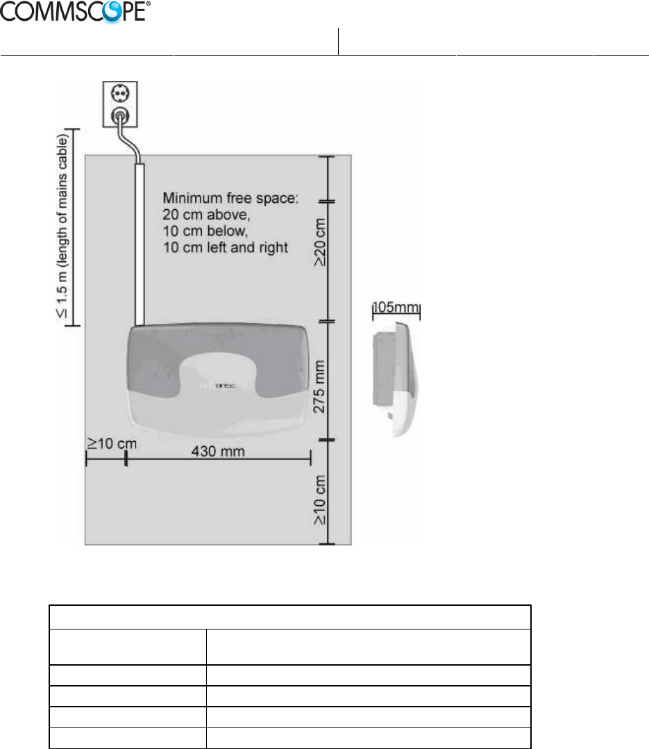
Make sure that the wall and wall anchors can stand the weight of the unit.
Positioning requirements
Mounting: Fastened with screws to wall (standard). Ceiling or pole
(optional)
Dimensions: 430 x 275 x 105 mm (W×H×D)
Minimum free space: 200 mm above, 100 mm below, 100 mm left and right.
Weight: < 7kg
Distance from mains outlet:
1.8 m (determined by the power cord)
4.3 Environmental conditions
OneBASE
™
fulfils the environmental conditions stated in IEC 60 721-3-3
“Classification of environmental conditions - Part 3: Classification of groups of
environmental parameters and their severities - Section 3: Stationary use at
weather protected locations”, classes 3K4/3Z2/3Z7/3B1/3C2/3S2/3M4.
A subset of the environmental requirements is shown in the following table.

Prepared.:
Mats Arnebjer
Released:
2012-10-09
Page:
14(34)
Approved:
Anders Norberg
Checked:
PW
Doc.no:
DOC001/DE14 Ver:
4
Company Confidential
Printed Copies are Uncontrolled
Environmental requirements (subset of IEC 60 721-3-3)
Ambient temperature: -5 to +45 °C
Relative humidity: <95%
Dust proof: Yes, no impact on the operation.
Heat dissipation: < 50W
Sealing class
(according to EN 60529)
IP 30 Node B Unit
IP 51 Power Supply
4.4 IP/Ethernet Transport
The transport interface (Iub) on the OneBASE
™
Node B is Ethernet over a twisted
pair cable connected to a RJ45-socket. The socket has a yellow LED for
transmission indication.
Make sure the site is equipped with a Local Area Network connection as close as
possible to the OneBASE
™
Node B.
The IP properties to be used must be configured during commissioning of the
OneBASE
™
Node B. See reference [commissioning-manual] and [office-data-
manual].
The type of cable to use is a CAT5 or CAT6 twisted pair cable with symmetrical
wiring and an impedance of 100 Ohm. Preferably use shielded cable. The pinning
follows the standard for a RJ-45 port.
4.5 Mains power
OneBASE
™
is delivered with a mains cable with an IEC 60320 C15 connector in
one end for connection to the AC/DC unit and either an open end or an AC Mains
plug in the other end.
The site should be equipped with an easily accessible earthed AC mains outlet or
an AC interconnect box with protective earth, as applicable, within range of the
OneBASE
™
Node B unit.
Prepared.:
Mats Arnebjer
Released:
2012-10-09
Page:
15(34)
Approved:
Anders Norberg
Checked:
PW
Doc.no:
DOC001/DE14 Ver:
4
Company Confidential
Printed Copies are Uncontrolled
The unit must always be connected to protective earth.
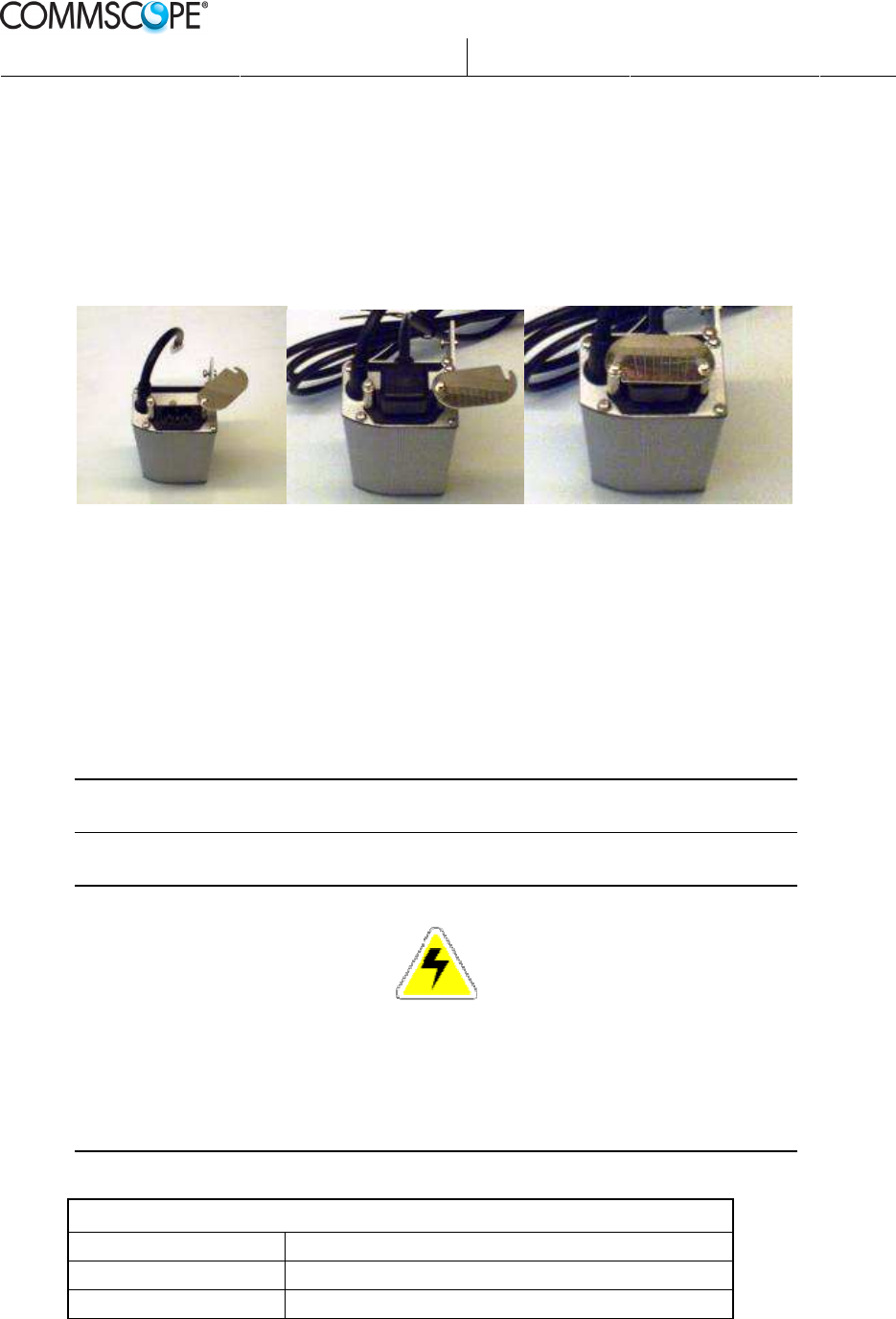
4.5.1 Permanent AC Connection
If permanent mains installation is required:
1. Connect the unit to an AC interconnection box, instead of an AC mains outlet.
2. Lock the AC cable to the AC/DC converter as described below.
To lock down the connector at the AC/DC end of the cable for a permanent
installation use the connector bracket.
• Open the bracket by loosening the screw closest to the output cable.
Swing the bracket open to allow for the connector to be inserted.
• Insert the connector into the AC/DC unit.
• Swing back the bracket and tighten the screws.
Make sure that approved circuit breakers for the AC mains and the cross sectional
areas of cables are selected in accordance with local laws and regulations.
Note: Always use the AC/DC converter delivered with the support unit.
No other converters are allowed.
DANGER
Improper mains power installation may cause fire or electrical shock.
Only a qualified and authorized electrician is permitted to
install or modify the electrical installation.
The OneBASE
™
Node B unit must always be connected to protective earth.
Power requirements
Supply voltage: 110/230 VAC ±10%, 50/60 Hz
Power consumption: < 50 W
Cable length: 1.8 m (supplied with OneBASE
™
)
Prepared.:
Mats Arnebjer
Released:
2012-10-09
Page:
16(34)
Approved:
Anders Norberg
Checked:
PW
Doc.no:
DOC001/DE14 Ver:
4
Company Confidential
Printed Copies are Uncontrolled
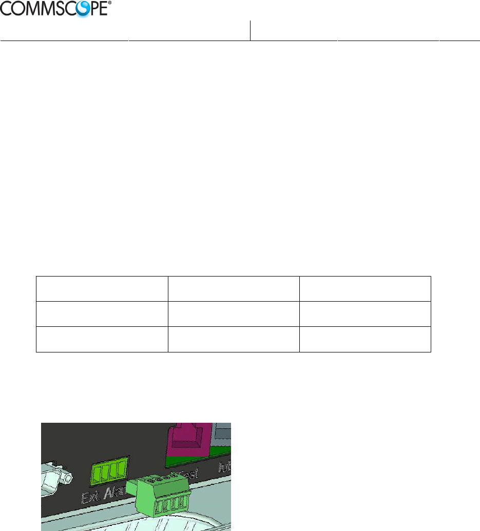
4.6 External alarms
OneBASE
™
is equipped with an alarm connector for connecting two external
alarms. The type of alarms used must be configured by setting the name, function,
and severity of the two alarms in the OneBASE
™
Node B Office Data. See
reference [commissioning-manual] and [office-data-manual]
By default the alarms are set to “Not used”.
The alarm circuits can be defined as normally open or normally closed and when
the alarm is activated an alarm notification is sent to NNM/OMC.
The alarm inputs are galvanic isolated.
External alarm trig points
Sensed impedance State Current/Voltage
<200 Ohm Closed 10 mA (typical)
> 2 kOhm Open 3.0 V (typical)
The supplied connector/plug is a 4-position terminal block connector (AMP
28513-4). Twisted pair cables should be used (2-wire or 4-wire). The wire ends
are inserted into the plug and fixed with screws.
4.7 External antennas
The OneBASE
™
Node B unit may be used with external antennas. Since the unit
includes duplex filters to provide receiver diversity, no external duplex filters are
needed.
The OneBASE
™
Node B unit is provided with two female QMA connectors.
Antenna cables with angled (90°) male plugs should be used.
The type of cables to use depends on antenna gain, distance, acceptable loss etc.
Refer to recommendations from antenna supplier.
Prepared.:
Mats Arnebjer
Released:
2012-10-09
Page:
17(34)
Approved:
Anders Norberg
Checked:
PW
Doc.no:
DOC001/DE14 Ver:
4
Company Confidential
Printed Copies are Uncontrolled
Note: Refer to instructions from the antenna supplier on how to install external
antennas, antenna cables, and antenna distribution systems.
CAUTION
It is the responsibility of the network provider to implement prevention measures to
avoid health hazards which may be associated to radiation from any external antenna
connected to the unit.
External antennas may require lighting protection and/or over voltage protection.
This is out of the scope of this manual.
4.8 Other external equipment
Other external equipment is for example booster, repeater, or antenna distribution
systems. Refer to instructions from the supplier of this equipment
Prepared.:
Mats Arnebjer
Released:
2012-10-09
Page:
18(34)
Approved:
Anders Norberg
Checked:
PW
Doc.no:
DOC001/DE14 Ver:
4
Company Confidential
Printed Copies are Uncontrolled
5 Installation
5.1 Prerequisites
Before beginning the installation of the OneBASE
™
Node B unit, make sure that
all materials are acquired, that is, the OneBASE
™
Node B unit with it’s mounting
material, cables, tools and screws.
Site preparation should preferably be done in advance according to the previous
chapter. However, the hardware installation may be done without transmission
available.
5.2 Precautions
CAUTION
Make a visual check of the safety of the site before starting any installation.
If any risks are foreseen, do not proceed.
Make sure that the installation conforms to relevant national installation rules.
5.3 Installation tools and material
The following tools and installation material are recommended. Other tools,
equipment, or installation details may be required due to local conditions.
• Support unit for wall mounting, and possibly optional mounting kit for ceiling
mounting.
• Screws and plugs for fitting the support unit to the wall (depending on type of
wall). The recommended diameter of screws is 6 mm.
• Screwdriver suitable for the selected mounting screws.
• Drilling machine and drills suitable for the selected mounting screws and type
of wall.
• Electrical Multi-meter, for checking the mains voltage.
• Earthed Mains plug to attach to cable end.
• Spirit level, for checking horizontal adjustment.
• Tools and material for running and/or fixing cables to wall or ceiling. For
example wire straps, cable clamps, and cable grooves.
• Padlock (optional) for locking the Node B to the support unit, and thereby to
the wall.
Prepared.:
Mats Arnebjer
Released:
2012-10-09
Page:
19(34)
Approved:
Anders Norberg
Checked:
PW
Doc.no:
DOC001/DE14 Ver:
4
Company Confidential
Printed Copies are Uncontrolled
5.4 Unpacking
Check the packaging for shipping damages on delivery. If there is any evidence of
damage, do not proceed.
Unpack the equipment and make sure everything is included in the delivery:
• Node B unit, including:
- Internal antenna (optional, separately packed)
- Cover (separately packed)
• Support unit (mounting frame), including:
- AC/DC converter (normally fitted to the Support unit)
- Power cord, 1.8 m
• Pole mounting kit (optional)
• Ceiling mounting kit (optional)
The Node B unit and the AC/DC converter is marked with a serial number for
identification.
5.4.1 Installing the internal antenna (optional)
1. Place the antenna in the grove one the Node B unit so that the holes lines up.
2. Fasten the antenna onto the Node B unit with the supplied screws, one in the
upper left corner and one in the lower right of the antenna.
3. Push the male QMA plugs (angled 90°) to the female QMA connectors
Tx/RxA and RxB on the left side of the OneBASE™ panel.
Installing internal antenna
Prepared.:
Mats Arnebjer
Released:
2012-10-09
Page:
20(34)
Approved:
Anders Norberg
Checked:
PW
Doc.no:
DOC001/DE14 Ver:
4
Company Confidential
Printed Copies are Uncontrolled
5.5 Mounting
Always use the supplied support unit to mount the OneBASE
™
Node B. To mount
the unit to a wall, see Wall mounting below.
Note: Make sure that the requirements on positioning the OneBASE
™
Node B unit
are fulfilled. See
Positioning
on page 12 for details.
Mounting to a ceiling or on a pole requires an optional mounting kit to be ordered
separately. See Pole or ceiling mounting on page 27.
5.5.1 Wall mounting
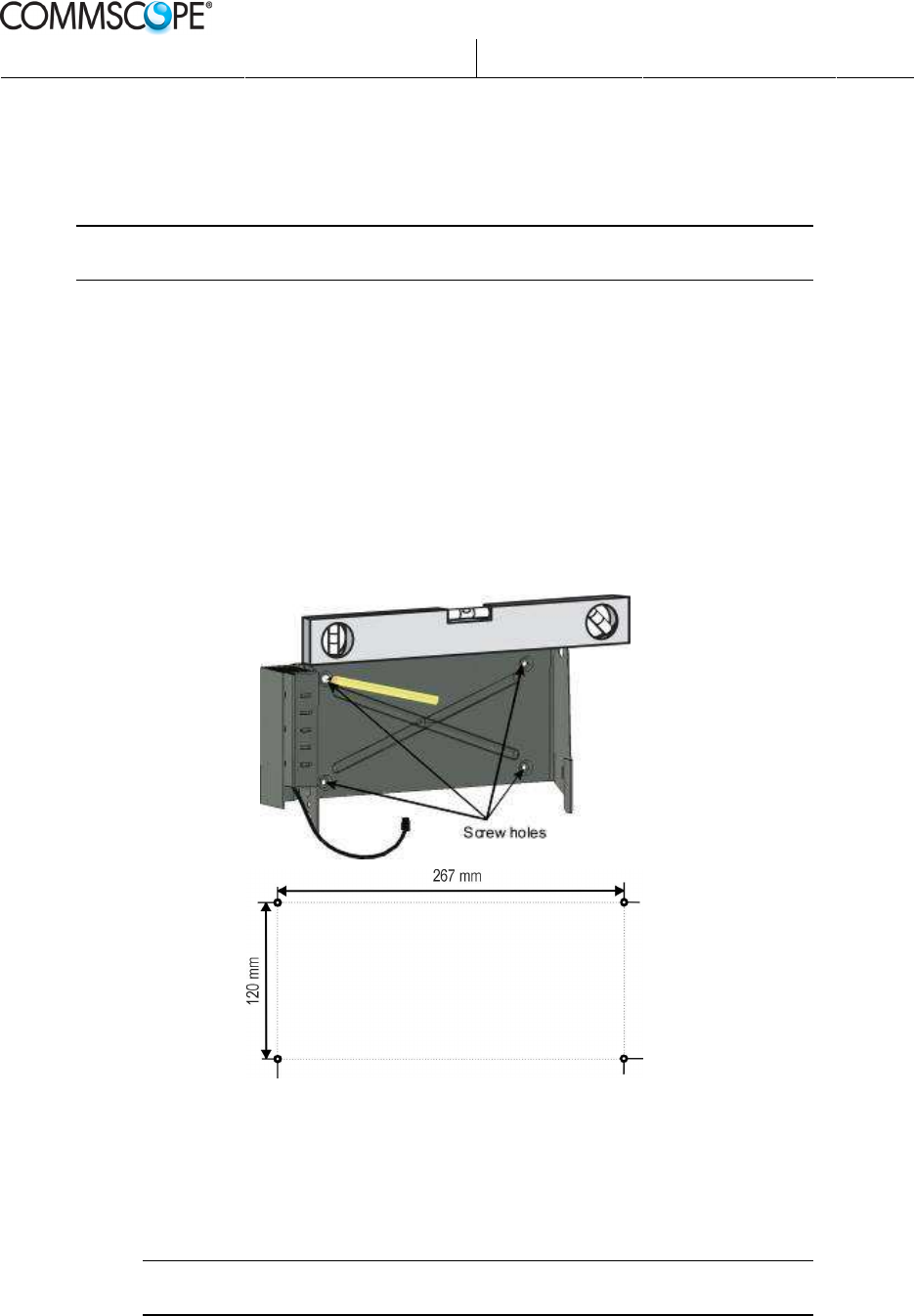
5.5.1.1 Fitting the support unit
1) Use the support unit to mark up the position of the screw holes on the wall.
Use a spirit level to make sure that the holes are level.
2) Remove the support unit and drill holes suitable for the applicable wall
material. The recommended diameter of the screws to use is 6 mm.
Plugs should be used for concrete, brick, and plaster walls. Follow the
instructions by the supplier of plugs.
Note: Make sure to consider any specific local conditions and regulations to
securely fix the OneBASE
™
to the wall.
Prepared.:
Mats Arnebjer
Released:
2012-10-09
Page:
21(34)
Approved:
Anders Norberg
Checked:
PW
Doc.no:
DOC001/DE14 Ver:
4
Company Confidential
Printed Copies are Uncontrolled
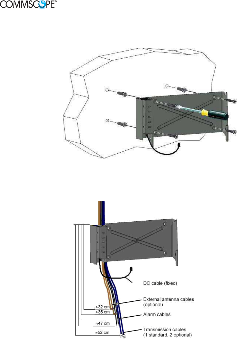
3) Fasten the support unit onto the wall with screws. The AC/DC converter is
already mounted on the left side of the support unit.
Fitting the support unit
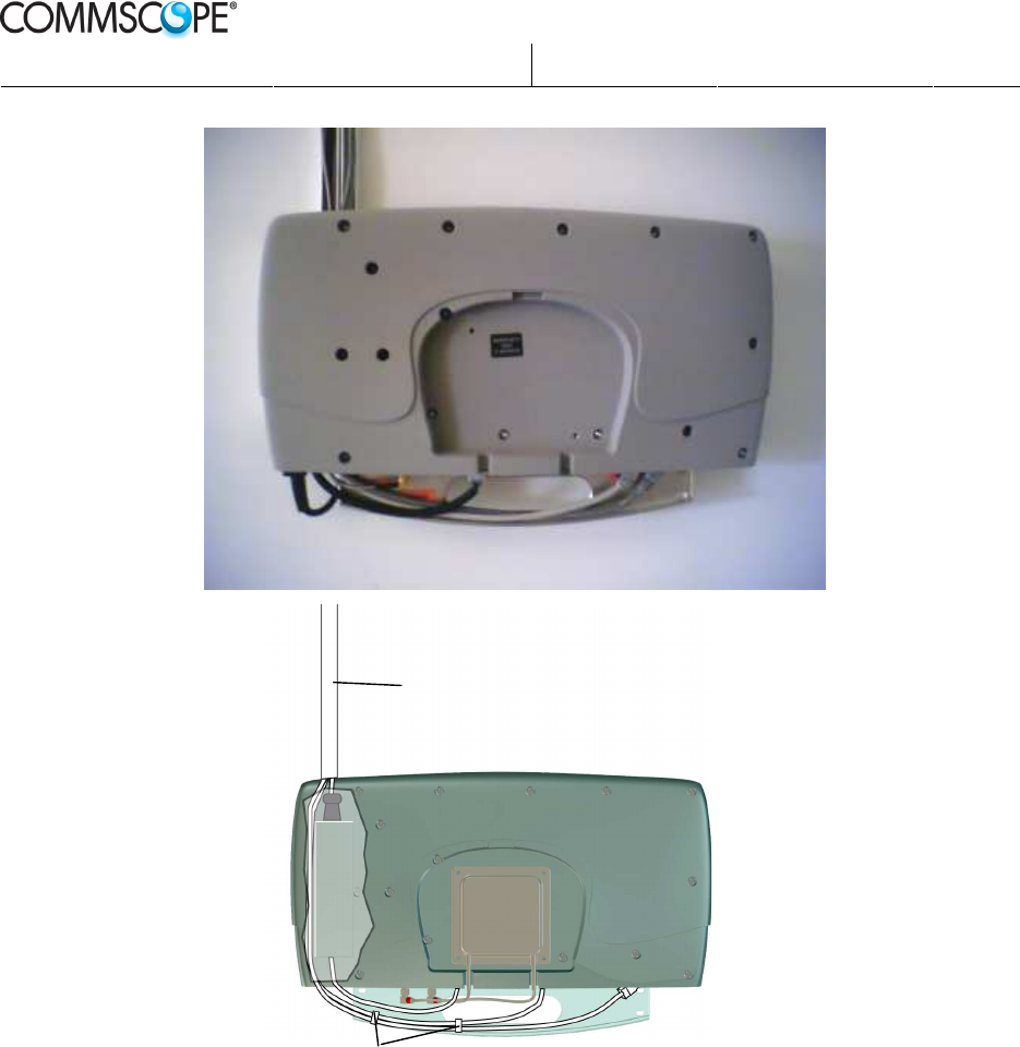
4) Run all external cables inside the space under the clamp along the right
side of the AC/DC unit. Make the cables only as long as needed, to avoid
excess cabling at the Node B unit. Excess cabling should be hidden at the
other end, on a cable ladder under the ceiling or similar.
Running cables
Prepared.:
Mats Arnebjer
Released:
2012-10-09
Page:
22(34)
Approved:
Anders Norberg
Checked:
PW
Doc.no:
DOC001/DE14 Ver:
4
Company Confidential
Printed Copies are Uncontrolled
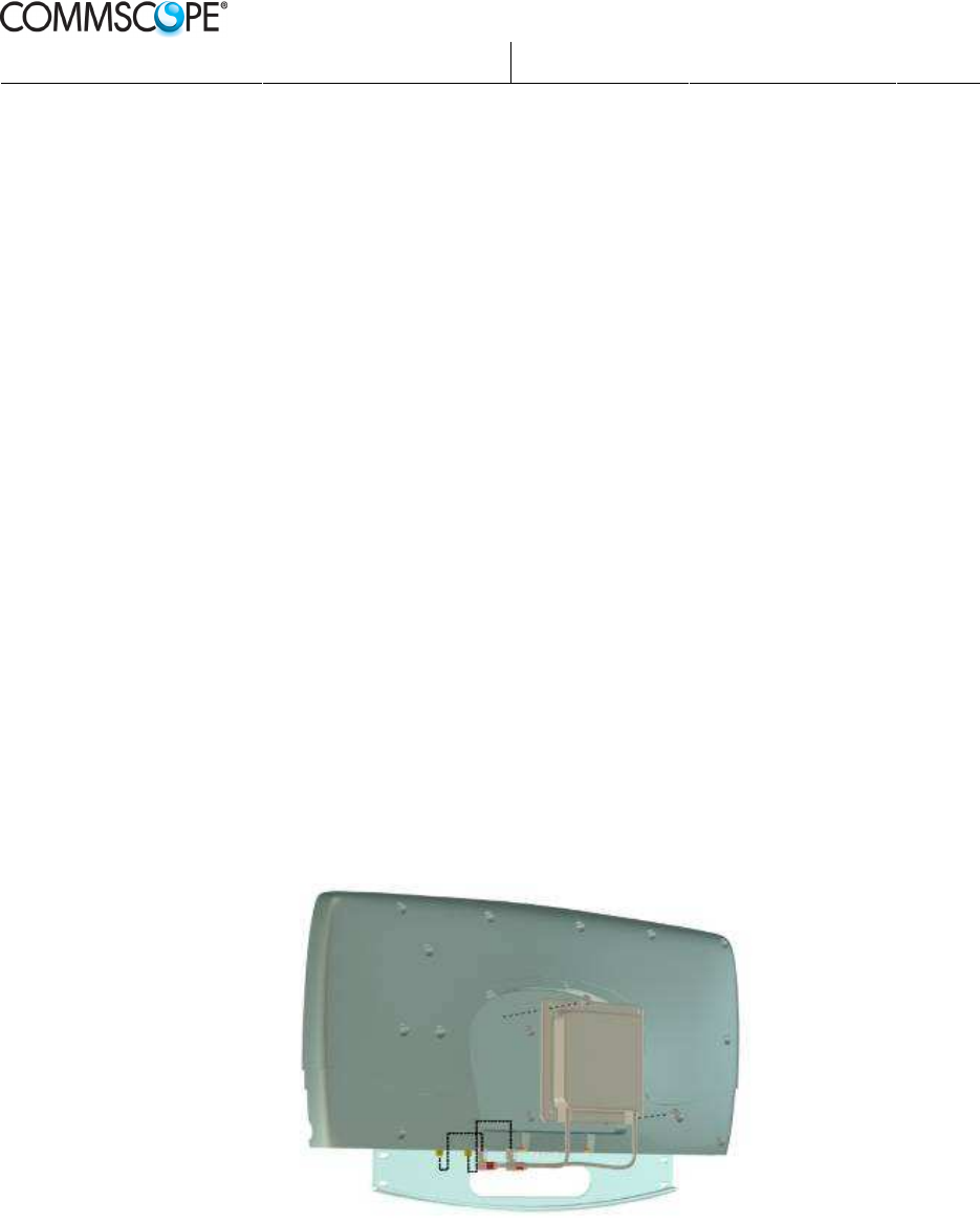
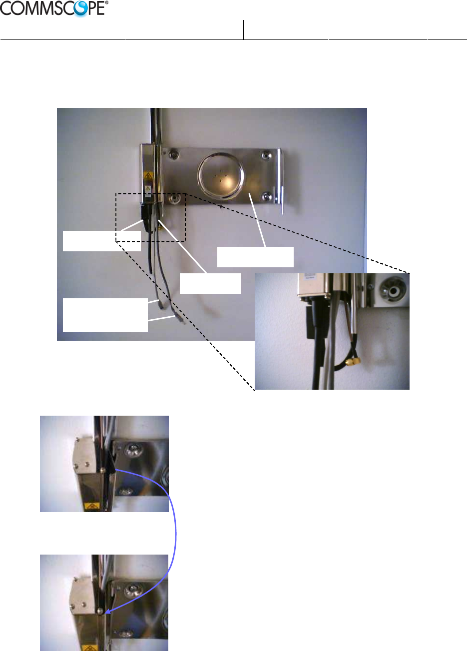
5) Connect the plug of the supplied AC cable to the bottom of the AC/DC
converter. Make sure that the plug is angled to the right.
Support Unit
RF Cable
Power Cable
Transmission
Cables
Support Unit
RF Cable
Power Cable
Transmission
Cables
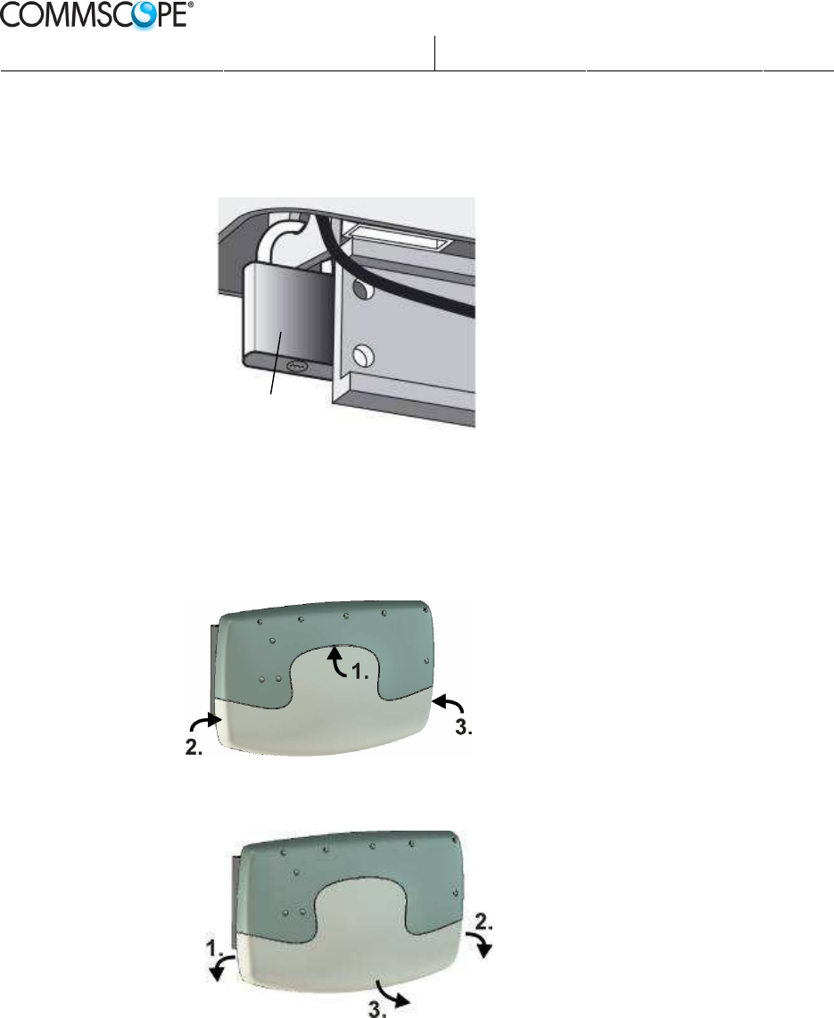
The cable
cover is
closed
before the
Pico Unit is
mounted
Prepared.:
Mats Arnebjer
Released:
2012-10-09
Page:
23(34)
Approved:
Anders Norberg
Checked:
PW
Doc.no:
DOC001/DE14 Ver:
4
Company Confidential
Printed Copies are Uncontrolled
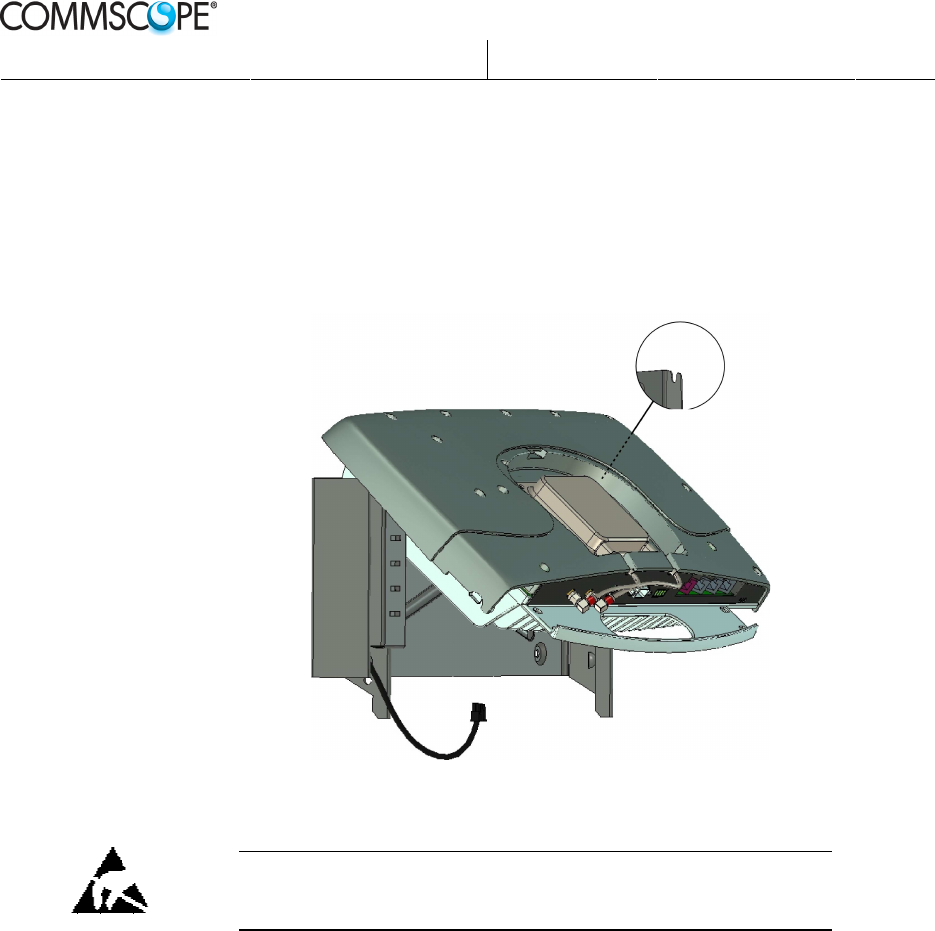
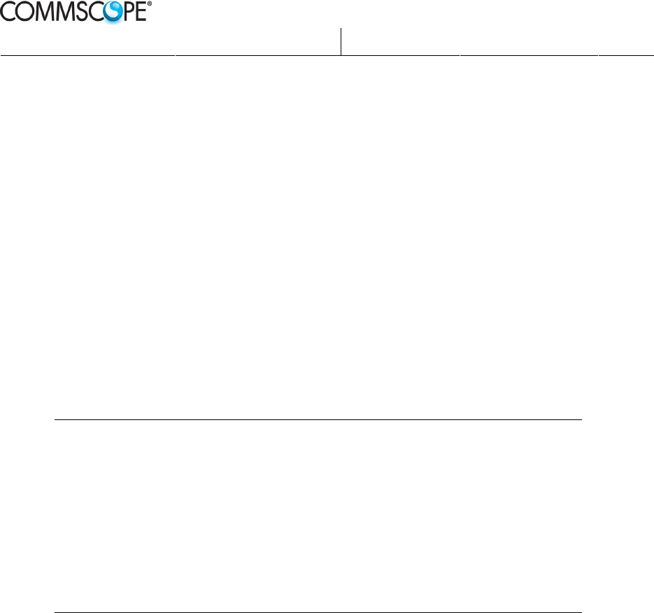
5.5.1.2 Fitting the Node B unit
1) Make sure the cable cover is closed before hanging the Node B unit onto the
support unit.
2) Hang the Node B unit onto the hinges of the support unit.
3) Gently fold the unit down and snap it firmly into position. To remove the unit
push the levers towards the center while lifting the handle.
Fitting the OneBASE
™
Node B unit on the support unit
5.5.1.3 Connecting the cables
Note: Make sure the Node B unit is connected to earth by
connecting the power cables before connecting any other
cables.
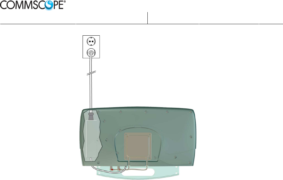
1) Connect the AC mains cable from the AC/DC converter of the
OneBASE™ support unit to a mains outlet (unless the mains cable is
permanently connected).
2) Connect the DC power cable from the AC/DC converter to the DC-Power
input on the OneBASE™ panel.
Prepared.:
Mats Arnebjer
Released:
2012-10-09
Page:
24(34)
Approved:
Anders Norberg
Checked:
PW
Doc.no:
DOC001/DE14 Ver:
4
Company Confidential
Printed Copies are Uncontrolled
Power cables of the OneBASE
™
The Node B unit is now earthed. Then connect the remaining cables from left to
right:
3) Connecting the antenna:
a. If internal antenna is used, the connectors may already fitted on
delivery. Otherwise see 5.4.1
b. If external antenna is used, push the male QMA plugs (angled 90°)
to the female QMA connectors Tx/RxA and RxB on the left side of
the OneBASE™ panel.
4) Connect the external alarm cable to the Ext-Alarm connector on the
OneBASE™ panel. The connector is a 4-position terminal block where the
alarm wires are screwed to a plug, which is then fitted to the connector.
See External alarms on page 16 for more information.
5) IP transmission:
Connect the LAN cable to the Ethernet connector.
6) LMT can be connected to the LAN.
7) Check that all cables are correctly and securely connected.
8) Pull back excess cabling and strap the cables close to the connectors.
Prepared.:
Mats Arnebjer
Released:
2012-10-09
Page:
25(34)
Approved:
Anders Norberg
Checked:
PW
Doc.no:
DOC001/DE14 Ver:
4
Company Confidential
Printed Copies are Uncontrolled
Fixing cables
9) Fix the cables to the wall and/or to the ceiling by using wire clamps or
cable grooves, as applicable.
Wire straps
Cable groover
Prepared.:
Mats Arnebjer
Released:
2012-10-09
Page:
26(34)
Approved:
Anders Norberg
Checked:
PW
Doc.no:
DOC001/DE14 Ver:
4
Company Confidential
Printed Copies are Uncontrolled
5.5.1.4 Fitting a padlock
Fit a padlock (not supplied), if required, to lock the Node B unit to the support
unit.
Fitting a padlock
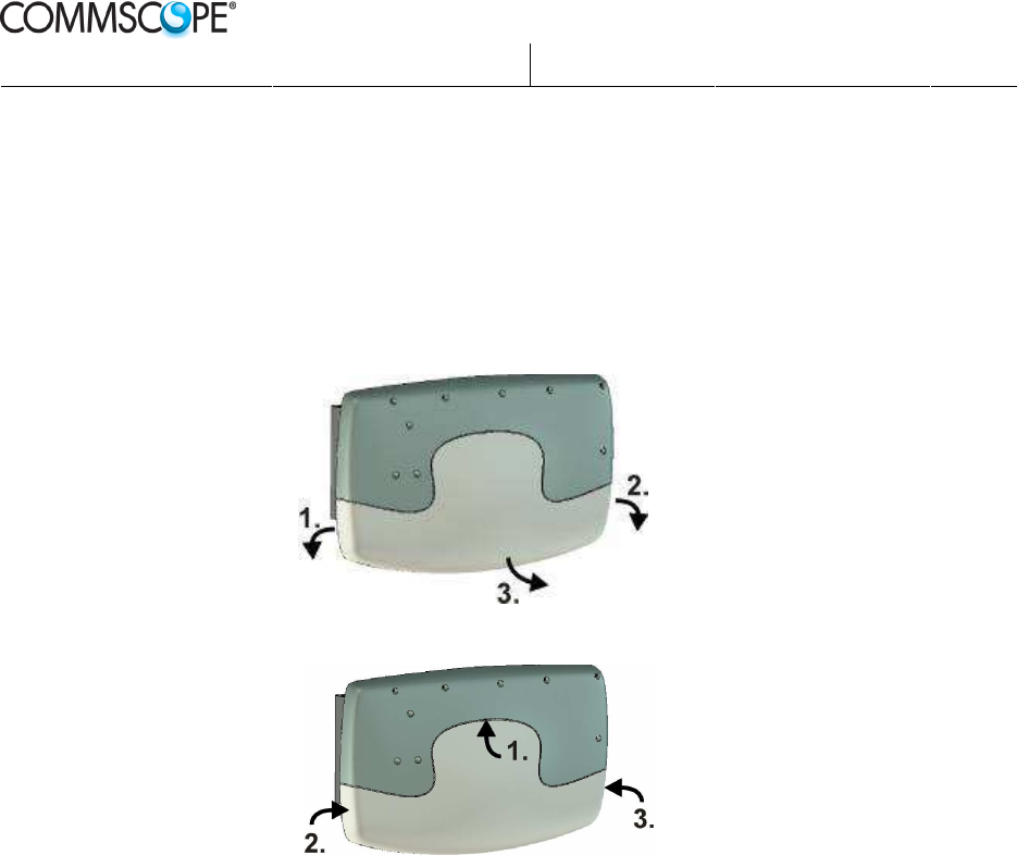
5.5.1.5 Fitting the cover
1) Fit the cover by first fitting the tab on the top of the cover into the
corresponding slot on the Node B unit, and then firmly press the left and right
edges until they click into position.
Removing cover
Fitting cover
2) Remove the cover by firmly loosen the left and right edges of the cover from
the Node B unit and then lift the cover upwards.
The cover can be left off if commissioning is done as the next step after the
hardware installation.
Padlock
Prepared.:
Mats Arnebjer
Released:
2012-10-09
Page:
27(34)
Approved:
Anders Norberg
Checked:
PW
Doc.no:
DOC001/DE14 Ver:
4
Company Confidential
Printed Copies are Uncontrolled
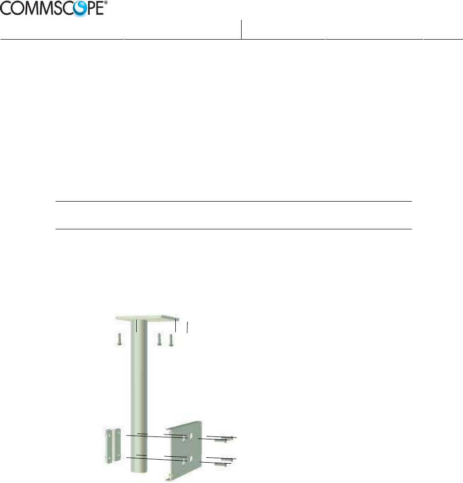
5.5.2 Pole or ceiling mounting
To mount the OneBASE
™
to the ceiling or on a flat surface, a pole with a
mounting plate is available as an option. The mounting plate can also be used
separately to mount the OneBASE
™
to an existing pole.
1) Use the pole of the ceiling mounting kit to mark up the position of the screw
holes on the horizontal surface.
2) Drill holes suitable for the applicable surface material. The recommended
diameter of the screws to use is 6 mm. Plugs should be used for concrete,
brick, and plaster surfaces. Follow the instructions by the supplier of plugs.
Note: Make sure to consider any specific local conditions and regulations to
securely fix the OneBASE
™
.
3) Fasten the pole into the ceiling or onto the flat horizontal surface with screws.
4) Clamp the mounting plate onto the pole using the four supplied M6 screws.
Before tightening the screws, make sure that the mounting plate is positioned
in the correct direction considering any internal antenna in the OneBASE™
Node B.
Pole mounting
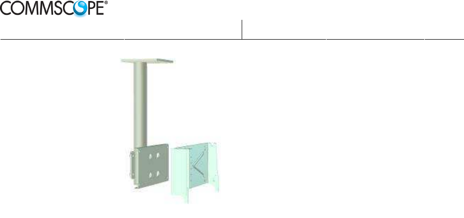
5) Fit the support unit onto the pole with the four supplied M6 screws.
Prepared.:
Mats Arnebjer
Released:
2012-10-09
Page:
28(34)
Approved:
Anders Norberg
Checked:
PW
Doc.no:
DOC001/DE14 Ver:
4
Company Confidential
Printed Copies are Uncontrolled
Fitting the support unit onto the pole
6) Then run all cables and fit the OneBASE™ Node B as described in step 4)
on page 21 and onwards in the section Wall mounting.
Prepared.:
Mats Arnebjer
Released:
2012-10-09
Page:
29(34)
Approved:
Anders Norberg
Checked:
PW
Doc.no:
DOC001/DE14 Ver:
4
Company Confidential
Printed Copies are Uncontrolled
5.6 Replacement of units
Faulty OneBASE
™
Node B units are not to be repaired in the field. However,
some field replaceable parts may be changed on site. Note that other articles not
listed below may be available. Contact your CommScope representative for a
complete article list and ordering information.
• OneBASE
™
Node B unit
• Internal antenna, including antenna cables
• Cover
• AC/DC converter
See the respective sub-sections below for replacement instructions.
Note: The casing of the OneBASE
™
Node B unit may on no occasion be opened.
There are no parts inside which can be repaired or replaced in field; Opening
the unit may destroy the calibration of the unit, in which case it has be sent
back to CommScope for control and recalibration.
In case the sealing has been broken CommScope voids the product warranty
and assumes no responsibility of the safety or performance.
5.6.1 Replacing OneBASE
™
Node B unit
5.6.1.1 Disconnecting
Before disconnecting any OneBASE
™
in operation, make sure that the O&M
staffs is informed.
1. Disconnect the mains power cable.
2. Remove the cover.
3. Remove any padlock.
4. Disconnect all cables from right to left.
5. If an internal antenna is fitted, remove it as described in “Replacing internal
antenna” on page 30.
Prepared.:
Mats Arnebjer
Released:
2012-10-09
Page:
30(34)
Approved:
Anders Norberg
Checked:
PW
Doc.no:
DOC001/DE14 Ver:
4
Company Confidential
Printed Copies are Uncontrolled
5.6.1.2 Dismounting
1. Loosen the unit from the support unit by pushing the levers on the lower left
and right sides towards the centre while lifting the handle.
Removing the OneBASE
™
Node B unit from the support unit
2. Gently lift the unit off the hinges of the support unit.
Then follow the Fitting the Node B unit at page 5.5.1.2 to install a replacement
unit.
If any internal antenna is to be re-fitted, follow the instructions below.
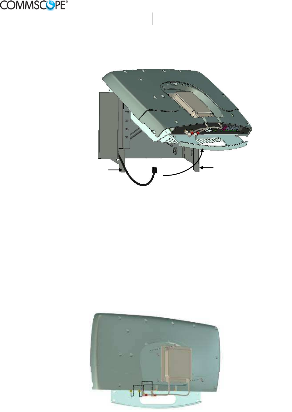
5.6.2 Replacing internal antenna
4. Remove the cover by sliding it downwards.
5. Unplug the QMA connectors fitted to the panel (Tx/RxA and RxB) by holding
on to the ring of the connector and pull outwards.
6. Loosen the two screws that hold the antenna to the OneBASE
™
Node B unit
and remove the antenna.
Replacing internal antenna
2. Lift handle
1. Push
Prepared.:
Mats Arnebjer
Released:
2012-10-09
Page:
31(34)
Approved:
Anders Norberg
Checked:
PW
Doc.no:
DOC001/DE14 Ver:
4
Company Confidential
Printed Copies are Uncontrolled
7. Fit a new antenna by reversing the above steps.
5.6.3 Replacing cover
1. Remove the cover by firmly loosening the left and right bottom edges, and
then lifting the cover upwards.
2. Fit a new cover by first fitting the top tab and then pressing firmly on the left
and right edges until they click into position.
Removing cover
Fitting cover
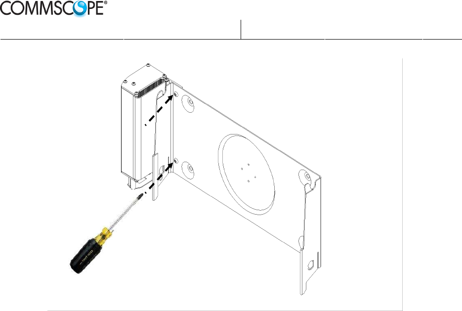
5.6.4 Replacing AC/DC converter
1. Remove the Node B unit as described in Replacing OneBASE™ Node B unit
on page 29.
2. Remove the AC/DC converter from the support unit by removing the two
screws that holds the AC/DC converter. A T20 torx driver is needed.
Prepared.:
Mats Arnebjer
Released:
2012-10-09
Page:
32(34)
Approved:
Anders Norberg
Checked:
PW
Doc.no:
DOC001/DE14 Ver:
4
Company Confidential
Printed Copies are Uncontrolled
Removing the AC/DC converter
3. Fit a new AC/DC converter by reversing the above steps.
Prepared.:
Mats Arnebjer
Released:
2012-10-09
Page:
33(34)
Approved:
Anders Norberg
Checked:
PW
Doc.no:
DOC001/DE14 Ver:
4
Company Confidential
Printed Copies are Uncontrolled
5.7 Handling of faulty units and replacement units
5.7.1 Disposal
Dispose of defective and/or broken components or units according to local
regulations, or return to the supplier, according to warranty or service agreements.
5.7.2 Packing requirements
Always use the original packaging. If this is not available, use enough protective
material to avoid transport damages.
See Unpacking on page 19 for information on original packaging.
5.7.3 Transport and storage requirements
The packed equipment must be stacked with care and properly secured to prevent
damage during transportation and storage.
The following environmental conditions must be followed during storage and
transportation:
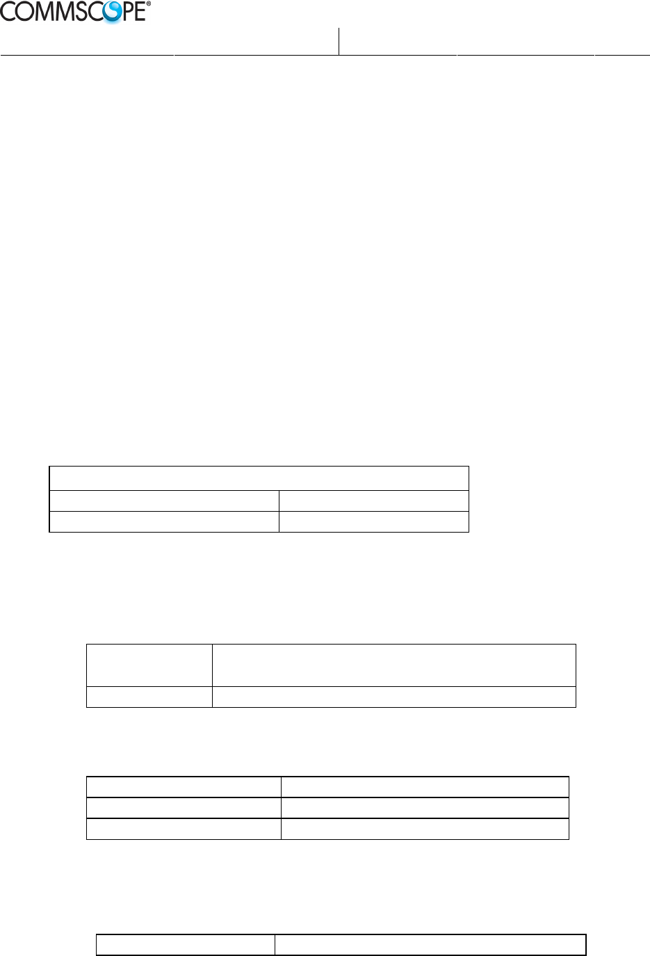
Environmental conditions during storage and transportation
Temperature: –25 to +70 ºC
Relative humidity: <95%
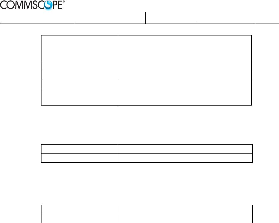
6 Technical data
6.1 Power supply
Supply voltage Single phase 110/230 VAC ±10%, 50/60 Hz
Withstands 20 ms interruption of AC input. @ 230 V
Power consumption < 50 W
6.2 Internal antenna (option)
Antenna gain 6 dBi
Polarization Dual Slant ±45°
Half Power Beam width 65°
6.3 Environmental data
Standards compliance IEC 60 721-3-3 “Classification of environmental
Prepared.:
Mats Arnebjer
Released:
2012-10-09
Page:
34(34)
Approved:
Anders Norberg
Checked:
PW
Doc.no:
DOC001/DE14 Ver:
4
Company Confidential
Printed Copies are Uncontrolled
conditions - Part 3: Classification of groups of
environmental parameters and their severities - Section 3:
Stationary use at weather protected locations”, classes
3K3/3Z2/3Z4/3Z7/3B1/3C2/3S2/3M1.
Operating temperature -5 to +45
o
C
Storage/transport temperature –25 to +70
o
C
Relative humidity <95%
Sealing class (according to
EN60529)
IP 30 Node B unit
IP 51 for AC/DC unit
6.4 Physical data
Mechanical dimensions (mm) 275 (H) x 430 (W) x 105 (D)
Weight 7 kg, incl. AC/DC and internal antenna
6.5 Safety
Product safety EN60950
Vandalism proof TORX screws. Possible to lock with padlock