Anritsu 6DXRA775UA Marine Radar RA775UA User Manual 0 TITLE
Anritsu Corporation Marine Radar RA775UA 0 TITLE
UserManual.wiki
>
Anritsu
>
6DXRA775UA User Manual
Users Manual
Navigation menu
Upload a User Manual
Namespaces
Wiki Guide
HTML
PDF
Info
Views
User Manual
Discussion / Help
Navigation


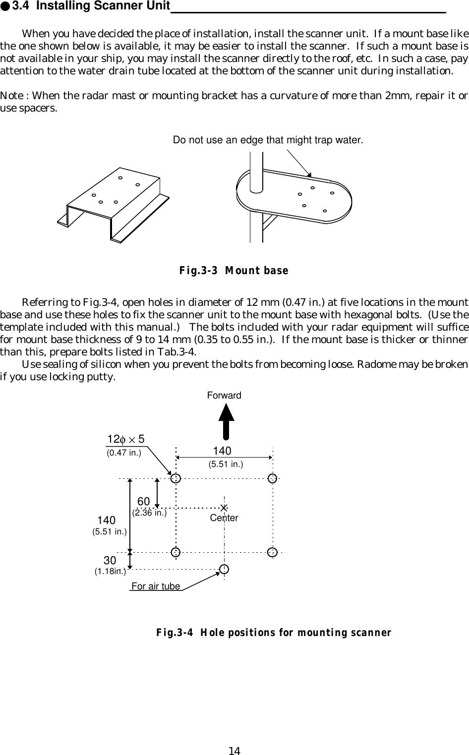
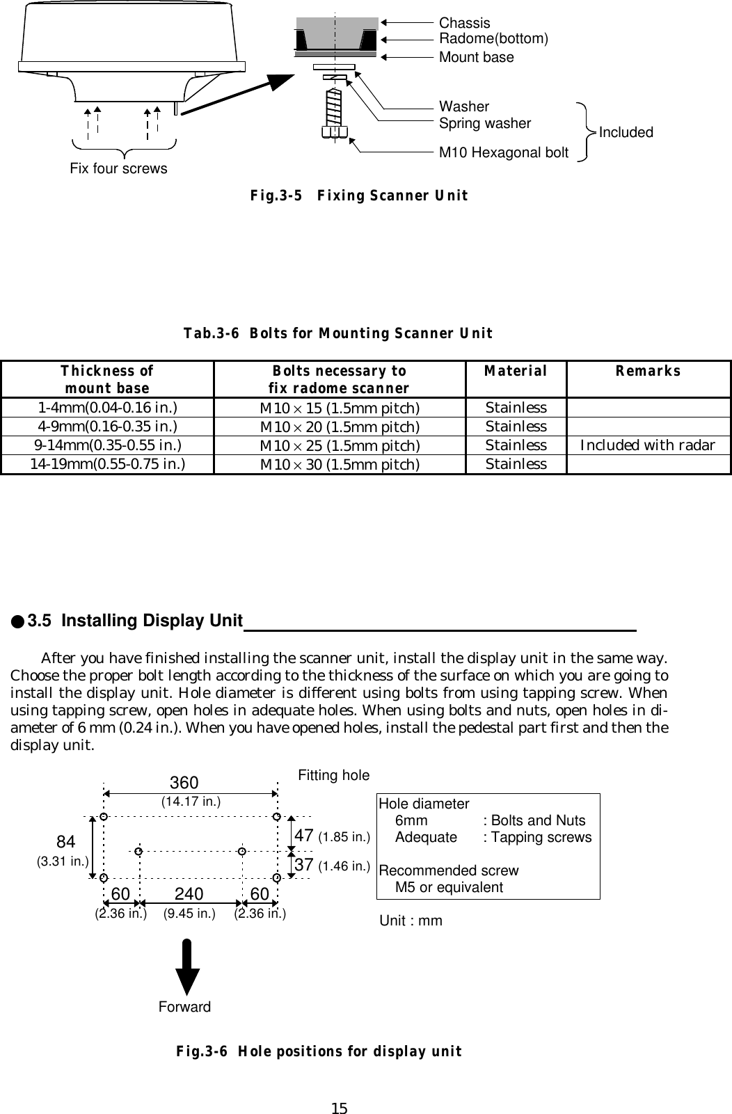
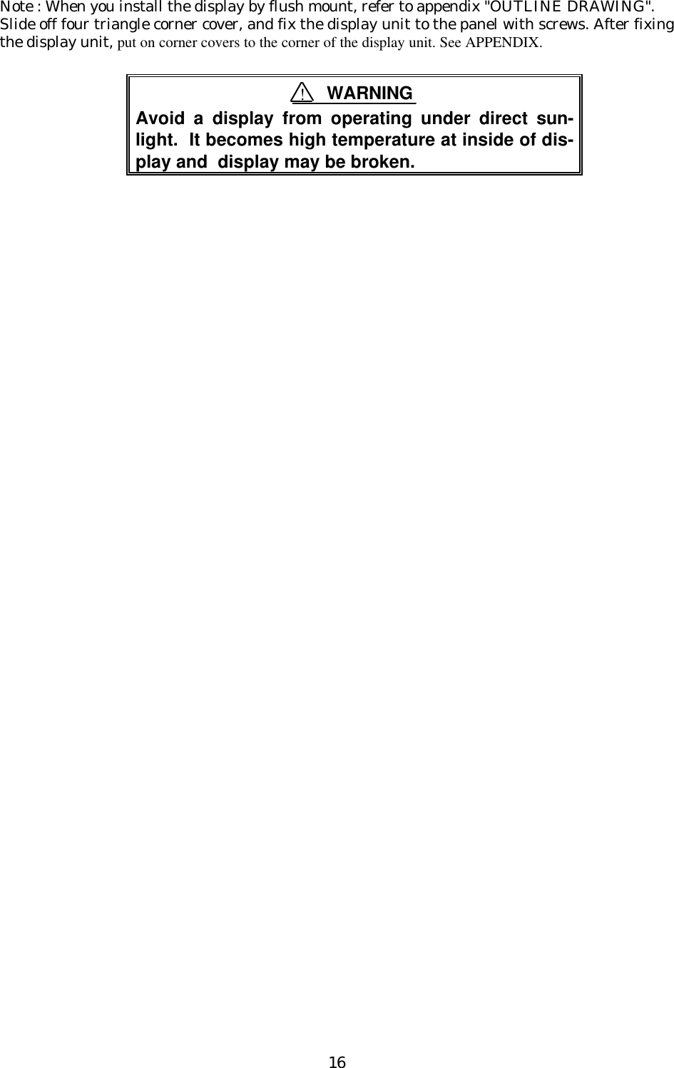
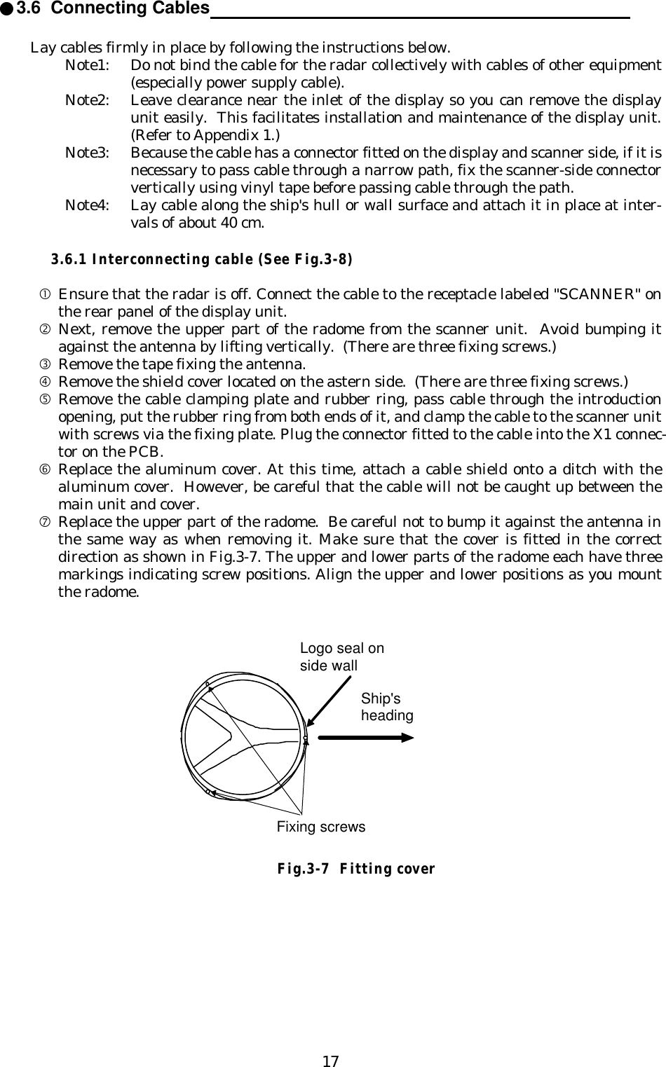
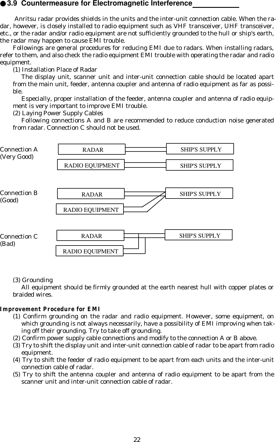
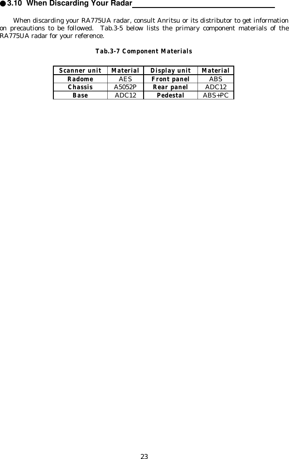
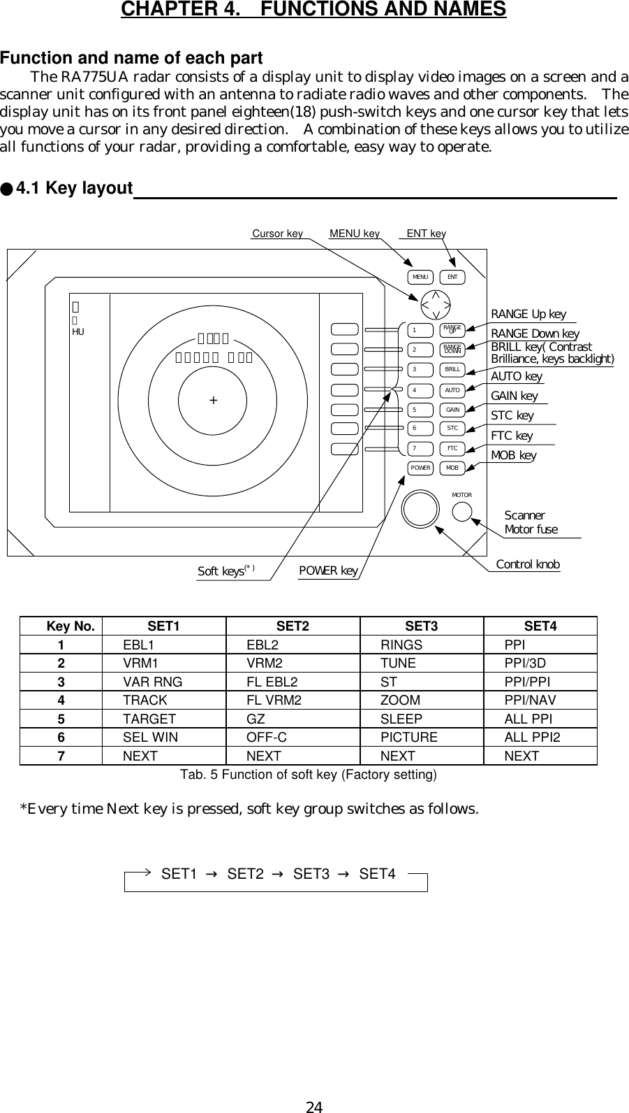
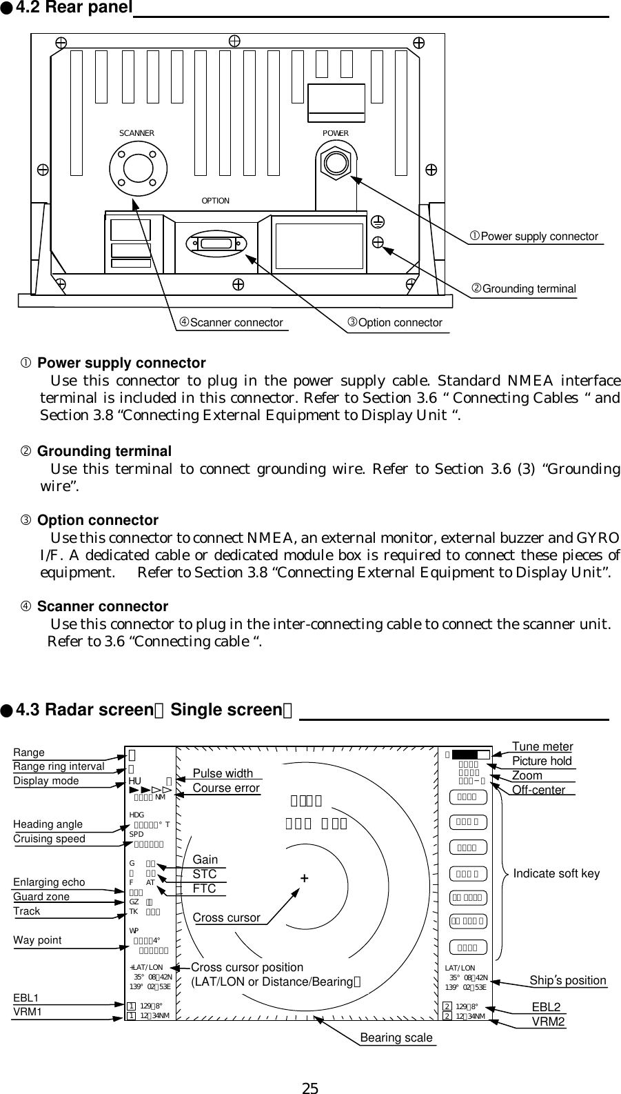
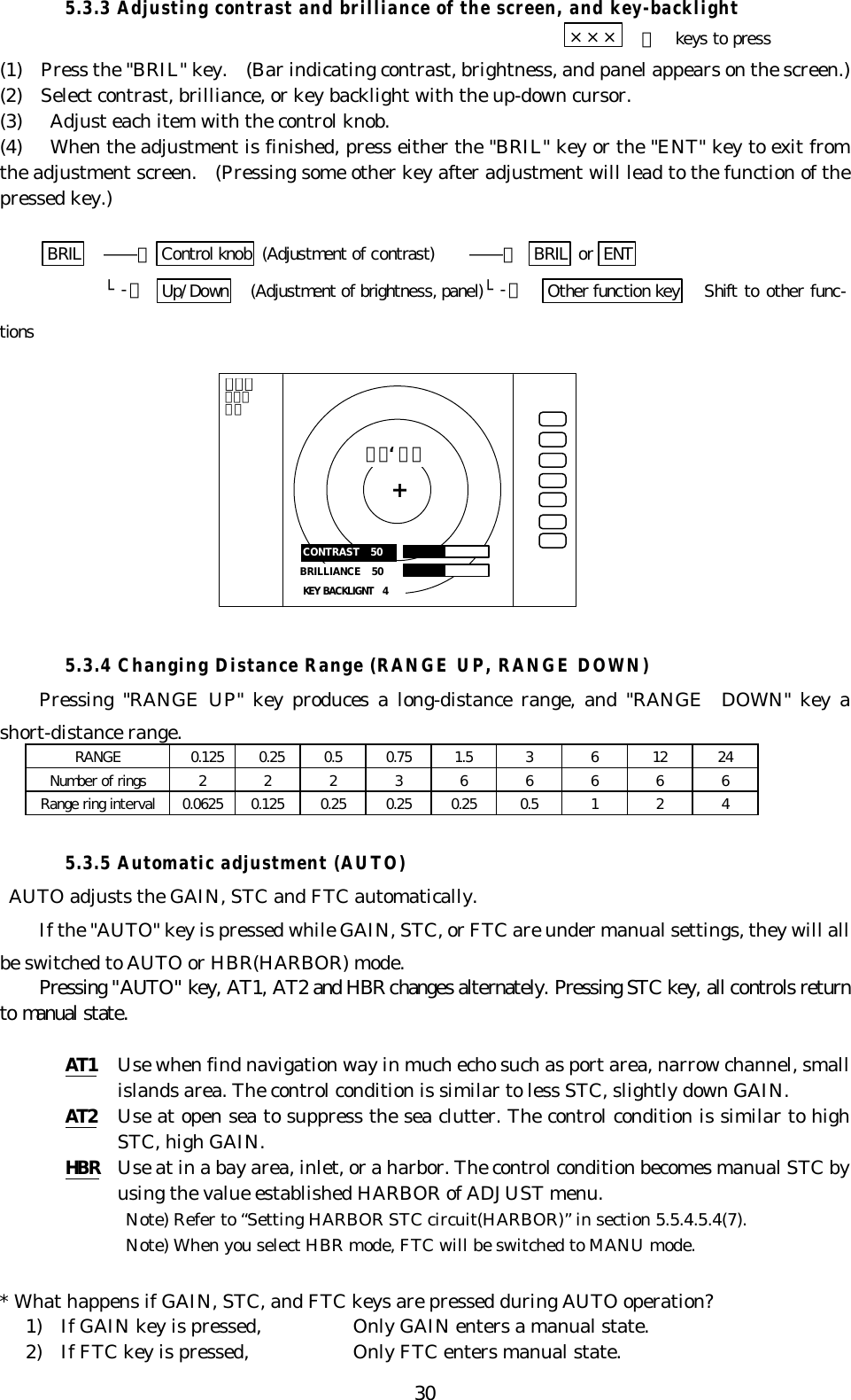
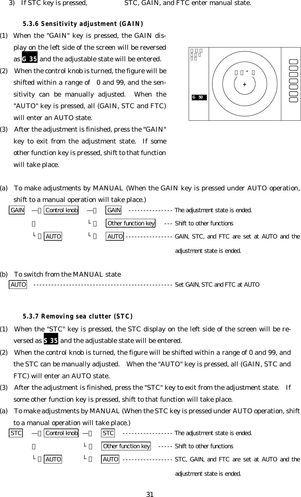
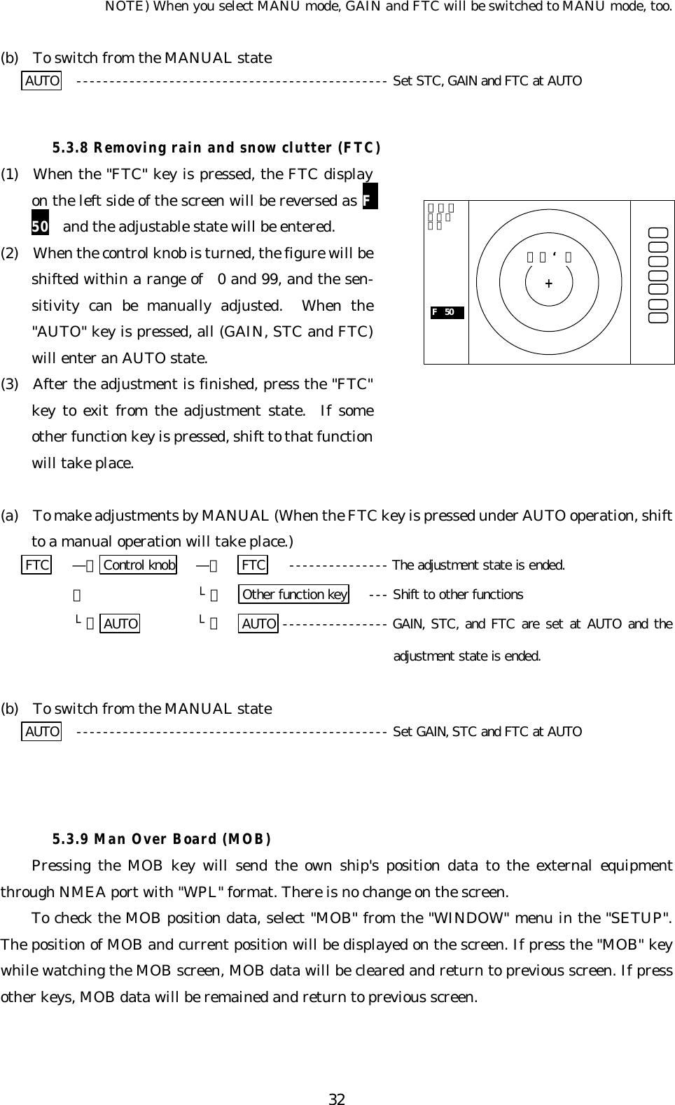
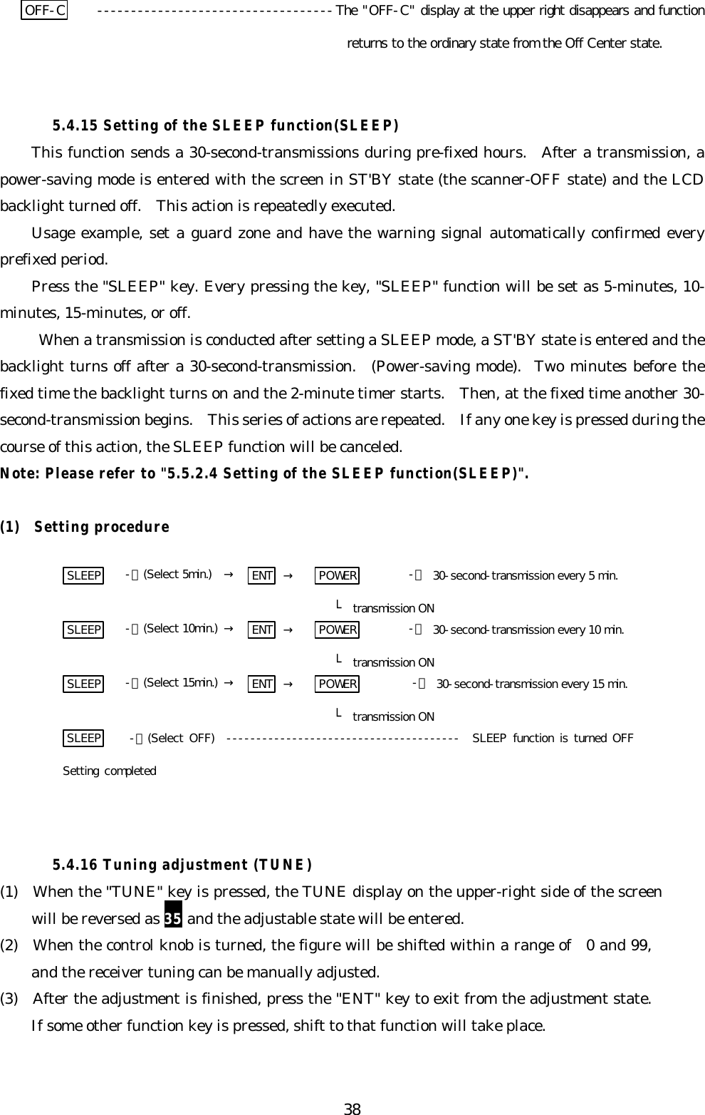
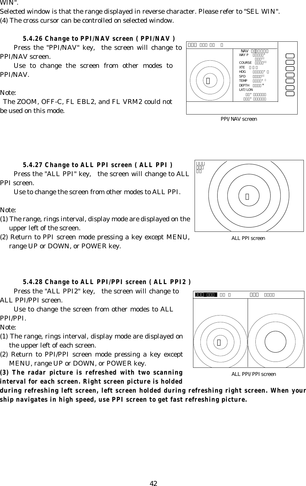
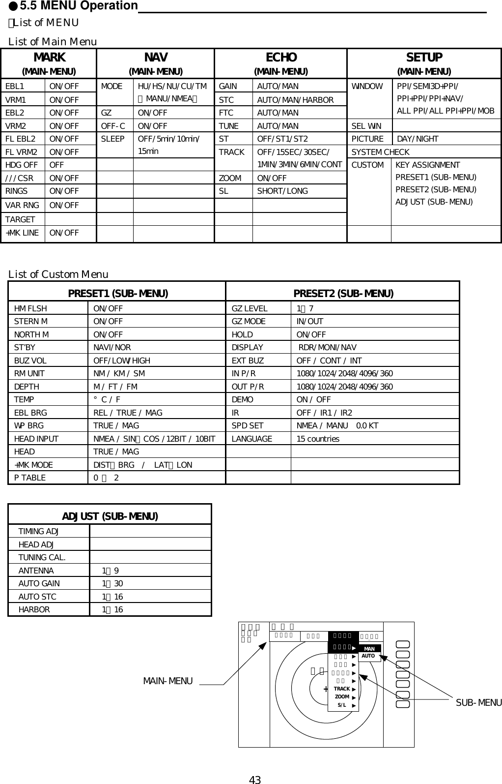
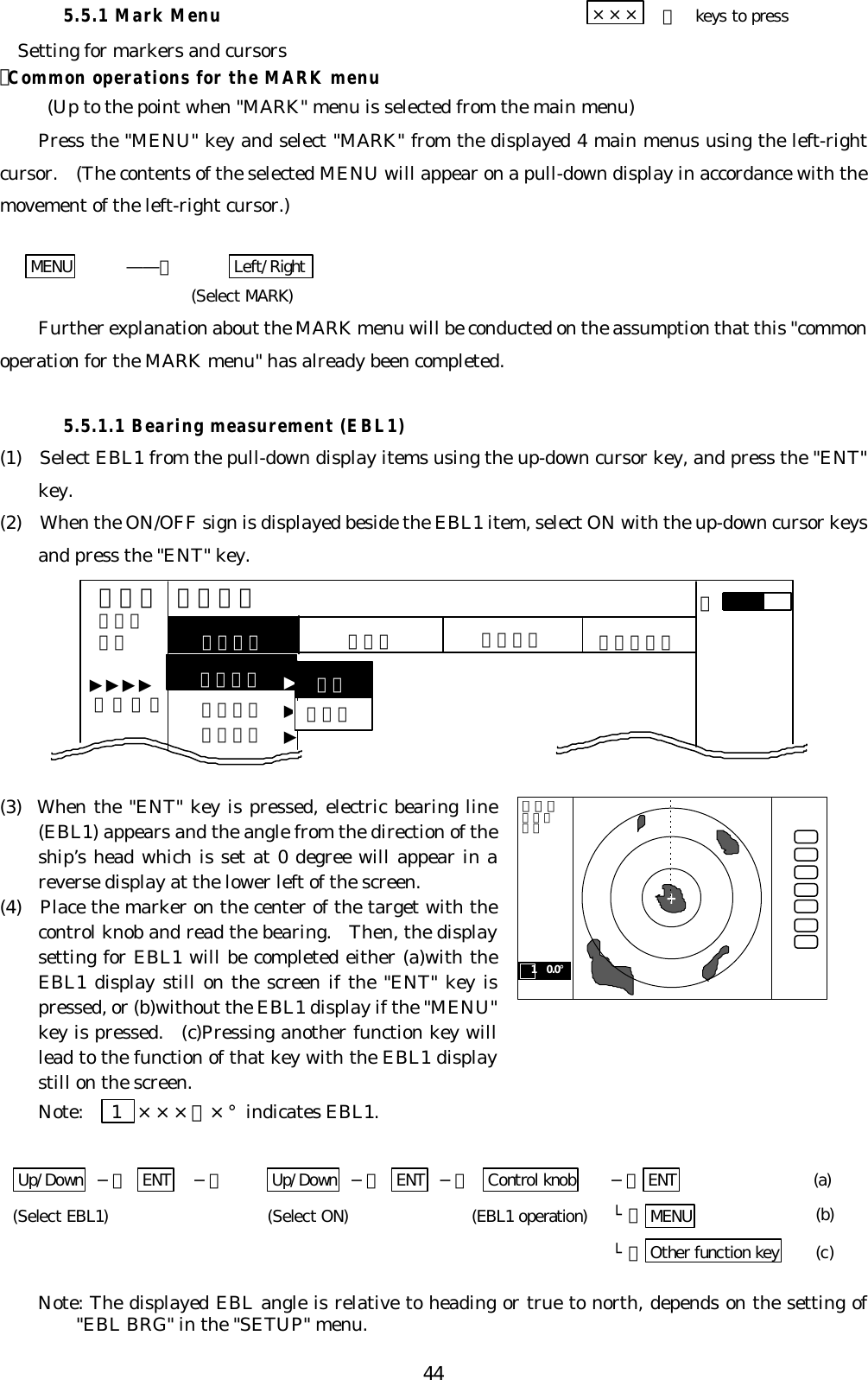
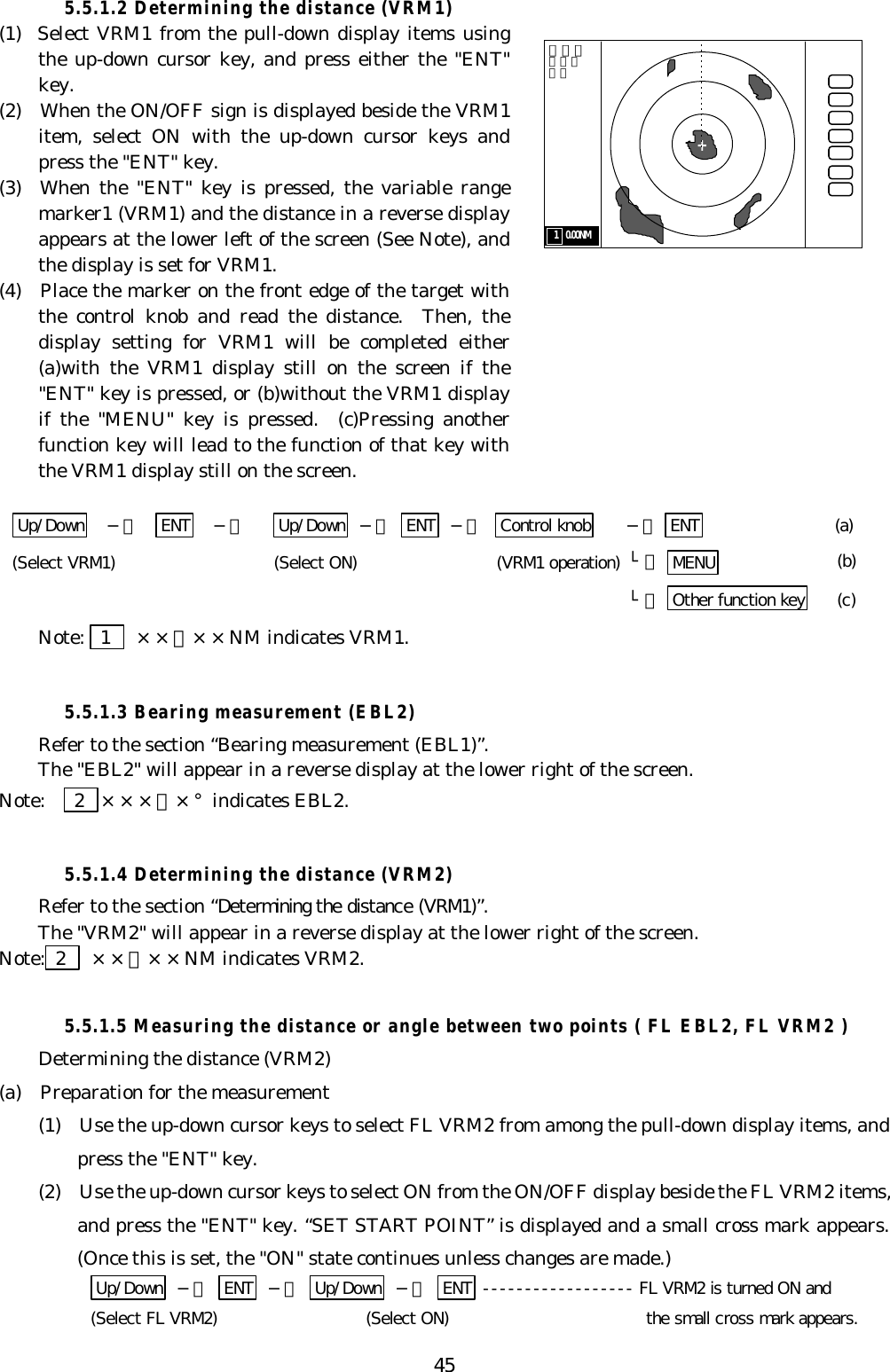
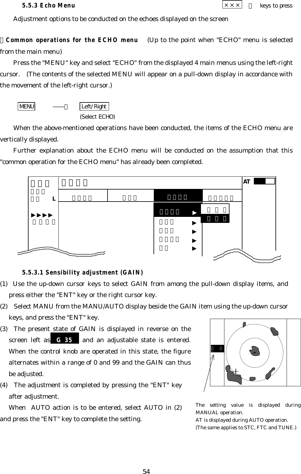
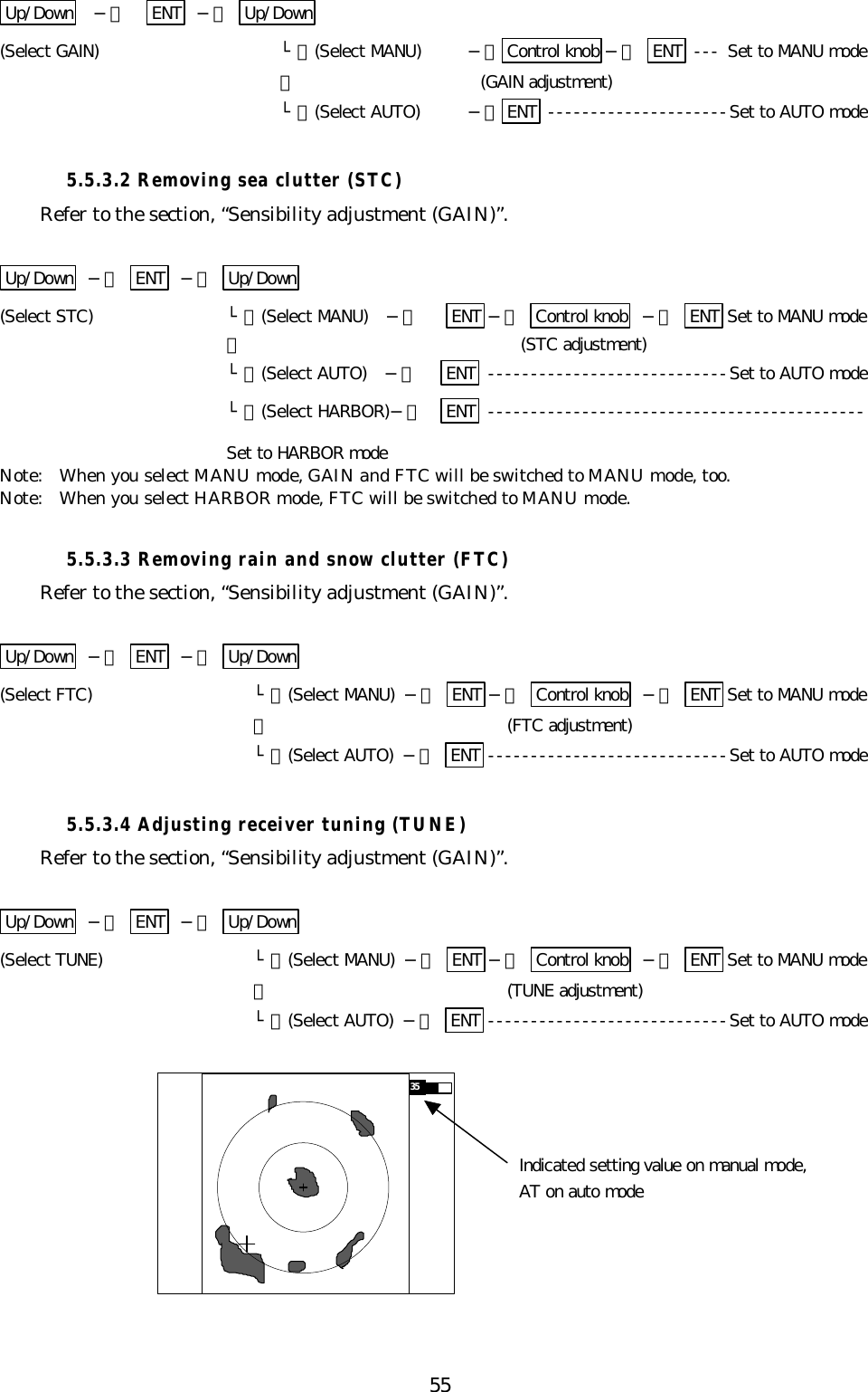
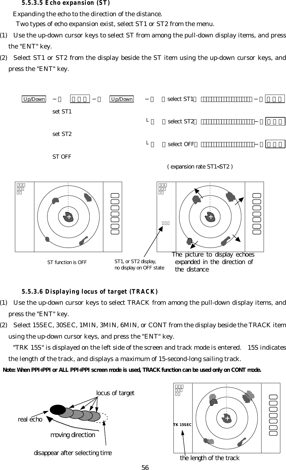
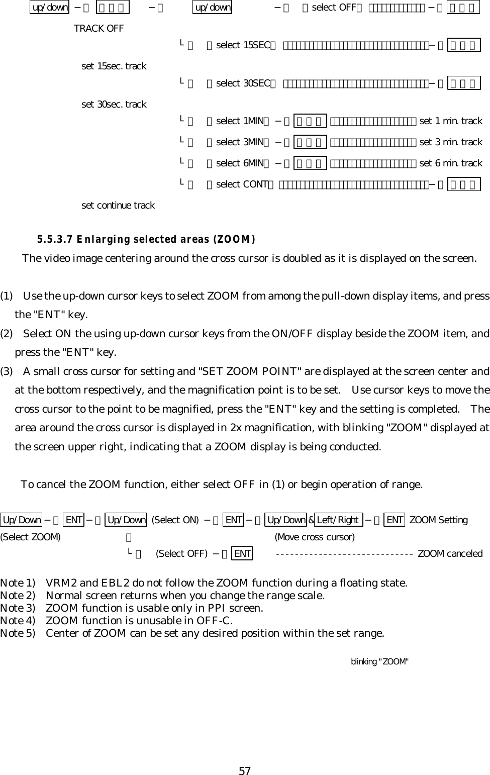
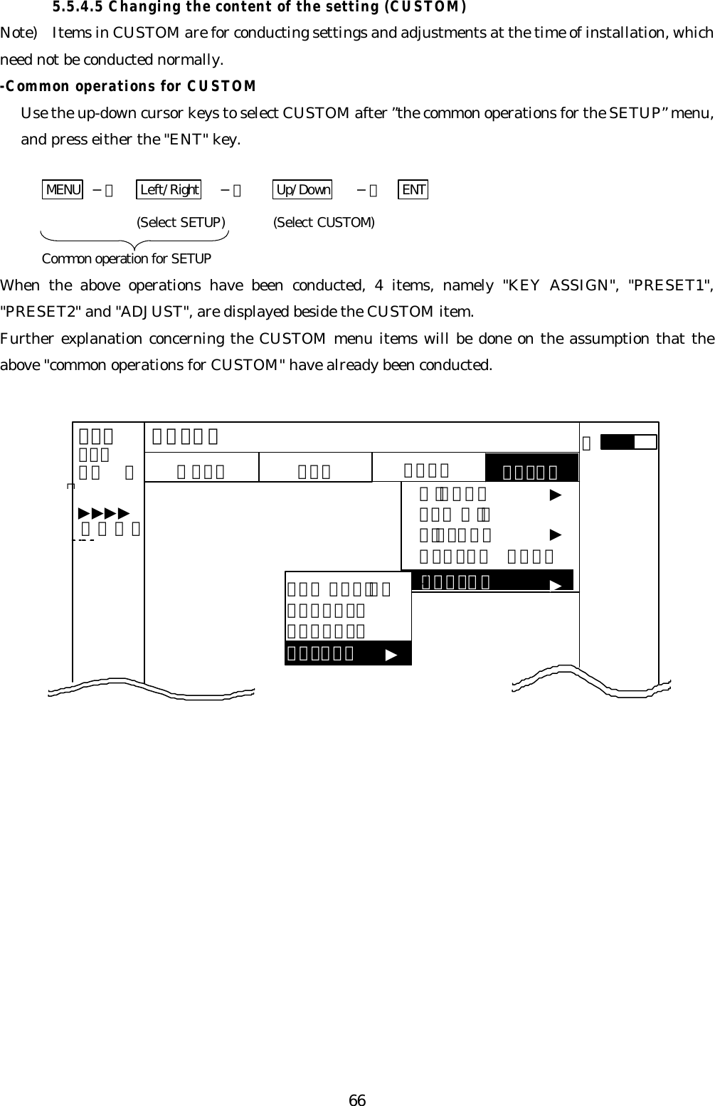
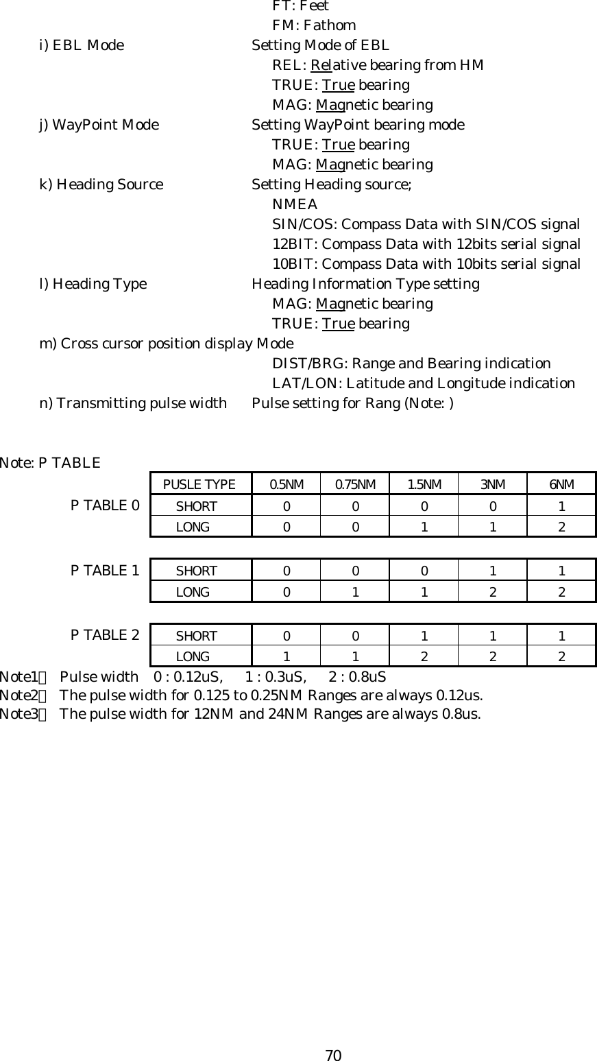
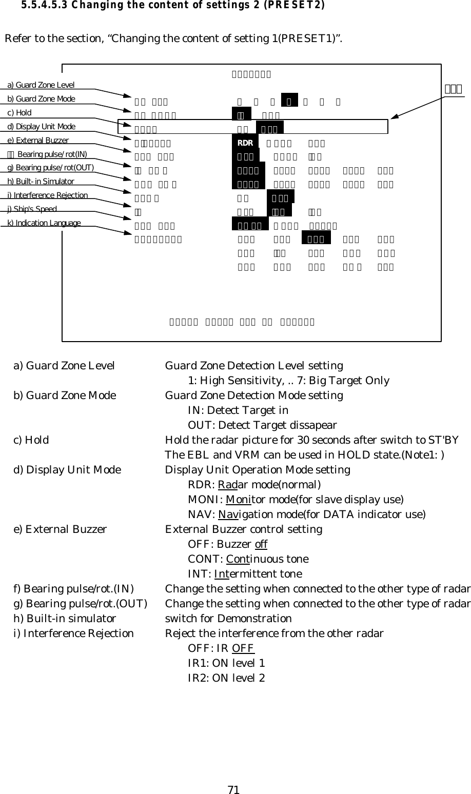
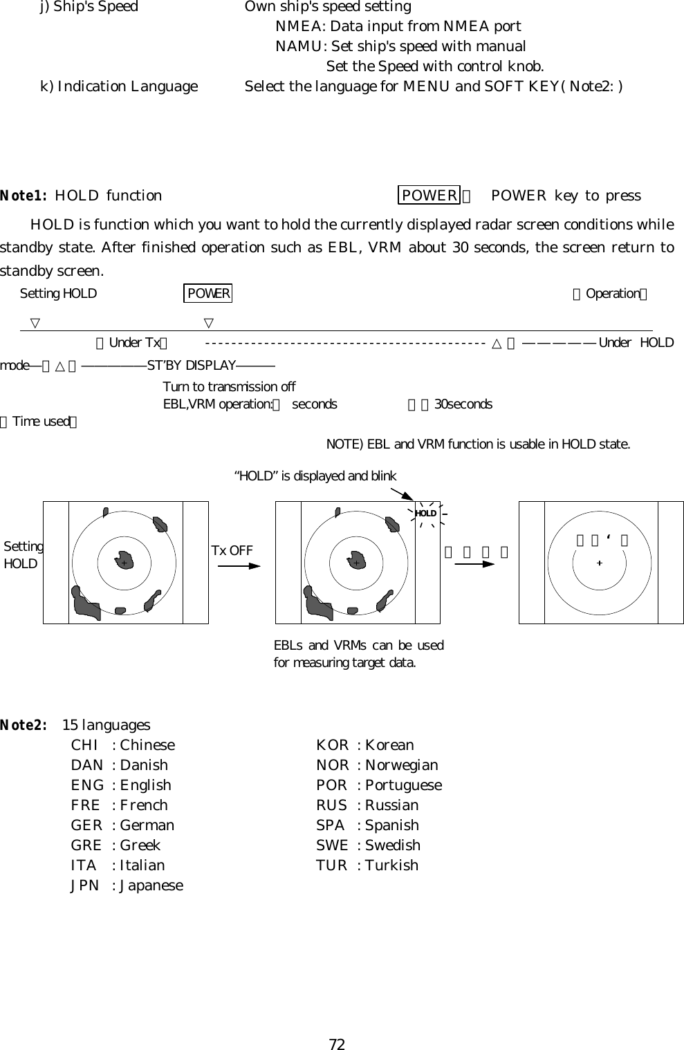
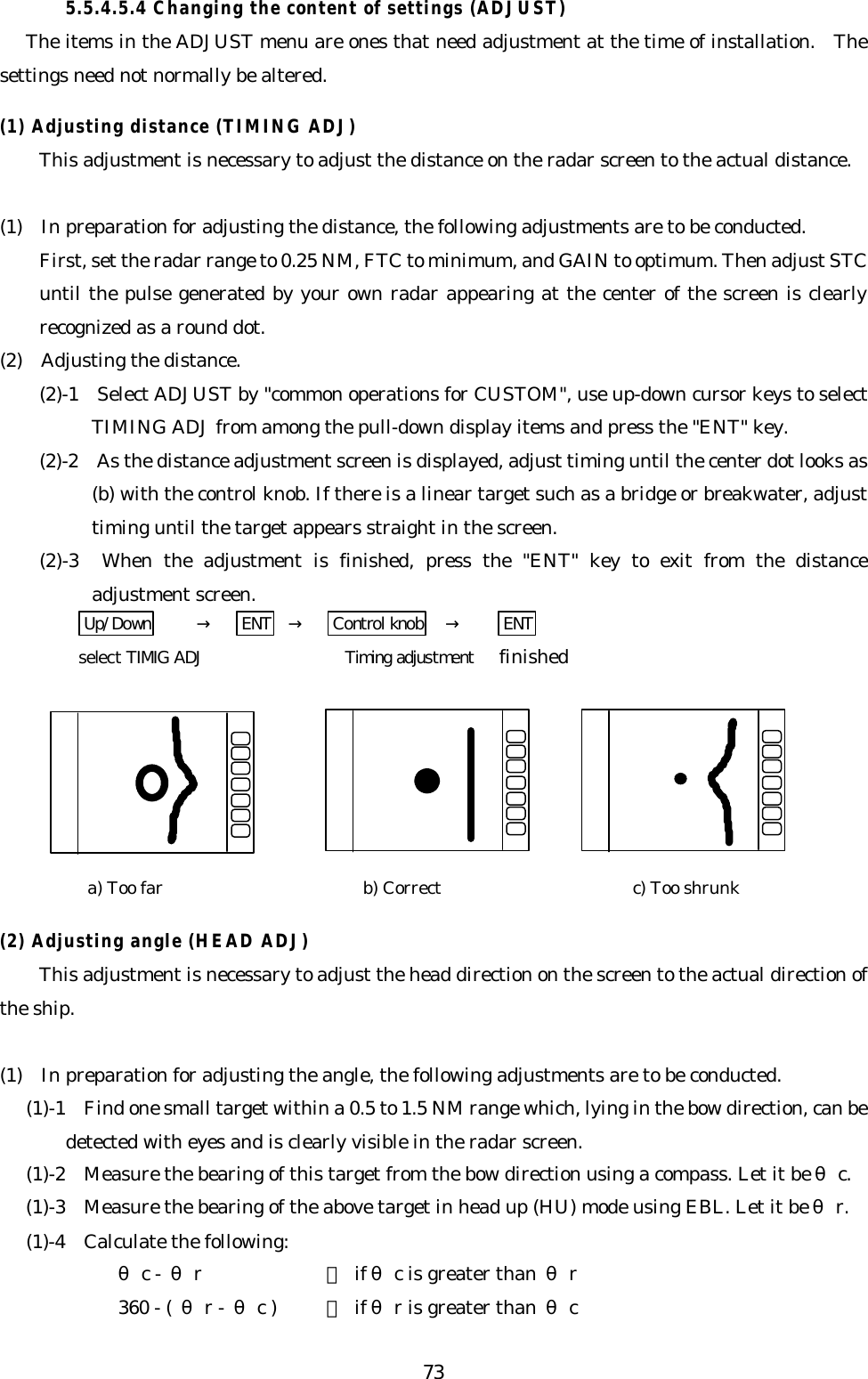
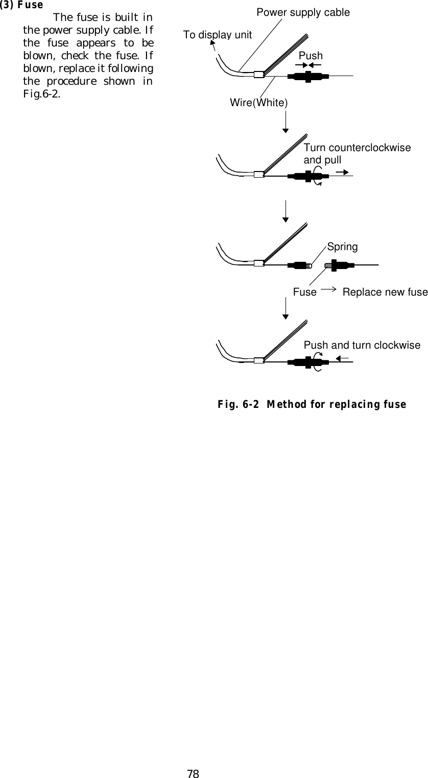
![133.3.3 Shifting away from obstacles• Shifting from keel lineBy shifting the scanner position from the keel line to the starboard side of theship, it is possible to move shadow zones to the port side which makes it possible tokeep clear vision in the bow direction. The distance to be shifted can be obtained bycalculation depending on the distance from the scanner to obstacles using the follow-ing equation:Ls=0.4R+D/2 [m] (when R<15m)Ls=0.025R+D/2 [m] (when R>=15m)where Ls = distance to be shifted from keel lineD = diameter of obstacle on keel lineR = distance from scanner to obstacle‚ Obtaining sufficient dip angleRaise the scanner position so that there is a sufficient dip angle θ available be-tween the line of sight from the scanner to the obstacle and the horizontal line. Byraising the dip angle above 5°, it is possible to prevent mid- and long-distance shadowzones. The radar cannot detect objects below the line of sight.LsRDScanner UnitObstacleKeel lineFig.3-1 Shifting from keel lineHorizontal lineLine of sightθFig.3-2 Obtaining sufficient dip angle](https://usermanual.wiki/Anritsu/6DXRA775UA/User-Guide-80425-Page-22.png)