Anritsu 6DXRA775UA Marine Radar RA775UA User Manual 0 TITLE
Anritsu Corporation Marine Radar RA775UA 0 TITLE
Anritsu >
Users Manual
RA775UA
Marine Radar
Instruction Manual
2nd Edition
Communication Systems Division
Information & Communications Group
ANRITSU CORPORATION
Document : E-A775UA-2-01
• Read this manual before using the equipment.
• Keep this manual.
i
To prevent the risk of personal injury or damage to the equipment, Anritsu Corporation
uses the following safety symbols to indicate safety-related information. Insure that you
clearly understand the meanings of the symbols BEFORE using the equipment.
Symbols Used in Manual
This indicates a very dangerous procedure that could result
in serious injury or death if not performed properly.
This indicates a hazardous procedure that could result in se-
rious injury or death if not performed properly.
This indicates a hazardous procedure or danger that could
result in light-to-severe injury, or that might damage the
equipment, if proper precautions are not taken.
Safety Symbols Used on Equipment
The following safety symbols are used inside or on the equipment near operation loca-
tions to provide information about safety items and operation precautions. Insure that
you clearly understand the meanings of the symbols and take the necessary precau-
tions BEFORE using the equipment.
This indicates high voltages with a risk of serious electric shock if the
part is touched. NEVER touch the part with bare hands, etc.
The symbol prohibits the operation shown inside the symbol. (The
example in the left prohibits disassembly.)
The symbol indicates that the operation inside the symbol is
potentially hazardous. (The example on the left indicates that the plug
should be held when disconnecting it from the AC outlet.)
This indicates the ground (earth) terminal. If the equipment cannot be
grounded via the power cord, connect this terminal to ground. There
is a risk of serious electric shock if the equipment is not grounded.
RA775UA
Marine Radar
Instruction Manual
25th Aug. 1999 (2nd Edition)
14th July. 1999 (1st Edition)
Copyright © 1999, ANRITSU CORPORATION.
All right reserved. No part of this manual may be reproduced without the prior written per-
mission of the publisher. The contents of this manual may be changed without prior notice.
Printed in Japan
Safety Symbols
DANGER
!
WARNING
!
CAUTION
!
ii
・DO NOT OPEN THE COVER EXCEPT SERVICE
PERSONNEL. YOU MAY GET AN ELECTRIC SHOCK.
・SWITCH OFF SHIPS MAIN BEFORE MAINTENANCE.
ROTATING ANTENNA MAY HIT YOU.
・ KEEP OFF DURING TRANSMISSION.
RADIATION LEVEL: 10W/m2 DISTANCE : 1.8m
・ DO NOT DROP COVER.
IT MAY HIT SOMEBODY.
・ サービスマン以外はふたを開けないでください。
感電するおそれがあります。
・作業前に主電源を切って下さい。
回転しているアンテナでけがをするおそれがあります。
・ 送信中に近付かないでください。
放射レベル : 10W/m2 距離 : 1.8m
・ カバーなどを落下させないでください。
下にいる人が危険です。
・DO NOT PAINT THE RADOME.
PERFORMANCE WILL DOWN. ・ レドームにはペンキを塗らないでください。
性能が落ちます。
•There is a risk of receiving electric shock if these parts are touched by
accident. Only qualified personnel should remove covers on these
parts.
‚To avoid accidental antenna rotation, turn off ship’s main and pull off
out the motor fuse during repair inspect, or maintenance.
When repairing or inspecting the scanner unit wear a safety harness
and provide a secure platform so that there is no danger of falling even
when the vessel lists or when there is an unexpected incident such as
an earth quake.
ƒDo not approach the antenna while it is transmitting.
In addition, at inspection never look into the wave guide during trans-
mission.
„When remove the scanner cover etc., do not drop it. It may endanger
people below.
…Do not paint the RADOME. Antenna performance will be down.
For Safety
!
WARNING / 警 告
!
CAUTION / 注 意
③
④
⑤
①
②
iii
・ SEE INSTRUCTION MANUALS BEFORE
CONNECTING POWER.
SAFETY INFORMATION IS WRITTEN IN.
・ EARTH CONNECTION ESSENTIAL
BEFORE CONNECTING POWER.
YOU MAY GET AN ELECTRIC SHOCK.
・ DO NOT OPEN THE COVER EXCEPT
SERVICE PERSONNEL.
HIGH VOLTAGE IS INSIDE.
YOU MAY GET AN ELECTRIC SHOCK.
・ 電源接続する前に、必ず取扱
説明書を読んでください。
安全情報が記載されています。
・ 電源接続する前に、アース接続
を行ってください。
感電のおそれがあります。
・ サービスマン以外は、ふたを
開けないでください。
高圧部分があり、感電のおそれ
があります。
•See instruction manuals before connecting power. Safety information is
written in.
‚Earth connection essential before connecting supply.
There is a risk of serious electric shock if the equipment is not
grounded.
ƒThere is a risk of receiving electric shock if these parts are touched by
accident.
Only qualified personnel should remove covers on these parts.
!
WARNING / 警 告
①
②
③
iv
Installation
Radio laws dictate that this radar may only be installed by properly licensed personnel.
Licensing
You must obtain a license as prescribed by the Radio Law to operate this unit.
Exporting
According to the sales agreement with your distributor, this product is for use only within your
country. When taking it overseas, there may be cases where you must obtain export
permission. Contact Anritsu Corporation or one of our dealers as soon as possible if you are
planning to take the product out of your country.
Equipment Certificate
Anritsu Corporation certifies that this equipment was tested before shipment, to meet recog-
nized standards.
Warranty
Anritsu Corporation warrants this equipment to be manufactured in accordance with pub-
lished specifications and free from defects in materials and/or workmanship.
Anritsu Corporation will repair or exchange any parts except consumable parts proven to be
malfunctioning under normal use for a period of two (2) years. This warranty policy shall not
cover any labor charge.
Limitation of Warranty
Anritsu Corporation’s warranty policy does not apply to product which has been subjected to
accident, abuse, or misuse, shipping damage, alterations, corrosion, incorrect and/or unau-
thorized service or modification, or product which the serial number plate has been altered or
removed.
ANRITSU CORPORATION MAKES NO WARRANTIES, EITHER EXPRESS
OR IMPLIED, EXCEPT AS PROVIDED HEREIN, INCLUDING WITHOUT
LIMITATION PARTICULAR PURPOSE OR USE, OR AGAINST INFRINGE-
MENT OF ANY PATENT. IN NO EVENT SHALL ANRITSU BE LIABLE FOR
ANY DIRECT, INCIDENTAL OR CONSEQUENTIAL DAMAGES OF ANY
NATURE, OR LOSSES OR EXPENSES RESULTING FROM ANY DEFEC-
TIVE PRODUCT OR THE USE OF ANY PRODUCT.
Should you have queries about maintenance, please contact our distributor.
To Customers
* To use this equipment effectively, the operation and maintenance procedure in this manual
must be followed properly. Note that this equipment is only a navigational instrument having
no warrant for navigation safety. Non-execution of fundamental navigation requirements
such as the ship location check or lookout is not allowed.
* If some abnormality occurs in this equipment, immediately turn off the equipment POWER
switch and the radar main switch in the power distribution board and notify our maintenance
section or dealer.
* This instrument uses oscillator and LCD backlight. They are easy to be broken. Do not sub-
ject the instrument to excessive force or drop it.
* The mercury (Hg) is used in LCD backlight. When you discard your radar, it is due to laws or
regulations of your nations.
v
Contents
For safety
CHAPTER 1 OVERVIEW.................................................................................1
1.1 Introduction.......................................................................................................1
1.2 Organization of This Manual............................................................................1
CHAPTER 2 USING RADAR FOR THE FIRST TIME...................................2
2.1 What is a radar ?...............................................................................................2
2.2 Characteristics of Radar Wave..........................................................................3
2.3 Terms Specific to Radars...................................................................................6
CHAPTER 3 INSTALLATION.........................................................................10
3.1 Checking Contents of Your Package.................................................................10
3.2 Checking Power Supply Voltage.......................................................................11
3.2.1 Power Supply Requirement .........................................................................11
3.2.2 Fuse Replacement ........................................................................................11
3.3 Determining Place of Installation.....................................................................12
3.3.1 Scanner unit.................................................................................................12
3.3.2 Display unit..................................................................................................12
3.3.3 Shifting away from obstacles .......................................................................13
3.4 Installing Scanner Unit ....................................................................................14
3.5 Installing Display Unit .....................................................................................15
3.6 Connecting Cables.............................................................................................17
3.6.1 Interconnecting cable...................................................................................17
3.6.2 Grounding wire ............................................................................................19
3.6.3 Power supply cable.......................................................................................20
3.7 Adjustment........................................................................................................21
3.8 Connecting External Equipment to Display Unit ............................................21
3.9 Countermeasure for Electromagnetic Interference..........................................22
3.10 When Discarding Your Radar.........................................................................23
CHAPTER 4 FUNCTIONS AND NAMES....................................................... 24
4.1 Key layout .........................................................................................................24
4.2 Rear panel .........................................................................................................25
4.3 Radar screen (Single screen).............................................................................25
4.4 Radar screen (Dual screen)...............................................................................26
4.5 Radar screen (All PPI screen)...........................................................................26
4.6 Radar screen (All PPI/PPI screen)....................................................................27
4.7 Navigation screen..............................................................................................27
CHAPTER 5 OPERATION...............................................................................28
Basic operation of Radar.........................................................................................28
5.1 Powering On and Off.........................................................................................28
5.2 Adjusting contrast and brilliance of the screen, and key-backlight.................28
5.3 Basic Operations ...............................................................................................29
5.3.1 Powering On and Off....................................................................................29
5.3.2 Transmitting ................................................................................................29
5.3.3 Adjusting contrast and brilliance of the screen, and key-backlight............30
vi
5.3.4 Changing Distance Range (RANGE UP, RANGE DOWN)......................... 30
5.3.5 Automatic adjustment (AUTO).................................................................... 30
5.3.6 Sensitivity adjustment (GAIN).....................................................................31
5.3.7 Removing sea clutter (STC)..........................................................................31
5.3.8 Removing rain and snow clutter (FTC)........................................................32
5.3.9 Man Over Board (MOB)............................................................................... 32
5.4 Functions of Soft Keys...................................................................................... 33
5.4.1 Bearing measurement (EBL1)..................................................................... 33
5.4.2 Bearing measurement (EBL2)..................................................................... 33
5.4.3 Distance measurement (VRM1)................................................................... 33
5.4.4 Distance measurement (VRM2)................................................................... 34
5.4.5 Measuring the angle between two points (FL EBL2).................................. 34
5.4.6 Measuring the distance between two points (FL VRM2)............................ 34
5.4.7 Changing the group of Soft Keys(NEXT) .................................................... 35
5.4.8 Erasing heading maker temporarily (HDG OFF) ....................................... 36
5.4.9 Using parallel cursors (///CSR) .................................................................... 36
5.4.10 Establishment of the indication of the RANGE RINGS (RINGS)............. 36
5.4.11 ON/OFF of variable range function (VAR RNG)....................................... 36
5.4.12 Changing display modes (MODE).............................................................. 36
5.4.13 Guard Zone (GZ) ........................................................................................ 36
5.4.14 Off Center (OFF-C) .................................................................................... 37
5.4.15 Setting of the SLEEP function(SLEEP)..................................................... 38
5.4.16 Tuning adjustment (TUNE)....................................................................... 38
5.4.17 Echo expansion (ST)................................................................................... 39
5.4.18 Displaying locus of target (TRACK)........................................................... 39
5.4.19 Enlarging selected areas (ZOOM).............................................................. 39
5.4.20 Increasing sensitivity (S/L)........................................................................ 40
5.4.21 Switching the screen (SEL WIN)............................................................... 40
5.4.22 Reversing the screen (PICTURE).............................................................. 40
5.4.23 Change to PPI screen (PPI) ....................................................................... 41
5.4.24 Change to SEMI3D/PPI screen (SEMI3D) ................................................ 41
5.4.25 Change to PPI/PPI screen (PPI/PPI) ......................................................... 41
5.4.26 Change to PPI/NAV screen (PPI/NAV)...................................................... 42
5.4.27 Change to ALL PPI screen (ALL PPI)....................................................... 42
5.4.28 Change to ALL PPI/PPI screen (ALL PPI2).............................................. 42
5.5 MENU Operation.............................................................................................. 43
-
List of MENU.................................................................................................... 43
5.5.1 Mark Menu .................................................................................................. 44
5.5.1.1 Bearing measurement (EBL1)................................................................. 44
5.5.1.2 Determining the distance (VRM1)........................................................... 45
5.5.1.3 Bearing measurement (EBL2)................................................................. 45
5.5.1.4 Determining the distance (VRM2)........................................................... 45
5.5.1.5 Measuring the distance or angle between two points ( FL EBL2, FL VRM2 )
......................................45
5.5.1.6 Measuring the angle between two points (FL EBL2).............................. 46
5.5.1.7 Erasing heading maker temporarily (HDG OFF) ................................... 47
5.5.1.8 Using parallel cursors (///CSR) ................................................................ 47
5.5.1.9 Establishment of the indication of the RANGE RINGS (RINGS)........... 48
5.5.1.10 Variable range function ( VAR RNG ) ................................................... 48
5.5.1.11 Output the position data of Cursor (TARGET)...................................... 49
5.5.1.12 Follow the Distance and Bearing marker on the cursor (+MK LINE).. 49
5.5.2 Nav (Navigation) Menu ................................................................................ 50
vii
5.5.2.1 Changing display mode (MODE)............................................................50
5.5.2.2 Guard Zone (GZ)......................................................................................51
5.5.2.3 Shifting display in specific direction (OFF-C)..........................................52
5.5.2.4 Setting of the SLEEP function(SLEEP)...................................................52
5.5.3 Echo Menu......................................................................................................54
5.5.3.1 Sensibility adjustment (GAIN).................................................................54
5.5.3.2 Removing sea clutter (STC)......................................................................55
5.5.3.3 Removing rain and snow clutter (FTC)....................................................55
5.5.3.4 Adjusting receiver tuning (TUNE)...........................................................55
5.5.3.5 Echo expansion (ST).................................................................................55
5.5.3.6 Displaying locus of target (TRACK) ........................................................56
5.5.3.7 Enlarging selected areas (ZOOM) ...........................................................57
5.5.3.8 Increasing sensitivity (S/L) ......................................................................57
5.5.4 SETUP Menu...............................................................................................59
5.5.4.1 Initiating the screen display (WINDOW) ................................................59
- The limitation of the screen operation..............................................................60
- Screen modes and Operations ...........................................................................60
(a) PPI Screen .............................................................................................60
(b) PPI/SEMI3D Screen ..............................................................................61
(c) PPI/PPI Screen.......................................................................................61
(d) PPI/NAV Screen ....................................................................................62
(e) ALL PPI Screen .....................................................................................62
(f) ALL PPI/PPI Screen...............................................................................62
(g) MOB Screen...........................................................................................63
5.5.4.2 Switching screens on PPI/PPI screen (SEL WIN) ...................................63
5.5.4.3 Reversing the screen (PICTURE) ............................................................63
5.5.4.4 Fault Diagnosis by Self Check (SYSTEM CHECK).................................64
5.5.4.5 Changing the content of the setting (CUSTOM) .....................................66
5.5.4.5.1 Changing the settings of soft keys (KEY ASSIGN) .............................67
5.5.4.5.2 Changing the content of settings 1(PRESET1)....................................69
5.5.4.5.3 Changing the content of settings 2 (PRESET2)...................................71
5.5.4.5.4 Changing the content of settings (ADJUSTMENT)..............................73
(1) Adjusting distance (TIMING ADJ)......................................................73
(2) Adjusting angle (HEAD ADJ)..............................................................73
(3) Adjusting tuning circuit (TUNING CAL) ............................................74
(4) Adjusting antenna height (ANTENNA)...............................................75
(5) Setting automatic gain circuit (AUTO GAIN) .....................................76
(6) Setting automatic STC circuit (AUTO STC)........................................76
(7) Setting HARBOR STC circuit (HARBOR)...........................................76
CHAPTER 6 MAINTENANCE AND INSPECTION.......................................77
CHAPTER 7 TROUBLESHOOTING............................................................... 79
7.1 Fault Diagnosis by Self-check...........................................................................79
7.2 Inspecting Each Part.........................................................................................80
CHAPTER 8 PRODUCT SPECIFICATIONS ..................................................81
8.1 General...............................................................................................................81
8.2 Scanner Unit ......................................................................................................82
8.3 Display Unit .......................................................................................................82
viii
8.4 External Interface..............................................................................................83
8.5 Standard set.......................................................................................................83
8.6 Options...............................................................................................................84
8.7 External dimensions and weight.......................................................................84
8.8 External Interface..............................................................................................84
APPENDIX
1. GENERAL SYSTEM DIAGRAM 24W160941
2. INTERCONNECTION DIAGRAM 24W160939
3. OUTLINE DRAWING DISPLAY UNIT 23W72646
4. OUTLINE DRAWING SCANNER UNIT 23W68739
5. FLUSH MOUNT PROCEDURE
6. TEMPLATE OF SCANNER MOUNTING HOLES (ACTUAL SIZE)
7. INDEX

1
CHAPTER 1 OVERVIEW
●1.1 Introduction
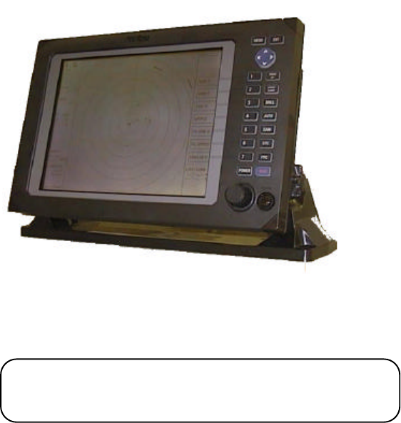
The RA775UA represents a compact, high-performance marine radar that delivers a peak
power output of 2 kW from the antenna and uses an 10-inch monochrome liquid crystal display.
In addition to a microcomputer, it incorporates a video signal processing LSI and a newly
developed LSI chip exclusively designed for radars, thus providing versatile functionality and
high performance.
Features
1. A thin display unit incorporating a liquid crystal display.
2. Easy operation using only a few keys and menu screens.
3. A position of key and its function can be set in position ( Selectable soft function key).
4. Easy operation by the rotary knob.
Gain, STC, FTC, EBLs, VRMs etc. can be controlled by the rotary knob.
4. A short and a long range echo can be seen at a time ( Dual range radar).
5. Semi-3D screen display for easy identification of targets in noise.
6. Capable of continuous distance range changes (Continual variable range).
7. Waterproof construction of display allows installation at any desired location.
●1.2 Organization of This Manual
This manual provides a wide range of information necessary to operate the RA775UA ra-
dar ranging from the basic knowledge on radars to the methods of operating, installing, and
maintaining the RA775UA radar. The manual also provides rather detailed technical informa-
tion on how to adjust video display to obtain clear images. Anritsu recommends you to read
this manual thoroughly from beginning to end in order to understand the various functions of
the RA775UA radar so you can take full advantage of its advanced functions. If you are using a
radar for the first time, refer to the basic data on radars in CHAPTER 2.
This manual consists of the following chapters:
USING RADAR FOR THE FIRST TIME ...................... CHAPTER 2
INSTALLATION ...................... CHAPTER 3
FUNCTIONS AND NAMES ...................... CHAPTER 4
OPERATION ...................... CHAPTER 5
INSPECTION AND MAINTENANCE ...................... CHAPTER 6
TROUBLESHOOTING ...................... CHAPTER 7
PRODUCT SPECIFICATIONS ...................... CHAPTER 8
If you are an experienced user of radars, skip CHAPTER 2 and begin from CHAPTER 3.
2
CHAPTER 2. USING RADAR FOR
THE FIRST TIME
This chapter describes basic information on radars and explains technical terms used in ra-
dar operation for those who is using a radar for the first time.
●2.1 What is a radar ?
A marine radar is one of the navigation equipment installed on a ship. It emits a radio wave
in very high frequency called a microwave from its antenna and receives the reflected radio wave
from objects on the sea (e.g., other ships, buoys, and lands). The received radio wave is converted
into an electric signal which is displayed on a display screen to indicate the presence of such ob-
jects. Although it is very difficult to find other ships or the destination coast with human eyes at
night or in thick fog, a radar helps you detect objects on the sea helping you avoid danger when
sailing. The antenna turns 360 degrees as it radiates waves, allowing you to grasp ambient
conditions around your ship at a glance.
The radio wave radiated from the antenna is called a pulse wave and the radar performs
transmission and reception alternately. Several hundred to several thousand pulse waves gener-
ally are transmitted while the antenna rotates one turn.
Antenna
There are many types of antennas generally used for a
radar. For example, these include a parabolic antenna and a
slotted-array antenna. The performance of the antenna
determines that of the radar. The dominant factors are the
antenna's beam width and side lobe level. The narrower the
beam width, the higher the resolution of the angle direction.
The lower the side lobe level, the fewer the effect of a false echo.
Side lobe
A beam in one direction in which the strongest radio
wave is radiated from the antenna is called the main lobe
and beams in other directions are called "side lobes". The
side lobe level refers to the difference in level between
the largest side lobe and the main lobe.
Buoy
Other ship Radar wave
Your ship Antenna (Rotating)
Radar display
Fig.2-1 What is a radar?
Beam width
Side lobe
level
Main beam
Side lobe
Antenna
Fig.2-2 Antenna pattern
3
Beam width
A beam width is defined as the width of the main lobe at an angle where the radiated
power is halved as measured from the position from which the strongest radio wave is radi-
ated.
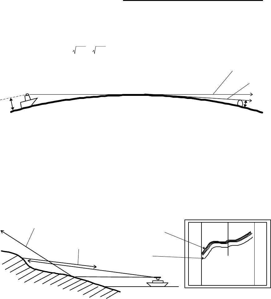
●2.2 Characteristics of Radar Wave
Radio waves from the radar propagate while bending slightly along the terrestrial surface.
This characteristic varies dependent on the density of the atmospheric air. The sight distance D of
a radar generally is said to be approximately 6% longer than the optical sight distance and is
calculated using the equation below :
D (NM) = 2.22 ( h1 + h2 ) where, h1= antenna height in meters
h2= target height in meters
Fig.2-3 Radar wave
Targets difficult to display on screen
The intensity of the reflected wave from a target depends on the distance, height, and
size of the target, as well as its material and shape. Targets constructed with FRP, wood, or
other low-reflectance materials or those that have a small incident angle are difficult to dis-
play on a screen. Therefore, FRP and wooden ships, sandy beaches, and sandy or muddy
shallows all are difficult to catch and require attention when monitoring on the screen. Es-
pecially, coast lines on the radar image appear to be present more apart from the ship than
they are actually located. Therefore, it is important not to misinterpret the available data.
Shadow zones of radar
Radar waves are characteristic in that they propagate straight ahead. Therefore, if the
ship's smokestack or mast is located near the antenna or there is a tall ship or mountain at
the side of the ship, such an object generates a shadow behind it. In this case, some objects
produce a complete shadow and some produce a partial shadow. In an extreme case, the
Apparent coastline
Actual(invisible)
coastline
Invisible
Visible
3
1
HU
Fig.2-4 Targets difficult to display on screen
h1 h2
Line of sight
Radar Radio
Wave
Earth
4
shadow of an object may extend to a position far away and cannot be displayed on the screen
at all. Since these shadows can be discovered when installing an antenna, the problem can
be avoided by changing the place of antenna installation to minimize the shadow. Targets in
shadow zones are difficult to display on the screen.
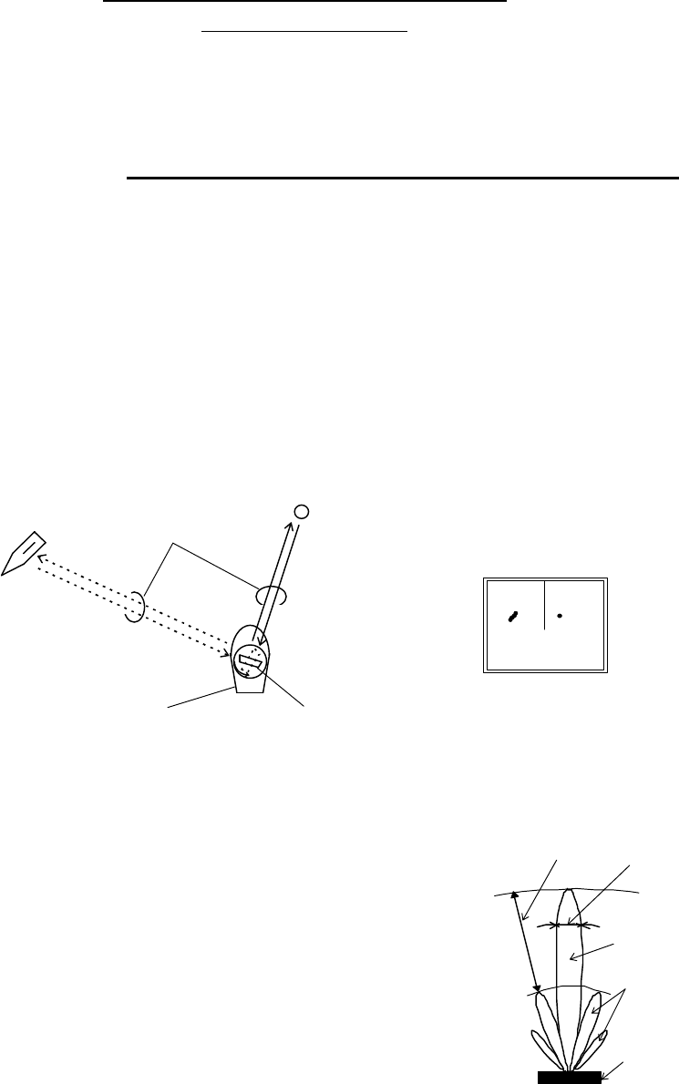
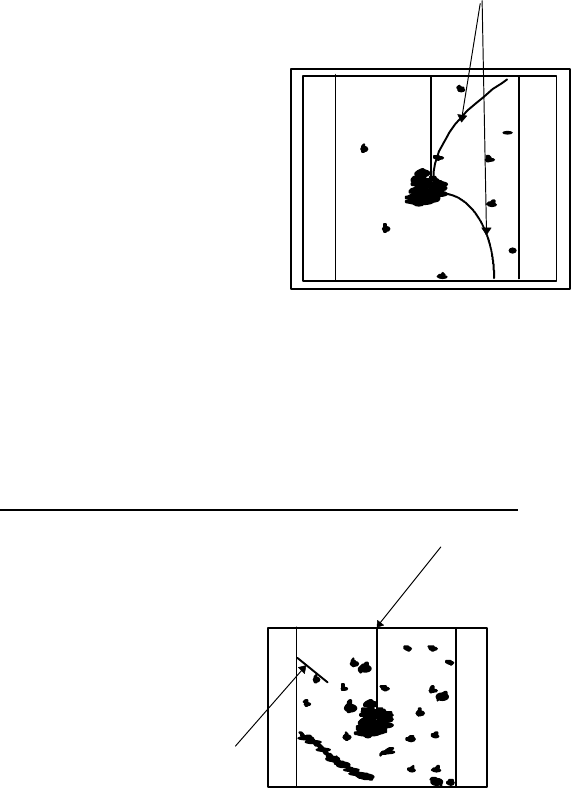
False echoes
A false echo of an actually nonexistent object may sometimes appear on the screen
when sailing. The following explains the cause of each of such phenomena.
A. Ghost echoes
It sometimes happens that one large object near the ship appears at two different bear-
ings. One is the actual echo and other is a ghost echo generated as the wave is re-reflected
from the ship's own smokestack or mast. The former appears at the correct distance and
bearing on the screen and the latter appears behind the smokestack or mast. This type of
false echo is also generated by re-reflection of waves from bridges and quay walls other than
the ship itself.
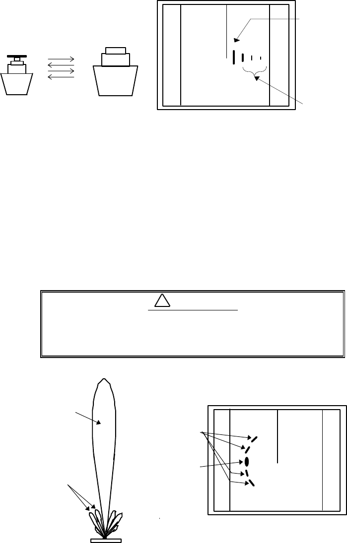
B. Multiple echoes
If there is a large vertical reflecting plane near the ship as in the case when your ship
passes alongside a large ship, the wave is repeatedly reflected back and forth between your
ship and the other object. For this reason, two to four images appear on the screen at equal
intervals in the same bearing. A false echo that is generated by such multiple reflections is
called multiple echoes. In this case, an image appearing at the nearest position is the real
echo. Multiple echoes disappear as the ship moves away from the reflecting object or its
bearing changes. Therefore, it is not difficult to determine the correct image.
Target
Direct reflection
path
Secondary
reflection path
Mast etc.
Real echo
Ghost echo
Direction of ghost echo
3
1
HU
Fig.2-5 False echoes of radar (Ghost echoes)
5
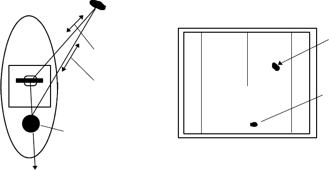
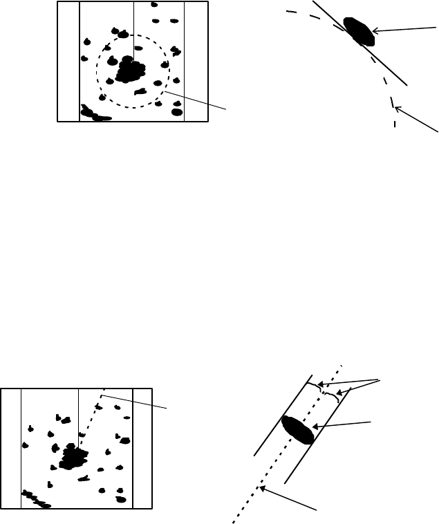
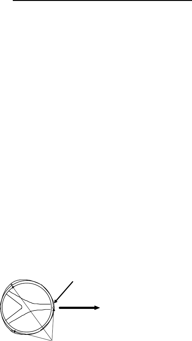
C. False echoes caused by side lobe
The radiant beam emitted from an antenna contains side lobes in directions other than
that of the main beam. Since the side lobe level is low, it in no way affects distant targets.
However, if there is a strong reflecting target near the ship, it sometimes appear as a circu-
lar-arc false echo on the screen.
When located near large targets such as land, the
ship's mast, etc. sometimes appears as a false echo
of circular-arc shape.
3
1
HU Real echo
Multiple
echoes
Fig.2-6 False echoes of radar (Multiple echoes)
3
1
HU
Antenna
Main beam
Side lobes
Real echo
False sidelobe
echoes
Fig.2-7 False echoes of radar (Caused by side lobe)
CAUTION
!
6
D. Distant false echoes caused by duct phenomenon
Depending on meteorological conditions, duct phenomenon sometimes occurs in tem-
perature inverting layers of air. In such a case, the wave propagates erratically reaching a
location surprisingly far away from the ship. In this case, a target present at a distant loca-
tion more than the radar's maximum distance range appears on the screen presenting a
false echo that can be misunderstood to be present nearer than the actual position. This
phenomenon is attributed to the fact that since echo from the distant target arrives late, it
gets out of the pulse repetition frequency and is displayed on the screen as an echo in the
next frequency. If the target distance changes as you switch over the distance range, you
can determine that it is a false echo.
Radar interference
If a radar operating in the same frequency exists near
your ship, interference noise may appear on the screen that is
caused by transmitted waves from that radar. This interfer-
ence appears in various ways. In most cases, however, it ap-
pears as spiral or radial patterns.
The RA775UA radar has a function to eliminate interfer-
ence. Use of this function helps you minimize interference.
●
2.3 Terms Specific to Radar
HM (Heading Marker)
This is a line-shaped marker used to indicate
the advancing direction of your ship.
North Mark
This marker indicates the north direction. It
is a short line approximately 1/6 of the screen
size.
3
1
HU
Radar inrterference
Fig.2-8 Radar interference
0.75
0.25
HU
HM(Heading Marker)
North Mark
Fig.2-9 Heading Marker and
North Mark
7
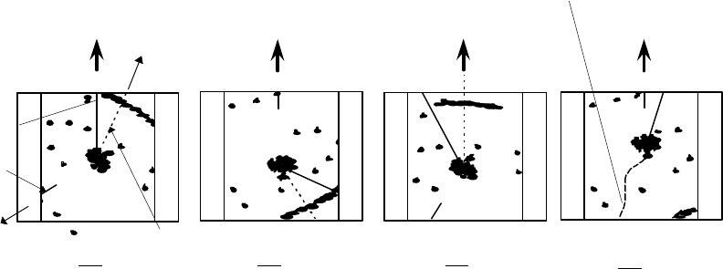
Display modes
This refers to a radar's display modes. There are four display modes depending on the direc-
tion in which the top of the screen faces with respect to the ship.
Head Up (HU)
In this mode, the ship's heading always indicates the upward direction of the screen.
This mode lets you know the relative positions of your ship and other ships or land.
North Up (NU)
In this mode, the north direction always indicates the upward direction of the screen,
allowing you to compare your ship position with a marine chart as you navigate.
Course Up (CU)
The ship's heading in a course-up mode always indicates the upward direction of the
screen as the bearing toward the destination. In this mode, the ship can be maneuvered to
sail the shortest distance to the destination by steering it in such a way that its heading
marker always directs to the upward direction of the screen. If the ship drifts due to tidal
current, care must be taken because the fixed targets move to other positions.
True Motion (TM)
In this mode, the ship is displayed as if it is moving on a marine chart while the fixed
targets such as islands and seashores are fixed in position. When the ship reaches a certain
position on the screen (approx. 2/3 of screen size), the ship is placed back to the opposite side
on the screen. (The top of the screen faces north.)
Note: Navigation equipment such as a gyrocompass or magnet compass must be connected
to your radar system before it can be operated in NU, CU, and TM modes. (Refer to Section
3.9 for details on how to connect your radar to navigation equipment.)
Ship's
Heading
North
Scheduled
course
HM
EBL
North
mark
HU NU CU TM
Ship's locus
(not displayed on screen)
NorthNorth Scheduled
course
0.75 0.75 0.75 0.25
TM
0.25
CU
0.25
NU
0.25
HU
0.75
Fig.2-10 Display modes
8
VRM (Variable Range Marker)
This is a circular-shaped marker whose size can be changed as desired. You can use this
marker when you want to examine the distance of an echo from your ship.
When measuring the distance of an echo from your ship, be sure to measure at a point close
to the center of the echo image on the screen.
EBL (Electronic Bearing Line)
This is a marker shaped like a straight line segment that can be changed to any direction
centering around the ship position. Use this marker to examine the advancing direction of your
ship and its relative angle with an echo. When measuring the angle of an echo, position the
marker at the center of the echo.
VRM
Echo
0.75
0.25
HU
VRM
Fig.2-11 VRM
0.75
0.25
HU EBL Echo
EBL
Equal intervals
Fig.2-12 EBL
9
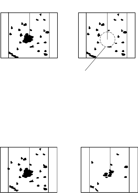
STC (Sensitivity Time Control)
Since echo signals received by the radar are strong when they are coming from a short dis-
tance, it is difficult to compare signal strength between each reflected signal. To overcome this
difficulty, signal strength is adjusted in such a way that the received signal levels coming from a
short distance are lowered and those from a long distance are raised. This function should prove
useful when there are large reflected waves from sea surfaces during rough weather.
FTC (Fast Time Constant)
When it rains or snows, fine noise may appear over the entire screen, making it difficult to
identify echoes. In such a case, echo images on the screen can be made easily distinguishable by
adjusting FTC.
0.75
0.25
HU
STC OFF STC ON
0.75
0.25
HU
Echo is suppressed
around center
Fig.2-13 STC
0.75
0.25
HU
FTC OFF FTC ON
0.75
0.25
HU
Small noises
are reduced.
Fig.2-14 FTC
10
CHAPTER 3. INSTALLATION
This chapter describes procedures for installing the RA775UA radar in your ship and precau-
tions to be observed during installation. Follow the procedure below to install the radar.
●3.1 Checking Contents of Your Package
First, unpack your package and see if all of the following items are included.
Item QTY
Display unit 1 (RF718A)
Scanner unit 1 (RB714A)
Display cover 1
Fuse 2
Interconnecting cable 1 (10 m)
Power supply cable 1 (2 m)
M10 hexagonal bolt 4 sets
The package contains a 10m interconnecting cable as an accessory. Longer cable is also
available as an option as listed in Tab.3-1.
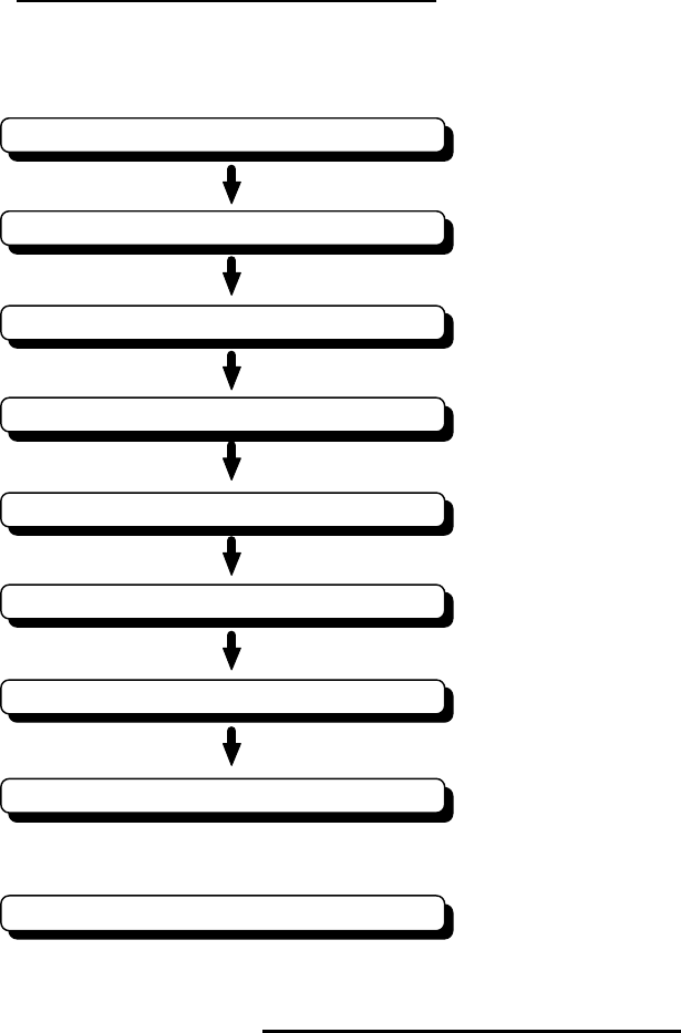
Checking contents of your package
Checking power supply voltage
Determining place of installation
Installing scanner unit
Installing display unit
Connecting cables
Adjustment
Connecting external equipment
When discarding Your radar
11
Tab.3-1 Optional Interconnecting Cable
In addition to the above components included with your package, the following items are also
required. Please prepare them separately.
Item QTY Remarks
Tapping screw or M5 bolt and nut 6 sets To install display unit
Grounding wire 1Earth line for display unit
Grounding wire and crimp terminal 1 set Earth line for scanner unit
●3.2 Checking Power Supply Voltage
3.2.1 Power Supply Requirements
For the RA775UA radar to be operated normally, the power supply (battery) detailed in
Tab.3-2 is required. Note also that if the battery is discharged, its voltage may fluctuate greatly,
causing the radar to malfunction. When start up the radar system or start transmitting, an addi-
tional rush current is required on the power line. Carefully check the power supply system includ-
ing wiring by using a circuit tester.
Tab.3-2 Power Supply Requirements
*A.C. power cannot be used
3.2.2 Fuse Replacement
For the RA775UA radar to be operated safely, proper rating fuses must be used. Tab.3.3 is
the fuse rating table. Please check them and replace to the fuse in the package.
Tab.3-3 Supply Voltage to Fuse Table
Note: Marked * fuses are in the set as standard.
Cable length Ordering Product No.
15m 242J160680B
20m 242J160680C
30m 242J160680D
Supply voltage used Maximum current Allowable range of voltage
DC12V 5A 10.2-41.6V
DC24V 2.5A 10.2-41.6V
Supply voltage used Main Fuse Motor Fuse
DC12V 8A/250V or 125V *
(6.3Φ x 32mm) T3.15A/250V or 125V *
(5Φ x 20mm)
DC24V 8A/250V or 125V
(6.3Φ x 32mm) T3.15A/250V or 125V
(5Φ x 20mm)
12
●3.3 Determining Place of Installation
3.3.1 Scanner unit
A radar's target detection capacity varies greatly depending on the fitted position of the scan-
ner. An ideal fitting position is a location high above the ship's keel line where there is no obstacle
all around the scanner. In an actual ship, such an ideal location is limited by various factors.
Therefore, consider the following suggestions when you determine the place to install the scanner:
(a) Install scanner at a position as high as possible.
The higher the installation position, the longer the radio ranging distance. In-
stall the scanner at a position as high as possible after considering the ship's hull
structure and radar maintainability.
(b) Install scanner away from smoke-stack and mast
If the scanner is installed at the same height as the smoke-stack or mast, radar
waves may be blocked, creating shadow zones or generating false echoes. Therefore,
do not install the scanner at such a position.
(c) Install scanner forward away from obstacle.
To avoid creating shadow zones or generating false echoes, install the scanner at
a position nearer to the ship's bow away from obstacles. When installing the scanner
on a mast, position it in front of the mast. (If obstacles cannot be avoided for the ship's
structural reasons, refer to "Shifting away from obstacles" described Page 13.)
(d) Do not install the scanner near hot or heat-generating items.
Do not install the scanner at a position where it may be subjected to smoke or hot
air from smokestacks or heat from lamps.
(e) Install the scanner away from antennas of other equipment.
Install the scanner as much away from the antennas of a direction finder, radio
transceiver, etc. as possible.
To eliminate the interference, install the scanner
away from the antenna of radio transceivers.
(f) Make the cable length as short as possible.
Keep the distance from the scanner to the display unit within the standard cable
length of 10 m. If you use longer cable for unavoidable reasons, limit the cable length
to a maximum of 30 m.
3.3.2 Display unit
The display unit can be installed on desktop, wall surface, or ceiling. Determine the place to
install the display unit that is convenient for navigation and radar operation after considering the
following suggestions:
(a) A place where you can see the ship's bow when you raise your face from the
radar screen.
(b) A place where there is no direct sun-light to avoid display temperature up.
(c) A place where there is good ventilation and minimum vibration.
(d) A place where the display unit is apart more than the minimum safe distance
from a magnet compass as listed in Tab.3-3 below.
Tab.3-5 Minimum Safe Distance from Magnetic Compass
Master compass Steering compass
Scanner unit
2.0m 1.4m
Display unit
2.0m 1.4m
!CAUTION
13
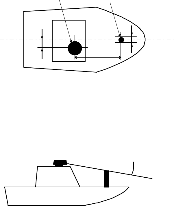
3.3.3 Shifting away from obstacles
•
Shifting from keel line
By shifting the scanner position from the keel line to the starboard side of the
ship, it is possible to move shadow zones to the port side which makes it possible to
keep clear vision in the bow direction. The distance to be shifted can be obtained by
calculation depending on the distance from the scanner to obstacles using the follow-
ing equation:
Ls=0.4R+D/2 [m] (when R<15m)
Ls=0.025R+D/2 [m] (when R>=15m)
where Ls = distance to be shifted from keel line
D = diameter of obstacle on keel line
R = distance from scanner to obstacle
‚
Obtaining sufficient dip angle
Raise the scanner position so that there is a sufficient dip angle θ available be-
tween the line of sight from the scanner to the obstacle and the horizontal line. By
raising the dip angle above 5°, it is possible to prevent mid- and long-distance shadow
zones. The radar cannot detect objects below the line of sight.
Ls
R
D
Scanner Unit
Obstacle
Keel line
Fig.3-1 Shifting from keel line
Horizontal line
Line of sight
θ
Fig.3-2 Obtaining sufficient dip angle
14
●3.4 Installing Scanner Unit
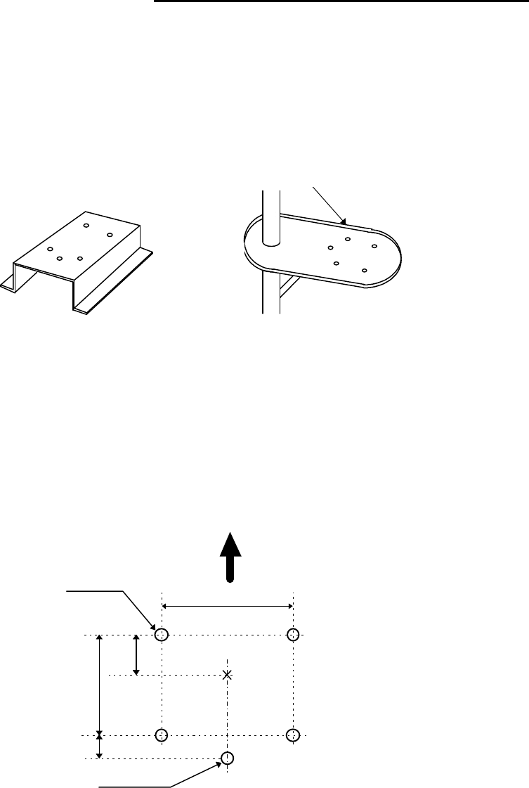
When you have decided the place of installation, install the scanner unit. If a mount base like
the one shown below is available, it may be easier to install the scanner. If such a mount base is
not available in your ship, you may install the scanner directly to the roof, etc. In such a case, pay
attention to the water drain tube located at the bottom of the scanner unit during installation.
Note : When the radar mast or mounting bracket has a curvature of more than 2mm, repair it or
use spacers.
Referring to Fig.3-4, open holes in diameter of 12 mm (0.47 in.) at five locations in the mount
base and use these holes to fix the scanner unit to the mount base with hexagonal bolts. (Use the
template included with this manual.) The bolts included with your radar equipment will suffice
for mount base thickness of 9 to 14 mm (0.35 to 0.55 in.). If the mount base is thicker or thinner
than this, prepare bolts listed in Tab.3-4.
Use sealing of silicon when you prevent the bolts from becoming loose. Radome may be broken
if you use locking putty.
Do not use an edge that might trap water.
Fig.3-3 Mount base
Center
140
140
12φ × 5
60
Forward
(5.51 in.)
(2.36 in.)
(0.47 in.)
30
(1.18in.)
For air tube
(5.51 in.)
Fig.3-4 Hole positions for mounting scanner
15
Tab.3-6 Bolts for Mounting Scanner Unit
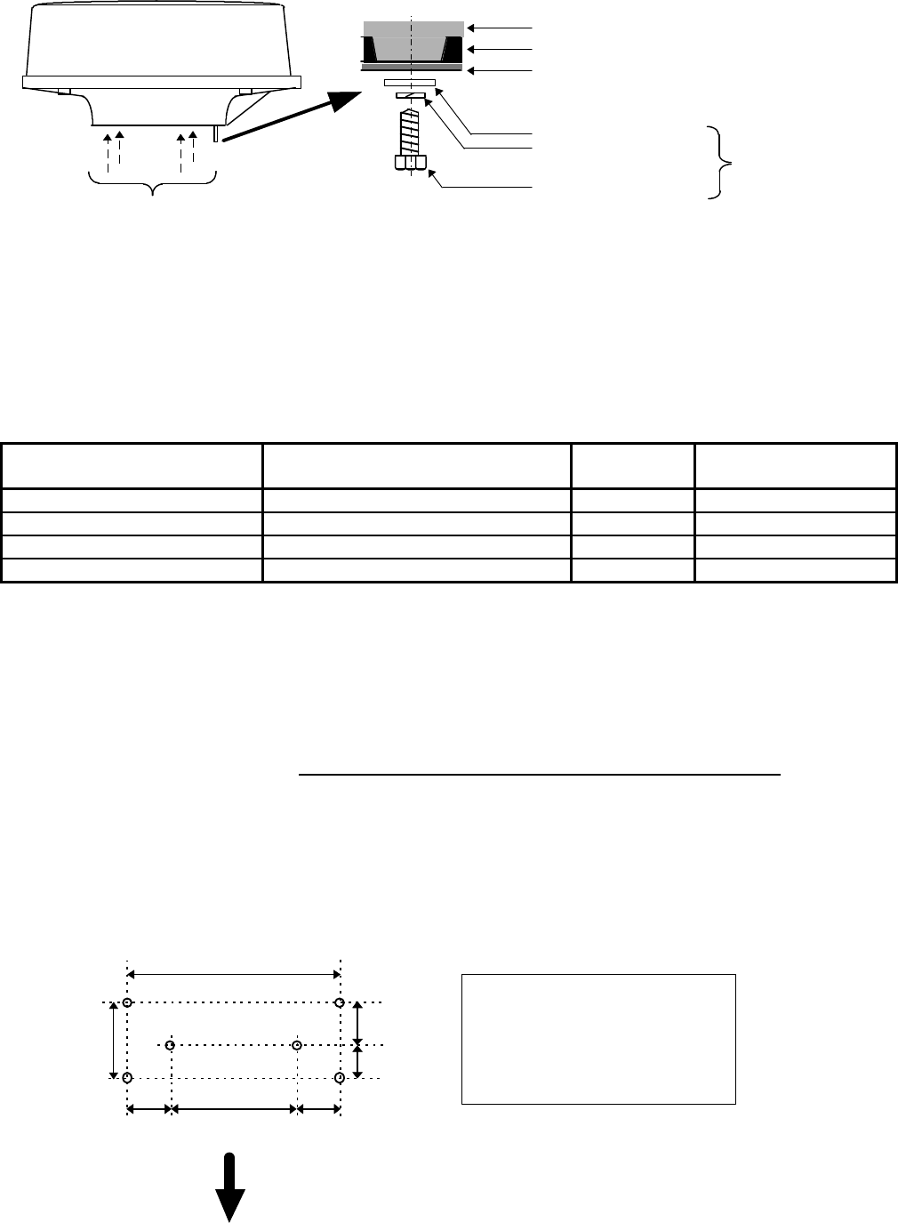
●3.5 Installing Display Unit
After you have finished installing the scanner unit, install the display unit in the same way.
Choose the proper bolt length according to the thickness of the surface on which you are going to
install the display unit. Hole diameter is different using bolts from using tapping screw. When
using tapping screw, open holes in adequate holes. When using bolts and nuts, open holes in di-
ameter of 6 mm (0.24 in.). When you have opened holes, install the pedestal part first and then the
display unit.
Fix four screws
Mount base
Washer
Spring washer
M10 Hexagonal bolt
Radome(bottom)
Chassis
Included
Fig.3-5 Fixing Scanner Unit
Thickness of
mount base Bolts necessary to
fix radome scanner Material Remarks
1-4mm(0.04-0.16 in.) M10 ×
15 (1.5mm pitch) Stainless
4-9mm(0.16-0.35 in.) M10
×
20 (1.5mm pitch) Stainless
9-14mm(0.35-0.55 in.) M10 × 25 (1.5mm pitch) Stainless Included with radar
14-19mm(0.55-0.75 in.) M10
×
30 (1.5mm pitch) Stainless
360
84
Fitting hole
(14.17 in.)
(3.31 in.)
Hole diameter
6mm : Bolts and Nuts
Adequate : Tapping screws
Recommended screw
M5 or equivalent
Unit : mm
47 (1.85 in.)
37 (1.46 in.)
60
(2.36 in.)
240
(9.45 in.)
60
(2.36 in.)
Forward
Fig.3-6 Hole positions for display unit

16
Note : When you install the display by flush mount, refer to appendix "OUTLINE DRAWING".
Slide off four triangle corner cover, and fix the display unit to the panel with screws. After fixing
the display unit, put on corner covers to the corner of the display unit. See APPENDIX.
Avoid a display from operating under direct sun-
light. It becomes high temperature at inside of dis-
play and display may be broken.
!WARNING
17
●3.6 Connecting Cables
Lay cables firmly in place by following the instructions below.
Note1: Do not bind the cable for the radar collectively with cables of other equipment
(especially power supply cable).
Note2: Leave clearance near the inlet of the display so you can remove the display
unit easily. This facilitates installation and maintenance of the display unit.
(Refer to Appendix 1.)
Note3: Because the cable has a connector fitted on the display and scanner side, if it is
necessary to pass cable through a narrow path, fix the scanner-side connector
vertically using vinyl tape before passing cable through the path.
Note4: Lay cable along the ship's hull or wall surface and attach it in place at inter-
vals of about 40 cm.
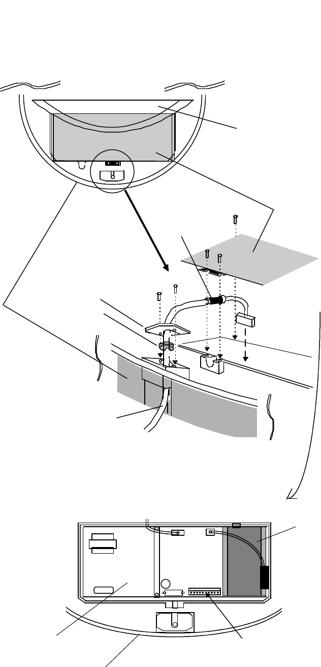
3.6.1 Interconnecting cable (See Fig.3-8)
•Ensure that the radar is off. Connect the cable to the receptacle labeled "SCANNER" on
the rear panel of the display unit.
‚Next, remove the upper part of the radome from the scanner unit. Avoid bumping it
against the antenna by lifting vertically. (There are three fixing screws.)
ƒRemove the tape fixing the antenna.
„Remove the shield cover located on the astern side. (There are three fixing screws.)
…Remove the cable clamping plate and rubber ring, pass cable through the introduction
opening, put the rubber ring from both ends of it, and clamp the cable to the scanner unit
with screws via the fixing plate. Plug the connector fitted to the cable into the X1 connec-
tor on the PCB.
†Replace the aluminum cover. At this time, attach a cable shield onto a ditch with the
aluminum cover. However, be careful that the cable will not be caught up between the
main unit and cover.
‡Replace the upper part of the radome. Be careful not to bump it against the antenna in
the same way as when removing it. Make sure that the cover is fitted in the correct
direction as shown in Fig.3-7. The upper and lower parts of the radome each have three
markings indicating screw positions. Align the upper and lower positions as you mount
the radome.
Fixing screws
Ship's
heading
Logo seal on
side wall
Fig.3-7 Fitting cover
18
Antenna
Stern side Shield cover
Cable shield
Radome (bottom)
Fixing plate
Rubber ring
Interconnecting cable
Fix connector on
PCB(X1)
X1 (Connect here)
Radome (bottom)
PCB
Inner shield
Fig.3-8 Fitting interconnecting cable
19
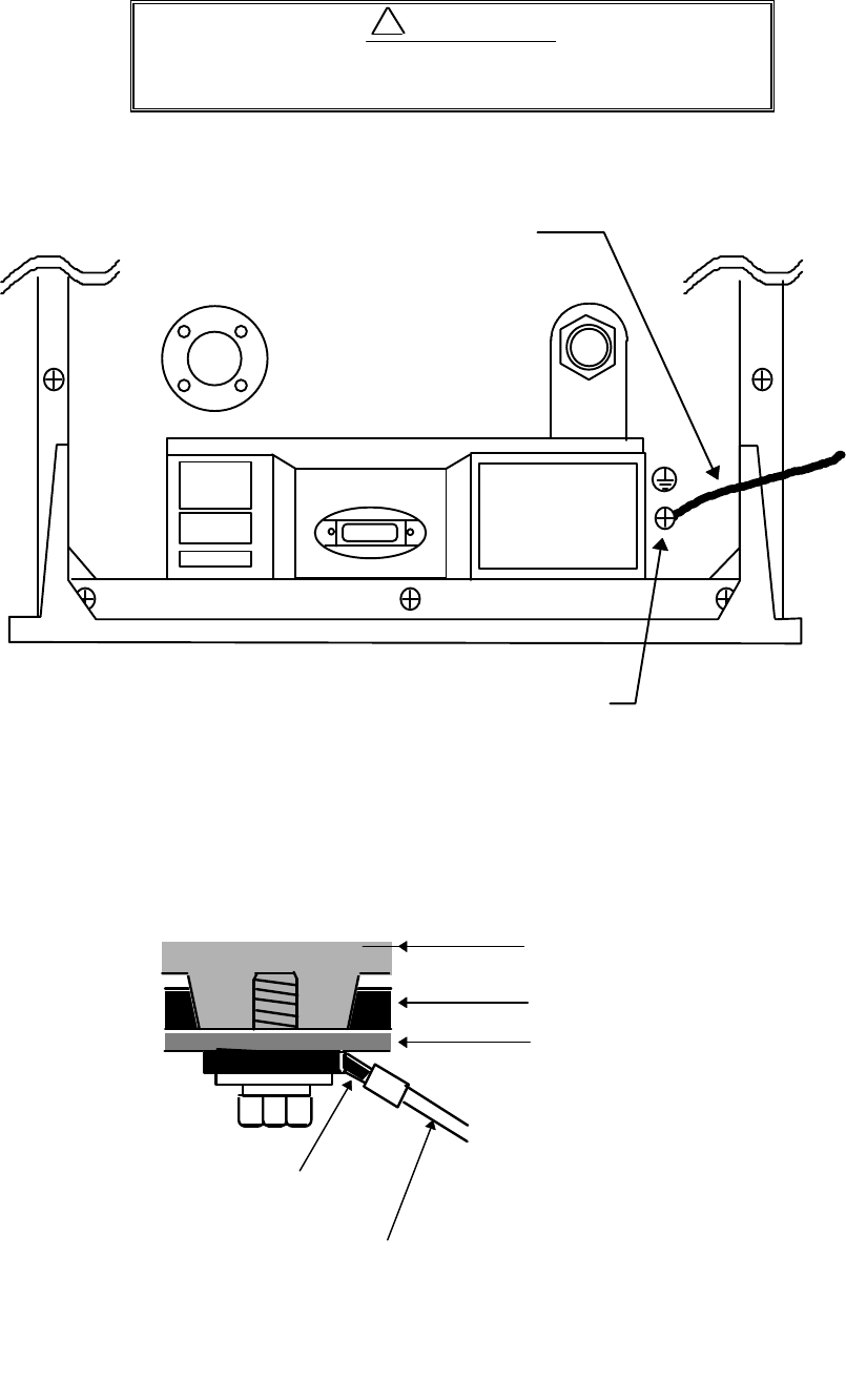
3.6.2 Grounding wire
Connect grounding wire before connecting power
supply cable. Leakage current is too high.
Connect grounding wire from the grounding terminal on the rear panel of the display unit to
the ship's hull as shown below.
Connect grounding wire from one of the bolts you have attached when installing the scanner
unit to the ship's hull as shown in Fig.3-11. (The crimp terminal and grounding wire are not in-
cluded with the radar equipment.)
SCANNER
POWER
OPTION
Grounding terminal
Grounding wire
Fig.3-10 Grounding display unit to earth
Mount base
Radome(bottom)
Chassis
→
To ship's hull
Crimp terminal
Grounding wire
!WARNING
Fig.3-11 Grounding scanner unit to earth
20
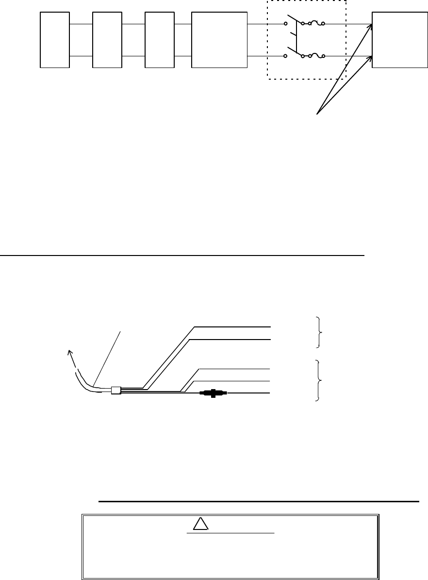
3.6.3 Power supply cable
Power is fed through a knife switch ( or circuit breaker) and protective fuses, as shown in be-
low.
WARNING: Do not apply over 41.6V to Radar
or Radar may be broken.
Fit the power supply cable (included with your radar) to the receptacle labeled "POWER" on
the rear panel of the display unit. And connect to power supply as followings. (When you do not
connect external equipment, put tape on red and green wire.)
Place the Fuse and connection part where there is no water splash and dry area.
When extend the power supply cable, use a suitable cable as below.
Ship's Power Voltage Cable conductor Cable max. length
cross section
12Vdc 3.5 mm23 m
6.0 mm25 m
24Vdc 2.0 mm26 m
3.5 mm210 m
●3.7 Adjustment
Be sure to operate the following adjustment. If this
is not adjusted properly, the radar picture does not
display true image.
White
Black
Gray
Green
Red
Power supply cable
To display unit
DC+
DC-
Ground
NMEA-
NMEA+ To external
equipment
To power supply
Fig.3-12 Power supply cable
!CAUTION
Generator Switchboard Charger Storage
Battery
12/24V
Main switch panel
(Knife Switch with
Fuses)
Radar Display
Unit
DC voltage
reference points
21
When you have finished installing the scanner and display units and connecting cables, turn
on the power to the display and scanner units and check to see if they operate normally without
problem. Then make adjustments as detailed below and check to see if the units operate normally
again.
Heading direction offsets about 60 degree from scanner heading when
shipped from factory. "
‚
HEADING DIRECTION" must be carried out when
install the radar.
• TUNING Refer to Adjusting tuning circuit in 5.5.4.5.4
‚ HEADING DIRECTION Refer to Adjusting angle in 5.5.4.5.4
ƒ DISTANCE Refer to Adjusting distance in 5.5.4.5.4
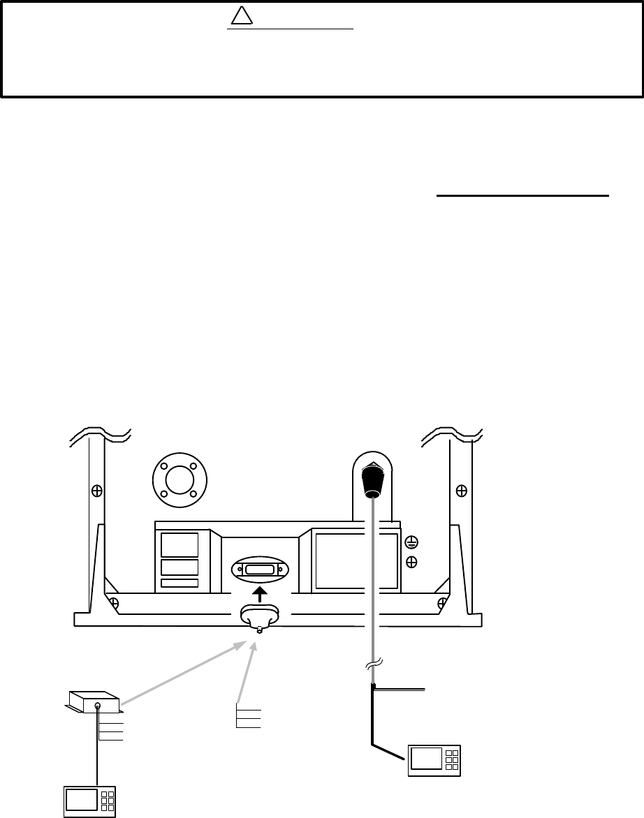
●3.8 Connecting External Equipment to Display Unit
The display unit has two channels of NMEA input. One is standard in power cable. The other
is necessary to connect optional parts (Junction box with OPTION cable).
OPTION connector is located at display’s rear panel for connecting external equipment such
as a GPS, LORAN, or gyro compass. You must have an Junction box with OPTION cable sepa-
rately available from Anritsu. (Refer to CHAPTER 8 (4) External interface.)
Note: SIN/COS and MOB signals cannot be used on Junction Box.
Junction box with OPTION cable (Order No. RZ704A)
SCANNER
POWER
OPTION
OPTION cable
Junction box*note POWER cable
External NMEA equipment
External NMEA equipment
Green :NMEA-
Red :NMEA+
To power supply
Other radar,
slave monitor,
External buzzer,
Gyro I/F
Other radar,
slave monitor,
External buzzer,
Gyro I/F,
SIN/COS.
MOB(NMEA out)
Fig.3-13 Connecting external equipment to display unit
!WARNING
22
●3.9 Countermeasure for Electromagnetic Interference
Anritsu radar provides shields in the units and the inter-unit connection cable. When the ra-
dar, however, is closely installed to radio equipment such as VHF transceiver, UHF transceiver,
etc., or the radar and/or radio equipment are not sufficiently grounded to the hull or ship's earth,
the radar may happen to cause EMI trouble.
Followings are general procedures for reducing EMI due to radars. When installing radars,
refer to them, and also check the radio equipment EMI trouble with operating the radar and radio
equipment.
(1) Installation Place of Radar
The display unit, scanner unit and inter-unit connection cable should be located apart
from the main unit, feeder, antenna coupler and antenna of radio equipment as far as possi-
ble.
Especially, proper installation of the feeder, antenna coupler and antenna of radio equip-
ment is very important to improve EMI trouble.
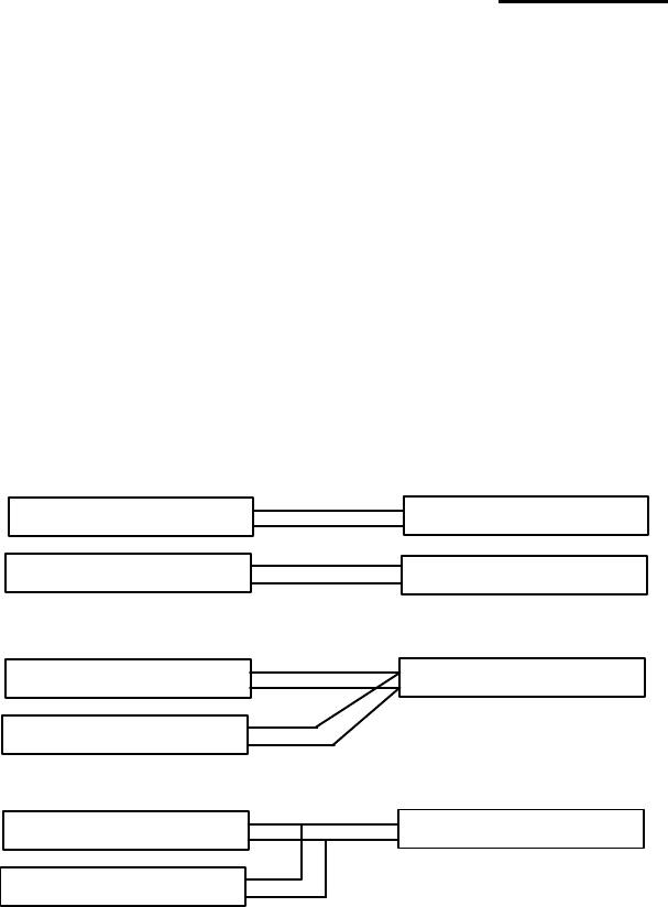
(2) Laying Power Supply Cables
Following connections A and B are recommended to reduce conduction noise generated
from radar. Connection C should not be used.
Connection A
(Very Good)
Connection B
(Good)
Connection C
(Bad)
(3) Grounding
All equipment should be firmly grounded at the earth nearest hull with copper plates or
braided wires.
Improvement Procedure for EMI
(1) Confirm grounding on the radar and radio equipment. However, some equipment, on
which grounding is not always necessarily, have a possibility of EMI improving when tak-
ing off their grounding. Try to take off grounding.
(2) Confirm power supply cable connections and modify to the connection A or B above.
(3) Try to shift the display unit and inter-unit connection cable of radar to be apart from radio
equipment.
(4) Try to shift the feeder of radio equipment to be apart from each units and the inter-unit
connection cable of radar.
(5) Try to shift the antenna coupler and antenna of radio equipment to be apart from the
scanner unit and inter-unit connection cable of radar.
RADAR
RADIO EQUIPMENT
SHIP'S SUPPLY
SHIP'S SUPPLY
RADAR
RADIO EQUIPMENT
SHIP'S SUPPLY
RADAR
RADIO EQUIPMENT
SHIP'S SUPPLY
23
●3.10 When Discarding Your Radar
When discarding your RA775UA radar, consult Anritsu or its distributor to get information
on precautions to be followed. Tab.3-5 below lists the primary component materials of the
RA775UA radar for your reference.
Tab.3-7 Component Materials
Scanner unit Material Display unit Material
Radome
AES
Front panel
ABS
Chassis
A5052P
Rear panel
ADC12
Base
ADC12
Pedestal
ABS+PC
24
CHAPTER 4. FUNCTIONS AND NAMES
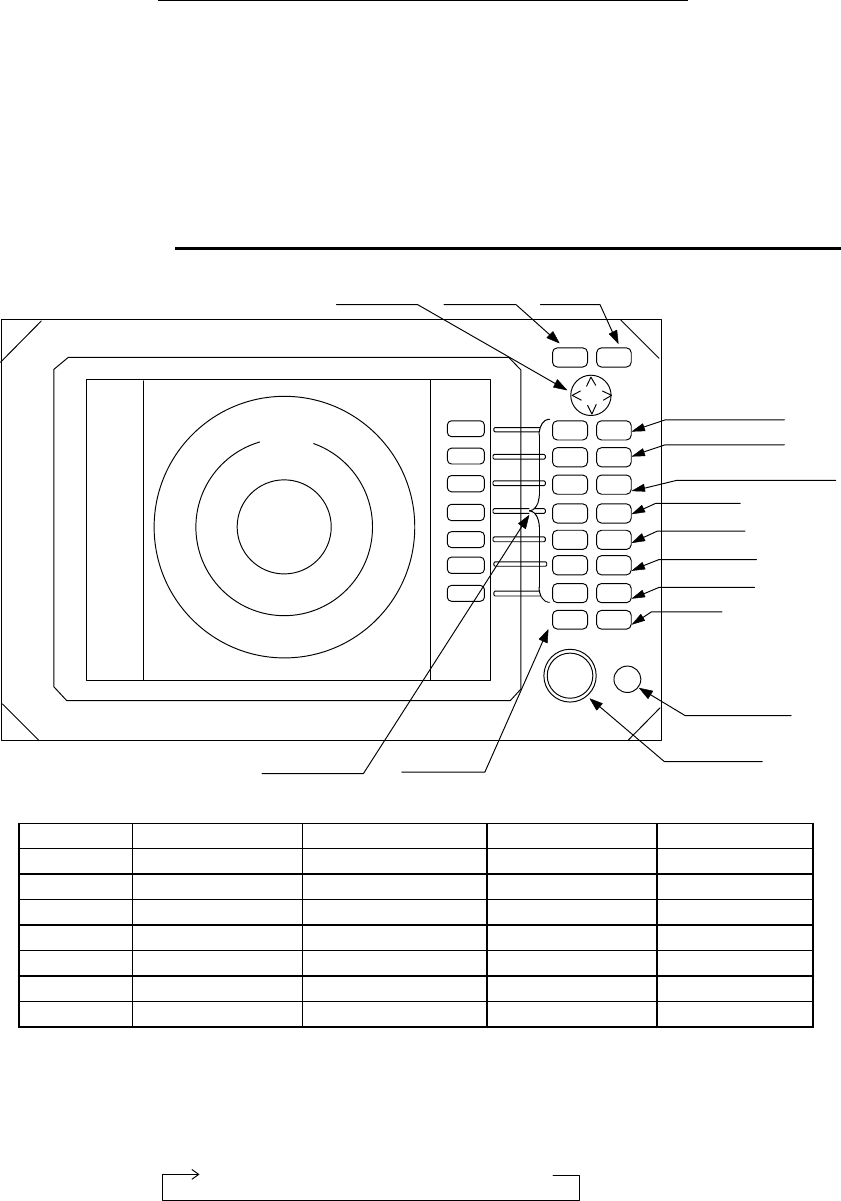
Function and name of each part
The RA775UA radar consists of a display unit to display video images on a screen and a
scanner unit configured with an antenna to radiate radio waves and other components. The
display unit has on its front panel eighteen(18) push-switch keys and one cursor key that lets
you move a cursor in any desired direction. A combination of these keys allows you to utilize
all functions of your radar, providing a comfortable, easy way to operate.
●
4.1 Key layout
Key No. SET1 SET2 SET3 SET4
1 EBL1 EBL2 RINGS PPI
2 VRM1 VRM2 TUNE PPI/3D
3 VAR RNG FL EBL2 ST PPI/PPI
4 TRACK FL VRM2 ZOOM PPI/NAV
5 TARGET GZ SLEEP ALL PPI
6 SEL WIN OFF-C PICTURE ALL PPI2
7 NEXT NEXT NEXT NEXT
Tab. 5 Function of soft key (Factory setting)
*Every time Next key is pressed, soft key group switches as follows.
Cursor key MENU key ENT key
3
1
HU
RANGE
UP
RANGE
DOWN
BRILL
AUTO
GAIN
STC
FTC
MOB
1
2
3
4
5
6
7
POWER
ENTMENU
MOTOR
1:58
+
POWER key
Soft keys(* )
RADAR OFF
Scanner
Motor fuse
Control knob
RANGE Up key
RANGE Down key
BRILL key( Contrast
Brilliance, keys backlight)
AUTO key
GAIN key
STC key
FTC key
MOB key
SET1
→ SET2 → SET3 → SET4
25
●
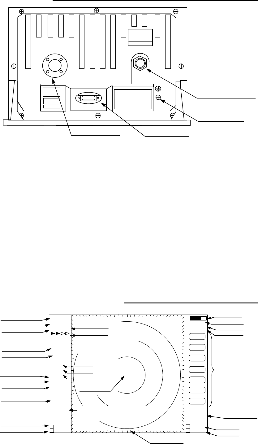
4.2 Rear panel
•
Power supply connector
Use this connector to plug in the power supply cable. Standard NMEA interface
terminal is included in this connector. Refer to Section 3.6 “ Connecting Cables “ and
Section 3.8 “Connecting External Equipment to Display Unit “.
‚
Grounding terminal
Use this terminal to connect grounding wire. Refer to Section 3.6 (3) “Grounding
wire”.
ƒ
Option connector
Use this connector to connect NMEA, an external monitor, external buzzer and GYRO
I/F. A dedicated cable or dedicated module box is required to connect these pieces of
equipment. Refer to Section 3.8 “Connecting External Equipment to Display Unit”.
„
Scanner connector
Use this connector to plug in the inter-connecting cable to connect the scanner unit.
Refer to 3.6 “Connecting cable “.
●
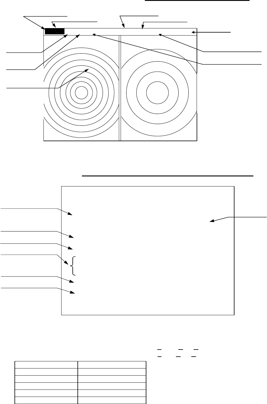
4.3 Radar screen
(
Single screen
)
SCANNER
POWER
OPTION
Ship’s position
EBL2
VRM2
Indicate soft key
3
1
HU L
1:58
+
RADAR OFF
EBL1
VRM1
EBL2
VRM2
FL EBL2
FL
VRM2
NEXT
AHOLD
ZOOM
OFF−C
LAT/LON
35°08.42N
139°02.53E
2 129.8°
2 12.34NM
0.23 NM
HDG
129.0° T
SPD
12.0KT
G59
SAT
FAT
ST1
GZ IN
TK 15S
WP
134.4°
12.5NM
+LAT/LON
35°08.42N
139°02.53E
1 129.8°
1 12.34NM
Tune meter
Picture hold
Zoom
Off-center
Range
Range ring interval
Display mode
Heading angle
Cruising speed
Enlarging echo
Guard zone
Track
Way point
EBL1
VRM1
Pulse width
Course error
Gain
STC
FTC
Cross cursor
Cross cursor position
(LAT/LON or Distance/Bearing)
Bearing scale
•Power supply connector
‚Grounding terminal
„Scanner connector ƒOption connector
26
●
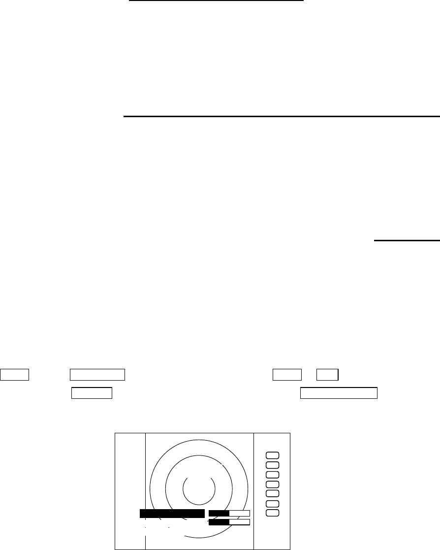
4.4 Radar screen
(
Dual screen
)
ex) PPI/PPI screen
●
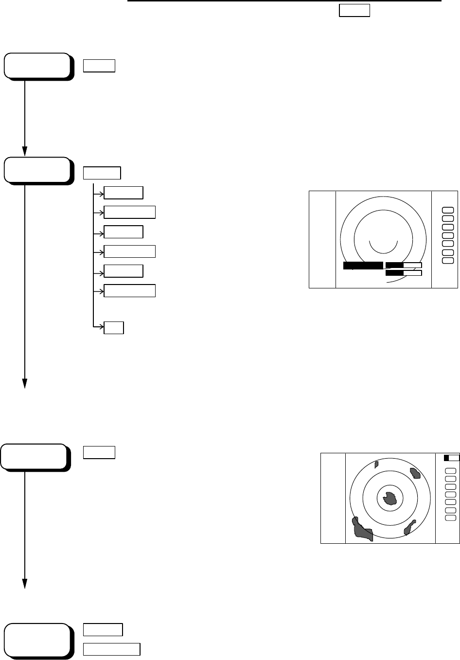
4.5 Radar screen
(
All PPI screen
)
Tune meter
Picture hold
Indicate soft key
SPD 12.8KT GZ R IN WAY P 134.4°
HDG 129.0° GZ L IN 12.5 NM
+MK 38.4° ST1 LAT 35°08.42N 2129.8°
5.28 TK 15S LON 139°02.53E23.62NM
6 1.0 HU L .75 .25
EBL1
VRM1
EBL2
VRM2
FL EBL2
FL
VRM2
NEXT
AHOLD
0.23
XTE >>>
1 129.8°
1 12.34NM
AT1
G 59/AT
S AT/AT
F AT/AT
Range(Left screen) Range(Right screen)
Range ring interval Range ring interval
(Left screen) (Right screen)
Display mode
Pulse width
Cross cursor
Course error
EBL1
VRM1
+
Cruising speed Guard zone(Right screen) Way point
Heading angle Guard zone(Left screen)
Cross coursor position Enlarging echo Ship’s position VRM2
(LAT/LON or Distance/Bearing) Track EBL2
AUTO (Left/Right)
Gain (Left/Right)
STC (Left/Right)
FTC (Left/Right)
3
1
HU L
GZ IN
1:58
+
RADAR OFF
OFF−C
HOLD
ZOOM
Off-center
Picture hold
Zoom
Range
Range ring interval
Display mode
Guard Zone
Pulse width
Cross cursor
27
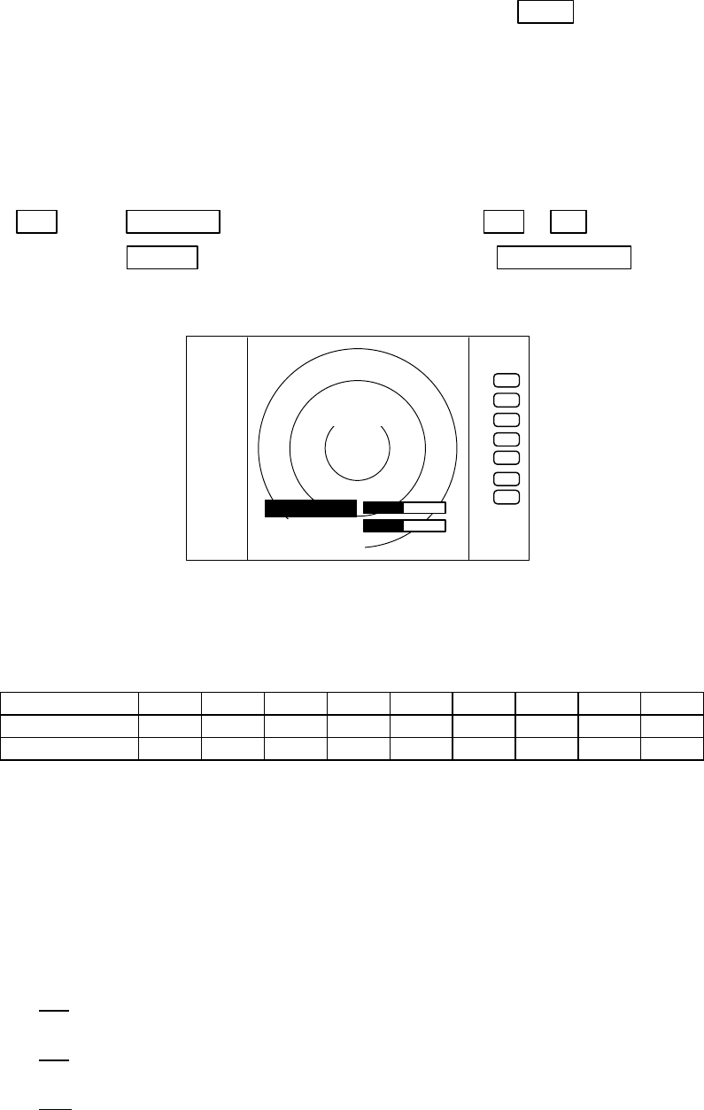
●
4.6 Radar screen
(
All PPI /PPI screen
)
●
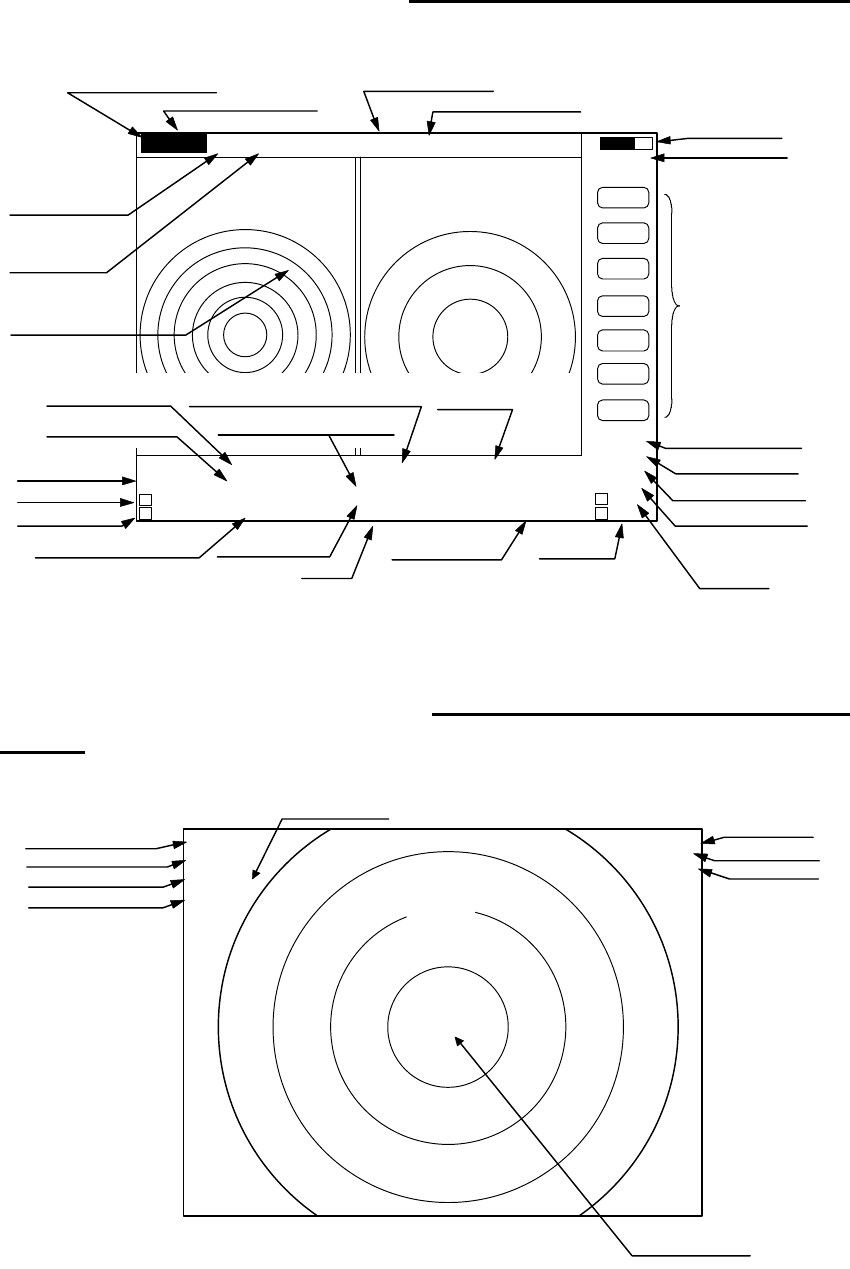
4.7 Navigation screen
It is necessary that navigation equipment such as a GPS is connected to your radar, this
screen displays the position and cruising speed of your ship, seawater temperature, and other
navigation information.
Note: Heading angle will be displayed "COG" when Course Over Ground data is used.
Note: Cruising speed will be displayed "SOG" when Speed Over Ground data is used.
>
Indicates starboarding the helm
(right)
<
Indicates porting the helm (left)
Picture hold
Gurad zone(Right screen)
Guard zone(Left screen)
6 1.0 HU L GZ IN .75 .25 GZ IN HOLD
Range(Left screen) Range(Right screen)
Range ring interval Range ring interval
(Left screen) (Right screen)
+
Display mode
Pulse width
Cross cursor
NAV DISPLAY
WP 134.4°COURSE
12.5
NM
>>>
HDG 129.0°0.23
NM
SPD 12.8
KT
LAT 35°08.42N
LON 139.02.53E
TEMP 20.5°
C
DEPTH 93.2
M
ST
’
BY
Way point
Heading angle
Cruising speed
Current position
Sea water temperature
Depth of water
Course error
Deviation from course
Indication mark
0.00 --
><
0.02 --
>
or
<
0.04 --
>>
or
<<
0.08 --
>>>
or
<<<
0.16 --
>>>>
or
<<<<
Tab.6 Indication of deviation from course
28
CHAPTER 5. OPERATION
Basic operation of radar
The RA775UA radar has several fixed-function keys on the front panel. These functions can be
controlled by simply pressing the key. Also, special functions can be customized to soft-keys by
user-setting. The followings explain the operation of each keys.
5.1 Powering On and Off
(1) Powering On
Press the "POWER" key. Buzzer sounds "pi" and starts the radar system.
Screen contrast and brilliance is set to the level that of the radar system was power off.
(2) Powering off
Keep pressing the "POWER" key more than 3 seconds, then the radar system will power off.
5.2 Adjusting contrast and brilliance of the screen, and key-backlight
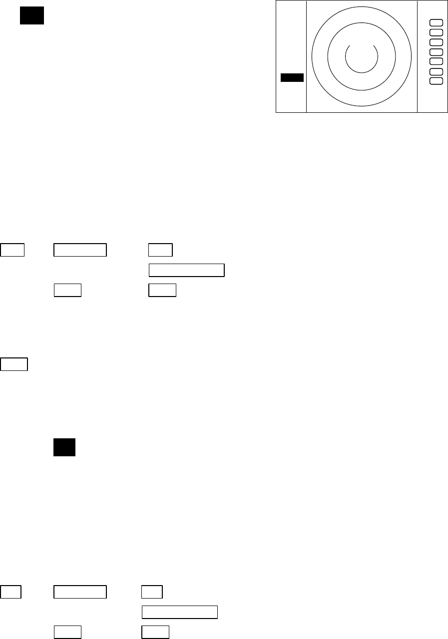
(1) Press the "BRILL" key. (Bar indicating contrast, brilliance, and key-backlight appears on
the screen.)
(2) Adjust each items with the control knob. Items can be selected by up-down cursor.
(3) When the adjustment is finished, press either the "BRILL" key or the "ENT" key to exit from
the adjustment screen. (Pressing some other key after adjustment will lead to the function of the
pressed key.)
BRILL ―> Control knob (Adjustment of contrast) ――> BRILL or ENT
└> Up/Down (Selection of brilliance, key-backlight) └->Other function key Move to other
functions
.75
.25
HU
BRILLIANCE 50
CONTRAST 50
ST’BY
+
KEY BACKLIGHT 4
29
●
5.3 Basic Operations
××× = keys to press
5.3.1 Powering On and Off
POWER
Press "POWER"key to power on.
2 minutes timer and "RADAR OFF" are displayed.
Keep pressing "POWER" key to power off.
Press the "BRIL" key.
BRILL
Control bars are indicated on the screen.
contrast Up/Down Select contrast.
Control knob Adjust contrast with knob.
brilliance Up/Down Select brilliance.
Control knob Adjust brilliance with knob.
key backlight Up/Down Select key backlight.
Control knob Adjust key backlight with
knob.
ENT Press "ENT"key to return.
Radar turn into "ST'BY"mode when 2 minutes timer is finished and
"ST'BY"displayed.
5.3.2 Transmitting
POWER
Press "POWER" key to op-
erate, radar picture appears
on the screen.
Another press "POWER" key,
radar turn to stand-by mode.
Keep pressing "POWER" key
more than 3 seconds, radar turn to power off.
RANG UP
or
Pressing "RANGE UP" key produces a long-distance range,
RANGE DOWN
"RANGE DOWN" key a short-distance range.
.75
.25
HU
BRILLIAMCE 50
CONTRAST 50
1:58
RADAR OFF
+
KEY BACKLIGNT 4
AT
.75
.25
HU
+
SCREEN
POWER ON
START
CHANGE
RANGE
30
5.3.3 Adjusting contrast and brilliance of the screen, and key-backlight
××× = keys to press
(1) Press the "BRIL" key. (Bar indicating contrast, brightness, and panel appears on the screen.)
(2) Select contrast, brilliance, or key backlight with the up-down cursor.
(3) Adjust each item with the control knob.
(4) When the adjustment is finished, press either the "BRIL" key or the "ENT" key to exit from
the adjustment screen. (Pressing some other key after adjustment will lead to the function of the
pressed key.)
BRIL ――> Control knob (Adjustment of contrast) ――> BRIL or ENT
└-> Up/Down (Adjustment of brightness, panel)└-> Other function key Shift to other func-
tions
5.3.4 Changing Distance Range (RANGE UP, RANGE DOWN)
Pressing "RANGE UP" key produces a long-distance range, and "RANGE DOWN" key a
short-distance range.
RANGE 0.125 0.25 0.5 0.75 1.5 3 6 12 24
Number of rings 222366666
Range ring interval 0.0625 0.125 0.25 0.25 0.25 0.5 1 2 4
5.3.5 Automatic adjustment (AUTO)
AUTO adjusts the GAIN, STC and FTC automatically.
If the "AUTO" key is pressed while GAIN, STC, or FTC are under manual settings, they will all
be switched to AUTO or HBR(HARBOR) mode.
Pressing "AUTO" key, AT1, AT2 and HBR changes alternately. Pressing STC key, all controls return
to manual state.
AT1
Use when find navigation way in much echo such as port area, narrow channel, small
islands area. The control condition is similar to less STC, slightly down GAIN.
AT2
Use at open sea to suppress the sea clutter. The control condition is similar to high
STC, high GAIN.
HBR
Use at in a bay area, inlet, or a harbor. The control condition becomes manual STC by
using the value established HARBOR of ADJUST menu.
Note) Refer to “Setting HARBOR STC circuit(HARBOR)” in section 5.5.4.5.4(7).
Note) When you select HBR mode, FTC will be switched to MANU mode.
* What happens if GAIN, STC, and FTC keys are pressed during AUTO operation?
1) If GAIN key is pressed, Only GAIN enters a manual state.
2) If FTC key is pressed, Only FTC enters manual state.
.75
.25
HU
BRILLIANCE 50
CONTRAST 50
ST‘BY
+
KEY BACKLIGNT 4
31
3) If STC key is pressed, STC, GAIN, and FTC enter manual state.
5.3.6 Sensitivity adjustment (GAIN)
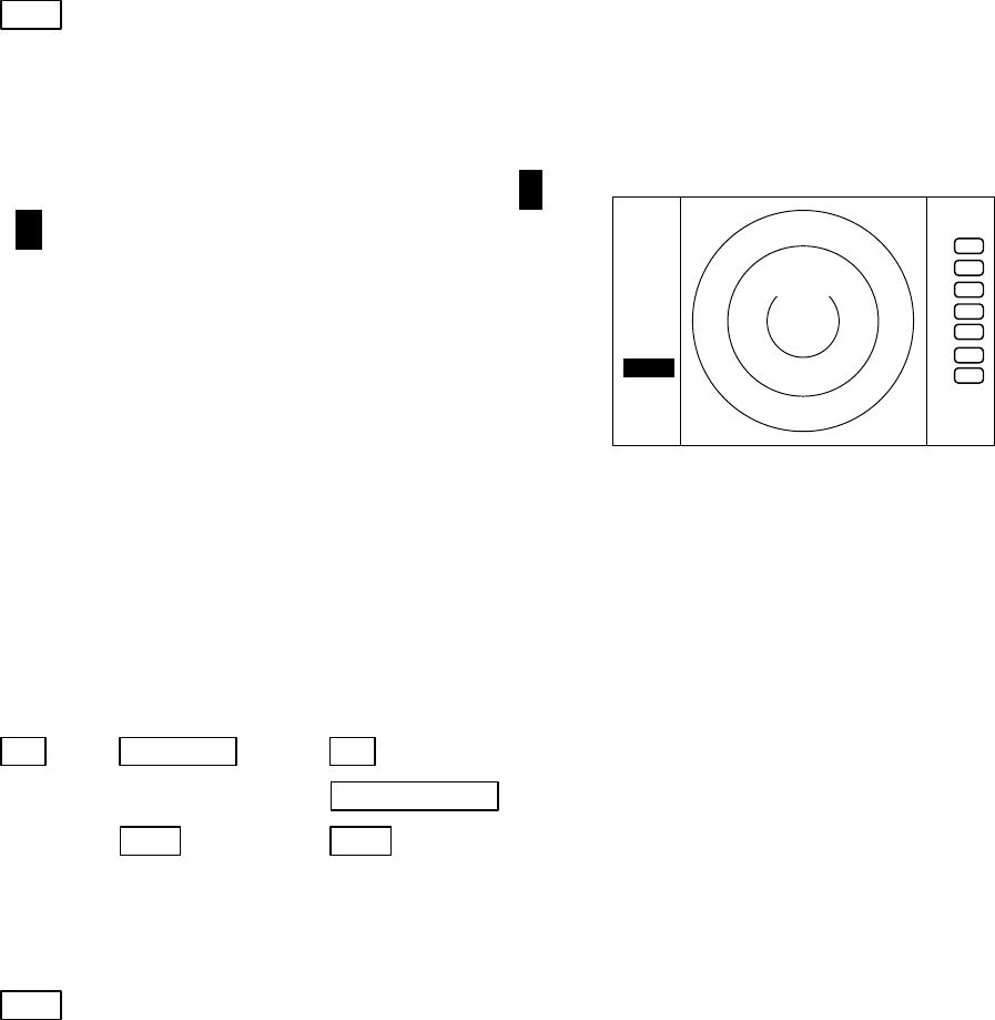
(1) When the "GAIN" key is pressed, the GAIN dis-
play on the left side of the screen will be reversed
as
G 35
and the adjustable state will be entered.
(2) When the control knob is turned, the figure will be
shifted within a range of 0 and 99, and the sen-
sitivity can be manually adjusted. When the
"AUTO" key is pressed, all (GAIN, STC and FTC)
will enter an AUTO state.
(3) After the adjustment is finished, press the "GAIN"
key to exit from the adjustment state. If some
other function key is pressed, shift to that function
will take place.
(a) To make adjustments by MANUAL (When the GAIN key is pressed under AUTO operation,
shift to a manual operation will take place.)
GAIN ―> Control knob ―> GAIN --------------- The adjustment state is ended.
| └> Other function key --- Shift to other functions
└> AUTO └> AUTO ---------------- GAIN, STC, and FTC are set at AUTO and the
adjustment state is ended.
(b) To switch from the MANUAL state
AUTO ----------------------------------------------- Set GAIN, STC and FTC at AUTO
5.3.7 Removing sea clutter (STC)
(1) When the "STC" key is pressed, the STC display on the left side of the screen will be re-
versed as
S 35
and the adjustable state will be entered.
(2) When the control knob is turned, the figure will be shifted within a range of 0 and 99, and
the STC can be manually adjusted. When the "AUTO" key is pressed, all (GAIN, STC and
FTC) will enter an AUTO state.
(3) After the adjustment is finished, press the "STC" key to exit from the adjustment state. If
some other function key is pressed, shift to that function will take place.
(a) To make adjustments by MANUAL (When the STC key is pressed under AUTO operation, shift
to a manual operation will take place.)
STC ―> Control knob ―> STC ----------------- The adjustment state is ended.
| └> Other function key ----- Shift to other functions
└> AUTO └> AUTO ----------------- STC, GAIN, and FTC are set at AUTO and the
adjustment state is ended.
.75
.25
HU
G 50
ST‘B
+
32
NOTE) When you select MANU mode, GAIN and FTC will be switched to MANU mode, too.
(b) To switch from the MANUAL state
AUTO ----------------------------------------------- Set STC, GAIN and FTC at AUTO
5.3.8 Removing rain and snow clutter (FTC)
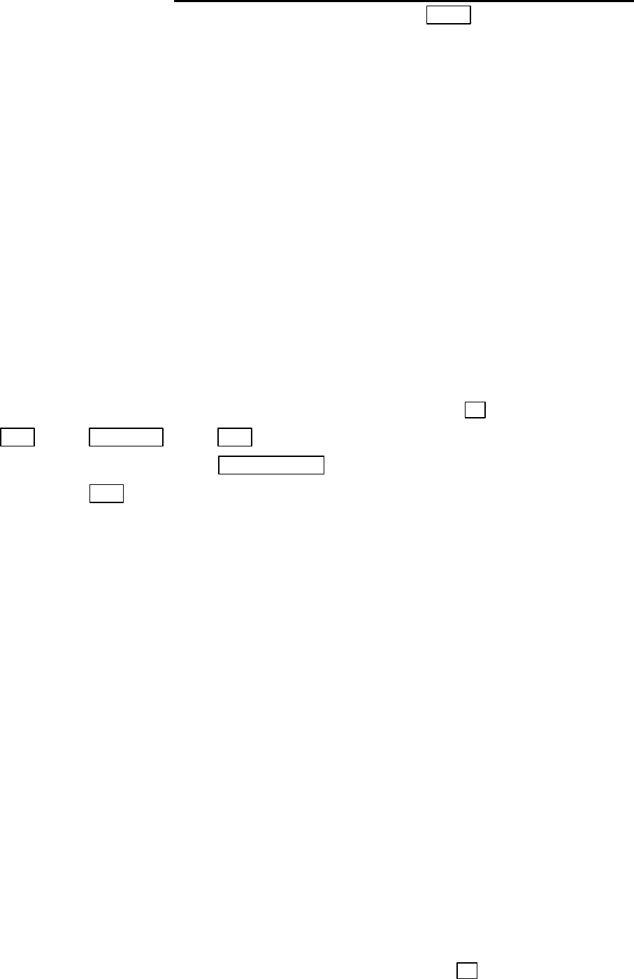
(1) When the "FTC" key is pressed, the FTC display
on the left side of the screen will be reversed as
F
500
and the adjustable state will be entered.
(2) When the control knob is turned, the figure will be
shifted within a range of 0 and 99, and the sen-
sitivity can be manually adjusted. When the
"AUTO" key is pressed, all (GAIN, STC and FTC)
will enter an AUTO state.
(3) After the adjustment is finished, press the "FTC"
key to exit from the adjustment state. If some
other function key is pressed, shift to that function
will take place.
(a) To make adjustments by MANUAL (When the FTC key is pressed under AUTO operation, shift
to a manual operation will take place.)
FTC ―> Control knob ―> FTC --------------- The adjustment state is ended.
| └> Other function key --- Shift to other functions
└> AUTO └> AUTO ---------------- GAIN, STC, and FTC are set at AUTO and the
adjustment state is ended.
(b) To switch from the MANUAL state
AUTO ----------------------------------------------- Set GAIN, STC and FTC at AUTO
5.3.9 Man Over Board (MOB)
Pressing the MOB key will send the own ship's position data to the external equipment
through NMEA port with "WPL" format. There is no change on the screen.
To check the MOB position data, select "MOB" from the "WINDOW" menu in the "SETUP".
The position of MOB and current position will be displayed on the screen. If press the "MOB" key
while watching the MOB screen, MOB data will be cleared and return to previous screen. If press
other keys, MOB data will be remained and return to previous screen.
.75
.25
HU
F 50
ST‘B
+
33
●
5.4 Functions of Soft Keys
××× = keys to press
・
Outline of soft keys
Any function can be optionally allocated to the key upon which numbers 1-7 are indicated. A
maximum of 4 groups of functions can be allocated to each soft key, and switching between those
functions is conducted by the "NEXT" key.
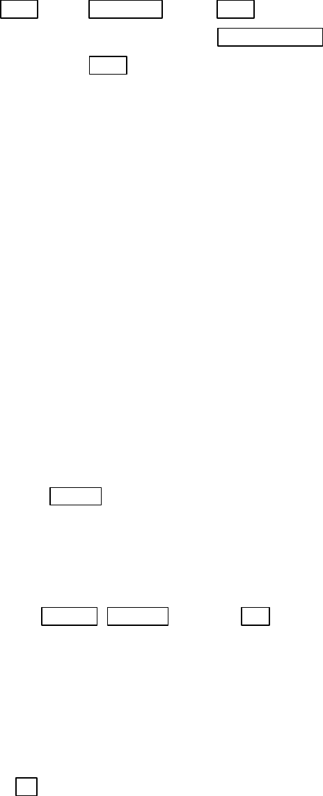
5.4.1 Bearing measurement (EBL1)
(a) Bearing measurement by EBL1
(1) When "EBL1" key is pressed, electric bearing line (EBL1) appears and the angle from the
direction of the ship’s head which is set at 0 °will appear in a reverse display at the lower left of
the screen(Note).
(2) Use the control knob to place the direction cursor on the target, and read the angle.
(3) After the setting
i) If "EBL1" key is pressed, the setting is completed.
ii) If "other function" key is pressed, the function will be shifted to that of the pressed key with
the setting condition still in effect. note: 1 xxx.x ° indicates EBL1.
EBL1 ―> Control knob ―> EBL1 EBL1 is displayed and the process is finished.
|└> Other function key EBL1 is displayed and the function is shifted.
└-> EBL1 EBL1 is turned off.(b)
(b) To turn off the EBL1
When the "EBL1" key is pressed twice, EBL1 disappears. (EBL1 OFF)
Note: Please refer to "5.5.1.1 Bearing measurement (EBL1)".
5.4.2 Bearing measurement (EBL2)
The operation is the same as EBL1, please refer to EBL1 operation. The "EBL2" will appear in
a reverse display at the lower right of the screen
5.4.3 Distance measurement (VRM1)
(a) Distance measurement by VRM1
(1) When "VRM1" key is pressed, variable range maker (VRM1) appears and the distance in a
reverse display appears at the lower left of the screen.
(2) Place the marker on the front edge of the target with the control knob and read the distance.
(3) After the setting
i) If "VRM1" key is pressed, the setting is completed.
ii) If "other function" key is pressed, the function will be shifted to that of the pressed key with the
setting condition still in effect. note: 1 xxx.x NM indicates VRM1.
34
VRM1 ―> Control knob ―> VRM1 VRM1 is displayed and the process is finished.
|└> Other function key VRM1 is displayed and the function is shifted.
└> VRM1 VRM1 is turned off.(b)
(b) To turn off the VRM1
When the "VRM1" key is pressed twice, VRM1 disappears. (VRM1 OFF)
Note: Please refer to "5.5.1.2 Determining the distance (VRM1)".
5.4.4 Distance measurement (VRM2)
The operation is the same as VRM1, please refer to VRM1 operation. The "VRM2" will appear
in a reverse display at the lower right of the screen
5.4.5 Measuring the angle between two points (FL EBL2)
Note: VRM2 and EBL2 do not follow the OFF-C function while floating.
Note: Please refer to "5.5.1.5 Measuring the distance or angle between two points ( FL EBL2,
FL VRM2 )".
(a) Setting a reference point for measurement of the angle.
(1) Press "FL EBL2" key. “SET START POINT” is displayed and a small cross mark appears.
FL EBL2 −> FL EBL2 is turned ON and
(Select FL EBL2) the small cross mark appears.
(2) Use the left-right and up-down cursor keys to place the small cross mark on one of the two
echoes whose angle will be measured, and press the "ENT" key.
Up/Down &Left/Right −> ---- ENT Criterion of the reference point is set.
(Place the cross cursor on an echo)
(b). Measuring
Perform the operations in the above mentioned and "measuring the angle(EBL2)", and place
the EBL2 on another echo.
EBL2 is displayed on the screen based on the placed fixed cross cursor.
" 2 xxx.x°" which is displayed at the lower right will be the angle between the two points.
5.4.6 Measuring the distance between two points (FL VRM2)
Note: Please refer to "5.5.1.5 Measuring the distance or angle between two points ( FL EBL2,
FL VRM2 )".
(a) Setting a reference point for measurement of the angle.
(1) Press "FL VRM2" key. “SET START POINT” is displayed and a small cross mark appears.
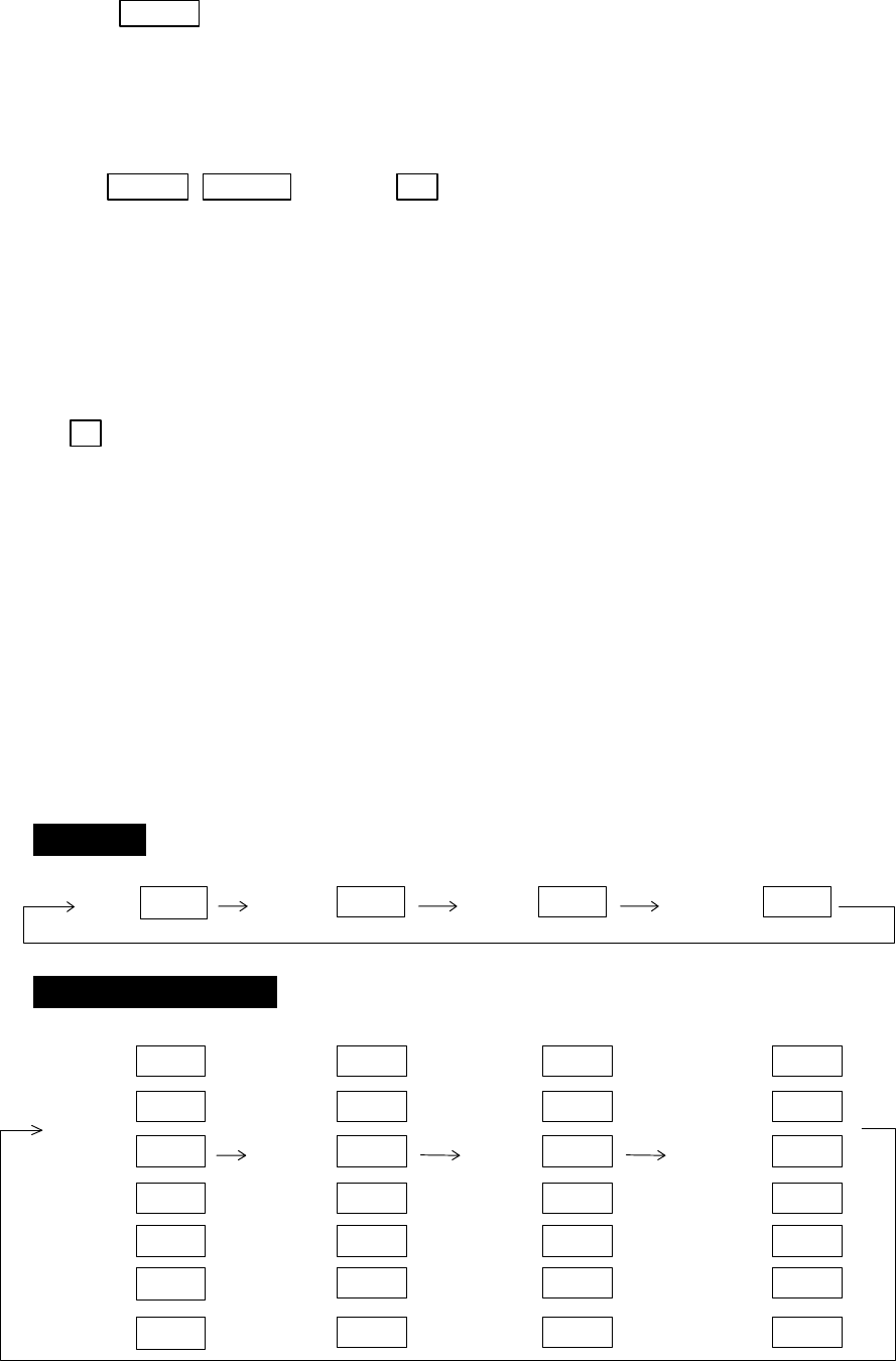
35
FL VRM2 −> FL VRM2 is turned ON and
(Select FL VRM2) the small cross mark appears.
(2) Use the left-right and up-down cursor keys to place the small cross mark on one of the two
echoes whose angle will be measured, and press the "ENT" key.
Up/Down &Left/Right −> ---- ENT Criterion of the reference point is set.
(Place the cross cursor on an echo)
(b) Measuring
Perform the operations in the above mentioned and "measuring the distance(VRM2)", and
place the VRM2 on another echo.
VRM2 is displayed on the screen based on the placed fixed cross cursor.
" 2 xx. xNM" which is displayed at the lower right will be the distance between the two
points.
5.4.7 Changing the group of Soft Keys (NEXT)
Any function can be optionally allocated to the key upon which numbers 1-7 are indicated. A
maximum of 4 groups of functions can be allocated to each soft key, and switching between those
functions is conducted by the "NEXT" key.
The "NEXT" key switches between allocated function groups on the soft key which numbers 1-7
are indicated.
Every time pressing the "NEXT" key, function groups changes to another groups included pressing
"NEXT" key. The function groups can also be changed at the "KEY ASSIGNMENT" function in the
"CUSTOM" menu of the "SETUP" with left-right cursor key.
Operation
Soft Key Setting Example
SET1 SET2 SET3 SET4
The function can be changed at the "KEY ASSIGNMENT" function in the
"CUSTOM" menu of the "SETUP".
7 7 7
NEXT NEXT NEXT 7
NEXT
1
3
4
5
2
1
3
4
5
2
1
3
4
5
2
6 6 6
EBL1
VAR RNG
TRACK
TARGET
VRM1
EBL2
FL EBL2
FL
GZ
VRM2
RINGS
ST
ZOOM
SLEEP
TUNE
SEL WIN OFF-C PICTURE
7 7 6
NEXT NEXT NEXT
1
3
4
5
2
6
PPI
PPI/PPI
PPI/NAV
ALL PPI
PPI/3D
ALL PPI2
6
NEXT

36
5.4.8 Erasing heading maker temporarily (HDG OFF)
Press the “HDG OFF” key. The heading maker is not displayed as long as you hold it down.
5.4.9 Using parallel cursors (///CSR)
Press the “///CSR” key. Parallel cursors will appear on the screen. As you move EBL, the parallel
cursors also move.
To cancel the "///CSR" function, press "///CSR" key once more.
Note: Please refer to "5.5.1.8 Using parallel cursors (///CSR)".
5.4.10 Establishment of the indication of the RANGE RINGS (RINGS)
Press the “RINGS” key. Range Rings will appear on the screen. To cancel the "RINGS" function,
press "RINGS" key once more.
Note: Please refer to "5.5.1.9 Establishment of the indication of the RANGE RINGS (RINGS)".
5.4.11 ON/OFF of variable range function (VAR RNG)
Usually the range changes in steps as 0.5--0.75--1.5--3.0--....., but using this function will enable a
consecutive change such as 0.5--0.6--0.7--0.8--..... .
Press the “VAR RNG” key. The VAR RNG function becomes valid and VAR will be displayed
at the upper left of the screen (beside MODE). To cancel the "VAR RNG" function, press "VAR RNG"
key once more.
The range changes continuously with the up-down cursor while the VAR RNG function is on, and
it changes in steps with the "RANGE UP" or "RANGE DOWN" keys.
If pressing other keys, return to the normal state from continuously range change state.
5.4.12 Changing display modes (MODE)
(1) Select MODE from the pull-down display items using the up-down cursor keys, and press the
"ENT" key.
(2) When the HU/HS/NU/CU/TM sign is displayed beside the MODE item, select display mode with
the up-down cursor keys and press the "ENT" key.
(3) The setting will be completed when the "ENT" key is pressed after the selection. (NOTE1,2)
Press the "MODE" key, the display mode will change on every pressing to HU, HS, NU, CU, TM in
order. The mode select at the upper of the screen is indicated. However, a setting will be needed for the
ship’s speed if TM is selected. Also, a heading or a course information is necessary for NU, CU and TM.
note: TM is valid only on PPI screen. The mode will change to NU on the other screen automatically.
Note: Please refer to "5.5.2.1 Changing display mode (MODE)".
5.4.13 Guard Zone (GZ)
A function that sets a guard zone of any distance and any angle range, creating alarm tone when
either echoes above a certain level exist (IN MODE) or no echoes exist(OUT MODE).

37
When GZ is operated with soft keys, guard zone settings and ON/OFF settings can be conducted,
but the mode (IN or OUT) is to be set in the menu.
Note: Please refer to "5.5.2.2 Guard Zone (GZ)".
(1) When the "GZ" key is pressed, the present mode setting will be displayed on the left side of the
screen as GZ IN. A small cross cursor for setting the guard zone will be displayed at the screen
center while "SET CENTER POINT" is displayed at the bottom, activating a guard zone setting
state.
(2) Use the up-down/left-right cursor keys to move the cross cursor to the center of the warning zone
to be set, and press the "ENT" key.
(3) From the cross cursor position set in (2) above as the center, expand the guard zone in the
direction of the distance with the up cursor key and in the direction of the angle with the right
cursor key, thus making the form of a fan. To make the warning zone smaller, operate the down
cursor key (in the direction of the distance) and the left cursor key (in the direction of the angle).
(4) After the setting the guard zone, finish by pressing the "ENT" key.
Press the GZ key twice to cancel the guard zone function.
GZ −> Up/Down &Left/Right −> ENT −> Up/Down &Left/Right −> ENT Setting completed
|(Setting the center of GZ) (Setting the scope of GZ)
└> GZ ---------------------------------------------------------------------Canceling GZ
・
Stop the alarm tone
Press the "MENU" key or "ENT" key during the alram tone sounds, alarm tone will stop.
note: Set the mode (IN or OUT) at the "GZ MODE" of the "PRESET2" function in the "CUSTOM"
menu of the "SETUP"
Set the alarm level (IN or OUT) at the "GZ LVL" of the "PRESET2" function in the "CUSTOM"
menu of the "SETUP"
5.4.14 Off Center (OFF-C)
Displaying the location specified by the cross cursor as the ship's location
Note: Please refer to "5.5.2.3 Shifting display in specific direction (OFF-C)".
(1) When the "OFF-C" key is pressed, OFF-C is displayed at the upper right and "SET OFF CENTER
POINT" at the bottom of the screen, and setting is ready to be entered.
(2) Move the cross cursor with the cursor keys to move the ship to the intended location, and press
the "ENT" key. The ship's location will be displayed as the cursor's location. OFF-C is displayed
at the upper right , which indicates that the "OFF-C" state is entered.
(3) To cancel "OFF-C" function, press the "OFF-C" key.
(a) To conduct the setting
OFF-C −> Up/Down & Left/Right −> ENT --------Conduct Off Center to exit the adjustment state.
Note: VRM2 and EBL2 do not follow the OFF-C function while floating.
The function operate on PPI screen only.
(b) To cancel the setting
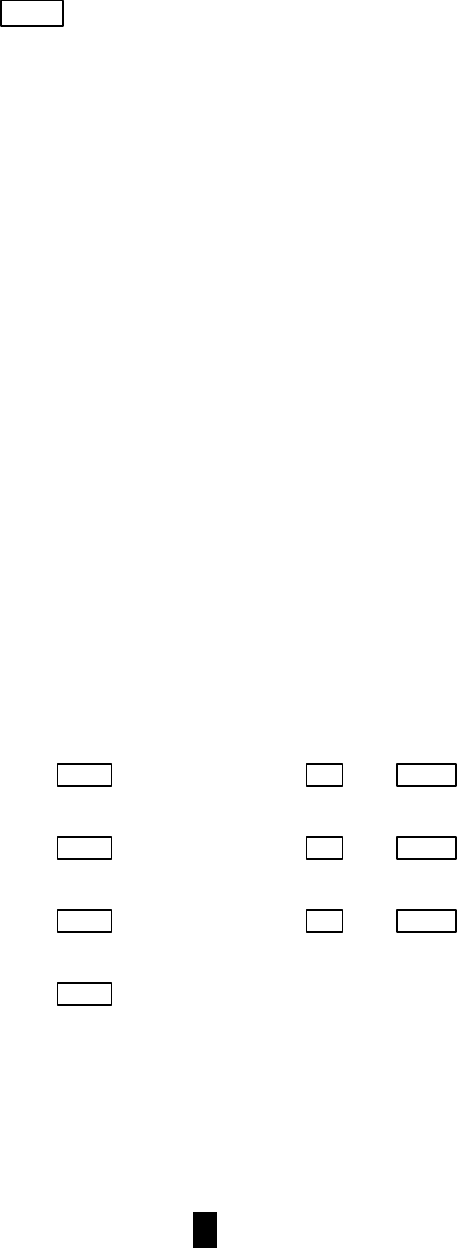
38
OFF-C -----------------------------------The "OFF-C" display at the upper right disappears and function
returns to the ordinary state from the Off Center state.
5.4.15 Setting of the SLEEP function(SLEEP)
This function sends a 30-second-transmissions during pre-fixed hours. After a transmission, a
power-saving mode is entered with the screen in ST'BY state (the scanner-OFF state) and the LCD
backlight turned off. This action is repeatedly executed.
Usage example, set a guard zone and have the warning signal automatically confirmed every
prefixed period.
Press the "SLEEP" key. Every pressing the key, "SLEEP" function will be set as 5-minutes, 10-
minutes, 15-minutes, or off.
When a transmission is conducted after setting a SLEEP mode, a ST'BY state is entered and the
backlight turns off after a 30-second-transmission. (Power-saving mode). Two minutes before the
fixed time the backlight turns on and the 2-minute timer starts. Then, at the fixed time another 30-
second-transmission begins. This series of actions are repeated. If any one key is pressed during the
course of this action, the SLEEP function will be canceled.
Note: Please refer to "5.5.2.4 Setting of the SLEEP function(SLEEP)".
(1) Setting procedure
SLEEP ->(Select 5min.) → ENT →POWER -> 30-second-transmission every 5 min.
└ transmission ON
SLEEP ->(Select 10min.) → ENT → POWER -> 30-second-transmission every 10 min.
└ transmission ON
SLEEP ->(Select 15min.) → ENT → POWER -> 30-second-transmission every 15 min.
└ transmission ON
SLEEP ->(Select OFF) --------------------------------------- SLEEP function is turned OFF
Setting completed
5.4.16 Tuning adjustment (TUNE)
(1) When the "TUNE" key is pressed, the TUNE display on the upper-right side of the screen
will be reversed as
35
and the adjustable state will be entered.
(2) When the control knob is turned, the figure will be shifted within a range of 0 and 99,
and the receiver tuning can be manually adjusted.
(3) After the adjustment is finished, press the "ENT" key to exit from the adjustment state.
If some other function key is pressed, shift to that function will take place.
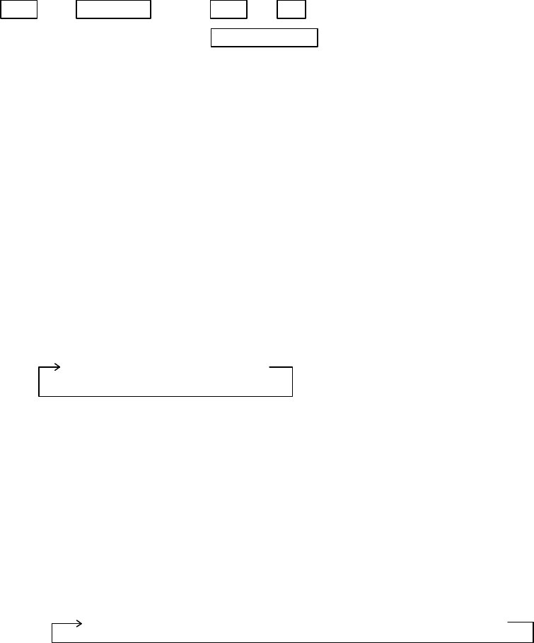
39
TUNE ―> Control knob ―> TUNE or ENT ------- The adjustment state is ended.
(tuning adjustment) └> Other function key --- Shift to other functions
Note: Use the "MENU" to return auto-tuning state.
Note: Please refer to "5.5.3.4 Adjusting receiver tuning (TUNE)".
5.4.17 Echo expansion (ST)
Expanding the echo to the direction of the distance.
When the "ST" key is pressed, "ST1" is displayed on the left side of the screen and the state of echo
expansion is entered. This changes the picture to display echoes expanding in the direction of the
distance. Two types of echo expansion exist, which are alternated as follows , every time this key is
pressed.
Note: Please refer to "5.5.3.5 Echo expansion (ST)".
ST1 → ST2 → OFF
(Expansion rate ST1 < ST2 )
Note: The "OFF" state is not displayed on the screen and the "ST2" display disappears.
5.4.18 Displaying locus of target (TRACK)
When the "TRACK" key is pressed, "TK 15SEC" is displayed on the left side of the screen and track
mode is entered. 15S indicates the length of the track, and displays a maximum of 15-second-long
sailing track.
Note: Please refer to "5.5.3.6 Displaying locus of target (TRACK)".
Every time this key is pressed, the course length switches as follows.
15 sec → 30 sec → 1 min → 3 min → 6 min → CONT → OFF
Note: The "OFF" state will not displayed on the screen and the "TK xx " display will disappear.
5.4.19 Enlarging selected areas (ZOOM)
The video image centering around the cross cursor is doubled as it is displayed on the screen.
Press the "ZOOM" key to "ZOOM" ON. A small cross cursor for setting and "SET ZOOM POINT"
are displayed at the screen center and at the bottom respectively, and the magnification point is to be
set. Use cursor keys to move the cross cursor to the point to be magnified, press the "ENT" key and
the setting is completed. The area around the cross cursor is displayed in 2x magnification, with
blinking "ZOOM" displayed at the screen upper right, indicating that a ZOOM display is being
conducted.
To cancel the ZOOM function, press the "ZOOM" key again or change the range scale.
Note: Please refer to "5.5.3.7 Enlarging selected areas (ZOOM)".

40
ZOOM −> Up/Down &Left/Right −> ENT ZOOM Ssetting
(Move cross cursor)
└> (Select OFF) −> ZOOM --------- ZOOM caceled
Note1: VRM2 and EBL2 do not follow the ZOOM function during a floating state.
Note2: Normal screen returns when you change the range scale.
Note3: ZOOM function is unusable in 3D/PPI screen.
Note4: ZOOM function is unusable in OFF-C.
Note5: Center of ZOOM can be set any desired position within the set range.
5.4.20 Increasing sensitivity (S/L)
The pulse width is automatically changed as you change the range. However, if you want to
increase sensitivity, you can choose sensitivity from two pulse lengths. The short pulse (SHORT)
gives you sharp images with high distance resolution. The long pulse (LONG) provides high
sensitivity and shows targets in large size for easy identification although distance resolution is
reduced.
Press the "S/L" key to select the Pulse length(LONG or SHORT). The pulse length changes
L(Long) and S(Short) alternately.
Note: Please refer to "5.5.3.8 Increasing sensitivity (S/L)".
S/L −> (Select SHORT) −> Set to short pulse
└> or (Select LONG) −> Set to long pulse
5.4.21 Switching the screen (SEL WIN)
Switching to the desired screen for activation on a 2-screen display(PPI+PPI).
When change the range, or adjust the GAIN, STC, or FTC, or control the VRM, EBL, select the desired
screen first.
ex.) To be used for switching the range on the PPI+PPI screen.
When the "SEL WIN" key is pressed, the range of the selected screen will be displayed in reverse,
indicating that the screen is active.
Note: Please refer to "5.5.4.2 Switching screens on PPI/PPI screen ( SEL WIN )".
SEL WIN −> (Select right screen) −> Right screen activated
└> or (Select left screen) −> Left screen activated
If VRM1 is controlled on the screen that is oposit from current VRM1 displayed screen, VRM1 is
moved and displayed to activated screen. The EBL1, EBL2, and VRM2 is the same manner.
5.4.22 Reversing the screen (PICTURE)
The LCD display is affected by weather, temperature, and day / night environment conditions. In
some cases, you may find the LCD display is easier to view when the entire screen is reversed.
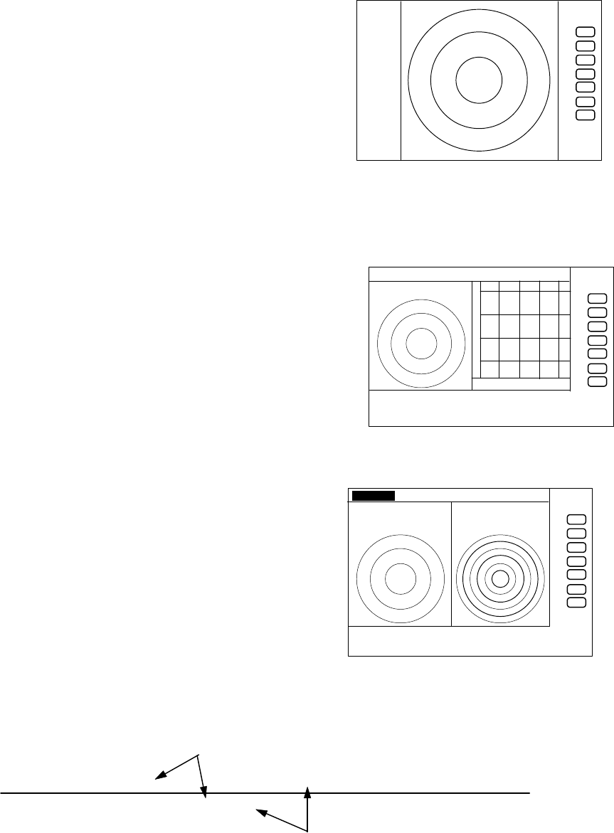
41
Press the "PICTURE " key, a normal display will appear if reverse display has been selected, and a
reverse display if normal display selected.
Note: Please refer to "5.5.4.3 Reversing the screen (PICTURE)".
5.4.23 Change to PPI screen ( PPI )
Press the "PPI" key, the screen will change to PPI
screen.
Use to change the screen from other modes to PPI.
5.4.24 Change to SEMI3D/PPI screen ( SEMI3D )
Press the "SEMI3D" key, the screen will change to
SEMI3D/PPI screen.
Use to change the screen from other modes to
SEMI3D/PPI.
Note: All controls, such as EBLs, VRMs effects both screen.
The ZOOM, OFF-C, FL EBL2, and FL VRM2 could not
be used on this mode. The "SEMI3D" screen displays
the center as ship's heading always.
5.4.25 Change to PPI/PPI screen ( PPI/PPI )
Press the "PPI/PPI" key, the screen will change to
PPI/PPI screen. Use to change the screen from other
modes to PPI/PPI.
Note:
(1) The radar picture is refreshed with two scanning
interval for each screen. Right screen picture is holded
during refreshing left screen, left screen holded during
refreshing right screen. When your ship navigates in
high speed, use PPI screen to get fast refreshing picture.
LEFT screen /―――/・・・・・・/―――/・・・・・・/―――/・・・・・・ time→
RIGHT screen ・・・・・・ /―――/・・・・・・/―――/・・・・・・/―――/
(2) The ZOOM, OFF-C, FL EBL2, and FL VRM2 could not be used on this mode.
(3) The range, GAIN, STC, FTC, GZ can be used independently for selected window with "SEL
.75
.25
HU
+
PPI screen
.75 .25 HU S
+
280 320 000 040 080
SEMI3D/PPI screen
.75
.25 HU S
24
6
+
G 55/35
S 35/AT
F 35/AT
PPI/PP I screen
refreshing radar picture
holding previous picture
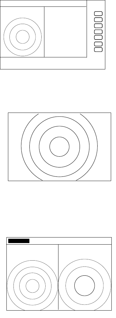
42
WIN".
Selected window is that the range displayed in reverse character. Please refer to "SEL WIN".
(4) The cross cursor can be controlled on selected window.
5.4.26 Change to PPI/NAV screen ( PPI/NAV )
Press the "PPI/NAV" key, the screen will change to
PPI/NAV screen.
Use to change the screen from other modes to
PPI/NAV.
Note:
The ZOOM, OFF-C, FL EBL2, and FL VRM2 could not
be used on this mode.
5.4.27 Change to ALL PPI screen ( ALL PPI )
Press the "ALL PPI" key, the screen will change to ALL
PPI screen.
Use to change the screen from other modes to ALL PPI.
Note:
(1) The range, rings interval, display mode are displayed on the
upper left of the screen.
(2) Return to PPI screen mode pressing a key except MENU,
range UP or DOWN, or POWER key.
5.4.28 Change to ALL PPI/PPI screen ( ALL PPI2 )
Press the "ALL PPI2" key, the screen will change to
ALL PPI/PPI screen.
Use to change the screen from other modes to ALL
PPI/PPI.
Note:
(1) The range, rings interval, display mode are displayed on
the upper left of each screen.
(2) Return to PPI/PPI screen mode pressing a key except
MENU, range UP or DOWN, or POWER key.
(3) The radar picture is refreshed with two scanning
interval for each screen. Right screen picture is holded
during refreshing left screen, left screen holded during refreshing right screen. When your
ship navigates in high speed, use PPI screen to get fast refreshing picture.
.75 .25 HU S
+
NAV DISPLAY
WAY P 123.4°
6.8NM
COURSE 2.38NM
XTE <<<
HDG 267.3°T
SPD 12.8KT
TEMP 20.8° C
DEPTH 58.3 M
LAT/LON
34°08.22N
138°02.53E
PPI/NAV screen
.75
.25
HU
+
ALL PPI screen
.75
.25 HU S
.25
.125
+
ALL PPI/PPI screen
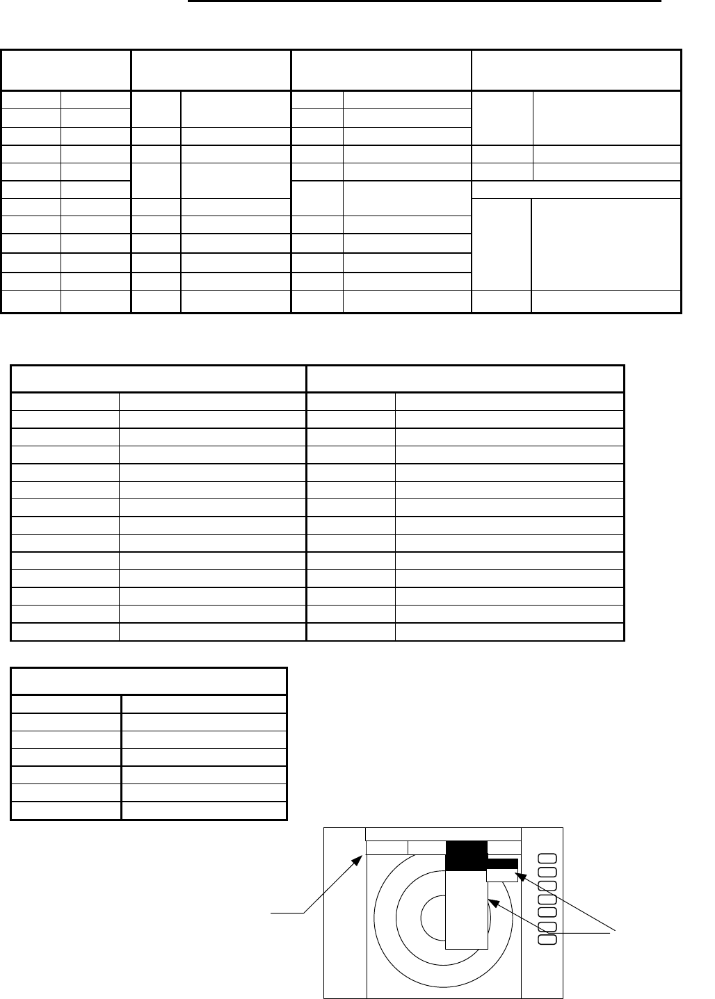
43
●
5.5 MENU Operation
・List of MENU
List of Main Menu
MARK
(MAIN-MENU)
NAV
(MAIN-MENU)
ECHO
(MAIN-MENU)
SETUP
(MAIN-MENU)
EBL1 ON/OFF GAIN AUTO/MAN
VRM1 ON/OFF
MODE HU/HS/NU/CU/TM
(MANU/NMEA)STC AUTO/MAN/HARBOR
EBL2 ON/OFF GZ ON/OFF FTC AUTO/MAN
WINDOW PPI/SEMI3D+PPI/
PPI+PPI/PPI+NAV/
ALL PPI/ALL PPI+PPI/MOB
VRM2 ON/OFF OFF-C ON/OFF TUNE AUTO/MAN SEL WIN
FL EBL2 ON/OFF ST OFF/ST1/ST2 PICTURE DAY/NIGHT
FL VRM2 ON/OFF SLEEP OFF/5min/10min/
15min SYSTEM CHECK
HDG OFF OFF TRACK OFF/15SEC/30SEC/
1MIN/3MIN/6MIN/CONT
///CSR ON/OFF ZOOM ON/OFF
RINGS ON/OFF SL SHORT/LONG
VAR RNG ON/OFF
TARGET
CUSTOM KEY ASSIGNMENT
PRESET1 (SUB-MENU)
PRESET2 (SUB-MENU)
ADJUST (SUB-MENU)
+MK LINE ON/OFF
List of Custom Menu
PRESET1 (SUB-MENU) PRESET2 (SUB-MENU)
HM FLSH ON/OFF GZ LEVEL 1∼7
STERN M ON/OFF GZ MODE IN/OUT
NORTH M ON/OFF HOLD ON/OFF
ST’BY NAVI/NOR DISPLAY RDR/MONI/NAV
BUZ VOL OFF/LOW/HIGH EXT BUZ OFF / CONT / INT
RM UNIT NM / KM / SM IN P/R 1080/1024/2048/4096/360
DEPTH M / FT / FM OUT P/R 1080/1024/2048/4096/360
TEMP °C / F DEMO ON / OFF
EBL BRG REL / TRUE / MAG IR OFF / IR1 / IR2
WP BRG TRUE / MAG SPD SET NMEA / MANU 0.0 KT
HEAD INPUT NMEA / SIN・COS /12BIT / 10BIT LANGUAGE 15 countries
HEAD TRUE / MAG
+MK MODE DIST・BRG / LAT・LON
P TABLE 0 ∼ 2
ADJUST (SUB-MENU)
TIMING ADJ
HEAD ADJ
TUNING CAL.
ANTENNA 1∼9
AUTO GAIN 1∼30
AUTO STC 1∼16
HARBOR 1∼16
+
ST‘B
.75
.25
HU
STC
FTC
TUNE
ST
TRACK
ZOOM
S/L
▼▼▼▼▼▼▼
MARK NAV ECHO SETU
P
ECH
O
GAIN
▼
▼
MAN
AUTO
MAIN-MENU
SUB-MENU
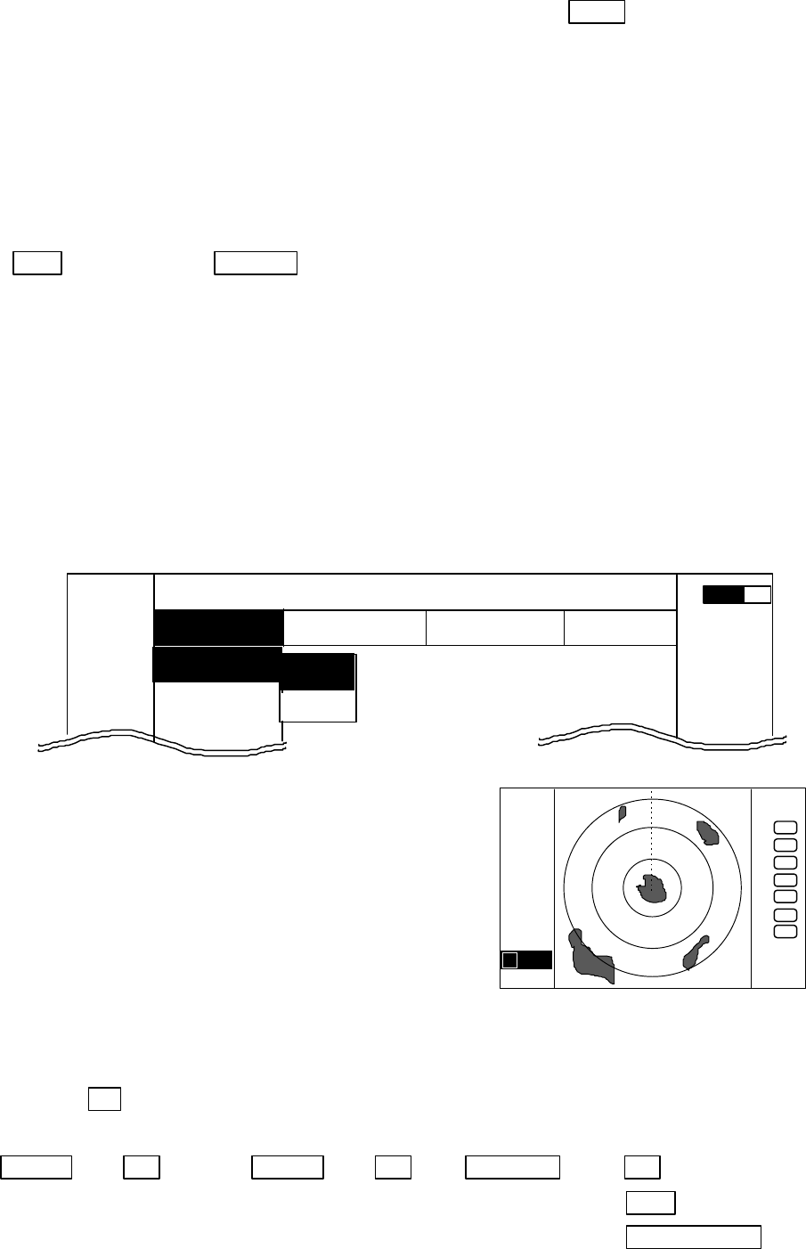
44
5.5.1 Mark Menu
××× = keys to press
Setting for markers and cursors
・
Common operations for the MARK menu
(Up to the point when "MARK" menu is selected from the main menu)
Press the "MENU" key and select "MARK" from the displayed 4 main menus using the left-right
cursor. (The contents of the selected MENU will appear on a pull-down display in accordance with the
movement of the left-right cursor.)
MENU ――> Left/Right
(Select MARK)
Further explanation about the MARK menu will be conducted on the assumption that this "common
operation for the MARK menu" has already been completed.
5.5.1.1 Bearing measurement (EBL1)
(1) Select EBL1 from the pull-down display items using the up-down cursor key, and press the "ENT"
key.
(2) When the ON/OFF sign is displayed beside the EBL1 item, select ON with the up-down cursor keys
and press the "ENT" key.
(3) When the "ENT" key is pressed, electric bearing line
(EBL1) appears and the angle from the direction of the
ship’s head which is set at 0 degree will appear in a
reverse display at the lower left of the screen.
(4) Place the marker on the center of the target with the
control knob and read the bearing. Then, the display
setting for EBL1 will be completed either (a)with the
EBL1 display still on the screen if the "ENT" key is
pressed, or (b)without the EBL1 display if the "MENU"
key is pressed. (c)Pressing another function key will
lead to the function of that key with the EBL1 display
still on the screen.
Note: 1 ×××.×°indicates EBL1.
Up/Down −> ENT −> Up/Down −> ENT −> Control knob −> ENT (a)
(Select EBL1) (Select ON) (EBL1 operation) └> MENU (b)
└> Other function key (c)
Note: The displayed EBL angle is relative to heading or true to north, depends on the setting of
"EBL BRG" in the "SETUP" menu.
MARK
EBL1
VRM1
EBL2
.75
.25
HU NAV ECHO SETUP
MARK
▼▼▼
▼
▼
▼
▼
0.23
A
.75
.25
HU
+
1 0.0°
OFF
ON
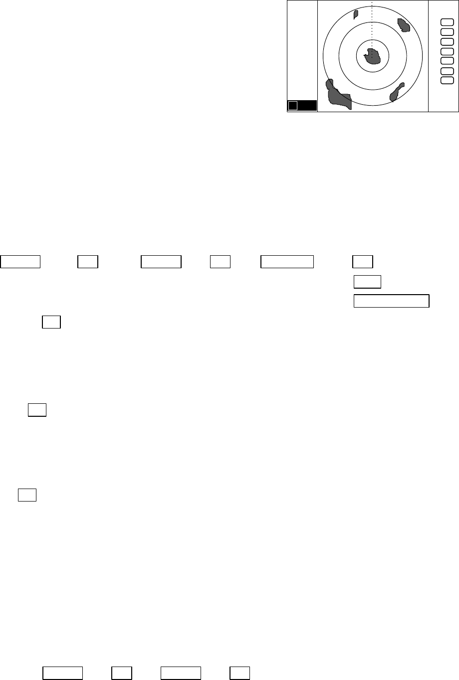
45
5.5.1.2 Determining the distance (VRM1)
(1) Select VRM1 from the pull-down display items using
the up-down cursor key, and press either the "ENT"
key.
(2) When the ON/OFF sign is displayed beside the VRM1
item, select ON with the up-down cursor keys and
press the "ENT" key.
(3) When the "ENT" key is pressed, the variable range
marker1 (VRM1) and the distance in a reverse display
appears at the lower left of the screen (See Note), and
the display is set for VRM1.
(4) Place the marker on the front edge of the target with
the control knob and read the distance. Then, the
display setting for VRM1 will be completed either
(a)with the VRM1 display still on the screen if the
"ENT" key is pressed, or (b)without the VRM1 display
if the "MENU" key is pressed. (c)Pressing another
function key will lead to the function of that key with
the VRM1 display still on the screen.
Up/Down −> ENT −> Up/Down −> ENT −> Control knob −> ENT (a)
(Select VRM1) (Select ON) (VRM1 operation) └> MENU (b)
└> Other function key (c)
Note: 1 ××.××NM indicates VRM1.
5.5.1.3 Bearing measurement (EBL2)
Refer to the section “Bearing measurement (EBL1)”.
The "EBL2" will appear in a reverse display at the lower right of the screen.
Note: 2 ×××.×°indicates EBL2.
5.5.1.4 Determining the distance (VRM2)
Refer to the section “Determining the distance (VRM1)”.
The "VRM2" will appear in a reverse display at the lower right of the screen.
Note: 2 ××.××NM indicates VRM2.
5.5.1.5 Measuring the distance or angle between two points ( FL EBL2, FL VRM2 )
Determining the distance (VRM2)
(a) Preparation for the measurement
(1) Use the up-down cursor keys to select FL VRM2 from among the pull-down display items, and
press the "ENT" key.
(2) Use the up-down cursor keys to select ON from the ON/OFF display beside the FL VRM2 items,
and press the "ENT" key. “SET START POINT” is displayed and a small cross mark appears.
(Once this is set, the "ON" state continues unless changes are made.)
Up/Down −> ENT −> Up/Down −> ENT ------------------ FL VRM2 is turned ON and
(Select FL VRM2) (Select ON) the small cross mark appears.
.75
.25
HU
+
1 0.00NM
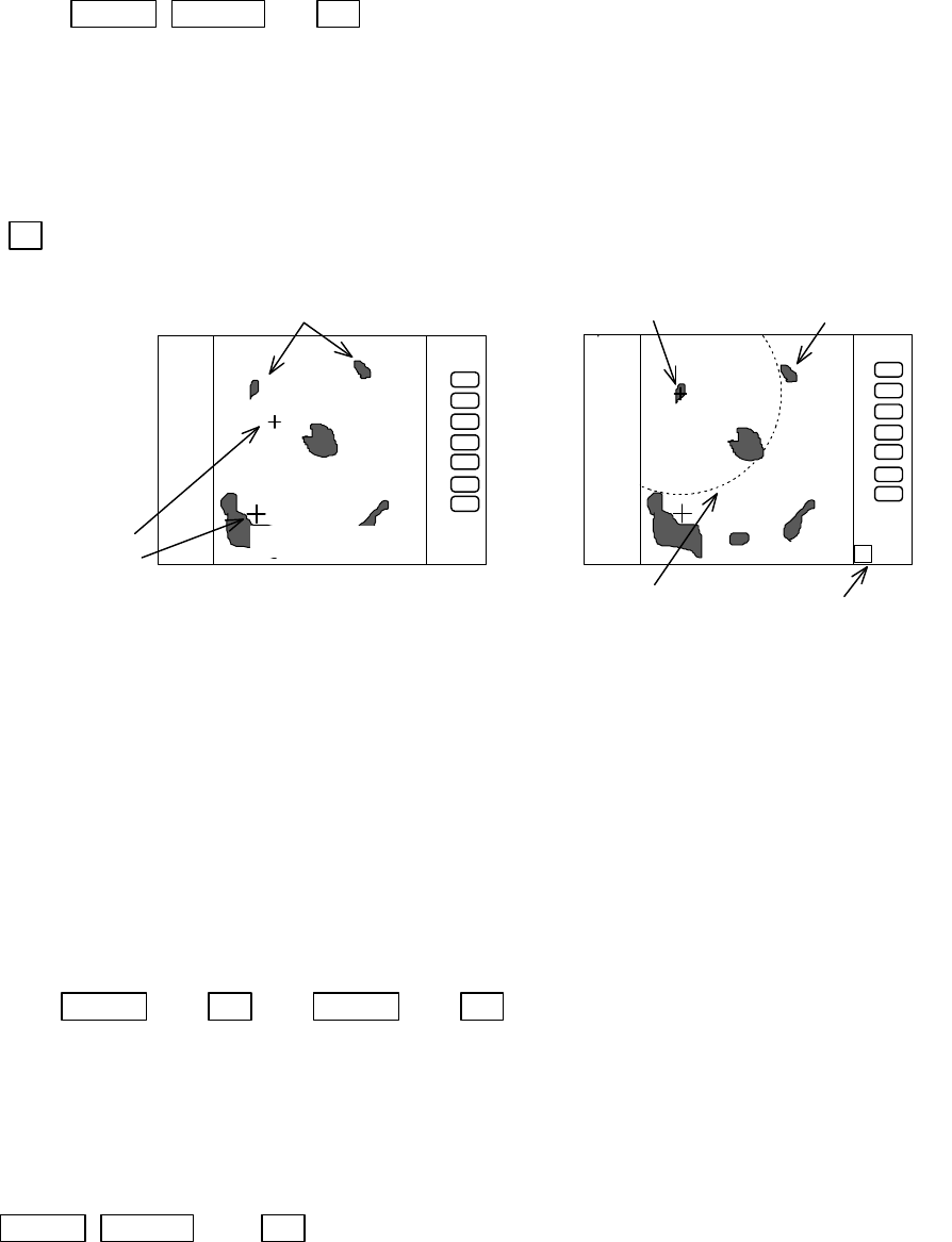
46
(b) Setting a reference point for measurement of the distance
Use the left-right and up-down cursor keys to place the small cross mark on one of the two echoes
whose distance will be measured, and press the "ENT" key.
Up/Down &Left/Right −> ENT ------------ Criterion of the reference point is set.
(Place the cross cursor on an echo)
(c) Measuring
Perform the operations in the above mentioned "Common operation for the MARK menu" and
"measuring the distance(VRM2)", and place the VRM2 on another echo.
VRM2 is displayed on the screen around the placed fixed cross cursor.
" 2 xx. xNM" which is displayed at the lower right will be the distance between the two points.
Note: EBL2 and VRM2 are not follow to "ZOOM" and "OFF-C" function.
5.5.1.6 Measuring the angle between two points (FL EBL2)
(a) Preparation for the measurement
(1) Use the up-down cursor keys to select FL EBL2 from among the pull-down display items, and
press the "ENT" key.
(2) Use the up-down cursor keys to select ON from the ON/OFF display beside the FL EBL2 items,
and press the "ENT" key. “SET START POINT” is displayed and a small cross mark appears.
(Once this is set, the "ON" state continues unless changes are made.)
Up/Down −> ENT −> Up/Down −> ENT ------------------ FL EBL2 is turned ON and
(Select FL EBL2) (Select ON) the small cross mark appears.
(b) Setting a reference point for measurement of the angle.
Use the left-right and up-down cursor keys to place the small cross mark on one of the two echoes
whose angle will be measured, and press the "ENT" key.
Up/Down &Left/Right −> ENT -- Criterion of the reference point is set.
(Place the cross cursor on an echo)
(c) Measuring
Perform the operations in the above mentioned "Common operation for the MARK menu" and
"measuring the distance(EBL2)", and place the EBL2 on another echo.
EBL2 is displayed on the screen based on the placed fixed cross cursor.
.7
5
.25
HU
2 0.72
NM
place the VRM2
on another echo
center of
VRM2
SET START POINT
.7
5
.25
HU
measure the distance
between two targets
small cross mark
cross mark
FL VRM2 indication of VRM2
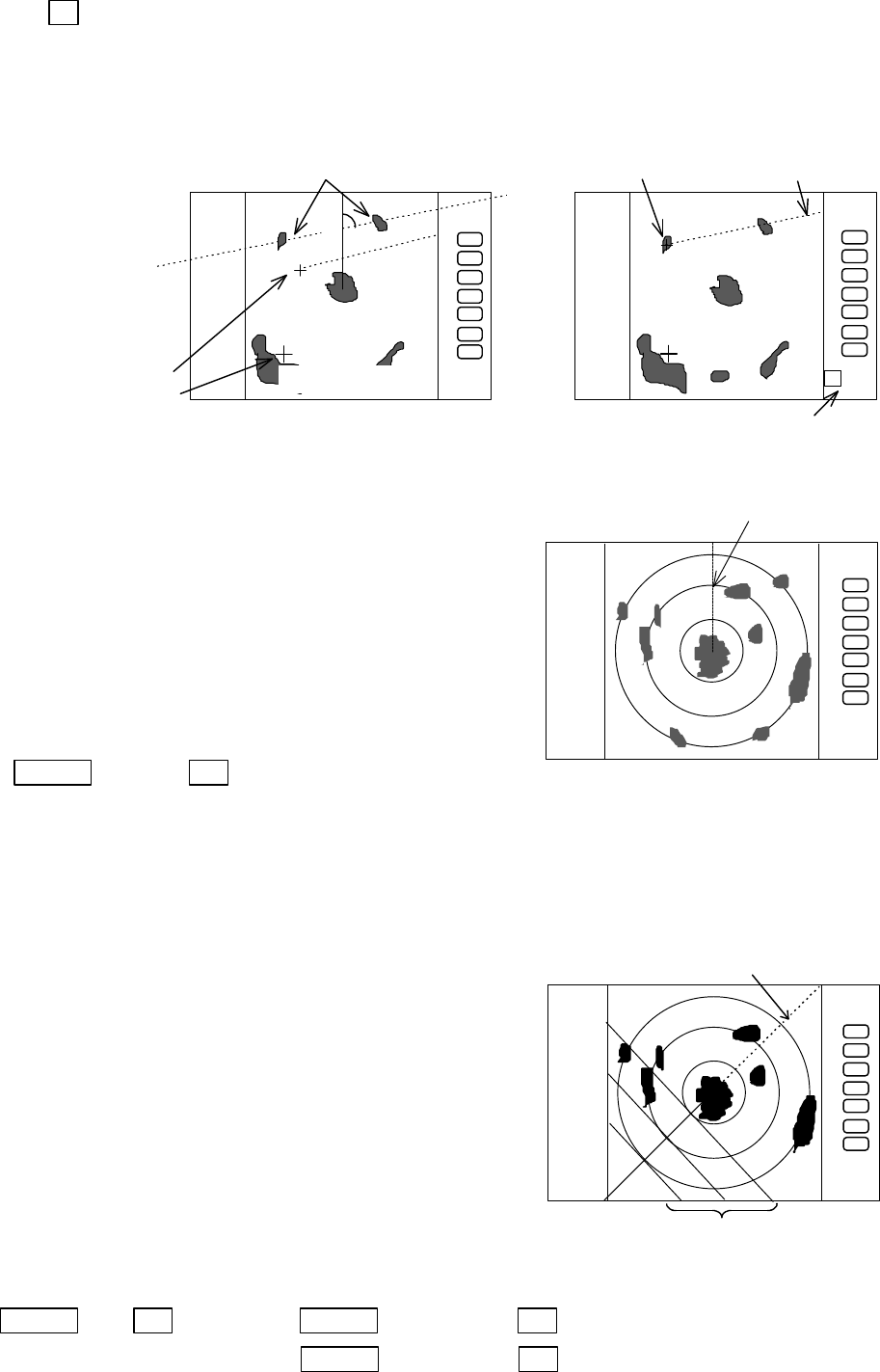
47
" 2 xx. xx°" which is displayed at the lower right will be the angle between the two points.
Note: The displayed EBL angle is relative to heading or true to north, depends on the setting of
"EBL BRG" in the "SETUP" menu.
5.5.1.7 Erasing heading maker temporarily (HDG OFF)
(1) Use the up-down cursor key to select HDG OFF from
among the pulled down and displayed items.
(2) Press the “ENT” key. The heading maker is not
displayed as long as you hold it down.
Up/Down −> ENT ---------- The heading maker is not displayed as long as you hold “ENT” key down.
(Select HDG OFF)
5.5.1.8 Using parallel cursors (///CSR)
Normally EBL is used to measure the exact bearing from the position of your ship to a target.
However, you can also use parallel cursors.
(1) Use the up-down cursor key to select ///CSR from among
the pull-down and display items, and press the “ENT”
key.(ON/OFF display beside the ///CSR item)
(2) Use the up-down cursor key to select ON .
(3) Press the “ENT” key. Parallel cursors will appear on the
screen. As you move EBL, the parallel cursors also move.
To cancel the ///CSR function, either select OFF in (2).
Up/Down −> ENT −> Up/Down (Select ON) −> ENT -----------------Parallel cursor appears
(Select ///CSR) └> Up/Down (Select OFF)−> ENT -------------Parallel cursor non-appears
Note: Interval of ///CSR same as fixed range maker.
///CSR moves with EBL1.
.7
5
.25
HU
.75
.25
HU
Not displayed while ENT key
is held down.
2 20.3°
FL EBL2
SET START POINT
.7
5
.25
HU
Origin of EBL2
measure the angle between two points
indication of
EBL2
small cross mark
cross mark
.75
.25
HU
EBL1
Parallel cursor
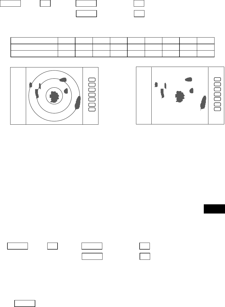
48
5.5.1.9 Establishment of the indication of the RANGE RINGS (RINGS)
(1) Use the up-down cursor key to select RINGS from among the pull-down and display items, and press
the “ENT” key.(ON/OFF displayed beside the RINGS item)
(2) Use the up-down key to select ON or OFF and press the “ENT” key
Select ON Range Rings ON
Select OFF Range rings OFF
Up/Down −> ENT −> Up/Down (Select ON) −> ENT ------------------Range rings appears
(Select RINGS) └> Up/Down (Select OFF)−> ENT -------------- Range rings non-appears
・Number of range rings and range interval
Range 0.125 0.25 0.5 0.75 1.5 3 6 12 24
Number of Rings 222366666
Interval 0.0625 0.125 0.25 0.25 0.25 0.5 1 2 4
5.5.1.10 Variable range function ( VAR RNG )
Usually the range changes in steps as 0.5--0.75--1.5--3.0--....., but using this function will enable a
consecutive change such as 0.5--0.6--0.7--0.8--..... .
(1) Use the up-down cursor keys to select VAR RNG from among the pulled down and displayed items,
and press the "ENT" key.
(2) When ON is selected with the up-down cursor key from the ON/OFF display beside the VAR RNG
item, and the "ENT" key is pressed, the VAR RNG function becomes valid and VAR will be
displayed at the upper left of the screen (beside MODE).
Setting procedure
Up/Down −> ENT −> Up/Down (Select ON) −> ENT VAR RNG function is turned ON
(Select VAR RNG) └> Up/Down (Select OFF) −> ENT VAR RNG function is turned OFF
(3) The range changes continuously with pressing the up-down cursor while the VAR RNG function is
on, and it changes in steps with the "RANGE UP" or "RANGE DOWN" keys.
Method of use
Up/Down ----------------------------- Range changes continuously
.75
.25
HU
.75
.25
HU
Range rings ON Range rings OFF
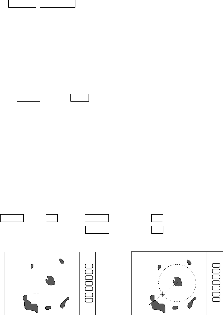
49
RANGE UP &RANGE DOWN ------------ Range changes in step
(4) To cancel the vari-range function, press a key except "RANGE UP" and "RANGE DOWN" key.
When use the function, follow from (1) again.
5.5.1.11 Output the position data of Cursor ( TARGET )
Place the cross cursor to the position that is to output position data with up-down and left-right key.
Use the up-down cursor keys to select TARGET from among the pull-down display items, and press
the "ENT" key. The L/L data of the position will be output to NMEA port with TLL format.
Up/Down −> ENT ・・・・・・・・・・・・・・・・・・・・・・・ output the L/L position of the cursor
(Select TARGET)
Note: When activate this function, nothing happened on the screen.
5.5.1.12 Follow the Distance and Bearing marker on the cursor (+MK LINE)
(1) Use the up-down cursor keys to select +MK LINE from among the pulled down and displayed items,
and press the "ENT" key.
(2) When ON is selected with the up-down cursor key from the ON/OFF display beside the +MK LINE
item, and the "ENT" key is pressed, the +MK LINE function becomes valid, and distance/bearing
marker will be displayed at the cross cursor.
Setting procedure
Up/Down −> ENT −> Up/Down (Select ON) −> ENT +MK LINE function is turned ON
(Select +MK LINE) └> Up/Down (Select OFF) −> ENT +MK LINE function is turned OFF
(3) The distance/bearing marker follows to the cross cursor until +MK LINE function is turned OFF.
.7
5
.25
HU
.7
5
.25
HU
+MK POS
230.0°
0.47
+MK POS
230.0°
0.47
+MK LINE OFF +MK LINE ON
The distance/bearing marker follows to cross
cursor. EBLs and VRMs can be used separately.
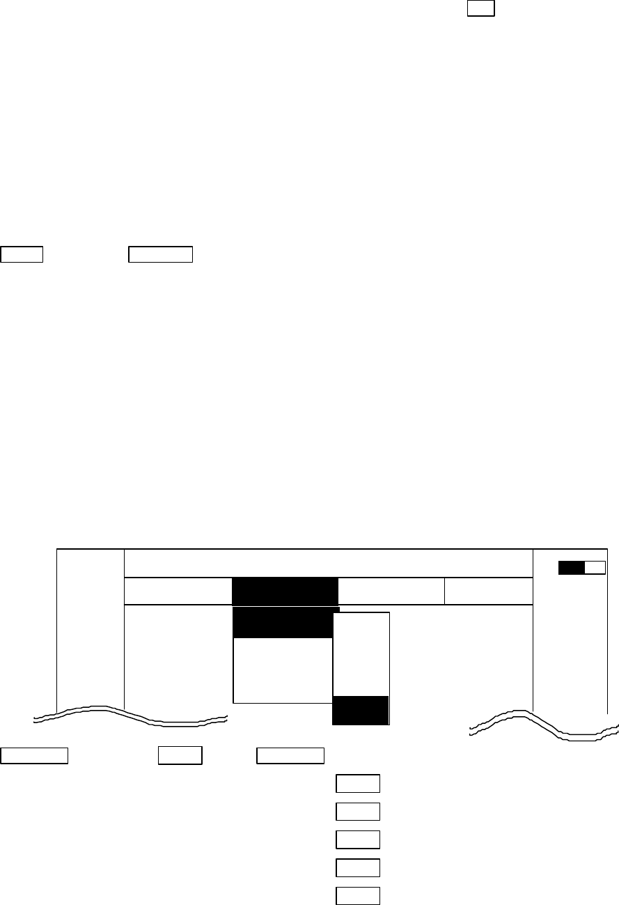
50
5.5.2 Nav (Navigation) Menu
xxx = keys to press
Radar functions for navigation aid are in this menu.
Common operations for the NAV menu
(Up to the point when "NAV" menu is selected from the main menu)
Press the "MENU" key and select "NAV" from the displayed 4 main menus using the left-right cursor.
(The contents of the selected MENU will appear on a pull-down display in accordance with the
movement of the left-right cursor.)
MENU →Left/Right
(Select NAV)
Further explanation about the NAV menu will be conducted on the assumption that this "common
operation for the NAV menu" has already been completed.
5.5.2.1 Changing display mode (MODE)
(1) Select MODE from the pull-down display items using the up-down cursor key, and press either
the "ENT" key.
(2) When the MODE sign is displayed beside the MODE item, select a mode with the up-down
cursor keys and press the "ENT" key.
(3) The display mode indicates upper-left on the screen.
UP/DOWN --> ENT --> UP/DOWN
(Select MODE)|--> (Select HU)--> ENT ・・・・・・・・・・・ HU(Head up)
|--> (Select HS)--> ENT ・・・・・・・・・・・ HS(Head set)
|--> (Select NU)--> ENT ・・・・・・・・・・・ NU(North up)
|--> (Select CU)--> ENT ・・・・・・・・・・・ CU(Course up)
--> (Select TM)--> ENT ・・・・・・・・・・・ TM(True motion)
Note1: Navigation equipment (gyrocompass, magnet compass, or GPS) must be connected to your
radar in NU, CU and TM modes.
Note2: In TM modes it is necessary to set as follow (1) or (2).
(1) Input of speed information from NMEA. (2) Set your ship’s speed manually.
Note3: TM works only on PPI screen, NU is used automatically for the other screens.
MARK
MODE >
GZ >
OFF-C >
SLEEP >
.75
.25
HU LNAV ECHO SETUP
NAVIGATION
>>>
0.23 NM
AT
HU
HS
NU
CU
TM
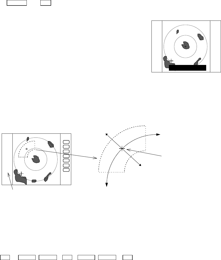
51
5.5.2.2 Guard Zone (GZ)
A function that sets a guard zone of any distance and any angle range, creating alarm tone when
either echoes above a certain level exist (IN MODE) or no echoes exist(OUT MODE).
Setting guard zone
(1) Select GZ from the pull-down display items using the up-down cursor keys, and press the “ENT”
key. ON/OFF sign is displayed beside the GZ item.
Up/Down → ENT -----------------------------------------------------------------------ON/OFF sign is displayed.
(2) Select “ON” by “common operation for the GZ menu”,
and press the “ENT” key.
(3) The present mode setting will be displayed on the left
side of the screen as GZ IN. A small cross cursor for
setting the guard zone will be displayed at the screen
center while "SET CENTER POINT" is displayed at
the bottom, activating a guard zone setting state.
(4) Use the up-down and left-right cursor keys to move the cross cursor to the center of the
warning zone to be set, and press the "ENT" key.
(5) From the cross cursor position set in (4) above as the center, expand the guard zone as
follows.
(6) After the setting the guard zone, finish by pressing the "ENT" key.
To cancel the guard zone function, select “OFF” by
“common operation for the GZ menu”, and press the
“ENT” key.
ENT → Up/Down &Left/Right →ENT → Up/Down &Left/Right → ENT ---------------------------------------------Setting completed
(Setting the center of GZ) (Setting the scope of GZ)
GZ IN
SET CENTER POINT
The central position of the guard zone.
With this point as the center, the zone
can be expanded in the directions of the
distance and the angle with the upper
and right cursor keys respectively.
Expand with the right cursor key in the
direction of the angle. Use the left
cursor key to make the zone smaller.
Expand with the up cursor key in the direction
of the distance. Use the down cursor key to
make the zone smaller.
The mode (IN or OUT) is displayed when the state is ON.
Nothing is displayed when it is OFF.
GZ IN
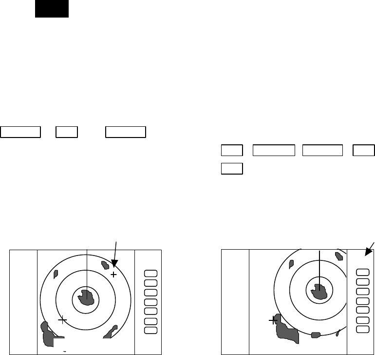
52
Stop the alarm tone
When the alarm sounds, press any key to stop. But the guard zone function is still working, the
alarm may sounds again. To "OFF" the guard zone function, select "OFF" from GZ menu.
Note1: To switch the IN or OUT mode, refer to “Guard Zone Mode” in section 5.5.4.5.3 “Changing the
content of settings 2 (PRESET2)”
Note2: To set the guard zone level, refer to “Guard Zone LeveL” in section 5.5.4.5.3 “Changing the
content of settings 2 (PRESET2)”
5.5.2.3 Shifting display in specific direction (OFF-C)
Displaying the location specified by the cross cursor as the vessel's location.
(1) Select OFF-C from the pull-down display items using up-down cursor key, and press the
"ENT" key.
(2) When the ON/OFF sign is displayed beside the OFF-C item, select ON with the up-down
cursor keys and press the "ENT" key.
(3)
OFF-C
is displayed at the upper right and "SET OFF CENTER POINT" at the bottom of the
screen, and setting is ready to be entered. Move the cross cursor with the cursor keys to
move the ship’s to the intended location, and press the "ENT" key. The ship’s location will be
displayed at the cursor's location. The display at the upper right will be normalized from the
reverse state, which indicates that the "OFF-C" state is entered.
(4) To cancel “OFF-C” function, either select OFF in (2)
Up/Down → ENT → Up/Down
(Select OFF-C) → (Select ON) ENT →Left/Right &Up/Down →ENT ----Set OFF-C
→ (Select OFF) ENT ----------------------------------------- Cancel OFF-C
Note: VRM2 and EBL2 do not follow the OFF-C function while floating.
The function operates only on PPI screen.
5.5.2.4 Setting of the SLEEP function(SLEEP)
This function sends a 30-second-transmissions during pre-fixed hours. After a transmission, a
power-saving mode is entered with the screen in ST'BY state (the scanner-OFF state) and the LCD
backlight turned off. This action is repeatedly executed.
Usage example, set a guard zone and have the warning signal automatically confirmed every
prefixed period.
.75
.25
HU
.75
.25
HU
SET OFF-C POINT
OFF-C
Move the cross cursor indicates "OFF-C" state is entered
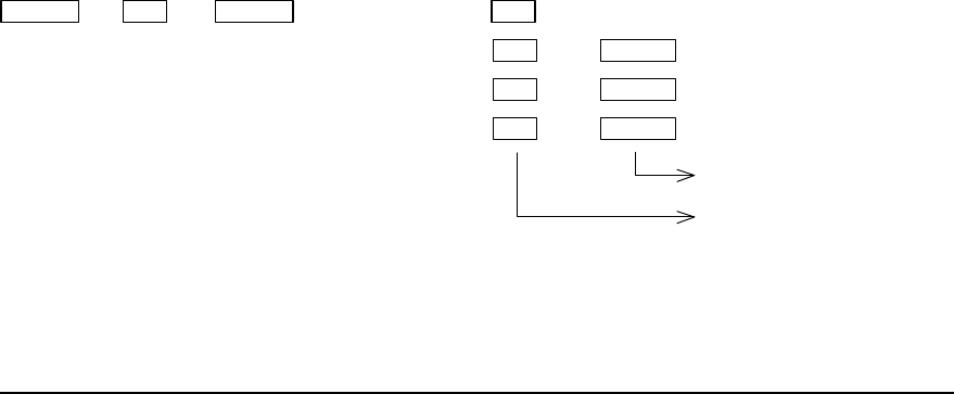
53
(1) Use the up-down cursor keys to select SLEEP from among the pull-down display items, and
press the "ENT" key.
(2) When the OFF/5min/10min/15min display has appeared beside the SLEEP item, select a time to
be set with the up-down cursor keys.
(3) Press the "ENT" key and the setting is completed. When the SLEEP function is to be canceled,
select OFF in (2).
When a transmission is conducted after setting a SLEEP mode, a ST'BY state is entered and the
backlight turns off after a 30-second-transmission. (Power-saving mode). Two minutes before the
fixed time the backlight turns on and the 2-minute timer starts. Then, at the fixed time another
30-second-transmission begins. This series of actions are repeated. If any one key is pressed
during the course of this action, the SLEEP function will be canceled.
(a) Setting procedure
Up/Down → ENT → Up/Down → (Select OFF) → ENT ----------------------------- SLEEP function is turned OFF
(Select SLEEP) → (Select 5min.) → ENT → POWER --------30-second-transmission every 5 min.
→ (Select 10min.) → ENT → POWER ------30-second-transmission every 10 min.
→ (Select 15min.) → ENT → POWER ----- 30-second-transmission every 15 min.
Transmission
Setting completed
(b) Action after setting
SLEEP setting(5min.) (Operation)
⇓
⇑(Under Tx) ⇑(Under power-saving mode)⇑(2min. timer in use)⇑ (Under Tx)⇑ (Under power-saving mode)
0 sec. 30 sec. 3 min. 5min. 5and a half min. (Time used)
TX Start TX OFF Backlight ON Tx Start TxOFF (Action)
Countdown start
-- What happens if a key is pressed after a SLEEP mode setting?
If a transmission is conducted and a key is pressed after setting a SLEEP mode, power-saving
mode is entered 30 seconds after key is pressed.
-- What happens if a key is pressed during the SLEEP mode?
a) If a key is pressed during the power-saving mode, the SLEEP function is canceled and the 2-
minute timer starts.
b) If a key is pressed while the 2-minute timer is in use, or during transmission , the SLEEP function
is canceled.
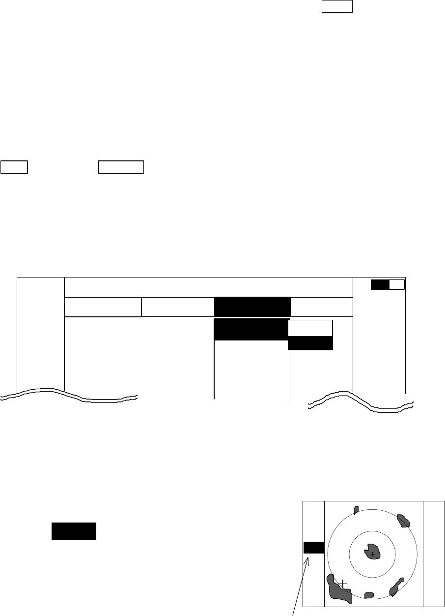
54
5.5.3 Echo Menu
××× = keys to press
Adjustment options to be conducted on the echoes displayed on the screen
・
Common operations for the ECHO menu
(Up to the point when "ECHO" menu is selected
from the main menu)
Press the "MENU" key and select "ECHO" from the displayed 4 main menus using the left-right
cursor. (The contents of the selected MENU will appear on a pull-down display in accordance with
the movement of the left-right cursor.)
MENU ――> Left/Right
(Select ECHO)
When the above-mentioned operations have been conducted, the items of the ECHO menu are
vertically displayed.
Further explanation about the ECHO menu will be conducted on the assumption that this
"common operation for the ECHO menu" has already been completed.
5.5.3.1 Sensibility adjustment (GAIN)
(1) Use the up-down cursor keys to select GAIN from among the pull-down display items, and
press either the "ENT" key or the right cursor key.
(2) Select MANU from the MANU/AUTO display beside the GAIN item using the up-down cursor
keys, and press the "ENT" key.
(3) The present state of GAIN is displayed in reverse on the
screen left as
G 35
and an adjustable state is entered.
When the control knob are operated in this state, the figure
alternates within a range of 0 and 99 and the GAIN can thus
be adjusted.
(4) The adjustment is completed by pressing the "ENT" key
after adjustment.
When AUTO action is to be entered, select AUTO in (2)
and press the "ENT" key to complete the setting.
G 5
6
The setting value is displayed during
MANUAL operation.
AT is displayed during AUTO operation.
(The same applies to STC, FTC and TUNE.)
MARK
.75
.25
HU LNAV ECHO SETUP
ECHO
▼
▼
▼
▼
0.23
NM
GAIN
STC
FTC
TUNE
ST
▼
▼▼▼▼
MAN
AUT
AT
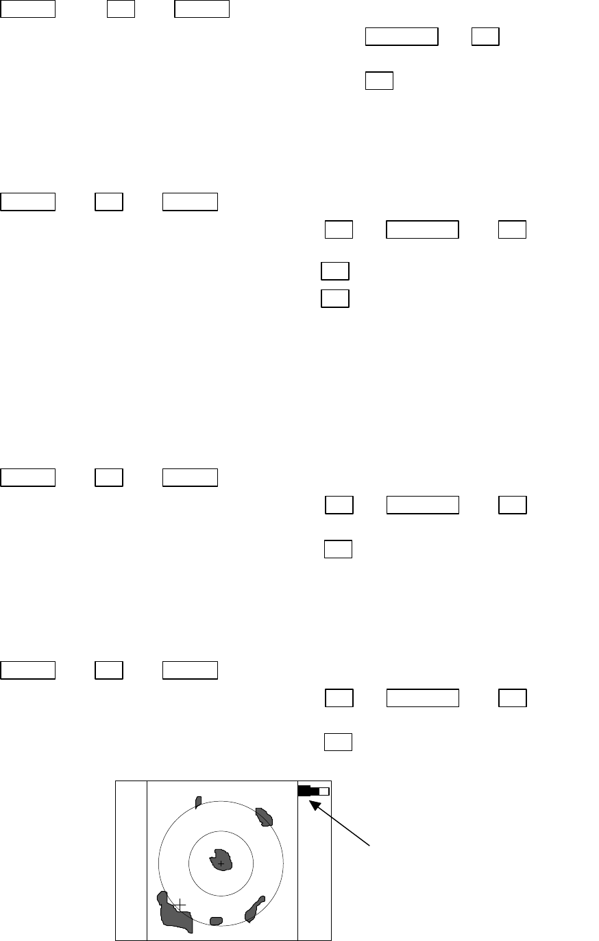
55
Up/Down −> ENT −> Up/Down
(Select GAIN) └>(Select MANU) −> Control knob −> ENT --- Set to MANU mode
|(GAIN adjustment)
└>(Select AUTO) −> ENT ---------------------Set to AUTO mode
5.5.3.2 Removing sea clutter (STC)
Refer to the section, “Sensibility adjustment (GAIN)”.
Up/Down −> ENT −> Up/Down
(Select STC) └>(Select MANU) −> ENT −> Control knob −> ENT Set to MANU mode
|(STC adjustment)
└>(Select AUTO) −> ENT ----------------------------Set to AUTO mode
└>(Select HARBOR)−> ENT --------------------------------------------
Set to HARBOR mode
Note: When you select MANU mode, GAIN and FTC will be switched to MANU mode, too.
Note: When you select HARBOR mode, FTC will be switched to MANU mode.
5.5.3.3 Removing rain and snow clutter (FTC)
Refer to the section, “Sensibility adjustment (GAIN)”.
Up/Down −> ENT −> Up/Down
(Select FTC) └>(Select MANU) −> ENT −> Control knob −> ENT Set to MANU mode
|(FTC adjustment)
└>(Select AUTO) −> ENT ----------------------------Set to AUTO mode
5.5.3.4 Adjusting receiver tuning (TUNE)
Refer to the section, “Sensibility adjustment (GAIN)”.
Up/Down −> ENT −> Up/Down
(Select TUNE) └>(Select MANU) −> ENT −> Control knob −> ENT Set to MANU mode
|(TUNE adjustment)
└>(Select AUTO) −> ENT ----------------------------Set to AUTO mode
35
Indicated setting value on manual mode,
AT on auto mode
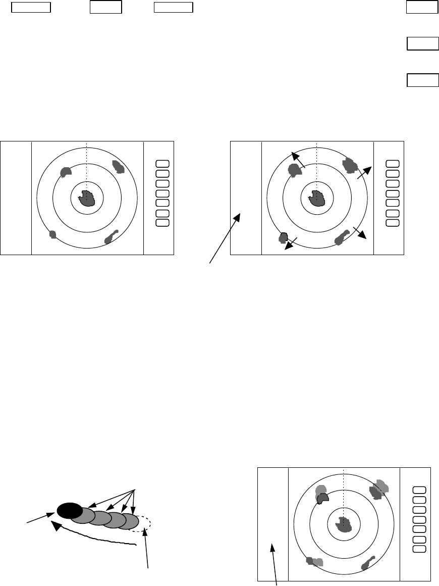
56
5.5.3.5 Echo expansion (ST)
Expanding the echo to the direction of the distance.
Two types of echo expansion exist, select ST1 or ST2 from the menu.
(1) Use the up-down cursor keys to select ST from among the pull-down display items, and press
the "ENT" key.
(2) Select ST1 or ST2 from the display beside the ST item using the up-down cursor keys, and
press the "ENT" key.
Up/Down −> ENT −> Up/Down −> (select ST1)・・・・・・・・・・・・・・・・・・・・ −> ENT
set ST1
└> (select ST2)・・・・・・・・・・・・・・・・・・・・・−> ENT
set ST2
└> (select OFF)・・・・・・・・・・・・・・・・・・・・・−> ENT
ST OFF
( expansion rate ST1<ST2 )
5.5.3.6 Displaying locus of target (TRACK)
(1) Use the up-down cursor keys to select TRACK from among the pull-down display items, and
press the "ENT" key.
(2) Select 15SEC, 30SEC, 1MIN, 3MIN, 6MIN, or CONT from the display beside the TRACK item
using the up-down cursor keys, and press the "ENT" key.
"TRK 15S" is displayed on the left side of the screen and track mode is entered. 15S indicates
the length of the track, and displays a maximum of 15-second-long sailing track.
Note: When PPI+PPI or ALL PPI+PPI screen mode is used, TRACK function can be used only on CONT mode.
.75
.25
HU
+
ST1
.75
.25
HU
+
The picture to display echoes
expanded in the direction of
the distance
ST1, or ST2 display,
no display on OFF state
ST function is OFF
disappear after selecting time
real echo
locus of target
moving direction
the length of the track
.75
.25
HU
+
TK 15SEC

57
up/down −> ENT −> up/down −> (select OFF)・・・・・・・・・・・・・ −> ENT
TRACK OFF
└> (select 15SEC)・・・・・・・・・・・・・・・・・・・・・・・・・・・・・・・・・・−> ENT
set 15sec. track
└> (select 30SEC)・・・・・・・・・・・・・・・・・・・・・・・・・・・・・・・・・・−> ENT
set 30sec. track
└> (select 1MIN)−> ENT ・・・・・・・・・・・・・・・・・・・・ set 1 min. track
└> (select 3MIN)−> ENT ・・・・・・・・・・・・・・・・・・・・ set 3 min. track
└> (select 6MIN)−> ENT ・・・・・・・・・・・・・・・・・・・・ set 6 min. track
└> (select CONT)・・・・・・・・・・・・・・・・・・・・・・・・・・・・・・・・・・・−> ENT
set continue track
5.5.3.7 Enlarging selected areas (ZOOM)
The video image centering around the cross cursor is doubled as it is displayed on the screen.
(1) Use the up-down cursor keys to select ZOOM from among the pull-down display items, and press
the "ENT" key.
(2) Select ON the using up-down cursor keys from the ON/OFF display beside the ZOOM item, and
press the "ENT" key.
(3) A small cross cursor for setting and "SET ZOOM POINT" are displayed at the screen center and
at the bottom respectively, and the magnification point is to be set. Use cursor keys to move the
cross cursor to the point to be magnified, press the "ENT" key and the setting is completed. The
area around the cross cursor is displayed in 2x magnification, with blinking "ZOOM" displayed at
the screen upper right, indicating that a ZOOM display is being conducted.
To cancel the ZOOM function, either select OFF in (1) or begin operation of range.
Up/Down −> ENT −> Up/Down (Select ON) −> ENT −> Up/Down &Left/Right −> ENT ZOOM Setting
(Select ZOOM) |(Move cross cursor)
└> (Select OFF) −> ENT ----------------------------- ZOOM canceled
Note 1) VRM2 and EBL2 do not follow the ZOOM function during a floating state.
Note 2) Normal screen returns when you change the range scale.
Note 3) ZOOM function is usable only in PPI screen.
Note 4) ZOOM function is unusable in OFF-C.
Note 5) Center of ZOOM can be set any desired position within the set range.
blinking "ZOOM"
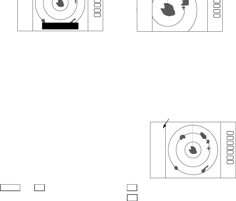
58
5.5.3.8 Increasing sensitivity (S/L)
The pulse width is automatically changed as you change the range. However, if you want to
increase sensitivity, you can choose sensitivity from two pulse widths. The short pulse (SHORT) gives
you sharp images with high distance resolution. The long pulse (LONG) provides high sensitivity and
shows targets in large size for easy identification although distance resolution is reduced.
(1) Use the up-down cursor keys to select S/L from among the pull-down display items, and press
the "ENT" key.
(2) Select Pulse length(SHORT or LONG) using the up-
down cursor keys from the SHORT/LONG display beside
the S/L item
(3) The setting will be completed when the “ENT” key is
pressed after the selection.
Up/Down −> ENT −>(Select SHORT) −> ENT ----------------------Set to short pulse
└>(Select LONG) −> ENT ------------------------Set to long pulse
SET ZOOM POINT
.75
.25
HU
S
+
indicated S or L
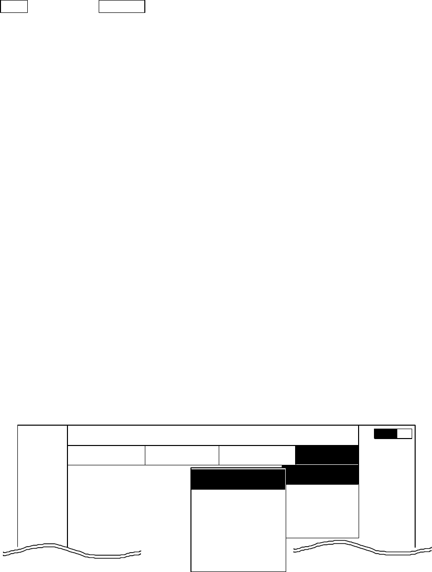
59
5.5.4 SETUP Menu
To be used for various settings and switching of the screen
・
Common operations for the SETUP menu
(Up to the point when "SETUP" menu is selected
from the main menu)
Press the "MENU" key and select "SETUP" from the displayed 4 main menus using the left-
right cursor. (The contents of the selected MENU will appear on a pull-down display in accordance
with the movement of the left-right cursor.)
MENU ――> Left/Right
(Select SETUP)
When the above-mentioned operations have been conducted, the items of the SETUP menu are
vertically displayed. Further explanation about the SETUP menu will be conducted on the
assumption that this "common operation for the SETUP menu" has already been completed.
5.5.4.1 Initiating the screen display (WINDOW)
A function to switch the display method of the screen. A selection can be made from among
the 7 patterns of screen arrangements, from the ordinary PPI display to the 2-screen PPI display,
etc.
a) PPI screen
b) PPI screen & SEMI3D screen
c) PPI screen & PPI screen (Range can be operate in each screen.)
d) PPI screen & Navigation screen
e) All PPI screen (PPI, all the screen display.)
f) All PPI screen & All PPI screen(PPI & PPI, all the screen display.)
g) MOB screen
(1) Use the up-down cursor keys to select WINDOW from among the pull-down display items, and
press the "ENT" key.
(2) Select a screen to be displayed with the up-down cursor keys from among the above 7 items
that are displayed beside the WINDOW item.
(3) The setting will be completed when the "ENT" key is pressed after the selection.
MARK
WINDOW
SEL WIN
PICTURE
SYSTEM CHECK
CUSTOM
.75
.25
HU NAV ECHO SETUP
SEMI3D/PPI
PPI/PPI
PPI/NAV
ALL PPI
ALL PPI/P
PI
PPI
SETUP
▼▼▼
▼
▼
▼
▼
0.23
NM
A
▼
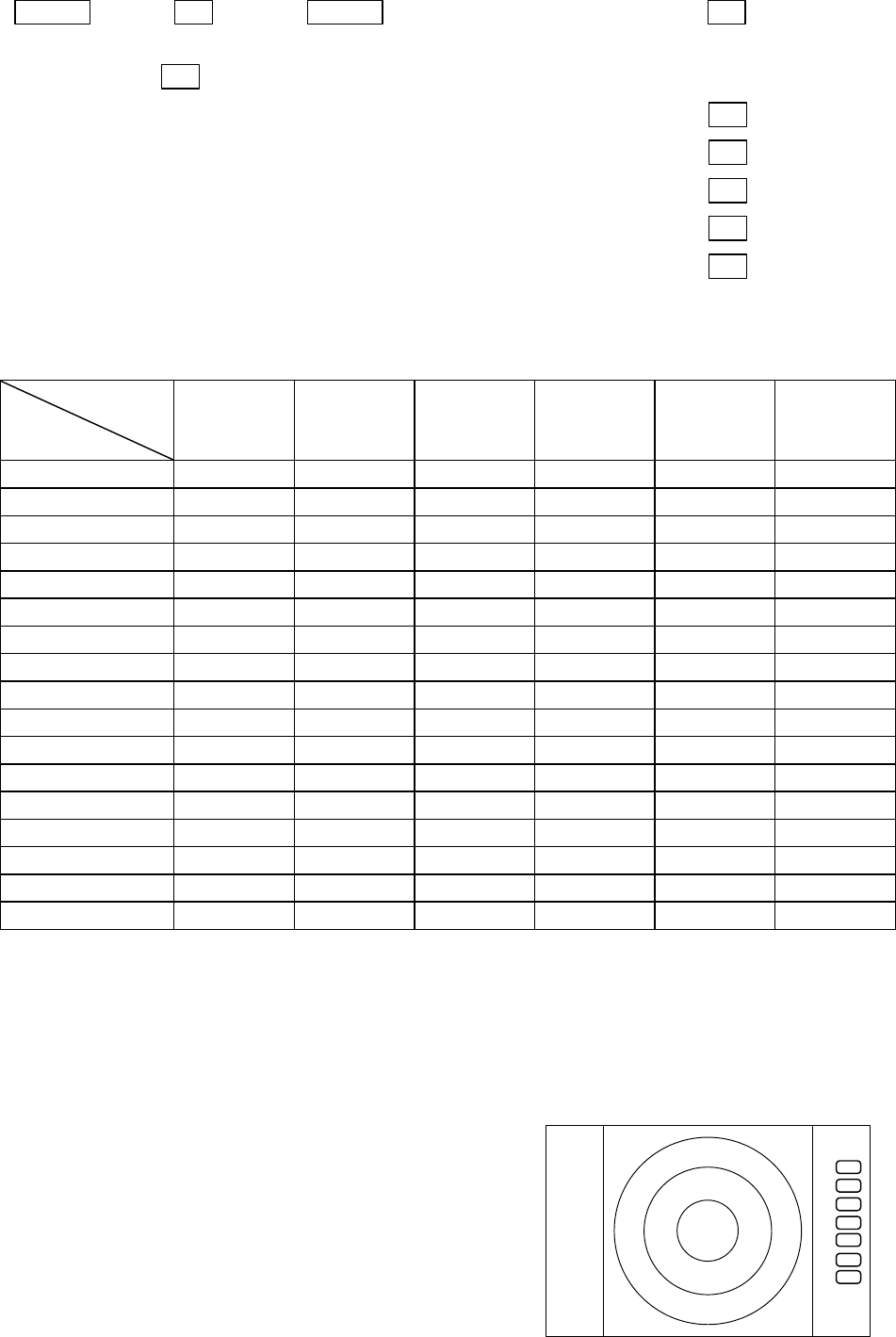
60
Up/Down ―> ENT ―> Up/Down ――> (Select PPI) −> ENT (a)
(select WINDOW) └−> (Select PPI+SEMI3D)
−> ENT (b)
└−> (Select PPI+PPI) −> ENT (c)
└−> (Select PPI+NAV) −> ENT (d)
└−> (Select ALL PPI) −> ENT (e)
└−> (Select ALL PPI+PPI) −> ENT (f)
└−> (Select MOB) −> ENT (g)
-The limitation of the operation when it was set on each screen.
S
CREEN
ITEM
PPI PPI/SEMI3D
PPI/NAV PPI+PPI ALL PPI ALL PPI PPI MOB
RANGE 〇○◎○◎×
VRM1、EBL1 ○○△×××
VRM2、EBL2 〇○△×××
FL VRM2・EBL2 〇×××××
RINGS ON/OFF 〇○○○○×
ZOOM、OFF CENT 〇×××××
///CSR 〇○△○○×
HDG OFF 〇○○×○×
STERN M ○○○○○×
NORTH M 〇○○○○×
GAIN、STC、FTC 〇○◎×××
TUNE ○○○×××
ST 〇○○×××
GZ ○○◎×××
SEL WIN ××○×○×
CONTRAST ○ ○ ○ ○ ○ ×
TXON/OFF ○○○○○×
◎ : Independent control at time as two screen.(Switching the screen is necessary (SEL WIN))
○ : It becomes simultaneous control at the time as two screen.
△ : It can be used only at the time of PPI screen.
× : It can’t be used.
- Screen modes and Operations
(a) PPI Screen
All functions can be used on this screen.
.75
.25
HU
+
PPI Screen
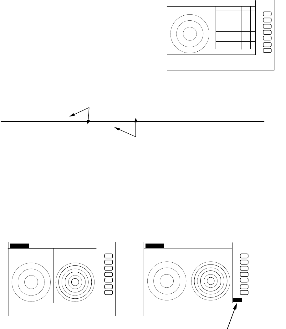
61
(b) PPI/SEMI3D Screen
It becomes simultaneous control at the time as
two screen.
Note1: All controls, such as EBLs, VRMs effects both
screen.
The ZOOM, OFF-C, FL EBL2, and FL VRM2 could
not be used on this mode. The "SEMI3D" screen
displays the center as ship's heading always.
(c) PPI/PPI Screen
The radar picture is refreshed two antenna
scanning for each PPI screen. Un-refreshed screen picture is holded during the time.
Note: The radar picture is refreshed with two scanning interval for each screen. Right
screen picture is holded during refreshing left screen, left screen holded during
refreshing right screen. When your ship navigates in high speed, use PPI screen to get
fast refreshing picture.
Note: Functions ZOOM, OFF-C, FL-EBL2, and FL-VRM2 can not be used on this screen.
Note: The function RANGE, GAIN, STC, FTC, and GZ can be used for each screen
independantly. The screen selected in "
SEL WIN
" that the range indicator displayed in
reverse can be controlled.
Note: The cross cursor displayed only on selected screen.
-Operation
a) Changing RANGE of LEFT screen
1) When the RIGHT range indicator displayed in reverse, change to LEFT screen with
"SEL WIN" function.
2) Press ”RANGE UP” or ”RANGE DOWN” key to change the LEFT screen RANGE.
b) Adjusting GAIN of LEFT screen.
1) When the RIGHT range indicator displayed in reverse, change to LEFT screen with
"SEL WIN" function.
2) Press the "GAIN" key, "
G50
" will displayed in reverse and ready for adjusting GAIN.
3) Adjust GAIN with the control knob.
Adjust STC and FTC in a same manner as GAIN.
.75 .25 HU S
+
280 320 000 040 080
PPI/SEMI3D Screen
LEFT screen /―――/・・・・・・/―――/・・・・・・/―――/・・・・・・ t→
RIGHT screen ・・・・・・ /―――/・・・・・・/―――/・・・・・・/―――/
picture drawing(refreshed)
displayed previous picture ( hold)
.75
.25
HU S
24
6
+
G 55/35
S 35/AT
F 35/AT
LEFT screen selected
.75
.25
HU S
24
6
+
G 55/35
S 35/AT
F 35/AT
GAIN adjustment for LEFT screen
Left GAIN indicates in reverse
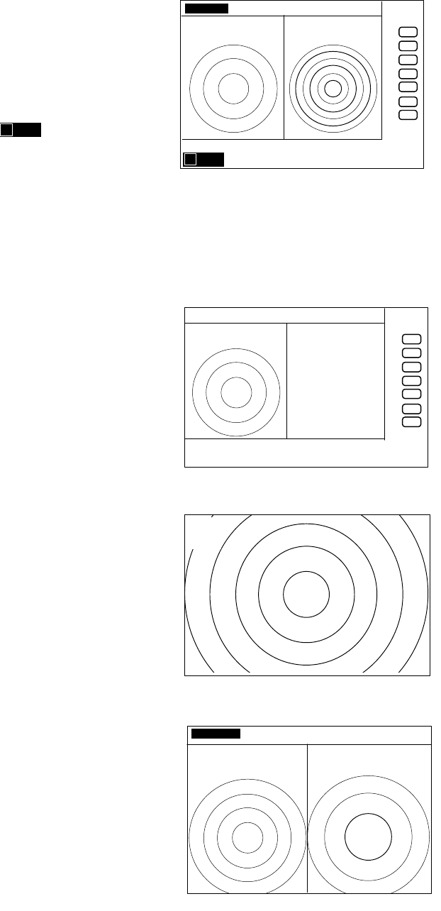
62
Note: During adjustment of GAIN, STC, or FTC, radar picture refreshing is fixed to the
adjusting screen. Approximately 5 seconds errapsed after adjustment, radar picture
refreshing is return to normal.
c) Determining the distance with VRM1 on LEFT screen.
1) When the RIGHT range indicator displayed in
reverse, change to LEFT screen with "SEL WIN"
function.
2) Press the "VRM1" key, " " will displayed
in reverse and ready for adjusting VRM1.
3) Determining the distance with the control knob.
Note: If operate the VRM1 on the RIGHT screen, VRM1
will move to the RIGHT screen.
Operate VRM2, EBL1, or EBL2 in a same manner as VRM1.
(d) PPI/NAV Screen
Note: The ZOOM, OFF-C, FL EBL2, and FL
VRM2 can not be used on this screen.
(e) ALL PPI Screen
Note1: The RANGE, RINGS interval, and Display mode
are displayed on the upper-left of the screen.
Note2: When press the key except "MENU", "RANGE
UP/DOWN", "BRILL", and "POWER", return to
PPI screen.
(f) ALL PPI/PPI Screen
Note1: The RANGE, RINGS interval, and Display mode
are displayed on the top of the screen.
Note2: When press the key except "MENU", "RANGE
UP/DOWN", "BRILL", and "POWER", return to
PPI/PPI screen.
Note3: The radar picture is refreshed with two
scanning interval for each screen. Right screen picture
is holded during refreshing left screen, left screen
holded during refreshing right screen. When your ship
navigates in high speed, use PPI screen to get fast
refreshing picture.
G 55/35
S 35/AT
F 35/AT
1 0.00NM
Determining the distance with VRM1
on LEFT screen
.75
.25
HU S
24
6
+
.75 .25 HU S
+
NAV DISPLAY
WAY P 123.4°
6.8NM
COURSE 2.38NM
XTE <<<
HDG 267.3°T
SPD 12.8KT
TEMP 20.8° C
DEPTH 58.3 M
LAT/LON
34°08.22N
138°02.53E
PPI/NAV screen
+
.75
.25
HU S
ALL PPI screen
.75
.25
HU S
.25
.125
+
ALL PPI PPI screen
1 0.00NM
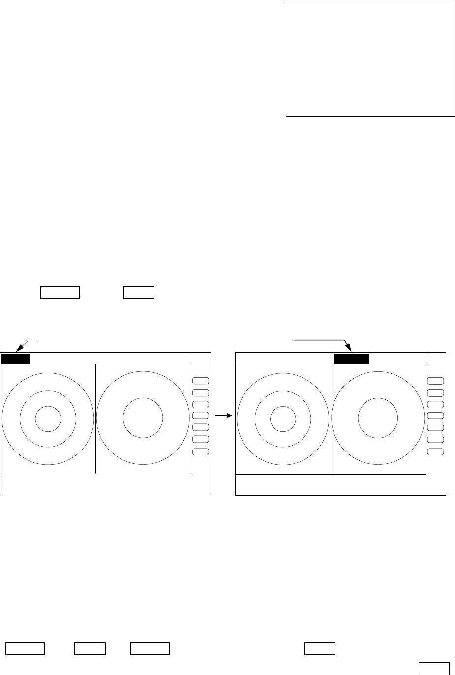
63
(g) MOB Screen
The MOB key has been pressed, the MOB position and
ship's position are displayed. If not, MOB position will be
displayed with bars( --.- )
Press MOB key to clear the MOB position and return
to previous screen. Press ENT key to return previous
screen with keeping the MOB position data.
5.5.4.2 Switching screens on PPI/PPI screen ( SEL WIN )
Switching to the desired screen for activation on a PPI/PPI screen display.
The "SEL WIN" function is switches the activated screen to effect the operation such as,
RANGE, GAIN, STC, FTC, VRM1/2, EBL1/2, and guard zone. The range indicator of activated
screen is displayed in reverse.
When "SEL WIN" is selected with the up-down cursor keys from among the pull- down display
items and the "ENT" key is pressed, activated screen will be changed to the opposite screen.
Up/Down ―> ENT ・・・・・・・・・・・・・・・・・・・・・・・・・・・・・・the opposite screen activated
(select SEL WIN)
5.5.4.3 Reversing the screen (PICTURE)
Reversing to the screen for easy viewing on weather, temperature, and day / night
environment conditions.
When "PICTURE" is selected with the up-down cursor keys from among the pull- down display
items, select "DAY" and the "ENT" key is pressed, a normal display will appear. A reverse display
will appear if "NIGHT" selected
Up/Down ―> ENT ―> Up/Down ――> (select DAY) −> ENT −> normal display
(select PICTURE) └−> (select NIGHT) ---------------−> ENT
−> reverse display
MAN OVERBOARD
MOB POS 35°08.42N
139°03.33E
SHIP
’
S POS
37°12.42N
142°04.33E
PRESS MOB KEY TO DATA CLEAR
PRESS ENTER KEY TO RETURN
Range display on the active screen become a reverse
.75
.25 S.5 .25 .75 .25 HU S
.5
.25
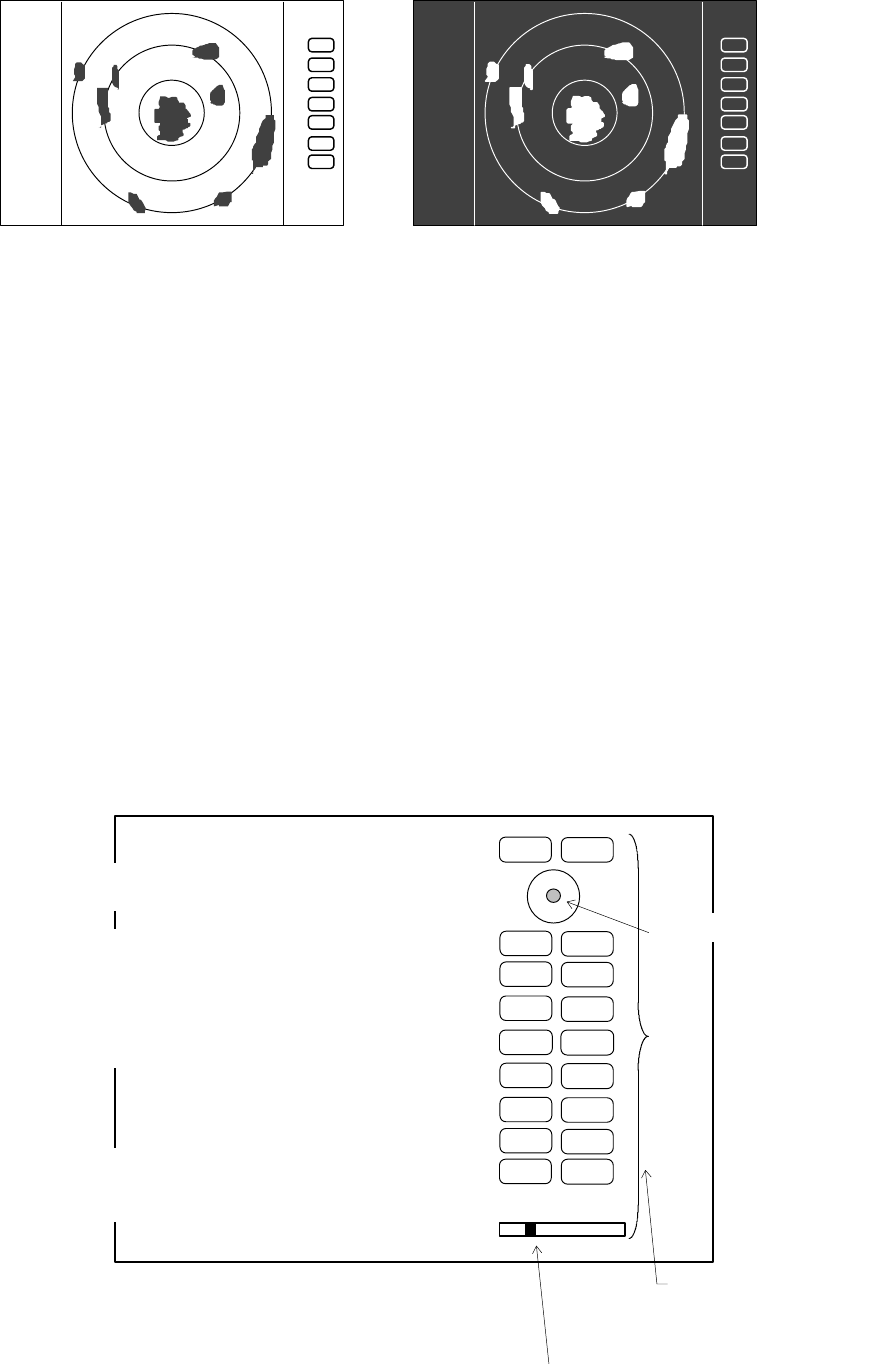
64
5.5.4.4 Fault Diagnosis by Self Check
(
SYSTEM CHECK)
Verifying the problem point by SYSTEM CHECK when, for example, some abnormality has
occurred.
(1) Select SYSTEM CHECK from the pull-down display items using up-down cursor key, and
press the “ENT” key.
(2) The system check screen will appear.
While watching the screen , check the following:
i) Whether all items are marked “OK”. (If any item is marked “NG”, the indicated location
may be faulty.)
ii) Press a front-panel key and see if the corresponding display on the screen is highlighted.
iii) Turn the control knob and see if the lower-right indicator move to right or left.
(3) Press the POWER key to return to the previous screen
a) ROM
------------------------- Indicates the ROM status.
RNG U
RNG D
BRILL
AUTO
GAIN
STC
FTC
1
2
3
4
5
6
7
MOBPOWER
n) Indicates the operation
status of front-panel keys.
SYSTEM CHECK screen
ENT
MENU
Indicates the control knob status.
Indicates the cursor status.
CONTROL KNOB
SYSTEM CHECK
MEMORY CHECK
a) ROM-------------------------- > ROM OK
b) RAM-------------------------- > RAM OK
c) Backup memory --------------- > BACKUP OK
SIGNAL CHECK
d) Transmit trigger --------------- > (1) TRIGGER OK
e) Bearing pulse------------------ > (2) AZIMUTH OK
f) Heading pulse------------------ > (3) HM OK
g) +5Vvoltage(at video circuit)--- > (4) +5V OK 5.2V
h) High voltage(at scanner)------ > (5) H.T. AT SU OK 253.2V
i) High voltage(at display)-------- > (6) H.T. AT DU OK 253.2V
j) Magnetron current ------------- > (7) MAG. CUR. OK 2.1
k) Tuning voltage----------------- > (8) TUNE OK
l) Cumulative usage time ------- > HOURMETER
Operation time ------------- > OPERATE 12.0H
Transmit time --------------- > TRANSMIT 10.3H
m) ROM version--------------- > ROM VERSION V1.00
PRESS POWER KEY TO RETURN
DAY display NIGHT display
.75
.25
HU
.75
.25
HU
65
b) RAM
----------------------
Indicates the RAM status.
c)
Backup memory---------
Indicates the backup memory status.
d)
Transmit trigger--------
Indicates the signal line status for the trigger signal sent from the scanner unit.
e
)
Bearing pulse-------------
Indicates the signal line status for the bearing signal sent fron the scanner unit.
f
)
Heading pulse ------------
Indicates the signal line status for the bow signal sent from the scanner unit.
g
)
+5V voltage ---------------
Indicates the reference voltage status of the video circuit and its voltage value.
(at video circuit)
(normally about 5 V)
h
)
High voltage(at SU) ----
Indicates the status of th high voltage supplied from the display unit to the
scanner unit and its voltag value (normally about 250 V) at scanner unit.
i
)
High voltage(at DU)-----
Indicates the status of th high voltage supplied from the display unit to the
scanner unit and its voltag value (normally about 250 V) at display unit.
j
)
Magnetron current
------- Indicates the status of the anode current flowing in the magnetron and its
current value.
k
)
Tuning voltage
------------ Indicates the status of the voltage used for tunning and its voltage value.
l
)
Cumulative usage time
-Indicates the cumulative time your radar is used.
OPERATE
: Duration of time during which the power supply is turned on.
TRANSMIT
: Duration of time transmitting.
m
)
ROM version
-------------- Indicates the ROM software version.
n
)
Front-panel keys
--------- As you press any front-panel key when the SYSTEM CHECK screen is on, the
corresponding key is highlighted on the screen by displaying it in reverse video.
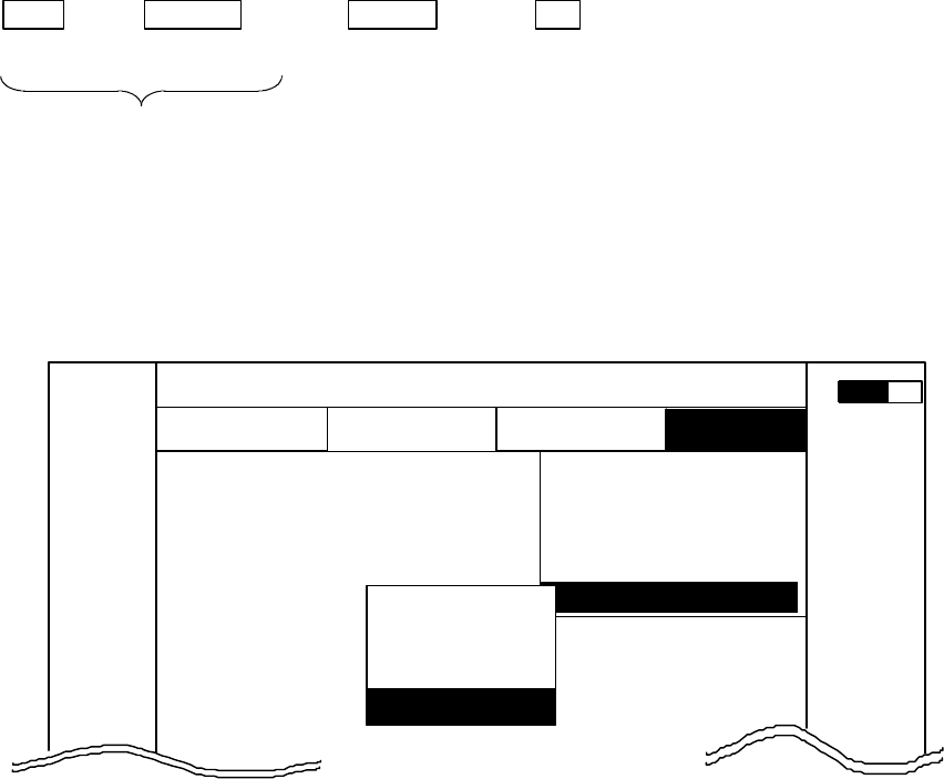
66
5.5.4.5 Changing the content of the setting (CUSTOM)
Note) Items in CUSTOM are for conducting settings and adjustments at the time of installation, which
need not be conducted normally.
-Common operations for CUSTOM
Use the up-down cursor keys to select CUSTOM after ”the common operations for the SETUP” menu,
and press either the "ENT" key.
MENU −> Left/Right −> Up/Down −> ENT
(Select SETUP) (Select CUSTOM)
Common operation for SETUP
When the above operations have been conducted, 4 items, namely "KEY ASSIGN", "PRESET1",
"PRESET2" and "ADJUST", are displayed beside the CUSTOM item.
Further explanation concerning the CUSTOM menu items will be done on the assumption that the
above "common operations for CUSTOM" have already been conducted.
CUSTOM
MARK WINDOW
SEL WIN
PICTURE
SYSTEM CHEC
K
.75
.25
HU S
L
NAV ECHO SETUP
SETUP
▼▼
▼
▼
▼
▼
0.23
NM
▼
A
KEY ASSIGN
PRESET1
PRESET2
ADJUST
▼
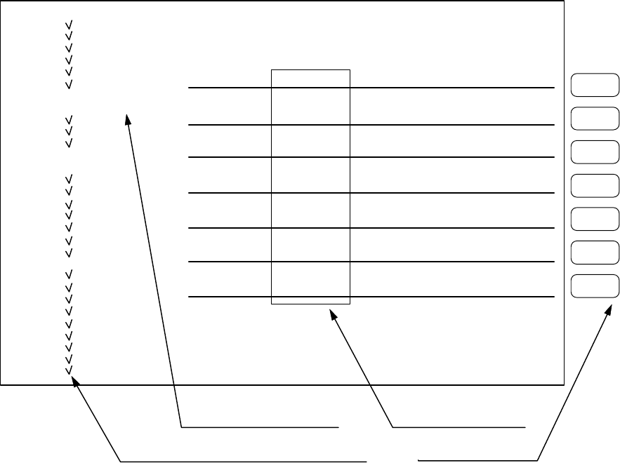
67
5.5.4.5.1 Changing the settings of soft keys (KEY ASSIGN)
Conducting alterations and new settings for the functions of keys with number displays of 1-7.
(1) Screen display for the setting
When KEY ASSIGN has been selected with the up-down cursor keys from among the CUSTOM items
and the "ENT" key is pressed, the setting screen is displayed. (See chart below)
(2) Selecting functions
Reverse the items to be set using the up-down cursor keys. (The items become reverse in accordance
with the moving cursor.)
(3) Key settings
(3)-1 Making new settings (Example 1)
For allocating the selected item to a soft key, press the key to be allocated. The selected item
will be displayed beside the key, which indicates that the setting has been conducted.
(3)-2 Changing the function of a key with an preset function (Example 2)
When the allocated key is pressed, its function will be altered to the one selected in (1) above and
the previous function will be canceled.
The current settings for SET1-4 will be displayed below NEXT. In order to switch the settings
SET1-4, use the right-left cursor keys. (Double settings (setting 1 item for more than 1 key) are
possible.)
1
5
6
7
4
3
2
KEY ASSIGNMENT
EBL1 EBL2 RINGS PPI
VRM1 VRM2 TUNE PPI/3D
VAR RNG FL EBL2 ST PPI/PPI
TRACK FL VRM2 ZOOM PPI/NAV
TARGET GZ SLEEP ALL PPI
SEL WIN OFF-C PICTURE ALL PPI2
NEXT NEXTNEXT NEXT
SET1 SET2 SET3 SET4
MARK □ EBL1
□ VRM1
□ EBL2
□ VRM2
□ FL EBL2
□ FL VRM2
□ HDG OFF
□ ///CSR
□ RINGS
□ VAR RNG
□ TARGET
□ +MK LINE
NAV □ MODE
□ GZ
□ OFF-C
□ SLEEP
ECHO □ TUNE
□ ST
□ TRACK
□ ZOOM
□ S/L
SETUP □ SEL WIN
□ PICTURE
□ PPI
□ PPI/3D
□ PPI/PPI
□ PPI/NAV
□ ALL PPI
□ ALL PPI2
□ NEXT
Key Groups
Move with up-down cursor Move with right-left cursor
Mark is displayed if the function set to some key. Operation panel Keys 1 - 7
Soft Key Setting Screen
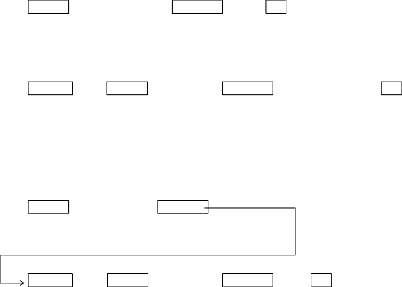
68
When settings are to be conducted for more than 1 key, repeat the operations (3)-1 to (3)-2. (Example 3)
(4) Completing the setting
After the setting has been finished, press the ENT key to exit from KEY ASSIGNMENT.
Example of an operation
(The process up to the selection of KEY ASSIGNMENT from the SETUP menu is omitted. Only the
process after the above chart will be described.)
Example 1) Altering OFF-C allocated to key 6 in setting 2 to HDG OFF.
Up/Down → 6 →ENT -------------------Key 6 altered from
Select HDG OFF The display beside key 6 Exit from OFF-C to HDG OFF
changes to HDG OFF KEY ASSIGNMENT
Example 2) Re-allocate SEL WIN to key 1 in setting 2.
Left/Right → Up/Down → 1 →---------------- ENT Key 1 in
setting 2
select SEL WIN SEL WIN is displayed Exit from is altered to SEL WIN
From SET1 beside key 1. KEY ASSIGNMENT
to SET2
Example 3) Alter key 1 in setting 1 from ST to HDG OFF and then reset key 1 in setting 2 as SEL WIN.
Up/Down → 6 --------- Key 6 altered from
Select HDG OFF The display beside key 6 ST to HDG OFF
changes to HDG OFF
Left/Right →Up/Down → 1 →ENT -------------Key
Select SEL WIN SEL WIN is displayed Exit from is altered to SEL WIN
From SET1 beside key 1. KEY ASSIGNMENT
to SET2
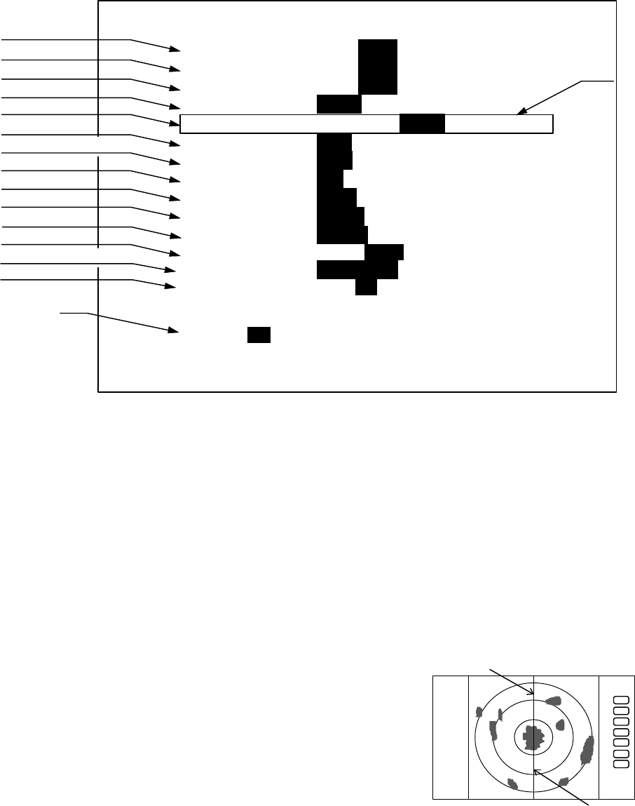
69
5.5.4.5.2 Changing the content of settings 1(PRESET1)
(1) When PRESET1 is selected from CUSTOM items and the "ENT" key is pressed, the
PRESET1 screen (See chart below) appears.
(2) Select items with up-down keys and contents with left-right keys.
The selected items will be enclosed by square frames and the contents will appear in reversed
display. (a)
Repeat this operation when multiple settings are to be made.
(3) After the setting is completed, exit from the PRESET1 screen with the "ENT" key.
Note) The contents will be displayed in (b) together with the numbers selected in P TABLE.
a) Heading Flash Each revolution of the antenna turns the heading marker on
and off.
b) Stern Mark Display/non-display of the stern line
c) North Mark Display/non-display of the north mark
d) ST'BY screen Setting the screen display in stand-by
NAVI: Navigation Data screen
NOR: Normal screen
e) Buzzer Volume Setting the volume of the buzzer
f) VRM Unit Setting VRM unit
NM: Nautical mile
KM: Kilometer
SM: Statute mile
g) Water temperature Setting water temperature
unit
°C: Celsius
F: Fahrenheit
h) Depth Unit Setting Depth unit
M: Meter
a) Heading Flash
b) Stern Mark
c) North Mark
d) ST'BY screen
e) Buzzer Volume
f) VRM Unit
g) Water temperature
h) Depth Unit
i) EBL Mode
j) WayPoint Mode
k) Heading Input
l) Heading Type
m) Cursor position
n) TX Pulse
PRESET1
HM FLSH ON OFF
STERN M ON OFF
NORTH M ON OFF
ST‘BY NAVI NOR
BUZ VOL OFF LOW HIGH
RM UNIT NM KM SM
TEMP °C F
DEPTH M FT FM
EBL BRG REL TRUE MAG
WP BRG TRUE MAG
HEAD INPUT NMEA SIN/COS 12BIT 10BIT
HEAD TRUE MAG
+MK MODE DIST/BRG LAT/LON
P TABLE 0 1 2
.5 .75 1.5 3 6
P TABLE 1 SHORT 0001 1
LONG 01 1 2 2
(a)
(b)
Heading Marker
Stern Marker
.75
.25
HU
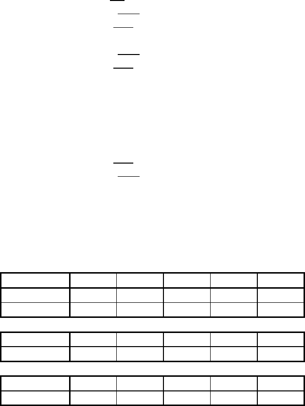
70
FT: Feet
FM: Fathom
i) EBL Mode Setting Mode of EBL
REL: Relative bearing from HM
TRUE: True bearing
MAG: Magnetic bearing
j) WayPoint Mode Setting WayPoint bearing mode
TRUE: True bearing
MAG: Magnetic bearing
k) Heading Source Setting Heading source;
NMEA
SIN/COS: Compass Data with SIN/COS signal
12BIT: Compass Data with 12bits serial signal
10BIT: Compass Data with 10bits serial signal
l) Heading Type Heading Information Type setting
MAG: Magnetic bearing
TRUE: True bearing
m) Cross cursor position display Mode
DIST/BRG: Range and Bearing indication
LAT/LON: Latitude and Longitude indication
n) Transmitting pulse width Pulse setting for Rang (Note: )
Note: P TABLE PUSLE TYPE 0.5NM 0.75NM 1.5NM 3NM 6NM
P TABLE 0 SHORT 00001
LONG 00112
P TABLE 1 SHORT 00011
LONG 01122
P TABLE 2 SHORT 00111
LONG 11222
Note1: Pulse width 0 : 0.12uS, 1 : 0.3uS, 2 : 0.8uS
Note2: The pulse width for 0.125 to 0.25NM Ranges are always 0.12us.
Note3: The pulse width for 12NM and 24NM Ranges are always 0.8us.
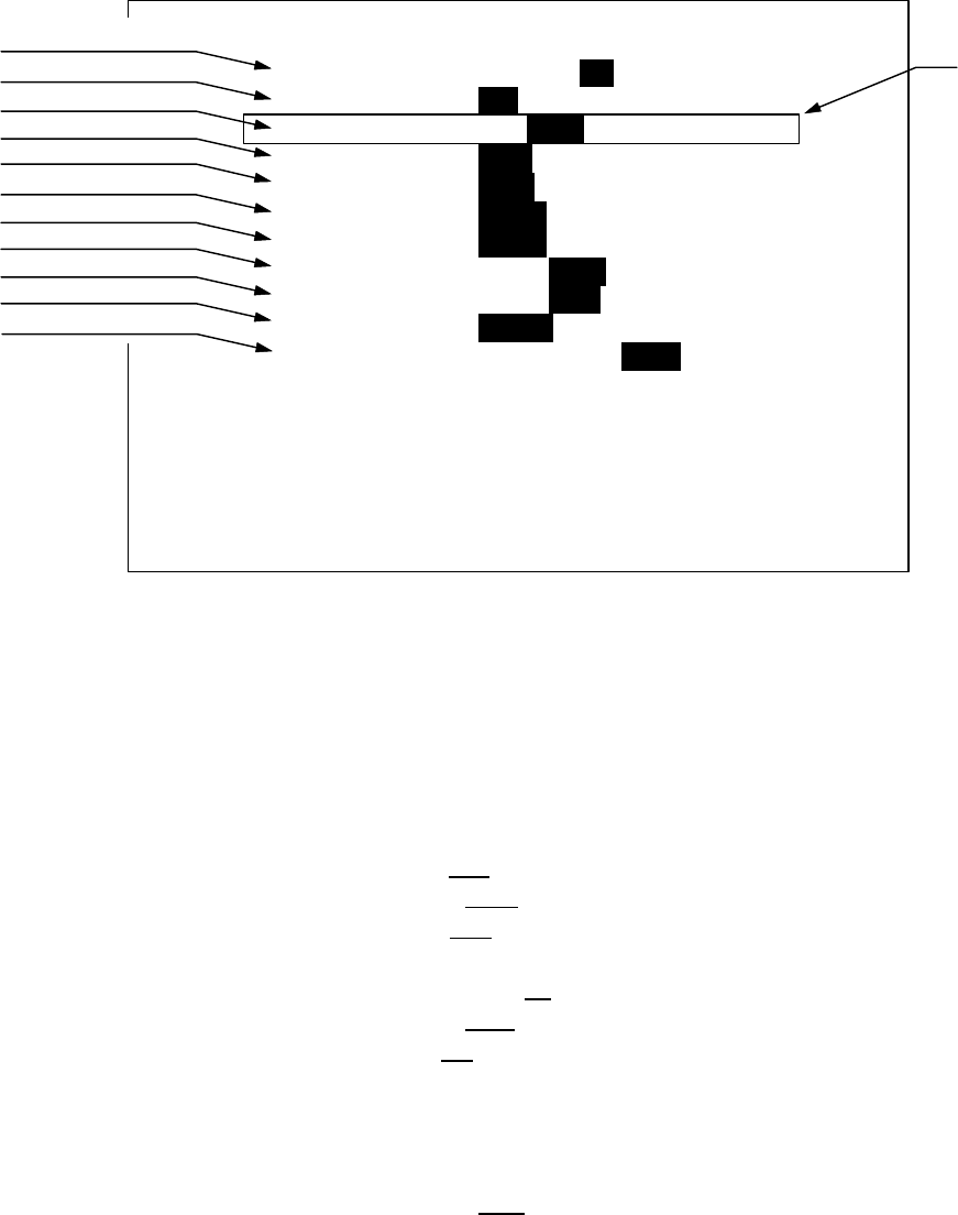
71
5.5.4.5.3 Changing the content of settings 2 (PRESET2)
Refer to the section, “Changing the content of setting 1(PRESET1)”.
a) Guard Zone Level Guard Zone Detection Level setting
1: High Sensitivity, .. 7: Big Target Only
b) Guard Zone Mode Guard Zone Detection Mode setting
IN: Detect Target in
OUT: Detect Target dissapear
c) Hold Hold the radar picture for 30 seconds after switch to ST'BY
The EBL and VRM can be used in HOLD state.(Note1: )
d) Display Unit Mode Display Unit Operation Mode setting
RDR: Radar mode(normal)
MONI: Monitor mode(for slave display use)
NAV: Navigation mode(for DATA indicator use)
e) External Buzzer External Buzzer control setting
OFF: Buzzer off
CONT: Continuous tone
INT: Intermittent tone
f) Bearing pulse/rot.(IN) Change the setting when connected to the other type of radar
g) Bearing pulse/rot.(OUT) Change the setting when connected to the other type of radar
h) Built-in simulator switch for Demonstration
i) Interference Rejection Reject the interference from the other radar
OFF: IR OFF
IR1: ON level 1
IR2: ON level 2
(a)
a) Guard Zone Level
b) Guard Zone Mode
c) Hold
d) Display Unit Mode
e) External Buzzer
f) Bearing pulse/rot(IN)
g) Bearing pulse/rot(OUT)
h) Built-in Simulator
i) Interference Rejection
j) Ship's Speed
k) Indication Language
PRESET2
GZ LVL 1 2 3 4 5 6 7
GZ MODE IN OUT
HOLD ON OFF
DISPLAY RDR MONI NAV
EXT BUZ OFF CONT INT
IN P/R 1080 1024 2048 4096 360
OUT P/R 1080 1024 2048 4096 360
DEMO ON OFF
IR OFF IR1 IR2
SPD SET NMEA MANU 0.0KT
LANGUAGE CHI DAN ENG FRE GER
GRE ITA JPN KOR NOR
POR RUS SPA SWE TUR
PRESS ENTER KEY TO RETURN
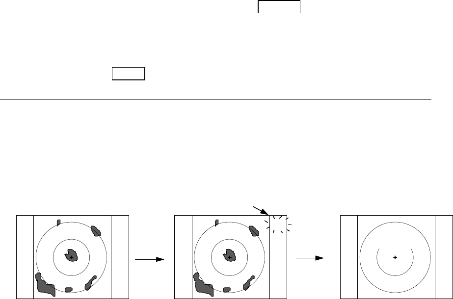
72
j) Ship's Speed Own ship's speed setting
NMEA: Data input from NMEA port
NAMU: Set ship's speed with manual
Set the Speed with control knob.
k) Indication Language Select the language for MENU and SOFT KEY( Note2: )
Note1:
HOLD function POWER = POWER key to press
HOLD is function which you want to hold the currently displayed radar screen conditions while
standby state. After finished operation such as EBL, VRM about 30 seconds, the screen return to
standby screen.
Setting HOLD POWER (Operation)
▽ ▽
(Under Tx) ------------------------------------------- △<―――――Under HOLD
mode―>△<―――――ST’BY DISPLAY―――
Turn to transmission off
EBL,VRM operation:X seconds X+30seconds
(Time used)
NOTE) EBL and VRM function is usable in HOLD state.
Note2:
15 languages
CHI : Chinese KOR : Korean
DAN : Danish NOR : Norwegian
ENG : English POR : Portuguese
FRE : French RUS : Russian
GER : German SPA : Spanish
GRE : Greek SWE : Swedish
ITA : Italian TUR : Turkish
JPN : Japanese
ST‘B
HOLD
“HOLD” is displayed and blink
Tx OFF
X+30
Setting
HOLD
EBLs and VRMs can be used
for measuring target data.
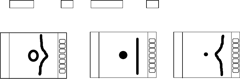
73
5.5.4.5.4 Changing the content of settings (ADJUST)
The items in the ADJUST menu are ones that need adjustment at the time of installation. The
settings need not normally be altered.
(1) Adjusting distance (TIMING ADJ)
This adjustment is necessary to adjust the distance on the radar screen to the actual distance.
(1) In preparation for adjusting the distance, the following adjustments are to be conducted.
First, set the radar range to 0.25 NM, FTC to minimum, and GAIN to optimum. Then adjust STC
until the pulse generated by your own radar appearing at the center of the screen is clearly
recognized as a round dot.
(2) Adjusting the distance.
(2)-1 Select ADJUST by "common operations for CUSTOM", use up-down cursor keys to select
TIMING ADJ from among the pull-down display items and press the "ENT" key.
(2)-2 As the distance adjustment screen is displayed, adjust timing until the center dot looks as
(b) with the control knob. If there is a linear target such as a bridge or breakwater, adjust
timing until the target appears straight in the screen.
(2)-3 When the adjustment is finished, press the "ENT" key to exit from the distance
adjustment screen.
Up/Down →ENT →Control knob →ENT
select TIMIG ADJ Timing adjustment finished
(2) Adjusting angle (HEAD ADJ)
This adjustment is necessary to adjust the head direction on the screen to the actual direction of
the ship.
(1) In preparation for adjusting the angle, the following adjustments are to be conducted.
(1)-1 Find one small target within a 0.5 to 1.5 NM range which, lying in the bow direction, can be
detected with eyes and is clearly visible in the radar screen.
(1)-2 Measure the bearing of this target from the bow direction using a compass. Let it be θc.
(1)-3 Measure the bearing of the above target in head up (HU) mode using EBL. Let it be θr.
(1)-4 Calculate the following:
θc - θr: if θc is greater than θr
360 - ( θr - θc ) : if θr is greater than θc
a) Too far b) Correct c) Too shrunk
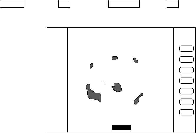
74
This is the azimuth error of your radar at installation. If θc and θr are equal, the
adjustment described below is unnecessary.
(2) Adjustment method
(2)-1 Select ADJUST by "common operations for CUSTOM", use the up-down cursor keys to
select HEAD ADJ from among the pull-down display items and press the "ENT" key.
(2)-2 As the distance adjustment screen is displayed, set the value to the azimuth error you
have calculated above with the control knob.
(2)-3 When the adjustment is finished, press the "ENT" key to exit from the distance
adjustment screen.
Up/Down −> ENT −> Control knob −> ENT
Select HEAD ADJ. Set a value to .
(3) Adjusting tuning circuit (TUNING CAL)
Normally you do not need to make this adjustment. This adjustment may necessary to ensure
that the automatic tuning circuit operate at its best operating point. However, if sensitivity is poor or
there is any symptom suggesting improper tuning, you may need to adjust this circuit following the
procedure below.
(1) Choose several stable video images in the 3 NM range or more.
(2) Select ADJUST by "common operations for CUSTOM", use the up-down cursor keys to select
TUNING CAL. from among the pull-down display items and press the "ENT" key.
(3) As the tuning circuit adjustment screen(TUNING CALIBRATION) is displayed, select AUTO
with up-down cursor key.
(4) While watching video images, adjust until echoes are clearly visible with the control knob.
(5) Select MANUAL with the down cursor key.
(6) Adjust until echoes are clearly visible with the control knob. This set status is middle value of
manual tuning.
HEAD DIRECTION ADJUSTMENT
ADJUST WITH CONTROL KNOB
PRESS ENTER KEY TO RETURN
358.8°
HEADING Adjustment
3
1
HU
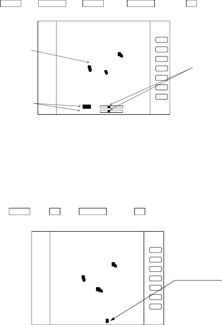
75
(7) When the adjustment is finished, press the "ENT" key to exit from the TUNING
CALIBRATION screen.
Operate of (3) to (7)
Up/Down −> Control knob −> Up/Down −> Control knob −> ENT
Select AUTO Adjust tuning Select MANU Adjust tuning
(4) Adjusting antenna height (ANTENNA)
Depending on the position at which the antenna is installed, it may be necessary to make the
following correction. (Consult Anritsu or an Anritsu distributor for details.)
(1) Select ADJUST by "common operations for CUSTOM", use the up-down cursor keys to select
ANTENNA from among the pull-down display items and press the "ENT" key.
(2) As the adjustment screen is displayed, using the control knob to choose your desired value from
1 to 9.
(3) Press the "ENT" key to exit from the adjusting antenna height screen.
Up/Down −> ENT −> Control knob −> ENT
Select ANTENNA Choose value Complete
Adjust with control knob
Select with up-down
cursor key
Echo remain.
TUNING CALIBRATION
READ OPERATION MANUAL
SELECT ITEM WITH ∧∨ KEY
TUNE WITH CONTROL KNOB
PRESS ENTER KEY TO MEMORY
AUTO
MANUAL
3
1
HU
Adjust with Control knob
STC CURVE ADJUSTMENT
ADJUST WITH CONTROL KNOB
PRESS ENTER KEY TO MEMORY
STC CURVE 5
3
1
HU
ANTENNA Adjustment

76
(5) Setting automatic GAIN circuit (AUTO GAIN)
Here, you set the automatic and manual gain level. Normally, adjust this setting to be slight the
noise echo appears on the screen in AUTO mode.
(1) Select ADJUST by "common operations for CUSTOM", use the up-down cursor keys to select
AUTO GAIN from among the pull-down display items and press the "ENT" key.
(2) As the adjustment screen is displayed, using the control knob to choose your desired value from
1 to 30.
(3) Press the "ENT" key to exit from the adjustment screen.
Up/Down −> ENT −> Control knob −> ENT
Select AUTO GAIN Choose value Complete
(6) Setting automatic STC circuit (AUTO STC)
Here, you set the automatic STC and automatic FTC level. Adjust this setting to be slight sea
clutter appears on the screen, when you observe a small target (ex. Small buoy).
(1) Select ADJUST by "common operations for CUSTOM", use the up-down cursor keys to select
AUTO STC from among the pull-down display items and press the "ENT" key.
(2) As the adjustment screen is displayed, using the control knob to choose your desired value from
1 to 16.
(3) Press the "ENT" key to exit from the adjustment screen.
Up/Down −> ENT −> Control knob −> ENT
Select AUTO GAIN Choose value Complete
(7) Setting HARBOR STC circuit (HARBOR)
Here, you set the HARBOR STC level. Adjust this setting to be slight sea clutter appears on the
screen, when you observe the land in a bay area at short-distance range.
(1) Select ADJUST by “common operations for CUSTOM”, use the up-down cursor keys to select
HARBOR from among the pull-down display item and press the “ENT” key.
(2) As the adjustment screen is displayed, using the control knob to choose your desired value from
1 to 16.
(3) Press the “ENT” key to exit from the adjustment screen.
Up/Down −> ENT −> Control knob −> ENT
Select HARBOR Choose value Complete
77
CHAPTER 6. MAINTENANCE AND INSPECTION
Most of maintenance of this radar should be referred to qualified personnel. If radar
has any problem, contact your dealer and tell us that problem.
There are high voltage circuit inside of this radar.
Do not attempt to open the rear cover of display unit
or disassemble internal parts. When you open the
radome, power must be off.
Even power switch is OFF, this radar is still sup-
plied power inside.
The followings table shows the maintenance by user. Please check periodically.
Tab. 6-1 Maintenance
*: Use grease for plastics for RA775UA. If you use other type of grease(not for plastics), it
may break antenna
Concerning Consumable
The radar uses consumable as listed below that require periodic replacement.
(1) Magnetron
This part is mounted in the scanner unit. If distant echo images have be-
come less visible, the magnetron probably may have degraded. In such a case,
replace it. Consult your distributor for replacement of this part.
Period of the replacement : 3000hour(typ.) (500hour guarantee)
(2) LCD back-light
This part is mounted in the display unit. If the display screen is ex-
tremely dark and its illumination cannot be corrected by adjusting brightness,
the LCD back-light may be faulty or may have burnt out. In such a case, replace
it. Consult your distributor for replacement of this part.
Period of the replacement : 15000hour(typ.) (1000hour at 0℃)
Inspection Interval Inspection Item Method of Inspection and Maintenance
3-6 months Rust and looseness
in scanner unit Check whether the scanner’s fitting bolts are
corroded or less.
Display screen of
LCD display Clean filter and LCD screen surfaces with a soft
and wet cloth.
6-12 months Grease* application
to antenna drive
gear
Apply an even coating of grease* to the entire
surface of the antenna drive gear with a spatula
or brush.
Check for contact of
connectors Check whether connectors are contacted prop-
erly. If any connector is improperly contacted or
stained, correct it by using a contact restoring
chemical agent or by polishing or replace with a
new one if necessary.
!WARNING
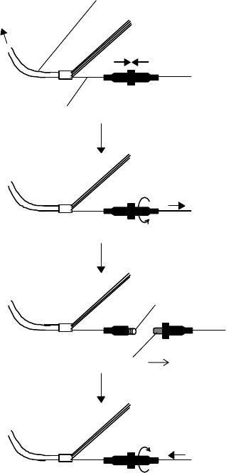
78
(3) Fuse
The fuse is built in
the power supply cable. If
the fuse appears to be
blown, check the fuse. If
blown, replace it following
the procedure shown in
Fig.6-2.
Push
Power supply cable
Wire(White)
Turn counterclockwise
and pull
Fuse
Spring
Push and turn clockwise
Replace new fuse
To display unit
Fig. 6-2 Method for replacing fuse
79
CHAPTER 7. TROUBLESHOOTING
This chapter explains how to identify trouble locations when the radar is found faulty
and how to request repair.
It happens any disorder, keep pressing POWER key for 3 sec. to power off. Then wait
over 10 sec., when you power on again.
If you find the radar is faulty, check it the following procedure described below. If you
find as a result of inspection that the fault cannot be repaired on board, contact your dis-
tributor or Anritsu for repair.
For faster service, please let us know about followings when you request repair:
(1) Ship's name, place of anchorage, allowable repair period or time
(2) Radar type (This radar is RA775UA.)
(3) Manufacturing number (indicated on the back of the display unit)
(4) Fault symptoms and inspection results
There are high voltage circuit inside of this radar.
Do not attempt to open the rear cover of display unit
or disassemble internal parts. When you open the
radome for installation, power must be off.
Even power switch is OFF, this radar is still sup-
plied power inside.
This chapter explains how to identify trouble locations when the radar is found faulty
and how to request repair.
●7.1 Fault Diagnosis by Self-check
The radar incorporates a failure diagnostic function (called "self-check") to diagnose
faults by the equipment itself.
Please refer to "5.5.4.4 Fault Diagnosis by Self Check (SYSTEM CHECK)
"
and check
whether there is any fault in your radar.
!WARNING

80
●7.2 Inspecting Each Part
When you have finished self-check, inspect each part of the radar according to Tab.7-1.
Tab. 7-1 Troubleshooting
Symptom Cause Corrective action
(1) Radar cannot be powered on. Power cable is disconnected. Connect power cable correctly.
Power supply voltage is off
specified value Use Specified power supply. (See
Section 3.2)
Fuse in power cable is blown. Replace fuse. (See Chapter 6)
(2) Nothing is displayed although
radar is powered on. Brightness or contrast are im-
properly adjustment. Use BRIL key to adjust. (See
Section 5.3.)
LCD is faulty. Contact your dealer.
(3) Screen is dark. Brightness is improperly ad-
justed. Use BRIL key to adjust. (See
Section 5.3.
Backlight is faulty. Contact your dealer.
(4) Video does not appear al-
though characters are displayed. Interconnecting cable is out of
place. Connect interconnecting cable
correctly.
(5) Echo image on screen differs
from actual image. Ship’s heading is incorrectly set. Set ship’s heading correctly. (See
Section 5.5.4.5.4)
Timing adjustment is incorrectly
set. Set timing adjustment correctly.
(See Section 5.5.4.5.4)
(6) Echo images are blurred. GAIN, STC, or FTC is improp-
erly set. Adjust. (See Section 5.3.6 to
5.3.8.)
Magnetron has degraded. Contact your dealer.
(7) Too much noise. Radar is not tuned correctly Adjust TUNE. (See Section
5.5.3.4)
Radar is not grounded to earth. Connect grounding wire. (See
Section 3.4 to 3.6.)
(8) Not responded when key is
pressed. Panel keys are not contacting. Contact your dealer.
Power supply circuit is faulty. Contact your dealer.

81
CHAPTER 8. PRODUCT SPECIFICATIONS
●8.1 General
Type: RA775UA
Power supply voltage and power consumption
Power supply voltage: 24Vdc (nominal)
(10.2 to 41.6 Vdc)
Power consumption: 55 W or less
Distance range: 0.125 to 24 NM, 9 ranges
(Continual variable range also
possible)
Distance resolution: Within 30 m
Distance accuracy: Better than 0.9% of maximum
range of the scale in use, or 8m,
whichever is the greater
Minimum detecting distance: Within 30 m
Bearing resolution: Within 7.5°
Bearing accuracy: 1° or less
Warm-up time: 2 minutes
Environment conditions
Ambient temperature range (S/U): -25 to 55 °C
(D/U): 0 to 55 °C
Humidity: 93% RH at +40 °C
Vibration: (S/U): 3mm(300∼500rpm),
1.2mm(500∼1500rpm),
0.3mm(1500∼3000rpm)
14.7m/s2(1.5G) Resonance test
(D/U): 3mm(300∼500rpm)
0. 75mm(500∼1500rpm)
0.2mm(1500∼3000rpm)
Wind resistance: 100 knots (max.)
Waterproof standard: (D/U): IPX-5
(S/U): CFR-46
Interconnecting cable: 30 m (max.)
Noise: 65 dB or less
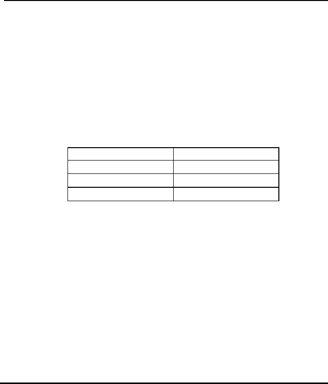
82
●8.2 Scanner Unit
Type: RB714A
Antenna type: Parabolic
Antenna characteristics
Beam width (horizontal): 6.0° ± 1.0°
Beam width (vertical): 25° (typ.)
Pulse width and peak power output: Pulse width(us) Peak Power(kW)
0.12 ± 0.02 1.5(±50%)
0.3 ± 0.05 2.0(±50%)
0.8 ± 0.1 2.0(±50%)
Radio wave type and frequency: P0N, 9445 ± 30 MHz
Antenna revolution: 24 rpm ± 20%
Transmit/receive switching: Magic T and limiter type
Intermediate frequency: 60 MHz
(logarithmic amplifier)
Noise figure: 6.5 dB or less
●8.3 Display Unit
Type: RF718A
Indication system: PPI, PPI+semi-3D,
Split radar range
Indicator: 10-inch monochrome LCD
640 x 480 dots
Monochrome 4 gray levels
Cursor Control: Analog cursor key
and rotary encoder
VRM: 2 lines (One line can be offset.)
Unit of distance can be
selected from NM, KM, and
SM.
EBL: 2 lines (One line can be offset.)
Display modes: HU, HS, NU, CU, and TM
Off-center: Can be 100% off-centered over
the full range.

83
Guard zone: Can be set at any desired
distance and angle in any
desired width. IN and OUT
modes are available.
Stretch: 2 modes
Echo track: 15, 30 sec, 1, 3, 6 min. and
Continuous.
Other functions: Interference rejection, Zoom,
Sleep mode,
Hold mode, Course error
display,
Parallel cursors, Stern marker,
and Navigation data display
mode
Panel brightness: 4 levels
Language support: Chinese, Danish, English,
French, German, Greek,
Italian, Japanese, Korean,
Norwegian, Portuguese,
Russian, Spanish, Swedish,
and Turkish
●8.4 External Interface
NMEA0183: 2 channels
(One standard channel;
Optional cable is required for
2nd-channel connections)
L / L GGA, GLL, RMA, RMC
Heading HDT, HDG, HDM, HSC,
VHW, VTG
Speed VHW, VTG, RMA, RMC
Way point RMB, BEC, BWC,
BWR, BER, BPI
Depth DBT, DPT
Course error RMB, XTE
Seawater temperature MTW
Others (using optional cable):
External buzzer control output, Auxiliary indicator connecting signal
output and input, Bow direction signal input(SIN/COS signals), and
compass interface (10/12 bits serial)
●8.5 Standard set
Display unit 1
Scanner unit 1
Display cover 1

84
Fuse 1 set
Interconnecting cable 1 (10m)
Power supply cable 1 (2m)
M10 hexagonal bolt 4 sets
●8.6 Options
Interconnecting cable (15, 20, and 30 m)
Flush-mount installation kit
Junction box for external connection (with cable 1.5m)
Option connector kit 249J153058
●8.7 External dimensions and weight
See APPENDIX
●8.8 External Interface
X1 Connector for Option
pin No. Name function
1NMEA2-A NMEA ch2 data input(A)
19 NMEA2-B NMEA ch2 data input(B)
2GND
20 EXBUZ+ Output for External Buzzer
3EXBUZ- Output for External Buzzer
controlled ship's power output
21 VIDEO_IN Video input for Monitor operation
0 to -1V negative video, Zi = 50ohm
4VIDEO_OUT Video output for External Monitor
0 to -1V negative video, Zo = 50ohm
22 GND
5TRIG_IN Trigger signal input for Monitor operation
0 to 5V positive pulse, rising edge
23 TRIG_OUT Trigger output for External Monitor
0 to 5V positive pulse, rising edge
6SHF_IN Heading signal input for Monitor operation
0 to 5V negative pulse, falling edge
24 SHF_OUT Heading signal output for External Monitor
0 to 5V negative pulse, falling edge
7AZI_IN Bearing Pulse input for Monitor operation
0 to 5V positive pulse, rising edge
25 AZI_OUT Bearing Pulse output for External Monitor
0 to 5V positive pulse, rising edge
8GND
26 GYRCK+ Gyro Interface clock(+) input
9GYRCK- Gyro Interface clock(-) input
apply 5V pulse between (+) and (-), isolated
27 GYRDT+ Gyro Interface data(+) input
10 GYRDT- Gyro Interface data(-) input
apply 5V pulse between (+) and (-), isolated
28 GND

85
X1 Connector for Option(continued)
pin No. Name function
11 MARK_I External Marker signal input, ex) Radar Buoy
negative video, 0 to -1V Zi = 50ohm
29 +12V External interface power, 100mA max.
12 SIN Compass Interface for SIN/COS type
30 COS Compass Interface for SIN/COS type
13 REF Compass Interface for SIN/COS type
SIN/COS signal: SIN = REF+/-1V, COS = REF+/-1V
31 -- not used
14 GND
32 NMEA_OUT NMEA data output, ex) MOB data, TARGET data
24W160941
ANRITSU CORP.
DEP
APPLICATION REVISIONS
A
B
C
D
E
DRAWING NO.
24W160941 -00
NOTEFINISHMATERIALDESCRIPTIONPART NO.QTY
TITLE
RA775UA GENERAL SYSTEM DIAGRAM
SCALE
/
APPROVED BY DRAWN BY
TRACED BY CHECKED BY
ITEM
SCANNER
UNIT
RB714A
DISPLAY
UNIT
RF718A
DC Power
Supply
10.2∼41.6Vdc
(Option I/F)
Note 1. 点線はオプション
: Option
NMEA I/F
for
Navigation
Inter-Connection Cable
(10m standard)
Power supply Cable
7 July H.Iida
7 July H.Iida
7 July Y.Aso
24W160939
ANRITSU CORP.
DEP
APPLICATION REVISIONS
A
B
C
D
E
DRAWING NO.
24W160939 - 00
NOTEFINISHMATERIALDESCRIPTIONPART NO.QTY
TITLE
RA775UA INTER-CONNECTION DIAGRAM
SCALE
/
APPROVED BY DRAWN BY
TRACED BY CHECKED BY
ITEM
SCANNER
UNIT
DISPLAY
UNIT
SCAN PCB (X1)
1 17 VIOLET +250V
4 17 YELLOW GND
2 17 BLUE +24V
5 RED DAT
43 ORANGE3 +12V
7 BROWN BP/SHF
6 Braid of RED DAT-R
No
.
Color Function
POWER PCB (X3)
1
2
3
4
5
6
7
8
9
10
11
12
13
14
15
16
No
.
17 VIOLET
17 BLUE
43 ORANGE
Color
17 YELLOW
Braid of RED
RED
BROWN
Braid of BROWN
GRAY
Braid of GRAY
Function
+250V
+24V
+12V
GND
DAT-R
DAT
NC
BP/SHF
BP/SHF-R
V/TRG
NC
NC
NC
V/TRG-R
NC
NC
9 GRAY V/TRG
8 Braid of BROWN BP/SHF-R
10 Braid of GRAY V/TRG-R
7 July H.Iida
7 July H.Iida
7 July Y.Aso
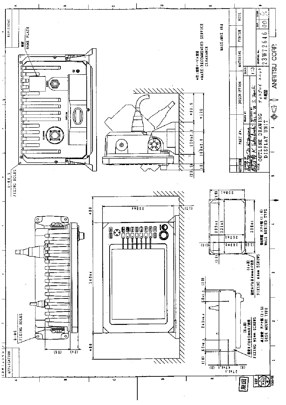
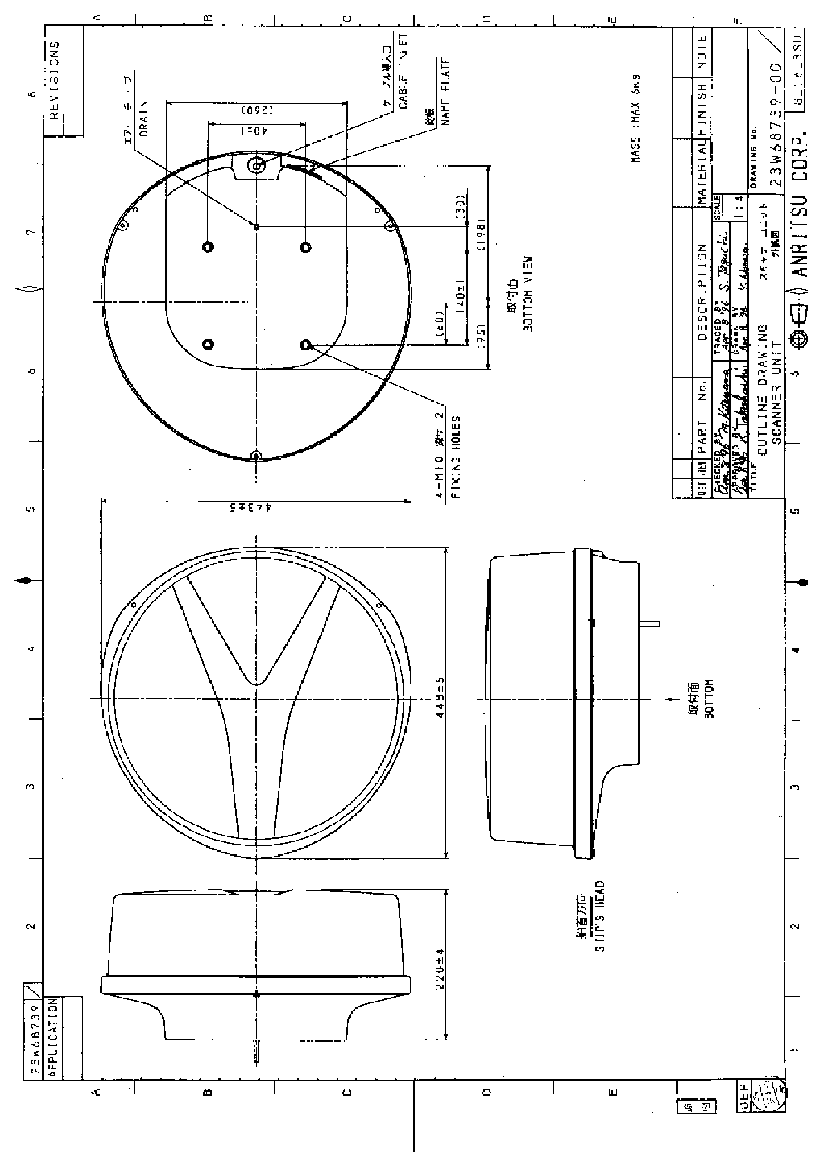
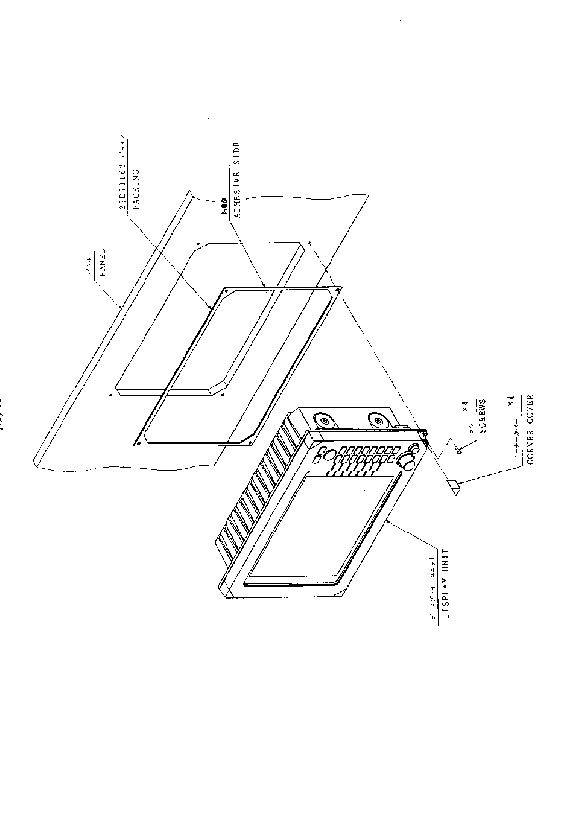
Index
A
Adjustment
Distance ....................................73
Angle .........................................73
Tuning.......................................74
Antenna height..........................75
Automatic gain..........................76
Automatic STC..........................76
ALL PPI Screen...................................62
ALL PPI/PPI Screen............................62
B
Bearing scale.......................................25
Brightness ...........................................28
Brightness of Panel...................28
Buzzer..................................................69
C
Changing setting (CUSTOM)..............66
Check box ............................................67
Continual variable range (VAR RNG).36,48
Contrast...............................................28
Course error (XTE)..............................27
Cross cursor (+)...................................25
D
Display modes (MODE).......................36,50
E
EBL ...................................................33,44
Bearing of EBL (EBL BRG).......69
Echo Menu...........................................54
F
False echoes.........................................5
FL VRM, FL EBL ................................34,45
FTC ...................................................32,55
G
Gain ...................................................31,54
Guard zone (GZ)..................................36,51
Guard zone mode (GZ MODE)..71
Guard zone level (GZ LVL) .......71
H
Heading marker ..................................6
Heading Off (HDG OFF)...........36,47
Heading blink (HM FLSH)........69
Heading information (HEAD)...27
Hold (HOLD).......................................71
L
Language.............................................71
M
Mark Line............................................49
Menu bar.............................................43
Man Over Board (MOB) ......................32
MOB Screen.........................................63
Monitor operation (DISPLAY).............71
N
Nav (Navigation) Menu.......................50
Navigation screen................................27
North mark (NORTH M)....................6,69
O
Off-center (OFF-C)..............................37,52
Option.................................................84
P
Parallel cursor (///CSR).......................36,47
PPI Screen...........................................60
PPI/NAV Screen..................................62
PPI/PPI Screen....................................61
PPI/SEMI3D Screen............................61
Pulse table (P TABLE)........................69
R
Radar interference..............................6
Radar screen.......................................25
Range..................................................30
Range rings (RINGS)..........................36,48
Range ring interval...................48
Reverse screen ....................................40,63
S
Semi-3D ..............................................41,61
Sleep (SLEEP).....................................52
Speed (SPEED, SPD SET)..................71
ST'BY..................................................28
ST'BY NAV screen..............................69
STC ..................................................31,55
Stern marker (STERN M)...................69
Stretch (ST).........................................39,55
Switching the screen (SEL WIN)........40,63
System check .....................................64
T
Target (TARGET)................................49
Track (TRACK)...................................39,56
Tune ..................................................38,55
Tune meter .........................................25
V
VAR RNG............................................36,48
VRM ..................................................33,45
Unit of VRM (RM UNIT)..........69
W
Way point (WAYP)..............................27
Bearing of Way point (WP BRG) ... 69
X
XTE ..................................................27
Z
Zoom (ZOOM) .....................................39,57