AnyDATA DTS-800CDK CDMA Development kit DTS-800 User Manual
AnyDATA Corporation CDMA Development kit DTS-800
AnyDATA >
Contents
- 1. Service manual
- 2. User Manual
User Manual

DTS-800 CDK User Manual
Application Information
01-DTS800 CDK-1 X1
April 23, 2001
AnyDATA.NET Inc.
Hanvit Bank B/D 7F
Byulyang-dong Kwachon
KOREA
Τελ) 82−2−504−3360
Φαξ) 82−2−504−3362

01-DT800-1 X1 AnyDATA.NET Proprietary – Use Subject to
Restrictions ii
AnyDATA.NET Inc.
Ηανϖιτ Βανκ Β/∆ 7Φ
Βψυλψανγ−δονγ Κωαχηον
KOREA
Copyright 2001 AnyDATA.NET Inc..
All rights reserved. Printed in the Republic Of KOREA.
All data and information contained in or disclosed by this document are confidential and proprietary
information of AnyDATA.NET Inc., and all rights therein are expressly reserved. By accepting this
material, the recipient agrees that this material and the information contained therein are held in
confidence and in trust and will not be used, copied, reproduced in whole or in part, nor its contents
revealed in any manner to others without the express written permission of AnyDATA.NET Inc..
AnyDATA.NET Proprietary : Restricted Distribution. This document contains critical information about
AnyDATA.NET products and may not be distributed to anyone without permission of AnyDATA.NET
Inc. All data and information contained in this document are proprietary and confidential information of
AnyDATA.NET Inc. No part of this document may be reproduced, in any form or any means without
written permission of AnyDATA.NET Inc.
Although the information in this document has been carefully reviewed and its believed to be reliable.
AnyDATA.NET Inc. does not assume any liability arising out of the application or use of any product
described herein, Neither does it convey any license under its patent rights nor rights of others.
Send Technical Questions to :
paiton@AnyDATA.NET
DTS-800 CDK Reference Manual Application Information
01-DT800 CDK-1 X1
Απριλ 23, 2001
Introduction
Τηε Χ∆ΜΑ δεϖελοπµεντ κιτ (Χ∆Κ −800) ισ δεσιγνεδ φορ τηε τεστ ανδ σιµυλατιον οφ τηε Χ∆ΜΑ
ωιρελεσσ δατα χοµµυνιχατιονσ. Υσερ χαν χοννεχτ τηε δεϖελοπµεντ κιτ το ψουρ ΠΧ ορ
Νοτεβοοκ ανδ εασιλψ τεστ τηε ωιρελεσσ χοµµυνιχατιονσ. Υσερ χαν υσε τηισ το δεϖελοπ
ψουρ αππλιχατιονσ σοφτωαρε εϖεν βεφορε υσερ’σ οων ηαρδωαρε ισ ρεαδψ. Ιτ αλσο χαν βε
υσεδ ασ α δεβυγγινγ δυρινγ υσερ’σ ηαρδωαρε τεστ.
01-DT800-1 X1 AnyDATA.NET Proprietary – Use Subject to
Restrictions iii
Disclaimer and Limitation of Liability
Ανψ∆ΑΤΑ.ΝΕΤ Ινχ. ασσυµεσ νο ρεσπονσιβιλιτψ φορ ανψ δαµαγε ορ λοσσ ρεσυλτινγ φροµ τηε
µισυσε οφ ιτσ προδυχτσ. Ανψ∆ΑΤΑ.ΝΕΤ Ινχ. ασσυµεσ νο ρεσπονσιβιλιτψ φορ ανψ λοσσ ορ
χλαιµσ βψ τηιρδ παρτιεσ, ωηιχη µαψ αρισε τηρουγη τηε υσε οφ ιτσ προδυχτσ.
Ανψ∆ΑΤΑ.ΝΕΤ Ινχ. ασσυµεσ νο ρεσπονσιβιλιτψ φορ ανψ δαµαγε ορ λοσσ χαυσεδ βψ τηε
δελετιον ορ λοσσ οφ δατα ασ α ρεσυλτ οφ µαλφυνχτιονσ ορ ρεπαιρσ.
Τηε ινφορµατιον δισχλοσεδ ηερειν ισ τηε εξχλυσιϖε προπερτψ οφ Ανψ∆ΑΤΑ.ΝΕΤ Ινχ. ανδ νο
παρτ οφ τηισ πυβλιχατιον µαψ βε ρεπροδυχεδ ορ τρανσµιττεδ ιν ανψ φορµ ορ βψ ανψ µεανσ
ινχλυδινγ ελεχτρονιχ στοραγε, ρεπροδυχτιον, εξεχυτιον ορ τρανσµισσιον ωιτηουτ τηε πριορ
ωριττεν χονσεντ οφ Ανψ∆ΑΤΑ.ΝΕΤ Ινχ. Τηε ινφορµατιον χονταινεδ ιν τηισ δοχυµεντ ισ
συβϕεχτ το χηανγε ωιτηουτ νοτιχε.
Ρεπροδυχτιον, αδαπτατιον ορ τρανσλατιον οφ τηισ δοχυµεντ ισ προηιβιτεδ ωιτηουτ πριορ
ωριττεν περµισσιον οφ Ανψ∆ΑΤΑ.ΝΕΤ Ινχ.
FCC RF Exposure Information
Warning! Ρεαδ τηισ ινφορµατιον βεφορε υσινγ τηισ δεϖιχε.
In August 1996 the Federal Communications Commission (FCC) of the United States
with its action in Report and Order FCC 96-326 adopted an updated safety standard for human
exposure to radio frequency electromagnetic energy emitted by FCC regulated transmitters. Those
guidelines are consistent with the safety standard previously set by both U.S. and international
standards bodies. The design of this device complies with the FCC guidelines and these
international standards.
CAUTION
! Operating Requirements
Τηε υσερ χαν νοτ µακε ανψ χηανγεσ ορ µοδιφιχατιονσ νοτ εξπρεσσλψ αππροϖεδ βψ
τηε παρτψ ρεσπονσιβλε φορ χοµπλιανχε, οτηερωισε ιτ χουλδ ϖοιδ τηε υσερ∋σ αυτηοριτψ
το οπερατε τηε εθυιπµεντ.
Το σατισφψ ΦΧΧ ΡΦ εξποσυρε χοµπλιανχε ρεθυιρεµεντσ φορ α µοβιλε τρανσµιττινγ
δεϖιχε, τηισ δεϖιχε ανδ ιτσ αντεννα σηουλδ γενεραλλψ µαινταιν α σεπαρατιον διστανχε
οφ 20χµ ορ µορε φροµ α περσον’σ βοδψ.
Special accessories
Ιν ορδερ το ενσυρε τηισ δεϖιχε ιν χοµπλιανχε ωιτη ΦΧΧ ρεγυλατιον, τηε σπεχιαλ αχχεσσοριεσ
αρε προϖιδεδ ωιτη τηισ δεϖιχε ανδ µυστ βε υσεδ ωιτη τηε δεϖιχε ονλψ. Τηε υσερ ισ νοτ
αλλοωεδ το υσε ανψ οτηερ αχχεσσοριεσ τηαν τηε σπεχιαλ αχχεσσοριεσ γιϖεν ωιτη τηισ
δεϖιχε

01-DT800-1 X1 AnyDATA.NET Proprietary – Use Subject to
Restrictions iv
Contents
Preface
1 Introduce
1.1 Application Description …………………………………………….. 1
1.2 Technical Specifications ……………………………………………. 2
1.2.1 General Specification ……………………………………… 2
1.2.2 Receive Specification ……………………………………… 3
1.2.3 Transmit Specification …………………………………….. 3
1.2.4 Standards …………………..………………………………. 3
1.3 Interface Diagram ………………….……………………………….. 4
1.4 General Features …………………….……………………………… 4
2 PIN Description
2.1 I/O Description Parameters ………………………………………… 5
2.2 PIN Names and Pinouts ……………………………………………. 5
2.2.1 60-PIN Connector …………………………………………. 5
2.2.2 Analog Audio Signals ……………………………………… 7

01-DT800-1 X1 AnyDATA.NET Proprietary – Use Subject to
Restrictions v
2.3 60-Pin Connector Pinout (Top view) ……………………………….. 8

Contents DTS-800 Reference Manual Application Information
01-DT800-1 X1 AnyDATA.NET Proprietary – Use Subject to
Restrictions iv
3 Interface Descriptions
3.1 Overview ………………………….………………………………… 9
3.2 CODEC Interface …………………………………………………… 10
3.3 UART Interface …………………………………………………….. 11
3.4 General Purpose Interface ………………………………………….. 12
3.5 User Interface ………………………………………………………. 13
3.5.1 Key Pad ……………………………………………………. 13
3.5.2 LCD ………………………………………………………... 14
3.5.3 Ringer ……………………………………………………… 15
4 Electrical Specifications
4.1 DC Electrical Specifications ……………………………………….. 16
4.1.1 Absolute Maximum Ratings ………………………………. 16
4.1.2 Recommended Operating Conditions ……………………… 17
4.1.3 Power Consumption ……………………………………….. 17
4.1.4 Serial Interface Electrical Specifications ………………….. 17
4.2 Timing Characteristics ……………………………………………… 18
4.2.1 External CODEC Timing ………………………………….. 18
4.2.2 LCD Timing ……………………………………………….. 19
5 Mechanical Dimension
5.1 DTS-800 CDK Outline …………………….………………………. 20
5.2 60-Pin connector Mechanical Dimension ………………………….. 21
5.3 Analog Audio Pin-out ……………………………………………… 21
6 FCC Notice

01-DT800-1 X1 AnyDATA.NET Proprietary – Use Subject to
Restrictions v
Preface
About this Technical Manual
This Manual provides hardware interface and programming information for the DTS-800 CDK CDMA
Wireless Data Modem. The manual is divided into the following chapters :
Chapter 1 : This chapter introduces users to the DTS-800 CDK CDMA Wireless Data
Introduction Modem basic features and general specifications.
Chapter 2 : This chapter lists each DTS-800 CDK pin and its function within the device.
PIN Descriptions The pinout for the modem is listed by numeric sequence.
Chapter 3 : This chapter specifies the recommended operating conditions, DC voltage
Electrical characteristics, I/O timing, and power estimations for the modem.
Specifications Timing diagrams are also included.
Chapter 4 : This chapter details each subsystem or block within the modem and how the
Interface subsystem or block interface to external peripherals.
Description
Chapter 5 : This chapter provides package dimensions and outlook features for the modem.
Mechanical
Specifications

01-DT800-1 X1 AnyDATA.NET Proprietary – Use Subject to
Restrictions 1
1 Overview
1.1 Application Descriptions
The CDMA Wireless Data Modem is a complex consumer communications instrument that
relies heavily on both digital signal and embedded processor technologies. The Wireless Data
Modem manufactured by AnyDATA.NET support Code-Division-Multiple-Access(CDMA).
Operating both the cellular and PCS spectrum.
In a continuing effort to simplify the design and reduce the production cost of the Wireless
Data Modem. AnyDATA.NET has developed the DTS series. The DTS-800 CDK is
AnyDATA.NET ‘s latest compact Wireless Data Modem operating in Cellular spectrum, also
contains complete
digital modulation and demodulation system for CDMA standards as specified in IS-95 A/B.
The subsystem within the DTS-800 CDK include a CDMA processor (MSM3000), an
integrated CODEC with ear piece and microphone amplifiers, and an RS-232 serial interface
supporting forward link MDR data communications of 64kbps.
The DTS-800 CDK provides external interface.
External interface includes the standard RS-232, Digital Audio, External On/Off control, LCD
Display, Keypad, Ringer extension ports.
The DTS-800 CDK will power down unused circuits in order to dynamically minimize power
consumption.

01-DT800-1 X1 AnyDATA.NET Proprietary – Use Subject to
Restrictions 2
1.2 Technical Specifications
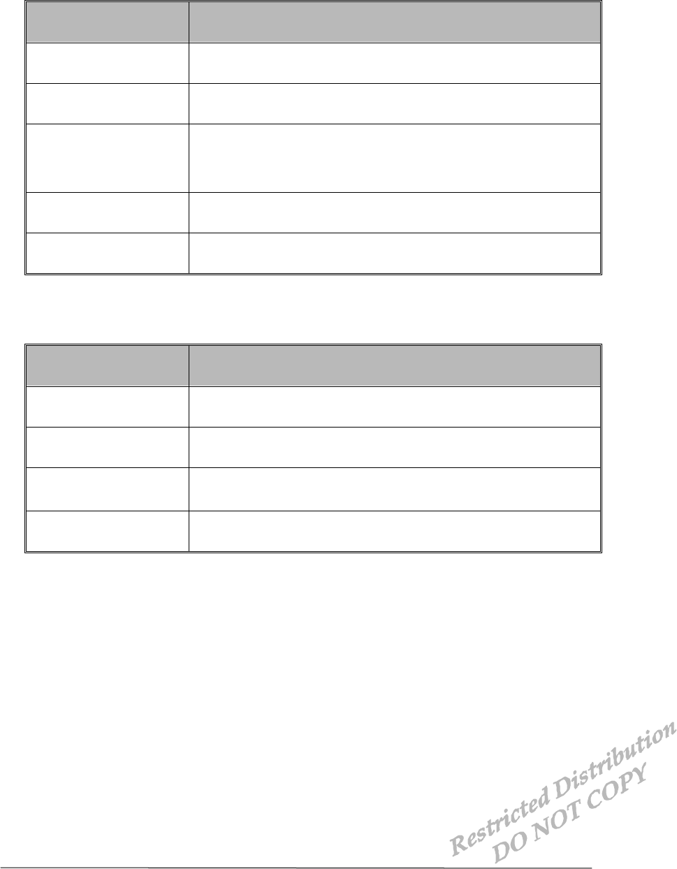
1.2.1 General Specifications
PARAMETERS DESCRIPTIONS
External Access Code-Division-Multiple-Access (CDMA)
CDMA Protocol IS-95 A/B, IS-98A, IS-126, IS-637A, IS-707A
Data Rate 64Kbps
Transmit/Receive
Frequency Interval 45MHz
Band Width 1.23MHz
Operating Voltage DC 6V ± 10%
Current Consumption Stand by mode : Idle (140mA) , Busy mode : 900mA (Max)
Operating Temperature -30 ~ +60
Frequency Stability ±300Hz
Antenna Whip Antenna, 50ohm
Size 102 X 80 X 36mm with case
Weight About 180g
External Interface RS-232, Digital/Analog Audio, LCD, Keypad, Ringer
External On/Off Control
01-DT800-1 X1 AnyDATA.NET Proprietary – Use Subject to
Restrictions 3
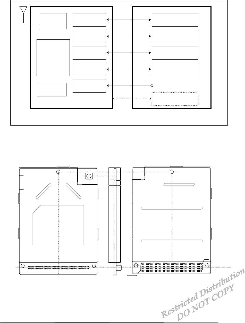
1.2.2 Receive Specifications
PARAMETERS DESCRIPTIONS
Frequency Range 869.04 ~ 893.97 MHz
Sensitivity Below –104 dBm
Interference
Rejection
Single tone (-30dBm @900KHz) : Below –101dBm
Two tone (-43 dBm @900KHz and 1700KHz) : Below –101dBm
Two tone (-32 dBm @900KHz and 1700KHz) : Below –90dBm
Two tone (-21 dBm @900KHz and 1700KHz) : Below –79dBm
Spurious Wave
Suppression Below –80dBc
Input Dynamic Range -25 dBm ~ -104dBm
1.2.3 Transmit Specifications
PARAMETERS DESCRIPTIONS
Frequency Range 824.04 ~ 848.97 MHz
Nominal Power 0.32 W
Minimum Controlled
Output Power Below –50dBm
Max Power Spurious 900KHz : Below –42dBc/30KHz
1.98MHz : Below –54dBc/30KHz
1.2.4 Standards
IS-95 A/B : Protocol Between MS & BTS
IS-96A : Voice Signal Coding
IS-98A : Base MS Function
IS-126 : Voice Loop-Back
IS-637 : Short Message Service
IS-707 : Data Service
01-DT800-1 X1 AnyDATA.NET Proprietary – Use Subject to
Restrictions 4
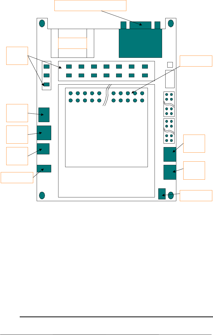
1.3 Interface Diagram
• Interface Block Diagram
1.4 General Features
60
1
Top ViewSide ViewBottom View
RF Unit
MSM3000
JTA G
UART
GPIO
U ser
Interface
CODEC
LD O
R S-232
U ser D efine
LC D , Keypad
Ringer
MIC/EAR
E x te rn a l CODEC
ANT
D TS-800
E x te rn a l Power
4.2V
Application Device
01-DT800-1 X1 AnyDATA.NET Proprietary – Use Subject to
Restrictions 5
UART 2
9pin connector (UART 1)
60 pin connector
Ear_Jack
for DTSS
Ear_Jack
for DTS
3 pin connector
DTS
DTSS
DC Jack
(small)
Ant_cable
DC Jack
(large)
On/Off
Switch
LED
GPIODATAKEYSENSE
AUX_PCM
• General Features
2 PIN Description
01-DT800-1 X1 AnyDATA.NET Proprietary – Use Subject to
Restrictions 6
2.1 I/O Description Parameters
SYMBOL DESCRIPTIONS
ICOMS Input
OOutput
BBi-directional
N Voltage or Current Level
IS Input with Schmitt Trigger
BS Bi-directional Schmitt Trigger
PU Internal Pull-Up
PD Internal Pull-Down
2.2 PIN Names and Pinouts
2.2.1 60-Pin Connector
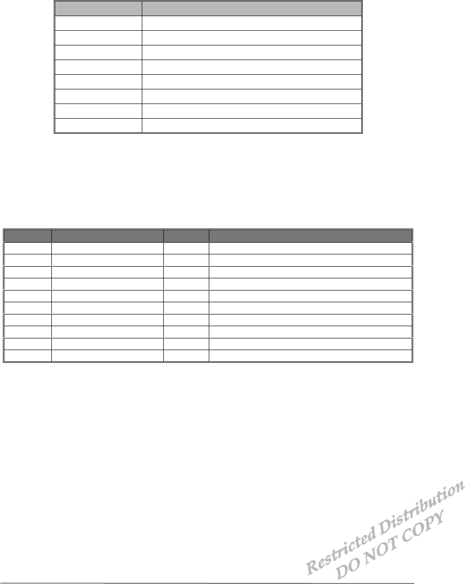
PIN NAME TYPE DESCRIPTION
1 DP_DCD/ O Data carrier detect
2 DP_RI/ O Ring indicator
3 DP_RTS/ O Request to send
4 DP_TXD O Transmit data
5 DP_DTR/ I Data terminal ready
6 DP_RXD IS Receive data
7 DP_CTS/ IS Clear to send
8 GND Signal ground
9 AUX_PCM_DIN IS External CODEC PCM data input
10 GND Signal ground

PIN Descriptions DTS-800 Reference Manual Application Information
01-DT800-1 X1 AnyDATA.NET Proprietary – Use Subject to
Restrictions 7
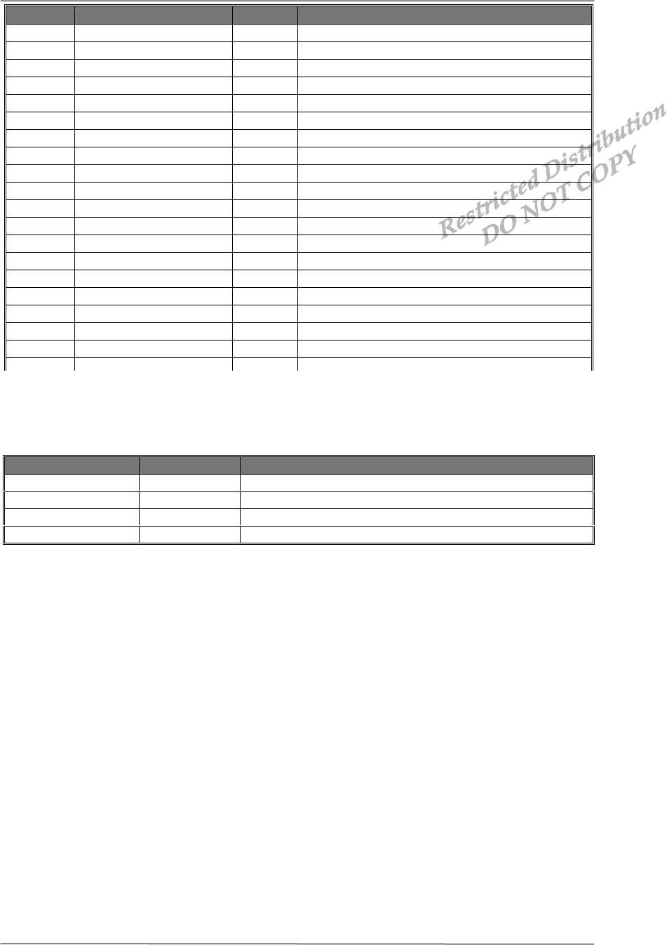
PIN NAME TYPE DESCRIPTION
11 AUX_PCM_DOUT O External CODEC PCM data output
12 GPIO_INT0 BS_PU General purpose in/output by interrupt
13 AUX_PCM_CLK O External CODEC PCM clock
14 AUX_PCM_SYNC O External CODEC PCM sync.
15 GPIO00(SMS)_(GREEN
)BS_PU General purpose input output
16 GPIO01(IDLE)_(RED) BS_PU General purpose input output
17 GPIO02 BS_PU General purpose input output
18 GPIO03 BS_PU General purpose input output
19 GPIO04 BS_PU General purpose input output
20 GPIO05 BS_PU General purpose input output
21 GPIO13 BS_PD General purpose input output
22 GPIO14 BS_PD General purpose input output
23 RINGER O Ringer output
24 D00 B Data line
25 D01 B Data line
26 D02 B Data line
27 D03 B Data line
28 D04 B Data line
29 D05 B Data line
30 D06 B Data line
31 D07 B Data line
32 A01 B Address line
33 RES_OUT/ O Reset output
34 LCD_CS/ O LCD chip select
35 RD/ BS Read enable output
36 LWR/ BS_PU Write enable output
37 GND Signal ground
38 GND Signal ground
39 VEXT_DC I External power input
40 VEXT DC I External power input
PIN Descriptions DTS-800 Reference Manual Application Information
01-DT800-1 X1 AnyDATA.NET Proprietary – Use Subject to
Restrictions 8
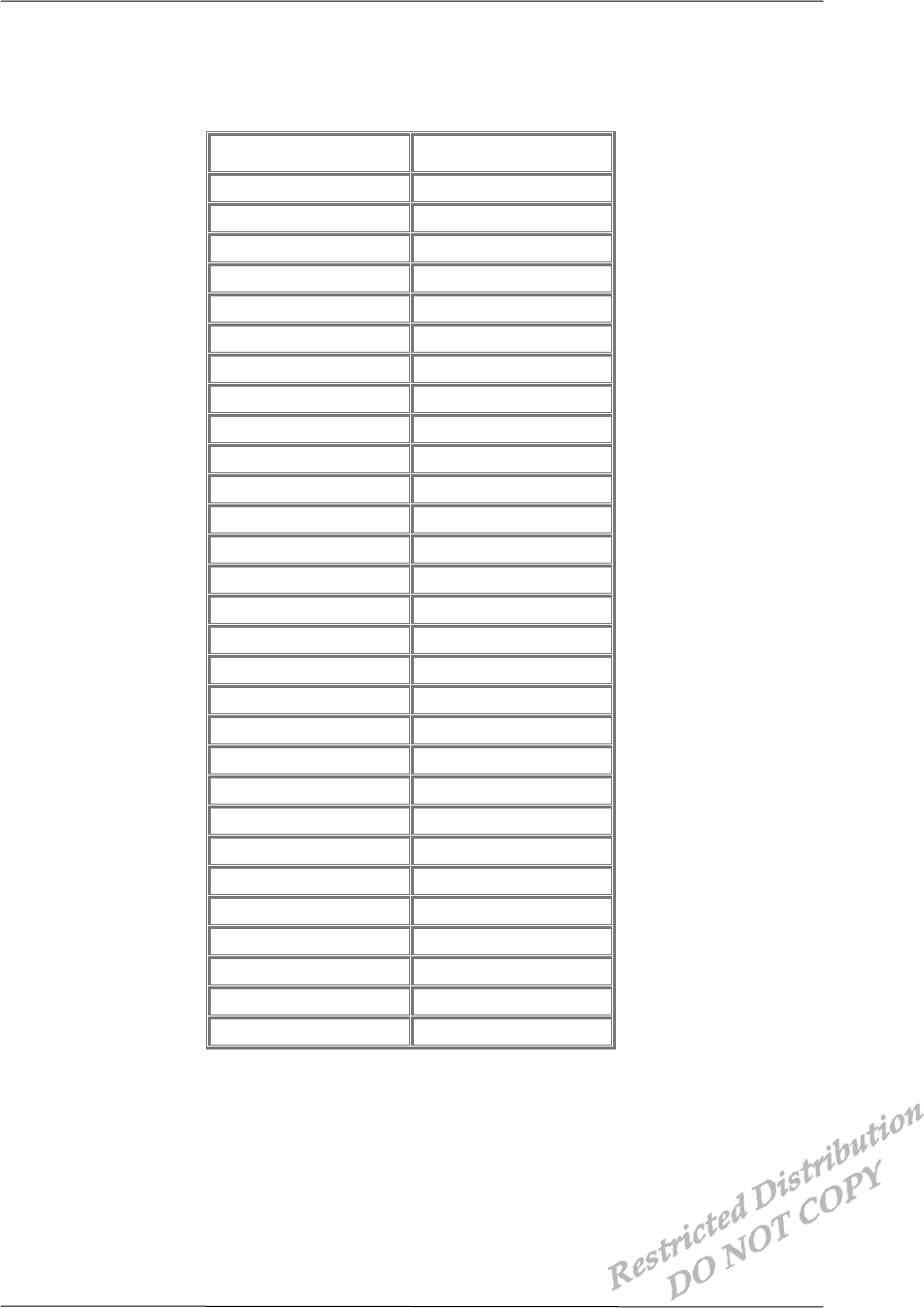
2.2.2 Analog Audio Signals
NAME TYPE DESCRIPTION
MIC+ I Microphone audio input
MIC- IS Ear/microphone set detect
EAR O Ear audio output
GND_A Audio ground
PIN NAME TYPE DESCRIPTION
41 GPIO30 BS General purpose input output
42 GPIO29 BS General purpose input output
43 GPIO22 BS_PD General purpose input output
44 GPIO21 BS_PD General purpose input output
45 GPIO20 BS_PD General purpose input output
46 GPIO19 BS_PD General purpose input output
47 GPIO18 BS_PD General purpose input output
48 GPIO_INT3 BS_PU General purpose in/output by interrupt
49 GPIO_INT1 BS_PU General purpose in/output by interrupt
50 KEYSENSE0/ IS_PU Key sense input
51 KEYSENSE1/ IS_PU Key sense input
52 KEYSENSE2/ IS_PU Key sense input
53 KEYSENSE3/ IS_PU Key sense input
54 KEYSENSE4/ IS_PU Key sense input
55 LCD_E O LCD read enable
56 A00 B Address line
57 A02 B Address line
58 A03 B Address line
59 GND Signal ground
60 VEXT DC I External power input
PIN Description DTS-800 Reference Manual Application Information
01-DT800-1 X1 AnyDATA.NET Proprietary – Use Subject to
Restrictions 9
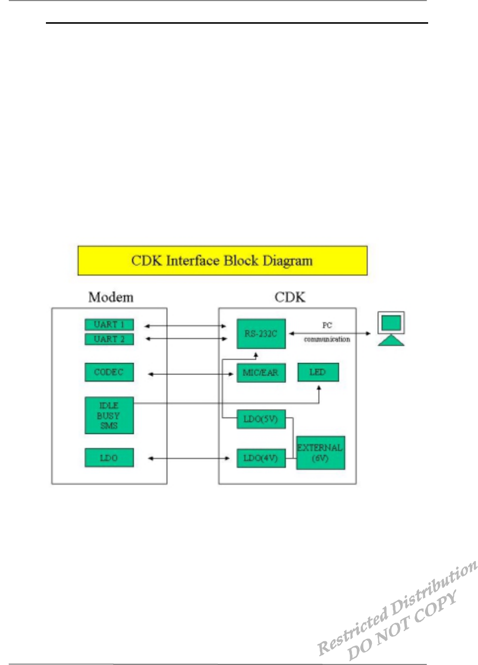
2.3 60-PIN Connector Pinouts (Top view)
• 60-PIN Connector
Pinouts
1 DP_DCD/ 2 DP_RI/
3 DP_RTS/ 4 DP_TXD
5 DP_DTR/ 6 DP_RXD
7 DP_CTS/ 8 GND
9 AUX_PCM_DIN 10 GND
11 AUX_PCM_DOUT 12 GPIO_INT0
13 AUX_PCM_CLK 14 AUX_PCM_SYNC
15 GPIO00 16 GPIO01
17 GPIO02 18 GPIO03
19 GPIO04 20 GPIO05
21 GPIO13 22 GPIO14
23 RINGER 24 D00
25 D01 26 D02
27 D03 28 D04
29 D05 30 D06
31 D07 32 A01
33 RES_OUT/ 34 LCD_CS/
35 RD/ 36 LWR/
37 GND 38 GND
39 VEXT_DC 40 VEXT_DC
41 GPIO30 42 GPIO29
43 GPIO22 44 GPIO21
45 GPIO20 46 GPIO19
47 GPIO18 48 GPIO_INT3
49 GPIO_INT1 50 KEYSENSE0/
51 KEYSENSE1/ 52 KEYSENSE2/
53 KEYSENSE3/ 54 KEYSENSE4/
55 LCD-E 56 A00
57 A02 58 A03
59 GND 60 VEXT_DC
Interface Description DTS-800 Reference Manual Application Information
01-DTS800 CDK-1 X1 AnyDATA.NET Proprietary – Use Subject to
Restrictions 10
3 Interface Descriptions
3.1 Overview
This chapter covers information needed to design the DTS-800 CDK into a subscriber unit
application. In addition, this chapter describes some of internal blocks of the device necessary
for complete understanding of the various interfaces.
This chapter discusses the interface to the major blocks of the DTS-800 CDK as shown in
below
Figures. These blocks include :
CODEC Interface
UART Interface
General Purpose Interface
User Interface
JTAG Interface
• Interface Block Diagram
3.2 CODEC Interface
Interface Description DTS-800 Reference Manual Application Information
01-DTS800 CDK-1 X1 AnyDATA.NET Proprietary – Use Subject to
Restrictions 11
The CODEC Interface configured by internal and external figures.
If use internal CODEC Interface, additional glue logic is not necessary. The modem provides
very simple audio interface.
Otherwise, An external CODEC is necessary support for car-kit system. The modem provides
PCM CODEC Interface.
3.2.1 Internal CODEC Interface
The modem contains analog audio interface circuitry. Contained audio interface
supports all of required conversation and amplification stages for the audio front end.
The audio interface includes the amplification stages for both the microphone and
earphone. The interface supports one differential microphone input and one differential
earphone output.
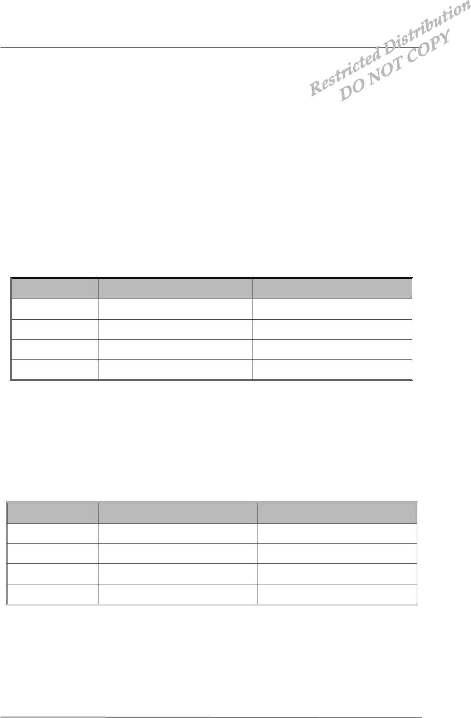
NAME DESCRIPTION CHARACTERISTIC
MIC + MIC Input Analog Input
MIC - EAR/MIC Set Detect Logic Input
EAR Earphone Output Analog Output
GND_A Audio Ground
• Analog Audio Pinouts
3.2.2 External CODEC Interface
The PCM CODEC interface used to car-kit audio system. This interface is optional item.
External CODEC interface signals are below :
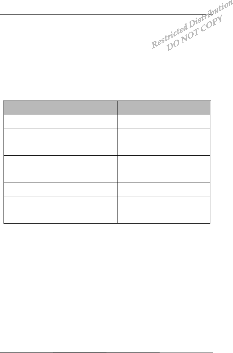
NAME DESCRIPTION PINOUTS
AUX_PCM_CLK PCM Clock 13’th of 60-Pin Connector
AUX_PCM_DIN PCM Data Input 9’th of 60-Pin Connector
AUX_PCM_DOUT PCM Data Output 11’th of 60-Pin Connector
AUX_PCM_SYNC PCM Sync. 14’th of 60-Pin Connector
• Digital CODEC Pinouts
3.3 UART Interface
Interface Description DTS-800 Reference Manual Application Information
01-DTS800 CDK-1 X1 AnyDATA.NET Proprietary – Use Subject to
Restrictions 12
The Universal Asynchronous Receiver Transmitter (UART) communicates with serial data
that conforms the RS-232 Interface protocol. The modem provides 3.0V CMOS level outputs
and 3.0V CMOS switching input level. And all inputs have 5.0V tolerance but 3.0V or 3.3V
CMOS logic compatible signals are highly recommended.
All the control signals of the RS-232 signals are active low, but data signals of RXD, and TXD
Are active high.
The UART has a 64byte transmit (TX) FIFO and a 64byte receive (RX) FIFO. The UART
Features hardware handshaking, programmable data sizes, programmable stop bits, and odd,
even, no parity. The UART operates at a 115.2kbps maximum bit rate.
NAME DESCRIPTION CHARACTERISTIC
DP_DCD/ Data Carrier Detect Network connected from the modem
DP_RI/ Ring Indicator Output to host indicating coming call
DP_RTS/ Request to Send Ready for receive from host
DP_TXD Transmit Data Output data from the modem
DP_DTR/ Data Terminal Ready Host ready signal
DP_RXD Receive Data Input data to the modem
DP_CTS/ Clear to Send Modem output signal
GND Signal Ground Signal ground
• UART Interface Pinouts
3.4 General Purpose Interface

Interface Description DTS-800 Reference Manual Application Information
01-DTS800 CDK-1 X1 AnyDATA.NET Proprietary – Use Subject to
Restrictions 13
The general purpose interface consist of 18 user-definable bi-directional, 3 user-definable
interrupt input pins.
Each GPIO pin can be configured as input interrupt source. Also some GPIO pins can be
used to output control pin from the modem. The user can define these pins properly
NAME TYPE CHARACTERISTIC
GPIO00 BS_PU Configured as a pull-up, Bi-directional
GPIO01 BS_PU Configured as a pull-up, Bi-directional
GPIO02 BS_PU Configured as a pull-up, Bi-directional
GPIO03 BS_PU Configured as a pull-up, Bi-directional
GPIO04 BS_PU Configured as a pull-up, Bi-directional
GPIO05 BS_PU Configured as a pull-up, Bi-directional
GPIO13 BS_PD Configured as a pull-down, Bi-directional
GPIO14 BS_PD Configured as a pull-down, Bi-directional
GPIO18 BS_PD Configured as a pull-down, Bi-directional
GPIO19 BS_PD Configured as a pull-down, Bi-directional
GPIO20 BS_PD Configured as a pull-down, Bi-directional
GPIO21 BS_PD Configured as a pull-down, Bi-directional
GPIO22 BS_PD Configured as a pull-down, Bi-directional
GPIO29 BS Bi-directional
GPIO30 BS Bi-directional
GPIO_INT0 BS_PU Configured as a pull-up, Bi-directional
GPIO_INT1 BS_PU Configured as a pull-up, Bi-directional
GPIO_INT3 BS_PD Configured as a pull-down, Bi-directional
• General Purpose Interface Pinouts
3.5 User Interface
Interface Description DTS-800 Reference Manual Application Information
01-DTS800 CDK-1 X1 AnyDATA.NET Proprietary – Use Subject to
Restrictions 14
3.5.1 Key Pad
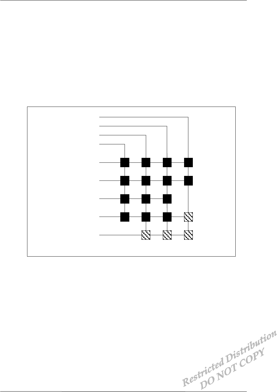
The key pad interface is consists of 4X5 matrix pattern. 5-KEYSENSE/[4:0] pins can be
used to connect a matrix key pad to the modem. But all pins are not necessary, just
4-KEYSENSE/ pins are used. KEYSENSE/ pins are active low.
5-GPIO pins are necessary to make other side of matrix, 5-GPIO pins are must active
high. The general key pad matrix are below :
• Keypad Matrix
3.5.2 LCD
The modem supports CLD interface. The LCD interface composed of 15-signals.
#
KEYSENSE0/
KEYSENSE1/
KEYSENSE2/
KEYSENSE3/
1
-
GPIO
2
-
GPIO
3
-
GPIO
4
-
GPIO
5
-
GPIO
9
6
3
0
8
5
2
*
7
4
1
SEND
END
Reserved
Interface Description DTS-800 Reference Manual Application Information
01-DTS800 CDK-1 X1 AnyDATA.NET Proprietary – Use Subject to
Restrictions 15
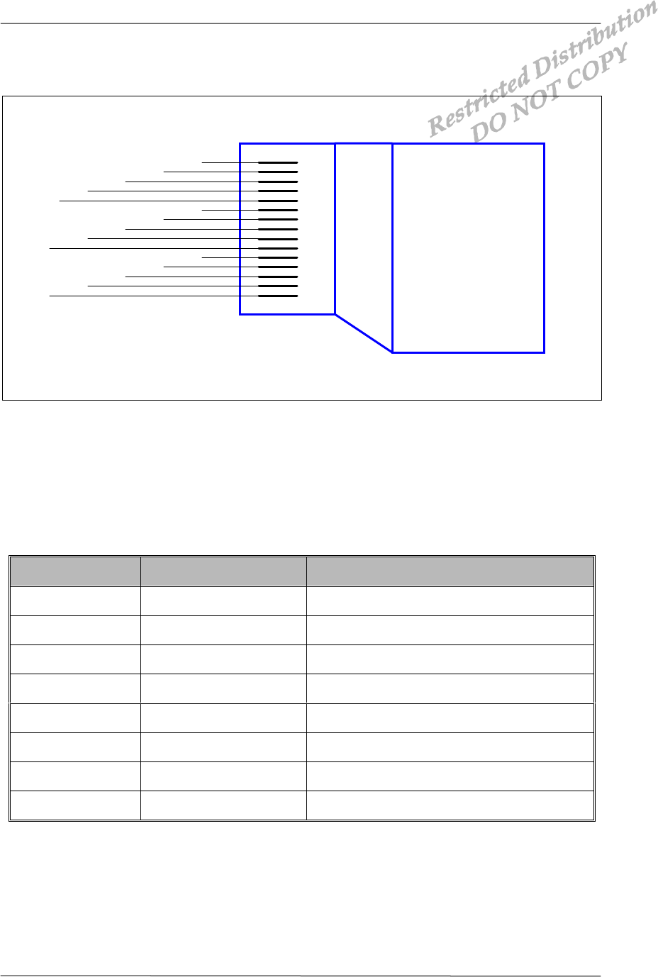
Direct access to LCD driver is not applicable, 8-bit operation interface logic is needed.
LCD interface block diagram is below :
• LCD Interface Block Diagram
NAME TYPE DESCRIPTION
LWR/ BS_PU LCD RW pin out from the modem
RD/ BS LCD E pin out from the modem
A01 B LCD RS pin out from the modem
LCD_CS/ O LCD Chip Select pin out from the modem
RES_OUT/ O LCD Reset from the modem
D00 ~ D07 O LCD Data Lines from the modem
VDD LCD Power Supply
GND LCD Signal Ground
• LCD Interface Signals
3.5.3 Ringer
GND
LW R /
RD/
A01
LCD_CS/
RES_OUT/
D00
D01
D02
D03
D04
D05
D06
D07
VD D
GND
RW
E
RS
CS
RESET
DO
D1
D2
D3
D4
D5
D6
D7
VD D
LC D
8-Bit
O peration
Interface
Lo gic

Interface Description DTS-800 Reference Manual Application Information
01-DTS800 CDK-1 X1 AnyDATA.NET Proprietary – Use Subject to
Restrictions 16
The Ringer provides Ringer output to drive the sound transducer on the host. It alarms
the voice call events and key tone if key pad is connected.

01-DTS800 CDK-1 X1 AnyDATA.NET Proprietary – Use Subject to
Restrictions 17
4 Electrical Specifications
4.1 DC Electrical Specifications
4.1.1 Absolute Maximum Ratings
Operating the modem under conditions that exceed those listed in the Absolute Maximum
Ratings table may result in damage to the modem.
Absolute Maximum Ratings are limiting values, and are considered individually. While
All other parameters are within their specified operating ranges. Functional operation of
the modem under any of the conditions in the Absolute Maximum Ratings table is not
implied.
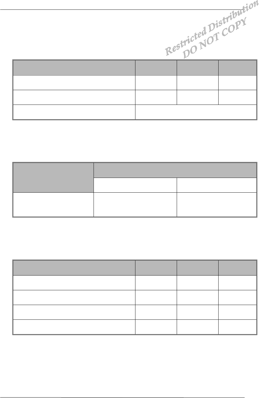
PARAMETER MIN MAX UNITS
Storage Temperature -40 +80
Voltage On Any Input or Output Pin -0.5 +3.7 V
Supply Voltage +7.0 V
Initializing Current 100 mA
Drop No damages after 60-Inch drop over
concrete floor
• Absolute Maximum Ratings
Electrical Specifications DTS-800 Reference Manual Application Information
01-DTS800 CDK-1 X1 AnyDATA.NET Proprietary – Use Subject to
Restrictions 18
4.1.2 Recommended Operating Conditions
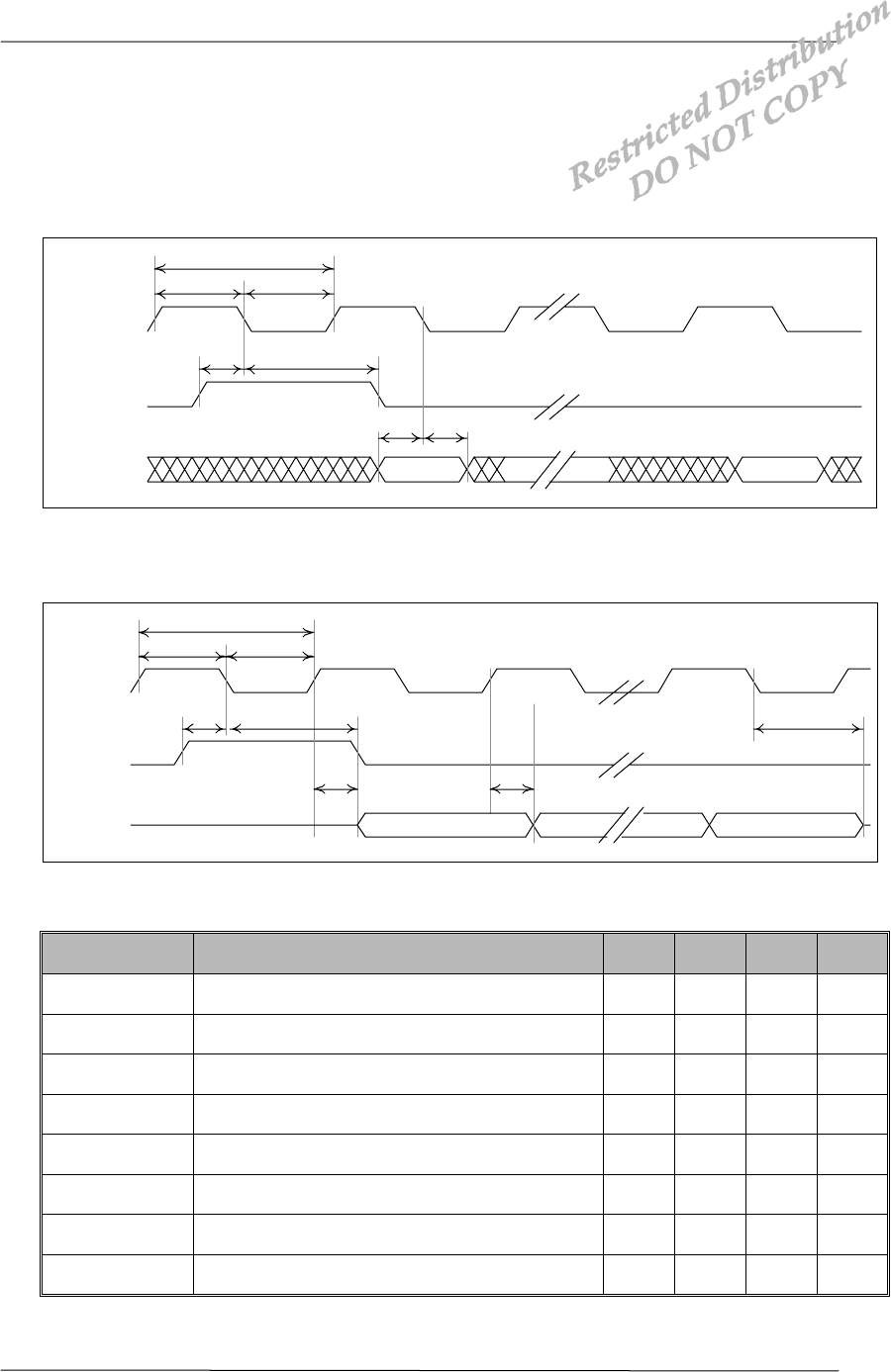
PARAMETER MIN MAX UNITS
Supply Voltage +5.0 +7.0 V
Operating Temperature -30 +60
Operating Humidity 95%(50 ) Relative Humidity
4.1.3 Power Consumption
STANDBY
CONVERSATION
(Busy) Idle Sleep
900mA (MAX) 130mA 20mA
4.1.4 Serial Interface Electrical Specifications
PARAMETER MIN MAX UNITS
Input High Voltage +2.0 +3.7 V
Input Low Voltage -0.5 +0.8 V
Output High Voltage +2.4 V
Output Low Voltage +0.4 V
Electrical Specifications DTS-800 Reference Manual Application Information
01-DTS800 CDK-1 X1 AnyDATA.NET Proprietary – Use Subject to
Restrictions 19
4.2 Timing characteristics
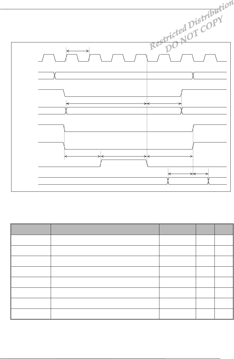
4.2.1 External CODEC Timing
• External PCM CODEC to Modem timing
• Modem to External PCM CODEC timing
PARAMETER DESCRIPTION MIN TYP. MAX UNIT
tclk PCM-CLK cycle time 400 500 ns
tclkl PCM-CLK low time 200 250 ns
tclkh PCM-CLK high time 200 250 ns
tsu(sync) PCM_SYNC setup time to PCM_CLK falling 150 ns
th(sync) PCM_SYNC hold time after PCM_CLK falling 350 ns
tsu(din) PCM_DIN setup time to PCM_CLK falling 50 ns
th(din) PCM_DIN hold time after PCM_CLK falling 10 ns
tpdout Delay from PCM_CLK falling to PCM_DOUT 50 ns
• External PCM CODEC Parameters
t
clk
t
clkl
t
clkh
t
su(sync)
t
h(sync)
t
su(din)
t
h(din)
MSB LS B
PCM _CLK
PCM _SYNC
PCM _DIN
t
clk
t
clkl
t
clkh
t
su(sync)
t
h(sync)
MSB LSB
PC M _C LK
PC M _SYN C
PCM_DOUT
t
pdout
t
pdout
t
zdout
Electrical Specifications DTS-800 Reference Manual Application Information
01-DTS800 CDK-1 X1 AnyDATA.NET Proprietary – Use Subject to
Restrictions 20
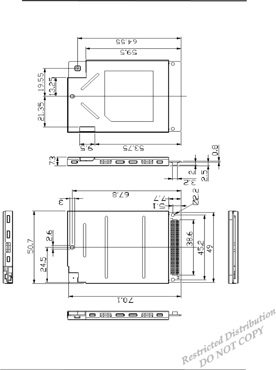
4.2.2 LCD Timing
• LCD Timing
PARAMETER DESCRIPTION MIN MAX UNIT
tLCDES LCD_CS/ active to LCD_E active ns
tLCDEHI Pulse width if LCD_E active ns
tLCDEH LCD_E inactive to LCD_CS/ inactive (write) ns
tLCDEHR LCD_E inactive to LCD_CS/ inactive (Read)
tRDS Read data setup ns
tRDH Read data hold ns
tWRS Write data setup to LCD_E inactive ns
tWRH Write data hold from LCD_E inactive ns
• LCD Timing Parameters
; κ, Ι, ν ισ ιντεγερ λοωερ τηαν 16, ΜΧΛΚ ισ ιντερναλ Χλοχκ οφ µοδεµ
t
WRS
MCLK
(m odem )
A[21:0]
LW R /
Write
D ata[7:0]
LCD_CS/
RD/
LCD_E
R ead
D ata[7:0]
T
t
WRH
t
LCDES
t
LCDEHI
t
LCDEH
t
RDS
t
RDH
LCD Data W rite
LCD Data Read
01-DTS800 CDK-1 X1 AnyDATA.NET Proprietary – Use Subject to
Restrictions 21
5 Mechanical Dimensions
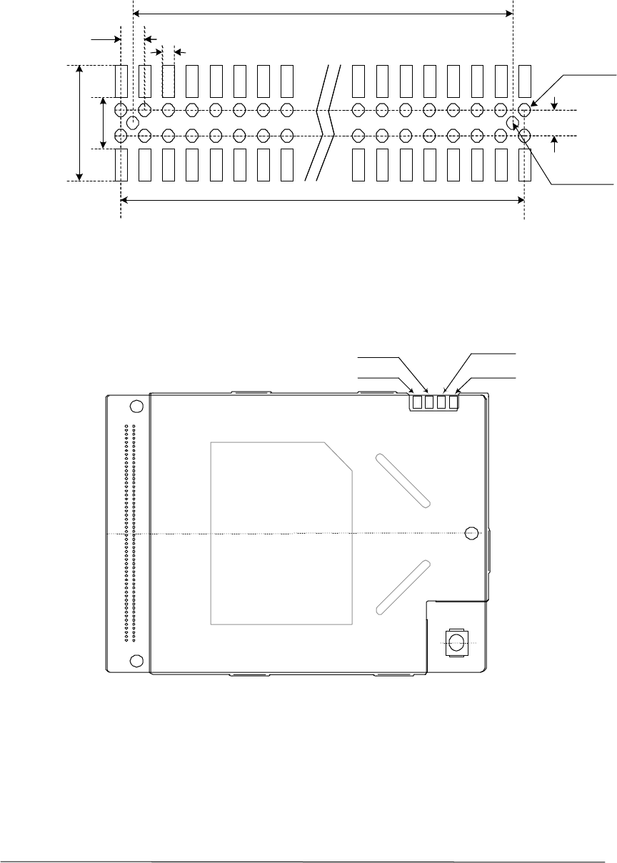
5.1 DTS-800 CDK Outline
01-DTS800 CDK-1 X1 AnyDATA.NET Proprietary – Use Subject to
Restrictions 22
5.2 60-Pin Connector Mechanical Dimension
5.3 Analog Audio Pin-Out
6. FCC Notice
40
1.27
0.5
5
φ
0.70 0.10
1.2
7
5.40
2.20
φ
0.70 0.05
((P in num ber/2)-2)x1.27
±
±
((P in num ber/2)-1)x1.27
MIC-
MIC+
GND
EAR
4 3 2 1

01-DTS800 CDK-1 X1 AnyDATA.NET Proprietary – Use Subject to
Restrictions 23
This equipment has been tested and found to comply with the limits for a Class B digital device,
pursuant to part 15 of the FCC Rules. These limits are designed to provide reasonable protection
against harmful interference in a residential installation. This equipment generates, uses and can
radiate radio frequency energy and, if not installed and used in accordance with the instructions,
may cause harmful interference to radio communications. However, there is no guarantee that
interference will not occur in a particular installation. If this equipment does cause harmful
interference to radio or television reception, which can be determined by turning the equipment
off and on, the user is encouraged to try to correct the interference by one or more of the
following measures:
! Ρεοριεντ ορ ρελοχατε τηε ρεχειϖινγ αντεννα.
! Ινχρεασε τηε σεπαρατιον βετωεεν τηε εθυιπµεντ ανδ ρεχειϖερ.
! Χοννεχτ τηε εθυιπµεντ ιντο αν ουτλετ ον α χιρχυιτ διφφερεντ φροµ τηατ το ωηιχη
τηε ρεχειϖερ ισ χοννεχτεδ.
! Χονσυλτ τηε δεαλερ ορ αν εξπεριενχεδ ραδιο/Τς τεχηνιχιαν φορ ηελπ.