AnyDATA EMIVV2 CDMA DATA MODEM User Manual
AnyDATA Corporation CDMA DATA MODEM Users Manual
AnyDATA >
Contents
- 1. Users Manual
- 2. Users Manual 2
Users Manual

EMIV-DUAL V2.0 User Manual
Application Information
Sep. 29, 2006
01-EMIV-DUAL V2.0_X1
AnyDATA.NET
AnyTime AnyPlace Any Wireless Data Solutions™
EMIV-DUAL V2.0 AnyDATA.NET Proprietary – Use Subject to Restrictions

AnyDATA CDMA EMIV-DUAL V2.0
Copyright © 2005 AnyDATA Corp. All Rights Reserved.
Any part of this document may not be distributed, communicated, reproduced or
transmitted in any form or by any means, electronic or mechanical or otherwise, for any
purpose, without the permission of AnyDATA Corp.
AnyDATA Inc. does not assume any liability arising out of the application or use of its
products. AnyDATA Inc. assumes no responsibility for any damage or loss resulting
from the misuse of its products. AnyDATA Inc. assumes no responsibility for any loss
or claims by third parties, which may arise through the use of its products. AnyDATA
Inc. assumes no responsibility for any damage or loss caused by the deletion or loss of
data as a result of malfunctions or repairs
This document can be subject to revision without further notice.
Contact Address
Headquarter
AnyData Corporation
18902 Bardeen Ave, lrvine,
CA 92612-1522 U.S.A.
http://www.anydata.com
e-mail: info@uct.net
Rep:1-949-833-0011
Fax: 1-949-833-0022
AnyData(China)
489 Song Tao Road, Sector B,
1 st Fl. Pudong ZhanJiang Hi-
Tech Park, Shanghai, 201203,
P.R.China
http://www.anydata.net.cn
e-mail: info@anydata.net.cn
Rep:+86-21-5080-4828
Fax:+86-21-5080-3828
AnyData.Net Inc.(Korea)
DaeGo Bldg, 8 th., 1591-10
Kwanyang-dong, Dongan_gu,
Anyang City, Kyunggi-do Korea.
http://www.anydata.co.kr
e-mail: infodata@anydata.net
Rep:+82-31-380-7100
Fax:+82-31-476-6021
!
Warning: Exposure to Radio Frequency Radiation
The radiated output power of this device is below the FCC radio frequency
exposure limits. Nevertheless, the device should be used in such a manner
that the potential for human contact during normal operation is minimized. In
order to avoid the possibility of exceeding the FCC radio frequency exposure
limits, human proximity to the antenna should not be less than 20cm during
normal operation and the gain of the external antenna must not exceed 1dBi.
This device contains DTG2000-DUAL V2.0 of which the FCC ID is P4M-
DTG2000V2 and the IC number is 4594A-DTG2KV2.
EMIV-DUAL V2.0 AnyDATA.NET Proprietary – Use Subject to Restrictions

Interface Description EMIV-DUAL V2.0 Reference Manual Application Information
Contents
1 Introduction
1.1 Purpose
1.2 Organization
1.3 Revision History
2 Overview
2.1 Application Description
2.2 Technical Specifications
2.2.1 General Specification
2.2.2 Receive Specification
2.2.3 Transmit Specification
2.2.4 Standards
2.3 Interface Diagram
2.4 EMIV-DUAL V2.0 Photo
2.5 Internal Module Photo
3 PIN Description
3.1 8-Pin Connector (RS232 Standard)
3.2 3-Pin Connector (Debugging)
3.3 DC Power Connector
EMIV-DUAL V2.0 AnyDATA.NET Proprietary – Use Subject to Restrictions

Interface Description EMIV-DUAL V2.0 Reference Manual Application Information
4 Interface Descriptions
4.1 Overview
4.2 RS232 Interface (Standard)
5 Electrical Specifications
5.1 Absolute Maximum Ratings
5.2 Recommended Operating Conditions
5.3 Power Consumption
5.4 Serial Interface Electrical Specifications
6 Mechanical Dimension
6.1 EMIV-DUAL V2.0 Outline
7 Installation Example
EMIV-DUAL V2.0 AnyDATA.NET Proprietary – Use Subject to Restrictions
Interface Description EMIV-DUAL V2.0 Reference Manual Application Information
1. Introduction
1.1 Purpose
This Manual provides hardware interface and programming information for EMIV-DUAL V2.0
CDMA Wireless Data Modem.
1.2 Organization
The interface and operation section is organized into the following subsections:
Section 2 – Introduces users to the EMIV-DUAL V2.0 CDMA Wireless Data Modem basic
features and general specifications.
Section 3 – Contains EMIV-DUAL V2.0 Pin description - DC12V Input Port, 8pin Serial Port
and Debugging Port.
Section 4 – Describes the UART Interface.
Section 5 – Specifies the recommended operating conditions, DC voltage characteristics, I/O
timing, and power estimations for the modem.
Section 6 – Provides package dimensions and outlook features for the modem.
Section 7 – Displays installation example.
1.3 Revision History
The revision history for this document is shown in Table 1-1.
Table 1-1 Revision History
Version Date Description
X1 Sep 2006 Initial Release
EMIV-DUAL V2.0 AnyDATA.NET Proprietary – Use Subject to Restrictions

Interface Description EMIV-DUAL V2.0 Reference Manual Application Information
2. Overview
2.1 Application Descriptions
The CDMA Wireless Data Modem is a complex consumer communications instrument that relies
heavily on both digital signal and embedded processor technologies. The Wireless Data Modem
manufactured by AnyDATA.NET supports Code-Division-Multiple-Access (CDMA). This operates in
800MHz CDMA and 1900MHz PCS spectrum.
In a continuing effort to simplify the design and to reduce the production cost of the Wireless Data
Modem, AnyDATA.NET has successfully developed the EMIV-DUAL V2.0. The EMIV-DUAL V2.0 is
AnyDATA.NET’s latest compact Wireless Data Modem operating in 800MHz CDMA and 1900MHz
PCS spectrum, also contains complete digital modulation and demodulation system for CDMA standards
as specified in IS-95 A/B and IS-2000.
The subsystem within the EMIV-DUAL V2.0 includes a CDMA processor (MSM6050), an
integrated CODEC with an ear piece and microphone amplifiers, and an RS-232 serial interface
supporting forward link data communications of a rate of 153kbps.
The EMIV-DUAL V2.0 provides external interface. External interface includes the standard RS-232,
Digital Audio, External reset control, parallel LCD Display, Keypad, Ringer extension ports and R-UIM
for China market.
The EMIII-DUAL has the capability to power down unused circuits in order to dynamically
minimize power consumption.
EMIV-DUAL V2.0 AnyDATA.NET Proprietary – Use Subject to Restrictions

Interface Description EMIV-DUAL V2.0 Reference Manual Application Information
2.2 Technical Specifications
2.2.1 General Specifications
Parameters Descriptions
External Access Code-Division-Multiple-Access (CDMA)
CDMA Protocol IS-95 A/B, IS-126, IS-637A, IS-707A, IS-2000
Data Rate 153 Kbps max. on both the forward and reverse links
Transmit/Receive
Frequency Interval 45MHz for Cellular and 80MHz for PCS
Band Width 1.23MHz
RF technology Zero Intermediate Frequency
Number of Channel 832 for Cellular and 42 for PCS
Operating Voltage DC 7V ~ 16V
Current Consumption Sleep mode : 30mA, Idle mode (70mA) ,
Traffic mode : 350mA (Max) at 12V
Operating Temperature -30℃ ~ +60℃
Frequency Stability ±300Hz for 800MHz CDMA and ±150Hz for 1900MHz CDMA
Antenna Magnet mount helical antenna, 50ohm,
1dBi Gain for 800MHz and 1900MHz
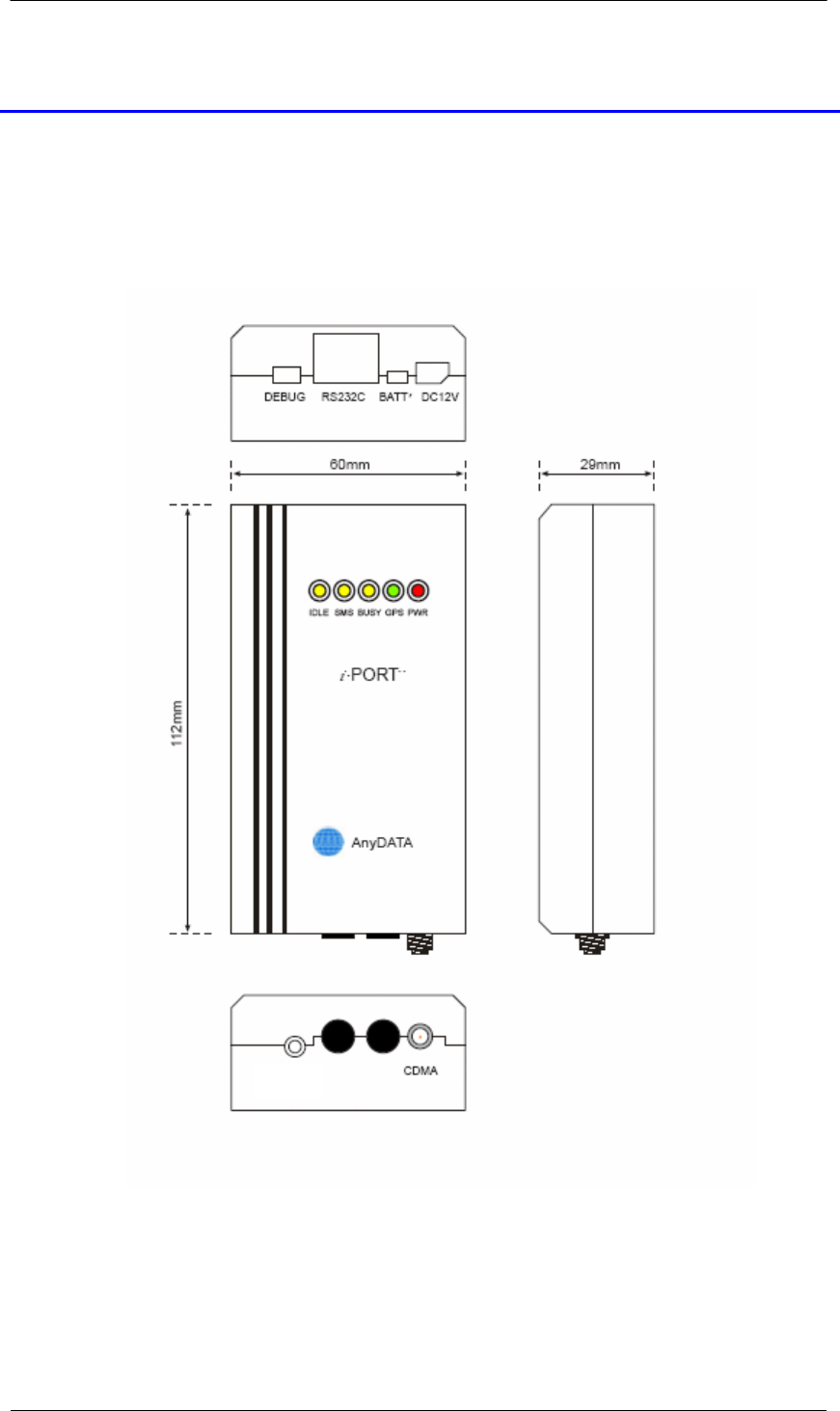
Size 60 X 112 X 29mm
Weight About 110g
External Interface RS-232 (Molex-8pin 85503), Power (12VDC Molex-2pin 5268), Dual
Antenna (800MHz,1900MHz), Debug port (Mini USB)
EMIV-DUAL V2.0 AnyDATA.NET Proprietary – Use Subject to Restrictions

Interface Description EMIV-DUAL V2.0 Reference Manual Application Information
2.2.2 Receive Specifications
Parameters Descriptions
Frequency Range 869.04 ~ 893.97 MHz for 800MHz CDMA and
1931.25 ~ 1988.75MHz for 1900MHz CDMA
Sensitivity Below –104dBm
800MHz
Interference
Rejection
1900MHz
Single tone (-30dBm @900KHz): Below –101dBm
Two tone (-43 dBm @900KHz and 1700KHz): Below –101dBm
Two tone (-32 dBm @900KHz and 1700KHz): Below –90dBm
Two tone (-21 dBm @900KHz and 1700KHz): Below –79dBm
Single tone (-30dBm @1250KHz): Below –101dBm
Two tone (-43 dBm @1250KHz and 2050KHz): Below –101dBm
Spurious Wave
Suppression Below –80dBc
Input Dynamic Range -25dBm ~ -104dBm
2.2.3 Transmit Specifications
Parameters Descriptions
Frequency Range
Cellular
PCS
824.04 ~ 848.97 MHz
1851.25 ~ 1908.75MHz
Nominal Max Power 0.28 W (24.5dBm)
Peak Power in Operation Mode 800MHz CDMA : 0.5W (26.5dBm)
1900MHz CDMA : 0.5W (26.5dBm)
Minimum Controlled Output Power Below –50dBm
Max Power Spurious
Cellular
PCS
900KHz: Below –42dBc/30KHz
1.98MHz: Below –54dBc/30KHz
1.25MHz: Below –42dBc/30KHz
1.98MHz: Below –50dBc/30KHz
EMIV-DUAL V2.0 AnyDATA.NET Proprietary – Use Subject to Restrictions

Interface Description EMIV-DUAL V2.0 Reference Manual Application Information
2.2.4 Standards
IS-95A/B/C : Protocol Between MS & BTS
IS-96A : Voice Signal Coding
IS-98A : Base MS Function
IS-126 : Voice Loop-Back
IS-637 : Short Message Service
IS-707 : Data Service
Built-in TCP/IP : AnyDATA proprietary software
IS-657 : packet data
EMIV-DUAL V2.0 AnyDATA.NET Proprietary – Use Subject to Restrictions
Interface Description EMIV-DUAL V2.0 Reference Manual Application Information
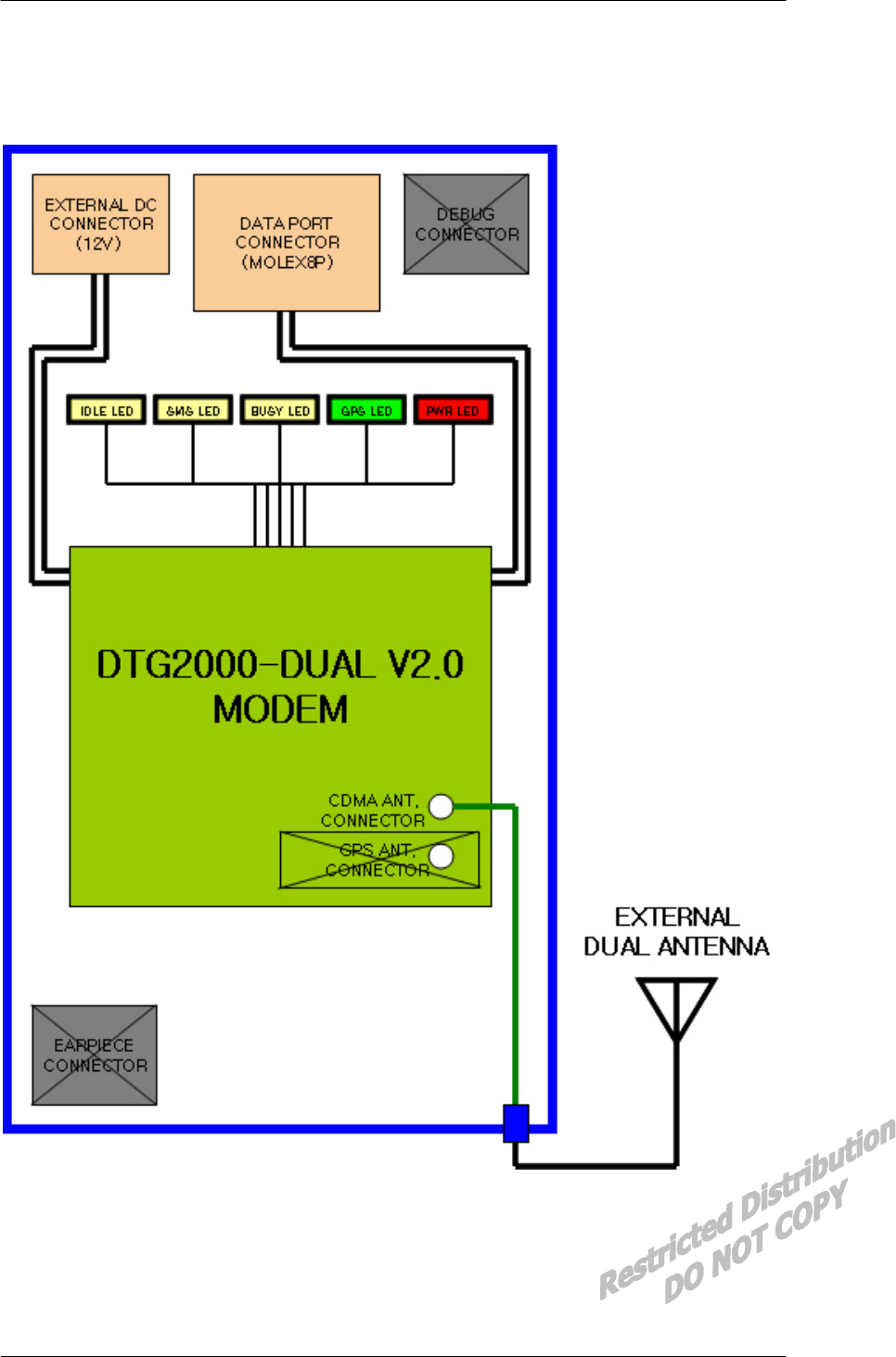
2.3 Interface Diagram
Figure 2-1 Interface Block Diagram
EMIV-DUAL V2.0 AnyDATA.NET Proprietary – Use Subject to Restrictions
Interface Description EMIV-DUAL V2.0 Reference Manual Application Information
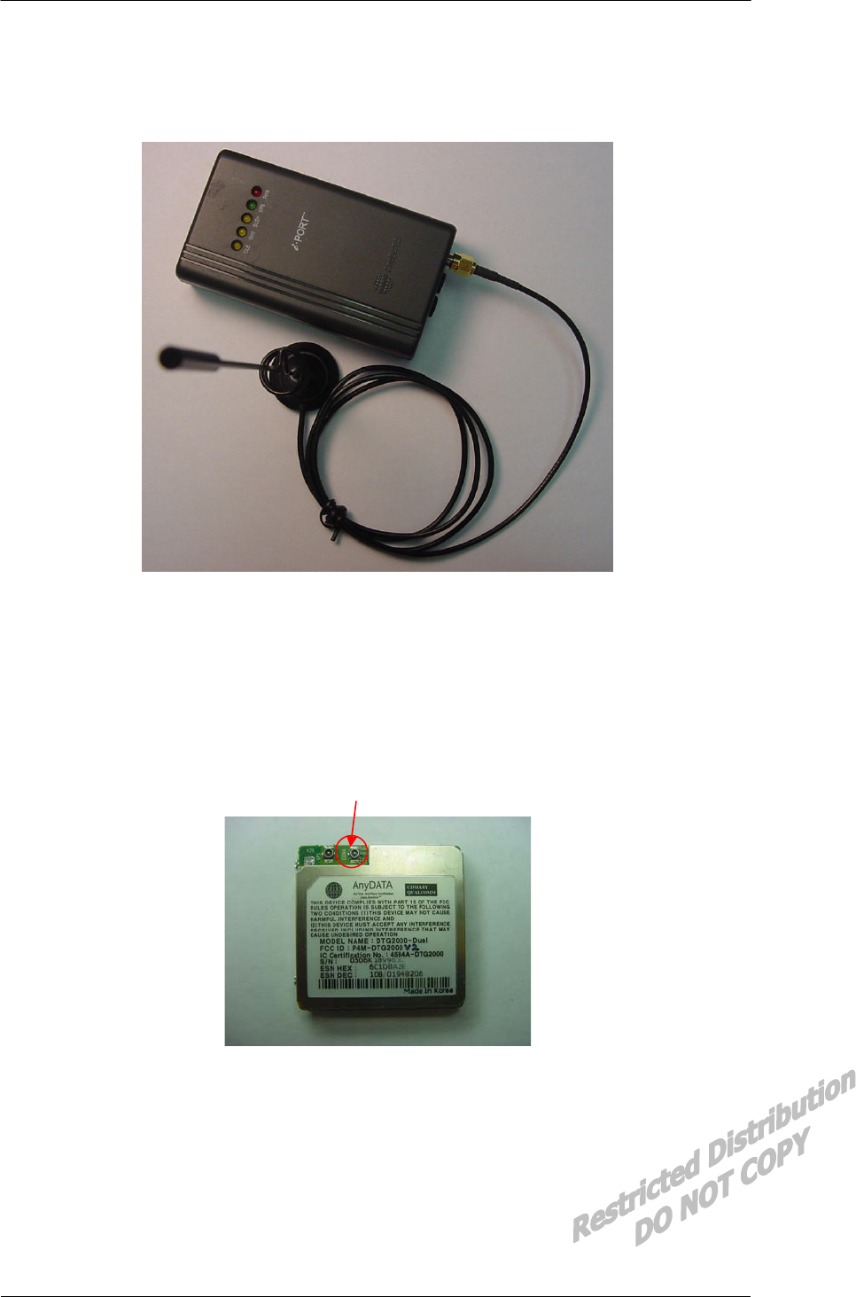
2.4 EMIV-DUAL V2.0 Photo
Figure 2-2 EMIV-DUAL V2.0 Photo
2.5 Internal Module Photo
CDMA Connector
Figure 2-3 Internal Module Photo (DTG2000-DUAL V2.0)
EMIV-DUAL V2.0 AnyDATA.NET Proprietary – Use Subject to Restrictions
Interface Description EMIV-DUAL V2.0 Reference Manual Application Information
3. PIN Description
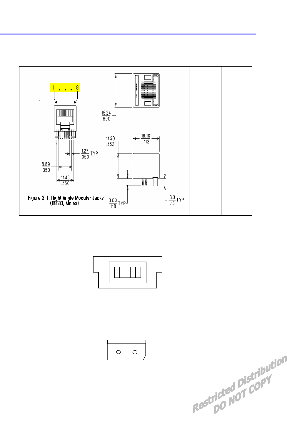
3.1 8-Pin Male Modular Jacks (RS232 Standard)
Molex
(85503)
RS-232
(Host)
Pin 1
Pin 2
Pin 3
Pin 4
Pin 5
Pin 6
Pin 7
Pin 8
RI
GND
DTR
CTS
TX
RTS
RX
DCD
Figure 3-1 Right Angle Modular Jacks Pin Description (85503,Molex 8P)
3.2 Debug Connector
VCC RXD TXD NC GND
Figure 3-2 Debugging Connector (UX60-MB-5S8)
3.3 DC Power Connector
DC 12V
-+
Figure 3-3 DC 12V Power Connector (5268, Molex 2P)
EMIV-DUAL V2.0 AnyDATA.NET Proprietary – Use Subject to Restrictions
Interface Description EMIV-DUAL V2.0 Reference Manual Application Information
4. Interface Descriptions
4.1 Overview
This chapter covers information required to design the EMIV-DUAL V2.0 into a subscriber unit
application. In addition, the internal signals that are necessary for complete understanding of the UART
interfaces are described below.
4.2 RS232 Interface (Standard)
The Universal Asynchronous Receiver Transmitter (UART) communicates with serial data that
conforms the RS-232 Interface protocol. The modem provides 5.0V CMOS level.
All the control signals of the RS-232 signals are active low, but data signals of RXD, and TXD Are
active high. The UART has a 64byte transmit (TX) FIFO and a 64byte receive (RX) FIFO. The UART
Features hardware handshaking, programmable data sizes, programmable stop bits, and odd, even, no
parity. The UART operates at a 115.2kbps maximum bit rate.
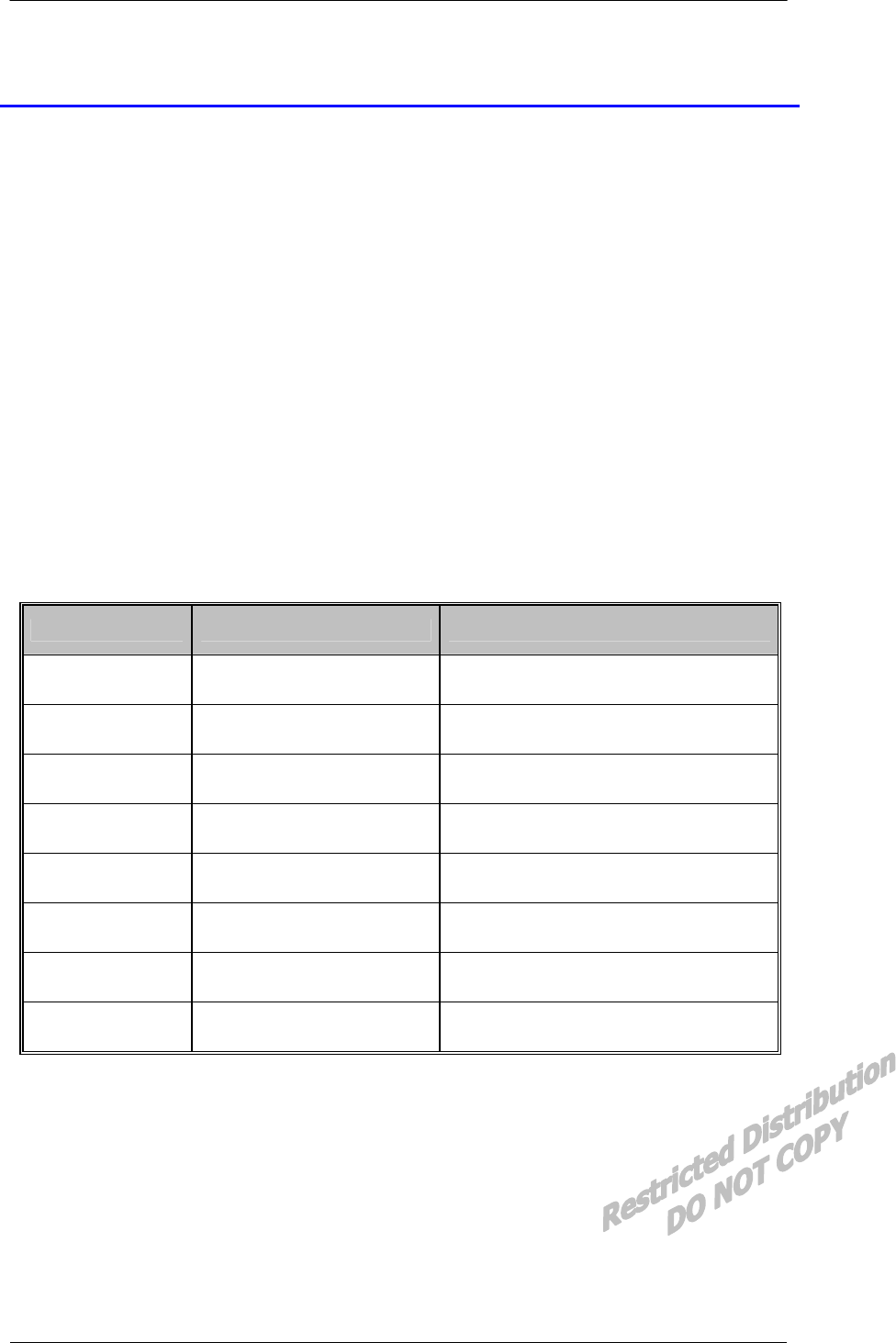
NAME DESCRIPTION CHARACTERISTIC
DP_DCD/ Data Carrier Detect Network connected from the modem
DP_RI/ Ring Indicator Output to host indicating coming call
DP_RTS/ Request to Send Ready for receive from host
DP_TXD Transmit Data Output data from the modem
DP_DTR/ Data Terminal Ready Host ready signal
DP_RXD Receive Data Input data to the modem
DP_CTS/ Clear to Send Modem output signal
GND Signal Ground Signal ground
Figure 4-1 UART Interface Pinout
EMIV-DUAL V2.0 AnyDATA.NET Proprietary – Use Subject to Restrictions
Interface Description EMIV-DUAL V2.0 Reference Manual Application Information
5. Electrical Specifications
5.1 Absolute Maximum Ratings
Operating the modem under conditions that exceed those listed in the Absolute Maximum. The
Ratings table may result in damage to the modem.
Absolute Maximum Ratings may be considered as limiting values, and are considered individually.
While all other parameters are within their specified operating ranges, the functional operation of the
modem under any of the conditions in the Absolute Maximum Ratings table is not implied.
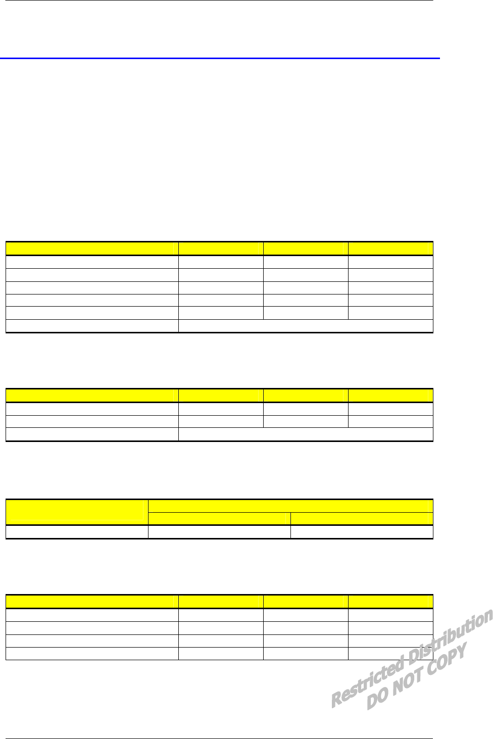
Table 5-1 Absolute Maximum Ratings
PARAMETER MIN MAX UNITS
Storage Temperature -40 +80 ºC
Voltage On Any Input - +20 V
Voltage On Any Output +10 V
Supply Voltage - +20 V
Initializing Current 100 mA
Drop No damages after 60-Inch drop over concrete floor
5.2 Recommended Operating Conditions
PARAMETER MIN MAX UNITS
Supply Voltage +7 +16 V
Operating Temperature -30 +60 ºC
Operating Humidity 95%(50ºC) Relative Humidity
5.3 Power Consumption
STANDBY
Conversation Idle Sleep
350mA (MAX) at 12V 70mA 30mA
5.4 Serial Interface Electrical Specifications
PARAMETER MIN MAX UNITS
Input High Voltage +2 +15 V
Input Low Voltage -15 -2 V
Output High Voltage +5 +7 V
Output Low Voltage -7 -5 V
EMIV-DUAL V2.0 AnyDATA.NET Proprietary – Use Subject to Restrictions
Interface Description EMIV-DUAL V2.0 Reference Manual Application Information
6. Mechanical Dimensions
6.1 EMIV-DUAL V2.0 Outline
EMIV-DUAL V2.0 AnyDATA.NET Proprietary – Use Subject to Restrictions
Interface Description EMIV-DUAL V2.0 Reference Manual Application Information
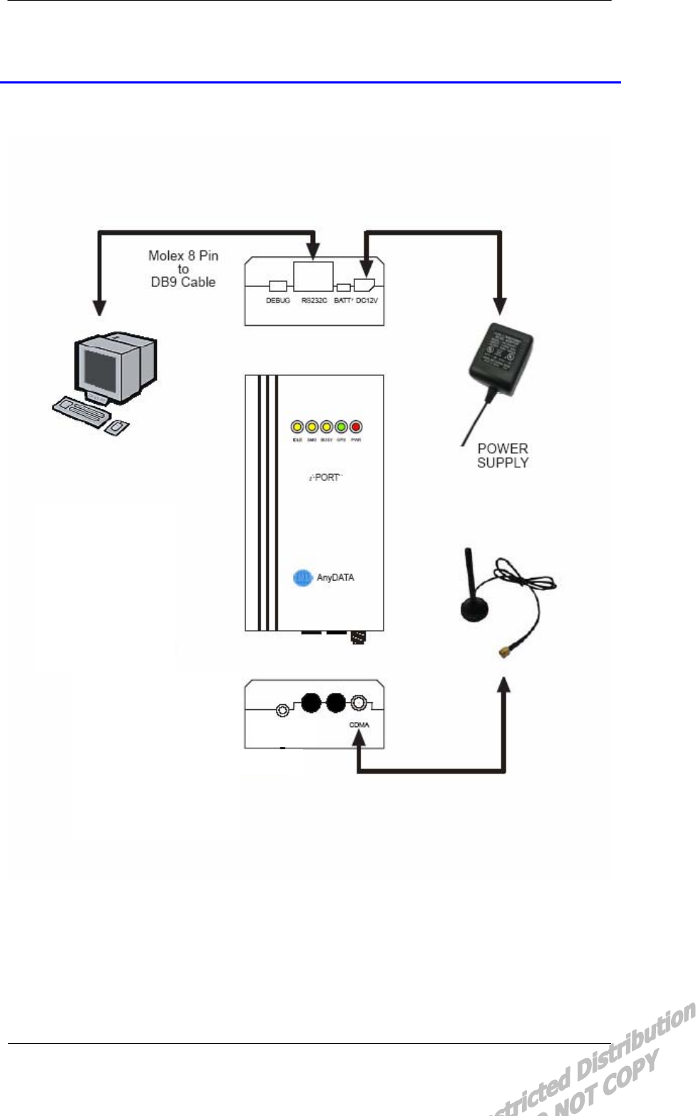
7. Installation Example
EMIV-DUAL V2.0 AnyDATA.NET Proprietary – Use Subject to Restrictions