Apc Smart Slot Ap9607 Users Manual Interface Expander User
Smart Slot AP9607 ASTE-6Z5Q9H_R0_EN
AP9607 to the manual ab101703-01dd-48b4-bc73-94fa0d75bfad
2015-02-03
: Apc Apc-Smart-Slot-Ap9607-Users-Manual-470975 apc-smart-slot-ap9607-users-manual-470975 apc pdf
Open the PDF directly: View PDF ![]() .
.
Page Count: 42

®
Interface
Expander
AP9607

Thank You!
Thank you for selecting the UPS Interface Expander (AP9607). It has been designed for
many years of reliable, maintenance-free service in combination with your American
Power Conversion (APC) uninterruptible power supply (UPS). APC is dedicated to the
development of high-performance electrical power conversion and control products. We
hope that you will find this product a valuable, convenient addition to your computing
system.
Please read this manual! It provides important safety, installation, and operating instruc-
tions that will help you get the most from your Interface Expander.
Save this manual! It includes instructions for obtaining warranty service.
Radio frequency interference
WARNING: Changes or modifications to this unit not expressly approved by the party
responsible for compliance could void the user’s authority to operate this equipment.
NOTE: This equipment has been tested and found to comply with the limits for a Class B
digital device, pursuant to part 15 of the FCC Rules. These limits are designed to provide
reasonable protection against harmful interference in a residential installation. This equip-
ment generates, uses and can radiate radio frequency energy and, if not installed and used
in accordance with the instructions, may cause harmful interference to radio communica-
tions. However, there is no guarantee that interference will not occur in a particular
installation. If this equipment does cause harmful interference to radio or television recep-
tion, which can be determined by turning the equipment off and on, try to correct the
interference by one or more of the following measures:
• Reorient or relocate the receiving antenna.
• Increase the separation between the equipment and receiver.
• Connect the equipment into an outlet on a circuit different from that to which the
receiver is connected.
• Consult the dealer or an experienced radio/TV technician for help.
Shielded communications cables must be used with this
unit to ensure compliance with the Class B FCC limits.
This Class B digital apparatus complies with Canadian ICES-003.
Cet appareil numérique de la classe B est conforme à la norme NMB-003 du Canada.

i
Contents
Introduction . . . . . . . . . . . . . . . . . . . . . . . . . . . . . . . . . . . . . . 1
Overview 1
Features of the Interface Expander 2
Hardware and software requirements 3
Choosing cables 4
Safety warning 4
Product Description . . . . . . . . . . . . . . . . . . . . . . . . . . . . . . . . 5
Interface Expander panel 5
Basic monitoring ports 5
Configuration DIP switches 5
Status LED 6
Key Concepts . . . . . . . . . . . . . . . . . . . . . . . . . . . . . . . . . . . . . 7
Simple versus smart signaling 7
Master server versus Interface Expander servers 8
Configuring PowerChute plus for simple signaling 9
Low Battery signal 10
Scheduled shutdowns 10
Setup overview 11
Multiple SmartSlot Installation . . . . . . . . . . . . . . . . . . . . . . . . 12
Introduction 12
Priority of SmartSlot devices 12
If your UPS has one SmartSlot accessory slot 13
Installation in the APC Triple Chassis 13
Installation in the Symmetra PowerArray 14
Daisy chains 14
Installation . . . . . . . . . . . . . . . . . . . . . . . . . . . . . . . . . . . . . . 15
Warning 15
Reminder 15
Installation procedure 15

ii
Contents continued
Connecting to Protected Devices . . . . . . . . . . . . . . . . . . . . . . 17
Connection procedure 17
Connecting the Interface Expander 18
Configuring the Interface Expander . . . . . . . . . . . . . . . . . . . 19
Shutdown modes 19
DIP switches 19
Confirmed shutdown mode 20
PowerChute plus support for Confirmed
shutdown mode 20
Behavior of Confirmed mode 21
Confirmed shutdown mode and the Advanced port 21
Until Low Battery shutdown mode 22
Timer shutdown mode 22
Testing the Interface Expander 23
Warranty Information . . . . . . . . . . . . . . . . . . . . . . . . . . . . . . 24
Limited warranty 24
Obtaining service 24
Warranty limitations 25
Troubleshooting . . . . . . . . . . . . . . . . . . . . . . . . . . . . . . . . . . 26
If you have problems with your Interface Expander 26
Troubleshooting 26
If problems persist 28
Life-Support Policy . . . . . . . . . . . . . . . . . . . . . . . . . . . . . . . . 29
General policy 29
Examples of life-support devices 29
Specifications . . . . . . . . . . . . . . . . . . . . . . . . . . . . . . . . . . . . 30
Basic port pin assignments 30
Basic port pin assignments 31
Product specifications 32

1
Introduction
Overview The UPS Interface Expander (AP9607) is an American
Power Conversion (APC) SmartSlot™ accessory that pro-
vides two additional computer interface ports for your APC
UPS equipped with a SmartSlot accessory slot. It allows the
UPS to work in conjunction with your power management
software to provide safe system shutdown in extended
power outages for up to three network servers or other
devices.
Since the computer interface port of the UPS remains avail-
able while using the Interface Expander, it is possible to
provide advanced UPS and power management functions to
all protected devices. You can provide power management
with APC PowerChute© plus software and UPS accessories
such as the APC Web/SNMP Management Card (AP9606)
for network connectivity and the Call-UPS©II (AP9208,
AP9608) remote management device.
The Interface Expander draws power from the UPS. It
monitors the UPS and reports power conditions (e.g., On
Battery, Low Battery, On Line) to all attached devices.
Continued on next page

2
Introduction continued
Features of
the Interface
Expander
The Interface Expander:
• Mounts in all APC devices equipped with a SmartSlot
accessory slot.
• Works well in a heterogeneous network. Servers run-
ning different operating systems can monitor the
same UPS simultaneously.
• Supports advanced or simple signaling on the
advanced port of the UPS.
• Can delay shutdown of the UPS until all servers have
shut down gracefully.
• Allows you to restart hung servers.
• Has operating modes that cause the UPS to shut down
after confirmation from all protected devices or after
an interval set by the user. See “Configuring the
Interface Expander” on page 19.
• Does not depend on the operation of the network to
protect connected devices. As a hard-wired acces-
sory, the Interface Expander reliably conveys impor-
tant status messages during poor power conditions.
Continued on next page

3
Introduction continued
Hardware and
software
requirements
The Interface Expander requires:
•An
APC device equipped with a SmartSlot accessory
slot. SmartSlot devices include—but are not limited
to—the APC UPSs in the next item.
•An
APC UPS of one the following models:
–Smart-
UPS®, except models AP250, AP400,
AP600, AP900, AP1250, AP2000, SUVS420,
SUVS650, SUVS1000, SUVS1400, SU620.
–Matrix-
UPS™, except models with serial numbers
less than x9412.
– Symmetra™ PowerArray™.
•APC PowerChute software (simple signaling) or
PowerChute plus (advanced or simple signaling) soft-
ware. See “Simple versus smart signaling: Table 3”
on page 7.
• A serial cable (for each connected device) that moni-
tors shutdown signals. See “Choosing cables: Table
1” on page 4.
Continued on next page

4
Introduction continued
Choosing
cables:
Table 1
This table lists the cables for use with the systems supported
by the Interface Expander. When ordering a cable, provide
the Part Number.
Safety warning The Interface Expander is to be used only in conjunction
with an APC UPS. Use only APC UPS monitoring cables.
Do not connect a computer to any Interface Expander port
using a “straight-through” wired extending cable. Connec-
tions using a UPS or cable made by any other manufacturer
may cause damage or improper operation of the the Inter-
face Expander unit, the UPS, or the computer.
Do not operate the Interface Expander where the ambient
temperature or humidity is outside the limits listed in “Prod-
uct specifications: Table 7” on page 32.
IF you want to
connect the Interface
Expander to a(n)… THEN order… Part
Number
Windows or NetWare
server
UPS LAN Mana
g
er Cable 940-0020
UNIX server UNIX Basic Si
g
nalin
g
Cable
AP9823
IBM AS/400 AS/400 Cable Model 9402/
9404
940-0006
Macintosh A
pp
le-
Share server
PowerChute for Macintosh
(software and cable)
AP9001
15-ft extension cable UPS Interface Extension AP9815
50-ft extension cable Isolated Extension Cable AP9825
Table 1: Choosing cables
5
Product Description
Interface
Expander panel:
Figure 1
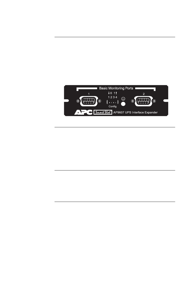
The following figure shows the front panel of the Interface
Expander. The panel contains:
• 2 Basic monitoring ports
• 4 Configuration DIP switches
• a status LED
Figure 1:Interface Expander panel
Basic
monitoring
ports
The two computer interface ports on the Interface Expander
are called Basic ports because they supply simple UPS sig-
naling for On Battery and Low Battery conditions in the
UPS. For further information see “Simple versus smart sig-
naling: Table 3,” on page 7.
Configuration
DIP switches
The Interface Expander Configuration DIP switches control
the shutdown operation of the unit. See “Configuring the
Interface Expander” on page 19.
Continued on next page

6
Product Description continued
Status LED:
Table 2
The Interface Expander status LED provides important
information concerning operation of the unit. Refer to the
table below for a description of the conditions indicated by
the LED.
Status Description
On Normal o
p
eration. The Interface
Ex
p
ander is on and communicatin
g
with the UPS.
Mostl
y
on, with a sin
g
le
blink off
The Interface Ex
p
ander is si
g
nalin
g
a
UPS On Batter
y
condition to the con-
nected servers.
Mostl
y
on, with two
blinks off
The Interface Ex
p
ander is si
g
nalin
g
On Batter
y
and Low Batter
y
condi-
tions to the connected servers, and will
eventuall
y
shut down the UPS.
Flashin
g
continuousl
y
Shutdown of the UPS is imminent.
Mostl
y
off, with a sin
g
le
flash on
UPS out
p
uts are off—UPS is in Slee
p
mode.
Blinkin
g
slowl
y
and
continuousl
y
The Interface Ex
p
ander failed its self-
test.
Off The Interface Ex
p
ander is
p
owered off
or is not able to communicate with the
UPS.
Table 2: Status LED

7
Key Concepts
Simple versus
smart signaling:
Table 3
The communication between an APC UPS and a connected
server can be of two types: simple signaling or smart signal-
ing. This table provides information that distinguishes the
two types.
Continued on next page
Item Communication Types
Simple Signaling Smart Signaling
UPS mon-
itorin
g
features
–On Batter
y
si
g
nal
–Low Batter
y
si
g
nal
–On Batter
y
si
g
nal
–Low Batter
y
si
g
nal
–Continuous advanced
monitorin
g
visible in
PowerChute plus
g
ra
p
hs
Software
used
PowerChute
(or PowerChute plus
confi
g
ured for sim
p
le
si
g
nalin
g
)
PowerChute plus
confi
g
ured for smart si
g
-
nalin
g
Port t
yp
e Basic Advanced or Basic
UPS
models
su
pp
orted
–Back-UPS
–Smart-UPS†
–Matrix-UPS
–S
y
mmetra PowerArray
† See “Hardware and software requirements,” on pa
g
e 3
for a listin
g
of APC UPSs that do not support simple
si
g
nalin
g
with the Interface Expander.
–Smart-UPS,
–Matrix-UPS, and
–S
y
mmetra PowerArray
Communi-
cation
cables
Cables in the interface
kit associated with each
OS. See “Choosin
g
cables: Table 1” on
p
a
g
e
4.
Cable su
pp
lied with
PowerChute plus
Table 3: Simple versus smart signaling

8
Key Concepts continued
Master server
versus Interface
Expander
servers
A “master” server is a server connected to the (Advanced)
computer interface port of the UPS. This server uses
PowerChute plus, configured for smart signaling, to moni-
tor and control the UPS. Although the Advanced port on the
UPS can provide simple signaling, we strongly recommend
using it for smart signaling with the advanced capabilities of
PowerChute plus.
Servers connected to the Basic ports of the Interface
Expander use simple signaling with PowerChute or
PowerChute plus to provide UPS shutdown capabilities and
advanced notification features. If you are running
PowerChute plus on these servers, you must configure it for
simple signaling. See “Configuring PowerChute plus for
simple signaling” on page 9.
Continued on next page

9
Key Concepts continued
Configuring
PowerChute plus
for simple
signaling
To use PowerChute plus on a server connected to the Inter-
face Expander, configure PowerChute plus for simple
signaling. Use either one of these procedures.
1 (Re)install PowerChute plus. When the installation
program prompts for the UPS Type, select “Back-
UPS” and continue with the installation, including
a reboot of the system.
2 Run PowerChute plus and connect to the UPS.
3 Verify that the status line on the PowerChute plus
screen shows “On Line.” Proceed with Step 4
below.
OR
1 With PowerChute plus running, select Communi-
cation Parameters from the Configuration
menu.
2Click
Simple Signalling. Click OK.
3 Close PowerChute plus.
4If the UPS had previously been connected using
smart signaling:
a Unplug the UPS.
b Turn off the UPS output by pressing the Off
button for at least 5 seconds.
c Change communication cables, using the sim-
ple signaling cable from the interface kit. (See
“Choosing cables: Table 1” on page 4.)
5 Restart PowerChute plus and attach the server to
the UPS.
6 Verify that the status of the UPS on the
PowerChute plus screen shows “On Line.”
Continued on next page

10
Key Concepts continued
Low Battery
signal
The Interface Expander generates a Low Battery signal
when it detects a Low Battery condition at the UPS, regard-
less of whether the UPS is on battery. The Interface
Expander generates a Low Battery signal under certain
other conditions according to the configured shutdown
mode (see “Configuring the Interface Expander” on page
19), when it may force a Low Battery signal and an On Bat-
tery signal, causing the servers to shut down.
Scheduled
shutdowns
When a server connected to the (Advanced) computer inter-
face port on the UPS is running UPS-monitoring software
such as PowerChute plus, you can execute scheduled or
supervised UPS shutdowns for the servers connected to the
Interface Expander. The Interface Expander intercepts the
shutdown signal and sends the following messages to all
attached servers or devices:
• On Battery and Low Battery signals (for the low-bat-
tery duration set in the UPS)
• Shutdown commands (e.g., Sleep, Turnoff, etc., as
requested by PowerChute plus)
The servers connected to the Basic ports to shut down
gracefully before they lose power when the UPS output is
turned off—a feature normally available only to servers
using PowerChute plus and smart signaling.
Continued on next page

11
Key Concepts continued
Setup overview To set up the Interface Expander, you will be required to
perform the following procedures as applicable:
1 Determine which SmartSlot accessory slot you
will use for the Interface Expander. See “Multiple
SmartSlot Installation” on page 12.
2 Install the Interface Expander into the SmartSlot
accessory slot of the UPS or other device. See
“Installation” on page 15.
3 Connect the protected devices. See “Connecting to
Protected Devices” on page 17.
4 Configure the Interface Expander for automatic
shutdown. See “Configuring the Interface
Expander” on page 19.
5 Test the operation of the Interface Expander. See
“Testing the Interface Expander” on page 23.
12
Multiple SmartSlot Installation
Introduction If your UPS configuration uses more than one SmartSlot
device, you must install them in the correct order for them
to work together properly.
Priority of
SmartSlot
devices:
Table 4
Install SmartSlot accessories as dictated by the following
table. An accessory with higher priority is to be placed in
the accessory slot with the higher number.
Note: The Share-UPS accessory (AP9207) has the same
priority as the Interface Expander. For information
on accessories that are not listed, see the documenta-
tion provided with the accessory.
Continued on next page
Accessory P/N Priority Position
PowerNet
SNMP Ada
p
ter
or Web/SNMP
Mana
g
ement
Card
AP9605
AP9603
AP9606
Hi
g
hest Hi
g
h-numbered slot
Low-numbered slot
Call-UPS®II AP9608 Second-
hi
g
hest
Rela
y
I/O
Module
AP9610 Third-
hi
g
hest
Interface
Ex
p
ander
AP9607 Second
lowest
Measure-UPS®
II
AP9612T
AP9612TH Lowest
Table 4: Priority of SmartSlot devices
13
Multiple SmartSlot Installation continued
If your UPS has
one SmartSlot
accessory slot
If your UPS has exactly one SmartSlot accessory slot, use
this accessory slot for the SmartSlot device with the lowest
priority. Install SmartSlot devices with higher priority in an
Expansion Chassis (AP9600) or Triple Chassis (AP9604—
see “Installation in the APC Triple Chassis” on this page).
If you are using a Symmetra PowerArray, see “Installation
in the Symmetra PowerArray” on page 14.
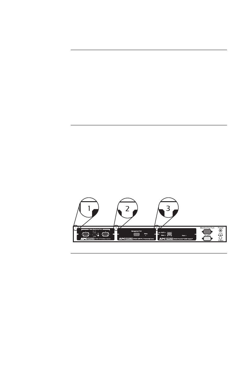
Installation in
the APC Triple
Chassis
To install SmartSlot devices in the APC Triple Chassis
(AP9604), note that the slots are numbered on the rear
panel. The following figure shows the rear panel of the
Triple Chassis with the PowerNet SNMP Adapter installed
in slot #3, Call-UPSII in slot #2, and the Interface Expander
in slot #1. (In this scenario, Measure-UPSII could be
installed in the accessory slot of the UPS.)
Continued on next page
14
Multiple SmartSlot Installation continued
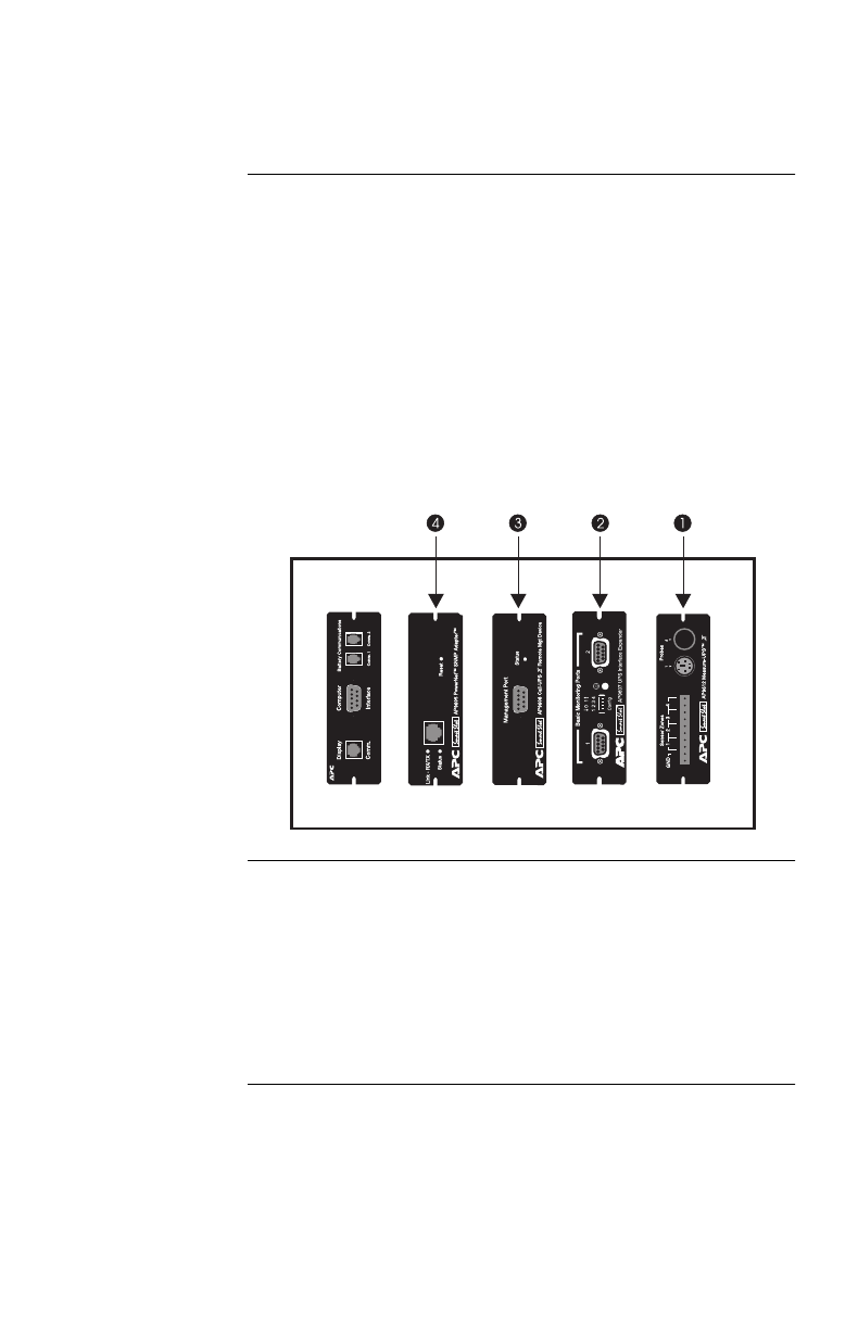
Installation in
the Symmetra
PowerArray
For installation of multiple SmartSlot devices in the Sym-
metra PowerArray, refer to the numbering shown in the
figure that follows. Note that the PowerNet SNMP Adapter
is installed in slot #4, Call-UPSII in #3, the Interface
Expander in #2, and Measure-UPSII in #1.
If you are using an external SmartSlot housing (Expansion
Chassis or Triple Chassis) in conjunction with a Symmetra
Power Array, install the devices with higher priority in the
external slot(s). Refer to “Installation in the APC Triple
Chassis” on page 13, if applicable.
Daisy chains If you have increased your SmartSlot capacity by daisy-
chaining Expansion Chassis or Triple Chassis, install the
PowerNet SNMP Adapter (or Web/SNMP Management
Card) and Call-UPSII in the highest-numbered and second-
highest-numbered slots, respectively, of the chassis installed
farthest from the UPS.
15
Installation
Warning Handle the Interface Expander by the front panel. Do not
touch the exposed printed circuit board or components.
Touching the circuit board or components may result in
damage to the Interface Expander.
Reminder Before you install the Interface Expander, install any
required power management software (PowerChute, Power-
Chute plus, or software required by your operating system).
If you plan to use PowerChute plus on servers connected to
the Basic ports of the Interface Expander, see “Master
server versus Interface Expander servers” on page 8 and
“Configuring PowerChute plus for simple signaling” on
page 9.
Installation
procedure
To install the Interface Expander, perform the following
steps in the order given.
Note: If your UPS configuration uses more than one
SmartSlot device, refer to “Multiple SmartSlot Instal-
lation” on page 12 before proceeding.
1 Turn off the UPS or device that will house the
----Interface Expander. To turn off the UPS:
a Unplug the UPS.
b Turn off the UPS output by pressing the
Off button for at least 5 seconds.
2 Unpack the Interface Expander. The shipping
materials are recyclable. Please reuse or dispose of
them appropriately.
3 Use a #2 Phillips head screwdriver to remove the
two screws fastening the accessory slot cover on
the back panel of the UPS or device. Keep the
screws for Step 5 below. Save the accessory slot
cover for future use (e.g., shipping the UPS).
Continued on next page
16
Installation continued
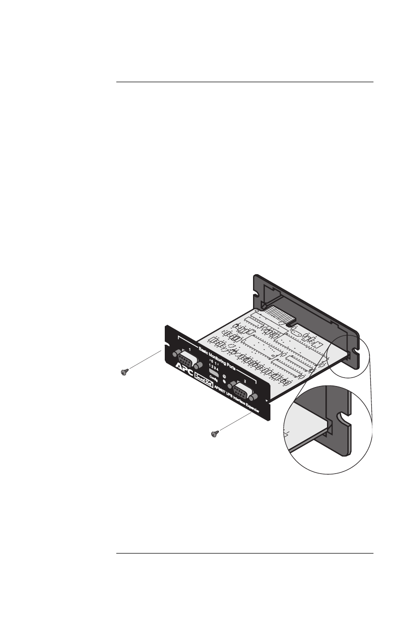
Installation
procedure,
continued
4 Orient the Interface Expander to fit the accessory
slot. Slide the Interface Expander all the way into
the slot until the front panel is flush with the back
panel of the UPS or device.
Note: While it is not possible to install the Inter-
face Expander upside down, it is possible to
damage the unit in the attempt to do so.
Observe the correct orientation as shown
below. Note that the sides of the printed cir-
cuit board align with the card guides in the
sides of the accessory slot. The accessory
slot in the UPS or device may be oriented
horizontally or vertically.
5 Secure the Interface Expander with the screws
removed in Step 3.
6 Proceed with “Connecting to Protected Devices”
on page 17.

17
Connecting to Protected Devices
Connection
procedure
To connect the devices, refer to “Connecting the Interface
Expander: Figure 2” on page 18 and perform the following
steps in the order given.
1 Connect the master server to the (Advanced) com-
puter interface port of the UPS. (See “Master
server versus Interface Expander servers” on page
8.)
Note: A server not supported by PowerChute plus
must use simple signaling with the appropri-
ate cable. (See “Choosing cables: Table 1”
on page 4.)
If an accessory, such as Call-UPS II or
Measure-UPS II, is already using the
(Advanced) computer interface port of the
UPS, connect the master server to the UPS
monitoring port on the accessory. (Accesso-
ries label this port in different ways, but the
function—replicating the computer inter-
face port of the UPS—is the same.)
2 Connect the other server(s) to the Basic ports on
the Interface Expander, using APC cables. See
“Choosing cables: Table 1” on page 4.
Note: Servers connected to the Basic ports of the
Interface Expander use simple signaling
for monitoring the UPS. If these servers use
PowerChute plus, this software must be
configured for simple signaling. See “Con-
figuring PowerChute plus for simple
signaling” on page 9.
3 Connect the power cords of all protected servers
and devices to the power outlets on the UPS.
4 Continue with “Configuring the Interface
Expander” on page 19.
Continued on next page


19
Configuring the Interface Expander
Shutdown
modes
To configure the Interface Expander, you must choose one
of the three available modes of automatic UPS shutdown.
Each shutdown mode is described in this section.
• Confirmed
• Until Low Battery
•Timer
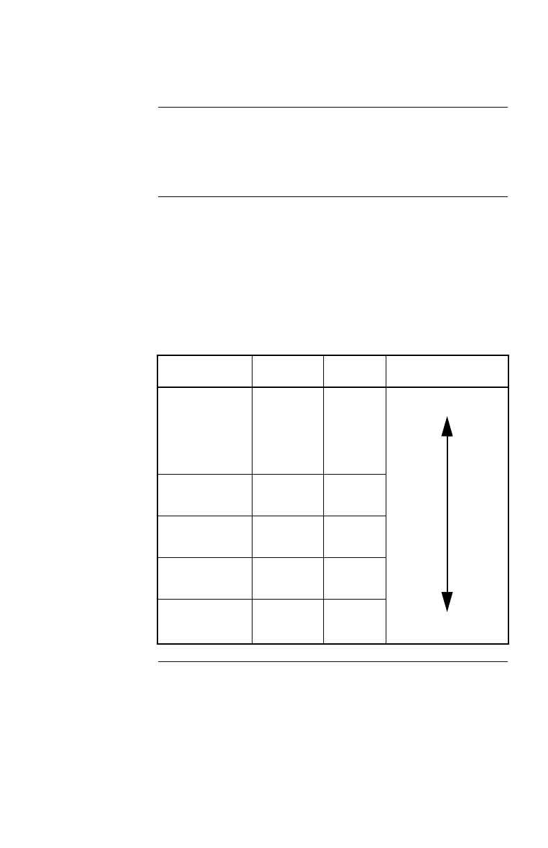
DIP switches:
Table 5
Select the shutdown mode by using the DIP switches as
described in the following table. (An abbreviated form of
his table also appears on the bottom side of the Interface
Expander circuit board.)
Continued on next page
Shutdown Mode Switch Setting (↓=0, ↑ =1)
1234
Confirmed 0 0 0 *
Until Low Batter
y
001
N/A
Timer
2 min. 0 1 0 N/A
5 min. 0 1 1 N/A
10 min. 1 0 0 N/A
15 min. 1 0 1 N/A
30 min. 1 1 0 N/A
60 min. 1 1 1 N/A
* Server on
Advanced Port
Await
Confirmation 0000
Treat as
Confirmed 0001
Table 5: DIP switches

20
Configuring the Interface Expander continued
Confirmed
shutdown mode
In Confirmed mode, the Interface Expander shuts down the
UPS after all connected servers have signaled that they have
completed shutdown of the operating system.
Note: Do not use Confirmed mode if any server connected
to the Interface Expander Basic ports or the UPS
Advanced port is incapable of sending a shutdown
confirmation signal. See “PowerChute plus support
for Confirmed shutdown mode” on this page.
PowerChute plus
support for
Confirmed
shutdown mode
Some versions of PowerChute plus do not support Con-
firmed shutdown mode when set up for simple signaling.
Other versions require some editing of the pwrchute.ini file
in the PowerChute plus installation directory. To find out
whether your version of PowerChute plus supports Con-
firmed shutdown mode, go to http://support.apcc.com/ and
find the link to “What Versions of PowerChute plus Support
Confirmed Shutdown Mode?” under Preinstallation Infor-
mation|SmartSlot Device|Installation Planning.
Continued on next page

Configuring the Interface Expander continued
Behavior of
Confirmed mode
If power returns before any connected server has signaled
shutdown of the operating system, the Interface Expander
returns to On Line status.
If the Interface Expander detects a Low Battery condition in
the UPS before all connected servers have signaled shut-
down of the operating system, it notifies the servers that the
UPS battery is exhausted, shutting down the UPS after the
Low Battery Signal Time has elapsed.
If utility power returns after at least one server has con-
firmed shutdown of the operating system, but before all
servers have confirmed system shutdown, the Interface
Expander forces On Battery and Low Battery signals so that
the remaining servers shut down as well. The Interface
Expander sends the forced Low Battery signal for a period
of time equal to the Low Battery Signal Time and then shuts
down the UPS, which cycles power to restart the servers.
Confirmed
shutdown mode
and the
Advanced port
If you configure the Interface Expander in Confirmed shut-
down mode by setting DIP switches 1, 2, and 3 in the down
(0) position, you must set DIP switch #4 to determine the
behavior of the server or device connected to the Advanced
port.
When the Interface Expander is configured for Confirmed
mode, DIP switch #4 behaves as follows:
• With DIP switch #4 in the 0 (down) position, the
Advanced port operates normally, awaiting shutdown
confirmation in the Confirmed shutdown mode.
• With DIP switch #4 in the 1 (up) position, the Inter-
face Expander treats the Advanced port as always
confirmed. Use this setting when the Advanced port
will not be receiving a shutdown confirmation signal.
Note:When the shutdown mode of the Interface Expander is
set to Until Low Battery or Timer, the position of DIP switch
#4 has no effect.
Continued on next page

22
Configuring the Interface Expander continued
Until Low
Battery
shutdown mode
Until Low Battery shutdown mode is similar to the standard
operation of the UPS. During a utility failure, the Interface
Expander allows the UPS to run on battery until utility
power is restored, or until the battery is exhausted. If the
Interface Expander detects a UPS Low Battery condition, it
sends a Low Battery signal on all ports for a period of time
equal to the Low Battery Signal Time and then shuts down
the UPS.
If utility power returns after the Low Battery timer has
begun, the Interface Expander will continue the countdown
and force the UPS to cycle power.
This mode is useful for applications which require maxi-
mum run time.
Timer shutdown
mode
In Timer shutdown mode, the Interface Expander allows the
UPS to operate on battery for a user-specified length of time
before shutting down the UPS. See “DIP switches: Table 5”
on page 19 for the available timer settings.
If power returns before the timer has run out, the Interface
Expander returns to On Line status. When the timer runs out
or when the Interface Expander detects a Low Battery con-
dition in the UPS, the Interface Expander sends a Low
Battery signal for a period of time equal to the Low battery
signal time and then shuts down the UPS.
Note: If you are using PowerChute software, set the shut-
down delay for a time longer than the Interface
Expander timer setting. Otherwise, if the power
returns after the server shuts down, the server may
not restart. To set the shutdown delay, go to Configu-
ration|Event Actions and select UPS On Battery
from the Event list and Shut Down Server in the
Action box. Click Options and enter a setting for
Begin Shutdown Sequence in __ Seconds. Click OK.
Continued on next page

23
Configuring the Interface Expander continued
Testing the
Interface
Expander
To check the operation of the Interface Expander, perform
the following steps in the order given.
1 Confirm that the UPS in on and that the battery is
fully charged.
2 Verify that the Interface Expander has been
installed, connected, and configured.
3 Confirm that all connected servers and devices are
on and running their power management software
with power management screens visible, if appli-
cable.
4 Confirm that the status LED on the Interface
Expander is on, indicating normal operation.
5 Simulate a utility power failure.
6 Confirm that the status LED of the Interface
Expander is mostly on with a single blink off, indi-
cating that the Interface Expander is sending an
On Battery signal to the connected servers or
devices. See “Status LED: Table 2” on page 6.
7 Confirm that all connected servers and devices
have received the On Battery message from the
Interface Expander.
8 Restore utility power.
9 Confirm that all connected servers and devices
have received the message that utility power has
been restored.
Note: To check the shutdown mode of your config-
uration, keep the utility power off long
enough to allow all connected servers and
devices to shut down. After all connected
servers and devices have shut down, restore
power and verify that they all restart.

24
Warranty Information
Limited
warranty
American Power Conversion (APC) warrants the Interface
Expander to be free from defects in materials and workman-
ship for a period of two years from the date of purchase. Its
obligation under this warranty is limited to repairing or
replacing, at its own sole option, any such defective prod-
ucts. This warranty does not apply to equipment which has
been damaged by accident, negligence, or misapplication or
has been altered or modified in any way. This warranty
applies only to the original purchaser.
Obtaining
service
To obtain service under warranty you must obtain a
Returned Material Authorization (RMA) number from APC
or a designated APC service center. Products must be
returned to APC or an APC service center with transporta-
tion charges prepaid and must be accompanied by a brief
description of the problem encountered and proof of date
and place of purchase.
Continued on next page

25
Warranty Information continued
Warranty
limitations
Except as provided herein, American Power Conversion
makes no warranties, express or implied, including war-
ranties of merchantability and fitness for a particular
purpose. Some jurisdictions do not permit limitation or
exclusion of implied warranties; therefore, the aforesaid
limitation(s) or exclusion(s) may not apply to the purchaser.
Except as provided above, in no event will APC be liable
for direct, indirect, special, incidental, or consequential
damages arising out of the use of this product, even if
advised of the possibility of such damage.
Specifically, APC is not liable for any costs, such as lost
profits or revenue, loss of equipment, loss of use of equip-
ment, loss of software, loss of data, costs of substitutes,
claims by third parties, or otherwise. This warranty gives
you specific legal rights and you may also have other rights
which vary from state to state.

26
Troubleshooting
If you have
problems with
your Interface
Expander
The troubleshooting chart (Table 6) covers many of the
problems that might arise with the Interface Expander. If
you encounter a problem with your Interface Expander,
refer to the troubleshooting chart first. There may be a sim-
ple solution you are overlooking.
Trouble-
shooting:
Table 6
The following table shows the solution to common prob-
lems with the operation of the Interface Expander.
Continued on next page
Problem Possible Cause Solution
A server con-
nected to a Basic
p
ort does not
acknowled
g
e On
Batter
y
si
g
nal.
The wron
g
cable is
bein
g
used.
Verif
y
that the cable is
the one su
pp
lied with
y
our interface kit. See
“Choosin
g
cables:
Table 1” on
p
a
g
e 4.
There is an inter-
nal
p
roblem with
the Interface
Ex
p
ander.
Remove the Interface
Ex
p
ander tem
p
oraril
y
from the UPS and rein-
stall. If the
p
roblem
p
ersists, see “If
p
rob-
lems
p
ersist,” on
p
a
g
e
28.
Status LED
flashes continu-
ousl
y
.
There is an inter-
nal
p
roblem with
the Interface
Ex
p
ander.
Remove the Interface
Ex
p
ander tem
p
oraril
y
from the UPS and rein-
stall. If the
p
roblem
p
ersists, see “If
p
rob-
lems
p
ersist,” on
p
a
g
e
28.
Table 6: Trouble-shooting

27
Troubleshooting continued
Trouble-
shooting:
Table 6,
continued
Continued on next page
Problem Possible Cause Solution
One or more
servers shuts
down when the
UPS is on bat-
ter
y
, but does not
restart when
p
ower returns.
Timer mode: the
o
p
eratin
g
s
y
stem
shutdown time as
set in PowerChute
plus is too short.
The
p
ower mana
g
e-
ment software shut-
down time must be set
lon
g
er than the Inter-
face Ex
p
ander Timer
shutdown mode set-
tin
g
.
Confirmed mode:
the Interface
Ex
p
ander did not
receive shutdown
confirmation from
servers that shut
down, and utilit
y
p
ower was restored.
The server shut
down but the UPS
did not shut down.
Verif
y
that the servers
can confirm
shutdown. See “Pow-
erChute plus su
pp
ort
for Confirmed shut-
down mode” on
p
a
g
e
20. If not, confi
g
ure
the Interface Ex
p
ander
for Timer or Until
Low Batter
y
shut-
down mode.
The server on
UPS Advanced
p
ort cannot com-
municate with
the UPS.
The communica-
tion cable is not
p
ro
p
erl
y
fastened.
Verif
y
cable connec-
tions. See “Choosin
g
cables: Table 1” on
p
a
g
e 4.
The wron
g
cable is
bein
g
used.
Verif
y
that the cable is
correct for this server.
The master server is
connected to the
Interface Ex
p
ander.
The master server
must be connected to
the com
p
uter inter-
face (Advanced)
p
ort
on the UPS.
The
p
ort on the
master server is
bein
g
used b
y
another a
pp
lication.
Close the offendin
g
a
pp
lication.

28
Troubleshooting continued
If problems
persist
For problems not covered in the troubleshooting chart (see
“Troubleshooting: Table 6” on page 26), or if the problem
persists, follow this procedure:
1 Note the serial number and date of purchase of
the Interface Expander unit. Contact APC Cus-
tomer Support at the phone number or address on
the back cover of this manual.
2 Be prepared to provide a description of the prob-
lem. A technician will help solve the problem over
the phone, if possible, or will give you a return
material authorization (RMA) number.
3 If the Interface Expander unit is under warranty,
repairs are free of charge. If the warranty has
expired, there will be a nominal charge for repair.
4 Pack the Interface Expander carefully in its origi-
nal packaging, if possible. Do not use polystyrene
beads for packing. Damage sustained in transit is
not covered under the warranty. Enclose a letter in
the package with your name, address, RMA num-
ber, a copy of the sales receipt, daytime phone
number, and check (if applicable).
5 Mark the RMA number clearly on the outside of
the shipping carton. The factory will not accept
any materials without this marking.
6 Return the Interface Expander unit by insured, pre-
paid carrier to the U.S. address on the back cover
of this manual.

29
Life-Support Policy
General policy As a general policy, APC does not recommend the use of
any of its products in life support applications where failure
or malfunction of the APC product can be reasonably
expected to cause failure of the life support device or to
affect significantly its safety or effectiveness. APC does not
recommend the use of any of its products in direct patient
care. APC will not knowingly sell its products for use in
such applications unless it receives in writing assurances
satisfactory to APC that (a) the risks of injury or damage
have been minimized, (b) the customer assumes all such
risks, and (c) the liability of American Power Conversion is
adequately protected under the circumstances.
Examples of life-
support devices
Life support devices include but are not limited to neonatal
oxygen analyzers, nerve stimulators (whether used for anes-
thesia, pain relief, or other purposes), autotransfusion
devices, blood pumps, defibrillators, arrhythmia detectors
and alarms, pacemakers, hemodialysis systems, peritoneal
dialysis systems, neonatal ventilator incubators, ventilators
for both adults and infants, anesthesia ventilators, and infu-
sion pumps as well as any other devices designated as
“critical” by the U.S. FDA.
Hospital-grade wiring devices and leakage current protec-
tion may be ordered as options on many APC UPS systems.
APC does not claim that units with this modifications are
certified or listed as Hospital Grade by APC or any other
organization. Therefore these units do not meet the require-
ments for use in direct patient care.

30
Specifications
Basic port pin
assignments
The following limitations and capabilities apply to the Basic
ports of the Interface Expander:
• Pins 3, 5, and 6 are open collector outputs which must
be pulled up to a common referenced supply no
greater than +40 VDC. The transistors are capable of
a maximum non-inductive load of 25 mA. Use only
Pin 4 as the common.
• The output at Pin 2 generates a low-to-hi
g
h RS-232
level when the device is signaling an On Battery con-
dition. The pin is normally at a low RS-232 level.
• The Interface Expander unit may be signaled to shut
down the UPS by applying a high RS-232 level to Pin
1 for 4.5 seconds. Shutdown is also dependent on the
UPS status and the Interface Expander shutdown
mode (see “Configuring the Interface Expander,” on
page 19).
Continued on next page


32
Specifications continued
Product
specifications:
Table 7
The following table shows the product specifications for the
Interface Expander.
Item Specification
Physical
Size (H × W × D): 4.0 × 4.0 × 1.5 in
(10.2 × 10.2 × 3.8 cm)
Wei
g
ht: 0.3 lb (0.136 k
g
)
Shi
pp
in
g
wei
g
ht: 0.7 lb (0.318 k
g
)
Environmental
Elevation (above MSL):
O
p
eratin
g
Stora
g
e
0 to 10,000 ft (0 to 3000 m)
0 to 50,000 ft (0 to 15 000 m)
Tem
p
erature:
O
p
eratin
g
Stora
g
e
32 to 104°F (0 to 40°C)
5 to 113°F (-15 to 45°C)
O
p
eratin
g
Humidit
y
: 0 to 95%, non-condensin
g
Approvals
EMC verification: FCC/DOC Class B, EN 50022,
EN50082-1
Other: CE, C-Tick (AS/NZS 3538)
Table 7: Product specifications

Index
33
A
Accessories
p
lacement of, 12
Advanced port
usin
g
with Confirmed shutdown
mode, 21
AppleShare server cable,4
B
Basic port
descri
p
tion, 5
p
in assi
g
nments, 30–31
Behavior of Confirmed mode,21
C
Cables, choosin
g
additional,4
Call-UPS II, priorit
y
in multiple
SmartSlot device
installation,12
Checkin
g
operation,23
Choosin
g
cables,4
Confi
g
uration DIP switches,5
Confi
g
urin
g
PowerChute plus for
simple si
g
nalin
g
,9
Confi
g
urin
g
the Interface
Expander,19–23
Confirmed shutdown mode
behavior, 21
descri
p
tion, 20
PowerChute plus su
pp
ort for, 20
Connectin
g
the Interface Expander
fi
g
ure, 18
Connectin
g
to Protected
Devices,17–18
Connection procedure,17
D, E
Dais
y
chains,14
DIP switches
behavior, 19
descri
p
tion, 5
Expansion Chassis, dais
y
chainin
g
with,14
Extension cables,4
F, G, H
Features of the Interface Expander,2
Front panel,5
Hardware and software
requirements,3
Hospital-
g
rade wirin
g
devices,29
Humidit
y
safet
y
warnin
g
,4
I
IBM server cable,4
Installation,15
Installation in the APC Triple
Chassis,13
Installation in the S
y
mmetra
PowerArra
y
,14
Installation procedure,15–16
Interface Expander
p
riorit
y
in multi
p
le SmartSlot device
installation, 12
Interface Expander panel,5
Interface Extension Cable,4
Interface kits,4
Introduction to the Interface
Expander,1–4
Isolated Extension Cable,4
J, K, L
Ke
y
Concepts,7–11
Leaka
g
e current protection,29
LED status,6

34
Index continued
Life-support
exam
p
les of life-su
pp
ort devices, 29
g
eneral
p
olic
y
,29
Life-Support Polic
y
,29
Limited warrant
y
,24
Low Batter
y
si
g
nal,10
M, N, O
Macintosh server cable,4
Master server versus Interface
Expander servers,8
Measure-UPS II, priorit
y
in multiple
SmartSlot device
installation,12
Multiple SmartSlot Installation,12–
14
NetWare server cable,4
Obtainin
g
service,24
Overview of features,1
P, Q
Packin
g
for return to APC,28
Panel, front,5
Pin assi
g
nments, Basic port,30
Placement of accessories,12
Ports
Advanced, 8
Basic, 5
PowerChute plus
confi
g
urin
g
for sim
p
le si
g
nalin
g
,9
installation reminder, 15
su
pp
ort for Confirmed shutdown
mode, 20
PowerNet SNMP Adapter, priorit
y
in
multiple SmartSlot device
installation,12
Priorit
y
of SmartSlot devices,12
Problem solvin
g
,26
Problems, persistent,28
Product Description,5–6
Product specifications, table,32
R
Rela
y
I/O Module, priorit
y
of in
multiple SmartSlot device
installation,12
Repair,28
Requirements, hardware and
software,3
Return material authorization (RMA)
number,28
S
Safet
y
warnin
g
,4
Scheduled shutdowns,10
Server t
y
pes,8
Service, obtainin
g
,24
Setup procedure, overview of,11
Share-UPS, priorit
y
in multiple
SmartSlot device
installation,12
Shutdown modes,19
Shutdown, scheduled,10
Si
g
nalin
g
t
y
pes,7
Simple si
g
nalin
g
,7
Smart si
g
nalin
g
,7
SmartSlot
installation of multi
p
le devices, 12
SmartSlot accessor
y
slot, installation
of devices in UPS with one
slot,13
SmartSlot devices
installation in Tri
p
le Chassis, 13
p
riorit
y
of, 12
Software requirements,3
Specifications,30–32
table, 32
Status LED
behavior, 6

Index continued
35
Switches, confi
g
uration DIP,5
behavior, 19
S
y
mmetra PowerArra
y
, installation
of SmartSlot devices in,14
T, U, V
Temperature
safet
y
warnin
g
,4
Testin
g
the Interface Expander,23
Timer shutdown mode,22
Triple Chassis
dais
y
chainin
g
with, 14
installation of multi
p
le SmartSlot
devices in, 13
Troubleshootin
g
,26–28
table, 26–27
Unix server cable,4
Until Low Batter
y
shutdown
mode,22
UPS Interface Extension Cable,4
UPS shutdown modes,19
W, X, Y, Z
Warnin
g
,15
Warrant
y
limitations, 25
statement, 24
Warrant
y
Information,24–25
Web/SNMP Mana
g
ement Card,
priorit
y
in multiple SmartSlot
device installation,12
Windows server cable,4
Wirin
g
, safet
y
warnin
g
,4


Declaration of Conformity
Application of Coun-
cil Directives 89/336/EEC
Standards to Which
Conformity is
Declared
EN55022: 1995
EN50082-1: 1992 including
IEC 1000-4-2: 1995
IEC 1000-4-3: 1995
IEC 1000-4-4: 1995
Manufacturer’s
Name and Address American Power Conversion
132 Fairgrounds Road
West Kingston, Rhode Island 02892
USA
-or-
American Power Conversion (A.P.C.) b.v.
Ballybritt Business Park
Galway, Ireland
Importer’s Name and
Address American Power Conversion (A.P.C.) b.v.
Ballybritt Business Park
Galway, Ireland
Type of Equipment UPS Accessory Equipment
Model Numbers AP9607
Table 8:
I, the undersigned, hereby declare that the equipment specified
above conforms to the above directives.
St. Louis, MO
Place June 24, 1999
Date Ted Eckert
Regulatory Compliance Engineer

www.apcc.com
Toll-free Customer Support:
U. S. & Canada 1-800-800-4272
Austria 0660 6480
Belgium 0800 15063
Czech Republic 0 800 102063
Denmark 800 18 153
Finland 9800 13 374
France 0 800 906 483
Germany 01300818907
Holland 0800 0224655
Hungary 00800 12221
Ireland 1 800 702000 x 2045
Israel 177 353 2206
Italy 1678 74731
Japan 0120-80-60-90
Luxembourg 0800 2091
Norway 800 11 632
Poland 00800 353 1202
Portugal 050 553182
South Africa 0800 994206
Spain 900 95 35 33
Sweden 020 795 419
Switzerland 0800 556177
Turkey 0800 35390275
U. K. 0800 132990
Areas without toll free numbers:
+1 401 789 5735 (USA) or
+353 91 702020 (Ireland)
+7095 916 7166 (Russia)
E-mail Customer Support:
Online Customer Support:
Addresses:
American Power Conversion Corporation
132 Fairgrounds Road
P. O. Box 278
West Kingston, Rhode Island 02892
USA
APC Ireland
(A. P. C.) b. v.
Ballybritt Business Park
Galway
Ireland
APC Japan
BR Gotanda 7th Floor
2-30-4 Nishi-gotanda,
Shinagawa-ku
Tokyo 141 Japan
APC Europe
143 Bis Avenue de Verdun
92442 Issy les Moulineaux Cedex
France
Australia anztech@apcc.com
Europe apceurtech@apcc.com
India isbtech@apcc.com
Japan jsupport@apcc.com
Latin America apctchla@apcc.com
SE Asia asetech@apcc.com
U.S. & Canada http://support.apcc.com/
Serial number:
Entire contents copyright © 1999 American Power Conversion. All rights reserved.
Reproduction in whole or in part without permission is prohibited.
All trademarks are the property of American Power Conversion.
990-0115C 6/99
