Apexx Technology APX-SIP1-02702 SIP-CAM User Manual
Apexx Technology Corp. SIP-CAM
UserManual.wiki
>
Apexx Technology
>
APX SIP1 02702 User Manual
User manual
Navigation menu
Upload a User Manual
Namespaces
Wiki Guide
HTML
PDF
Info
Views
User Manual
Discussion / Help
Navigation
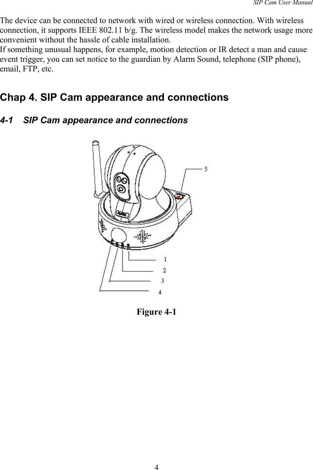
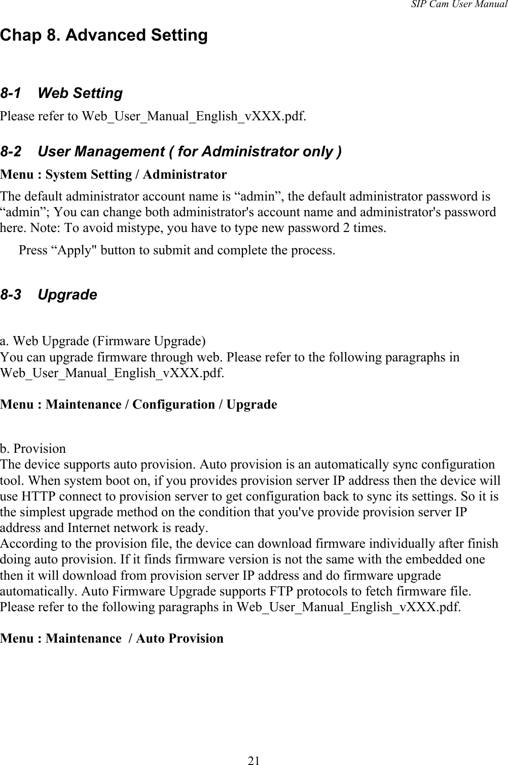
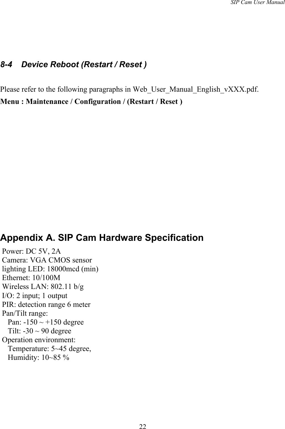
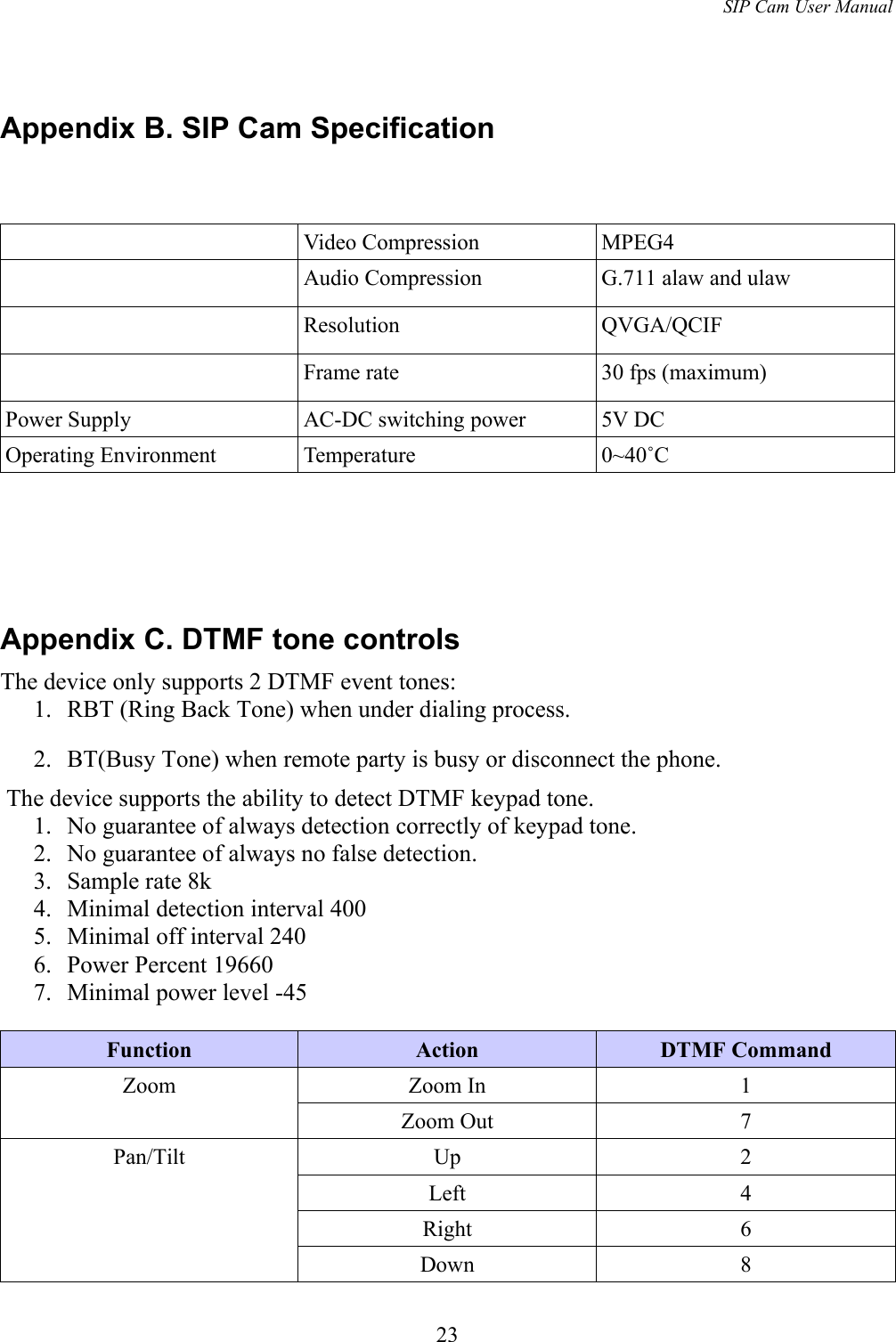
![SIP Cam User ManualMove to Home 5Upmost *20Up with step counts *2[1-8]Leftmost *40Left with step counts *4[1-9]Rightmost *60Right with step counts *6[1-9]Nethermost *80Down with step counts *8[1-8]Preset Register *7[1-4]Move to Preset *9[1-4]Camera High intensity LED ON *11High intensity LED OFF *10Microphone volume Up *1#Microphone volume Down *7#Speaker volume Up *3#Speaker volume Down *9#External Output ON *31OFF *3024Notice : The changes or modifications not expressly approved by the party responsible for compliance could void the user’s authority to operate the equipment.IMPORTANT NOTE: To comply with the FCC RF exposure compliance requirements, no change to the antenna or the device is permitted. Any change to the antenna or the device could result in the device exceeding the RF exposure requirements and void user’s authority to operate the device.The antenna used for this transmitter must be installed to provide a separation distance of at least 20cm from all persons and must not be co-located or operating in conjunction with any other antenna or transmitter.FCC INFORMATION•The Federal Communication Commission Radio Frequency InterferenceStatement includes the following paragraph:•The equipment has been tested and found to comply with the limits for a Class B Digital Device, pursuant to part 15 of the FCC Rules. These limits are designed to provide reasonable protection against harmful interference in a residential installation. This equipment generates, uses and can radiate radio frequencyenergy and, if not installed and used in accordance with the instruction, may cause harmful interference to radio communication. However, there is no grantee that interference will not occur in a particular installation. If this equipment dose cause harmful interference to radio or television reception, which can be determined by turning the equipment off and on , the user is encouraged to try to correct the interference by one or more of the following measures:--Reorient or relocate the receiving antenna.--Increase the separation between the equipment and receiver.--Connect the equipment into an outlet on a circuit different from that to which the receiver is connected.--Consult the dealer or an experienced radio/TV technician for help.The user should not modify or change this equipment without written approvalform Apexx Technology Corp. Modification could void authority to use this equipment.](https://usermanual.wiki/Apexx-Technology/APX-SIP1-02702/User-Guide-965810-Page-24.png)