Apexx Technology APX-SIP1-02702 SIP-CAM User Manual
Apexx Technology Corp. SIP-CAM
User manual

SIP Cam User Manual
SIP Cam
User Manual
Ver 1.0
1

SIP Cam User Manual
Table of Content
Chap 1. System requirements....................................................................3
Hardware.................................................................................................................................... 3
Network...................................................................................................................................... 3
Software requirements................................................................................................................3
Chap 2. Package Contents......................................................................... 3
Chap 3. Overview : SIP Cam function..................................................... 3
Chap 4. SIP Cam appearance and connections....................................... 4
4-1 SIP Cam appearance and connections...................................................................................4
4-2 LED Status............................................................................................................................ 6
4-3 Buttons in rear part of the device.......................................................................................... 6
Chap 5. Installation.................................................................................... 7
5-1 Hardware Installation............................................................................................................ 7
5-3 Wireless Installation..............................................................................................................8
Chap 6. Surveillance Setting......................................................................9
6-1 Time Setting (Time Zone).....................................................................................................9
6-2 Surveillance Setting (Event Triggers,PIR/Motion detection,GPIO)...................................10
6-3 Notification (Email, FTP)................................................................................................... 10
Chap 7. Call Setup....................................................................................10
7-1 Preparation.......................................................................................................................... 10
7-2 Making a call from softphone to the device........................................................................16
7-3 Making a call from the device to softphone........................................................................18
7-4 Incoming Call Restriction................................................................................................... 20
Chap 8. Advanced Setting........................................................................21
8-1 Web Setting.........................................................................................................................21
8-2 User Management ( for Administrator only )..................................................................... 21
8-3 Upgrade............................................................................................................................... 21
8-4 Device Reboot (Restart / Reset )......................................................................................... 22
Appendix A. SIP Cam Hardware Specification.................................... 22
Appendix B. SIP Cam Specification....................................................... 23
Appendix C. DTMF tone controls...........................................................23
2

SIP Cam User Manual
Chap 1. System requirements
Hardware
PC with Pentium III or above
RAM 256MB or above
Sound Card
Free hard disk space 100M or above
Network
Leased-line、xDSL or CABLE Modem
Upload speed 128 Kbps or more, 512 Kbps is recommended.
PS: For floating IP user, a Dynamic Domain Name Service (DDNS) is required. Please
refer to Appendix B for your reference.
Software requirements
Window XP service pack 2 or above.
Internet Explorer 6.0 SP1or above.
Chap 2. Package Contents
Chap 3. Overview : SIP Cam function
Tips : SIP Cam = Session Initiated Protocol Camera
PIR = Passive Infra Red
GPIO = General Purpose Input/Output
The main application of SIP Camera (it will be called as the device hereafter) is used in the
surveillance scope. It has built-in camera and a SIP phone.
It can be used to monitoring (guard safe in house), and the SIP phone can be used as
emergency call as a bidirectional telephone conversation.
There are 3 detection methods, they are : motion detect , PIR and GPIO (external sensor).
(you can use GPIO to connect to the other safety guard, such as door alarm system).
3
SIP Cam User Manual
The device can be connected to network with wired or wireless connection. With wireless
connection, it supports IEEE 802.11 b/g. The wireless model makes the network usage more
convenient without the hassle of cable installation.
If something unusual happens, for example, motion detection or IR detect a man and cause
event trigger, you can set notice to the guardian by Alarm Sound, telephone (SIP phone),
email, FTP, etc.
Chap 4. SIP Cam appearance and connections
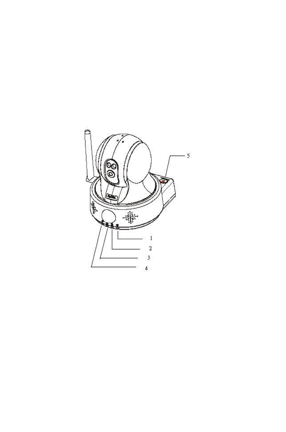
4-1 SIP Cam appearance and connections
Figure 4-1
4
SIP Cam User Manual
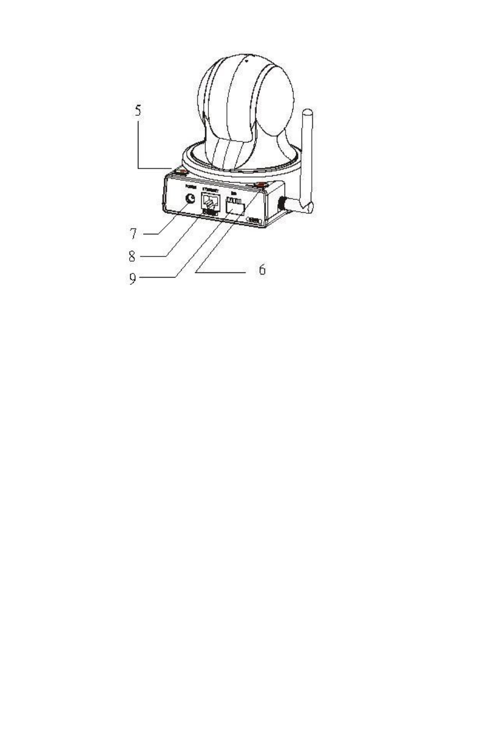
Figure 4-2
LED 1 : Power LED (Green)
LED 2 : Hardware Malfunction LED (Red)
LED 3 : Network LED (Green)
LED 4 : Monitor/Motion LED (Green)
button in position 5 : Dial / Hang up (phone call)
button in position 6 : lens parking
7 : power adaptor
8 : ethernet cable line
9 : GPIO
5

SIP Cam User Manual
4-2 LED Status
The device has 4 LEDs to indicate the status of the system.
Name Display
Status
System Status Remark
Power LED
(Green)
OFF Power Off
ON Power On
BLINKING System Booting/Reseting
Hardware
Malfunction LED
(Red)
OFF Hardware is workable
ON Hardware is malfunction
Network LED
(Green)
OFF System is not accessible
ON System is accessible DHCP client gets the IP
address or static IP is
assigned.
Monitor/Motion
LED (Green)
OFF Motion Detection is
disabled/No monitoring
through Web or SIP
ON Motion Detection is Enabled
or SIP Phone connected
BLINKING Under Web monitoring or SIP
monitoring
4-3 Buttons in rear part of the device
See Figure 4-2, button in position 5 : phone call, press once to dial phone or pick up the
phone, press it again to hang up. button in position 6 : lens parking, press this button, the
camera lens will go to the parking position. (lens down).
6
SIP Cam User Manual
Chap 5. Installation
5-1 Hardware Installation
Set up according to your network scenario.
5-1-1. Wired Network
A. Connect with ADSL / Cable Modem directly
B. Connect with ADSL / Cable Modem through NAT
5-1-2. Wireless Network
7
Sip cam ADSL / CABLE MODEM
Sip cam ADSL / CABLE MODEMNAT
1.DHCP
2.Intranet

SIP Cam User Manual
5-2 Network
*Tips : DHCP : Dynamic Host Configuration Protocol.
Menu : Network / Network
If local network has a DHCP server, DHCP server can dynamically give the device one
floating(Non-fixed) IP address, you can ask MIS administrator to acquire the detail.
When using DHCP mode, please set DHCP Status to "ON"; When using Fixed IP mode,
set DHCP Status to "OFF" and fill the fields in the fixed IP mode, including IP Address,
Subnet Mask, Gateway, Primary DNS, and Secondary DNS.
Press “Apply" button to submit and complete the process.
5-3 Wireless Installation
*Tips : WPS = Wi-Fi Protected Setup.
First thing you have to do is to find out the configuration of your wireless AP. There are
two methods of connecting the device to the AP. One is WPS method, the other is
traditional method (without WPS). The WPS method has two profiles: One is push button
method, the other is PIN code method. If your AP supports WPS push button method, it's
quickest method to setup. The traditional process (without WPS) is most complicated
process. See the following setup process for these 3 methods:
8
Sip cam ADSL / CABLE MODEM
Access Point
(AP)
1.DHCP
2.Intranet
3.PPPoE

SIP Cam User Manual
Traditional process (without
WPS)
Wi-Fi Protected Setup: PIN
code method
Wi-Fi Protected Setup: push
button method
1. Power on AP 1. Power on AP/registrar 1. Power on AP
2. Access AP
3. Set network name (SSID)
2. Power on SIP Cam. Network
name generated automatically
and broadcast to SIP Cam
2. Power on SIP Cam. Network
name generated automatically
and broadcast to SIP Cam
4. Activate security 3. Access registrar 3. Push button on AP
5. Set passphrase (see note1) 4. Enter PIN 4. Within 2 minutes, push
button on SIP Cam. (On back of
SIP Cam, the pinhole labeled
WPS)
6. Power on SIP Cam
7. Select network name (SSID)
8. Enter passphrase
If your AP doesn't support WPS, a traditional process is used. Assign one security protocol.
For example, after power on AP and access AP, assign WPA-PSK(TKIP) in Encryption
method of wireless AP. Assign a 8~63 ASCII characters as preshared key. Save and reboot
it. Then on the web site of the device, go to Network / Wireless; choose Enable to “On”;
fetch the value in ESSID field in wireless AP, and copy to ESSID field of the device.
Unplug the wired ethernet cable line, use search tool (for example, V750WConfig.exe) to
search the device, if you cannot find the device, go back to check the wireless settings again.
(note1) passphrase : A passphrase is a sequence of words used to control access to a
computer system, program or data. A passphrase is similar to a password in usage, but is
generally longer for added security. Passphrases are often used to control both access to, and
operation of, cryptographic programs and systems. Passphrases are particularly applicable to
systems that use the passphrase as an encryption key.
Menu : Network / Wireless
Chap 6. Surveillance Setting
6-1 Time Setting (Time Zone)
*Tips : NTP : Network Time Protocol.
OSD : On Screen Display.
9

SIP Cam User Manual
Menu : Maintenance / System / Time
You can get SIP Cam Time Zone from NTP Server or Local Computer time. When you
choose NTP Server, type in NTP Server name or use default NTP Server name :
ntp.nasa.gov ; you can just get SIP Cam Time Zone from local computer time by click “
Local Computer time” button. Time will be saved in the device, and will be showed upon
OSD if OSD require time to be showed.
We use "ntp.nasa.gov" as default NTP server.
You can get more information from http://www.ntp.org/
6-2 Surveillance Setting (Event Triggers,PIR/Motion detection,GPIO)
Please refer to the following paragraphs in Web_User_Manual_English_vXXX.pdf.
Menu : Surveillance / Event Trigger
Menu : Surveillance / Event Schedule
6-3 Notification (Email, FTP)
Please refer to the following paragraphs in Web_User_Manual_English_vXXX.pdf.
Menu : Surveillance / Event Trigger
Menu : Surveillance / Notification / Email
Menu : Surveillance / Notification / FTP
Chap 7. Call Setup
7-1 Preparation
Phone numbers must be registered to SIP Server before they can talk to each other. Now the
sip phone numbers are restricted to English alphabets and digits only. Ask SIP Server
manager to acquire the detail.
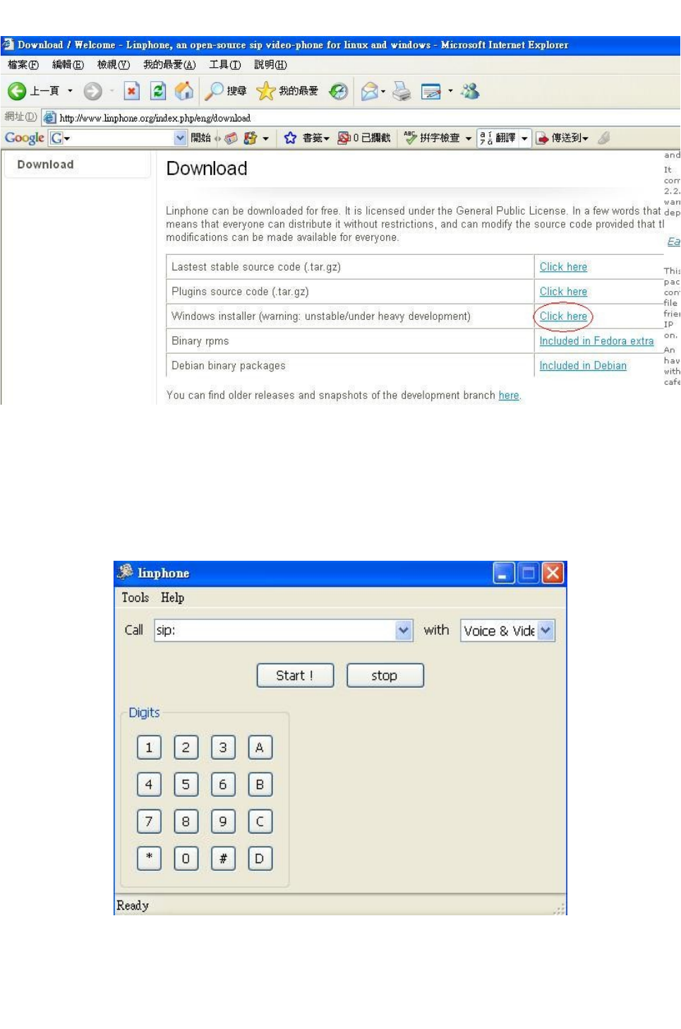
Now we have to download a program for softphone. We choose “linphone” as softphone.
Go to http://www.linphone.org/index.php/eng/download to download, for windows
installer.(circle in Figure 7-1, then choose linphone-win32-0.4.1-setup.exe).
10
SIP Cam User Manual
Figure 7-1
install linphone-win32-0.4.1-setup.exe . Other versions may be unstable.
After successfully installed, execute the program, the program looks like Figure 7-2.
Figure 7-2
11
SIP Cam User Manual
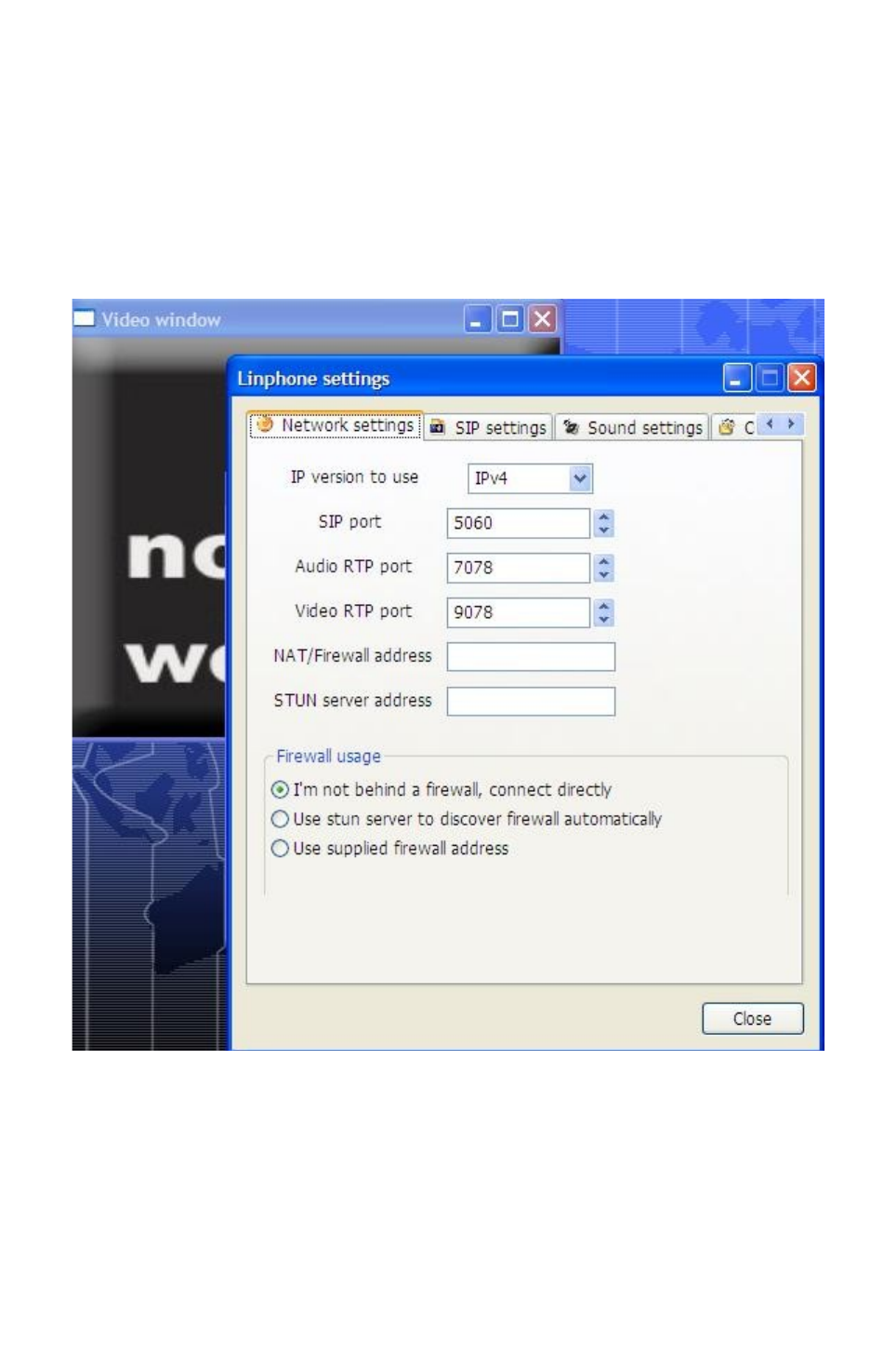
Click Tools / Settings, there are four tab setting pages,
a. Network settings
Choose your network settings according to your network scenario. Enter in the text box
your NAT/Firewall address if you choose “Use supplied firewall address”; Enter in the text
box your STUN server address if you choose “Use stun server to discover firewall
automatically”. Or you can choose “I'm not behind a firewall, connect directly”.
Figure 7-3
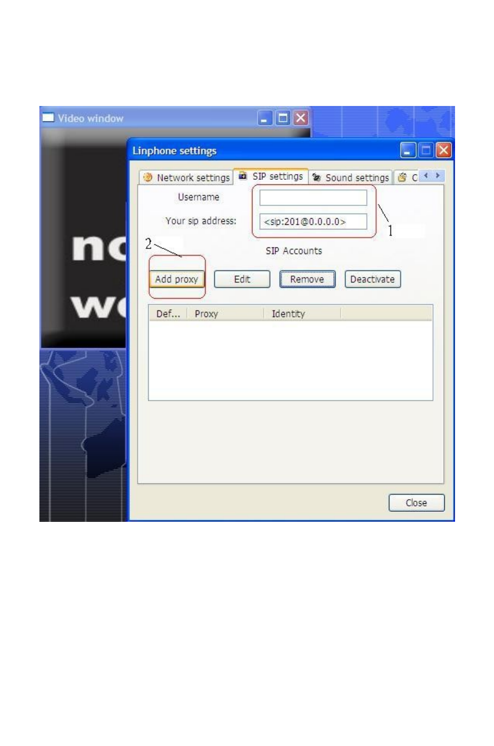
b.SIP settings
You can pay no attention to the “Username” and “Your sip address” text box. (1 in Figure
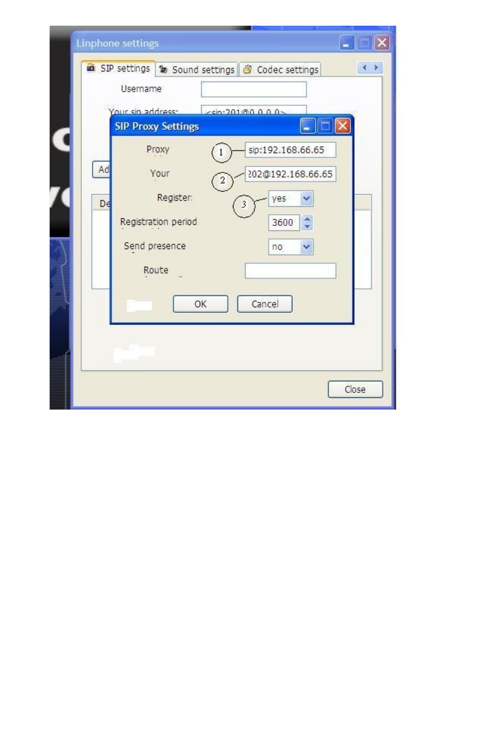
7-4). Press “Add proxy” button (2 in Figure 7-4), enter proxy server in the text box (1 in
Figure 7-5), (here we entered sip:192.168.66.65), enter your softphone SIP phone number
address in the text box (2 in Figure 7-5), (here we entered 202@192.168.66.65). Choose
“Register” to “yes”. Other parameters use default values, press “OK” button.
12
SIP Cam User Manual
For example, we want to make a call from softphone (SIP phone number :
202@192.168.66.65) to the device (SIP phone number : 201@192.168.66.65). Input as in
Figure 7-5.
Figure 7-4
13
SIP Cam User Manual
Figure 7-5
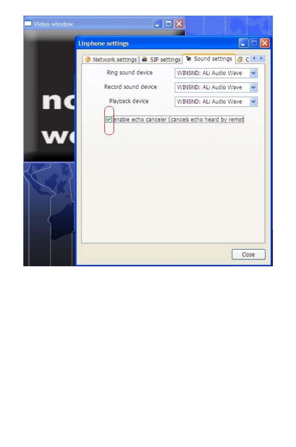
c.Sound settings
Check the checkbox “enable echo canceler”.
14
SIP Cam User Manual
Figure 7-6
d. Codec settings
You can do nothing here.
e. Finally, press “Close” button to finish the setting precess. (circle in Figure 7-7).
15
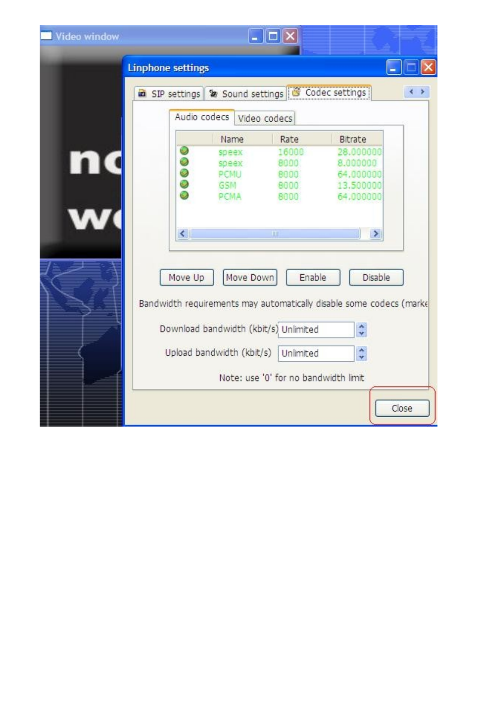
SIP Cam User Manual
Figure 7-7
7-2 Making a call from softphone to the device
After registration to SIP Server, you can test a call from softphone to the device in the LAN.
For example, a SIP Proxy server created as 192.168.66.65; we want to set the SIP phone
number of the device and softphone to 201@192.168.66.65 and 202@192.168.66.65
respectively.
(a). Set the SIP phone number of the device to 201@192.168.66.65
Menu : Phone / SIP
SIP Proxy : 192.168.66.65
Username : 201
Password : 201 (or anything else)
SIP Network Type : choose one of these according to your network scenario.
Press “Apply" button to submit and complete the process.
16

SIP Cam User Manual
(b). Set the SIP phone number of the softphone to 202@192.168.66.65
Menu : Phone / Outgoing Call
Phone Number : 202
Call Mode : Video Phone
Press “Apply" button to submit and complete the process.
(c). Reboot
Menu : Maintenance / Configuration / Restart Reset
To finish the above (a), (b) process, you have to reboot the device. Click “Restart” button to
reboot the device.
(d). Log Out
Menu : Log Out
Before you can use the softphone to talk to the people in the device side, you have to log
out.
(e). Final step
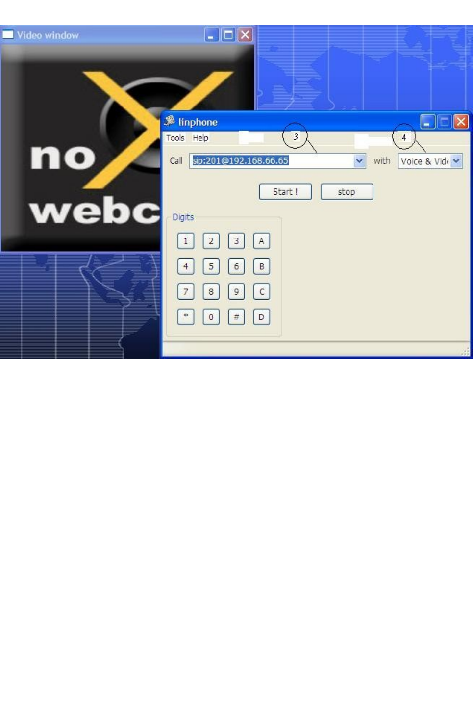
For example, we want to make a call from softphone (SIP phone number :
202@192.168.66.65) to the device (SIP phone number : 201@192.168.66.65). As you have
finished all steps in Chapter 7-1, the only thing you have to do here is enter the SIP phone
number you want to call ( text box 3 in Figure 7-7), choose “Voice & Video” in 4 (Figure 7-
8) if you want a call with voice & video simultaneously, after that, press “Start!” button in
the linphone panel. A ring tone should be heard on the SIP Cam side, after about 5 seconds
and ring tone changed from “DU-----------DU-----------”(longer time gap between two "DU"
sound) to “DU—DU—DU”(shorter time gap between two "DU" sound), press PIN code
designated in the Phone / Incoming call, after that, phone should be connected, so image on
the device side will appear, (through the camera lens) , you can talk with the man on the
device side (if any), check the quality of the voice and the video. After test is done, you can
press “stop” button in the linphone panel to end the phone.
17
SIP Cam User Manual
Figure 7-8
7-3 Making a call from the device to softphone
After registration to SIP Server, you can test a call from SIP Cam to softphone in the LAN.
For example, a SIP Proxy server created as 192.168.66.65; we want to set the SIP phone
number of the device and softphone to 201@192.168.66.65 and 202@192.168.66.65
respectively.
(a). Set the SIP phone number of the device to 201@192.168.66.65
Menu : Phone / SIP
SIP Proxy : 192.168.66.65
Username : 201
Password : 201 (or anything else)
18

SIP Cam User Manual
SIP Network Type : choose one of these according to your network scenario.
Press “Apply" button to submit and complete the process.
(b). Set the SIP phone number of the softphone to 202@192.168.66.65
Menu : Phone / Call / Outgoing Call
Phone Number : 202
Call Mode : Video Phone
Press “Apply" button to submit and complete the process.
(c). Reboot
Menu : Maintenance / Configuration / (Restart / Reset)
To finish the above (a), (b) process, you have to reboot the device. Choose “Reboot”
function to reboot the device.
(d). Log Out
Menu : Log Out
Before you can use the device to talk to the people in the softphone side, you have to log
out.
(e). Final step
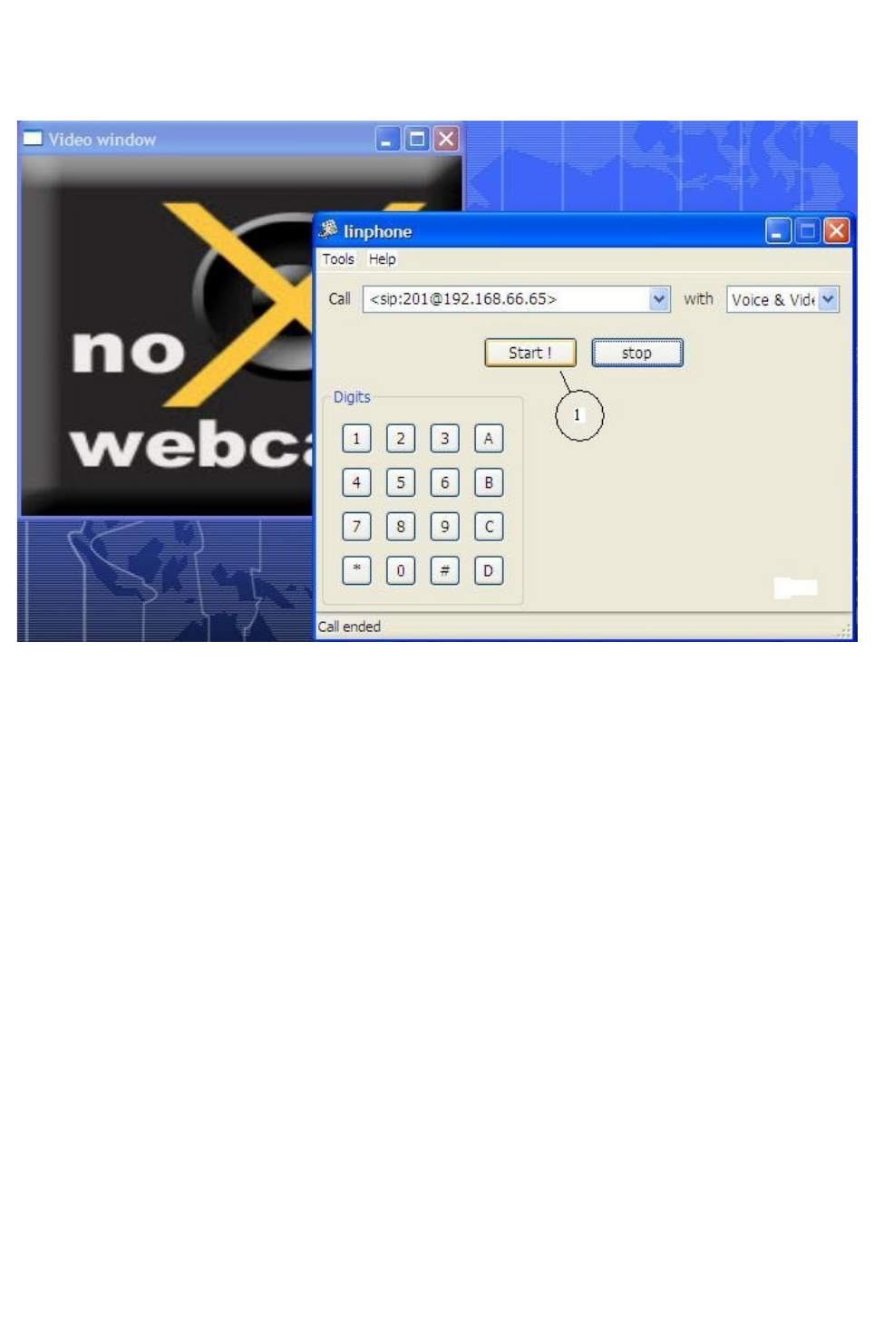
Press the “Phone Call” button (position 5 in Figure 4-2) to dial to softphone (PC/NB). A
ring tone should send out from speaker of PC/NB on the softphone side.
After the man in the softphone side press the “Start!” button in the linphone panel (1 in
Figure 7-9), phone is connected, so he can see the images (through the camera lens) and can
talk with the people on the device side (if any), check the quality of the voice and the video.
After test is done, press “stop” button in the linphone panel to end the phone.
19
SIP Cam User Manual
Figure 7-9
7-4 Incoming Call Restriction
You can restrict the incoming call to the device by the following way :
Menu : Phone / Incoming Call
Turn Restriction to “ON”, and fill in the phone number that can be accepted to the device. A
maximum of 16 phone numbers can be set. Don't forget to check the enable checkbox on
that column.
20

SIP Cam User Manual
Chap 8. Advanced Setting
8-1 Web Setting
Please refer to Web_User_Manual_English_vXXX.pdf.
8-2 User Management ( for Administrator only )
Menu : System Setting / Administrator
The default administrator account name is “admin”, the default administrator password is
“admin”; You can change both administrator's account name and administrator's password
here. Note: To avoid mistype, you have to type new password 2 times.
Press “Apply" button to submit and complete the process.
8-3 Upgrade
a. Web Upgrade (Firmware Upgrade)
You can upgrade firmware through web. Please refer to the following paragraphs in
Web_User_Manual_English_vXXX.pdf.
Menu : Maintenance / Configuration / Upgrade
b. Provision
The device supports auto provision. Auto provision is an automatically sync configuration
tool. When system boot on, if you provides provision server IP address then the device will
use HTTP connect to provision server to get configuration back to sync its settings. So it is
the simplest upgrade method on the condition that you've provide provision server IP
address and Internet network is ready.
According to the provision file, the device can download firmware individually after finish
doing auto provision. If it finds firmware version is not the same with the embedded one
then it will download from provision server IP address and do firmware upgrade
automatically. Auto Firmware Upgrade supports FTP protocols to fetch firmware file.
Please refer to the following paragraphs in Web_User_Manual_English_vXXX.pdf.
Menu : Maintenance / Auto Provision
21

SIP Cam User Manual
8-4 Device Reboot (Restart / Reset )
Please refer to the following paragraphs in Web_User_Manual_English_vXXX.pdf.
Menu : Maintenance / Configuration / (Restart / Reset )
Appendix A. SIP Cam Hardware Specification
Power: DC 5V, 2A
Camera: VGA CMOS sensor
lighting LED: 18000mcd (min)
Ethernet: 10/100M
Wireless LAN: 802.11 b/g
I/O: 2 input; 1 output
PIR: detection range 6 meter
Pan/Tilt range:
Pan: -150 ~ +150 degree
Tilt: -30 ~ 90 degree
Operation environment:
Temperature: 5~45 degree,
Humidity: 10~85 %
22

SIP Cam User Manual
Appendix B. SIP Cam Specification
Video Compression MPEG4
Audio Compression G.711 alaw and ulaw
Resolution QVGA/QCIF
Frame rate 30 fps (maximum)
Power Supply AC-DC switching power 5V DC
Operating Environment Temperature 0~40˚C
Appendix C. DTMF tone controls
The device only supports 2 DTMF event tones:
1. RBT (Ring Back Tone) when under dialing process.
2. BT(Busy Tone) when remote party is busy or disconnect the phone.
The device supports the ability to detect DTMF keypad tone.
1. No guarantee of always detection correctly of keypad tone.
2. No guarantee of always no false detection.
3. Sample rate 8k
4. Minimal detection interval 400
5. Minimal off interval 240
6. Power Percent 19660
7. Minimal power level -45
Function Action DTMF Command
Zoom Zoom In 1
Zoom Out 7
Pan/Tilt Up 2
Left 4
Right 6
Down 8
23

SIP Cam User Manual
Move to Home 5
Upmost *20
Up with step counts *2[1-8]
Leftmost *40
Left with step counts *4[1-9]
Rightmost *60
Right with step counts *6[1-9]
Nethermost *80
Down with step counts *8[1-8]
Preset Register *7[1-4]
Move to Preset *9[1-4]
Camera High intensity LED ON *11
High intensity LED OFF *10
Microphone volume Up *1#
Microphone volume Down *7#
Speaker volume Up *3#
Speaker volume Down *9#
External Output ON *31
OFF *30
24
Notice : The changes or modifications not expressly approved by the party responsible for compliance could void the
user’s authority to operate the equipment.
IMPORTANT NOTE: To comply with the FCC RF exposure compliance requirements, no change to the antenna or the
device is permitted. Any change to the antenna or the device could result in the device exceeding the RF exposure
requirements and void user’s authority to operate the device.The antenna used for this transmitter must be installed to
provide a separation distance of at least 20cm from all persons and must not be co-located or operating in conjunction
with any other antenna or transmitter.
FCC INFORMATION
•The Federal Communication Commission Radio Frequency Interference
Statement includes the following paragraph:
•The equipment has been tested and found to comply with the limits for a Class B Digital Device, pursuant to part 15 of the FCC Rules.
These limits are designed to provide reasonable protection against harmful interference in a residential installation. This equipment
generates, uses and can radiate radio frequency
energy and, if not installed and used in accordance with the instruction, may cause harmful interference to radio communication.
However, there is no grantee that interference will not occur in a particular installation. If this equipment dose cause harmful interference
to radio or television reception, which can be determined by turning the equipment off and on , the user is encouraged to try to correct
the interference by one or more of the following measures:
--Reorient or relocate the receiving antenna.
--Increase the separation between the equipment and receiver.
--Connect the equipment into an outlet on a circuit different from that to which the
receiver is connected.
--Consult the dealer or an experienced radio/TV technician for help.
The user should not modify or change this equipment without written approval
form Apexx Technology Corp. Modification could void authority to use this equipment.