Appareo Systems 1505005 Aircraft Transponder User Manual 600840 000031 Stratus ESG Installation Instructions TSO
Appareo Systems, LLC Aircraft Transponder 600840 000031 Stratus ESG Installation Instructions TSO
Contents
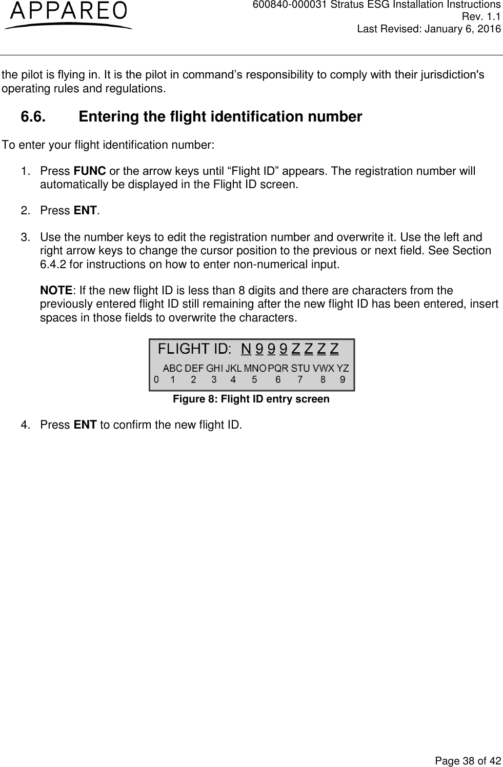
- 1. 600820-000015 Stratus ESG RF Emitter Notification Card
- 2. 600840-000031 Stratus ESG Installation Instructions (TSO)
600840-000031 Stratus ESG Installation Instructions (TSO)