Appareo Systems 1505005 Aircraft Transponder User Manual 600840 000031 Stratus ESG Installation Instructions TSO
Appareo Systems, LLC Aircraft Transponder 600840 000031 Stratus ESG Installation Instructions TSO
Contents
- 1. 600820-000015 Stratus ESG RF Emitter Notification Card
- 2. 600840-000031 Stratus ESG Installation Instructions (TSO)
600840-000031 Stratus ESG Installation Instructions (TSO)
This document and the information
contained herein are the property of
Appareo Systems, LLC and are
confidential. They may not be disseminated
or redistributed without the written
permission of Appareo Systems, LLC
APPAREO SYSTEMS, LLC
FARGO, NORTH DAKOTA 58102
Stratus ESG Installation Instructions
Document Number
600840-000031
Document Type
Certification
Last Revised
6 January 2016
Rev
1.1
Sheet
1 of 42
Installation Instructions
Revision 1.1

600840-000031 Stratus ESG Installation Instructions
Rev. 1.1
Last Revised: January 6, 2016
Page 2 of 42
STRATUS ESG
©2015-2016 Appareo Systems, LLC. All Rights Reserved.
Stratus ESG Installation Instructions. All content within is copyrighted by Appareo
Systems, LLC, and may not be reprinted without permission.
Appareo assumes no responsibility or liability for any errors or inaccuracies that may appear in
the information content contained in this guide. Unauthorized replication of this guide is
prohibited.
Appareo, Appareo Systems, Stratus ESG, and the Appareo and Stratus ESG logos are either
registered trademarks or trademarks of Appareo Systems, LLC. All other trademarks and
registered trademarks are the sole property of their respective owners.
Appareo Systems, LLC, 1830 NDSU Research Circle North, Fargo, ND 58102 USA.
Visit us on the web at www.appareo.com.
Questions? E-mail us at support@appareo.com.

600840-000031 Stratus ESG Installation Instructions
Rev. 1.1
Last Revised: January 6, 2016
Page 3 of 42
Stratus ESG Limited Warranty
When purchasing Stratus ESG (“Product”) manufactured by Appareo Systems, LLC
(“Appareo”), the original end user (“Initial Customer”) receives a limited warranty (Limited
Warranty) from Appareo. This Limited Warranty outlines the Initial Customer’s exclusive rights
and remedies as relates to the Product.
The Initial Customer receives an expressed limited warranty (referred to as the “Limited
Warranty”) for the Product purchased from Appareo. The terms of the Limited Warranty are
explained below. Additionally, State or Provincial law may adjust the terms of the Limited
Warranty, or the State or Province may impose additional obligations or additional “implied
warranties.” To the extent necessary to comply with those laws, the terms of the Limited
Warranty should be read to adjust to those requirements only to the extent necessary to comply
with such local law.
If you are the corporation or individual installing or using the Product, you are asked to read the
following terms and conditions carefully before installing or using this Product. By installing or
using the Product, you consent to be bound by and become a party to the Limited Warranty. If
you do not agree to the terms and conditions of the Limited Warranty, you should return the
Product for a full refund prior to installation.
PRODUCT LIMITED WARRANTY
Appareo warrants to you, the original Customer, that the Product will be free from defects in
material and workmanship for a period of time as indicated in the chart below from the Product
purchase date from Appareo or an authorized Appareo dealer, subject to the terms of this
Limited Warranty. Any Implied Warranty of Merchantability or for Fitness for a Particular
Purpose, if applicable to the Product, is limited in duration to the period of ownership by the
Initial Customer. This provision shall not create any Implied Warranty or Merchantability or of
Fitness for a Particular Purpose that would not otherwise apply to the Product.
Product Type
Warranty Period
For TSO Installed Stratus ESG
2 Years or 800 flight hours, whichever comes
first
For non-TSO Installed Stratus ESG
18 months from the date of purchase
For TSO Repaired or Newly Overhauled
Stratus ESG
6 Months or 200 flight hours, whichever
comes first
For non-TSO Repaired or Newly Overhauled
Stratus ESG
6 Months from the date of shipment from the
manufacturer
This Warranty is void if any part not supplied by Appareo is used in assembly or repair of the
Product, or if the Product has been altered.
EXCLUSIVE REMEDIES UNDER LIMITED WARRANTY
If the Product proves to be defective in material or workmanship during the Warranty Period,
and all Limited Warranty requirements have been met, your exclusive remedies, and Appareo’s
sole obligations, are that Appareo will repair or replace the Product under this Limited Warranty.

600840-000031 Stratus ESG Installation Instructions
Rev. 1.1
Last Revised: January 6, 2016
Page 4 of 42
MAKING A LIMITED WARRANTY CLAIM
To make a Limited Warranty claim on your Product, you must do the following:
1. Call Appareo at (701) 356-2200, write to Appareo at 1830 NDSU Research Circle North,
Fargo, ND 58102, or e-mail Appareo at support@appareo.com and provide the Product’s serial
number and date of purchase.
2. Provide reasonable proof of purchase (for example, a sales receipt) that establishes you
as the Initial Customer (the original end-user consumer purchaser) and which provides evidence
that the Product was purchased within the warranty period of the event for which you are
making a claim for warranty service.
3. Appareo will provide you with a Return Materials Authorization number and shipping
information for the return of your unit.
4. Upon receipt of the returned Product, Appareo will inspect it and make a determination
as to validity of the warranty claim. Appareo will respond to you within 15 days of receipt of the
Product.
5. If upon examination it is determined that the Product is operating within factory
recommended specifications, you will be notified and may request that the Product be returned
to you. You will be asked to pay a reasonable service charge and also for shipping expenses to
and from Appareo.
6. If it is determined upon examination that the Product is not operating within factory
recommended specifications, but that the source of the failure was outside of the scope of this
Limited Warranty, you will be notified of the estimated cost for repair of the Product to factory
specifications. At this time you may request that the Product be returned to you without further
action or that Appareo repair the Product as per the provided estimate and return the product to
you. In this case you will be billed for the repairs and for shipping expenses to and from
Appareo.
7. If it is determined that the returned Product fall within the scope of this Limited Warranty,
Appareo will repair or replace the Product at its discretion. Replacement Product may be new or
factory refurbished at Appareo’s discretion, and shall carry the warranty of the original Product.
Following repair or replacement, Product shall be shipped to the same location in the same
manner as was the returned Product. Appareo shall pay all associated shipping expenses.
THE LIMITED WARRANTY DOES NOT APPLY UNLESS THE INITIAL CUSTOMER:
1. Has properly operated the Product.
2. Has installed and maintained the Product properly per any installation or maintenance
instructions provided.

600840-000031 Stratus ESG Installation Instructions
Rev. 1.1
Last Revised: January 6, 2016
Page 5 of 42
APPAREO DOES NOT COVER OR UNDERTAKE ANY LIABILITY IN ANY EVENT FOR ANY
OF THE FOLLOWING:
1. Loss of or damage to data, records, or software or the restoration of data or records, or
the reinstallation of software.
2. Damage from any circumstance described as excluded below with respect to the
product.
3. Damages from fire, flood, wind, rain, rising water, leakage or breakage of plumbing,
abuse, misuse or alteration of the product.
NO DEALER WARRANTY
This is the exclusive warranty applicable to Appareo Products. No dealer has any authority to
make any other warranty, modify, limit, or expand the terms of this Warranty in any fashion, or
to make any representation or promise on behalf of Appareo.
EXCLUSION OF CONSEQUENTIAL AND OTHER DAMAGES
1. The sole and exclusive remedies of the Initial Customer are those provided by the
Limited Warranty. Appareo excludes any liability for personal injury under the Limited Warranty.
Appareo excludes any liability for direct, indirect, special, incidental or consequential damages,
whether for damage to or loss of property, loss of profits, business interruption, or loss of
information or data.
2. Danger: Do not use for medical or life support equipment or other high risk activities!
3. Appareo does not sell their Products for use in high-risk activities. The Product is not
designed or intended for use in hazardous environments requiring fail-safe performance or for
use in any circumstance in which the failure of the Product could lead directly to death, personal
injury, or severe physical or property damage, or that would affect operation or safety of any
medical or life support device (collectively “High Risk Activities”). Appareo expressly disclaims
any express or implied warranty of fitness for High Risk Activities. Appareo does not authorize
use of any of the Products in any High Risk Activities.
4. This Limited Warranty is governed by the laws of the United States and the State of
North Dakota, without reference to conflict of law principles.
5. Contact Information: Appareo’s address is 1830 NDSU Research Circle North, Fargo,
ND 58102. Their phone number is (701) 356-2200. Appareo is the warrantor under this Limited
Warranty. You may also contact Appareo on the Internet at www.appareo.com
6. CAUTION: Any changes or modifications not expressly approved by the warranty and/or
user documentation accompanying this device could void the user’s authority to operate the
equipment.

600840-000031 Stratus ESG Installation Instructions
Rev. 1.1
Last Revised: January 6, 2016
Page 6 of 42
EXPORT REGULATIONS
Certain Appareo products are subject to export controls by the U.S. Department of Commerce
(DOC), under the Export Administration Regulations (EAR). Violation of U.S. law is strictly
prohibited. You agree to comply with the requirements of the EAR and all applicable
international, national, state, regional and local laws, and regulations, including any applicable
import and use restrictions.
For further information or clarification regarding these regulations please contact Appareo.

600840-000031 Stratus ESG Installation Instructions
Rev. 1.1
Last Revised: January 6, 2016
Page 7 of 42
Warnings
The pilot must read the Stratus ESG Pilot’s Guide (600890-000049) before their first
flight.
Squawk codes 7500 (hijacking), 7600 (radio failure), and 7700 (emergency) are
reserved for emergencies. There may be other reserved codes, depending on the region
you are flying in. It is the pilot in command’s responsibility to comply with their
jurisdiction's operating rules and regulations.

600840-000031 Stratus ESG Installation Instructions
Rev. 1.1
Last Revised: January 6, 2016
Page 8 of 42
Record of Revision
Revision
Number
Change Description
Revision Date
Inserted By
1.0
Initial Release
5/29/15
AAL
1.1
Incorporated mechanical changes to
Stratus ESG
1/06/16
AAL
Related Documentation
Document Number
Title
600845-000024
Stratus ESG Instructions for Continued Airworthiness
600890-000049
Stratus ESG Pilot’s Guide
601837-000024
Stratus ESG Installation and Wiring Drawings

600840-000031 Stratus ESG Installation Instructions
Rev. 1.1
Last Revised: January 6, 2016
Page 9 of 42
Abbreviations, Terms, and Definitions
Abbreviation
Term
Definition
ADS-B
Automatic
Dependent
Surveillance -
Broadcast
Technology implemented by the FAA to provide
surveillance and improved situational awareness to both
pilots and air traffic controllers.
ATC
Air Traffic
Control
Service that directs aircraft on the ground and through
controlled airspace.
CFR
Code of Federal
Regulations
Codification of the general and permanent rules and
regulations published in the Federal Register by the
executive departments and agencies of the United States
Federal government.
FAA
Federal Aviation
Administration
Agency of the United States Department of Transportation
with authority to regulate and oversee all aspects of civil
aviation in the United States.
GPS
Global
Positioning
System
Satellite-based navigation system that provides location
and time information.
Hz
Hertz
Unit of frequency based upon cycles per second.
IDENT
IDENT
(Identification)
Transponder feature that allows for aircraft to be uniquely
identified by Air Traffic Control by pulsing the aircraft’s
reply on ATC’s monitors for 18 seconds.
TSO
Technical
Standard Order
Minimum performance standard for specified materials,
parts, and appliances used on civil aircraft (FAA
definition).
VFR
Visual Flight
Rules
A set of regulations for flying in which the pilot flies without
using instruments in generally clear meteorological
conditions
WAAS
Wide Area
Augmentation
System
System of ground-based antennas whose precisely known
locations are used to correct satellite signals and provide
greater positional and integrity of service to aircraft in
flight.

600840-000031 Stratus ESG Installation Instructions
Rev. 1.1
Last Revised: January 6, 2016
Page 10 of 42
Table of Contents
1. About Stratus ESG ..............................................................................................................13
1.1. Overview .................................................................................................................13
1.2. TSO/FCC compliance ..............................................................................................13
1.3. TSO deviations ........................................................................................................13
1.4. Non-TSO functions ..................................................................................................13
1.5. Environmental qualifications ....................................................................................14
1.6. Criticality level .........................................................................................................14
1.7. Current software ......................................................................................................14
1.8. Equipment specifications .........................................................................................15
1.9. Required tools .........................................................................................................16
1.10. Required hardware ..................................................................................................16
1.11. Compatible equipment .............................................................................................17
2. Installing Stratus ESG .........................................................................................................19
2.1. Unpacking/inspection requirements .........................................................................19
2.2. Limitations for installation ........................................................................................19
2.3. Backplate assembly and rack installation ................................................................19
2.4. Unit installation ........................................................................................................20
2.5. Cleaning ..................................................................................................................20
2.6. Placard installation ..................................................................................................20
3. Cabling and wiring ...............................................................................................................20
3.1. Cabling and wiring specifications .............................................................................20
3.2. Pins .........................................................................................................................21
3.3. Connecting antennas...............................................................................................24
4. Configuring Stratus ESG .....................................................................................................24
4.1. ICAO address ..........................................................................................................25
4.2. VFR squawk ............................................................................................................25
4.3. Aircraft registration ..................................................................................................25
4.4. Aircraft airspeed category ........................................................................................25
4.5. Aircraft category ......................................................................................................25
4.6. Aircraft length ..........................................................................................................25
4.7. Aircraft width ...........................................................................................................26
4.8. Altitude format .........................................................................................................26
4.9. Squat switch ............................................................................................................26
4.10. Altitude source.........................................................................................................26
4.11. Backlight source ......................................................................................................26
4.12. Backlight slope ........................................................................................................26
4.13. Backlight offset ........................................................................................................26

600840-000031 Stratus ESG Installation Instructions
Rev. 1.1
Last Revised: January 6, 2016
Page 11 of 42
4.14. Backlight response time ..........................................................................................27
4.15. GPS antenna lateral offset ......................................................................................27
4.16. GPS antenna longitudinal offset ..............................................................................27
4.17. ADS-B In capability .................................................................................................27
4.18. SBAS service provider .............................................................................................28
4.19. Diagnostic screens ..................................................................................................28
5. Functional tests ...................................................................................................................30
5.1. Power bus ...............................................................................................................30
5.2. Discrete inputs.........................................................................................................30
5.3. Analog inputs ..........................................................................................................31
5.4. Altitude ....................................................................................................................32
5.5. EMI check ...............................................................................................................32
5.6. Compass swing test ................................................................................................34
5.7. Flight test .................................................................................................................34
6. Using Stratus ESG ..............................................................................................................34
6.1. Mode selection keys ................................................................................................35
6.2. Event indicators .......................................................................................................35
6.3. FUNC key ................................................................................................................36
6.4. Other keys ...............................................................................................................37
6.5. Entering a squawk code ..........................................................................................37
6.6. Entering the flight identification number ...................................................................38
Technical Assistance ................................................................................................................39
Appendix A ...............................................................................................................................40

600840-000031 Stratus ESG Installation Instructions
Rev. 1.1
Last Revised: January 6, 2016
Page 12 of 42
List of Figures
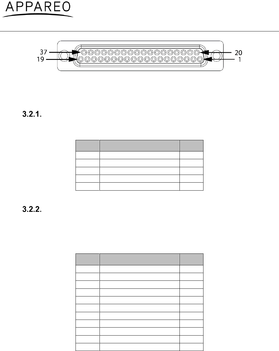
Figure 1: Pin-out .......................................................................................................................22
Figure 2: Ambient light sensor location .....................................................................................31
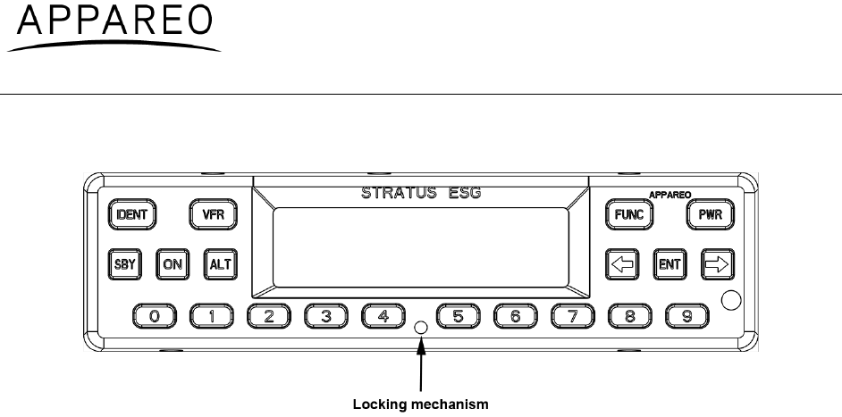
Figure 3: Stratus ESG front panel .............................................................................................35
Figure 4: Pressure altitude screen.............................................................................................36
Figure 5: GPS screen ................................................................................................................36
Figure 6: Flight ID screen ..........................................................................................................36
Figure 7: Brightness screen ......................................................................................................36
Figure 8: Flight ID entry screen .................................................................................................38
List of Tables
Table 1: TSO/FCC compliance .................................................................................................13
Table 2: TSO deviations ............................................................................................................13
Table 3: Criticality level .............................................................................................................14
Table 4: Current software ..........................................................................................................14
Table 5: Equipment dimensions ................................................................................................15
Table 6: Equipment weight ........................................................................................................15
Table 7: Electrical specifications ...............................................................................................15
Table 8: Power requirements ....................................................................................................16
Table 9: Required tools .............................................................................................................16
Table 10: Required hardware (supplied parts) ..........................................................................16
Table 11: Required hardware (additional parts).........................................................................17
Table 12: Compatible GPS antenna ..........................................................................................17
Table 13: Compatible transponder antenna ..............................................................................18
Table 14: Pin assignments ........................................................................................................21
Table 15: Power pin assignments .............................................................................................22
Table 16: Parallel altitude encoder pin assignments .................................................................22
Table 17: Serial altitude encoder pin assignments ....................................................................23
Table 18: Suppression pin assignments ....................................................................................23
Table 19: Aircraft lighting bus pin assignments .........................................................................23
Table 20: External IDENT pin assignment .................................................................................23
Table 21: External standby pin assignment ...............................................................................24
Table 22: Squat switch pin assignment .....................................................................................24
Table 23: Keys used during configuration .................................................................................25
Table 24: BIT diagnostic codes .................................................................................................30
Table 25: Mode selection keys ..................................................................................................35
Table 26: Event indicators .........................................................................................................36

600840-000031 Stratus ESG Installation Instructions
Rev. 1.1
Last Revised: January 6, 2016
Page 13 of 42
1. About Stratus ESG
1.1. Overview
Stratus ESG by Appareo is a panel-mounted level 2els Class 1 Extended Squitter transponder.
It is a Class B1S transponder which is ADS-B Out compliant. To support the ADS-B Out
function, Stratus ESG contains a Class Beta 1 GPS/WAAS receiver. Stratus ESG responds to
legacy Mode A/C interrogations and Mode S interrogations from both ground radar and airborne
collision avoidance systems.
This document and other Stratus ESG documentation can be found at the Appareo Dealer
Portal at http://appareo.com/dealer-portal.
1.2. TSO/FCC compliance
TSO
Stratus ESG is compliant with the following Technical Standard Orders:
Reference/Issue
Title
FAA TSO-C112e
Technical Standard Order: Air Traffic Control Radar Beacon
System/Mode Select (ATCRBS / Mode S) Airborne Equipment
FAA TSO-C145d
Technical Standard Order: Airborne Navigation Sensors Using The
Global Positioning System
FAA TSO-C166b
Technical Standard Order: Extended Squitter Automatic Dependent
Surveillance - Broadcast (ADS-B) and Traffic Information Service -
Broadcast (TIS-B) Equipment Operating on the Radio Frequency of
1090 Megahertz (MHz)
Table 1: TSO/FCC compliance
FCC
Stratus ESG has an FCC ID of 2AETC-1505005.
1.3. TSO deviations
TSO
Section
Deviation
TSO-C145d
Section 3, Subpart D
Environmental qualification testing was
performed to DO-160G, not DO-160E.
TSO-C166b
Section 5, Paragraph L
Environmental qualification testing was
performed to DO-160G, not DO-160F.
Table 2: TSO deviations
1.4. Non-TSO functions
Below are Stratus ESG’s non-TSO functions:
VFR key (and configuration).

600840-000031 Stratus ESG Installation Instructions
Rev. 1.1
Last Revised: January 6, 2016
Page 14 of 42
This non-TSO function does not interfere with Stratus ESG’s compliance with the requirements
of the TSOs listed in Section 1.2
1.5. Environmental qualifications
Stratus ESG is tested to DO-160G. The Stratus ESG Environmental Qualification form is found
in Appendix A of this document.
1.6. Criticality level
Software level determination is based on the Functional Hazard Assessment (FHA) and
Preliminary System Safety Assessment (PSSA). These assessments determined that the most
severe failure conditions (see Table 3) are classified as Major. As such, the Software Assurance
Level has been determined to be Major.
Major failure conditions would reduce the capability of the aircraft or the ability of the crew to
cope with adverse operating conditions to the extent that it would be a significant reduction in
safety margins or functional capabilities or a significant increase in crew workload. Software
whose anomalous behavior would cause or contribute to a failure of the system function
resulting in a Major failure condition for the aircraft is identified as Level C.
Function
Description
Classification
ATCRBS / Mode S
Transponder
Malfunction of the ATCRBS / Mode S
transponder function without warning
Major
ADS-B Out
Broadcast of incorrect ADS-B messages
without warning
Major
GPS/SBAS Receiver
Loss or malfunction of the GPS/SBAS receiver
function
Major
Pressure Altitude Output
Failure of the pressure altitude output function
Major
RF Feed-Through
Malfunction of the RF feed-through function
without warning
Major
Table 3: Criticality level
1.7. Current software
Part number
Revision
Version
501010-000109
R00
1.1.0.153
501010-000113
R00
1.1.0.523
Table 4: Current software

600840-000031 Stratus ESG Installation Instructions
Rev. 1.1
Last Revised: January 6, 2016
Page 15 of 42
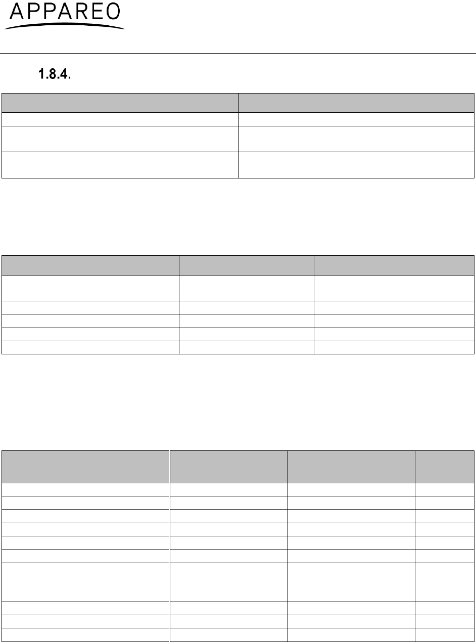
1.8. Equipment specifications
Equipment dimensions
Characteristic
Dimension
Bezel Width
6.38 inches (162 mm)
Bezel Height
1.69 inches (43 mm)
Rack Width
6.32 inches (160.4 mm)
Rack Height
1.65 inches (42 mm)
Depth from back of bezel to end of strain
relief on rack (not compensating for wire
bend radius)
10.75 inches (273 mm)
Table 5: Equipment dimensions
Equipment weight
Component
Weight
Stratus ESG Unit Weight
2.75 lbs. (1.25 kg)
Stratus ESG Total Installed Weight
(Transponder with rack and connectors)
3.29 lbs. (1.49 kg)
Table 6: Equipment weight
Electrical specifications
Characteristic
Specification
Altitude
Up to 25,000 ft
External Suppression Input
Low ≤ 0.5 V
High ≥ 5 V (suppressed)
Mode A Capability
4096 Identification Codes
Mode C Altitude Capability
Parallel altitude encoder: up to 62,700 ft
Serial altitude encoder: up to 126,700 ft
Mode S Capability
Parallel altitude encoder: up to 62,700 ft
Serial altitude encoder: up to 126,700 ft
Operational Temperature Range
-20°C to +55°C
Receiver Frequency
1030 MHz
Receiver Sensitivity
-74 dBm nominal for 90% replies
Transmitter Frequency
1090 MHz ± 1 MHz
Transmitter Power
310 Watts nominal
Table 7: Electrical specifications
600840-000031 Stratus ESG Installation Instructions
Rev. 1.1
Last Revised: January 6, 2016
Page 16 of 42
Power requirements
Characteristic
Specification
Input Voltage Range
11 to 36 VDC
Nominal Current Draw
0.28 A at 28 VDC
0.5 A at 14 VDC
Power Input
8 W Typical
59.5 W Max
Table 8: Power requirements
1.9. Required tools
The following tools are needed for installation of Stratus ESG.
Tool
Part Number
Used For
3/32” hex driver
Securing locking mechanism
through the faceplate
External retaining ring pliers
RF pass through adapter
Crimp tool
M22520/2-01
DSUB pins
Positioner
M22520/2-08
DSUB pins
Insertion/Extraction tool
M81969/39-01
DSUB pins
Table 9: Required tools
1.10. Required hardware
The following parts are required for the installation of Stratus ESG.
Supplied parts:
Item
Appareo Part
Number
Commercial Part
Number
Quantity
Backplate Assembly
153510-000015
-
1
Transponder
153510-000017
-
1
Stratus ESG Rack
153540-000027
-
1
RF TNC Pass Through Adapter
251015-000077
-
1
RF BNC Pass Through Adapter
251015-000078
-
1
37 Pin DSUB Connector
251015-000074
M24308/4-4F
1
GPS Antenna
252005-000007
42G15A-XT-1, or other
approved antenna (see
Section 1.11.1.1.)
1
Screw
356060-000007
4C25MTP3/NPA
6
Retaining Ring
356060-000024
98410A119
2
Strain Relief Backshell
356070-000006
M85049/48-1-4F
1
Table 10: Required hardware (supplied parts)
600840-000031 Stratus ESG Installation Instructions
Rev. 1.1
Last Revised: January 6, 2016
Page 17 of 42
Additional parts:
Item
Appareo Part
Number
Commercial Part
Number
Quantity
#6-32 Self-Locking Nut
-
MS21042 or other
approved fastener
6
#6-32 x 100° Flat Head SS
Screw
-
MS24693, AN507R or
other approved
fastener
6
Table 11: Required hardware (additional parts)
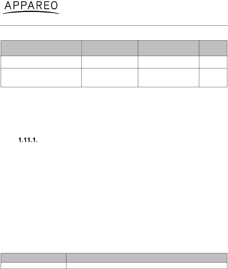
1.11. Compatible equipment
Stratus ESG requires input from a GPS antenna, transponder antenna, and altitude encoder.
This section describes the requirements for the antennas and altitude encoders that must be
installed on the aircraft.
Antennas
The GPS and transponder antennas should be installed using the antenna manufacturer’s
instructions. Wiring must be installed in accordance with FAA AC 43.13-1B and AC 43.13-2B.
1.11.1.1. GPS antenna
Stratus ESG requires an active antenna with the specifications of either TSO-C190 or
TSO-C144.
If meeting the specifications of TSO-C190, the GPS antenna must meet the following:
Powered at 5 Volts
Gain of 30 dB +- 5 dB
Qualified DO-160E Lightning, Zone 2A
Qualified DO-160E Icing, Category C
Alternatively, the following TSO-C144 antenna is compatible:
Manufacturer
Part Number
AntCom
42G15A-XT-1
Table 12: Compatible GPS antenna
The antenna should be installed using the antenna manufacturer’s instructions. The antenna
must also be installed at least 2 feet away from any other comm transmitter or transmitter
antenna in a location that does not break line of sight with satellites. Typical installation
locations are on the top of the aircraft or on the empennage with consideration for line of sight
with satellites.
All wiring should have a minimum of 3 dB loss and a maximum of 7 dB loss. Each BNC or TNC
connection is estimated to have a 0.2 dB loss.
600840-000031 Stratus ESG Installation Instructions
Rev. 1.1
Last Revised: January 6, 2016
Page 18 of 42
NOTE: Using RG400 the minimum cable length is 9 feet. The maximum length of RG400 is 37
feet. If the installation requires more or less length, select other 50 ohm coax.
If installing on a pressurized aircraft, follow the instructions as indicated by an aircraft STC.
Otherwise, seek other approval. Other provisions could be made by contacting your Regional
Aircraft Certification Office (ACO).
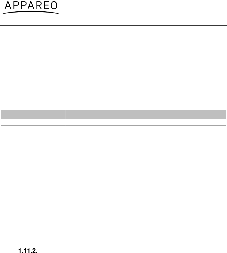
1.11.1.2. Transponder antenna
Stratus ESG requires a passive antenna with the specifications of TSO-C74d or TSO-C66. The
following antenna is an example of an antenna that meets these specifications. The installation
is not limited to this antenna.
Manufacturer
Part Number
Rami
AV-74
Table 13: Compatible transponder antenna
The antenna should be installed using the antenna manufacturer’s instructions. The antenna
should be mounted vertically on the bottom of the aircraft and a minimum of:
6 feet away from DME antenna
3 feet away from ADF antenna or any other communication antenna
3 feet away from TCAS antenna
3 feet away from Stratus ESG itself to prevent self-interference
Keep the antenna away from any protruding metal such as engines, propellers, other antenna
masts, landing gear (and/or doors), and access doors; breaks in the antenna's ground plane; or
anything that can affect the radiation pattern. If mounted on a composite aircraft, a conductive
ground plane should be added to the aircraft in order for the radiation pattern of the antenna to
be maximized.
NOTE: A determination should be made whether the current cabling is acceptable for the
installation. Using RG400, the maximum cable length is 14 feet with a maximum of 2 dB loss. If
the installation requires more length, select other 50 ohm coax.
Altitude encoders
Stratus ESG requires input from an independent altitude encoder. Stratus ESG will connect to
an encoder that has a Gillham (gray code) connection or a serial altitude encoder output on a
RS232 port. The altitude encoder must meet the performance requirements of TSO-C88 (a
or b). Serial altitude encoders must be Trimble/Garmin or Shadin/RMS altitude encoders.
The altitude encoder should be installed using the altitude encoder manufacturer’s instructions.
NOTE: The altitude encoder might have a longer power up time than Stratus ESG. While the
altitude encoder powers up, the altitude field will be replaced by dashes. If the altitude encoder
has not powered up within five minutes, an error message will appear. Once the attitude
encoder is completely powered on and transmitting data, the error message will disappear.

600840-000031 Stratus ESG Installation Instructions
Rev. 1.1
Last Revised: January 6, 2016
Page 19 of 42
2. Installing Stratus ESG
2.1. Unpacking/inspection requirements
When unpacking Stratus ESG, visually inspect for any damage to the unit or missing
components. If damage or missing parts are present, contact Appareo.
2.2. Limitations for installation
This article meets the minimum performance and quality control standards required by a
technical standard order (TSO). If you are installing this article on or in a specific type or class of
aircraft, you must obtain separate approval for installation.
The following limitations should be taken into consideration when installing Stratus ESG.
Aircraft
Stratus ESG may not be acceptable for installation on all aircraft makes and models.
Cooling air
Stratus ESG does not have an air cooling duct. Do not install Stratus ESG near a heat source.
An alternate method of cooling is required if the unit must be installed near a heat source.
2.3. Backplate assembly and rack installation
Refer to Stratus ESG Installation and Wiring Drawings (601837-000024) to assemble the
mounting rack with the hardware specified in Table 10. Mount the rack to the aircraft using the
six holes on the side of the rack with the hardware specified in Table 11.
Refer to Section 1.8 for dimensions and weight information.
NOTE: For an optimal fit, mounting brackets may be required, but are not supplied. If additional
brackets are needed, they should be fabricated for each individual installation.
NOTE: Assure that the unit is supported in the back. This may require additional support.
600840-000031 Stratus ESG Installation Instructions
Rev. 1.1
Last Revised: January 6, 2016
Page 20 of 42
2.4. Unit installation
1. Adjust the locking mechanism on Stratus ESG using a 3/32 hex wrench so that
the front lobe is in a vertical position. Insert the unit into the mounting rack until
the faceplate is flush with the front end of the rack.
2. Tighten the locking mechanism clockwise with the 3/32 hex wrench until it is tight
and the connectors have mated. Do not overtighten. If the mechanism will not
tighten, verify that Stratus ESG is properly seated in the rack.
2.5. Cleaning
Use a dry cloth to clean Stratus ESG. If necessary, a lightly damp cloth with a solution of mild
detergent can be used. Do not use cleaners containing ammonia, acetone, or other strong acids
or bases to clean the Stratus ESG display or faceplate.
2.6. Placard installation
Placards should be installed in accordance with AC 43.13-2B, Chapter 2, Section 207, Sub-
Section f., Paragraph (4).
3. Cabling and wiring
This section describes cabling and wiring specifications, pin-out information, and antenna
connection procedures.
CAUTION: Stratus ESG must be OFF during wiring to avoid damaging the device.
3.1. Cabling and wiring specifications
Wiring must be installed in accordance with FAA AC 43.13-1B and AC 43.13-2B and will be
supplied by the aircraft installer. Wiring will be 20-24 gauge; see Stratus ESG Installation and
Wiring Drawings (601837-000024) for exact specifications. The wire length and routing will vary
by installation.

600840-000031 Stratus ESG Installation Instructions
Rev. 1.1
Last Revised: January 6, 2016
Page 21 of 42
3.2. Pins
The following are the pin assignments and pin-out for Stratus ESG.
Pin #
Pin Name
I/O
1
Aircraft Ground
-
2
Aircraft Power
-
3
RS232-RX Maintenance
In
4
-
-
5
RS232-RX Altitude
In
6
RS232-TX GPS 1PPS
Out
7
External Standby
In
8
Software Update Enable
In
9
Altitude A1
In
10
Altitude A4
In
11
Altitude B2
In
12
Altitude C1
In
13
Altitude C4
In
14
External Suppress In
In
15
28V Lighting Bus HI
In
16
-
-
17
AUX +5V Power
Out
18
AUX Ground
-
19
AUX +5V Power
Out
20
Aircraft Ground
-
21
Aircraft Power
-
22
RS232-TX Maintenance
Out
23
RS232-TX AUX
Out
24
RS232-TX Altitude
Out
25
External IDENT
In
26
External Squat Switch
In
27
Altitude D4
In
28
Altitude A2
In
29
Altitude B1
In
30
Altitude B4
In
31
Altitude C2
In
32
External Suppress I/O
I/O
33
14V Lighting Bus HI
In
34
-
-
35
-
-
36
Aux +5V Power
Out
37
Altitude Common (GND)
-
Table 14: Pin assignments
600840-000031 Stratus ESG Installation Instructions
Rev. 1.1
Last Revised: January 6, 2016
Page 22 of 42
Figure 1: Pin-out
Refer to the wiring diagrams in Stratus ESG Installation and Wiring Drawings (601837-000024)
to complete wiring. The sections below describe the function of each pin in more detail.
Power
Stratus ESG requires a 5 amp circuit breaker. A minimum of 2 ground pins should be tied.
Pin #
Pin Name
I/O
1
Aircraft Ground
-
2
Aircraft Power
-
18
Aircraft Ground
-
20
Aircraft Ground
-
21
Aircraft Power
-
Table 15: Power pin assignments
Altitude
Stratus ESG can be connected to either a parallel or serial altitude encoder. The pins utilized
will depend on the type of altitude encoder.
For parallel altitude encoders:
Pin #
Pin Name
I/O
9
Altitude A1
In
10
Altitude A4
In
11
Altitude B2
In
12
Altitude C1
In
13
Altitude C4
In
27
Altitude D4
In
28
Altitude A2
In
29
Altitude B1
In
30
Altitude B4
In
31
Altitude C2
In
37
Altitude Common (GND)
-
Table 16: Parallel altitude encoder pin assignments
600840-000031 Stratus ESG Installation Instructions
Rev. 1.1
Last Revised: January 6, 2016
Page 23 of 42
For serial altitude encoders:
Pin #
Pin Name
I/O
5
RS232-RX Altitude
In
Table 17: Serial altitude encoder pin assignments
NOTE: Pin 24 (RS232 TX Altitude) can be used as a serial altitude source for other
equipment.
Suppression
The External Suppression pins are used to suppress signals from a shared antenna, DME, or
other source of interference.
Pin #
Pin Name
I/O
14
External Suppress In
In
32
External Suppress I/O
I/O
Table 18: Suppression pin assignments
NOTE: Only one suppression may be connected.
Lighting
Stratus ESG can be connected to the aircraft lighting bus to control the brightness with a panel
control. To connect to the lighting bus, connect one of the following pins, depending if the
aircraft runs at 28V or 14V.
Pin #
Pin Name
I/O
15
28V Lighting Bus HI
In
33
14V Lighting Bus HI
In
Table 19: Aircraft lighting bus pin assignments
To control brightness with the ambient light sensor, do not connect these pins and select the
ambient light sensor during backlight source configuration.
External IDENT
External IDENT can be wired to an external switch to transmit an IDENT response.
Pin #
Pin Name
I/O
25
External IDENT
In
Table 20: External IDENT pin assignment
600840-000031 Stratus ESG Installation Instructions
Rev. 1.1
Last Revised: January 6, 2016
Page 24 of 42
External standby
External Standby is used in case of a dual transponder setup. Use this to suppress the
Stratus ESG when not in use. To put Stratus ESG into standby mode, ground pin 7.
Pin #
Pin Name
I/O
7
External Standby
In
Table 21: External standby pin assignment
Squat switch
The Squat Switch input is connected when the aircraft has a squat switch.
Pin #
Pin Name
I/O
26
External Squat Switch
In
Table 22: Squat switch pin assignment
3.3. Connecting antennas
After antennas have been installed according to manufacturer’s instructions, use the wiring
specified in Section 1.11.1 to connect the GPS and transponder antennas to the back of
Stratus ESG, following the Stratus ESG Installation and Wiring Drawings (601837-000024).
NOTE: The transponder antenna uses a BNC connector, and the GPS antenna uses a TNC
connector.
4. Configuring Stratus ESG
If it is the first time the device has been configured, press the PWR key. It will automatically
enter into configuration mode.
To enter into configuration mode during subsequent configurations, while Stratus ESG is off,
hold the FUNC key. Then, press and release the PWR key.
NOTE: Stratus ESG must be powered off to enter into configuration mode.
While in configuration mode, use the following keys:
Key
Function
FUNC
Cycle through the configuration screens
Cancel an input
ENT
Edit a configuration
Confirm an input

600840-000031 Stratus ESG Installation Instructions
Rev. 1.1
Last Revised: January 6, 2016
Page 25 of 42
Arrow keys
Cycle through the configuration screens
Cycle through selections within configurations
Number keys
Input numbers, letters, or spaces
PWR
Exit configuration mode
Table 23: Keys used during configuration
Sometimes, a textual or non-numerical input will be required. If this is the case, press the
number that is associated with the letter group you want to input, according to the graphic on
the screen. To cycle through the letters associated with each number, press the number key
repeatedly until the letter you want to input appears. You can input a space after cycling through
all of the letters for a particular number key. Once the correct character is selected, use the right
arrow key to advance to the next field to enter the next character in the sequence.
4.1. ICAO address
Enter the aircraft’s 6 digit hex code.
4.2. VFR squawk
Enter the VFR squawk code. The default factory setting is 1200.
NOTE: If you enter an emergency squawk code (7500—hijacking, 7600—radio failure, or
7700—emergency), a warning will appear. Press ENT to clear the warning and enter a new
squawk code.
4.3. Aircraft registration
Enter the aircraft’s tail number (registration number).
4.4. Aircraft airspeed category
Select the range of numbers that includes the aircraft’s maximum airspeed.
4.5. Aircraft category
Select the category that best describes the aircraft:
Light (<15,550 lbs)
Small (15,500-75,000 lbs)
Rotorcraft
4.6. Aircraft length
Select the range of numbers that includes the aircraft’s length.

600840-000031 Stratus ESG Installation Instructions
Rev. 1.1
Last Revised: January 6, 2016
Page 26 of 42
4.7. Aircraft width
Select the range of numbers that includes the aircraft’s width (wingspan).
4.8. Altitude format
Select the pilot’s preferred unit to display altitude in:
Flight Level
Feet
Meters
4.9. Squat switch
Select the squat switch options:
None: the aircraft does not have a squat switch
Low when on ground: the squat switch is closed when on the ground
Low when airborne: the squat switch is closed when airborne
4.10. Altitude source
Select the altitude source based on the type of altitude encoder in the aircraft:
Parallel: Parallel altitude encoder.
Serial—trim/gar: Serial altitude encoder: Trimble/Garmin
Serial—trim/gar-25 f: Serial altitude encoder: Trimble/Garmin (if altitude input supports
increments of 25 ft or less)
Serial—shad/rms: Serial altitude encoder: Shadin/RMS
Serial—shad/rms-25 ft: Serial altitude encoder: Shadin/RMS (if altitude input supports
increments of 25 ft or less)
4.11. Backlight source
Select the pilot’s preferred backlight source.
Ambient light sensor
Lighting bus
4.12. Backlight slope
Adjust the backlight control slope to a number between 0 and 100. A low number will brighten
the display when there is a large ambient light change, and a high number will brighten the
display when there is a small ambient light change.
4.13. Backlight offset
Adjust the backlight control offset to a number between 0 and 100. A low number will cause the
backlight to display dimmer, and a high number will cause the backlight to display brighter.

600840-000031 Stratus ESG Installation Instructions
Rev. 1.1
Last Revised: January 6, 2016
Page 27 of 42
4.14. Backlight response time
Adjust the backlight control response time to a number between 0 and 100. A low number will
cause the backlight to adjust to ambient light changes more quickly, and a high number will
cause the backlight to adjust to ambient light changes more slowly.
4.15. GPS antenna lateral offset
Select the measurement that most closely represents the distance from the lateral center of the
aircraft to the GPS antenna to the nearest two meters.
2M L
4M L
6M L
0M
2M R
4M R
6M R
4.16. GPS antenna longitudinal offset
Select the measurement that most closely represents the distance from the front of the aircraft
to the GPS antenna to the nearest two meters.
2M
4M
6M
8M
...
54M
56M
58M
≥ 60M
4.17. ADS-B In capability
Select the ADS-B In capability of the aircraft, installed or portable.
UAT
1090 ES
UAT and 1090 ES
None
NOTE: There are currently no known ADS-B In solutions that provide only 1090 ES.
600840-000031 Stratus ESG Installation Instructions
Rev. 1.1
Last Revised: January 6, 2016
Page 28 of 42
4.18. SBAS service provider
Select the SBAS service provider:
WAAS (North America)
EGNOS (Europe)
MSAS (Japan)
GAGAN (India)
SDCM (Russia)
Automatic (automatically chooses service provider based on location)
Choose Automatic if the pilot might change regions during the operation of Stratus ESG.
4.19. Diagnostic screens
The following screens are used for diagnostic purposes only and usually do not require any
input from the installer.
GPS week number rollovers
The GPS week number rollovers screen tracks the number of GPS rollovers, which occur every
1024 weeks (19.7 years). The screen should display the following values, depending on the
year:
Dates
Rollover number
August 22, 1999 – April 6, 2019
1
April 7, 2019 – November 20, 2038
2
If the value shown on the screen is incorrect, edit the configuration and select the correct
rollover number.
Altitude input diagnostic
The altitude input diagnostic screen shows the current gray code altitude input from the parallel
altitude encoder and also displays the current altitude. You can use this screen to verify that a
parallel altitude encoder is properly connected. If a serial altitude encoder is connected, or there
is no altitude encoder connected, the altitude input will display all 0’s.
External inputs diagnostic
The external digital inputs diagnostic screen shows if the IDENT and standby modes are active
or inactive. It also shows if the squat switch is indicating that the aircraft is ground, airborne, or
unknown. You can use this screen to verify that the squat switch settings are properly
configured.

600840-000031 Stratus ESG Installation Instructions
Rev. 1.1
Last Revised: January 6, 2016
Page 29 of 42
Analog inputs diagnostic
The analog inputs diagnostic screen shows the current reading of the lighting bus and ambient
light sensor to the nearest percentage, and the current reading of the internal temperature
sensor to the nearest degree Celsius.
GPS receive diagnostic
The GPS receive diagnostic screen shows the current reading of the GPS latitude, GPS
longitude, and Navigation Integrity Category (NIC).
GPS CN0 diagnostic
The GPS CN0 diagnostic screen shows the current value of GPS CN0 for all 12 channels.
Software versions diagnostic
The software versions diagnostic screen shows the DSC part number, version number, and
flash checksum.
Complex hardware versions diagnostic
The complex hardware versions diagnostic screen shows the FPGA part number, version
number, and flash checksum.
BIT diagnostic
The BIT diagnostic screen displays any Built In Test failure codes. If the screen displays all
zeros, no BIT failure has been detected. Otherwise, a “1” will display. Each number corresponds
with a specific failure, depending on its position in the string of numbers on the screen—failure
position 1 being the leftmost space, and failure position 19 being the rightmost space.
Reference the table below to determine which BIT has failed. Once all BIT failures have been
resolved, press ENT to clear all codes.
Failure Position
BIT Failure
Corrective Action
1
Transmitter
Contact Appareo
2
Display
Contact Appareo
3
GPS Failure
Contact Appareo
4
Altitude Source
Use the altitude diagnostic screen to
troubleshoot the altitude encoder
connection
5
Internal Temperature
Let the transponder cool down. If the
BIT failure persists, contact Appareo.
6
Single Event Upset
Contact Appareo
7
Stuck Key
Try to unstick the stuck key
8
Stuck External IDENT
Use the external inputs diagnostic
screen to check correctness of external
IDENT polarity

600840-000031 Stratus ESG Installation Instructions
Rev. 1.1
Last Revised: January 6, 2016
Page 30 of 42
9
Suppression
Check correctness of suppression input
polarity
10
FPGA Checksum
Contact Appareo
11
EEPROM Checksum
Re-configure Stratus ESG. Verify that
the GPS Week Number Rollover is set
to the correct value.
12
Squitter Rate
Contact Appareo
13
Mode S Address
Contact Appareo
14
GPS Failure
Contact Appareo
15
1030 MHz RX VCO Lock
Contact Appareo
16
DSC RAM
Contact Appareo
17
FPGA RAM
Contact Appareo
18
GPS Failure
Contact Appareo
19
GPS Failure
Contact Appareo
Table 24: BIT diagnostic codes
5. Functional tests
Final installation checks for Stratus ESG are the responsibility of the installer. The installer must
ensure that Stratus ESG is installed on an aircraft that coincides with the approval given within
the testing performed for the TSOs held by this device (TSO-C112e, TSO-C145d, and TSO-
C166b).
After installation is complete, verify function as identified in 14 CFR Part 43, Appendix F. The
IFR6000 with OPT3 (manufactured by Cobham AvComm – formerly Aeroflex Test Solutions) or
equivalent test set can be used to determine compliance.
Additional testing requirements can be found in Chapter 4 of Advisory Circular (AC) 20-165B.
Additional functional tests may be required.
Aircraft using Stratus ESG must be compliant with 14 CFR Part 91, Sections 91.215 and
91.225. While in airspace specified in 14 CFR Part 91.215, Stratus ESG must be maintained to
14 CFR Part 91.413. When installed correctly, Stratus ESG complies with 14 CFR Part 91.225.
In addition to maintaining compliance to the regulations above, perform the following functional
tests after configuration.
NOTE: Functional tests should be executed in an area where the aircraft has an unimpeded
view of the sky, such that a proper GPS fix can be established.
5.1. Power bus
Turn on power to the aircraft. Verify that the unit powers on.
5.2. Discrete inputs
NOTE: Depending on the installation, the functional tests for the following discrete inputs
are optional.
600840-000031 Stratus ESG Installation Instructions
Rev. 1.1
Last Revised: January 6, 2016
Page 31 of 42
1. Turn Stratus ESG off and enter into configuration mode on Stratus ESG (while
holding the FUNC key, press and release the PWR key.).
2. Press FUNC or the arrow keys to advance to the external input diagnostics
screen. The screen displays the real-time state of the external standby, external
IDENT, and squat switch inputs.
3. Activate and deactivate each discrete input and verify that the proper state is
reflected on the display.
External standby: Ground each transponder’s external standby pin and verify
that the state is “inactive.”
External IDENT: Activate the external switch and verify that the state is
“active.”
Squat switch: Activate the squat switch and verify that the correct state is
shown.
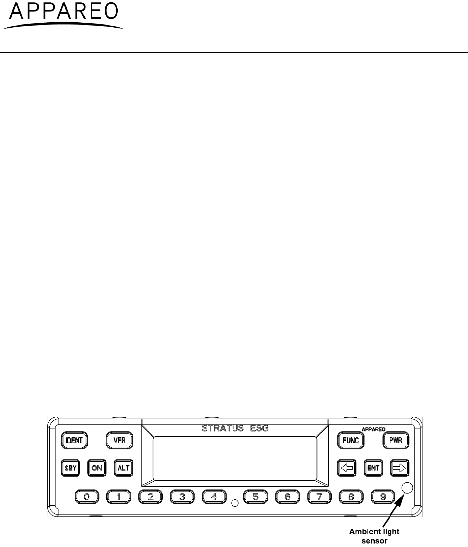
5.3. Analog inputs
1. Enter into configuration mode on Stratus ESG.
2. Press FUNC or the arrow keys to advance to the analog input diagnostics
screen. The screen displays the real-time values read from the lighting bus and
ambient light sensor.
3. Block the ambient lighting sensor input. Verify that the signal percentage drops.
Figure 2: Ambient light sensor location
4. Shine a light on the ambient light sensor. Verify that the signal percentage
increases.
5. If you are using the 14V or 28V lighting bus: Adjust the lighting bus input to
minimum. Verify that the displayed value is 0%.
6. If you are using the 14V or 28V lighting bus: Adjust the lighting bus input to
maximum. Verify that the displayed value is 100%.

600840-000031 Stratus ESG Installation Instructions
Rev. 1.1
Last Revised: January 6, 2016
Page 32 of 42
5.4. Altitude
1. Enter into configuration mode on Stratus ESG.
2. Press FUNC or the arrow keys to advance to the altitude diagnostic screen.
3. Verify that the altitude displayed is correct to your geographic location.
5.5. EMI check
Communications
(i) Cockpit intercom
Using the cockpit intercom, verify interference-free communications between the crew while
monitoring the effects of Stratus ESG.
(ii) Cabin paging
Verify that cabin paging is functioning clearly while monitoring the effects of Stratus ESG.
VHF communications
Set VHF communications radios to multiple frequencies and monitor the effects of Stratus ESG
while transmitting and receiving. At a minimum, the frequencies listed below should be tested, in
addition to locally available frequencies. Each transmission should occur for 35 seconds for
each frequency.
Verify that the CN0 values on the GPS receive diagnostic screen do not drop by 2 dB or more.
Test each frequency in 1 MHz increments between 118 -136.000 MHz.
Test the following frequencies for VHF radios with 25kHz spacing:
121.150 121.175 121.200 121.225
121.250 131.200 131.225 131.250
131.275 131.300 131.325 131.350
Test the following frequencies for VHF radios with 8.33kHz spacing:
121.185 121.190 130.285 131.290
HF communications
If the aircraft is equipped with HF communications radios, set to multiple frequencies and
monitor effects of Stratus ESG while transmitting and receiving. Record the frequencies tested:

600840-000031 Stratus ESG Installation Instructions
Rev. 1.1
Last Revised: January 6, 2016
Page 33 of 42
SATCOM communications
If aircraft is equipped with a SATCOM system, operate the SATCOM equipment while
monitoring the GPS CN0 diagnostic screen. Verify that the CN0 values on the GPS receive
diagnostic screen do not drop by 2 dB or more.
Navigation
(i) VOR / ILS
Verify the operation of each VHF Nav receiver in both VOR and ILS modes (including glide
slope) while monitoring the effects of Stratus ESG. Record the frequencies tested.
108.000 MHZ 108.100 MHZ
(ii) DME
Verify the operation of each DME while monitoring the effects of Stratus ESG. The same
frequencies used for VOR and ILS testing may be used for this test.
(iii) Marker Beacon
Verify the operation of each Marker Beacon Receiver while monitoring the effects of
Stratus ESG. The same frequencies used for the ILS test above may be used.
(iv)ADF
Verify the operation of each ADF receiver while monitoring the effects of Stratus ESG.
Frequencies from each band should be tested when possible. Public broadcast stations are
acceptable for conducting test.
Flight management systems
(i) FMS
Enter a flight plan into each FMS system and verify the display of the track and navigation
information while monitoring the effects of Stratus ESG.
(ii) GPS
Monitor GPS signals for each GPS receiver and verify stability of the signals while monitoring
the effects of Stratus ESG.
Record GPS position coordinates for the aircraft.
(iii) Auto pilot
Verify the function of auto pilot while monitoring the effects of Stratus ESG.

600840-000031 Stratus ESG Installation Instructions
Rev. 1.1
Last Revised: January 6, 2016
Page 34 of 42
Safety equipment
(i) EGPWS / TAWS
Verify the function of the EGPWS and Terrain Display (if equipped) while monitoring the effects
of Stratus ESG.
(ii) TCAS
Verify the function of the TCAS while monitoring the effects of Stratus ESG. Self-test and
monitoring targets of opportunity should both be evaluated.
(iii) Weather radar
Verify the function of each weather radar system while monitoring the effects of Stratus ESG. All
displays capable of showing weather radar should be evaluated.
(iv) Radio altimeter
Verify each radio altimeter system functions correctly while monitoring the effects of
Stratus ESG. Each unit should self-test correctly and be free of continuous variation while
parked on the ramp.
(v) Engine indications & fuel flow (engines operating)
Aircraft must be taken off ground power (if necessary). Start aircraft engines. Check to be
certain that all engine indicators read appropriately.
Check to be certain that all fuel flow indicators read appropriately.
5.6. Compass swing test
After successful completion of the above EMI tests, evaluate the necessity of a swing test.
5.7. Flight test
It is recommended that a flight test be conducted after installation to verify proper operation and
installation of Stratus ESG. A compliance report can be obtained by emailing 9-AWA-AFS-300-
ADSB-AvionicsCheck@faa.gov with the aircraft information. This method is controlled by the
FAA and may be subject to change.
For additional information visit the FAA website: http://www.faa.gov/nextgen/equipadsb/.
6. Using Stratus ESG
See the Stratus ESG Pilot’s Guide (600890-000049) for a full description of Stratus ESG’s
function.
600840-000031 Stratus ESG Installation Instructions
Rev. 1.1
Last Revised: January 6, 2016
Page 35 of 42
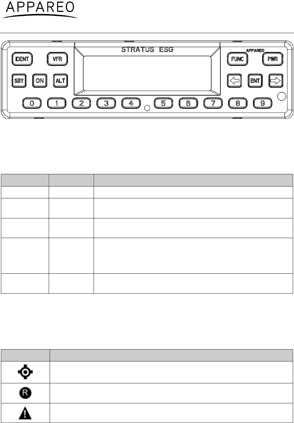
Figure 3: Stratus ESG front panel
6.1. Mode selection keys
Use the mode selection keys to change the transponder mode. The table below describes each
of these modes and during what phase of flight each mode should be used.
Mode
Key
Description
Off
PWR
Stratus ESG is powered off.
Standby
SBY
Stratus ESG is powered on and does not send responses to
any ATC interrogations.
Altitude
ALT
Stratus ESG is powered on and responds to all Mode A/C/S
interrogations. Altitude is reported.
Ground
(none)
Stratus ESG is powered on and in ALT or On mode, but does
not report altitude. This mode is automatically detected, but
ALT or ON keys can override Ground mode. Standby mode
removes this override.
On
ON
Stratus ESG is powered on and responds to all Mode A/C/S
interrogations, but altitude reporting is suppressed.
Table 25: Mode selection keys
6.2. Event indicators
When certain events occur, an indicator will appear on your Stratus ESG display. The table
below describes each indicator’s meaning.
Indicator
Meaning
ADS-B transmission contains GPS position information with a radius of
containment under 1 nautical mile.
A response was transmitted from a mode A/C/S interrogation. The indicator
will time out if another reply does not occur within one second.
A built-in-test (BIT) has failed. See Section 4.19.9 of this document and the
Stratus ESG Pilot’s Guide for more information about BIT failures.
600840-000031 Stratus ESG Installation Instructions
Rev. 1.1
Last Revised: January 6, 2016
Page 36 of 42
Table 26: Event indicators
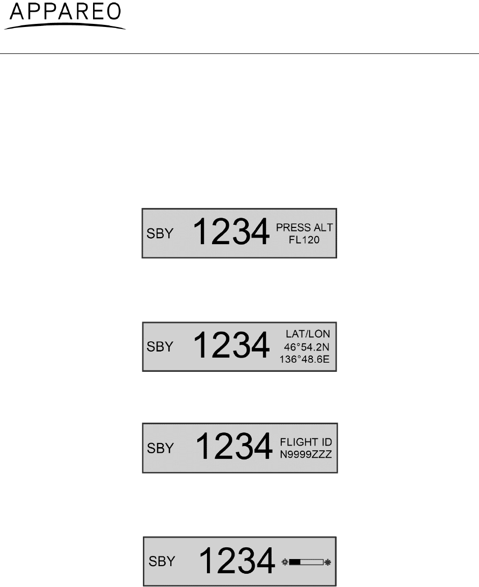
6.3. FUNC key
Press the FUNC key or the arrow keys, to switch from the default screen to the Pressure
Altitude screen, GPS screen, Flight ID screen, and Brightness screen. These screens are
described below:
Pressure altitude screen: Displays the current pressure altitude. If no valid altitude is detected
or Stratus ESG is in On mode, the altitude field will be replaced by dashes.
Figure 4: Pressure altitude screen
GPS screen: Displays the aircraft’s GPS position in degrees latitude and longitude. If no GPS
signal is being received, the latitude and longitude fields will be replaced by dashes.
Figure 5: GPS screen
Flight ID screen: Displays the currently entered Flight ID.
Figure 6: Flight ID screen
Brightness screen: Allows for adjustment of screen brightness in-flight. Press ENT, then the
left or right arrow keys to adjust brightness. Press ENT again to confirm the new setting.
Figure 7: Brightness screen

600840-000031 Stratus ESG Installation Instructions
Rev. 1.1
Last Revised: January 6, 2016
Page 37 of 42
6.4. Other keys
Arrow keys
Use the arrow keys to advance forward and backward when entering numbers or letters and to
cycle through options in Configuration mode. They can also be used for cycling through the
display screens.
Numerical keys
Numerical keys are used to enter information such as the flight ID or squawk code. See
Section 6.5 for directions for how to enter the squawk code for your aircraft’s flight, and see
Section 6.6 for instructions on how to enter a flight ID.
Sometimes, a textual or non-numerical input will be required. If this is the case, press the
number that is associated with the letter group you want to input, according to the graphic on
the screen. To cycle through the letters associated with each number, press the number key
repeatedly until the letter you want to input appears. You can input a space after cycling through
all of the letters for a particular number key. Once the correct character is selected, use the right
arrow key to advance to the next field to enter the next character in the sequence.
Identification (IDENT) key
If you are instructed by Air Traffic Control (ATC) to IDENT, press the IDENT key on your Stratus
ESG. Pressing IDENT will make your aircraft’s reply pulse on ATC’s monitors for 18 seconds.
“IDENT” will be shown on the display while IDENT is activated.
VFR key
Press the VFR key to broadcast the VFR squawk code. The factory set VFR code is 1200, but
the default number may be reconfigured.
Power (PWR) key
The PWR key is used to power Stratus ESG on and off. When Stratus ESG is powered on, it
retains the last used squawk code and operation mode.
6.5. Entering a squawk code
Press the appropriate number keys (0 through 7) to enter the squawk code while on any screen
that the squawk code is shown. The digits will be shown on the display screen. Five seconds
after the fourth digit is entered, Stratus ESG will automatically save the entered squawk code.
NOTE: If you incorrectly enter a number before the code is automatically saved, press the left
arrow key and then press the correct number key.
WARNING: Squawk codes 7500 (hijacking), 7600 (radio failure), and 7700 (emergency) are
reserved for emergencies. There may also be other reserved codes, depending on the region
600840-000031 Stratus ESG Installation Instructions
Rev. 1.1
Last Revised: January 6, 2016
Page 38 of 42
the pilot is flying in. It is the pilot in command’s responsibility to comply with their jurisdiction's
operating rules and regulations.
6.6. Entering the flight identification number
To enter your flight identification number:
1. Press FUNC or the arrow keys until “Flight ID” appears. The registration number will
automatically be displayed in the Flight ID screen.
2. Press ENT.
3. Use the number keys to edit the registration number and overwrite it. Use the left and
right arrow keys to change the cursor position to the previous or next field. See Section
6.4.2 for instructions on how to enter non-numerical input.
NOTE: If the new flight ID is less than 8 digits and there are characters from the
previously entered flight ID still remaining after the new flight ID has been entered, insert
spaces in those fields to overwrite the characters.
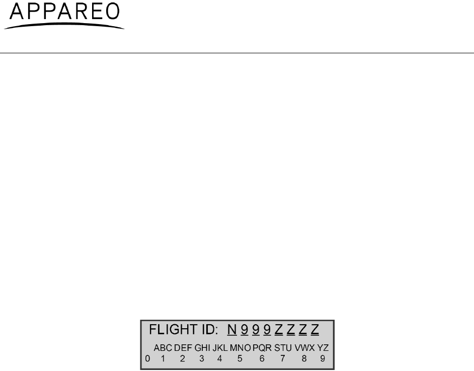
Figure 8: Flight ID entry screen
4. Press ENT to confirm the new flight ID.


600840-000031 Stratus ESG Installation Instructions
Rev. 1.1
Last Revised: January 6, 2016
Page 40 of 42
Appendix A
Nomenclature: Stratus ESG Transponder
Part number: 153510-000017
TSO number: TSO-C112e, TSO-C145d, TSO-C166c
Manufacturer’s specification and/or other applicable specification: 608080-000021
Manufacturer: Appareo Systems
Address: 1830 NDSU Research Circle North, Fargo, ND 58102, USA
Conditions
DO-160G
Section
Description of tests conducted
Temperature and Altitude
4.0
Low Temperature
4.5.2
Equipment tested to Category B1.
High Temperature
4.5.3
Equipment tested to Category B1.
Operating High Temp
Test
4.5.4
Equipment tested to Category B1.
In-Flight Loss of Cooling
4.5.5
Equipment identified as Category X, no test
performed.
Altitude
4.6.1
Equipment tested to Category B1.
Decompression
4.6.2
Equipment identified as Category X, no test
performed.
Overpressure
4.6.3
Equipment identified as Category X, no test
performed.
Temperature Variation
5.0
Equipment tested to Category C.
Humidity
6.0
Equipment tested to Category A.
Operational Shocks and
Crash Safety
7.0
Operational Shocks
7.2
Equipment tested to Category B.
Crash Safety
7.3
Equipment tested to Category B.
Aircraft type: 5F

600840-000031 Stratus ESG Installation Instructions
Rev. 1.1
Last Revised: January 6, 2016
Page 41 of 42
Vibration
8.0
8.5.1
Equipment tested to Category S.
3 during, 1 after
8.8.2
Equipment tested to Category U.
3 during, 1 after
Explosion Proofness
9.0
Equipment identified as Category X, no test
performed.
Waterproofness
10.0
Equipment identified as Category X, no test
performed.
Fluids Susceptibility
11.0
Equipment identified as Category X, no test
performed.
Sand and Dust
12.0
Equipment identified as Category X, no test
performed.
Fungus Resistance Test
13.0
Equipment identified as Category X, no test
performed.
Salt Fog Test
14.0
Equipment identified as Category X, no test
performed.
Magnetic Effect
15.0
Equipment tested to Category A.
Power Input
16.0
Normal Operating
Conditions
16.6.1
Equipment tested to Category BX.
3 during, 2 after
Voltage
16.6.1.1
Equipment tested to Category BX.
Abnormal Operating
Conditions
16.6.2
Equipment tested to Category BX.
3 during, 2 after
Voltage Spike
17.0
Equipment tested to Category A.
Audio Frequency Conducted
Susceptibility
18.0
Equipment tested to Category B.
Induced Signal Susceptibility
19.0
Equipment tested to Category ZCX.
Radio Frequency
Susceptibility
20.0
Conducted Susceptibility
20.4
Equipment tested to Category TT.
Radiated Susceptibility
20.5
Equipment tested to Category TT.
Emission of Radio Frequency
Energy
21.0
Equipment tested to Category B.
Lightning Induced transient
Susceptibility
22.0
Equipment tested to Category A1XXXX.

600840-000031 Stratus ESG Installation Instructions
Rev. 1.1
Last Revised: January 6, 2016
Page 42 of 42
Lightning Direct Effects
23.0
Equipment identified as Category X, no test
performed.
Icing
24.0
Equipment identified as Category X, no test
performed.
Electrostatic Discharge
25.0
Equipment tested to Category A.
No test during, 2 after
Fire, Flammability
26.0
Flammability testing was performed utilizing the
method as indicated in 14 CFR Part 25
Appendix F.