Applied Micro Design 1456FFDPA-800 Model 1456 FFDPA-800 MHz Multi- Carrier In- Building Amplifier User Manual
Applied Micro Design, Inc Model 1456 FFDPA-800 MHz Multi- Carrier In- Building Amplifier
UserManual.wiki
>
Applied Micro Design
>
1456FFDPA 800 User Manual
User Manual
Navigation menu
Upload a User Manual
Namespaces
Wiki Guide
HTML
PDF
Info
Views
User Manual
Discussion / Help
Navigation
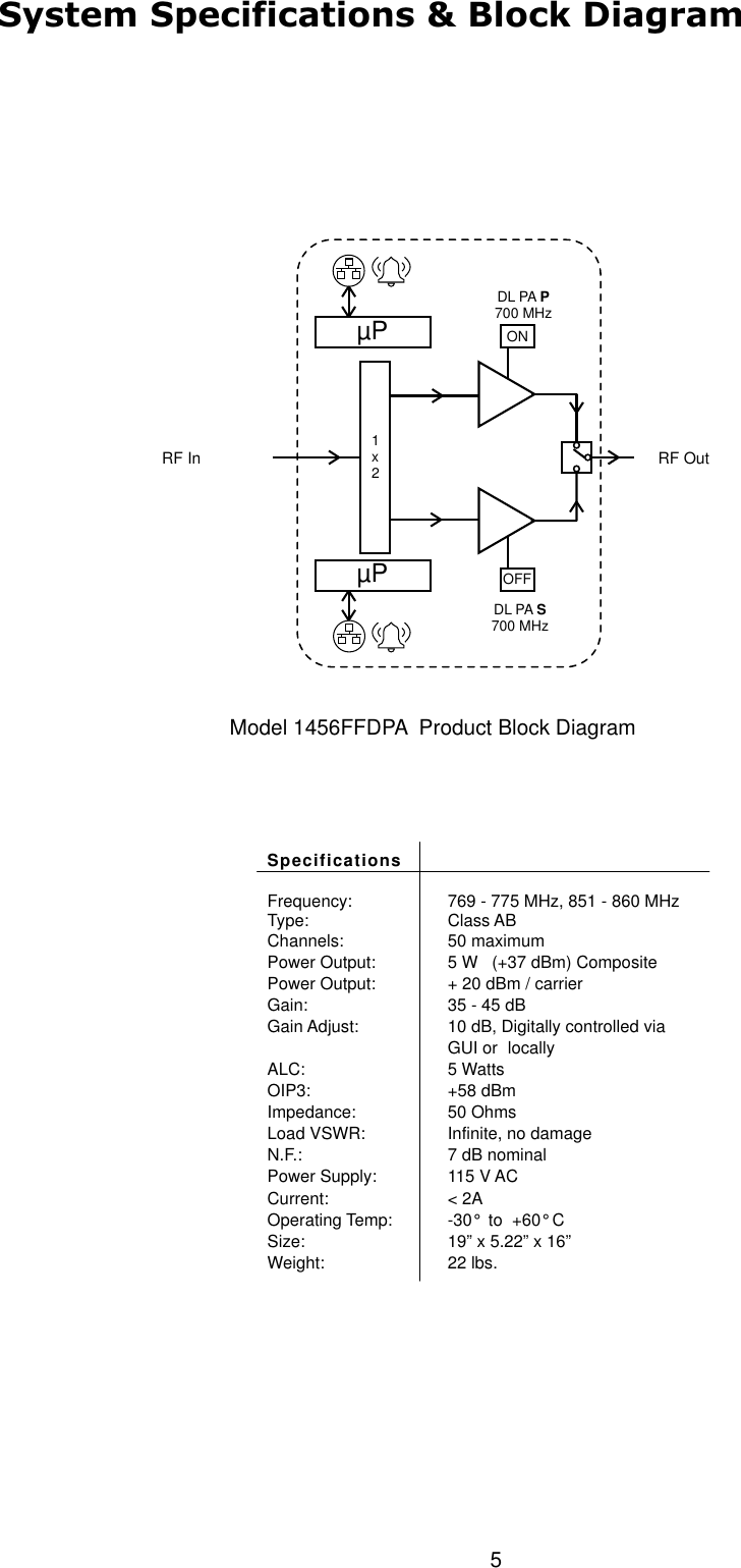
![4This is a Class B Booster.Notes, Cautions, and Warnings!Connect RF Output to existing Distributed Antenna System (DAS) cable only.DO NOT operate equipment with unauthorized antennas, cables, and/or coupling devices.DO NOT operate equipment unless all RF connectors are secure.DO NOT operate equipment unless it has been installed and inspected by a qualified radio technician.Contact InformationFor more information contact the FCC at:https://signalboosters.fcc.gov/signal-boosters/F.2 PART 90 CLASS B SIGNAL BOOSTERS Licensees and signal booster operators are required to register existing Class B signal booster installations with the FCC by November 1, 2014. After November 1, 2014, operation of an existing, unregistered Class B signal booster will be unauthorized and subject to enforcement action. Any new Class B signal booster installed after November 1, 2014 must be registered prior to operation. To encourage compliance with this new requirement, registration will be free of cost to the operator and/or licensee.[R11], [R9] FCC Part 90 Class B Signal Booster Registration & Discovery website:https://signalboosters.fcc.gov/signal-boosters/](https://usermanual.wiki/Applied-Micro-Design/1456FFDPA-800/User-Guide-3152759-Page-4.png)