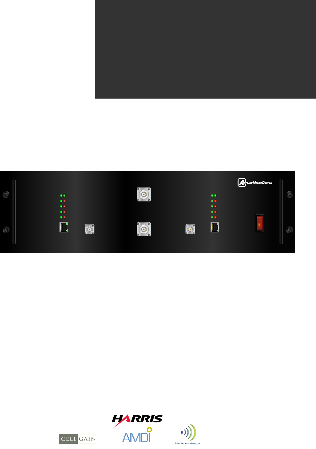
Applied Micro Design 1456FFDPA-800 Model 1456 FFDPA-800 MHz Multi- Carrier In- Building Amplifier User Manual
Applied Micro Design, Inc Model 1456 FFDPA-800 MHz Multi- Carrier In- Building Amplifier
User Manual
City and County of
San Francisco (CCSF)
Underground RF Systems
Replacement Project
Contract No. 1240
Applied Micro Design Inc.
Fiber-Fed Dual Power Amplifier (FFDPA)
User’s Manual
Model 1456FFDPA
UM01456-2201
rev 3
CURRENT FLT
REFL PWRFWD PWR
CURRENT
FAN
TEMP
ETHERNET
FAN FLT
TEMP FLT
STATUS KEY
REFL PWRFWD PWR
PORT 2
SAMPLE
PORT 1
SAMPLE
RF OUT
ETHERNET
CURRENT
TEMP
FAN
TEMP FLT
CURRENT FLT
FAN FLT
POWER
RF IN
STATUS KEY
MODEL 1466FFDPA
DUAL AMPLIFIER
STATUS
FWD PWR REFL PWR
KEY
CURRENT CURRENT FLT
TEMP TEMP FLT
FAN FAN FLT
STATUS
FWD PWR REFL PWR
KEY
CURRENT CURRENT FLT
TEMP TEMP FLT
FAN FAN FLT
RF IN
RF OUT
ETHERNET
DUAL AMPLIFIER
MODEL 1456FFDPA-700
SAMPLE
PORT 1 SAMPLE
PORT 2
ETHERNET
POWER
PRIMARY SECONDARY
RESET
OFF

19516 Amaranth Drive Germantown MD 20874 ph 301.540.9506 | info@appliedmicrodesign.com | www.appliedmicrodesign.com
Applied Micro Design Inc.
PROPRIETARY
This document is issued in strict confidence on condition that it is not copied,
reprinted, or disclosed to a third party, wholly or in part, without written
consent of Applied Micro Design, Incorporated.
2
Table of Contents
Notes, Cautions, and Warnings
System Specifications and Block Diagram
Introduction and Description
Front Panel and Indicators
3
4
This is a Class B Booster.
Notes, Cautions, and Warnings
!Connect RF Output to existing Distributed Antenna System (DAS) cable only.
DO NOT operate equipment with unauthorized antennas, cables, and/or coupling
devices.
DO NOT operate equipment unless all RF connectors are secure.
DO NOT operate equipment unless it has been installed and inspected by a qualified
radio technician.
Contact Information
For more information contact the FCC at:
https://signalboosters.fcc.gov/signal-boosters/
F.2 PART 90 CLASS B SIGNAL BOOSTERS Licensees and signal booster operators are
required to register existing Class B signal booster installations with the FCC by November
1, 2014. After November 1, 2014, operation of an existing, unregistered Class B signal
booster will be unauthorized and subject to enforcement action. Any new Class B signal
booster installed after November 1, 2014 must be registered prior to operation. To
encourage compliance with this new requirement, registration will be free of cost to the
operator and/or licensee.[R11], [R9]
FCC Part 90 Class B Signal Booster Registration & Discovery website:
https://signalboosters.fcc.gov/signal-boosters/
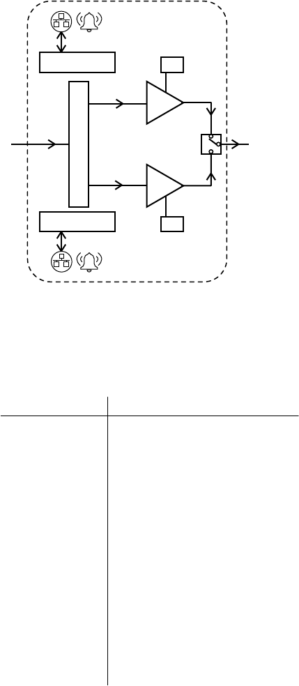
System Specifications & Block Diagram
RF Out
Model 1456FFDPA Product Block Diagram
Specifications
Frequency: 769 - 775 MHz, 851 - 860 MHz
Type: Class AB
Channels: 50 maximum
Power Output: 5 W (+37 dBm) Composite
Power Output: + 20 dBm / carrier
Gain: 35 - 45 dB
Gain Adjust: 10 dB, Digitally controlled via
GUI or locally
ALC: 5 Watts
OIP3: +58 dBm
Impedance: 50 Ohms
Load VSWR: Infinite, no damage
N.F.: 7 dB nominal
Power Supply: 115 V AC
Current: < 2A
Operating Temp: -30° to +60° C
Size: 19” x 5.22” x 16”
Weight: 22 lbs.
DL PA P
700 MHz
1
x
2
DL PA S
700 MHz
ON
OFF
µP
µP
RF In
5
Introduction & Description
The 1456DPA channel amplifier is a high-linearity, multi-carrier amplifier for DAS Distributed
Antenna System applications.
The unit is dual-amplifier configuration. Each amplifier has its own processor board, alarms, panel
indicators and power supply. An RF Switch and Switch Interface Board allow for routing either
amplifier output to the common RF Output connector.
The processor board controls the enable signal (Mute) to the amplifier module and monitors
forward power, reverse power, current, fan status and heat sink temperature.
The processor board features remote monitoring capability via Ethernet. A computer running the
Graphical User Interface (GUI) can display the status of the amplifier and provide control.
A front panel Look Port for each amplifier allows the user to sample each of the two signals at the
front panel. The look port enables measurement without interrupting main line communications.
The Look Port sample is 40 dB below the main RF output port.
6
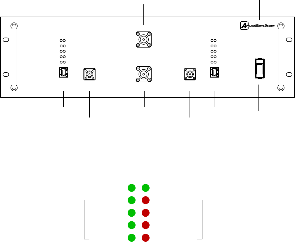
Power
Switch
RF In
Connector
-40 dB
Sample Port 2
Connector
-40 dB
Sample Port 1
Connector
Ethernet
Connector
192.168.7.xxx
IP Address
192.168.7.xxx
IP Address
STATUS KEY
REFL PWR
CURRENT FLT
TEMP FLT
FAN FLT
FWD PWR
CURRENT
TEMP
FAN
FFDPA - Front Panel and Indicators
Model No. 1456FFDPA
steady: amplifer is operating steady: amplifier is enabled
steady: amplifier is operating
normally steady: amplifier has either
current, reverse power or
temperature fault
CURRENT FLT
REFL PWRFWD PWR
CURRENT
FAN
TEMP
ETHERNET
FAN FLT
TEMP FLT
PRIMARY
STATUS KEY
REFL PWRFWD PWR
PORT 2
SAMPLE
PORT 1
SAMPLE
RF OUT
ETHERNET
CURRENT
TEMP
FAN
TEMP FLT
CURRENT FLT
FAN FLT
POWER
RF IN
SECONDARY
STATUS KEY
MODEL 1456FFDPA-700
DUAL AMPLIFIER
Ethernet
Connector RF Out
Connector
Model Number and
Frequency Band
7
8
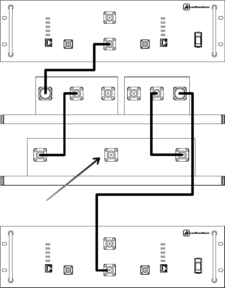
Power Amplifier Installation
769-775 MHz 799-805 MHzCOM 806-815 MHz 851-860 MHzCOM
760-805 MHz 806-860 MHzCOM
CURRENT FLT
REFL PWRFWD PWR
CURRENT
FAN
TEMP
ETHERNET
FAN FLT
TEMP FLT
PRIMARY
STATUS KEY
REFL PWRFWD PWR
PORT 2
SAMPLE
PORT 1
SAMPLE
RF OUT
ETHERNET
CURRENT
TEMP
FAN
TEMP FLT
CURRENT FLT
FAN FLT
POWER
RF IN
SECONDARY
STATUS KEY
MODEL 1456FFDPA-700
DUAL AMPLIFIER
CURRENT FLT
REFL PWRFWD PWR
CURRENT
FAN
TEMP
ETHERNET
FAN FLT
TEMP FLT
PRIMARY
STATUS KEY
REFL PWRFWD PWR
PORT 2
SAMPLE
PORT 1
SAMPLE
RF OUT
ETHERNET
CURRENT
TEMP
FAN
TEMP FLT
CURRENT FLT
FAN FLT
POWER
RF IN
SECONDARY
STATUS KEY
MODEL 1456FFDPA-800
DUAL AMPLIFIER
Connect to Distributed
Antenna System (DAS)
FFDPA-700
DUPLEXER
CBC
FFDPA-800
Cables shown above are shipped with the units.

Related Documents
19516 Amaranth Drive Germantown MD 20874 ph 301.540.9506 | info@appliedmicrodesign.com | www.appliedmicrodesign.com
Applied Micro Design Inc.
9