Applied Wireless Identifications Group MPR-2010AN RFID FHSS Reader User Manual 499501
Applied Wireless Identifications Group Inc. RFID FHSS Reader 499501
UserManual.wiki
>
Applied Wireless Identifications Group
>
MPR 2010AN User Manual
users manual
Navigation menu
Upload a User Manual
Namespaces
Wiki Guide
HTML
PDF
Info
Views
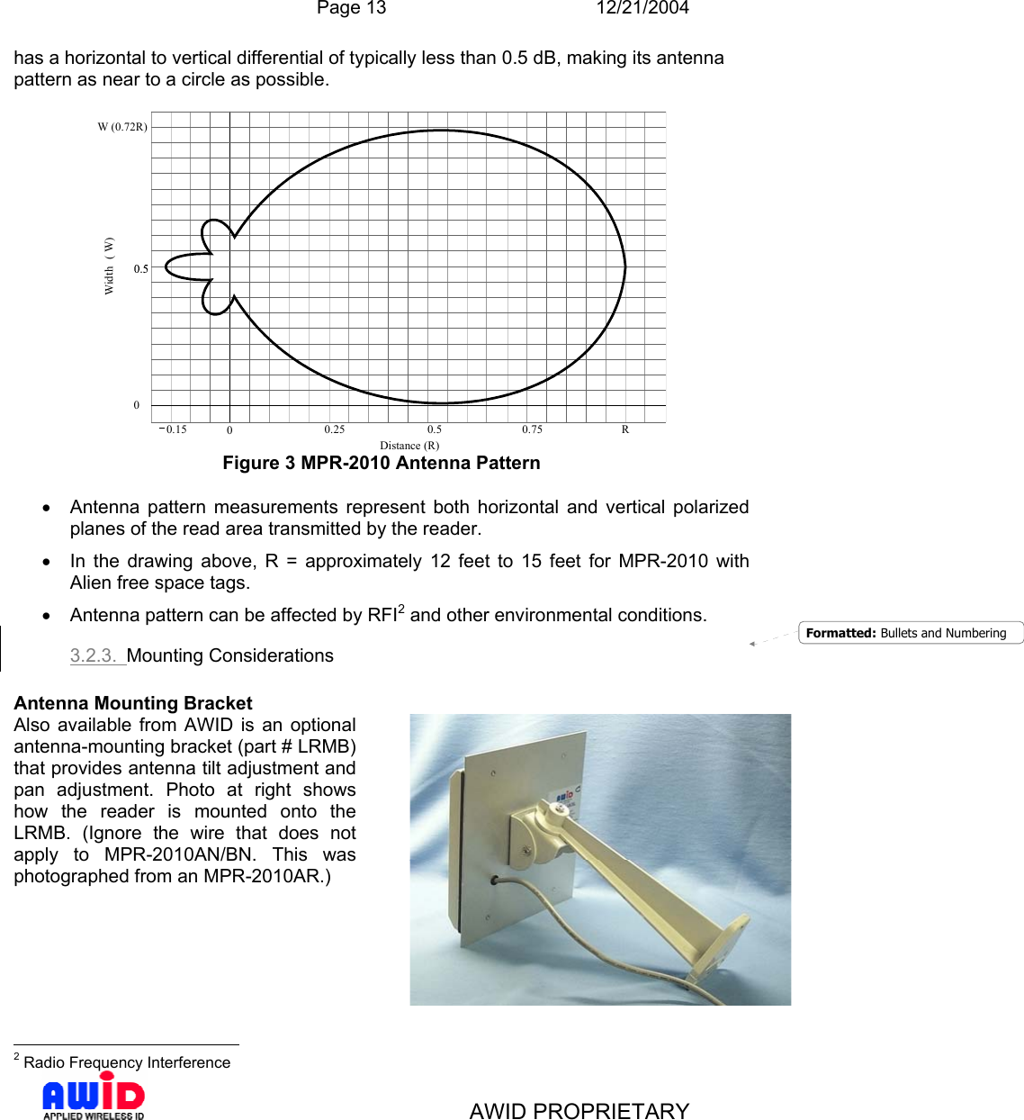
User Manual
Discussion / Help
Navigation