Applied Wireless Identifications Group MPR-2010AN RFID FHSS Reader User Manual 499501
Applied Wireless Identifications Group Inc. RFID FHSS Reader 499501
users manual

Page 1 12/21/2004
AWID PROPRIETARY
SENTINEL-SENSE MPR-2010
MPR-2010AN Ver. 1.21N
DRAFT
Installation & Operation Manual - 007-04-A
Note: This manual is for Ethernet version only!
For RS-232 version, please refer to Manual-007-03-A
Updated: December 21, 2004

Page 2 12/21/2004
AWID PROPRIETARY
COPYRIGHT A CKNOWLEDGEMENTS
The contents of this document are the property of Applied Wireless Identifications Group, Inc.
(AWID) and are copyrighted. All rights reserved. Any reproduction, in whole or in part, is
strictly prohibited. For additional copies of this document please contact:
AWID
382 Route 59, Section 292
Monsey, NY 10952
www.sales-ast@AWID.com
The information contained herein has been carefully checked and is believed to be accurate,
no responsibility is assumed for inaccuracies. AWID reserves the right to make changes
without prior notice. This document is not covered by any warranty either expressed or
implied. Any comments, corrections or additions to the contents of this document should be
directed to AWID at the above address.
Copyright 2003 AWID, Printed in USA.
All other trademarks are the property of their respective owners.
FCC COMPLIANCE
This equipment has been tested and found to be in compliance with the limits for FCC Part 15,
Class A digital device. These limits are designed to provide reasonable protection against
harmful interference when the equipment is operated in a commercial environment. This
equipment generates, uses and can radiate radio frequency energy and, if not installed and
used in accordance with instruction manual, may cause harmful interference with radio
communications. Operation of this equipment in a residential area is likely to cause harmful
interference in which case the user will be required to correct the interference at his own
expense.
The users are prohibited from making any change or modification to this product, any
modification to this product shall void the user’s authority to operate under FCC Part 15
Subpart A Section 15.21 regulations.
"This device complies with Part 15 of the FCC Rules. Operation is subject to the following
two conditions: (1) This device may not cause harmful interference, and (2) this device must
accept any interference received, including interference that may cause undesired
operation."
INDUSTRY C ANADA COMPLIANCE
Operation is subject to the following two conditions: (1) this device may not cause
interference and (2) this device must accept any interference, including interference that
may cause undesired operation of the device.
C AUTION:
Reader should be positioned so that personnel in the area for prolonged periods may
safely remain at least 23 cm (9 in) in an uncontrolled environment from the reader’s surface.
Observe FCC OET Bulletin 56 “Hazards of radio frequency and electromagnetic fields” and
Bulletin 65 “Human exposure to radio frequency electromagnetic fields.”

Page 3 12/21/2004
AWID PROPRIETARY
Table of Content
TABLE OF CONTENT............................................................................................................... 3
1. INTRODUCTION................................................................................................................ 5
1.1. GENERAL DESCRIPTION & THEORY OF OPERATION ......................................................... 5
1.2. SPECIAL FEATURES ......................................................................................................... 7
1.3. MODEL NUMBER ASSIGNMENT........................................................................................ 8
2. SPECIFICATIONS.............................................................................................................. 9
2.1. INPUT AND OUTPUT INTERFACES & CONNECTOR PIN ASSIGNMENT ................................. 9
2.1.1. Power through spare wires....................................................................................10
2.1.2. Power through data wires. ....................................................................................10
2.1.3. General Purpose Input/Output ..............................................................................10
2.2. MEASURING READ DISTANCE.........................................................................................11
3. INSTALLATION PROCEDURE ......................................................................................12
3.1. PARTS LIST ....................................................................................................................12
3.2. PREPARATION FOR INSTALLATION ..................................................................................12
3.2.1. Bench Top Verification..........................................................................................12
3.2.2. Aiming of Antenna.................................................................................................12
3.2.3. Mounting Considerations ......................................................................................13
3.3. INSTALLATION STEPS .....................................................................................................14
4. NOTES ON SOFTWARE PROGRAMMING AND SYSTEM OPERATION ..............15
4.1. SET UP AND SYSTEM OPERATION..................................................................................15
4.1.1. Setting Up MPR-2010AN or BN ............................................................................15
4.1.2. Running a Custom Software Application or the AWID Demo Program.................15
4.1.3. Operating Modes...................................................................................................15
4.2. USERS NOTE ..................................................................................................................16
5. REFERENCE......................................................................................................................16
6. APPENDIX..........................................................................................................................18
6.1. NETWORK SET UP DIAGRAM ..........................................................................................18
6.2. LOCAL SET UP DIAGRAM ...............................................................................................20
Figure 1 Block Diagram, Single-Antenna RFID Reader .................................................... 7
Figure 2 Block Diagram, Dual-Antenna RFID Reader ....................................................... 7
Figure 3 MPR-2010 Antenna Pattern............................................................................... 13
Figure 4 Four MPR-2010AN/BN Networked via PI-2000................................................. 18
Figure 5 Four MPR-2010AN/BN Networked via PoE Switch/Router............................... 19
Figure 6 Local Set Up without Ethernet Hub.................................................................... 20
Figure 7 Local Set Up with an Ethernet Hub.................................................................... 20
..........................................................................................................................................................................................................................

Page 4 12/21/2004
AWID PROPRIETARY
NOTE: READ AND USE THIS MANUAL.
FAILURE TO DO SO MAY RESULT IN POOR READER PERFORMANCE OR
EVEN PERMANENT DAMAGE TO READER, WHICH COULD VOID THE
READER WARRANTY.
FAILURE TO FOLLOW THE INSTALLATION (SET UP) GUIDE MAY RESULT IN
POOR PERFORMANCE OR EVEN CAUSE PERMANENT DAMAGE TO THE
READER, THUS VOIDS THE PRODUCT WARRANTY.

Page 5 12/21/2004
AWID PROPRIETARY
1. INTRODUCTION
AWID's Sentinel-Sense MPR-2010AN Ver. 1.21N is a long-range (12 to 15 feet) reader
with TCP/IP interface and general purpose digital I/O (GP I/O - four (4) input four (4)
outputs) that works with most leading passive UHF passive tags. This reader comes with
a unique combination of long read range, small size, and low power consumption. MPR-
2010 has an internal power converter, allowing it to work with a wide range of supply
inputs without affecting its performance. Its primary applications are asset management
and tracking, and fleet management applications.
The MPR-2010 reader is delivered with the following components and accessories:
• MPR reader – MPR-2010AN or MPR-2010BN, Firmware Ver. 1.21N
• Optional where PoE switch or router is not available:
o Power supply – PS48-03A-SW, 50-60 Hz and 110 to 220 VAC.
o Power Injector – PI-2000
o RJ-45 Cable
In order to control the MPR reader you will need the following:
• PC running Windows 98 or higher, CD-ROM drive Network connection
• Host software (AWID’s demo software or your own custom software).
• RFID Tags (EPC Class 0, 1, ISO Type B or EM Micro)
1.1. GENERAL DESCRIPTION & THEORY OF OPERATION
This Radio Frequency Identification (RFID) reader uses radio frequency to identify,
locate and track pallets and/or items that carry the appropriate RFID transponders.
MPR-2010 readers work in non-line-of-sight situations and in darkness, bright sun-light,
or through dirt, grime and smudges.
A typical RFID system consists of three components – a reader (interrogator), a
transponder (card or tag), and a data processing controller. MPR-2010 has an internal
micro-controller section, a transmitter section, a receiver section, and a circular polarized
transmit/receive antenna. Passive transponders (tags or labels) consist of an antenna
and an RFID ASIC (Application Specific Integrated Circuits). During operation, the
transmitter sends out an electromagnetic wave to establish a zone of surveillance. When
a transponder enters this zone, the electromagnetic energy from the reader begins to
energize the IC in the transponder. Once the IC is energized, it goes through an
initialization process and is ready to accept further commands. Upon receiving a
command that queries its identity, the RFID ASIC begins to broadcast its identity through
a low-energy back-scattering process, which selectively reflects or “back-scatters” the
electromagnetic energy back to the interrogator. The receiving circuits in the reader
sense and decode this “back-scattered” signal and determine the identity of the
transponder.
Formatted: Bullets and Numbering
Deleted: RS-232 I/O
Deleted: pr
Deleted: s
Deleted:
Deleted:

Page 6 12/21/2004
AWID PROPRIETARY
Passive tags are “beam powered”, which is the electromagnetic energy radiated by the
transmitter section of the reader. Upon receiving a legitimated command, the tags will
cause the matching of the tags antenna to vary from match to mismatch, thereby causing
the tags to either absorb the RF energy or to reflect the RF energy. This absorption or
reflection sequence is commanded by the tag’s internal memory and this is how the tag’s
internal data are “conveyed” to the reader. The reader in turn monitors the perturbation of
the RF energy field, and thereby receives the varying degree of signal reflected from the
tag.
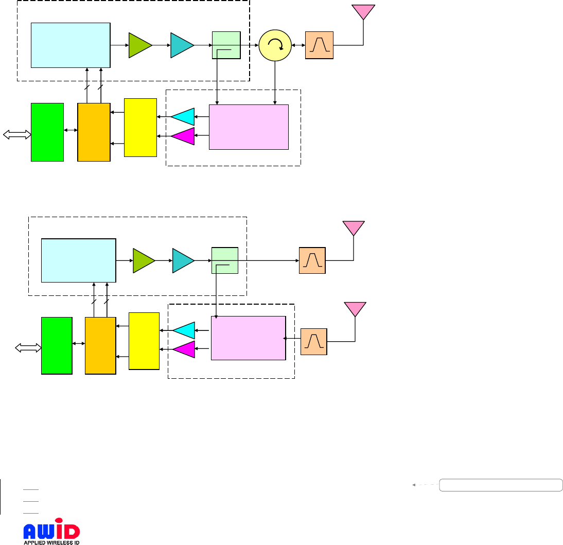
One of the unique design features for an RFID reader is that it must simultaneously
transmit a strong CW signal, while at the same time, receives a weak reflected signal
with little frequency separation. In a traditional design, such functions are implemented
through the use of a circulator. As shown in Figure 1, there is a 3-port device between
the Coupler and the band pass filter, which is called a circulator. A circulator is physically
constructed by a permanent magnet, a Y junction on a high-dielectric ferromagnetic
substrate, and a ferromagnetic enclosure to complete the flux field. A circulator permits
flow of RF energy in one direction only, e.g. from port 1 to 2, 2 to 3, and 3 to 1. When
one of the ports is terminated (matched condition), the other two are isolated in the
reverse direction. Many fixed-site RFID readers use circulators to ensure that the power
amplifier output flows from the amplifier (port 1) to the antenna (port 2), and the received
signal flows from the antenna (port 2) to the receiver (port 3). When properly matched, a
circulator can provide typically 15 to 18 dB of isolation between the power amplifier
output (port 1) and the receiver input (port 3), thereby reducing any in-band interference
from transmitter output to receiver input. MPR-2010 uses a similar circuit to accomplish
the same function, but in a much smaller physical size.
It should be noted that some fixed-site reader designs use separate transmit and receive
antennas to resolve this T/R signal isolation problem. Figure 2 is a block diagram of a
dual-antenna RFID reader. On the surface, this design has the advantage of allowing a
low-level design on the receive chain, which means lower compression point for mixers,
lower saturation point for amplifiers, and the possibility of using a front-end amplifier to
enhance receiver sensitivity. Such dual-antenna design becomes problematic in a mobile
environment, where signal strength is not easily controlled. A well-designed dual-antenna
reader can usually provide 25 to 30 dB of isolation between the two signal paths,
reducing the unwanted signal in the receive chain to –20 dBm. However, when the RFID
reader antenna is facing a tag placed on a large metallic object at a distance of 12
inches, the reflected transmitter signal at the receiver input can be as high as 13dBm,
thereby eliminating any advantage of the dual-antenna design.
In actual circuit implementation, AWID developed a proprietary circuit to duplicate the
functions of the circulator, with improved directivity and isolation.
Page 7 12/21/2004
AWID PROPRIETARY
Figure 1 Block Diagram, Single-Antenna RFID Reader
Figure 2 Block Diagram, Dual-Antenna RFID Reader
1.2. SPECIAL FEATURES
• Multi-Protocol:
Standard Version: ISO-18000-6 Type A/B, Dura-label, MH-10, AIAG
Version AN: EPC Class 1, EM Micro, ISO-18000-6 Type A/B, MH-10, AIAG
Version BN: EPC Class 1 & 0, EM Micro, ISO-18000-6 Type A/B, MH-10, AIAG
FREQUENCY
SYNTHESIZER
I/Q
DEMOD
Driver
AMP
Power
AMP COUPLER XMIT/
RCVE
A/D
CPU I/O
XMTR
CIRCULATOR
BPF
RCV
IO RF
I
O
I
O
FRE
Q
AMPL
12
3
RCVE
XMIT
RF
O
O
RCV
R
FREQUENCY
SYNTHESIZER
Driver
AMP
Power
AMP
COUPLER BPF
BPF
A/D
CPU I/O
I
I/O DEMOD
IO
I
O
FRE
Q
AMPL
XMT
R
Formatted: Bullets and Numbering

Page 8 12/21/2004
AWID PROPRIETARY
• Thin passive tags with long-range performance
• High performance circular polarized antenna
• RS-232 outputs, with two optional peripheral drivers, one TTL input
• Splash proof design for indoor or outdoor applications
• UV stabilized housing
1.3. MODEL NUMBER ASSIGNMENT
Part number description: A typical number is MPR-2010AN Ver. 2.21N
MPR – MPR – Multiple-protocol RFID
12#XZW– PC Card (PCMCIA) RFID readers
15#XZW– Handheld family of RFID readers
20#XZW– Integral reader/antenna design.
X – Antenna configuration: 0 – Internal antenna, 1 – external antenna
Z – Hardware version: A, B
W – Hardware version: R - RS-232, N - Ethernet, and I - IEEE RS-485.
Ver. X.XX signifies the firmware version in the reader
Examples:
MPR-2010AR (RS-232) – EPC C1, ISO & EM
915 MHz Integral RFID reader with RS-232 I/O interface, that complies with EPC Class
1, ISO-18000-6 Type B, EM Micro protocols.
MPR-2010AN (Ethernet) – EPC C1, ISO & EM
915 MHz Integral RFID reader with Ethernet I/O & PoE interface, that complies with EPC
Class 1, ISO-18000-6 Type B, EM Micro1.
MPR-2010BR (RS-232) – EPC C1, C0, ISO & EM
915 MHz Integral RFID reader with RS-232 I/O interface, that complies with EPC Class
0, Class 1, ISO-18000-6 Type B, EM Micro protocols.
MPR-2010BN (Ethernet) – EPC C1, C0, ISO & EM
915 MHz Integral RFID reader with Ethernet I/O & PoE interface, that complies with EPC
Class 0, Class1, ISO-18000-6 Type B, EM Micro.
MPR-2080AR (RS-232)
866 MHz Integral RFID reader with RS-232 I/O interface, that complies with EPC Class
1, ISO-18000-6 Type B, EM Micro protocols.
MPR-2080AN (Ethernet)
866 MHz Integral RFID reader with Ethernet I/O & PoE interface, that complies with EPC
Class 1, ISO-18000-6 Type B, EM Micro.
1 Support of EPC C0 is also true for MPR-2010AN/AR except performance is not as good as with MPR-
2010BN/BR due to HW difference.
Formatted: Bullets and Numbering

Page 9 12/21/2004
AWID PROPRIETARY
MPR-1230
PC Card reader with internal antenna, 13.56 MHz RFID reader with EPC, ISO-15693,
Tag-It, I-Code, Checkpoint, software version X.XX .
2. SPECIFICATIONS
Input voltage ............................................................RS-232 Version: +6.5 VDC to +15 VDC
............................................................................Ethernet Version: +37 VDC to +56 VDC
Input current.............................................................RS-232: 1.0 A (6.5 V) to 0.40 A (15 V),
typical
............................................................................Ethernet Version: 300 mA, Max
Protocol language
• 2010: ISO-18000-6 Type A/B, Dura-label, MH-10, AIA
• 2010A: ...................... EPC Class 1, EM Micro, ISO-18000-6 Type A/B, MH-10, AIAG
• 2010B: ...................... EPC Class 1 & 0, EM Micro, ISO-18000-6 Type A/B, MH-10, AIAG
Read range .............................................................Depends on type & size of labels used
Output power ...........................................................1.0 Watt into 6 dB antenna
Transmit frequency ..................................................902-928 MHz
Receiver frequency..................................................902-928 MHz (Amplitude Modulated)
Hopping channels ....................................................50 Channels
Channel spacing ......................................................500 kHz
Hopping sequence...................................................Pseudo random
Operating temperature range ..................................-30° C to +65° C (-22° F to 149° F)
Color ........................................................................Beige
Output data formats .................................................RS-232 Version:
............................................................................Ethernet Version: TCP/IP
GP I/O Input.............................................................RS-232 Version: 1-input, 2-output
............................................................................Ethernet Version: 2-input, 2-output
GP I/O Connector ....................................................RS-232 Version: DB-9 connector
............................................................................Ethernet Version: RJ-45 & terminal block
Dimension ................................................................8X9.5X1.125 inches (20X24X2.86 cm)
Weight......................................................................1,100 g (2.4 lb)
2.1. INPUT AND OUTPUT INTERFACES & CONNECTOR PIN ASSIGNMENT
MPR-2010AN and MPR-2010BN are equipped Power over Ethernet (PoE) circuit that
complies with Carrier Sense Multiple Access with Collision Detection (CSMA/CD) access
method and physical layer specifications standards (IEEE 802.af). MPR-2010AN and BN
can work with the following different PoE configurations, power through spare pairs or
power through data lines with automatic polarity sensing.
Page 10 12/21/2004
AWID PROPRIETARY
2.1.1. Power through spare wires
Ethernet connector (RJ45) Power through Spare Pairs
Pin # Function description
1 TX+
2 TX-
3 RX+
4 -48V RTN
5 -48V RTN
6 RX-
7 -48V
8 -48V
2.1.2. Power through data wires.
Ethernet connector (RJ45) Power through Data Pairs
Pin # Function description
1 TX+
2 TX-
3 RX+
4 Spare+
5 Spare+
6 RX-
7 Spare-
8 Spare-
2.1.3. General Purpose Input/Output
Terminal block – 4 inputs & 4 outputs (optically isolated)
Pin # Function description (Pin 10 near LED)
1 Input 1
2 Input 2
3 Input 3
4 Input 4
6 Output Common
7 Output 4
8 Output 3
9 Output 2
5 Input Common 10 Output 1
The four general-purpose inputs that use photo diodes are used to accept TTL input
commands. Each input require 15 mA and 5V to activate. The four outputs are solid-state
relays, with 0.03 uA off-state leakage current and the ability to sink 120 mA at a
breakdown voltage of 400V DC. All outputs are protected with reverse clamping diodes,
and ready to drive inductive loads. The floating arrangement eliminates any ground loop
considerations.
Deleted: 2
Deleted: 2
Deleted: 1
Deleted: Output
Deleted: 5
Deleted: 2
Deleted: Output 1 RTN
Deleted: 6
Deleted: 2 RTN
Deleted: 1
Deleted: 7
Deleted: Input
Deleted: 2
Deleted: 1 RTN
Deleted: 8
Deleted: Input 2 RTN
Deleted: 

Page 11 12/21/2004
AWID PROPRIETARY
2.2. MEASURING READ DISTANCE
Make sure you know the tag types. For certain readers and tags, the user must also be
mindful of the tag’s orientation and the reader’s antenna orientation, what mounting
surface the tags are designed for and how the tags are supposed to be mounted. Any
departure from its intended purpose will drastically affect the reader’s ability to energize
the tag and its read range.
When measuring the reader’s read range, make sure that the tag is properly oriented to
the reader antenna, and for optimum performance, be sure the operator’s finger is not
within three (3) inches of the tag’s antenna surface.

Page 12 12/21/2004
AWID PROPRIETARY
3. INSTALLATION PROCEDURE
This section provides installation and operation information for MPR readers.
Verify that all items listed below are present before starting the installation.
3.1.
PARTS LIST
a. Set Up Guide (Reference I, packed inside Reader carton)
Qty=1
b. Sentinel-Sense MPR-2010, P/N: 007-20-A Qty=1
c. Demo Program CD Qty=1
d. LRMB – Reader mounting bracket (Optional)
3.2. PREPARATION FOR INSTALLATION
3.2.1. Bench Top Verification
It is always a good idea to verify system operation before committing to a full-scale
installation (e.g., as shown in Figure 4, page 18). The following are the necessary steps
to test reader’s operation in a static environment.
• You must first check to see if your network switch or router is equipped with PoE
(Power over Ethernet).
If switch is PoE, connect network cable to just one (1) MPR-2010AN/BN unit.
Skip the next two steps unless the IP address of connected unit cannot be
obtained.
• If your network is not equipped with PoE, obtain a power injector (PI-2000), and 48V
DC wall plug power supply and a short network RJ-45 cable (all available from AWID
under part number PI-2000, PS48-03A and RJ-45 cable).
• Connect the RJ-45 cable between the reader and “READER” port of PI-2000,
connect the wall plug power supply to POWER port of PI-2000 and connect the
Ethernet (RJ-45) cable from the Ethernet Hub (if in use) to “HUB or SWITCH” port of
PI-2000 or in the case where there is no such hub, connect from PC to the port using
a Crossover CAT5 cable.
Power up computer
Follow instructions on Local Set Up (Figure 6 or Figure 7) of an MPR-2010AN.
• Load the demo program CD onto (installation) PC and launch the demo program. Try
Connect after filling in the IP address of reader and then some commands once
connected.
3.2.2. Aiming of Antenna
Antenna Pattern for MPR-2010
MPR-2010 comes with a circular polarized antenna, to ensure reading tag with random
orientation. Most circular polarized antenna has a horizontal to vertical differential of up
to 3 dB, this will cause the antenna pattern to deviate from a true circle. AWID’s antenna
Formatted: Bullets and Numbering
Formatted: Bullets and Numbering
Formatted: Bullets and Numbering
Formatted: Bullets and Numbering

Page 13 12/21/2004
AWID PROPRIETARY
has a horizontal to vertical differential of typically less than 0.5 dB, making its antenna
pattern as near to a circle as possible.
0.15 00.25 0.5 0.75 R
0
Distance
(
R
)
Width( W)
W (0.72R)
Figure 3 MPR-2010 Antenna Pattern
• Antenna pattern measurements represent both horizontal and vertical polarized
planes of the read area transmitted by the reader.
• In the drawing above, R = approximately 12 feet to 15 feet for MPR-2010 with
Alien free space tags.
• Antenna pattern can be affected by RFI2 and other environmental conditions.
3.2.3. Mounting Considerations
Antenna Mounting Bracket
2 Radio Frequency Interference
Also available from AWID is an optional
antenna-mounting bracket (part # LRMB)
that provides antenna tilt adjustment and
pan adjustment. Photo at right shows
how the reader is mounted onto the
LRMB. (Ignore the wire that does not
apply to MPR-2010AN/BN. This was
photographed from an MPR-2010AR.)
Formatted: Bullets and Numbering

Page 14 12/21/2004
AWID PROPRIETARY
3.3. INSTALLATION STEPS
• Check to ensure that all connections are secure. Make sure all wires through the
cable clamps are anchored properly; avoid dangling wires that may become safety
hazard.
• Mount the Reader using the two recessed threaded holes to fasten to reader on the
desired mounting surface. Please note that the threaded inserts are closed ended,
user must select screws with exact length to ensure proper tightening of the
mounting screws. In cases where the reader aiming is critical, please order antenna-
mounting bracket (P/N LRMB) from AWID. This mounting bracket provides pan/tilt
adjustment for the reader. User can also drill holes through the plate as required at
the desired distance from the Reader.
Formatted: Bullets and Numbering

Page 15 12/21/2004
AWID PROPRIETARY
4. Notes on Software Programming and System Operation
4.1. SET UP AND SYSTEM OPERATION
4.1.1. Setting Up MPR-2010AN or BN
Refer to the Set Up Procedure for MPR-2010AN/BN document.
4.1.2. Running a Custom Software Application or the AWID Demo Program
If AWID Demo Program is not used, it is expected user will launch a Custom Software
Application developed using the MPR_2010AN/BN TCP/IP Interface to send commands
as specified to the reader.
4.1.3. Operating Modes
Typical operating modes for MPR-2010 can be grouped into the following modes:
Search Mode – This mode is used when operator or user is not certain which family of tags is
placed on the items to be tracked. Since most tags are deterministic in nature, the reader must
cycle through each and every protocol, issue a protocol specific inquiry, to hail and to wait for a
response from tags of that specific protocol. Therefore, if there are many different protocols, for
an untrained observer, the reader response will become sluggish.
Mixed Mode:
This mode assumes the user is aware of the types of protocol in use, and furthermore, the
user made a determined effort to operate the reader in a mixed protocol mode. In this
mode, the user can decide how many and which specific protocols to be selected. Once
Mix Protocol Mode is selected, the reader will routinely cycle through each protocol, dwell
long enough for the reader to wait for a response and then move onto the next protocol. It
should be noted that in a mixed protocol mode, the tag must have sufficient time to
respond to the reader, and therefore, it can only be used on a conveyor belt arrangement,
with specific speed restrictions.
Single Protocol Mode
Single protocol is the normal mode of operation, where the protocol type is known and
many tags are expected to pass through the readers.
Interactive Read Mode
TBD
Autonomous Read Mode3
When the reader is in autonomous mode, the reader is placed under the control of its two
sensing inputs, which will most likely be in the form of photo sensors, ground loop
sensors, weight triggering mechanism or simple remote command. Upon receiving the
sensing input, the reader will switch to a pre-programmed single-protocol, multi-protocol
and in the case of a conveyor installation, fast-read mode and start reading functions.
Upon intercept of a RFID tag, the reader will automatically output the tag ID and after a
3 Not yet available in 1.21N.

Page 16 12/21/2004
AWID PROPRIETARY
pre-programmed period of in-activity, the reader will switch to stand-by and wait for input
from the sensing commands.
4.2. USERS NOTE
For System Integrators and/or Software Developers
System Integrators and/or Software developers should get familiar with the MPR-2010
TCPIP Interface (Reference II) specifications for developing applications that control
MPR-2010AN or BN readers.
For Custom System Users
For custom system user, please refer to your host software user guide for information
regarding system and software operations
For Demo Software Users
If you are using the AWID RFID demonstration software application which is .NET based
with easy-to-follow GUI operations, simply fill in the IP address of MPR-2010AN/BN
installed then click “Connect” should get you started.
5. Reference
I. Set Up Procedure for MPR-2010AN/BN – 007-04-B
II. MPR-2010 TCP/IP Interface – 007-04-D
Formatted: Bullets and Numbering
Formatted: Bullets and Numbering

Page 17 12/21/2004
AWID PROPRIETARY
Page 18 12/21/2004
AWID PROPRIETARY
6. Appendix
Shown in this Appendix section are diagrams for some possible Set Up scenarios of
MPR-2010AN/BN.
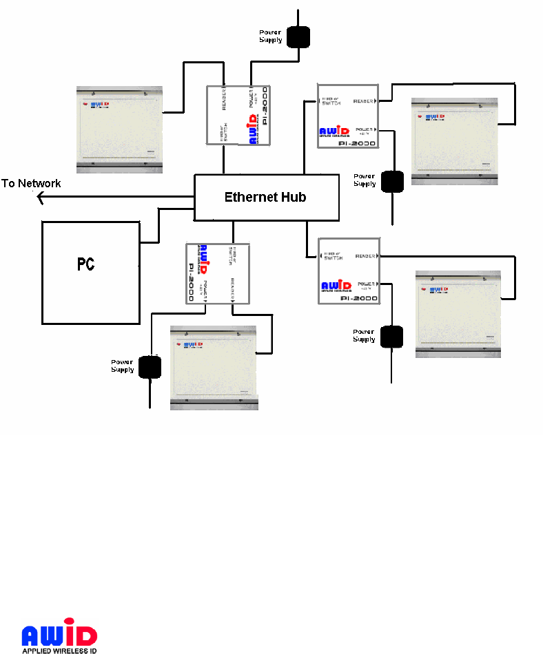
6.1. NETWORK SET UP DIAGRAM
Multiple MPR-2010AN/BN units can be networked using either Power Injector units from
AWID (PI-2000) or a Power-Over-Ethernet (PoE) Switch/Router as depicted below.
Figure 4 Four MPR-2010AN/BN Networked via PI-2000
Page 19 12/21/2004
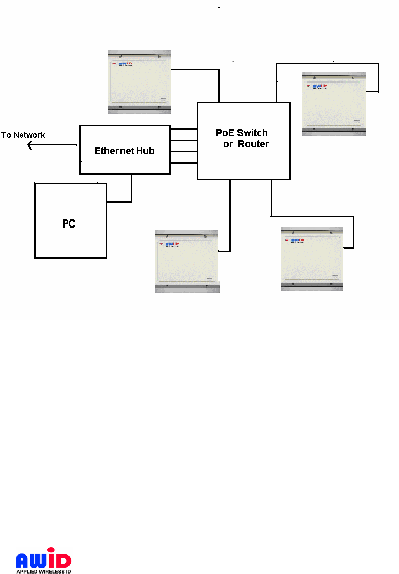
AWID PROPRIETARY
Figure 5 Four MPR-2010AN/BN Networked via PoE Switch/Router
Page 20 12/21/2004
AWID PROPRIETARY
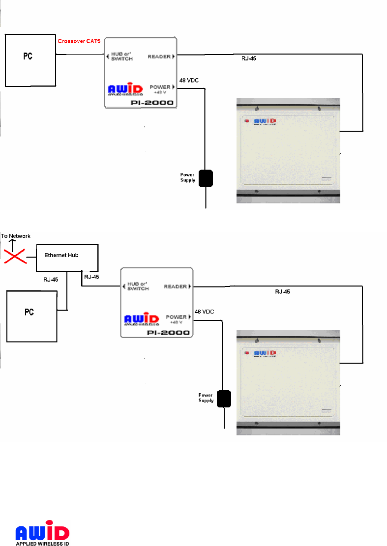
6.2. LOCAL SET UP DIAGRAM
Figure 6 Local Set Up without Ethernet Hub
Figure 7 Local Set Up with an Ethernet Hub