Applied Wireless Identifications Group MPR1710 Multi-Protocol RFID (MPR) Module User Manual 1
Applied Wireless Identifications Group Inc. Multi-Protocol RFID (MPR) Module 1
Users Manual
MPR-1710 - 1 - 6/19/2008
SENTINEL-SENSE MPR-1710
Installation & Operation Manual-041361

MPR-1710 - 2 - 6/19/2008
COPYRIGHT ACKNOWLEDGEMENTS
The contents of this document are the property of Applied Wireless Identifications Group, Inc.
(AWID) and are copyrighted. All rights reserved. Any reproduction, in whole or in part, is
strictly prohibited. For additional copies of this document please contact:
AWID
18300 Sutter Blvd
Morgan Hill, CA 95037
http://www.AWID.com
The information contained herein has been carefully checked and is believed to be accurate,
no responsibility is assumed for inaccuracies. AWID reserves the right to make changes
without prior notice. This document is not covered by any warranty either expressed or
implied. Any comments, corrections or additions to the contents of this document should be
directed to AWID at the above address.
Copyright 2006 AWID, Printed in USA.
All other trademarks are the property of their respective owners.
C AUTION:
Reader should be positioned so that personnel in the area for prolonged periods may
safely remain at least 20 cm in an uncontrolled environment from the reader’s surface.
Observe FCC OET Bulletin 56 “Hazards of radio frequency and electromagnetic fields” and
Bulletin 65 “Human exposure to radio frequency electromagnetic fields.”

MPR-1710 - 3 - 6/19/2008
Table of Contents
REVISION HISTORY .......................................................................................................4
1 INTRODUCTION.......................................................................................................5
1.1 Special Features................................................................................................5
2 SPECIFICATIONS ....................................................................................................6
2.1 Channel Frequency Table..................................................................................6
2.2 Connector Pin Assignment.................................................................................6
2.3 Measuring Read Distance..................................................................................7
3 INSTALLATION & OPERATION GUIDELINES .......................................................8
3.1 General Wiring Requirements............................................................................8
3.2 Wiring Diagrams ................................................................................................8
4 INSTALLATION PROCEDURE................................................................................9
4.1 Parts List............................................................................................................9
4.2 Preparation for Installation .................................................................................9
4.2.1 Bench Top Verification................................................................................9
5 SOFTWARE PROGRAMMING AND SYSTEM OPERATION NOTES...................10
5.1 System Operation ............................................................................................10
5.1.1 Running a Custom Software Application or the AWID Demo Program.....10
5.1.2 Operating Modes ......................................................................................10
5.2 Users Note.......................................................................................................10
6 MPR SERIAL COMMUNICATION PROTOCOL.....................................................11
NOTE: READ AND USE THIS MANUAL.
NOTE: FAILURE TO FOLLOW THE INSTALLATION GUIDE MAY RESULT IN
POOR PERFORMANCE OR EVEN CAUSE PERMANENT DAMAGE TO THE
READER, THUS VOIDS THE PRODUCT WARRANTY.

MPR-1710 - 4 - 6/19/2008
REVISION HISTORY
Version
No.
Revised
By
Date Sections
Affected
Remarks
0.1 E. Wei 3/2008 All Initial version

MPR-1710 - 5 - 6/19/2008
1 INTRODUCTION
AWID's Sentinel-Sense MPR-1710 is a Radio Frequency IDentification (RFID) reader
module with RS-232 and USB I/O interface that works with most leading passive UHF
passive tags. The reader module comes with a unique combination of long read range,
small size (credit card) and low power consumption. Its primary applications are access
control, asset management and tracking, and fleet management applications.
The MPR-1710 reader modules are delivered with firmware version US0-211h1-xx.yy.00.
In order to operate an MPR-1710 you will need the following:
PC running Windows
1
2000 or higher, CD-ROM drive, USB and/or RS-232 serial
port.
Host software (AWID’s demo software or your own custom software)
1.1 SPECIAL FEATURES
• UHF Multi-Protocol: ISO-18000-6 Type B/C, EPC Class 1 Gen 2
• Thin passive tags with long-range performance
• RS-232 and USB outputs
•
1
Though MPR-1710 can also be controlled from a non-Windows programming platform, AWID demo and
FW upgrade programs are applications to run in Windows.

MPR-1710 - 6 - 6/19/2008
2 SPECIFICATIONS
Input voltage +5.225 VDC to +5.775 VDC
Input current 1.5 A (5.5 V) typical
Protocol language ISO-18000-6 Type B/C, EPC Class 1 Gen 2
Read range Depends on type & size of labels used
Output power +24 dBm max
Transmit frequency 902.75-927.25 MHz
Receiver frequency 902.75-927.25 MHz (Amplitude Modulated)
Hopping channels 50 Channels
Channel spacing 500 kHz
Hopping sequence Pseudo random
Operating temperature range -30° C to +65° C (-22° F to 149° F)
Output data formats 3V TTL Serial & USB
I/O Connector 10-pin ZIF
Dimension 2”x3.25”x0.25
2.1 CHANNEL FREQUENCY TABLE
Frequency range: 902.75 ~ 927.25 MHz
Minimum number of frequency channels: 50
CH
902~928
MHz
CH
902~928
MHz
CH
902~928
MHz
CH
902~928
MHz
CH
902~928
MHz
0 902.75 MHz
10 907.75 MHz
20 912.75 MHz
30 917.75 MHz
40 922.75 MHz
1 903.25 MHz
11 908.25 MHz
21 913.25 MHz
31 918.25 MHz
41 923.25 MHz
2 903.75 MHz
12 908.75 MHz
22 913.75 MHz
32 918.75 MHz
42 923.75 MHz
3 904.25 MHz
13 909.25 MHz
23 914.25 MHz
33 919.25 MHz
43 924.25 MHz
4 904.75 MHz
14 909.75 MHz
24 914.75 MHz
34 919.75 MHz
44 924.75 MHz
5 905.25 MHz
15 910.25 MHz
25 915.25 MHz
35 920.25 MHz
45 925.25 MHz
6 905.75 MHz
16 910.75 MHz
26 915.75 MHz
36 920.75 MHz
46 925.75 MHz
7 906.25 MHz
17 911.25 MHz
27 916.25 MHz
37 921.25 MHz
47 926.25 MHz
8 906.75 MHz
18 911.75 MHz
28 916.75 MHz
38 921.75 MHz
48 926.75 MHz
9 907.25 MHz
19 912.25 MHz
29 917.25 MHz
39 922.25 MHz
49 927.25 MHz
Table 1 Channel Frequency Table for MPR-1710
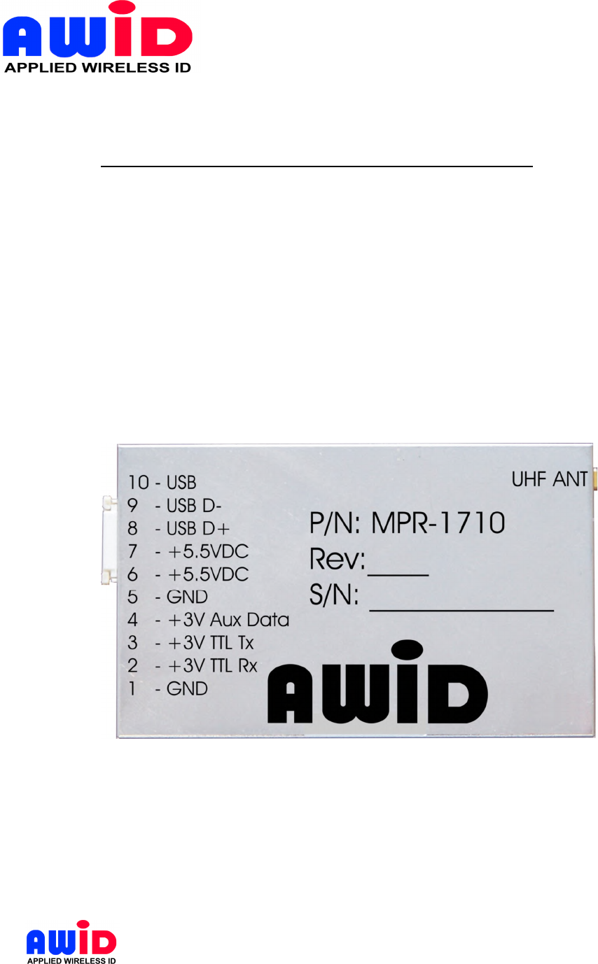
2.2 CONNECTOR PIN ASSIGNMENT
Pin Function Pin Function
1 USB 6 GND
2 USB D- 7 +3V Aux Data
3 USB D+ 8 +3V TTL Rx
4 +5.5 V 9 +3V TTL Tx
5 +5.5 V 10 GND

MPR-1710 - 7 - 6/19/2008
2.3 MEASURING READ DISTANCE
Make sure you know the tag types. For certain readers and tags, user must also be
mindful of the tag’s orientation and the reader’s antenna orientation, what mounting
surface the tags are designed for and how the tags are supposed to be mounted. Any
departure from its intended purpose will drastically affect the reader’s ability to energize
the tag and its read range.
When measuring the reader’s read range, make sure that the tag is properly oriented to
the reader antenna, and for optimum performance, be sure the operator’s finger is not
within three (3) inches of the tag’s antenna surface.
MPR-1710 - 8 - 6/19/2008
3 INSTALLATION & OPERATION GUIDELINES
For ease of explanation, MPR reader in this section refers to an RFID device that
consists of MPR-1710 and a high performance circular polarized antenna inside a
splash proof, UV stabilized housing case. The module should be installed on a heat
sink. Example of a heat sink could be an aluminum plate of size 8”x8”x0.1” exposed to
convection air flow. The screws at the bottom of module shall be used for mounting the
module on the heat sink.
3.1 GENERAL WIRING REQUIREMENTS
All the MPR reader wiring should be continuously shielded. AWID recommends using
#24 AWG up to #22 AWG, longer distances and higher current consumption on the
power supply line will require larger gauge wires.
TABLE 3.4-1: Data Line’s Wiring Requirement
WIRE SIZE #22 AWG (0.6 mm Dia.) #24 AWG (0.5 mm Dia.)
RS-232 50 ft (15 meters) 50 ft (15 meters)
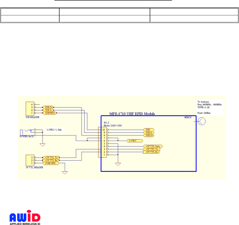
3.2 WIRING DIAGRAMS
See section 2.2 for pin assignment for the RS-232 connector of MPR-1710.
The MPR RS-232 interface is a short distance serial interface, a full command set for
the standard serial interface is not necessary, therefore only transmit, receive and
ground wires are used. Sense input is an enable input, which is traditionally used to
activate the RF energy of the reader and to start the read functions.

MPR-1710 - 9 - 6/19/2008
4 INSTALLATION PROCEDURE
This section provides installation and operation information for MPR-1710 reader modules.
4.1 PARTS LIST
Verify that all items listed below are present before starting the installation.
o Sentinel-Sense MPR-1710 Qty=1
o Documentation and command demo program CD Qty=1
4.2 PREPARATION FOR INSTALLATION
Familiarize yourself with the connectors and pin out assignment of each I/O connectors.
4.2.1 Bench Top Verification
It is always a good idea to verify system operation before committing to a full-scale
installation. The following are the necessary steps to test the reader’s operation in a
static environment.
Connect MPR-1710 to the RS-232 or USB port of a PC
Connect the power jack from the wall plug power supply to reader module
Power up PC
Install demo software on PC
Activate demo software and verify performance of the reader.
Select a COM port in program window then click “Connect”. Follow with some
commands.

MPR-1710 - 10 - 6/19/2008
5 SOFTWARE PROGRAMMING AND SYSTEM OPERATION NOTES
5.1 SYSTEM OPERATION
5.1.1 Running a Custom Software Application or the AWID Demo Program
If AWID Demo Program is not used, it is expected user will launch a Custom Software
Application developed using the MPR-1710 Protocol to issue commands to the MPR
reader/module as specified.
5.1.2 Operating Modes
Typical operating modes for MPR readers can be grouped into the following modes:
Search Mode
This mode is used when operator or user is not certain what family of tags is placed on
the items to be tracked. Since most tags are deterministic in nature, MPR reader must
cycle through each and every protocol, issue a protocol specific inquiry, to hail and to
wait for a response from tags of that specific protocol. Therefore, if there are many
different protocols, for an untrained observer, the reader response will appear sluggish.
Mixed Mode
This mode assumes the user is aware of the types of protocol in use, and furthermore, the
user made a determined effort to operate the reader in a mixed protocol mode. In this
mode, the user can decide how many and which specific protocols to be selected. Once
Mix Protocol Mode is selected, the reader will routinely cycle through each protocol, dwell
long enough for the reader to wait for a response and then move on to the next protocol. It
should be noted that in a mixed protocol mode, the tag must have sufficient time to
respond to the reader, and therefore, it can only be used on a conveyor belt arrangement,
with specific speed restrictions.
Single Protocol Mode
Single protocol is the normal mode of operation, where the protocol type is known and
many tags are expected to pass through the readers.
5.2 USERS NOTE
For System Integrators and/or Software Developers
System Integrators and/or software developers should get familiar with the MPR-1710
1712 Protocol specifications for developing applications that control an MPR-1710.
For Custom System Users
For custom system user, please refer to your host software user guide for information
regarding system and software operations
For Demo Software Users

MPR-1710 - 11 - 6/19/2008
If you are using the AWID RFID demonstration software application which is .NET based
with easy-to-follow GUI operations, simply select the COM port for which the device is
configured then click “Connect” should get you started.
6 MPR SERIAL COMMUNICATION PROTOCOL
See MPR-1710 Protocol Manual - 041377
Warning statements
This device complies with part 15 of the FCC rules.
Operation is subject to the following two conditions:
(1) this device may not cause harmful interference, and
(2) this device must accept any interference received, including interference that may cause
undesired operation.
Note: The manufacturer is not responsible for any radio or TV interference caused by
unauthorized modifications to this equipment. Such modifications could void the user’s authority
to operate the equipment.
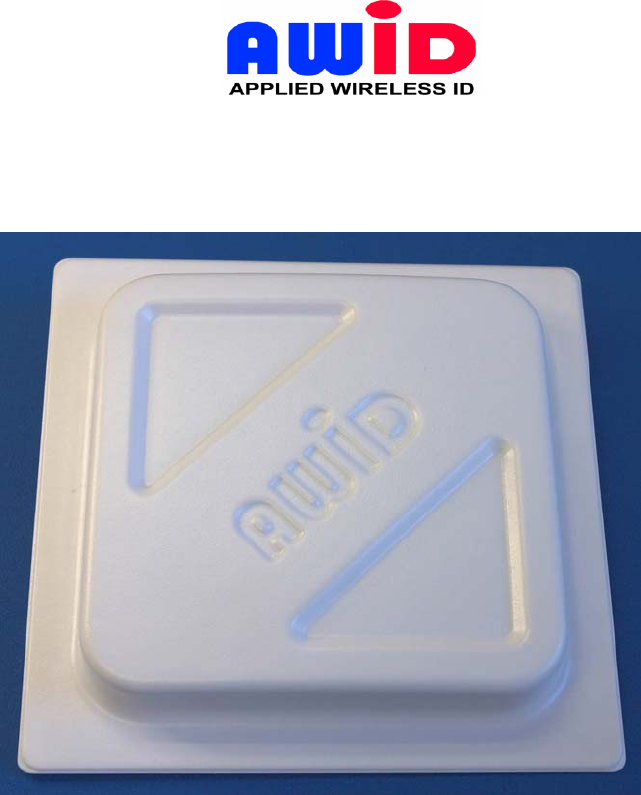
ANT-915CPS-A Rev.1.0 08/26/2006
Fig.1. Picture of the Circularly Polarized (RHCP) Patch Antenna
1. Specifications
1.1. Nominal frequency range from 900MHz to 930MHz
1.2. Max Gain = +5.70dBi
Min Gain = + 4.80dBi
1.3. The average Gain is +5.25dBi.
1.4. Circular polarized antenna - Polarization RHCP
ANT-915CPS-A
Page 2 08/26/2006
1.5. Axial ratio at boresight direction is less than 1.0dB (less than measurement
tolerance).
1.6.-3dB beam width, horizontal 63 degree;
-3dB beam width, vertical 63 degree;
1.7. Front to back ratio 14dB;
1.8. Input impedance 50 Ohm
1.9. Connector: Reverse Polarity TNC 50 Ohm.
1.10. VSWR less than 1.12 over frequency range 900–930 MHz
1.11. VSWR degradation in proximity 12” (0.3m) to the flat metal surface
VSWRmax=1.18 over frequency range 900–930 MHz
1.12. Maximum input power 5W.
1.13. Dimension 10"x10"x1.45" (260mm x 260mm x 37mm) without connector.
1.14. Weight: 1.0 and 1/16 lbs (0.482kg).
1.15. This antenna may be used for European frequency band 865 – 870 MHz and Japan
952 -954 MHz with some degradation of the gain and axial ratio.
VSWR less than 1.18 over frequency range 865 – 955 MHz
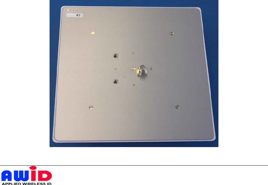
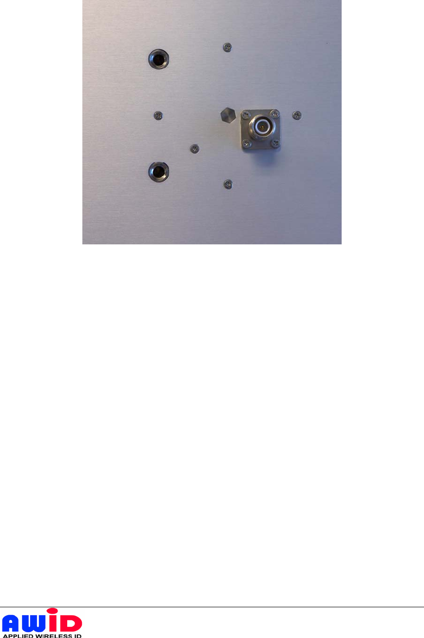
Fig.2. Back view of the Circularly Polarized Patch Antenna
ANT-915CPS-A
Page 3 08/26/2006
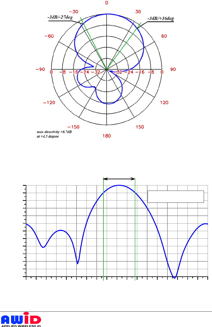
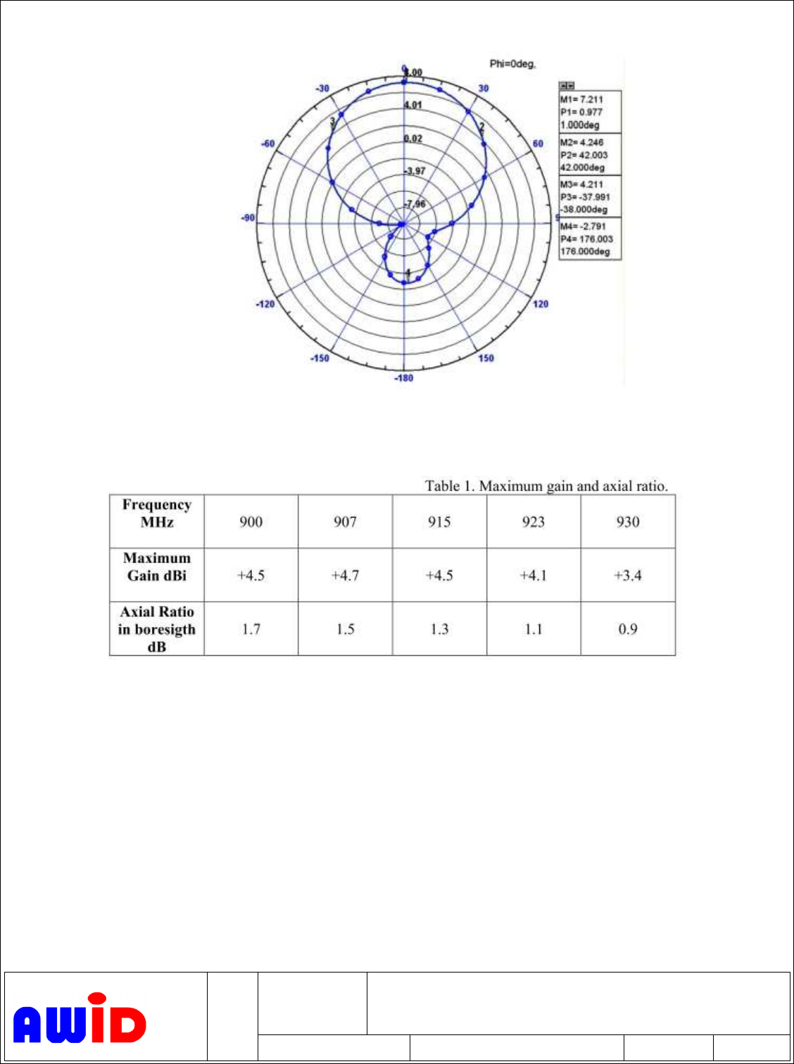
Fig.3. Normalized Logarithmic Directivity Eteta,
θ=0o…±180o, Φ=0o .(Polar diagram)
-180 -160 -140 -120 -100 -80 -60 -40 -20 0 20 40 60 80 100 120 140 160 180
T
e
t
a
d
e
g
r
ee
-36
-33
-30
-27
-24
-21
-18
-15
-12
-9
-6
-3
0
Normalized Directivity dB
-3dB Level Pattern Width 63
o
Maximum Directivity +8.7 dB
Fig.4. Normalized Directivity Eteta, Φ=0o
ANT-915CPS-A
Page 4 08/26/2006
Fig.5. Antenna Mounting
On the backside of the antenna, there are two mounting holes:
Thread ¼”-20 – diameter - ¼”; threads per inch - 20.
Depth – 3/8”.
Distance between holes – L1=1.97” (50mm).
APPLICATION REVISIONS
DASH
NO.
NEXT ASSY USED ON REV DESCRIPTION DATE APPROVED
Pre
PRELIMINARY ISSUE
7-31-2008 EH
Antenna Specifications:
Type: Circular Polarized Patch antenna
Antenna Gain: 4 dBi typical
Frequency Range: 902 to 928 MHz
Input Power: 4 Watts max
Input Impedance: 50 Ohm
Material: FR4 PCB
Connector: MMCX
Operational temperature:
-40°C to +60°C
Dimension: 5”x5”
AWID PROPRIETARY INFORMATION
CONTRRACT NO:
ALL PAGES ARE ON
ORIGINAL ISSUE (-) EXCEPT
AS NOTED ISSUED DATE
PREP BY:
Applied Wireless Identifications
APPLIED WIRELESS ID Monsey, NY USA
CHK BY:
REVIEW:
ENGR (PROJ):
Specification for ANT-915-CPS-C
APPVL (PPOJ):
SIZE
-
FSCM NO.
-
Doc. NO.
041390
REV
-
APPVL:
SCALE
2
FSCM NO.
July 31, 2008
DOC# 041390
ANT -915CPS-C page
APPLIED WIRELESS ID
SIZE
A
SCALE
AWID PROPRIETARY
REV -
Directivity:
Gain:

APPLICATION REVISIONS
DASH
NO.
NEXT ASSY USED ON REV DESCRIPTION DATE APPROVED
Pre
PRELIMINARY ISSUE
1-12-2005 DL
D Bandwidth correction
3-5-2007 EH
THIS DRAWING INCOMPLETE
WITHOUT ECN’S
None
AWID PROPRIETARY INFORMATION
CONTRRACT NO:
ALL PAGES ARE ON
ORIGINAL ISSUE (-) EXCEPT
AS NOTED ISSUED DATE
PREP BY: V. LTV
Applied Wireless Identifications
APPLIED WIRELESS ID Monsey, NY USA
CHK BY:
REVIEW:
ENGR (PROJ):
Design Specification for ANT-2010CP -- Serial
Interface Reader
APPVL (PPOJ):
SIZE
A
FSCM NO.
DWG NO.
041233
REV
D
APPVL: D Lee
SCALE

2
FSCM NO.
March 5, 2007
DWG #2010B-041233
MPR-2012 ANT page
APPLIED WIRELESS ID
SIZE
A
SCALE
AWID PROPRIETARY
SHEET 2
REV D
Revision Records:
Enter all revision records by stating “Paragraph Numbers," revision “From” and
“To”, “Revision Level” and “Time of Revision.”
Rev D:
4.1.5 Changed “
+/- 75 MHz” to “+/- 54 MHz”, document control# in footer corrected, March 5,
2007
3
FSCM NO.
March 5, 2007
DWG #2010B-041233
MPR-2012 ANT page
APPLIED WIRELESS ID
SIZE
A
SCALE
AWID PROPRIETARY
SHEET 2
REV D
1.0 Scope
This specification describes the electrical, mechanical and environmental requirements
for circular polarized UHF antenna, designed to work in conjunction with MPR-2010A or
MPR-2010B series of UHF RFID readers.
2.0 Applicable Documents
The following documents of the exact issue shown, form a part of this specification to the
extent specified herein. In the event of conflict between this document and the documents
referenced herein, the contents of this document shall prevail.
Specifications
Handbooks
Mil-HDBK-217E Reliability Prediction for Electronic Equipment
Standards
ISO-18000-6A/B ISO/IEC FCD 18000-6 (ISO/IEC JTC 1/SC 31/WG 4/SG 3)
EPC C1 & C0 EPC
TM
Tag Data Standards Version 1.1 Rev.1.22
EPC C1G2 EPC RFID Protocols Class-1 Generation-2 UHF RFID, V1.0.1
EPC 1.19 UCODE V1.19 (SL31C31 01) Functional Specification
Matrics Class 0 Tag “Write” Module Design Specification V1.1
Impinj Zuma (TBD)
3.0 Requirements
This RFID module shall transmit a CW or command signals to activate RFID tags in its
zone of surveillance and this RFID module shall also decoded the backscattered signal
from RFID tags.
3.1 Common Requirements
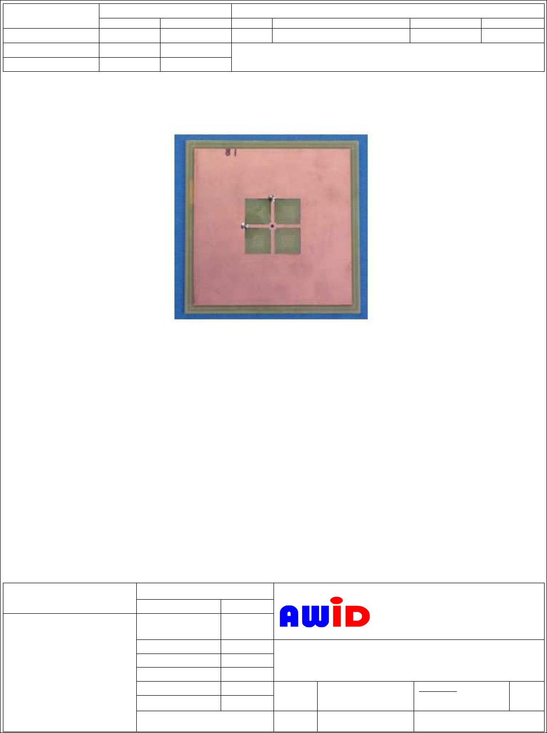
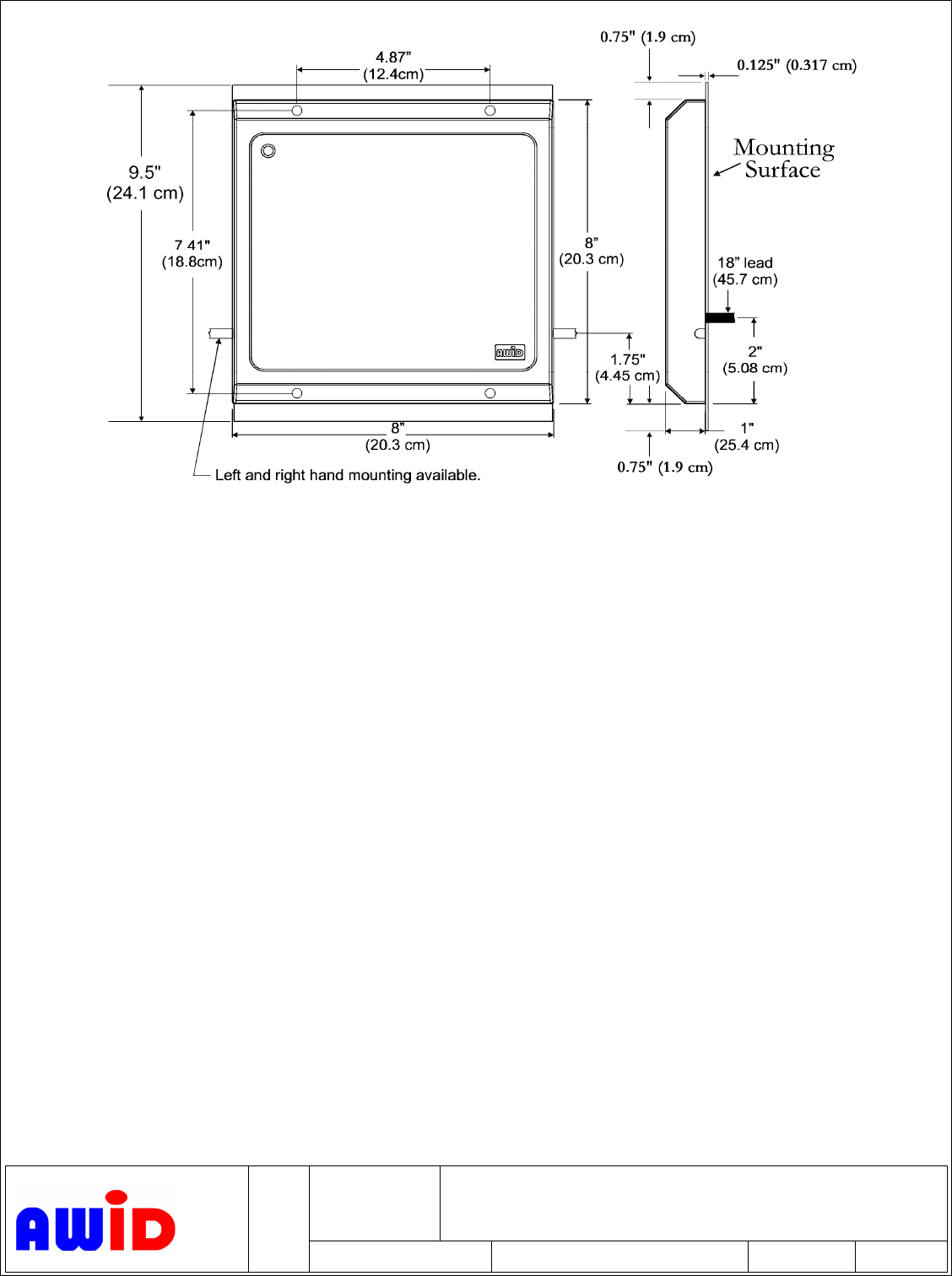
3.1.1 Form factor
The outline dimensions of the RFID antenna is
shown in the photo and Figure 1 is the mechanical dimension details of the antenna unit.
The antenna unit shall measured 8x9.5x1.0 inches.
4
FSCM NO.
March 5, 2007
DWG #2010B-041233
MPR-2012 ANT page
APPLIED WIRELESS ID
SIZE
A
SCALE
AWID PROPRIETARY
SHEET 2
REV D
Note: remove cables and add SMA antenna
Figure 1, Mechanical Dimensions
3.1.2 Weight
This RFID module shall weigh less than 24 oz. (0.7 kg)
3.1.3 Power Supply and Consumption
N/A
3.1.4 Multi-protocol operations
Protocol agnostic.
3.2 Environmental Characteristics
3.2.1 General
This RFID module is intended for use in a fixed and/or mobile
environment.
3.2.2 Cooling
Not required.
3.2.3 Temperature Change
-35 ºC to +70 ºC

5
FSCM NO.
March 5, 2007
DWG #2010B-041233
MPR-2012 ANT page
APPLIED WIRELESS ID
SIZE
A
SCALE
AWID PROPRIETARY
SHEET 2
REV D
3.2.4 Humidity
The RFID module shall withstand the following humidity extremes:
Minimum -- 0% RH
Maximum -- 95% RH
3.2.5 Random Vibration -- TBD
3.2.6 Shock -- TBD
3.3 Electromagnetic Compatibility
TBD
3.4 Reliability Requirement
3.4.1 Component Selection -- TBD
3.4.2 De-Rating -- AWID’s component de-rating guide.
3.4.3 MTBF TBD
Ground, Sheltered Benign
4.0 Antenna Electrical Specification
4.1 Frequency Characteristics
4.1.1 Operating Frequency -- 902 to 928 MHz center frequency
4.1.2 Gain -- 5.08 dB typical, 5.59 dB maximum
4.1.3 VSWR – 1.2:1 from 902 to 928 MHz
4.1.4 3-dB Pattern -- +/- 33º of free space pattern
4.1.5 3-dB Bandwidth -- +/- 54 MHz
4.1.6 Polarization -- Right hand or Left hand pattern
4.1.7 H/V Differential -- 0.5 dB
4.1.8 Front/Back Ratio -- 15 dB
4.1.9 Power Capability -- 5 Watts max.
4.1.10 Regional Code -- US – 902 to 928 MHz
China – 917 MHz (experimental)
Taiwan – 922 to 928 MHz
Singapore – 923 to 925 MHz
Koera (FHS) – 910 to 914 MHz
Korea (LBT) – 908.5 to 914 MHz
Australia – 918 to 926 MHz

6
FSCM NO.
March 5, 2007
DWG #2010B-041233
MPR-2012 ANT page
APPLIED WIRELESS ID
SIZE
A
SCALE
AWID PROPRIETARY
SHEET 2
REV D
4.1.11 Radiation Pattern -- See Figure 2
0.15 00.25 0.5
0.75
R
0
Distance
(R)
Width( W)
W (0.72R)
4.2 Interface with External Systems
4.2.1 Input Connector -- SMA (Reverse sex)
5.0 Marking
Antenna shall be market with part number, hardware revision level and serial number.
6.0 Configuration Control