Applied Wireless Identifications Group MR1824 Sentinel-Prox MR-1824 User Manual manual
Applied Wireless Identifications Group Inc. Sentinel-Prox MR-1824 manual
UserManual.wiki
>
Applied Wireless Identifications Group
>
MR1824 User Manual
>
User Manual
Contents
1.
User Manual
2.
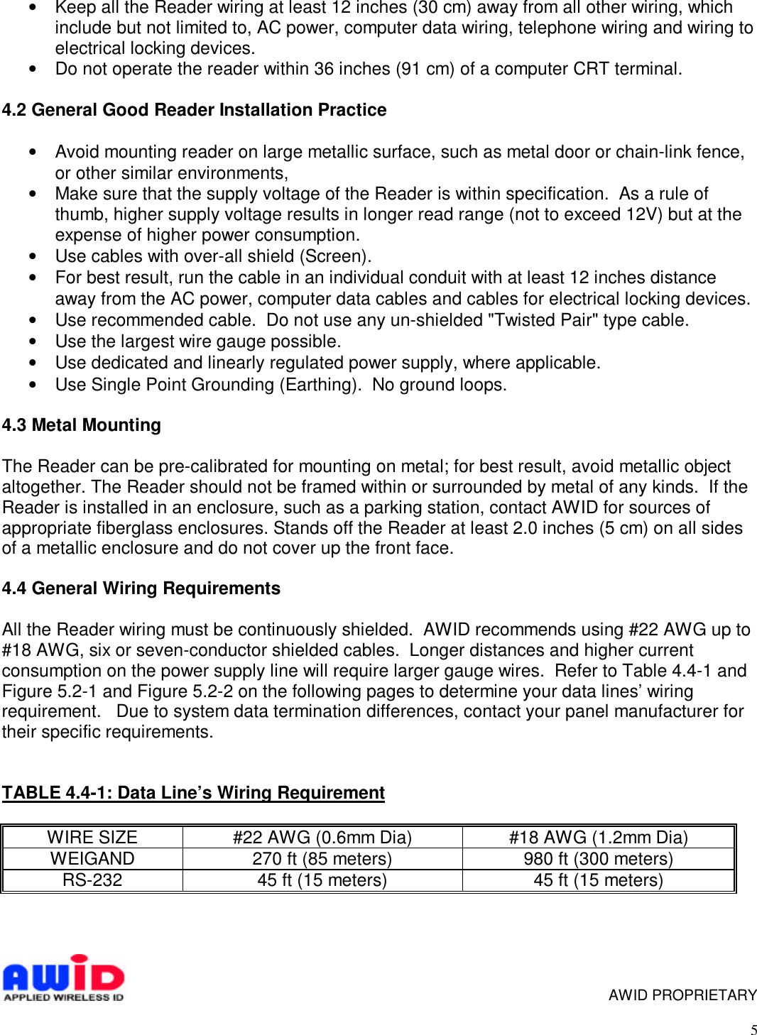
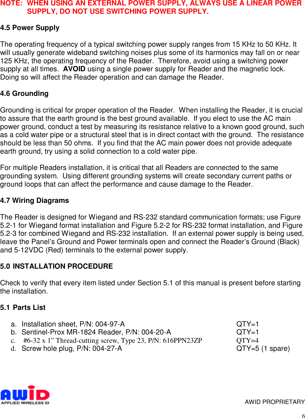
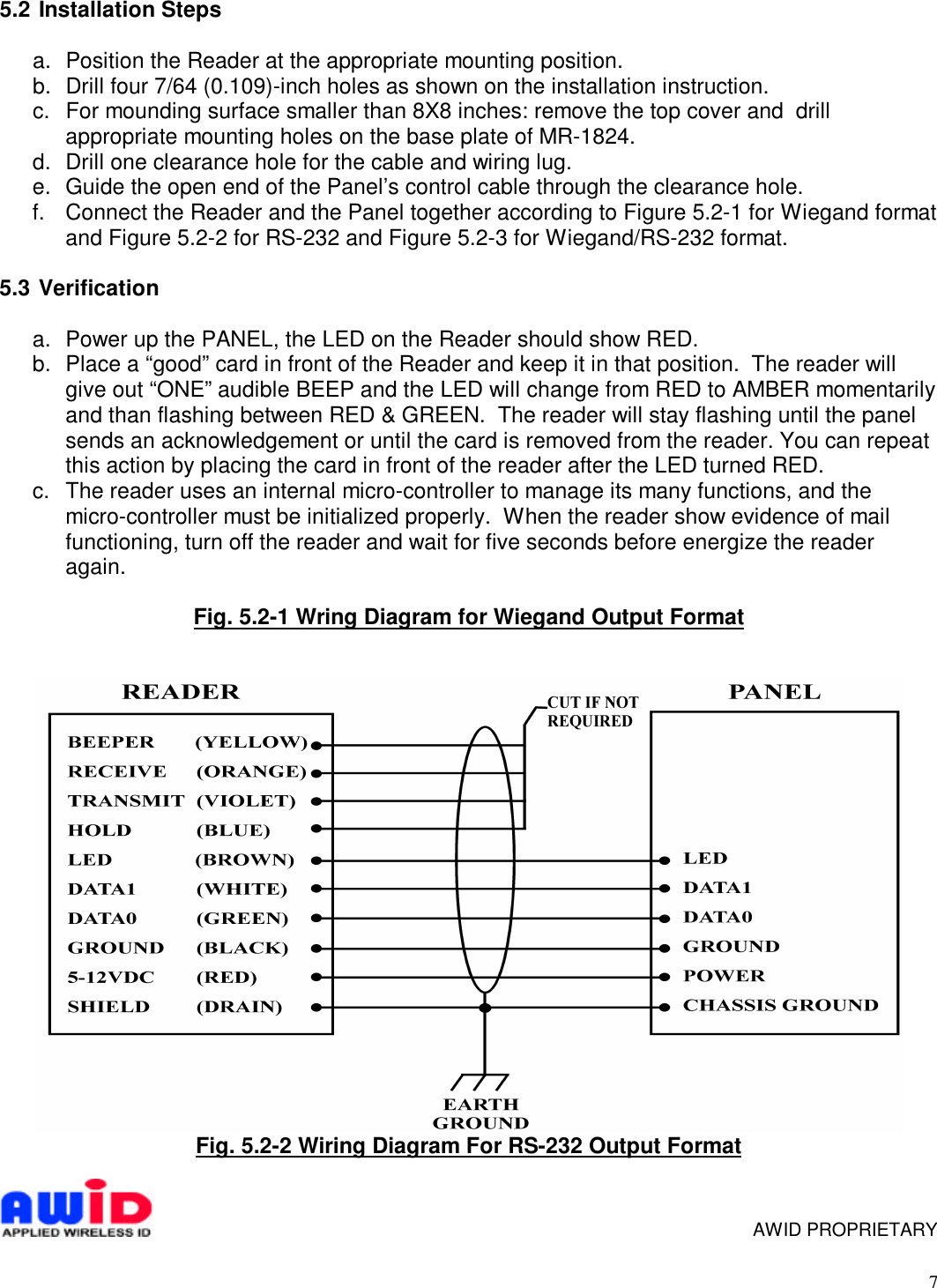
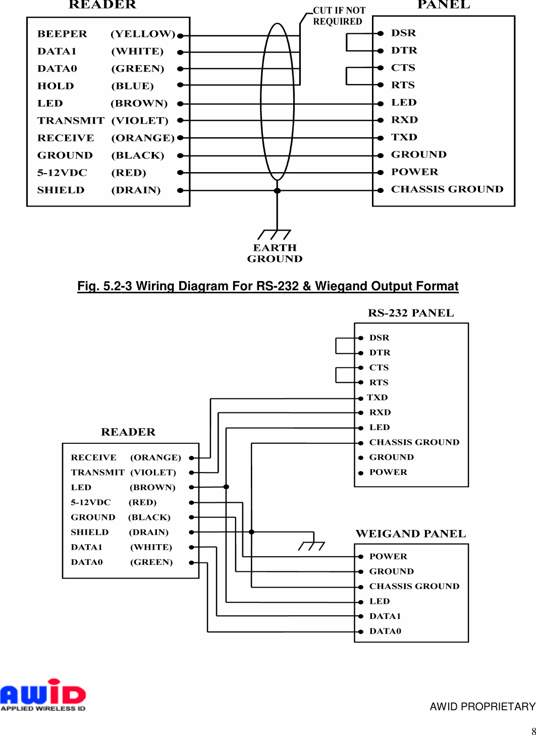
Installation Manual
User Manual
Navigation menu
Upload a User Manual
Namespaces
Wiki Guide
HTML
PDF
Info
Views
User Manual
Discussion / Help
Navigation