Applied Wireless Identifications Group MR1824 Sentinel-Prox MR-1824 User Manual manual
Applied Wireless Identifications Group Inc. Sentinel-Prox MR-1824 manual
Contents
- 1. User Manual
- 2. Installation Manual
User Manual
1
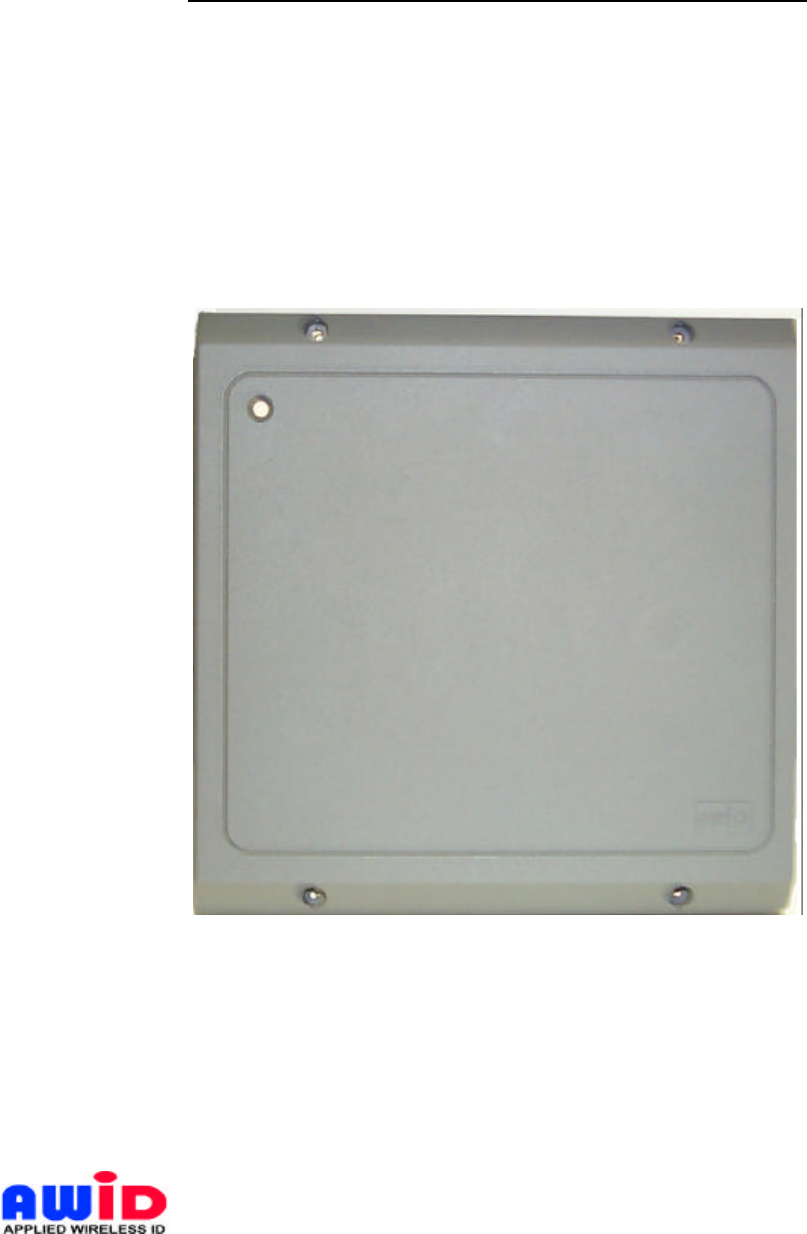
SENTINEL-PROX MR-1824
MID-RANGE PROXIMITY READER
Installation & Operation Manual - 004-98-A
PICTURE
Your best option for Proximity Access Control
Last Update: April 9, 1999
Applied Wireless Identifications Group, Inc.

2
Table of Contents
1.0 Introduction………………………………………………………………………Page 3
1.1 General Description..…………………………………………………….. 3
1.2 Special Features……………………………………………………….… 3
1.3 Suggested Applications……………………………………….…………. 3
2.0 Principal of Operation…………………………………………………………… 3
3.0 Specifications……………………………………………………………………. 4
3.1 Measuring Read Distance…..……………..…………………….………. 4
4.0 Preparation for Installation………….…………………………………………... 4
4.1 Site Survey………………………………………………………………. 4
4.2 General Good Reader Installation Practice……………………………… 5
4.3 Metal Mounting…………………………………………………………. 5
4.4 General Wiring Requirements……………………...…………………... 5
4.5 Power Supply…………………………………………………………… 6
4.6 Grounding……………………………………………………………….. 6
4.7 Wiring Diagrams………………………………………………………... 6
5.0 Installation Procedure…………………………………………….……………... 6
5.1 Parts List………………………………………………………………… 6
5.2 Installation Steps………………………………………………………… 7
5.3 Verification……………………………………………………………… 7
5.4 Mounting………………………………………………………………… 9
6.0 Warranty…………………….………………………………………….……….. 9
7.0 Return Material Authorization (RMA)……………………………………..…… 9
8.0 Troubleshooting……….………………………………………………….……... 9
9.0 Patents and Approvals…………………………………………………….……... 10
NOTE: READ AND USE THIS MANUAL.
FAILURE TO DO SO MAY RESULT IN POOR READER PERFORMANCE OR EVEN
PERMANENT DAMAGE TO READER, WHICH COULD VOID THE READER
WARRANTY.
List of Table
Table 4.4-1: Data Line’s Wiring Distance Requirement…………………………….Page 5
List of Figures
Figure 5.2-1: Wiring Diagram for Wiegand Output Format…………….……………Page 7
Figure 5.2-2: Wiring Diagram for RS232 Output Format…………………………….. 8
Figure 5.2-3: Wiring Diagram for RS232 & Wiegand Output Format…….………….. 8
AWID PROPRIETARY

3
1.0 INTRODUCTION:
AWID's Sentinel-Prox MR-1824 Reader is one of the best performing Mid-Range Proximity
Readers in the industry. It has the unique combination of long read range with low power
consumption, and in some cases, the power supply in the access control panel is sufficient to
power the MR-1824. This Reader is pre-calibrated for mounting on metallic elbow stands with
simultaneous Wiegand and RS-232 outputs. Its primary applications are Access Control in ADA
compliance applications where wheelchair bound persons can activate the entrance control at a
convenient distance.
1.1 General Descriptions:
• Wall mount or pedestal mount reader
• Indoor or outdoor installation • LED visual indicator
• Audio/visual feedback
1.2 Special Features:
• Simultaneous Access Control (Wiegand) and Time & Attendance (RS-232) outputs
• Pre-calibrated for mounting on metallic elbow stand with minimum impact on read range
• Permanently sealed electronics for indoor or outdoor applications
• UV stabilized plastic housing
1.3 Suggested Applications
• Access Control
• Asset Management • Time & Attendance
• RFID
2.0 PRINCIPAL OF OPERATION
This Radio Frequency Identification (RFID) reader or proximity reader uses radio frequency to
identify, locate and track people and objects that carry the appropriate transponders. Proximity
reader can work in none line-of-sight situations and in darkness, bright sun light or through dirt,
grimes and smudges.
A typical proximity system consists of three components – an interrogator or a reader, a
transponder or a card and a data processing panel and/or computer combination. Most RFID
reader has an internal micro-controller, a transmitter, a receiver and a shared transmit/receive
antenna. The card is usually passive (without an internal battery) and consists of an antenna
and an RFID ASIC (Application Specific IC). During operation, the transmitter sends out an
electromagnetic wave to establish a zone of surveillance. When a card enters this zone, the
electromagnetic energy from the reader begins to energize the IC in the tag. Once the IC is
energized, it goes through an initialization process and begins to broadcast its identity. This
process utilizes a low energy back-scattering technology that selectively reflects or back-
scatters the electromagnetic energy back to the reader. The receiving circuits in the reader
senses and decodes this back-scattered signal and hence determines the identity of the tag.
AWID PROPRIETARY

4
3.0 SPECIFICATIONS
- Input voltage……………………………..+5V to +12V
- Input current……………………………...250 to 650 mA typical
- Read range:
Prox-Linc GR & CS………….…….Up to 19 inches (48 cm), 5V @ 250 mA peak
Prox-Linc CS & CS………………..Up to 25 inches (64 cm), 12V @ 650 mA peak
- Transmit frequency………………………125KHz (CW)
- Receiver frequency………………………125KHz (Amplitude Modulated)
- Operating temperature range…………...-30° C to +65° C
- Color……………………………………….Dark Gray or Beige
- Output formats available…………………Simultaneous Wiegand & RS-232 (Standard)
(Others are available upon request)
3.1 Measuring Read Distance
To measure the read range between Reader and card, grasp the card by the corner or near the
slot and move the card slowly toward the Reader, with the card surface parallel to the Reader,
until a BEEP occurs. The BEEP indicates that the Reader detects and reads the card. In order
to read again, the card must be fully withdrawn from the Reader’s read field and then re-
approached again. During normal operation, the card can be presented at any angle relative to
the Reader, however this will result in slight variation of read range.
Note: Do not "waved" the card in front of the Reader. "Waving" the card in front of the
Reader will cause diminishing read range.
NOTE: FAILURE TO FOLLOW THE INSTALLATION GUIDE MAY RESULT IN POOR
PERFORMANCE OR EVEN CAUSE PERMANENT DAMAGE TO THE READER.
THUS, VOIDING THE PRODUCT WARRANTY.
4.0 PREPARATION FOR INSTALLATION
4.1 Site Survey:
Always conduct a site survey before starting installation, avoid any possible sources of
interference. If the Reader is not installed properly, the performance will be degraded or more
seriously the Reader may be damaged. The following is a list of installation procedures that
should be followed during installation:
• Do not install the Reader in the vicinity where sources of broadband noise may exist.
Examples of broadband noise sources are motors, pumps, generators, DC-AC or AC-DC
converters, non-interruptible power supplies, AC switching relays, light dimmers, CRT's,
induction heater etc.
• Do not let the Reader wiring bundle together in one conduit with the AC power cables,
lock power, and other signal wiring.
AWID PROPRIETARY
5
• Keep all the Reader wiring at least 12 inches (30 cm) away from all other wiring, which
include but not limited to, AC power, computer data wiring, telephone wiring and wiring to
electrical locking devices.
• Do not operate the reader within 36 inches (91 cm) of a computer CRT terminal.
4.2 General Good Reader Installation Practice
• Avoid mounting reader on large metallic surface, such as metal door or chain-link fence,
or other similar environments,
• Make sure that the supply voltage of the Reader is within specification. As a rule of
thumb, higher supply voltage results in longer read range (not to exceed 12V) but at the
expense of higher power consumption.
• Use cables with over-all shield (Screen).
• For best result, run the cable in an individual conduit with at least 12 inches distance
away from the AC power, computer data cables and cables for electrical locking devices.
• Use recommended cable. Do not use any un-shielded "Twisted Pair" type cable.
• Use the largest wire gauge possible.
• Use dedicated and linearly regulated power supply, where applicable.
• Use Single Point Grounding (Earthing). No ground loops.
4.3 Metal Mounting
The Reader can be pre-calibrated for mounting on metal; for best result, avoid metallic object
altogether. The Reader should not be framed within or surrounded by metal of any kinds. If the
Reader is installed in an enclosure, such as a parking station, contact AWID for sources of
appropriate fiberglass enclosures. Stands off the Reader at least 2.0 inches (5 cm) on all sides
of a metallic enclosure and do not cover up the front face.
4.4 General Wiring Requirements
All the Reader wiring must be continuously shielded. AWID recommends using #22 AWG up to
#18 AWG, six or seven-conductor shielded cables. Longer distances and higher current
consumption on the power supply line will require larger gauge wires. Refer to Table 4.4-1 and
Figure 5.2-1 and Figure 5.2-2 on the following pages to determine your data lines’ wiring
requirement. Due to system data termination differences, contact your panel manufacturer for
their specific requirements.
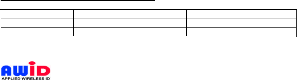
TABLE 4.4-1: Data Line’s Wiring Requirement
WIRE SIZE #22 AWG (0.6mm Dia) #18 AWG (1.2mm Dia)
WEIGAND 270 ft (85 meters) 980 ft (300 meters)
RS-232 45 ft (15 meters) 45 ft (15 meters)
AWID PROPRIETARY

6
NOTE: WHEN USING AN EXTERNAL POWER SUPPLY, ALWAYS USE A LINEAR POWER
SUPPLY, DO NOT USE SWITCHING POWER SUPPLY.
4.5 Power Supply
The operating frequency of a typical switching power supply ranges from 15 KHz to 50 KHz. It
will usually generate wideband switching noises plus some of its harmonics may fall on or near
125 KHz, the operating frequency of the Reader. Therefore, avoid using a switching power
supply at all times. AVOID using a single power supply for Reader and the magnetic lock.
Doing so will affect the Reader operation and can damage the Reader.
4.6 Grounding
Grounding is critical for proper operation of the Reader. When installing the Reader, it is crucial
to assure that the earth ground is the best ground available. If you elect to use the AC main
power ground, conduct a test by measuring its resistance relative to a known good ground, such
as a cold water pipe or a structural steel that is in direct contact with the ground. The resistance
should be less than 50 ohms. If you find that the AC main power does not provide adequate
earth ground, try using a solid connection to a cold water pipe.
For multiple Readers installation, it is critical that all Readers are connected to the same
grounding system. Using different grounding systems will create secondary current paths or
ground loops that can affect the performance and cause damage to the Reader.
4.7 Wiring Diagrams
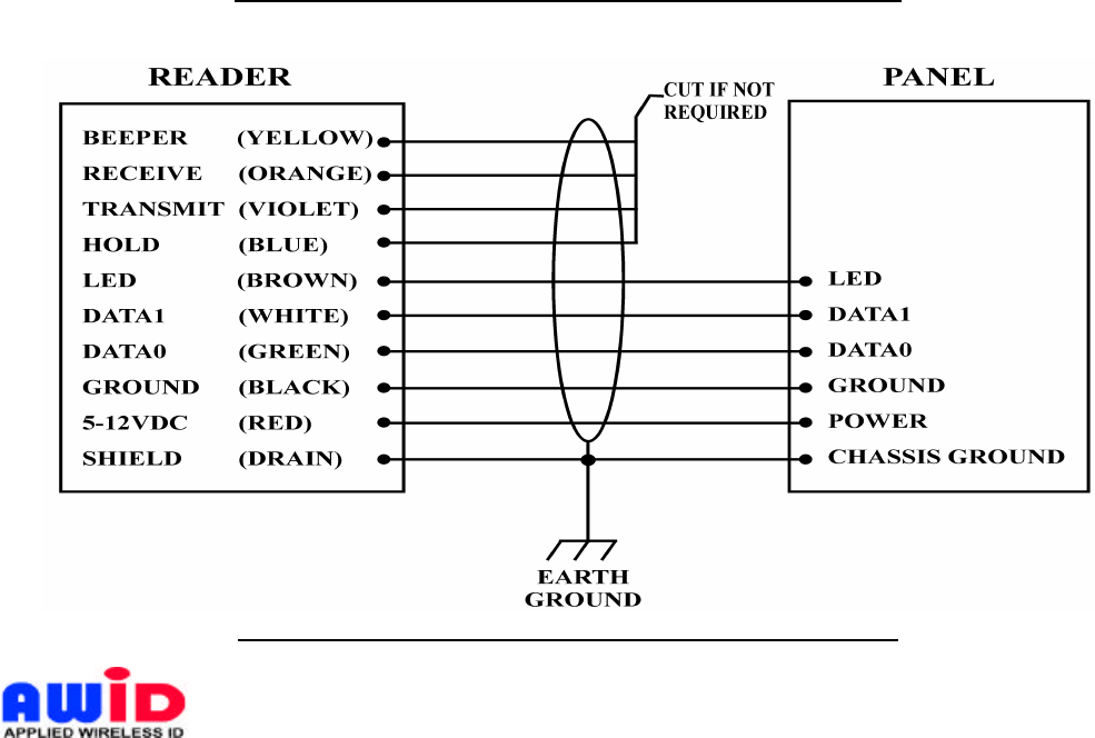
The Reader is designed for Wiegand and RS-232 standard communication formats; use Figure
5.2-1 for Wiegand format installation and Figure 5.2-2 for RS-232 format installation, and Figure
5.2-3 for combined Wiegand and RS-232 installation. If an external power supply is being used,
leave the Panel’s Ground and Power terminals open and connect the Reader’s Ground (Black)
and 5-12VDC (Red) terminals to the external power supply.
5.0 INSTALLATION PROCEDURE
Check to verify that every item listed under Section 5.1 of this manual is present before starting
the installation.
5.1 Parts List
a. Installation sheet, P/N: 004-97-A QTY=1
b. Sentinel-Prox MR-1824 Reader, P/N: 004-20-A QTY=1
c. #6-32 x 1” Thread-cutting screw, Type 23, P/N: 616PPN23ZP QTY=4
d. Screw hole plug, P/N: 004-27-A QTY=5 (1 spare)
AWID PROPRIETARY
7
5.2 Installation Steps
a. Position the Reader at the appropriate mounting position.
b. Drill four 7/64 (0.109)-inch holes as shown on the installation instruction.
c. For mounding surface smaller than 8X8 inches: remove the top cover and drill
appropriate mounting holes on the base plate of MR-1824.
d. Drill one clearance hole for the cable and wiring lug.
e. Guide the open end of the Panel’s control cable through the clearance hole.
f. Connect the Reader and the Panel together according to Figure 5.2-1 for Wiegand format
and Figure 5.2-2 for RS-232 and Figure 5.2-3 for Wiegand/RS-232 format.
5.3 Verification
a. Power up the PANEL, the LED on the Reader should show RED.
b. Place a “good” card in front of the Reader and keep it in that position. The reader will
give out “ONE” audible BEEP and the LED will change from RED to AMBER momentarily
and than flashing between RED & GREEN. The reader will stay flashing until the panel
sends an acknowledgement or until the card is removed from the reader. You can repeat
this action by placing the card in front of the reader after the LED turned RED.
c. The reader uses an internal micro-controller to manage its many functions, and the
micro-controller must be initialized properly. When the reader show evidence of mail
functioning, turn off the reader and wait for five seconds before energize the reader
again.
Fig. 5.2-1 Wring Diagram for Wiegand Output Format
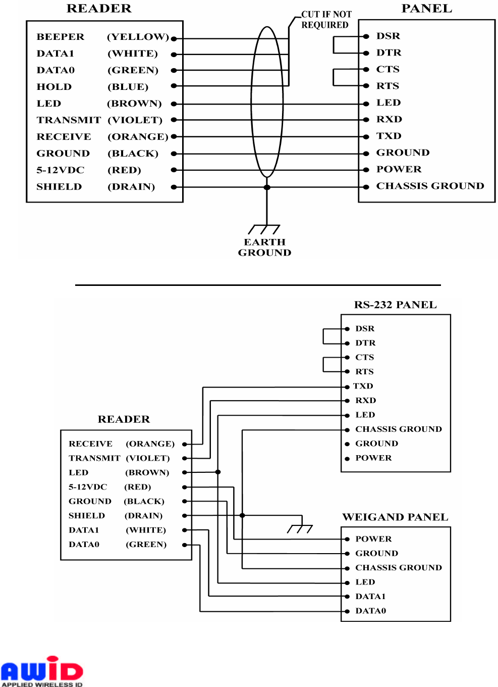
Fig. 5.2-2 Wiring Diagram For RS-232 Output Format
AWID PROPRIETARY
8
Fig. 5.2-3 Wiring Diagram For RS-232 & Wiegand Output Format
AWID PROPRIETARY

9
5.4 Mounting
a. Checks to ensure all connections are secured. Feed all wires through the cable access
hole to the rear of mounting plate.
b. Mount the Reader with the #6-32x1” Thread-cutting screw, Type 23 (Item c on Parts List).
c. Insert the Screw hole plug (Item d on Parts List) into the screw clearance holes to
conceal the screws. Note: screw hole plugs are designed for one-time use only!
Once the plug are seated, they can not be removed without damaging the plugs.
6.0 WARRANTY
AWID’s products are warranted to the original purchaser to be free of defects in material and
workmanship for the life of the product. Any tampering or modification to the product will void
this product warranty. AWID does not warrant any product as to its merchantability or suitability
of use. AWID's sole and complete responsibility under this warranty is expressly limited to
repair or replacement of the warranted product.
7.0 RETURN MATERIAL AUTHORIZATION (RMA)
AWID monitors and tracks the life cycle performance of our product through our RMA system.
All customers must obtain a RMA number from AWID Customer Service Department prior to
returning the merchandise. After the customer provides AWID Customer Service Department
with the serial number and a description of the returning item, a RMA number will be issued.
This RMA number must be clearly marked on the outside of the returned package and
noted on the paperwork attached to the returned merchandise.
When obtaining a RMA number for RFID tags, please provide AWID Customer Service
Department with the serial numbers, card identification numbers, facility codes and etc. If exact
duplicates of returned cards or tags are requested, the customer must provide AWID with the
numbers needed. AWID reserves the option to replace or repair returned merchandise.
Items returned to AWID without the proper authorization will be returned to the originators at
their own expense.
8.0 TROUBLESHOOTING
This unit, if not installed in strict compliance with AWID’s installation instructions, may not
function to specifications. Use the checklist below to identify the problem:
• Is the card valid and working? - Try some different cards!
• Is the reader wired correctly? - RED-BLK :5-12V, reader should work
• Is the unit grounded properly? - DRAIN-EARTH: less than 50 Ohms
• Is the card presented correctly? - Card face parallel to reader face
• Is a power supply correct? - No switching power supply please!
• Is reader voltage/current correct? - 5-12V @ 40-100mA typical
• Is the environment free from electromagnetic interference? - Run cable away from other
data carrying cables, reader away from electromagnetic interference sources!
AWID PROPRIETARY

10
When troubleshooting, try to identify the source of the problem to a unit level. “Is the problem
from the panel?” Or “is the problem originated from the Reader? “ Maybe the problem “is the
power supply?”
All AWID’s readers will need only a power supply and a valid card to work properly. If the
reader is only connected with RED (+5-12V) and BLACK (Ground), the reader will BEEP and
momentarily turned AMBER, when a valid card is presented. If the Card stays within the reader
zone of surveillance, the LED on the reader will become flashing GREEN. When the card is
removed, the LED will return to RED, signifying it has returned to stand-by mode. When the
reader works according to the tests above, the reader is working properly.
Do not cycle the power supply ON and OFF in rapid succession. Each power has its unique
“decay” characteristics, turning the power supply ON and OFF in rapid succession can cause
the Microcontroller to lock-up, due to improper initialization. Always turn the power supply OFF
and count 10 seconds before turning ON again.
To check the validity of the output data in the absence of a panel, you will need to build a patch
cable between the reader and a PC. Call AWID’s technical support for details.
If problem persists, consult the system manufacturer. If problem is the reader, consult AWID’s
Technical Assistance Department. AWID help desk is opened from 8:00 AM to 8:00 PM
Eastern Standard Time, and can be reached by dialing 1-800-369-5533.
9.0 PATENTS AND APPROVALS
AWID products are covered by United States patent #5594384.
AWID logo is a registered trademark of Applied Wireless Identifications Group, Inc.
Where required, AWID’s products will be approved by the appropriate regulatory agencies:
U. S. Federal Communications Commission: Part 15
Underwriter Laboratory: UL 294
Designed to Comply with: CE, UL, VDE, BZT, DTI & PTT
Information To The User
This device complies with part 15 of the FCC Rules. Operation is subject to the following two
conditions: (1) this device may not cause harmful interference, and (2) this device must accept
any interference received, including interference that may cause undesired operation.
AWID PROPRIETARY