Arcade Gold Fishin Manual User
2015-03-23
User Manual: Arcade Gold Fishin Manual
Open the PDF directly: View PDF ![]() .
.
Page Count: 30
1
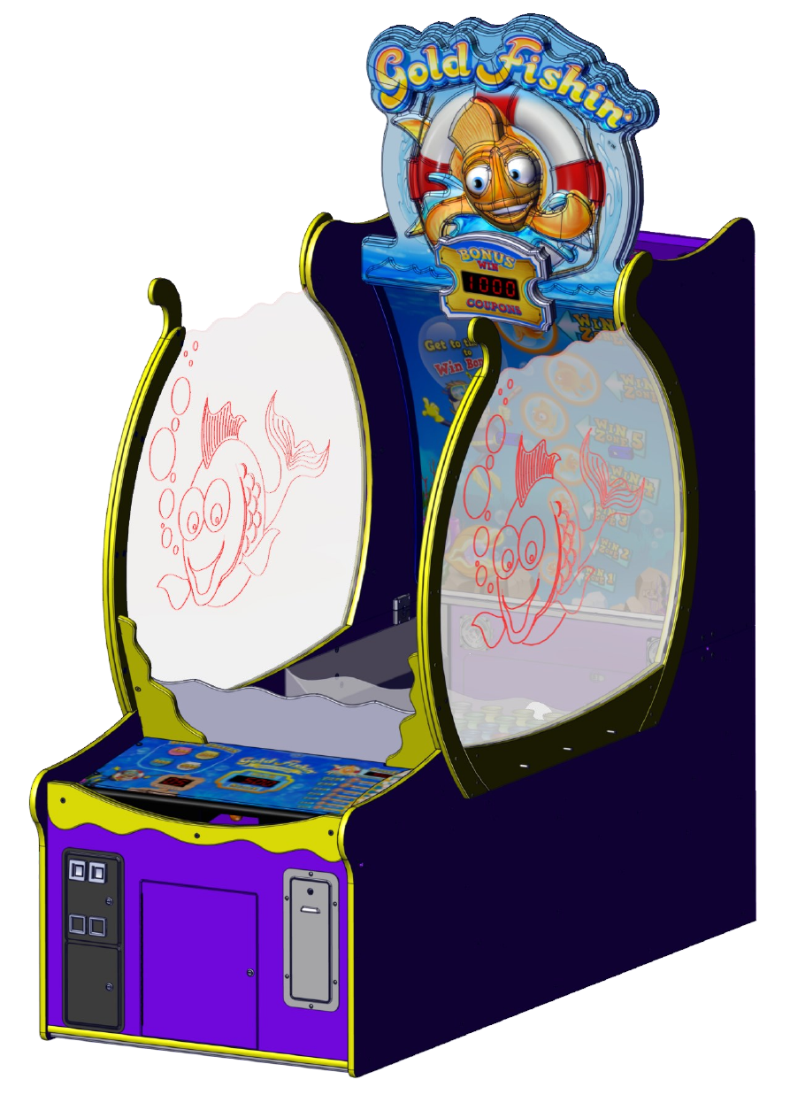
Gold Fishin’ Service Manual
Innovave Concepts In Entertainment, Inc.
2
Table of Contents
Safety and Warnings 3
Game Assembly
Assembly Check list 4
Fully disassembled Game setup instrucons 5
Assembled Game setup instrucons (Start on Step 15) 11
Mega Marquee 13
Changing Program Sengs 18
Program Opons 19
Suggested Sengs for Ticket Payout 20
Audits 21
Removing the Ball Ramp 22
Fish Bowl Removal 23
Accessing Sensors 24
Sensor Layout 25
Serial Port Diagnoscs 26
Rotary Diagnoscs 27
Ball Dispenser Motor Replacement 28
Spare Part List 29
Warranty 30
Rev B 2/6/2015
3
SAFETY AND WARNINGS BEFORE YOU BEGIN
WARNING: WHEN INSTALLING THIS GAME, A GROUNDED A.C. RECEPTACLE MUST BE USED.
FAILURE TO DO SO COULD RESULT IN INJURY TO YOURSELF OR OTHERS. FAILURE TO USE A
GROUNDED RECEPTACLE COULD ALSO CAUSE IMPROPER GAME OPERATION, OR DAMAGE TO
THE ELECTRONICS.
NOTE: THIS GAME IS INTENDED FOR INDOOR USE ONLY.
DO NOT DEFEAT OR REMOVE THE GROUNDING PRONG ON THE POWER CORD FOR THE SAME
REASON AS GIVEN ABOVE. USING AN IMPROPERLY GROUNDED GAME COULD VOID YOUR
WARRANTY.
HAVE A QUALIFIED ELECTRICIAN CHECK YOUR A.C. RECEPTACLE TO BE SURE THE GROUND IS
FUNCTIONING PROPERLY.
THIS GAME IS DESIGNED TO DISSIPATE STATIC ELECTRICITY THROUGH THE GROUNDING PLANE
OF THE GAME. IF THE A.C. GROUND DOES NOT WORK, THE GAME COULD DISCHARGE STATIC
ELECTRICITY THROUGH THE GAME CIRCUITRY, WHICH COULD CAUSE DAMAGE.
THE POWER SUPPLY IS NOT VOLTAGE ADJUSTABLE. TO OPERATE THE GAME AT VOLTAGES
OTHER THAN THOSE IT WAS DESIGNED FOR. PLEASE CONTACT OUR SERVICE DEPARTMENT FOR
VOLTAGE CONVERSION INFORMATION.
WARNING
DO NOT remove any of the components on the main board (e.g. compact flash and eproms) while the game
is powered on. This may cause permanent damage to the parts and the main board. Removing any main
board component part while powered on will void the warranty.
ALWAYS REMOVE POWER TO THE GAME, BEFORE ATTEMPTING ANY SERVICE,
UNLESS NEEDED FOR SPECIFIC TESTING. FAILURE TO OBSERVE THIS PRECAUTION
COULD RESULT IN SERIOUS INJURY TO YOURSELF OR OTHERS.
THIS GAME IS NOT SUITABLE FOR INSTALLATION IN AN AREA WHERE A WATER JET COULD BE
USED.
This appliance is not intended for use by persons (including children) with reduced physical, sensory or
mental capabilities, or lack of experience and knowledge, unless they have been given supervision or
instruction concerning use of the appliance by a person responsible for their safety. Children should be
supervised to ensure that they do not play with the appliance.
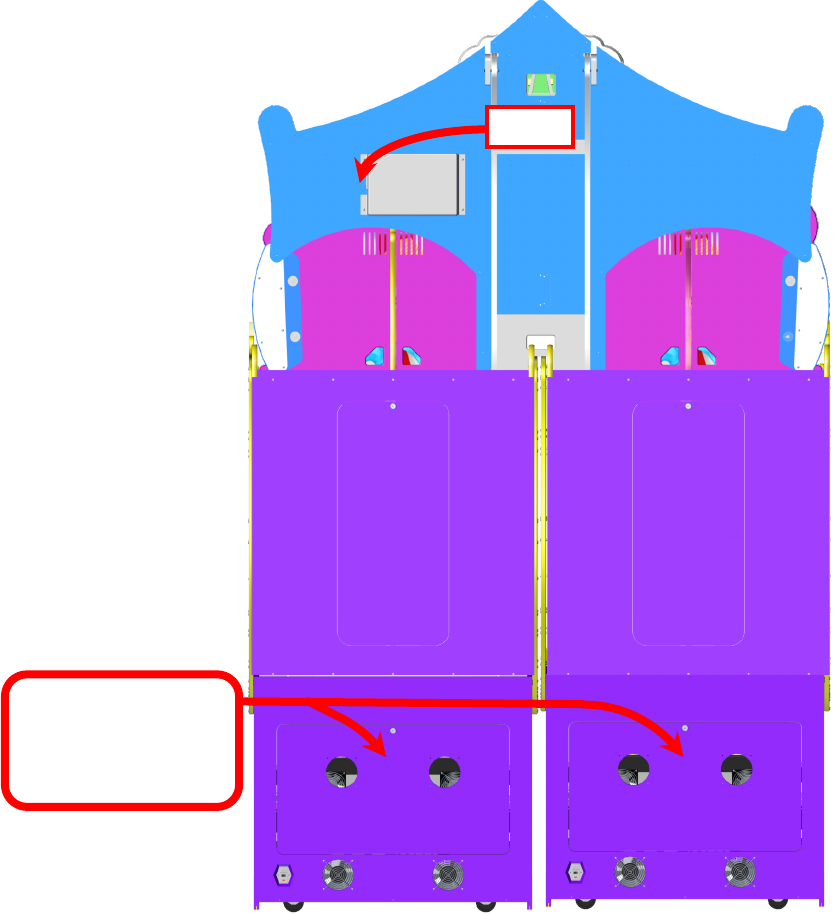
AC Power Information
The games main fuse is accessed through the back of the game at the power mod. Above the power cord is a small
panel that contains the main fuse.
The value of the fuse for 120 volt users is 8 AMPS at 250Volt type slow blow.
The value of the fuse for 230 volt users is 4 AMPS at 250Volt type slow blow.
4
OR
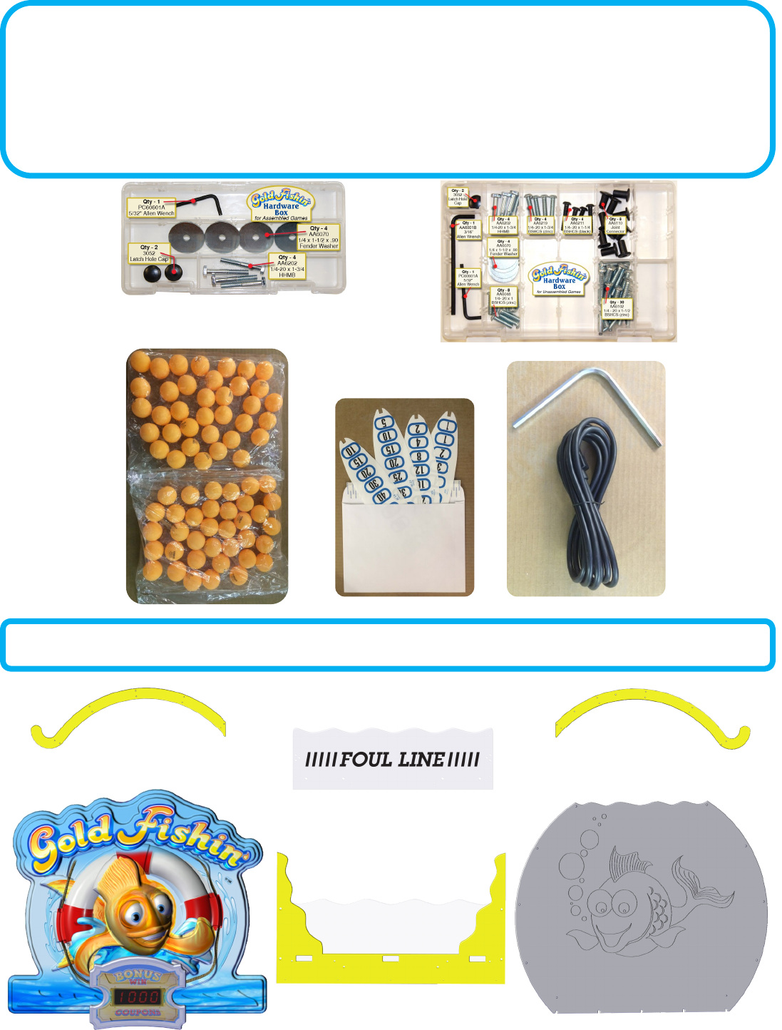
Your Game Should Include:
The game can be shipped assembled or disassembled. The hardware package included depends on how
the game was shipped. Assembled games need only the marquee installed so you can skip to step 15. If
you game included a Mega Marquee, please review the secon “Gold Fishin Mega Marquee Instrucons”
for a list of addional components that should have be included.
X’s 2
X’s 2
Fully disassembled games will have these items shown below in addion to the above items.
X’s 2
Might have rebound guard already
mounted.
Might be already mounted on
Yellow bracket support.
5
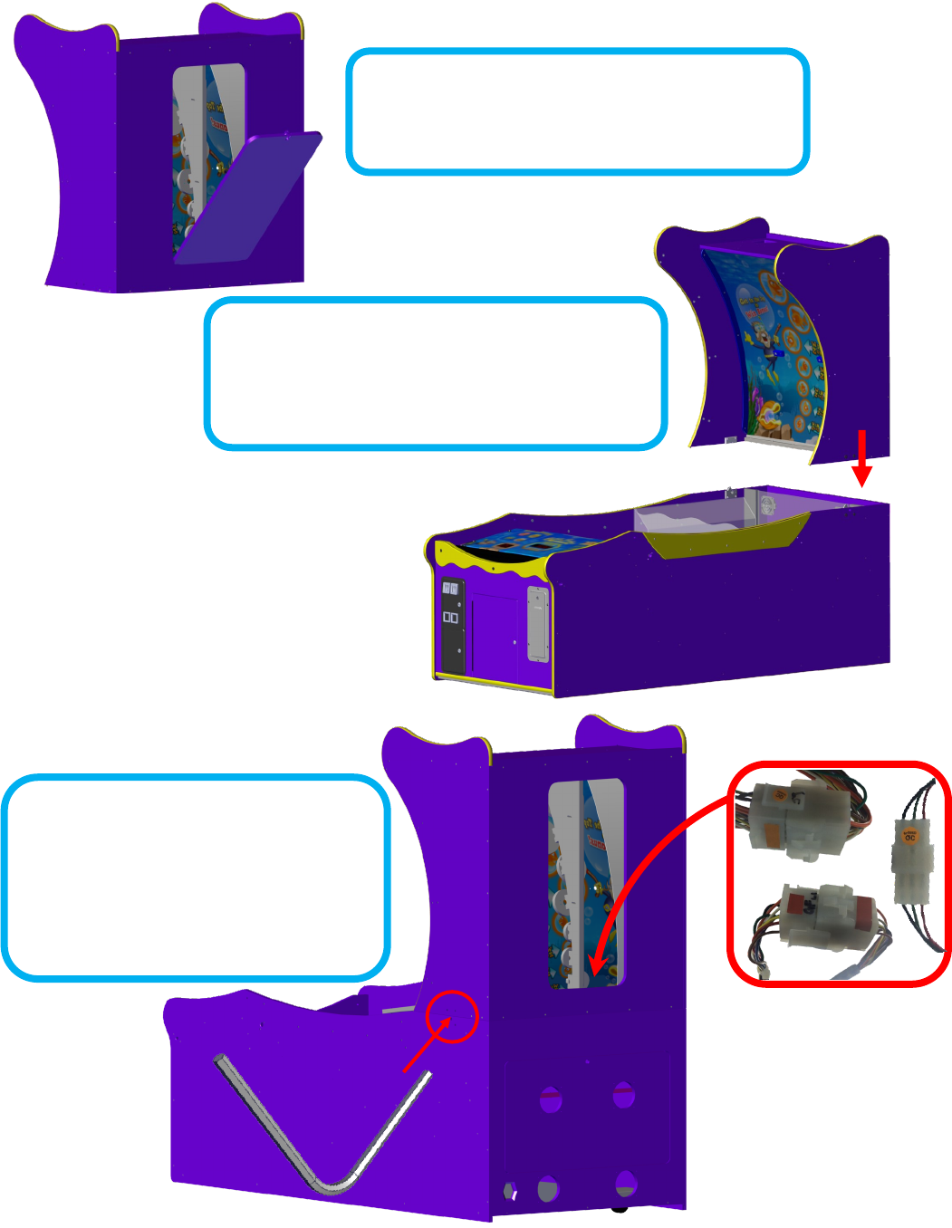
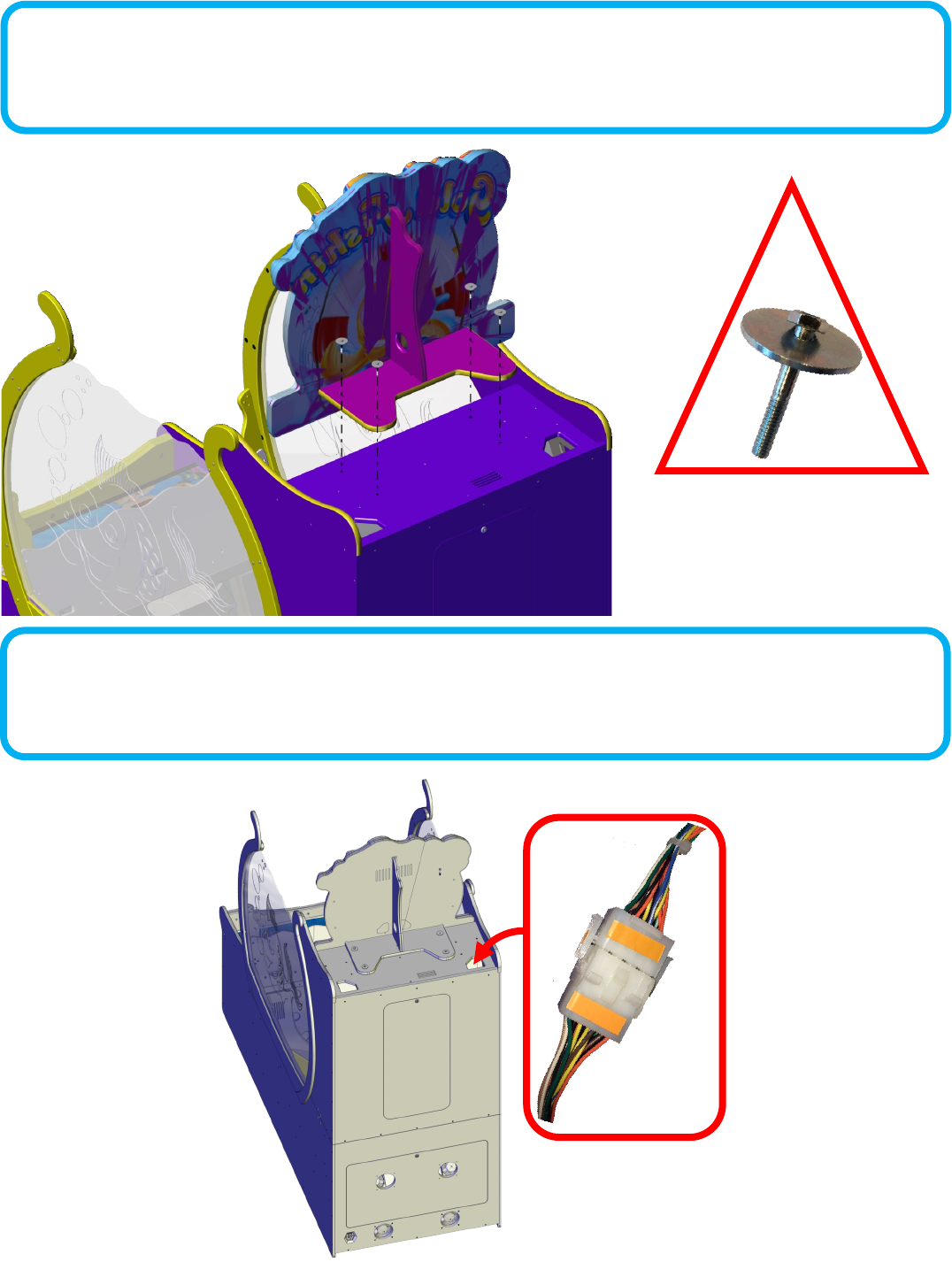
Step 1:
Open the back door of the upper cabinet and put aside.
Step 2:
Carefully li the upper back secon up onto the boom
cabinet.
Step 3:
Lock the upper cabinet to the boom cabinet
using the provided latch tool Connect the
three harnesses shown and replace the back
cabinet door .
Shipped Fully Disassembled Instrucons
6
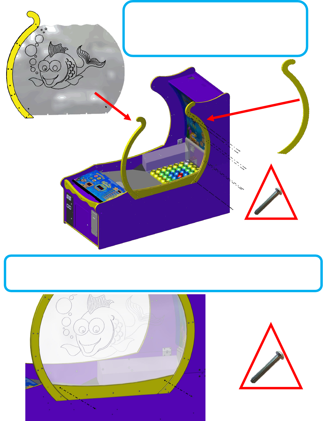
Step 4:
Loosen the boom three bolts that hold the boom bowl support.
Step 5: (DO NOT FULLY TIGHTEN BOLTS)
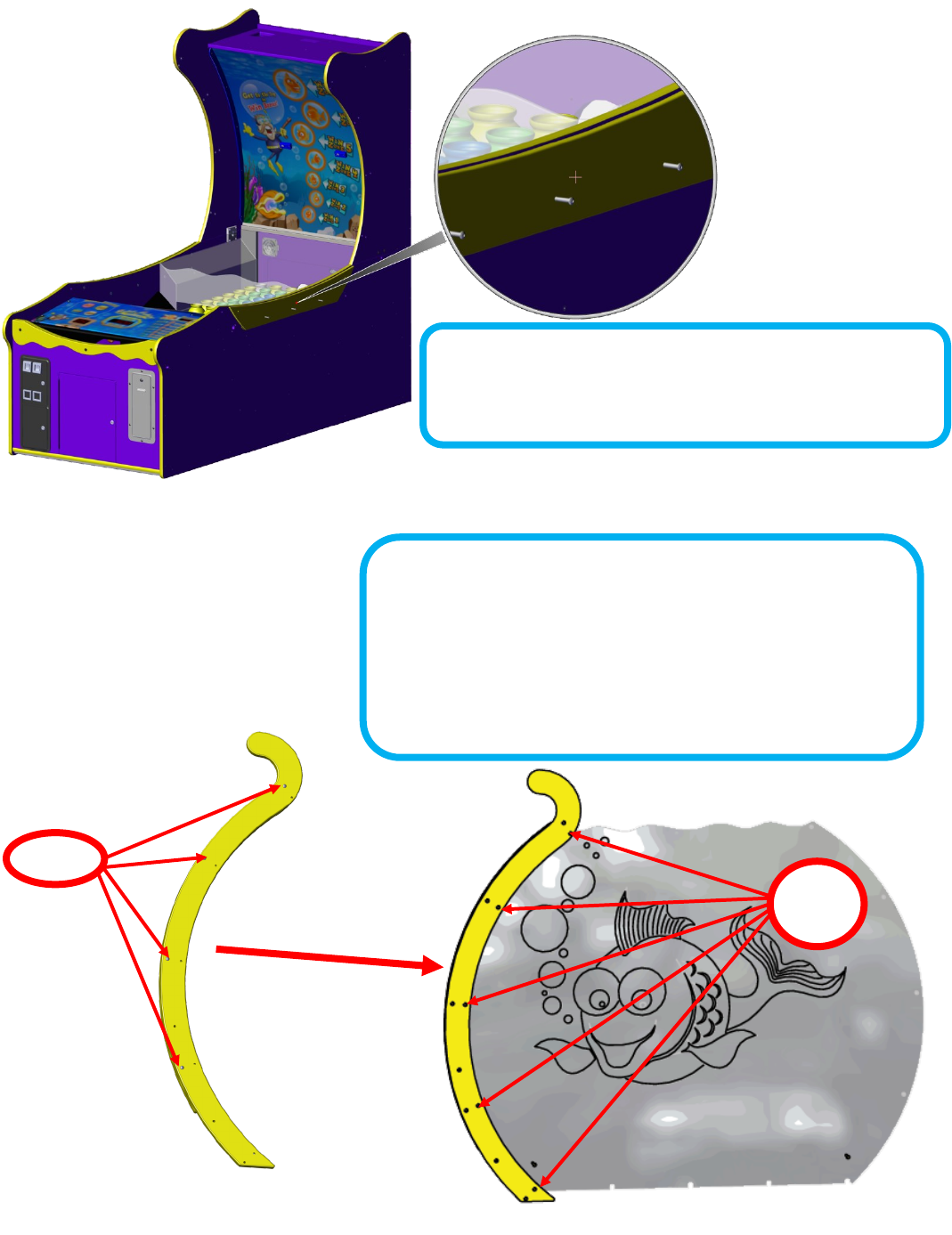
Locate the right bowls’ front bowl support and loosen the outer bolts
so that it can slide onto the shbowl. The shbowl should have its
etching facing to the inside of the game when installed. Using 5 Zinc
1/4-20 x 1 (6048) bolts, aach the le support to the sh bowl. Do
not fully ghten at this me.
6048
bolts
Loosen
7
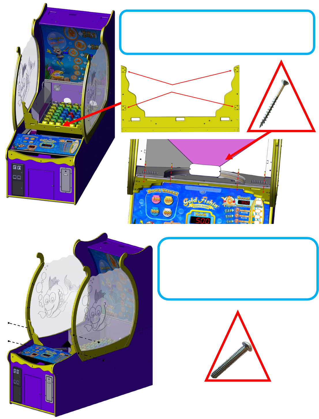
Step 7: (DO NOT FULLY TIGHTEN)
Use 2 AA6102’s Allen bolts to aach the boom of the bowl mount but do not fully ghten.
Step 6: (DO NOT FULLY TIGHTEN BOLTS)
Locate the right bowl and slide it into the boom slot aligning the
notches with the bolts. Aach the side bowl mount using 10 AA6102’s.
Do not fully ghten bolts.
8
Step 8:
Repeat steps 4, 5, 6 and 7 for the le side. The
etching should be on the inside when fully
assembled.
Step 9:
Remove ball ramp and put aside.
9
Brackets go toward the back of the game.
Step 10: (Not all games require this step)
Skip if the ball rebound guard is already aached to the yellow bracket.
Posion the yellow support for the ball rebound guard with the brackets
facing the back of the game. Aach using four AA6719 Phillips screws.
Step 11:
Aach the sides of the guard using four AA6102 silver Allen
bolts, two on each side. The brackets face inside the game
(See step 10 for illustraon). Do not fully ghten unl all four
bolts are installed. Tighten the Phillips screws if installed in
STEP 10. ** Tighten all bolts now. **
10
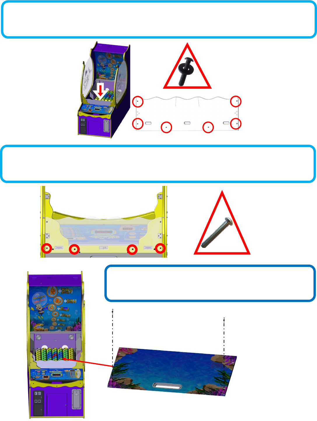
Step 12: (Not all games require this step)
If not already aached to the yellow front supports aach the clear ball bounce shield using 6 black AA6212 washers and 6 black
AA6211 1/4-20 Bolts as shown below.
Step 14:
Replace the ball ramp that was put aside in step 9.
Step 13: (Not all games require this step)
Using AA6211 bolts aach the ball rebound guard assembly to the cabinet where circled.
11
Step 15:
Aach the upper marquee using four silver AA6202 shoulder hex bolts and four AA6070 large silver washers.
Step 16:
Plug the harness shown for the marquee. If not found, open the upper back door and locate the harness.
12
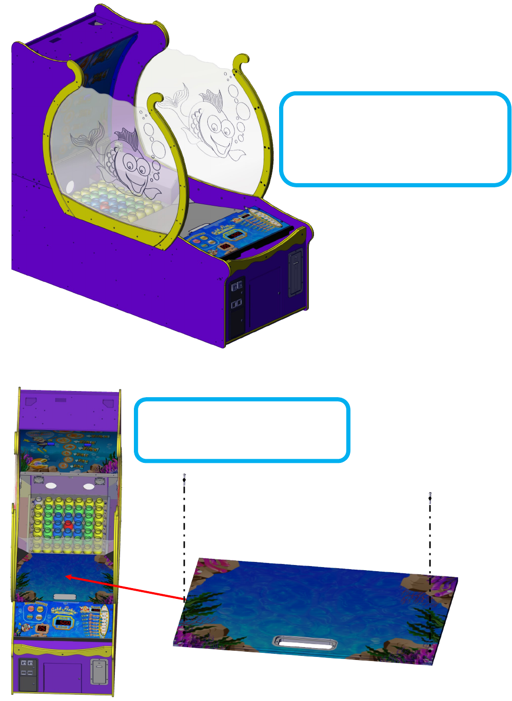
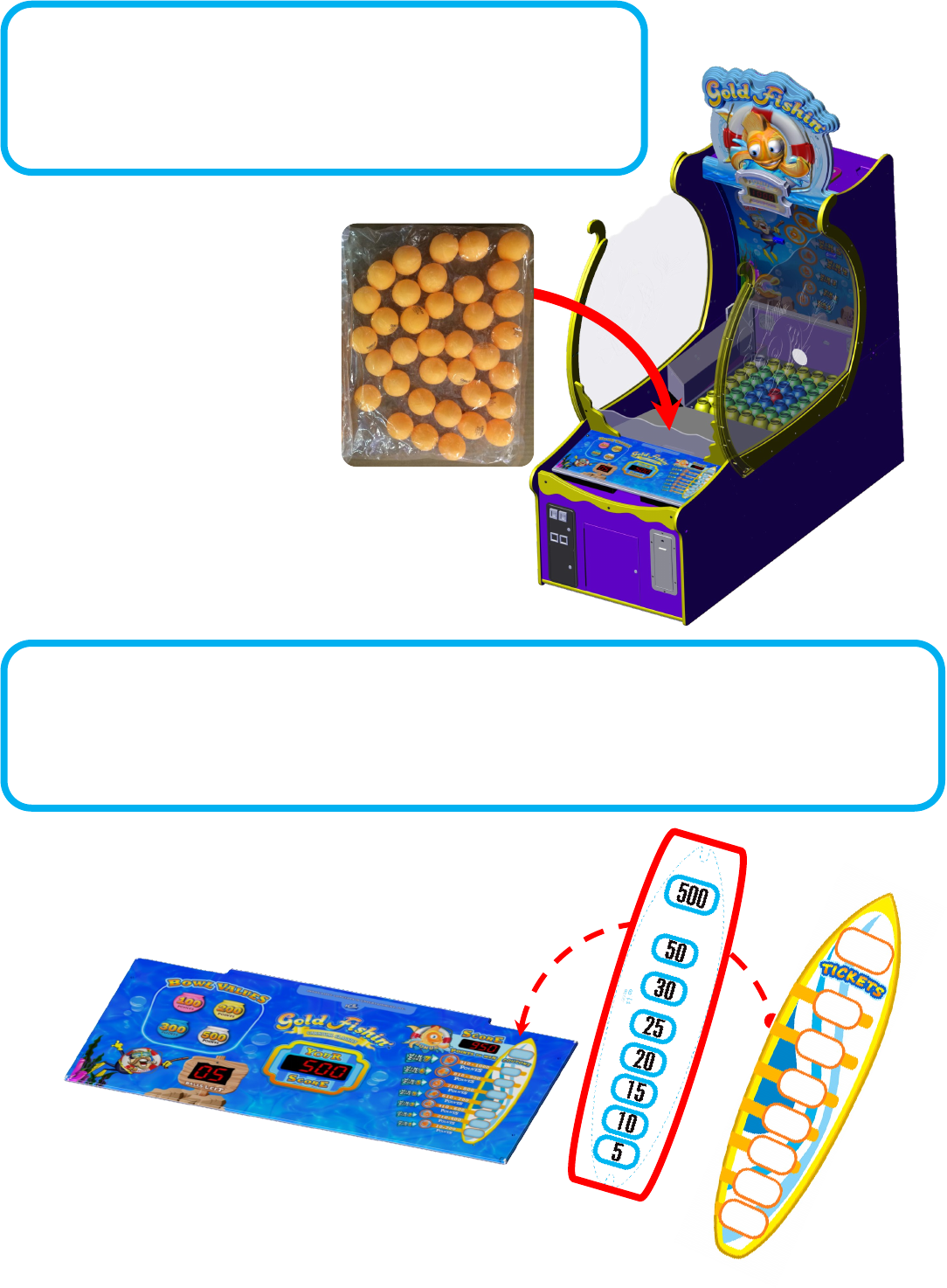
36 BALLS
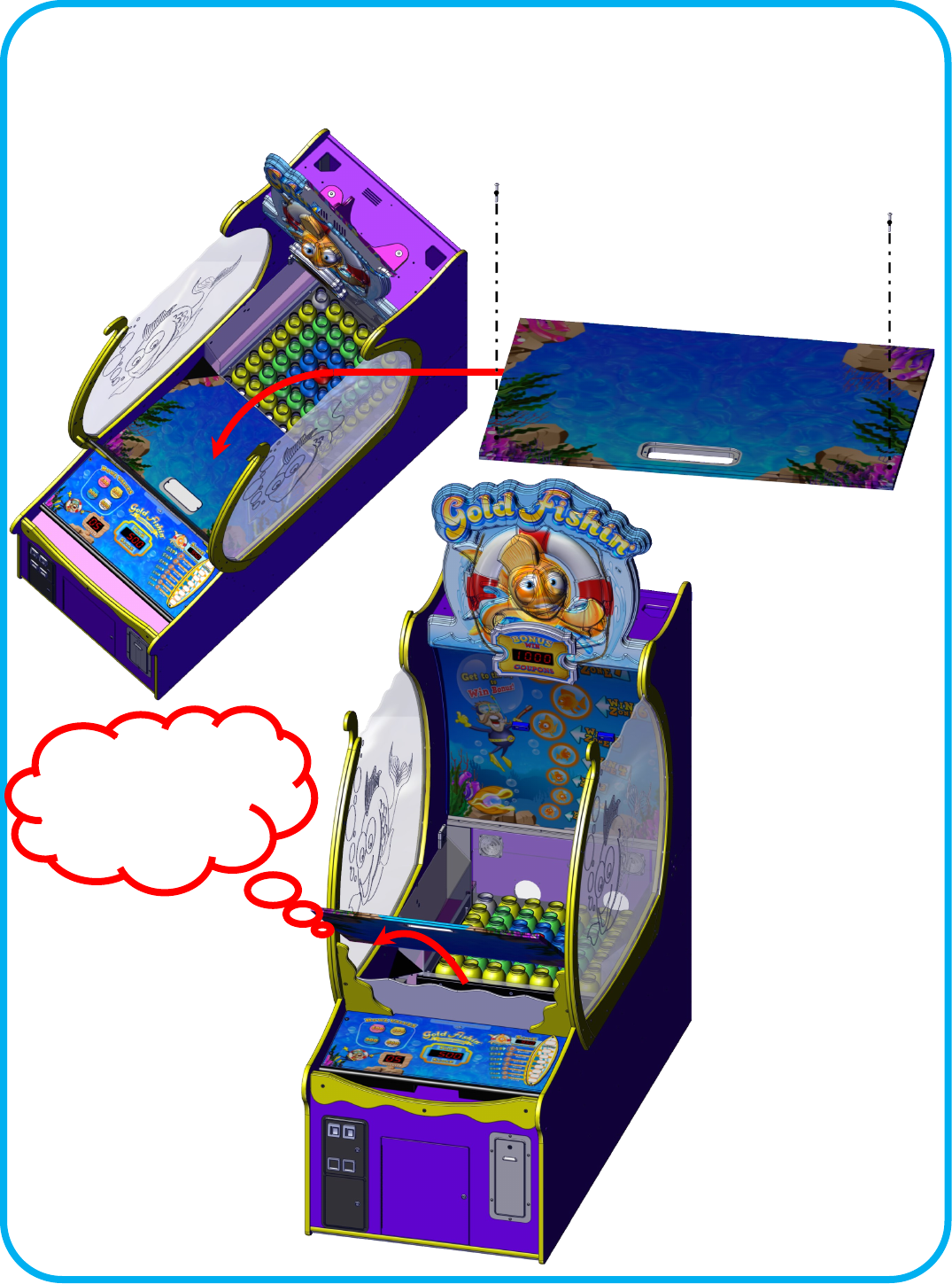
Step 17:
Located in the parts package are two bags of balls. Each bag contains
36 balls. It is recommended to add only one bag to the game. Dump
the bag of balls onto the playeld cover.
Step 18: FINAL STEP
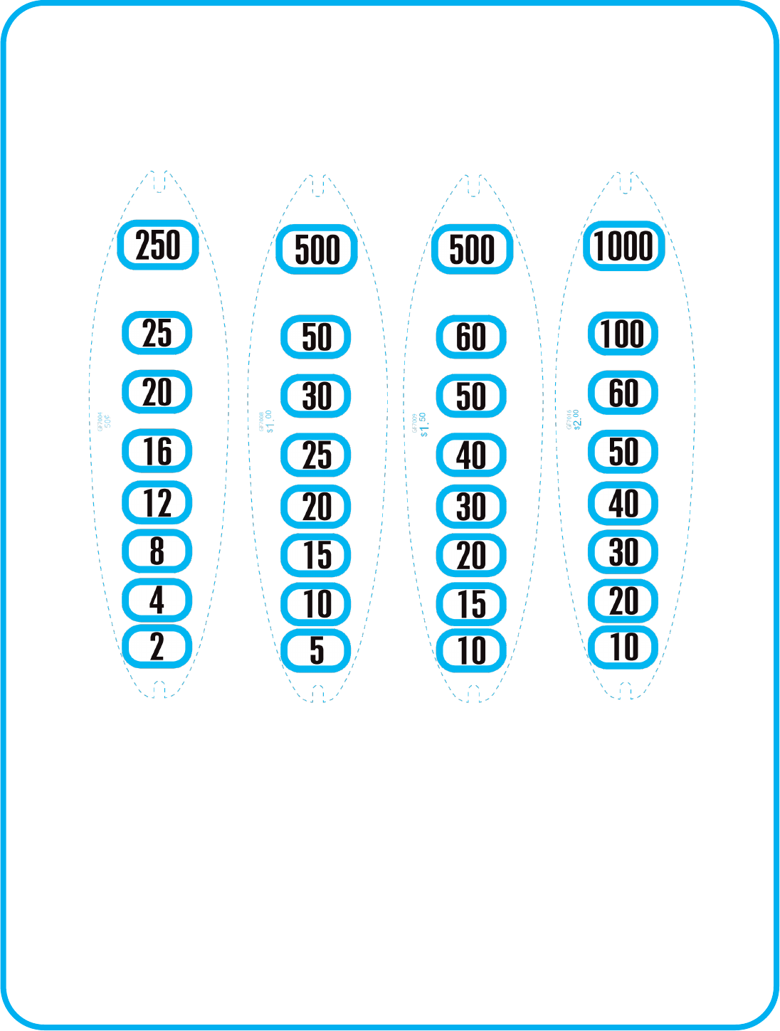
Also located in the parts package are the “Surf board” award cket decals. Choose your desired cket
payout and install under the Surf Board on the control panel. See “Suggested Ticket Awards” for details.
13
GF3235X
Le
QTY 2
Right
QTY 2
GF3232X
GF3228X
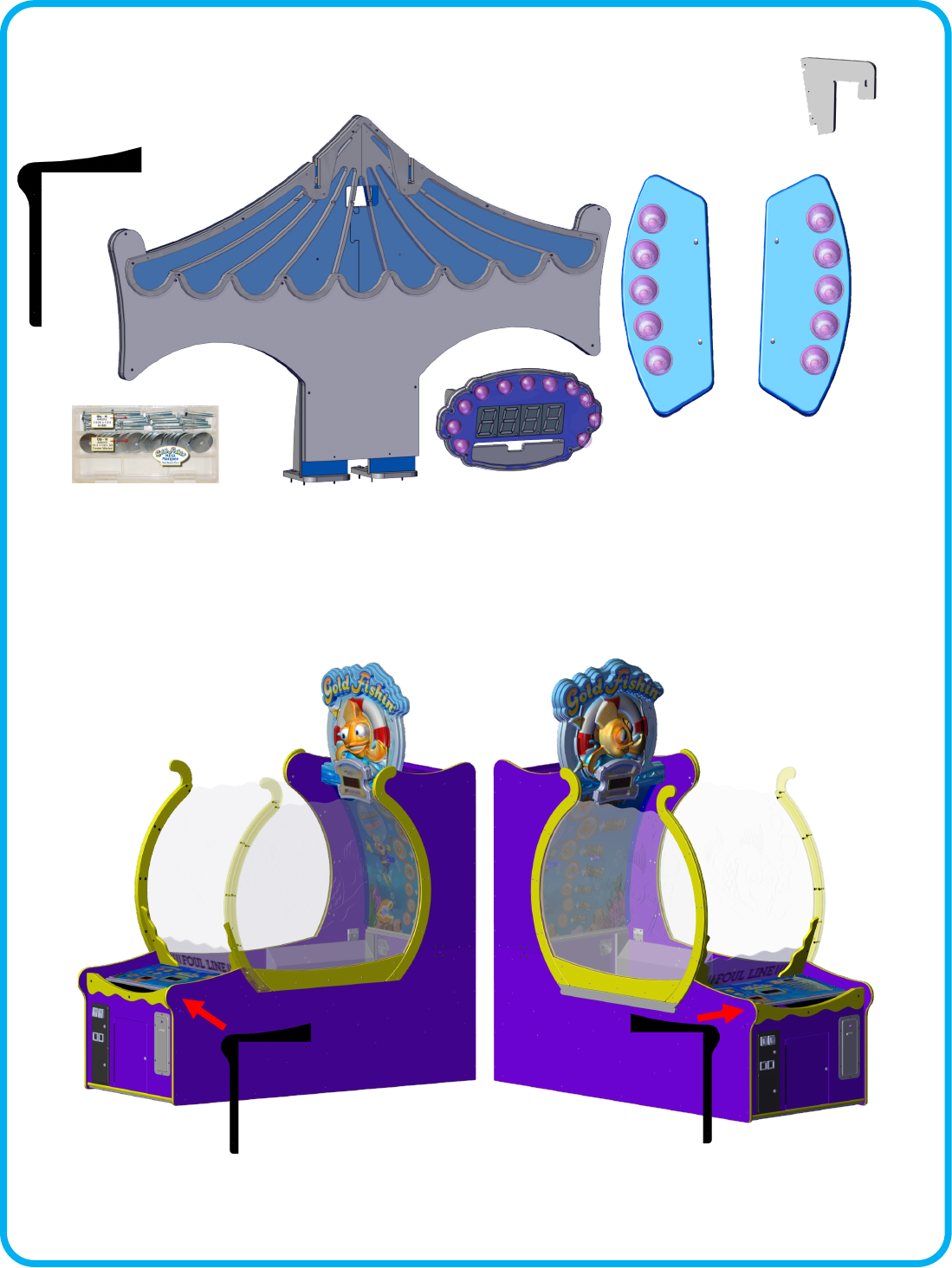
Gold Fishin Mega Marquee Instrucons
Your Mega Marquee should have the follow items included.
Step 1:
Aach the front spacer (GF3250) to each side of the cabinet that will face each other when
pushed together. Use the provided wood screws to mount them to the cabinet. This will take
up the gab between the two games.
GF3250
QTY 2
GF3231
QTY 2
14
Step 3:
Install the bonus lights (GF3232X) onto the upper marquees of two games. There is a le
GF3232X and a right GF3232X. The wire harnesses should all come out the boom of the
GF3232X’s.
Step 2:
Slide the two games together ensuring that the back is square to the front.
15
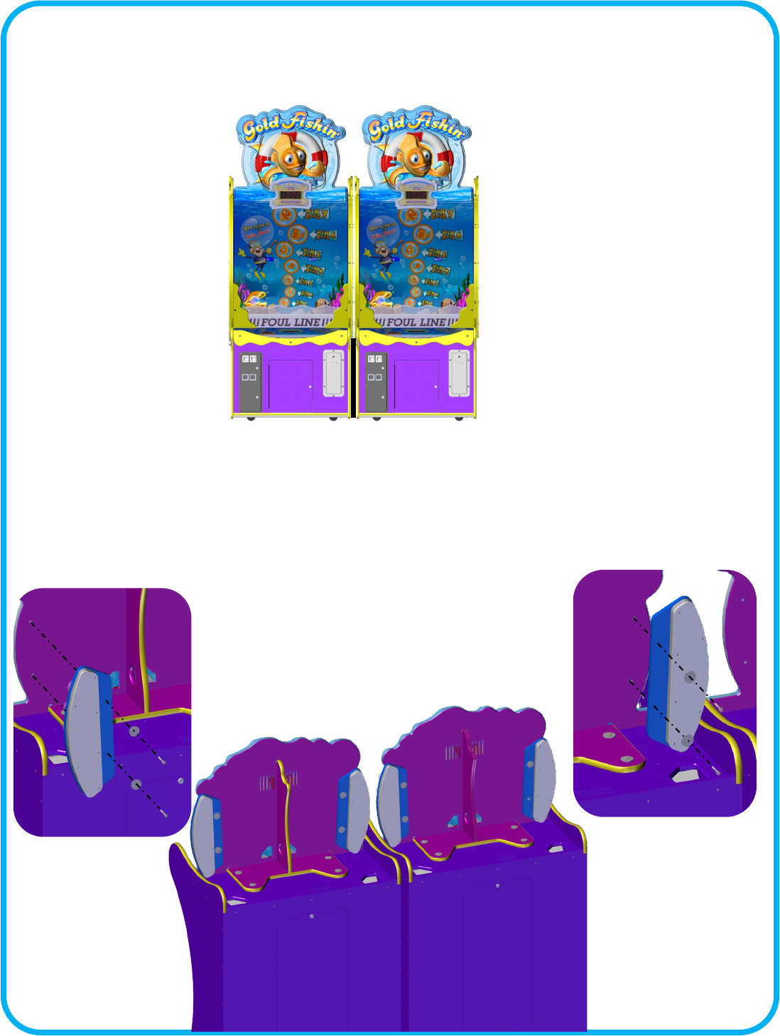
Step 4:
Carefully li the main Mega Marquee (GF3235X) across two games top, behind the upper
marquees. Using eight 6202 bolts and 6070 washers aach the assembly.
Step 5:a (Not all games require this step)
If your brackets are not aached to the sign, remove the four bolts holding the sign together
and put them aside.
16
Step 5b: (Not all games require this step)
Aach the a GF3231 bracket to one side using 3 drywall screws. Repeat for the other side.
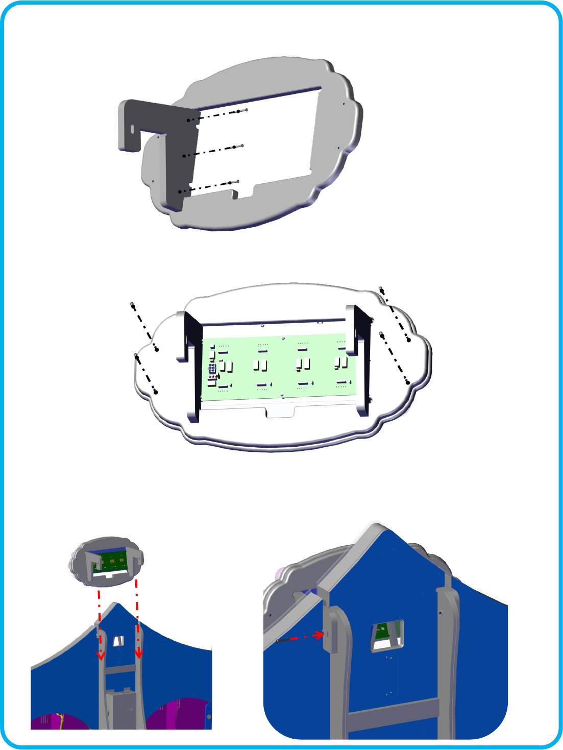
Step d: (All games)
Remove the two mounng bolts located at the top of the Mega Marquee. Slide the GF3228X
display onto the top of the Mega Marquee. Aach the wire three harnesses. Secure with the
two bolts you removed previously.
Step 5c: (Not all games require this step)
Reassemble the sign using the bolts you put aside in step 5a.
17
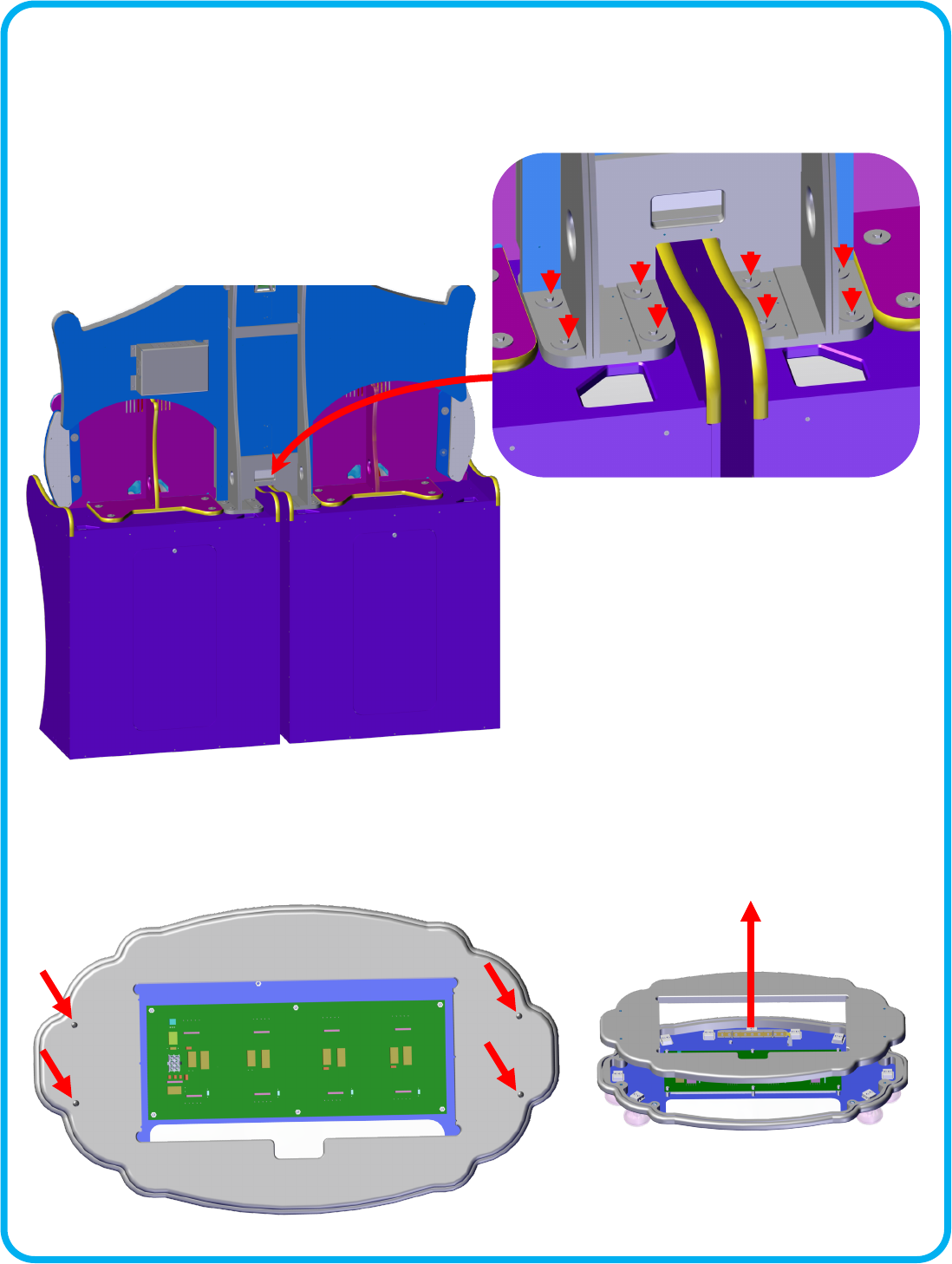
Step 6:
Connect the AC power cord to the Mega Marquee box. Connect the Bonus light harnesses to
each GF3232X Light assemblies. A special communicaon cable should be run from the mega
marquee, down through the boom of one of the cabinets, to the main board’s connector J30.
On some units this cable is already installed in the cabinet. It would be coiled and secured to
the boom of the cabinet. It can be accessed by opening the lower cabinet door.
AC Plug
Communicaon cables
Only 1 is needed
for the marquee.
18
Value
Opon
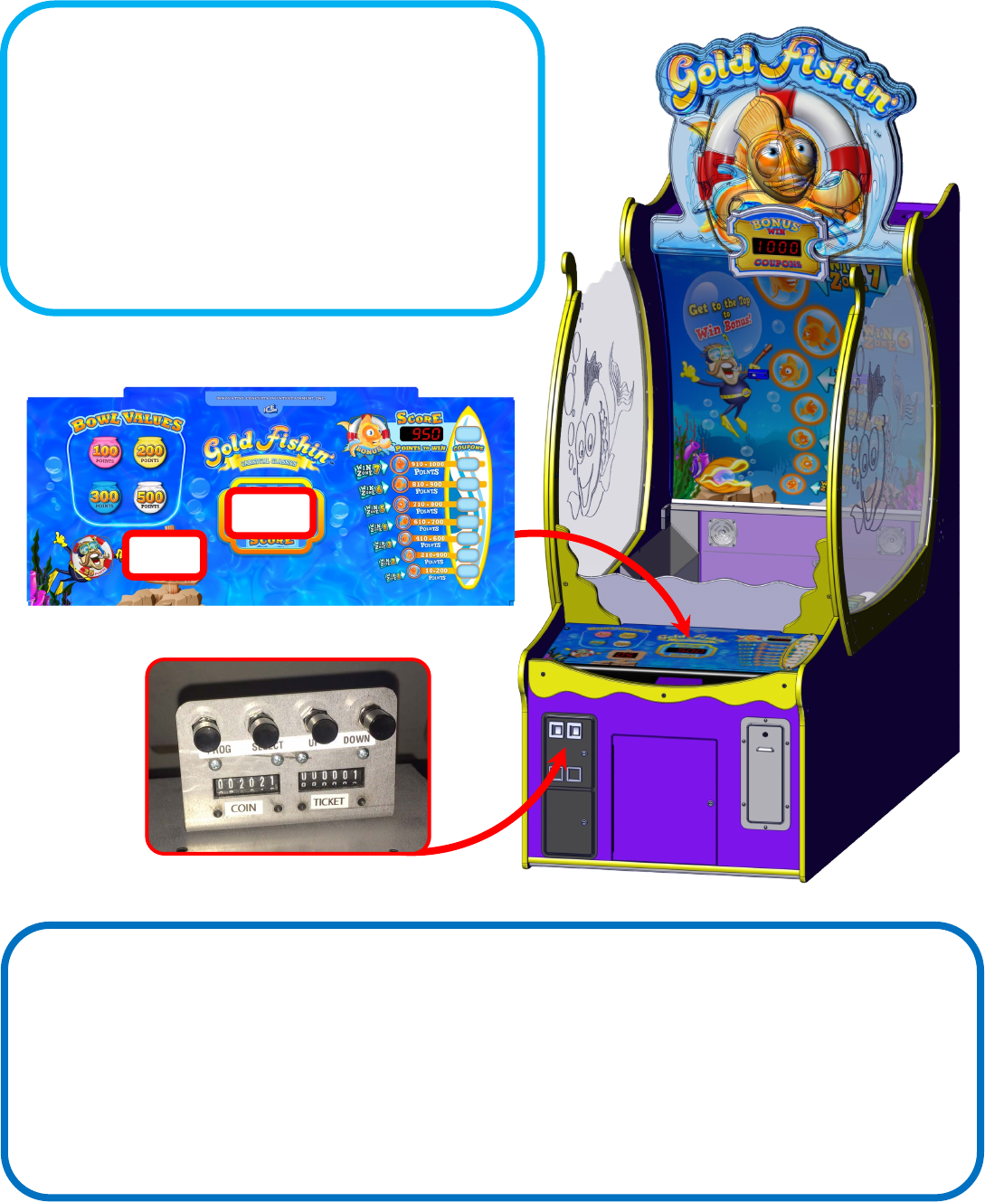
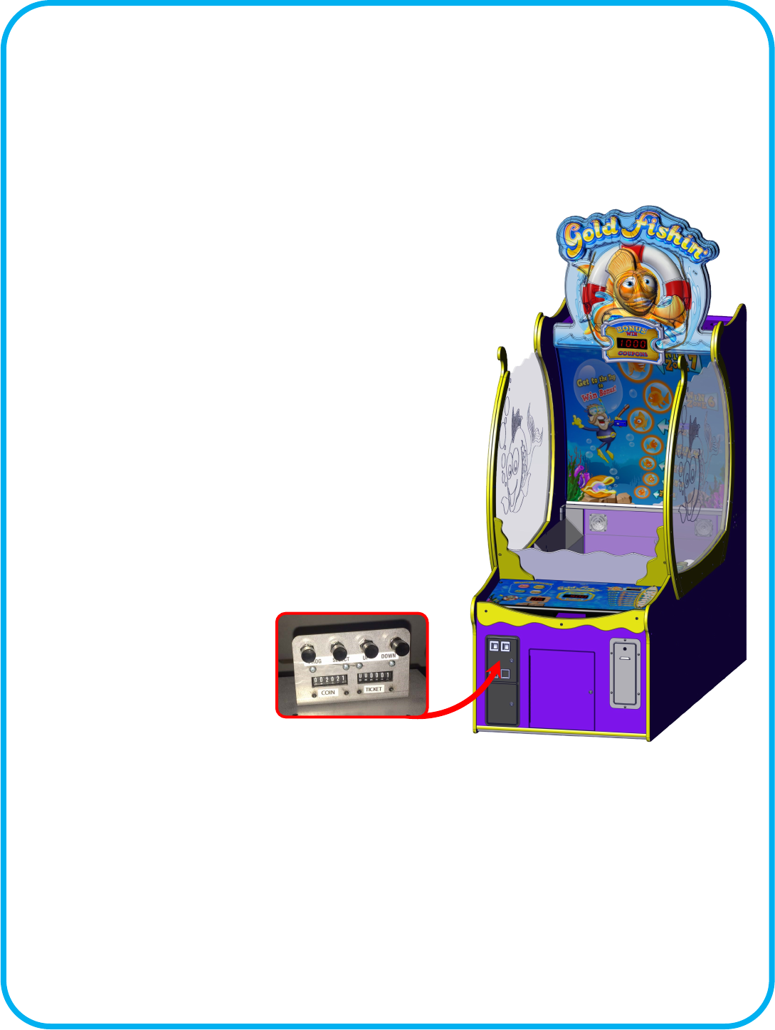
Changing Program Sengs:
To enter program mode you must not be in the middle of a game.
Open the upper coin door and press the “Program” buon. The
control panel will show the opon number in the balls le display.
Your score display shows the value stored for that opon. Press
the “Select” buon to change opons. Press the “UP” and
“DOWN” buons to change the opon’s value.
See “Program Opons” for opon details.
Accounng Mode:
To enter accounng mode you must not be in the middle of a game. Press the “Up” buon located in the upper coin door.
The game will show in the “ball’s le” display the current account number and in the “your score” display show the value. The
game will cycle through all the account numbers and their values stored. To exit account mode without erasing the values
press the “UP” buon again. If you want to clear the accounng values, press the “Down” buon.
See “Account Mode Table” for explanaons of accounts.

19
Programming Opons for Gold Fishin
Opon Min Max Default Inc Descripon
0 0 7 5 1 Game Volume
Adjusts game sound eects.
1 0 7 5 1 Music Volume
Adjust background music
2 0 30 3 1 Aract Time
Adjusts how oen the game will play aract sounds.
3 0 20 1 1 Cost of Game in pulses
How many pulses of coin 1 to start the game?
4 0 20 1 1 Coin 2 Value in Coin 1 increments
How many of coin 1 is coin line 2 worth? Used in seng up dierent
valued coins.
5 10 20 12 1 Number of Balls Per Game
How many balls are given per game.
6 0 2 1 1 Ticket Mulplier sets how the game will pay ckets owed.
A value of 0 will pay 0 ckets for each cket owed.
A value of 1 will pay 1 cket for each cket owed.
A value of 2 will pay 1/2 a cket for each cket owed.
7 0 100 20 1 Ball Timeout denes how long to wait before subtracng a ball
from play.
8 0 100 1 1 Tickets given for a score between 10 - 200
9 0 100 2 1 Tickets given for a score between 210 - 400
10 0 100 3 1 Tickets given for a score between 410 - 600
11 0 100 4 1 Tickets given for a score between 610 -700
12 0 100 5 1 Tickets given for a score between 710 - 800
13 0 100 8 1 Tickets given for a score between 810 - 900
14 0 200 10 1 Tickets given for a score between 910 -1000
15 0 5000 250 25 Tickets given for winning the Bonus
16 0 200 100 1 Add these many points to the score to beat when bonus is won.
17 0 200 5 1 Subtract these many points each me the bonus is not won.
18 0 50 0 1 Seng a value will only pay these many ckets regardless of points.
19 0 1 1 1 Enable or disable the cheat sensor. A value of 1 enables.
20 0 1 0 1 Factory Reset
20
Suggested Ticket Awards
$0.50 Game
GF7004
$1.00 Game
GF7008
$1.50 Game
GF7009
$2.00 Game
GF7016
21
Audit # Descripon
1 Bonus Won
2 Tilts
3 0-99
4 100-199
5 200-299
6 300-399
7 400-499
8 500-599
9 600-699
10 700-799
11 800-899
12 900-999
13 1000-1099
14 1100-1199
15 1200-1299
16 1300-1399
17 1400-1499
18 1500-1599
19 1600-1699
20 1700-1799
21 1800-1899
22 1900-1999
23 2000+
Audit Mode
The game can display various audit informaon about its game play. To display this informaon, open the upper coin door and
press the up buon when not in a game. The “Balls Le” display will show you which audit it is displaying while the “Your Score”
display will show how many mes it was made. The “Tickets to Win” display will show “ACCR” during the audit process. To exit
audits, press the up buon again. If you want to clear the stored audits, press the down buon while the accounng mode is dis-
playing. The “Tickets to Win” display will show “CL”, pause and exit when it has completed erasing all audits.
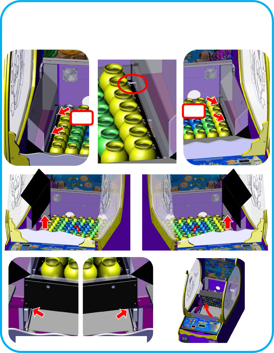
22
Service: Removing the Ball Ramp
Loosen the two Allen bolts shown below. Make sure they are not securing the ball ramp and use them to pry the panel up
and over the front ball deector.
Rest the ball ramp on
yellow frame and use a
pivot point to li the
panel out.
23
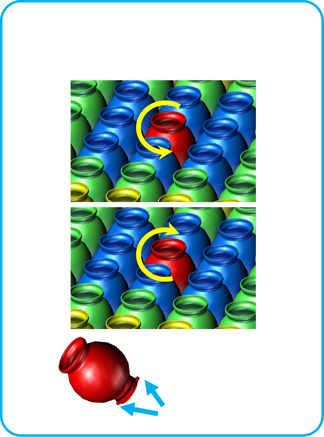
Service: Removing a Fish Bowl
To remove a sh bowl, twist counter clock-wise. The O-ring at the boom of the bowl keeps the bowl
from loosening during game play. Do not add any lubricaon to the O-ring. Doing so can result in
damage to the sensor board below.
To Install, align the notches at the board and twist clock-wise.
REMOVE
INSTALL
Notches
24
Service: Accessing the Sensors:
Remove the ball ramp and put aside. See “Removing the Ball Ramp”. Loosen the four Allen bolts that secure the side ball
deectors. Remove the bowl in front of the bolt if ght. See “Removing a Fish Bowl” for details. Pull the top of the side ball
deectors slightly toward the center of the cabinet and then straight up and out. . Fully li the playeld up.
Loosen
Loosen
SOME UNITS HAVE LOCKING BOLTS OR PINS
25
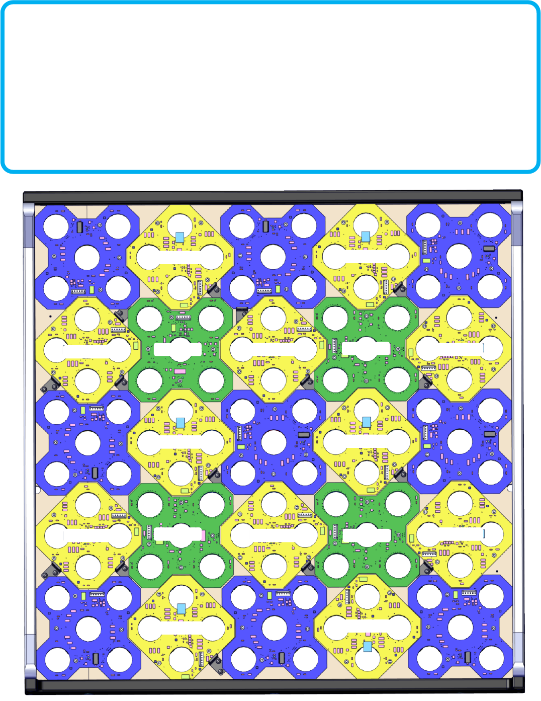
GF2040X GF2040X GF2040X
GF2040X
GF2040X
GF2040X
GF2040X
GF2040X
GF2040X
GF2039X GF2039X
GF2039X GF2039X
GF2039X
GF2039X
GF2039X
GF2039X
GF2039X GF2039X
GF2039X
GF2039X
GF2041X
GF2041X
GF2041X
GF2041X
Sensor Layout
The playeld uses 3 dierent styles of sensors mounted in dierent rotaons depending on where the sensor is mounted.
GF2040X, GF2039X, and GF2041X. The picture below shows the proper order and rotaon of each sensor board. You can use
the same style of sensor at any locaon. When the game is rst powered on, each sensor will numerate itself to the locaon it
is installed. As each sensor numerates, the color of the sh bowl (on top) will change to green. This indicates that the sensor
has assigned itself an ID number for its locaon and then it will transmit this ID number to the game. This is displayed in the
“Balls le” display on the control panel. When the game completes this process it will begin it’s aract mode and await for
coinage to start. If this process doesn’t complete the last reported sensor ID will be displayed on the “Balls le” display.
See “Rotary Diagnosc Modes, mode 7” for trouble shoong informaon.
26
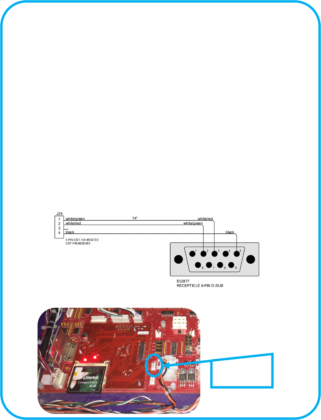
Serial Debug Port
Game Port Diagnosc Connecon:
To use the Port Diagnosc connecon you must connect an addional cable that provides a standard serial port connecon to a PC.
The part number is GF2098LX. The computer must have a serial port and a terminal program installed before using this feature.
You can download free terminal soware from the internet if you do not have a terminal program already installed on your com-
puter. The program “Puy” from www.puy.org can be downloaded for free and is a good terminal program to use. You will also
need to obtain a RS232 serial cable to go between your computer’s serial port and the game’s serial port. If the computer has no
serial ports, the use of a serial to USB device is recommended.
The game’s serial port is located on the main board at J29, right of the CPU sub board. You will need to order ICE part number
GF2098LX serial interface cable in order to aach a standard RS232 serial cable from you. Once the serial cable is connected
launch your terminal program and congure the soware to use a serial connecon. The baud rate is 115200 kbs and uses 8 bits
with no parity bit with 1 stop bit.
Once the connecon is established you will see numbers and leers being displayed as the game is being played. The following list
denes the meaning of those leers and numbers.
When a “B” is displayed this means it is a start of a game. A “D” is displayed when the “Ball Dispense Switch” has been made and a
ball has been dispensed. A “S” followed by numbers in this format “##.#” means “##.” is the score board number and “.#” is the
score sensor number. If a “C” is displayed then the game detected a cheat aempt and lted the game. A “G” means “Give Balls”
and turn on the Ball Dispense Motor. Anyme a “E” is shown means that the ball meout occurred and the ball count le to play is
reduced. A “V” means game
over.
J29 serial connecon
for GF2098LX.
27
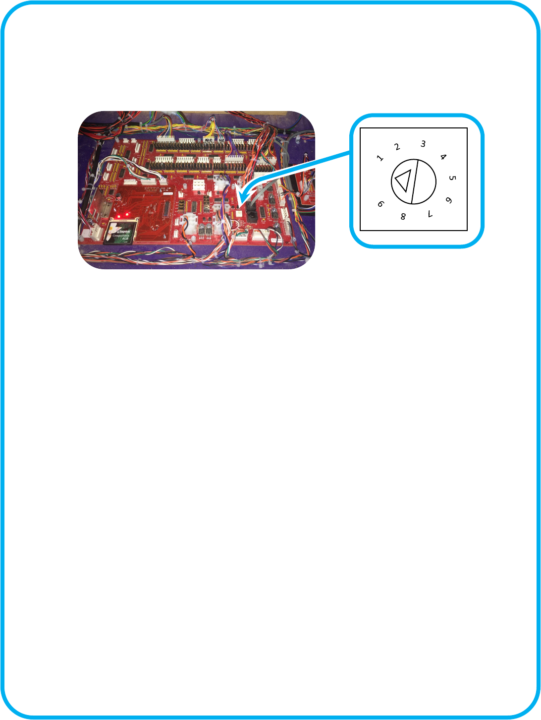
Rotary Diagnosc Modes
Located on the main board is a rotary switch. A small triangle points to numbered posion. This is normally 0 and is the standard
game mode posion. Turning this will run dierent tests. The score display will display a “C” followed by the diagnosc mode
number. The excepon to this is posion 6. To exit out of at any of these modes simply rotate the switch back to the 0 posion.
0
Posion 1 [Color Lock] : This mode will stop the game aer sensor board enumeraon so that you can see the colors that the
sensor board has displayed. This mode can only be enabled during power up sequence.
Posion 2 [Test Holes Dark] : This mode allows you to throw balls onto the playeld. The bowls for each board shall light up
green if that board has sensed a ball. A me out will occur if no other ball has been sensed returning the bowl(s) to dark state
again. If however a second sense for the same hole has occurred before the meout, then RED shall be displayed for that board.
Since there is not a correlaon of holes to lights all the boards bowls will light regardless of which sensor on that board was the
culprit. If physically 2 balls enter the same hole before the meout, than the board will light RED even though that is a valid condi-
on. It is up to the operator to determine if the red is legimate or not. The last RED bowl shall be indicated by the target score
display of xxyy with xx = board ID, yy = sensor number. Valid board ID's are 1-25, and Sensor ID's are 1-5.
Posion 3 [Test Hole Light] : This mode is the same as the mode above, only instead of the bowls being o and turning red or
green, they are white turning red or green as appropriate.
Posion 4 [Test Playeld Lights] : This mode will turn on the bowl lights in and RGB fashion to determine if one or more colors
are not working for a specic bowl. The colors are Red, than both Red and Green, and nally Red, Green, and Blue all together.
The ball display will show which light it is that is currently being changed.
Posion 5 [Cheat Sensor] : This will light the Bonus Tickets light based on the state of the cheat sensor. If the cheat sensor is
clear (not blocked) then the light will be on, if blocked the light will be o.
Posion 6 [Burn in] : This mode is similar to aract with the addion of all the segments displaying 0-9 cycling, and the appropri-
ate game balls will aempt to dispense each cycle of the numbers and Audio will cycle
Posion 7 [Board ID] : This mode will cycle the board ID of 1-25 and send the command to that board to light the LED's. The ball
display will show which ID it is lighng. Should a board have the wrong enumeraon, this should allow that to be idened. -
Board ID is the only mode that will exit enumeraon mode early, this allows you to idenfy which board(s) are not funconing ap-
propriately. Remember that you need to let the enumeraon process stop before selecng this or you will stop the enumeraon
mode early and unknown results may occur.
28
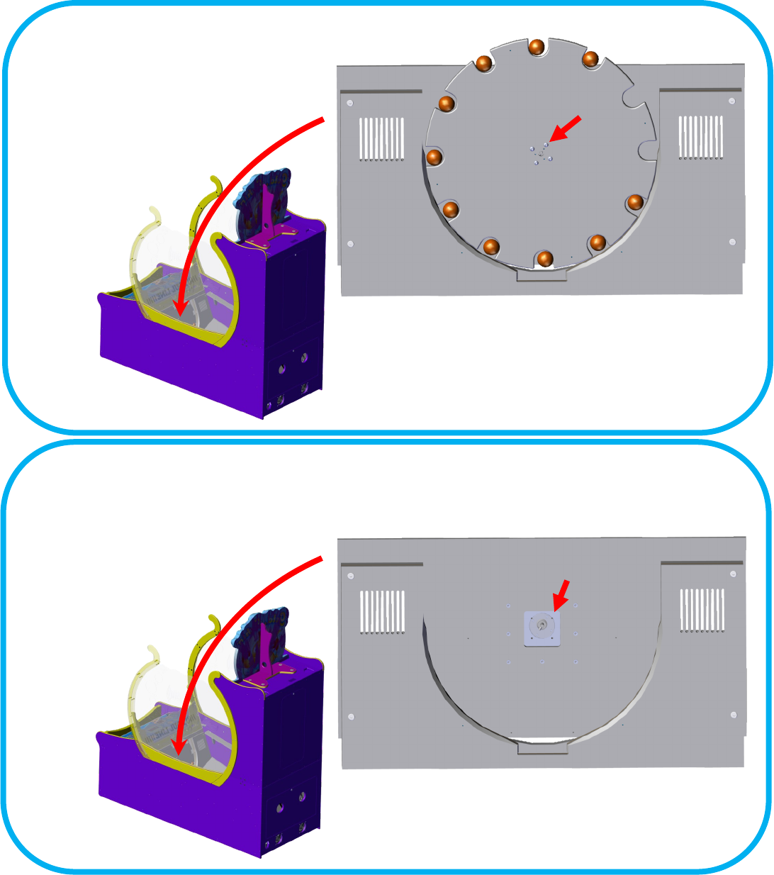
Step 1:
Remove the four screws holding the ball
dispensing wheel.
X’s4
Step 2:
Then remove the four holding the motor
to the motor mount. Unplug harness and
remove through front access door.
X’s4
Ball Dispenser Motor Removal
29
Spare Parts List
Electronics:
PE2034X Main i/o board (no CPU)
E2034XX Brain Board w/ash
MJ2040X Cheat controller
MJ2039RX PCBA Cheat Sensor Receiver
GF2010 +12VDC power supply
WN2010 +5VDC power supply
GF2039X Score Sensor
GF2040X Score Sensor
GF2041X Score Sensor
E00724WNBX ASY (54 RGB LED Tape Strip)
E00788GFAX ASY (White LRG 57 LED Tape Strip)
E007788GFBX ASY (White LRG 12 LED Tape Strip)
E00788GFCX ASY (White LRG 21 LED Tape Strip)
E00788GFDX ASY (White LRG 27 LED Tape Strip)
E00788GFEX ASY (White LRG 30 LED Tape Strip)
E00788GFX ASY (White LRG 63 LED Tape Strip)
E00724CXCX ASY (RGB 12 LED Tape Strip)
E00724GFX ASY (RGB 69 LED Tape Strip)
E020207FL Fan Filter 120MM
E02027BCX ASY (Fan 12 V DC)
E08452 Switch (SPDT) micro
GF1194X ASY (Motor, w/gearbox, plate, etc..)
GF2007X ASY (Power mod 8 AMP)
Hardware:
AA6105 Latch Tool
AA5001A8X ASY Coin Door O/U Black W/Dual
AA5001A-P802X ASY Upper Door Black w/Dual
AA5001A-P802 UPPER Door Blank Black w/Dual
HD1052 Caster (3 swivel)
HH5005 Ticket Dispenser (Entropy)
MA3006 T-molding 25/32 Yellow)
Misc:
CG2027 Power Cord
GF3001X Fishbowl assembly (w insert & Lubed o-ring)
GF3024X Ping Pong Balls (36 per bag)
GF4001X O-ring with lube

30
WARRANTY POLICY
I.C.E. INC warrants all components in new machines to be free of defects in materials and workmanship
for the period listed below:
■ 180 days on Main PCB’s, Computers & Motors
■ 1 year on all LCD monitor panels
■ 90 days on all other electronic and mechanical components
■ 30 days on all I.C.E. repairs and parts purchases
I.C.E. Inc shall not be obligated to furnish a warranty request under the following conditions:
■ Equipment or parts have failed through normal wear and tear
■ Equipment has been subjected to unwarranted stress, abuse or neglect
■ Equipment has been damaged as a result of arbitrary repair/modification
Products will only be covered under warranty by obtaining an I.C.E. authorized RMA #. To obtain an RMA
# please provide I.C.E. tech support with the game serial # or original I.C.E. invoice # and a detailed
description of the failure or fault symptoms.
I.C.E. Inc. will assume no liability whatsoever for costs associated with labor or travel time to replace
defective parts. All defective warranty covered components will be replaced with new or factory
refurbished components equal to OEM specifications.
I.C.E. Inc. will cover domestic UPS ground, or comparable shipping costs during the warranty
period. International or expedited shipments are available for an additional charge. To obtain credit
defective parts must be returned to I.C.E. Inc, at the customer’s expense, within 30 days. After 30 days a
15% re-stocking fee will apply to all returns.
ICE distributors are independent, privately owned and operated. In their judgment, they may sell parts
and/or accessories other than those manufactured by I.C.E. Inc. We cannot be responsible for the quality,
suitability or safety of any non-I.C.E. part or modification (including labor) that is performed by such a
distributor.
