Arcade House Of The Dead 4 Dlx Manual INSERT NUMBER HERE User
2013-11-19
User Manual: Arcade House Of The Dead 4 Dlx Manual
Open the PDF directly: View PDF ![]() .
.
Page Count: 109 [warning: Documents this large are best viewed by clicking the View PDF Link!]
- 1. BEFORE USING THIS PRODUCT
- 2. INSPECT IMEDIATELY AFTER TRANSPORTING
- 3. INTRODUCTION TO THIS SERVICE MANUAL
- 4. INSTALLATION AND SERVICE INSTRUCTIONS
- 5. HOW TO PLAY
- CONTROLLER UNIT (GUN)
- 7. VOLUME CONTROL
- 8. REMOTE CONTROL (DLP)
- 9. MAINTENANCE INSTRUCTIONS
- 10. DESIGN RELATED PARTS
- 11. PARTS LIST
- 11.1. TOP ASSEMBLY (HDF-000-01UK)
- 11.2. ASSY DLP 52 (HDF-0400UK)
- 11.3. ASSY MASK 52 (HDF-0431UK)
- 11.4. ASSY BILLBOARD DX 52” (HDF-0450UK)
- 11.5. ASSY DLP LOWER BASE (HDF-0480UK)
- 11.6. ASSY FAN UNIT UK (HOD-1530UK)
- 11.7. ASSY SU DLP BASE (HDF-0670UK)
- 11.8. ASSY SUB DLP BASE (HDF-0670UK)
- 11.9. ASSY CABINET DX (HDF-1000UK)
- 11.10. ASSY SUB CABINET DX (HDF-1100UK)
- 11.11. ASSY LIGHT COVER R (HDF-1020UK)
- 11.12. ASSY LIGHT COVER L (HDF-1010UK)
- 11.13. ASSY GUN HOLDER L (HDF-1300UK)
- 11.14. ASSY GUN HOLDER R (HDF-1350UK)
- 11.15. ASSY CONTROL PANEL (HDF-2000UK)
- 12. APPENDIX A - ELECTRICAL SCHEMATIC
420-6908-01UK REV 2.00
SERVICE MANUAL
A 52” SHOOTING MINI DELUX GAME
Before using this product, read this SERVICE MANUAL carefully to understand the contents
stated herein. After reading this manual, be sure to keep it available nearby the product or
somewhere convenient in order to be able to refer to it whenever necessary.
Manufactured in the UK by
MANUFACTURING DIVISION (U.K.)

i
CONTENTS
Before using this product, read this SERVICE MANUAL carefully to understand the contents
stated herein. After reading this manual, be sure to keep it available nearby the product or
somewhere convenient in order to be able to refer to it whenever necessary.
1. BEFORE USING THIS PRODUCT........................................................................................................1
2. INSPECT IMEDIATELY AFTER TRANSPORTING ..............................................................................3
3. INTRODUCTION TO THIS SERVICE MANUAL ...................................................................................6
4. INSTALLATION AND SERVICE INSTRUCTIONS................................................................................7
4.1. HANDLING AND INSTALLATION PRECAUTIONS ..........................................................................7
4.2. NAME OF PARTS..............................................................................................................................8
4.3. ACCESSORIES .................................................................................................................................9
4.4. SHIPPING THE GAME BOARD ......................................................................................................10
4.5. ASSEMBLY INSTRUCTIONS..........................................................................................................11
4.5.1. ASSEMBLE THE MACHINE.....................................................................................................12
4.5.2. LEG LEVELLING PROCEDURE ..............................................................................................14
4.5.3. BILLBOARD INSTALLATION PROCEDURE ...........................................................................15
4.5.4. FOR AC WIRING CONNECTION PROCEDURE.....................................................................17
4.5.5. ASSEMBLY CHECK .................................................................................................................18
4.5.6. MOVING THE MACHINE..........................................................................................................25
4.6. FUSES .............................................................................................................................................26
4.7. REPLACEMENT OF FLUORESCENT LAMP AND OTHER LAMPS..............................................27
4.7.1. FLUORESCENT LAMP REPLACEMENT BILLBOARD...........................................................27
4.7.2. FLUORESCENT LAMP REPLACEMENT GUN CABI..............................................................28
4.7.3. START BUTTON LAMP REPLACEMENT ...............................................................................29
4.8. TROUBLESHOOTING .....................................................................................................................29
4.9. GAMEBOARD..................................................................................................................................30
4.9.1. REMOVING THE BOARD ........................................................................................................30
4.10. PERIODIC CHECK AND INSPECTION.......................................................................................31
5. HOW TO PLAY....................................................................................................................................32
5.1. GAME OUTLINE ..............................................................................................................................33
5.2. ITEMS ..............................................................................................................................................36
5.3. PLAY HINTS ....................................................................................................................................37
6. CONTROLLER UNIT (GUN) ...............................................................................................................38
7. VOLUME CONTROL ...........................................................................................................................44
8. REMOTE CONTROL (DLP) ................................................................................................................45
9. MAINTENANCE INSTRUCTIONS.......................................................................................................46
9.1. EXPLANATION OF TEST AND DATA DISPLAY ............................................................................46
9.1.1. VTS ASSEMBLY.......................................................................................................................47
9.1.2. SYSTEM TEST MODE .............................................................................................................48
9.1.3. GAME TEST MODE .................................................................................................................61
9.1.4. ERROR CODES .......................................................................................................................82
9.2. COIN MECH INSTALLATION AND CREDIT BOARD SET UP.......................................................86
9.2.1. INTRODUCTION ......................................................................................................................86
9.2.2. VTS CREDIT BOARD OPTION SETTINGS.............................................................................88
9.2.3. PRICE OF PLAY SETTINGS UK..............................................................................................89
9.2.4. PRICE OF PLAY SETTINGS EURO ........................................................................................90
10. DESIGN RELATED PARTS ................................................................................................................91
10.1. ARTWORK AND GRAPHICS.......................................................................................................91
11. PARTS LIST ........................................................................................................................................92
11.1. TOP ASSEMBLY (HDF-000-01UK) .............................................................................................92
11.2. ASSY DLP 52 (HDF-0400UK) ......................................................................................................93
11.3. ASSY MASK 52 (HDF-0431UK)...................................................................................................95
11.4. ASSY BILLBOARD DX 52” (HDF-0450UK) .................................................................................96
11.5. ASSY DLP LOWER BASE (HDF-0480UK) ..................................................................................97
ii
11.6. ASSY FAN UNIT UK (HOD-1530UK)...........................................................................................98
11.7. ASSY SU DLP BASE (HDF-0670UK) ..........................................................................................99
11.8. ASSY SUB DLP BASE (HDF-0670UK).......................................................................................99
11.9. ASSY CABINET DX (HDF-1000UK) ..........................................................................................100
11.10. ASSY SUB CABINET DX (HDF-1100UK)..................................................................................100
11.11. ASSY LIGHT COVER R (HDF-1020UK)....................................................................................101
11.12. ASSY LIGHT COVER L (HDF-1010UK) ....................................................................................101
11.13. ASSY GUN HOLDER L (HDF-1300UK).....................................................................................102
11.14. ASSY GUN HOLDER R (HDF-1350UK) ....................................................................................102
11.15. ASSY CONTROL PANEL (HDF-2000UK) .................................................................................103
12. APPENDIX A - ELECTRICAL SCHEMATIC .....................................................................................104
12.1. WIRE COLOURS .......................................................................................................................104
12.2. ELECTRICAL SCHEMATIC .......................................................................................................105

1
1. BEFORE USING THIS PRODUCT
To ensure the safe usage of the product, be sure to read the following before using the product. The
following instructions are intended for the use of QUALIFIED SERVICE PERSONNEL ONLY. After carefully
reading and sufficiently understanding the instructions should any activity be carried out on the product.
Only qualified service personnel should carry out maintenance on the product.
Terms such as WARNING! CAUTION, and IMPORTANT! Are used where an explanation is given which
requires special attention, depending on the potential risk. SEGA is not responsible for injury or damage
caused by use in a manner contrary to the instructions stated in this document. In order to prevent
accidents warning stickers and printed instructions are applied in the places where a potentially hazardous
situation relating to the product could arise. Be sure to comply with these warnings.
Indicates that mishandling the product by
disregarding this warning will cause a potentially
hazardous situation, which can result in death or
serious injury.
Indicates that mishandling the product by
disregarding this caution will cause a potentially
hazardous situation, which can result in
personal injury and or material damage.
This is cautionary information that should be complied with when handling the product. Indicates that
mishandling the product by disregarding this will cause a potentially hazardous situation that may not result
in personal injury but could damage the product.
o Be sure to turn off the power and disconnect from the mains supply before working on the machine.
o Ensure that the correct fuse(s) is fitted to the machine.
o Details of the correct fusing of the machine are enclosed in the Service Manual.
o Ensure that only qualified Service Engineers perform any maintenance work on the machine.
o Specification changes, removal of equipment, conversion and/or addition, not designated by SEGA
are not permitted and will invalidate this product’s CE conformity.
o The parts of the product also include any warning labels or safety covers for personal protection
etc. A potential hazard will be created if the machine is operated while any parts have been
removed. Should any doors, lids or protective covers be damaged or lost, do not operate the
product. SEGA is not liable in any whatsoever for any injury and/or damage caused by specification
changes not designated by SEGA.
o Before installing the product, check for the Electrical Specification Sticker, SEGA products have a
sticker on which the electrical specifications are detailed. Ensure that the product is compatible with
the power supply voltage and frequency requirements of the location in which the machine is to be
installed.
o When installing this equipment ensure the socket outlet is near the machine and is easily
accessible.
o Install and operate the machine only in places where appropriate lighting is available, allowing
warning stickers to be clearly read.
o To ensure maximum safety for customers and operators, stickers and printed instructions
describing potentially hazardous situations are applied to places where accidents could occur.
Ensure that where the product is operated has sufficient lighting to allow any warnings to be read. If
any sticker or printed warning is removed or defaced, do not operate the machine, until it has been
replaced by an identical item.
o When handling the monitor, be very careful. (Applies only to product with monitor)
2
o Some of the monitor (TV) parts are subject to high-tension voltage. Even after turning off the power
some components are still occasionally subject to high-tension voltage. Qualified service engineers
should perform monitor repair and replacement only.
o In cases where commercially available monitors and printers are used only the contents relating to
this product are stated in this manual. Some commercially available equipment has functions and
reactions not stated in this manual. Read this manual in conjunction with the specific manual of
such equipment.
o Descriptions contained herein may be subject to change without prior notification.
o The contents described herein are fully prepared with due care. However, should any question
arise or errors be found please contact SEGA.

3
2. INSPECT IMEDIATELY AFTER TRANSPORTING
• Inspection should only be carried out by QUALIFIED SERVICE PERSONNEL.
Normally, at the time of shipment, SEGA products are in a state to allowing usage immediately after
transporting to the location. Nevertheless, an irregular situation may arise during transportation preventing
this. Before turning on the power, check the following points to ensure that the product has been
transported safely.
• Are then any dented parts or defects (cuts, etc.) on the external surfaces of the product?
• Are castors and leg adjusters present and undamaged?
• Do the power supply voltage and frequency requirements meet with the local supply?
• Are all wiring connectors correctly and securely connected? Unless connected in the correct direction,
connector connections cannot be made successfully. Do not insert connectors forcibly.
• Are all IC’s of each IC BD firmly inserted?
• Does the power cord have any cuts or dents?
• Do fuses meet the specified rating?
• Are such units such as monitors, control equipment, IC BD, etc. firmly secured?
• Are all earth wires connected?
• Are all accessories available?
• Can all doors and lids be opened with the accessory keys and/or tools?
4
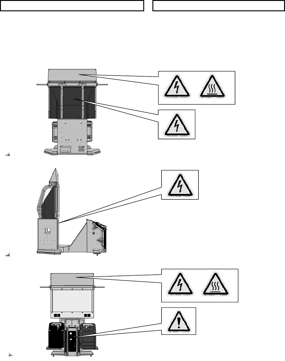
CONCERNING THE STICKER DISPLAY CONCERNING WARNING STICKERS
SEGA product has stickers describing the product
manufacture number (Serial Number) and
electrical specification. If you require service
assistance you will require the Serial Number.
Identical machines may have different parts fitted
internally. Only by quoting the Serial Number will
the correct parts be identified.
SEGA product has warning displays on
stickers, labels or printed instructions
adhered/attached to or incorporated in the
places where hazardous situations can arise.
The warning displays are intended for the
accident prevention of customers and service
personnel.
5
SPECIFICATIONS
Installation Space (cm): L300 X W240 (approx)
Height (cm): 250 (approx)
Weight (kg): 180kg (approx)
Power, Max: Rated Voltage (V.AC):
Rated Current (A):
230vac
3A
Note: Descriptions in this manual are subject to change without prior notice.
6
3. INTRODUCTION TO THIS SERVICE MANUAL
SEGA ENTERPRISES LTD. supported by its experience in electronic high technology of VLSI’s,
microprocessors etc. and with a wealth of experience, has for more than 30 years been supplying various
innovative and popular games to the world market. This Service Manual is intended to provide detailed
descriptions together with all the necessary information covering the general operation of electronic
assemblies, electro mechanicals, servicing controls, spare parts, etc. as regards House of the Dead 4
Deluxe, a new SEGA product. This manual is intended for those who have knowledge of electricity and
technical expertise especially in IC’s, CRT’s, microprocessors etc. Carefully read this manual to acquire
sufficient knowledge before working on the machine. Should there be any malfunction, non-technical
personnel should under no circumstances touch the interior systems. Should such a situation arise contact
the nearest branch listed below or our head office.
SEGA AMUSEMENTS EUROPE LTD.
Suite 3a.
Oak House
12-22 West street
Epsom
Surrey
United Kingdom
KT18 7RG
Telephone: +44(0) 1372 731820
Fax: +44(0) 1372 731849
7
4. INSTALLATION AND SERVICE INSTRUCTIONS
• Installation and commissioning should only be carried out by QUALIFIED
SERVICE PERSONNEL.
4.1. HANDLING AND INSTALLATION PRECAUTIONS
When installing or inspecting the machine, be very careful of the following points and pay attention to
ensure that the player can enjoy the game safely.
The game must NOT be installed under the following conditions:
• Outside, the game is designed for indoor use only.
• In areas directly exposed to sunlight, high humidity, dust, excessive heat or extreme cold.
• In locations that would present an obstacle in the case of an emergency i.e. near fire equipment or
emergency exits.
• On unstable surfaces or surfaces subject to vibration.
• Where liquids, other than routine cleaning, may come into contact with the game.
Important:
• This machine should only be installed by Qualified Service Personnel.
• Be sure to switch the supply power OFF and remove the mains supply plug from the machine before
any work is carried out on the machine.
• Do not attempt to repair the PCB’s (Printed Circuit Boards) yourself. This will void the warranty. The
PCB’s contain static sensitive devices that could be damaged.
• Always return a faulty part to your distributor with adequate packaging and protection.
• When removing the plug from the mains always grasp the plug not the cable.
• Do not use a fuse that does not meet the specified rating.
• Make sure all connections are secure before applying power.
• Ensure that the mains lead is not damaged. If the mains lead is damaged in any
way there could be a danger of electric shock or a fire hazard.
• Ensure that the power supply is fitted with circuit protection. Using the power
supply without circuit protection is a fire hazard.
8
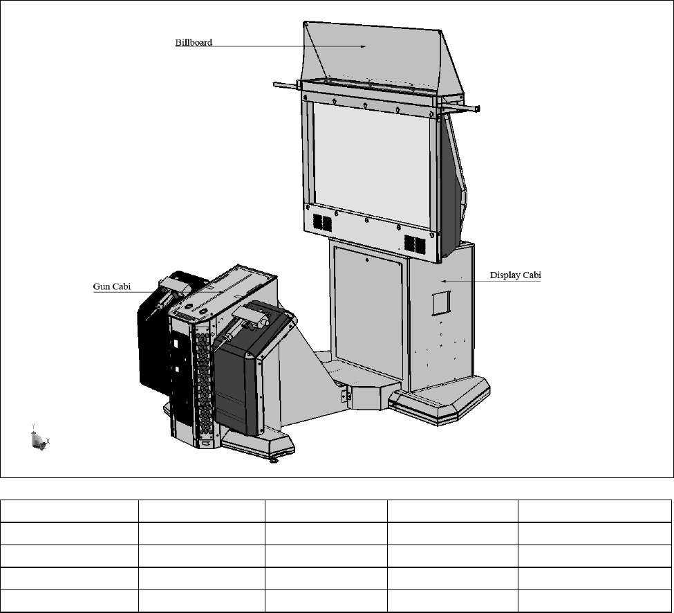
4.2. NAME OF PARTS
Width (cm) Length (cm) Height (cm) Weight (kg)
DISPLAY CABI 150 68 194 90kg approx
GUN CABI 120 130 96 90kg approx
POP PANEL 128 21 36 .5kg
When Assembled 190 192 225 180kg approx
9
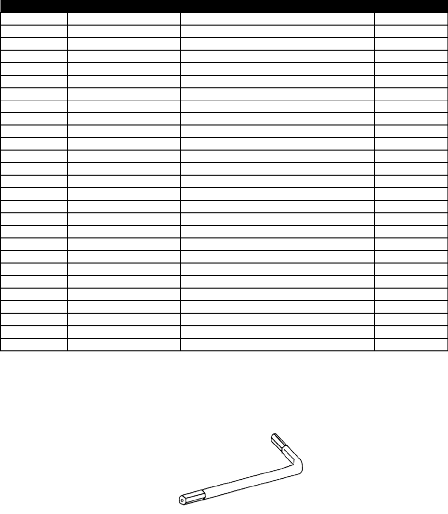
4.3. ACCESSORIES
The machine is supplied with an installation kit. Please ensure the following parts are supplied:
SEQ PT NUMBER DESCRIPTION QTY
**1 440-CS0186UK STICKER C EPILEPSY MULTI 1
**2 SAECE-135 DECLARATION OF CONFORMITY 1
**3 HDF-2003UK DECAL INST PLATE HDF SDX MULTI 1
**4 540-0043-91 L-WRENCH FOR HEX SOC 3MM 1
**5 540-0006-01 WRENCH M4 TMP PRF 1
**6 540-0007-01 WRENCH M5 TMP PRF 1
**7 HDF-0405UK ASSY BANNER R 1
**8 HDF-0406UK ASSY BANNER L 1
**9 610-0727-003 DVD SOFT KIT HDF 1
**301 LM1246 EUROLEAD 10A EUROPEAN SOCKET 1
**302 LM1227 UK MAINS LEAD 10A WITH PLUG 1
**401 OS1019 SELF SEAL BAG 9X12.3/4 2
**402 420-6908-01UK SERVICE MANUAL HDF SDX 52 1
**403 XXX-XXXX-LG LG DISPLAY MANUAL + REMOTE CONT
R
1
**404 350-5801 MOTOR DC5V TG-01H 2
**405 509-5080 SW MICRO TYPE (SS-5GL2) 2
**406 514-5078-2000 FUSE 2A CER 20MM RS419-779 3
**407 514-5079-10000 FUSE 10A T CER 32MM RS414-061 1
**408 514-5078-10000 FUSE 5X20 CERAMIC SB 10000MA 1
**409 514-5090-3000 3A FUSE 6.3MMX25MM CERAMIC T 1
***2 HDF-0452UK BRKT LIGHT BILLBOARD PLATE 1
***3 HDF -0453UK BILLBOARD PLATE (fixed to ITEM 2) 1
***4 HDF-0454UK SUPPORT LEFT 1
***5 HDF-0455UK SUPPORT RIGHT 1
***8 HDF-0454BUK ARTWORK SIDE L (fixed to ITEM 4) 1
***9 HDF-0455BUK ARTWORK SIDE R (fixed to ITEM 5) 1
***202 030-000620-SB M6X20 BLT W/S BLK 12
Item 5 AND 6 - Tamper-proof TORX wrenches.
10
4.4. SHIPPING THE GAME BOARD
• When returning the GAME BOARD for repair or replacement, be sure to package
the entire ASSY SHIELD CASE in the original card transit box - THERE ARE NO
USER-SERVICEABLE PARTS INSIDE.
• Failure to return the GAME BOARD in this manner may invalidate the warranty.
Wrap the ASSY GAME BOARD with the packaging material and put it in the original transit box as shown.
Putting it upside down or packing otherwise in the manner not shown can damage the GAME BOARD and
parts.
11
4.5. ASSEMBLY INSTRUCTIONS
• Perform the assembly by following the procedure herein stated. Failure to comply
with the instructions, for example, inserting the plug into an outlet at a stage not
mentioned in this manual can cause an electric shock
• Assembling should be performed as per this manual. Since this is a complex
machine, erroneous assembling can cause damage to the machine, or
malfunction to occur.
• Do not attempt to complete this work alone, a minimum of 2 people are required.
• Assembly should only be carried out by QUALIFIED SERVICE PERSONNEL.
When carrying out the assembly work, follow the procedure in the following sequence.
STEP 1 ASSEMBLE THE MACHINE
STEP 2 LEG LEVELLING PROCEDURE
STEP 3 BILLBOARD INSTALLATION PROCEDURE
STEP 4 FOR AC WIRING AND CONNECTION PROCEDURE
Note that the parts contained within the installation kit are required for the assembly work.
• Fit all fixings loosely first as detailed in step 1, then position all components
before finally tightening fixings at step 4.
12
4.5.1. ASSEMBLE THE MACHINE
• This operation should only be carried out by QUALIFIED SERVICE
PERSONNEL.
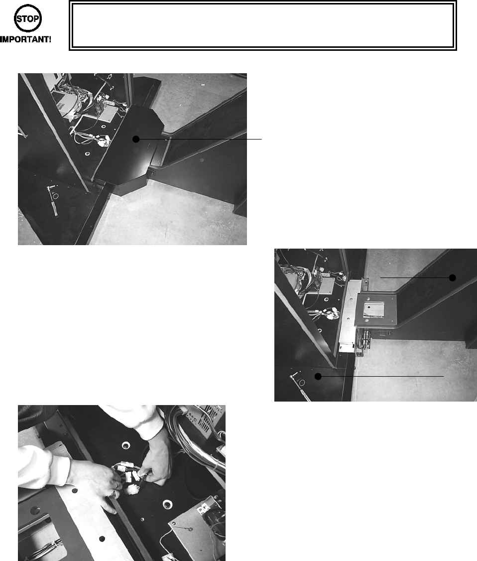
STEP 1
• Remove the JOINT COVER (HDF-
1031UK) from over the joint of the 2
cabinets (2x M5x16 PAN PAS BLK and
2x M6x50 HEX BOLT BLK.)
• Join both DLP and GUN cabinets as pictured
(left).
• Feed the harnesses from the Gun cabinet
up through the access hole in the DLP
cabinet.
• Make all 5 harnesses connection good.
Gun Cabinet
DLP Cabinet
13
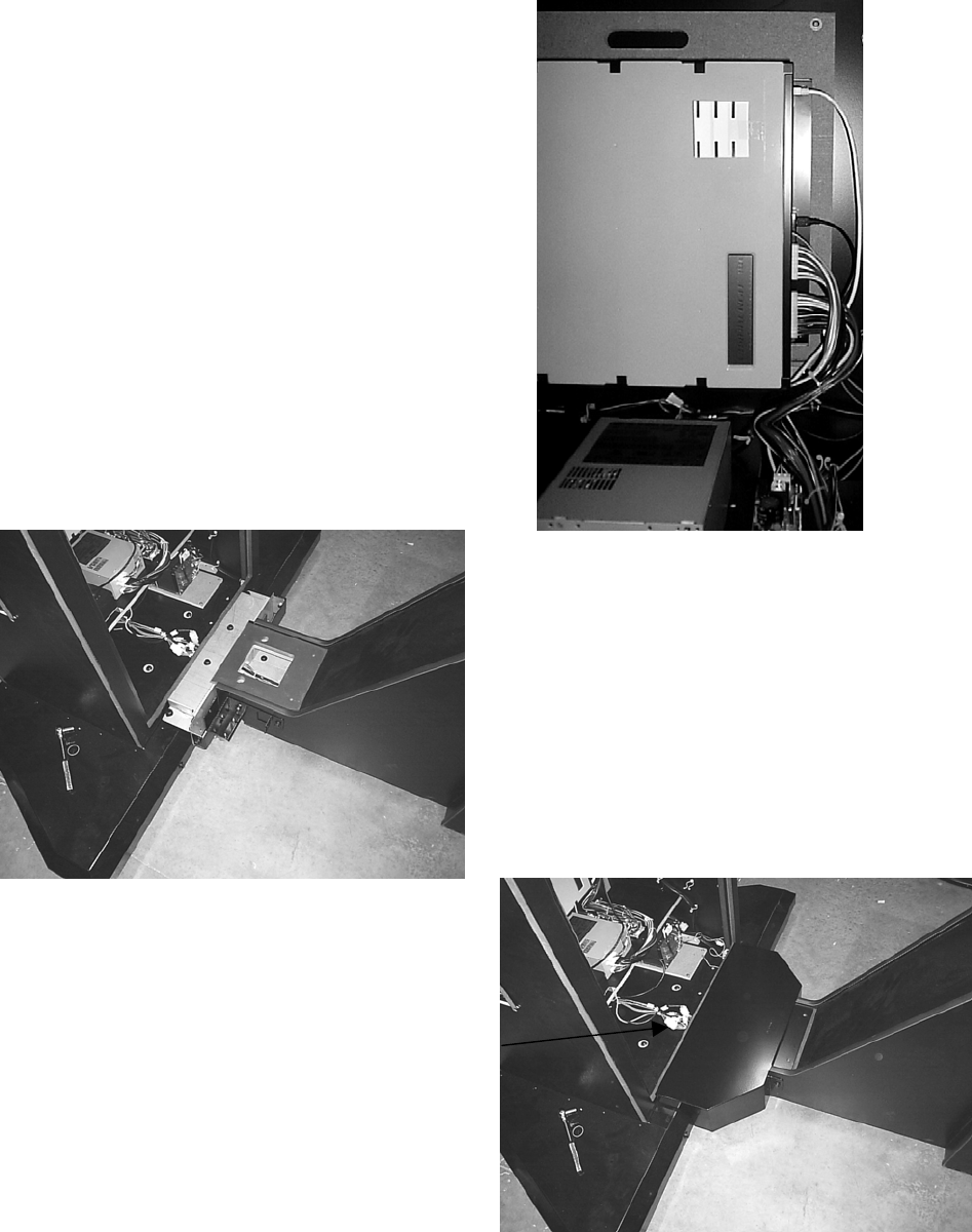
• Feed the 6th and final harness up through
the inside rear of the DLP cabinet and
connect into the USB port on the Lindbergh
CPU as shown in picture (left).
• Secure DLP and GUN Cabinets together
using 2x M8x30 Hex Bolt and 2x M8x65
Hex Bolt
• Place JOINT COVER (HDF-1031UK) over
the joint of the 2 cabinets and re-secure
using 2x M5x16 PAN PAS BLK and 2x
M6x50 HEX BOLT BLK.
• Finally, fit the CABLE COVER over the hole
in the bottom of the cabinet.
14
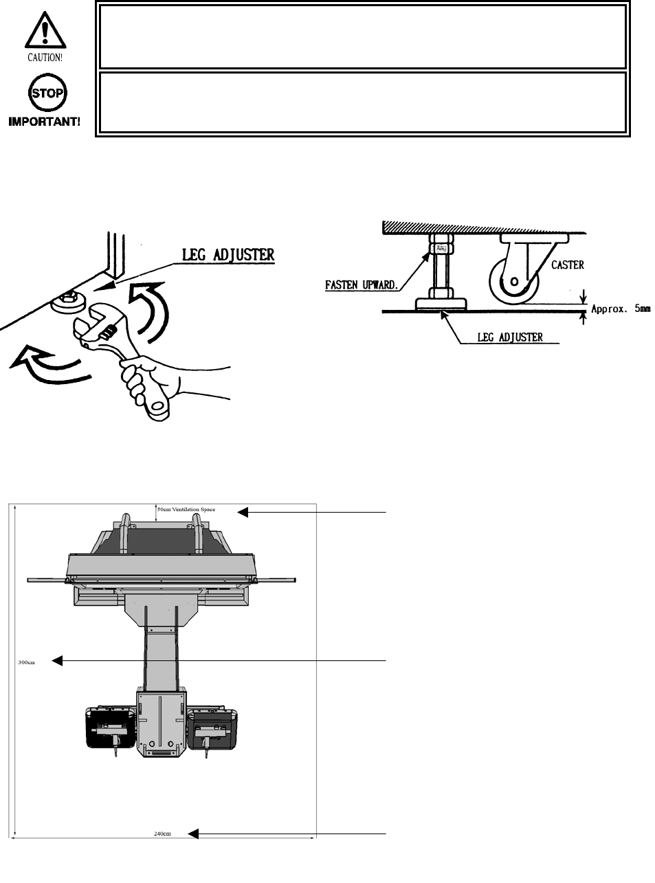
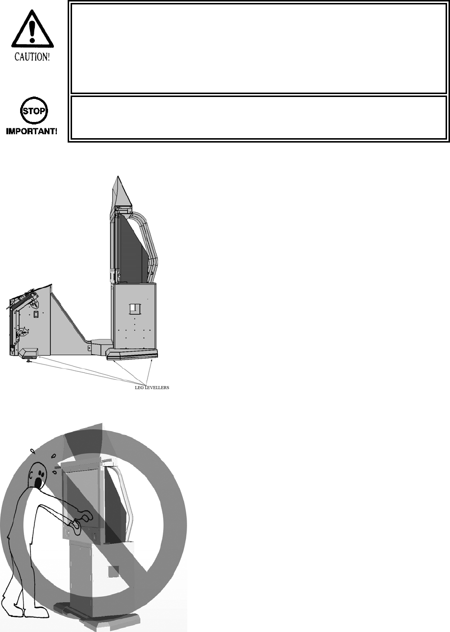
4.5.2. LEG LEVELLING PROCEDURE
STEP 2
• Make sure all of the leg adjusters are in contact with the floor. If they are not the
machine may move and cause injury. This operation requires 2 people.
• This operation should only be carried out by QUALIFIED SERVICE
PERSONNEL.
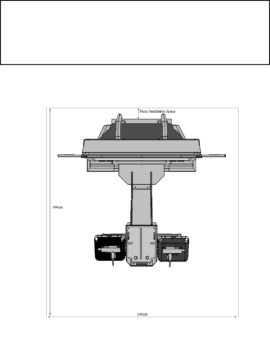
This machine has 8 castors and 6 leg adjusters. When the installation position is decided. Unscrew the leg
adjusters so that they raise each castor a minimum of 5mm from the floor. Make sure the machine is level.
After securing the leg adjuster bolts, fully tighten all bolts temporarily attached in steps 1 above.
Ensure adequate ventilation and operating space is maintained as detailed below.
50cm Ventilation s
p
ace
300cm
240cm
15
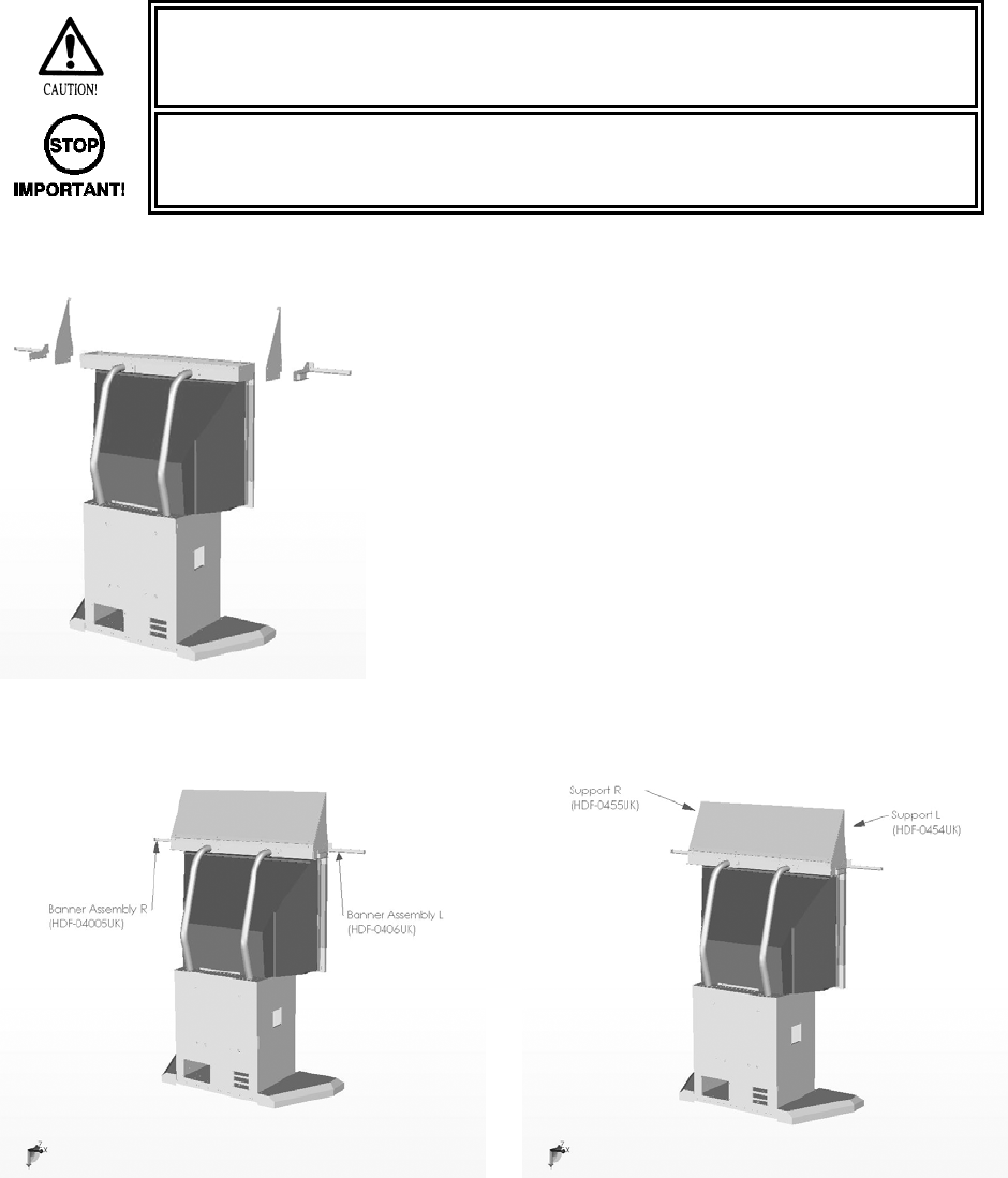
4.5.3. BILLBOARD INSTALLATION PROCEDURE
Step 3
• One person alone cannot perform the installation of the billboard assembly. Seek
assistance before attempting this operation
• This operation should only be carried out by QUALIFIED SERVICE
PERSONNEL.
• Fit the SUPPORTS L&R (HDF-0454UK and
HDF-0455UK) and the BANNER
ASSEMBLY L&R (HDF_0405UK and
HDF_0406UK) to the Billboard Assembly
using 8x M6x20 BLT W/S BLK and 8x M6
WASHERS BLK.

16
• Place the BILLBOARD PLATE (HDF-
0453UK) on the back of the SUPPORTS
L&R and secure along the bottom edge
using 4x M6x12 MCSR PAN W/FS PAS.
• Remove the END CAPS BANNER (HDF-
0406UK) from both BANNER SUPPORTS.
• Slide both BANNERS L&R (HDF-0403UK &
HDF-0404UK) onto the supports and re-
secure the END CAPS BANNER.
17
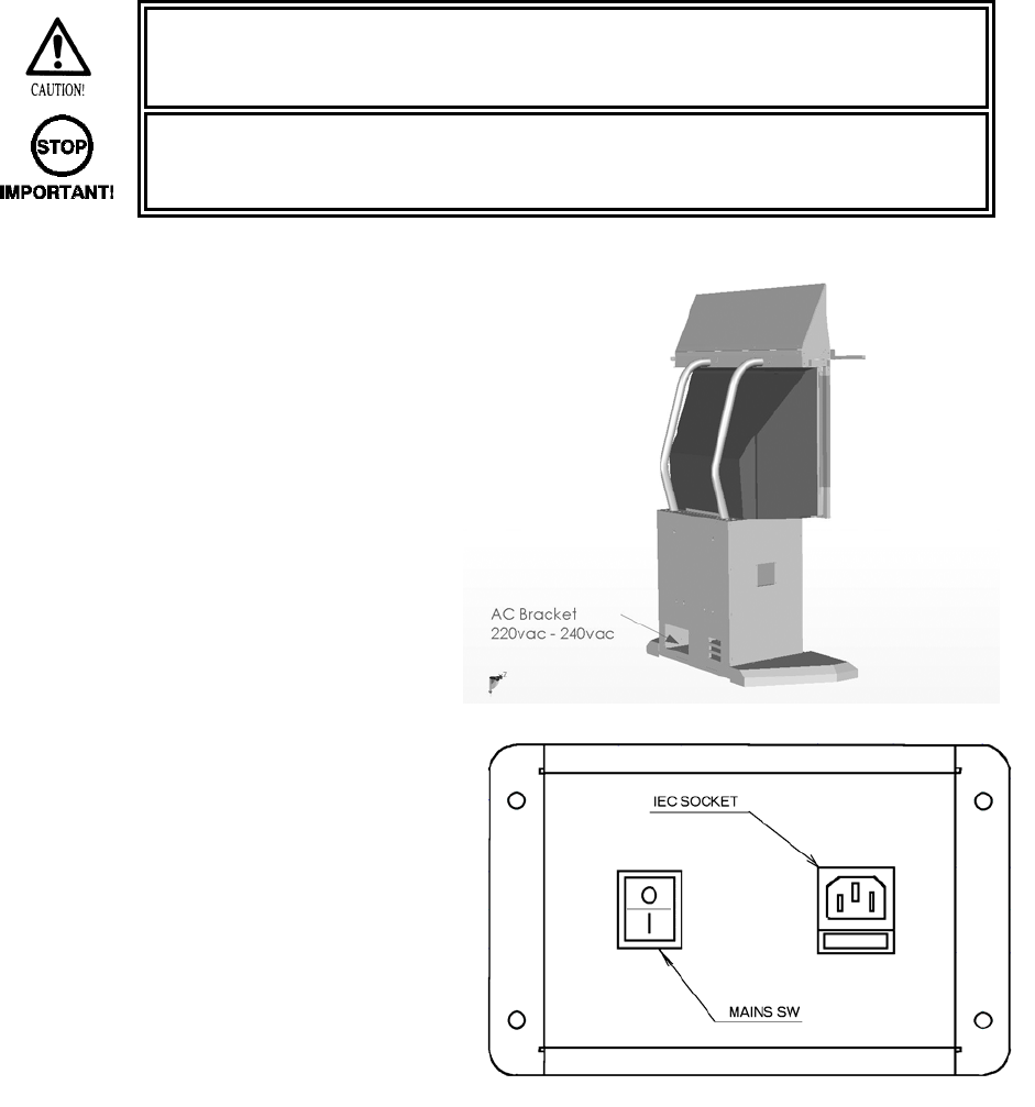
4.5.4. FOR AC WIRING CONNECTION PROCEDURE
Step 5
• Be sure that the machine is not connected to the mains supply before attempting
this operation
• This operation should only be carried out by QUALIFIED SERVICE
PERSONNEL.
• Once the machine has been fully
assembled and fixed into position,
only then is it ready to apply power.
• The socket outlet shall be installed
near the equipment and shall be
easily accessible.
• Insert the IEC plug into the IEC socket
on the rear of the cabinet.
• Insert the mains cord into the wall.
• Switch the power on at the wall.
• Switch on the mains switch located on
the AC Bracket.
18
4.5.5. ASSEMBLY CHECK
• This operation should only be carried out by QUALIFIED SERVICE
PERSONNEL.
In the TEST MODE, ensure that the ASSEMBLY has been assembled correctly and that the CPU is in
working order. In the TEST MODE perform the following tests.
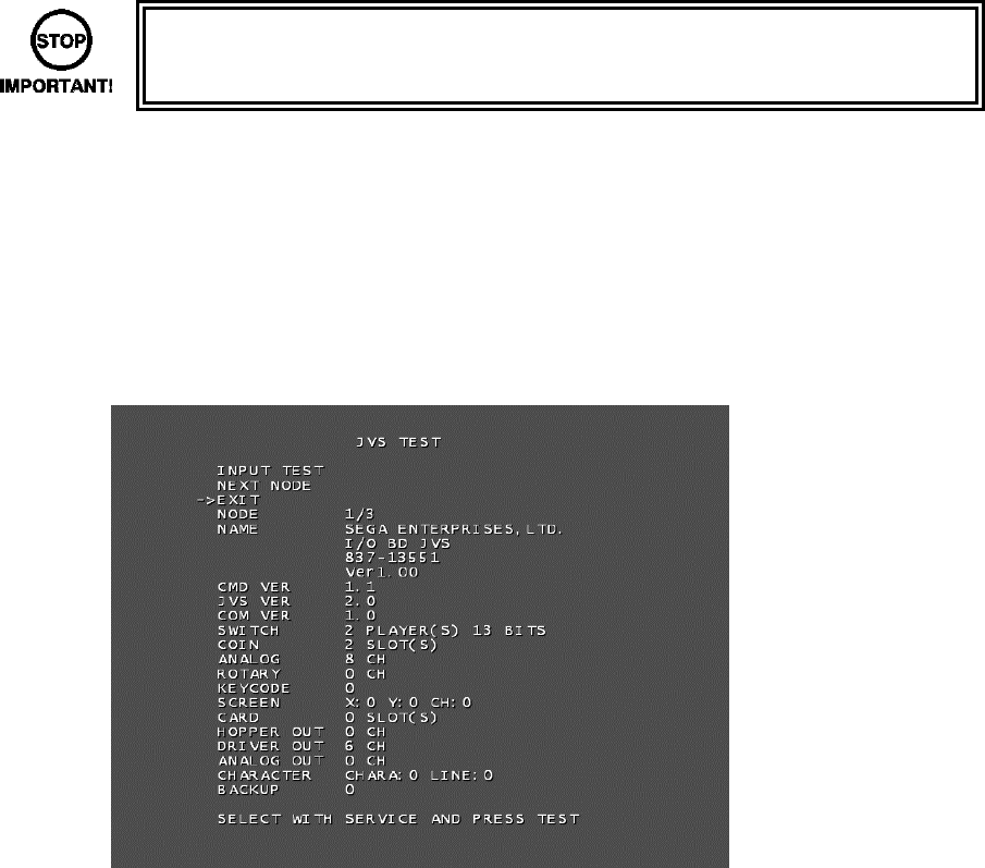
The JVS TEST screen displays information on the connected JVS I/O boards.
Select INPUT TEST to display input data for the currently displayed JVS I/O board. (See “c-1 JVS INPUT
TEST”)
Select NEXT NODE to display information on the next NODE.
If no JVS I/O boards are connected, the message “NO JVS NODE” will be displayed.
The following information is displayed on this screen.
● NODE: The currently displayed NODE number and the total number of connected NODEs
● NAME: ID Code
● CMD VER: Command format version
● JVS VER: JVS standard version
● COM VER: Communication version
● SWITCH: Number of players and number of 1P switches
● COIN: Number of coin slots
● ANALOG: Number of analog channels
● ROTARY: Number of encoders
● KEYCODE: Keycode input active/inactive
● SCREEN: Screen position input (X axis, Y axis, number of channels)
● CARD: Number of card slots
● HOPPER OUT: Number of hoppers
● DRIVER OUT: Number of standard output drivers
● ANALOG OUT: Number of analog output channels
● CHARACTER: Number of characters/lines displayed
● BACKUP: Backup present/absent
Move the cursor to EXIT and press the TEST Button to return to the System Test Menu screen.
19
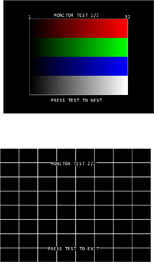
MONITOR TEST
Use MONITOR TEST to check the output of the monitor.
Enter MONITOR TEST and the following color bars will be displayed.
Press the TEST Button and the screen will
change to the following crosshatch screen.
Press the TEST Button to return to the
System Test Menu screen.

20
a. INPUT TEST
Select INPUT TEST to display the following screen and check the status of input devices.
This test should be used periodically to check that each input device is functioning correctly.
The items refer to the following input devices. Input is normal if the display to the right of each item changes
from OFF to ON when each input device is operated.
Everything is functioning correctly if the GUN SPEED X and GUN SPEED Y values change according to the
speed at which the Control Unit (Gun) is moved vertically/horizontally.
Everything is functioning correctly if the word “OUT” to the right of SCREEN IN changes to “IN” when the
gun is pointed at the screen, and the values to the right of GUN X and GUN Y move between 00 to FF.
● START: The player START Buttons.
● GUN TRIGGER: The trigger on the gun.
● GUN BUTTON: The Button on the gun.
● GUN SPEED X: This value changes if gun is shaken on the X axis.
● GUN SPEED Y: This value changes if gun is shaken on the Y axis.
● GUN X: The X axis position on the screen targeted by the gun.
● GUN Y: The Y axis position on the screen targeted by the gun.
● SCREEN IN: Displays if the gun is pointing IN or OUT of the screen.
● SERVICE: The SERVICE Button.
● TEST: The TEST Button.
Press the SERVICE and TEST Buttons simultaneously to return to the Game Test Mode screen.
PRESS TEST AND SERVICE TO EXIT
INPUT TEST
PLAYER1 PLAYER2
START OFF OFF
GUN TRIGGER OFF OFF
GUN BUTTON OFF OFF
GUN SPEED X 7f 7f
GUN SPEED Y 7f 7f
GUN X 00 00
GUN Y 00 00
SCREEN IN OUT OUT
SERVICE OFF
TEST OFF

21
SELECT WITH SERVICE AND PRESS TEST
OUTPUT TEST
START1 LAMP OFF
START2 LAMP OFF
GUN MOTOR1 OFF
GUN MOTOR2 OFF
EXIT
->
b. OUTPUT TEST
Select OUTPUT TEST to display the following screen and check the status of output devices.
This test should be used periodically to check that the lamps are functioning correctly.
Use the SERVICE Button to move the cursor to the desired test item. Press the TEST Button to enter the
selected item’s test.
• Display of GUN MOTOR1 and GUN MOTOR2 options can be turned on or off
using the DIP-SW. For cabinets with vibration motors attached to the Control
Units (Guns), turn on display of the GUN MOTOR1 and GUN MOTOR2 under
DIP-SW settings to alter these settings.
Perform the tests as follows.
● START1 LAMP: Select START1 LAMP and press the TEST Button to turn the option ON.
The player 1 START Button will light up. The lamp will remain on for as long as the TEST Button is held
down.
● START2 LAMP: Select START2LAMP and press the TEST Button to turn the option ON.
The player 2 START Button will light up. The lamp will remain on for as long as the TEST Button is held
down.
● GUN MOTOR1: Select GUN MOTOR1 and press the TEST Button to turn the option ON.
The player 1 gun will begin to vibrate. The vibration will continue for as long as the TEST Button is held
down.
● GUN MOTOR2: Select GUN MOTOR2 and press the TEST Button to turn the option ON.
The player 2 gun will begin to vibrate. The vibration will continue for as long as the TEST Button is held
down.
Move the cursor to EXIT and press the TEST Button to return to the Game Test Mode screen.

22
PRESS TEST TO EXIT
PLAYER1 GUN ADJUSTMENT
←PLEASE SHOOT GRID WITH PLAYER1 GUN
PRESS TEST TO EXIT
PLAYER1 GUN ADJUSTMENT
PLEASE SHOOT GRID WITH PLAYER1 GUN→
c. PLAYER1 GUN ADJUSTMENT/PLAYER2 GUN ADJUSTMENT
This item adjusts the Player 1 gun sight. (This is the same for “PLAYER2 GUN ADJUSTMENT”.)
Select PLAYER1 GUN ADJUSTMENT on the Gun Calibration Setting screen and press the TEST Button.
NOTE: “PLEASE SHOOT GRID WITH PLAYER1 GUN” on the screen will flash.
Follow the on-screen instructions to adjust the gun sight settings. Aim at the mark in the upper left corner
and fire. The mark in the upper left will disappear, and the same mark will be displayed in the lower right
corner.
(Press the TEST Button to return to the Gun Calibration Setting screen.)

23
PRESS TEST TO EXIT
PLAYER1 GUN ADJUSTMENT
↑PLEASE SHOOT GRID WITH PLAYER1 GUN
PLAYER1 GUN ADJUSTMENT
NOW CALCULATING
Aim and fire at the mark to the lower right. The mark to the lower right will disappear, and the same mark
will be displayed in the center.
(Press the TEST Button to return to the Gun Calibration Setting screen.)
Aim and fire at the mark in the center.
“NOW CALCULATING” will be displayed in the center. The screen will automatically switch to the following.

24
TEST : TO MEMORIZE
SERVICE : TO CANCEL
PLAYER1 GUN MARK CHECKING
+OUT OF SCREEN P1+
PLAYER1 GUN ADJUSTMENT
Point the Control Unit (Gun) at the screen and a gun mark will be displayed. Check to make sure that the
gun can aim right up to the edges of the frame.
If the calibration is correct press the TEST Button to save it.
If re-calibration is required press the SERVICE Button. The calibration results will not be saved and you will
return to the Gun Calibration Setting screen.
“OUT OF SCREEN” is displayed when the gun cross is perceived to be out of screen.
Refer to the following procedure when adjusting the sights.
- Line up the concave sight nearest you on the gun so that it is at the height of the horizontal line of the “+”
mark.
- Line up the convex sight at the tip of the gun so that it also lines up with the horizontal line.
- Line up the centers of the tops of the concave and convex sights with the center of the “+” and fire.
25
4.5.6. MOVING THE MACHINE
• When moving the machine, be sure to remove the plug from the power supply.
Moving the machine with the plug inserted can cause the power cord to be
damaged, resulting in a fire or electric shock.
• When moving the machine, retract the leg adjusters fully and ensure the casters
make contact with the floor. During movement pay careful attention so that the
casters or leg adjusters do not damage any other cabling laid on the floor. Such
damage could result in a fire or electric shock.
• This operation should only be carried out by QUALIFIED SERVICE
PERSONNEL.
• Ensure that the LEG LEVELLERS are raised
above the position of the CASTORS before
attempting to move.
• Do not push the machine using the screen as
leverage.
• This can cause damage to the display

26
4.6. FUSES
• Never touch places other than those specified. Touching places other than those
specified can cause electric shock and short circuit. Disconnect the machine from
the supply before attempting the replacement of any fuse.
• FUSES should only be replaced by QUALIFIED SERVICE PERSONNEL.
There are a number of fuses used on this machine to protect the user and the machine from damage. Only
replace the fuse once you have removed the cause of its failure. Detailed below is a list of the fuses used,
their location and if relevant P.C.B. reference:
PART NUMBER LOCATION TYPE & DETAILS QTY
514-5078-2000 WH HDF (60033UK) 2A T CERAMIC 20X5MM 2
514-5078-2000 WH HDF 60029-02UK) 2A T CERAMIC 20X5MM 4
514-5079-10000 XFMR (560-LGBH-UK) 10A T CERAMIC 32X6.3MM 1
514-5090-3000 FL UNIT (390-7001-30UK) 3A T CERAMIC 25X6.3MM 1
514-5078-10000 IEC INLET (EP1387) 10A T CERAMIC 20X5MM 1
Please refer to the DISPLAY service manual for information regarding serviceable fuses.
27
4.7. REPLACEMENT OF FLUORESCENT LAMP AND OTHER LAMPS
• Never touch places other than those specified. Touching places other than those
specified can cause electric shock and short circuit. Disconnect the machine from
the supply before attempting the replacement of any lamp.
• Lamps should only be replaced by QUALIFIED SERVICE PERSONNEL.
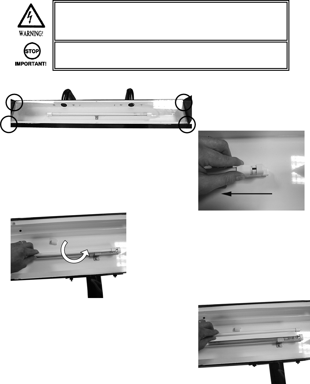
4.7.1. FLUORESCENT LAMP REPLACEMENT BILLBOARD
• TURN OFF THE MACHINE.
• Remove the 4 screws, which
retain the BILLBOARD sheet.
• Lift off the BILLBOARD sheet.
• Slide back the covers located over the ends of the
Fluorescent lamp.
• Carefully twist the lamp to
remove.
• Replace the old lamp with a new lamp.
• Reverse the procedure to reassemble.
28
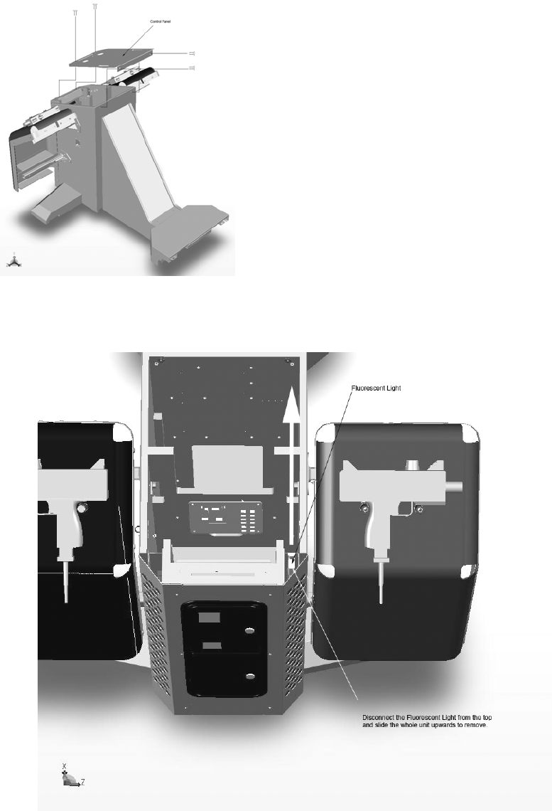
4.7.2. FLUORESCENT LAMP REPLACEMENT GUN CABI
• TURN OF THE MACHINE.
• Remove the four (4) truss head screws that
secure the ASSY CONTROL PANEL to the
Gun Cabinet.
• Lift off the ASSY CONTROL PANEL and
disconnect the Lamp and switch holders
before removing.
• Disconnect the lamp at the top connection point.
• Carefully raise the lamp assembly unit the unit is free from the cabinet.
• Replace the lamp following the instructions for the BILLBOARD LAMP replacement.
Follow the procedure in reverse to reassemble.
29
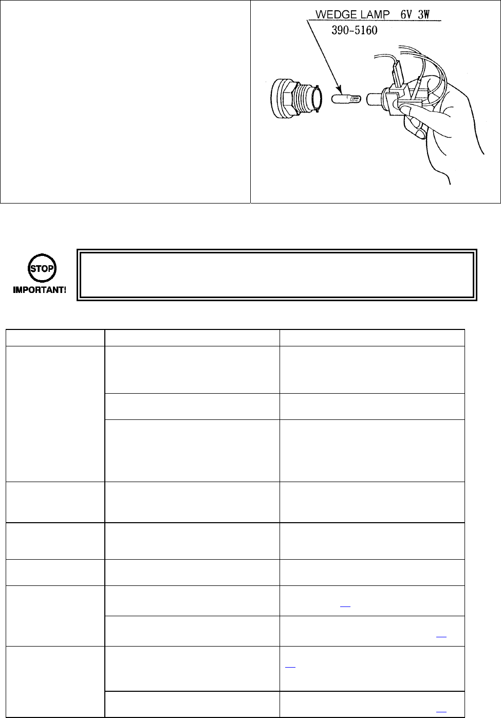
4.7.3. START BUTTON LAMP REPLACEMENT
• Following the procedure in the “Gun Cabinet
Lamp replacement” to remove the ASSY
CONTROL PANEL.
• Locate the ASSY SWITCH with the
defective lamp and twist to remove.
• Pull the bulb from the lamp housing and
replace by push to fit.
• This product uses a LED lamp. The BULB
represented in the image to the right is an
alternative.
• Re-assemble in reverse.
4.8. TROUBLESHOOTING
• These procedures should only be carried out by QUALIFIED SERVICE
PERSONNEL.
If a problem occurs, first check the wiring connections.
PROBLEMS CAUSE COUNTERMEASURES
When the main
switch is turned ON,
the machine is not
activated
The power is not ON. Firmly insert the plug into the outlet.
Incorrect power source/voltage. Make sure that the power supply/voltage
are correct.
AC Unit CIRCUIT PROTECTION
DEVICE (i.e.; fuse) was activated due
to an instantaneous over current.
First, remove the cause of over current
and reinstate the circuit protection device
to its original status.
Then identify the cause of the fault on the
item which caused the over current & fix.
The colour image on
The screen is
incorrect
Incorrect monitor adjustment. Make appropriate adjustments. Refer to
the display service manual.
The on-screen image
of the monitor sways
and/or shrinks
The power source and voltage are not
correct.
Make sure that the power supply and
voltage are correct.
Sound is not emitted Sound volume adjustment is not
correct.
Adjust the volume setting on the display.
Refer to the display service manual
The fluorescent lamp
does not light up
Fluorescent lamp needs replacement Replace the fluorescent lamp. (Please
refer to page 27.)
The connector is disconnected
Check connector connections in the
billboard case. (Please refer to page 27.)
The LEADER lamp
does not light up
The lamp needs replacement.
Replace the lamp. (Please refer to page
28.)
The connector is disconnected Check connector connections in the
billboard case. (Please refer to page 28.)
30
4.9. GAMEBOARD
• Turn off the mains power and remove the power cord before opening the
machine.
• The GAME BOARD should not require any work to be carried out upon it. All
settings and tests can be achieved without access to the GAME BOARD.
• All work to be carried out by QUALIFIED SERVICE PERSONNEL
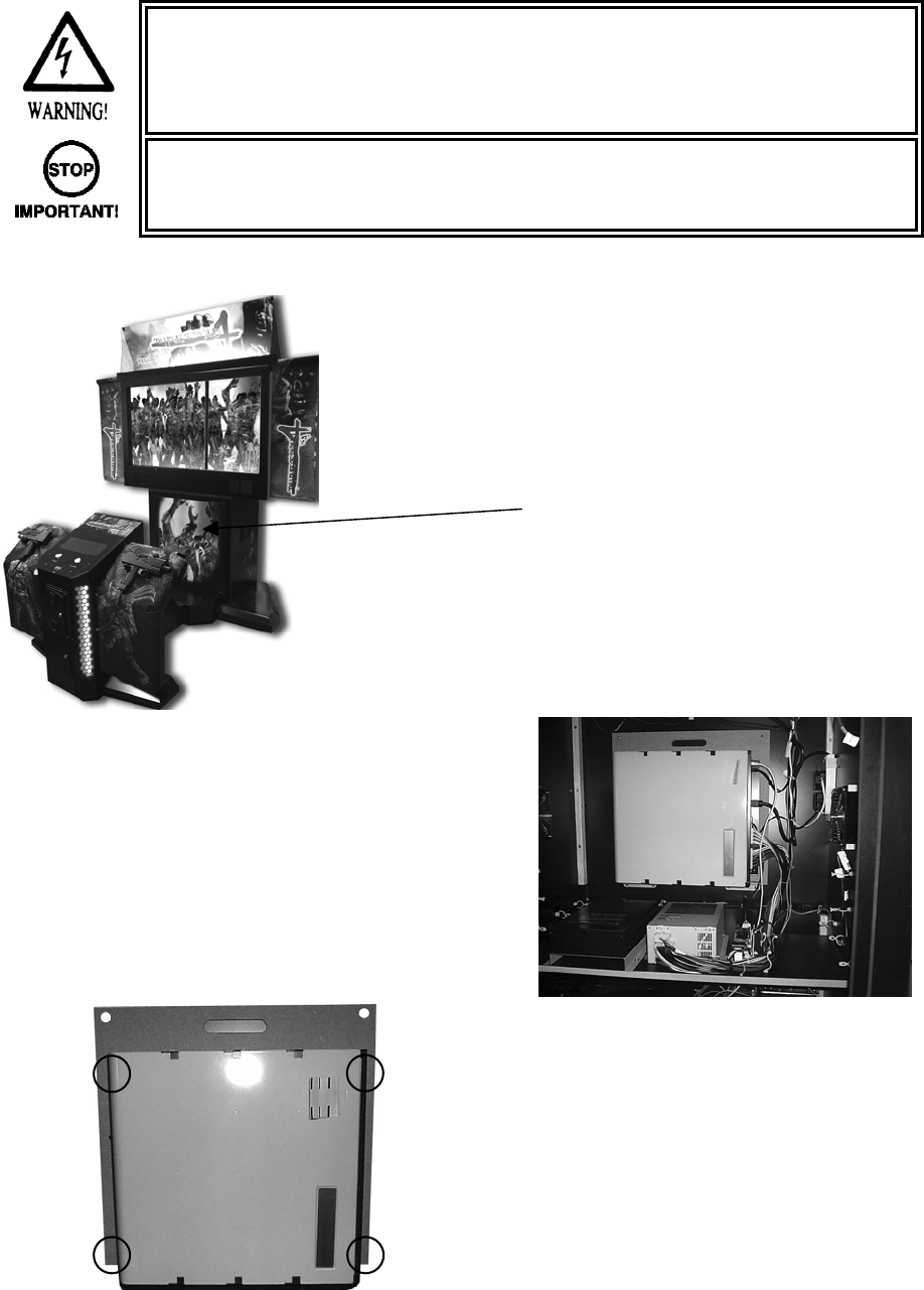
4.9.1. REMOVING THE BOARD
• TURN OFF THE MACHINE.
• Remove the 2x security fixings from the top
corners of the MAIN DOOR.
• Unlock the MAIN DOOR and remove.
• Disconnect ALL cables going to the CPU.
• Remove the 2 top fixings from each corner
of the supporting wood.
• Lift the CPU carefully from its location.
• Remove the 4x screws that retain the CPU
to the wooden base.
• Package the CPU in its original packaging
before despatch.
31
4.10. PERIODIC CHECK AND INSPECTION
The items listed below require periodic check and maintenance to retain the performance of the machine
and ensure safe operation:
• Be sure to check annually to see if the power cords are damaged. The plug is
securely inserted and that there is no dust in the interior of the machine or
between the socket and the power cord. Using the product in an unclean
condition may cause a fire or electric shock.
• Periodic checks should only be carried out by QUALIFIED SERVICE
PERSONNEL.
DESCRIPTION WHAT TO CHECK INTERVAL
CONTROLLERS Check SW
Greasing
Monthly
Every 6 months
MONITOR / PROJECTOR Clean screen
Check adjustment
Weekly
Monthly
GAME BD Memory Test
Game Assignments
Monthly
Monthly
INTERIOR Clean Annually
POWER SUPPLY CORD Check condition Annually
CABINET SURFACE Clean As required
CONTROL PANEL Lamp operation
Check switch operation
Monthly
Monthly
CONTROLLER (GUN) Clean
Check sighting
Check switch operation
As required
Weekly
Monthly
COIN MECHANISM Check SW (If Fitted) Monthly
32
5. HOW TO PLAY
The following explanations apply to the product when functioning properly. If the product operates
differently from the following contents, a fault may have occurred. Immediately look into and eliminate the
cause of the fault to ensure proper operation.
The fluorescent light in the billboard and the cold-cathode tube in the lighting unit are always on whenever
the power is turned on. Demo movies and game rankings are displayed on the screen.
Audio may also be played from speakers on the left and right sides of the main cabinet. However, it is
possible to select whether sound is output or not during Attract Mode through Test Mode settings.
Both the right and left START buttons are integrated with a light. The light flashes when sufficient coins are
inserted for play. The light goes out when the START button is pressed to start the game.
1) Fluorescent lamps are lit.
2) On-screen images are outputted.
3) Sound is emitted.
4) START BUTTON

33
5.1. GAME OUTLINE
• Insert a coin and a credit will be added to the credit indicator below the screen. When enough coins
have been entered for one play, the “INSERT COIN(S)” message below the screen will change to
“PRESS START BUTTON,” and both START buttons will flash.
• NOTE: The maximum number of credits that can be counted at once is “24.” Any coins inserted
after 24 credits have been counted will not be counted as credits, nor will they be refunded.
However, they will be counted as inserted coins on the data display and by the coin meter.
• A player plays on the left (Player 1) or the right (Player 2) by pressing the START button on that
side. Pressing the START button begins the game.
• When the game starts, a demo plays and the stage title is displayed before switching over to game
play.
- Life, loaded bullets remaining and grenades are shown at the bottom left of the screen for
the player on the left (Player 1). Life, loaded bullets remaining and grenades are shown at
the bottom right of the screen for the player on the right (Player 2).
1) Each bullet represents one remaining shot.
2) The number of grenades that can currently be used.
3) Life is displayed as a flame mark. The game ends when life runs out.
4) Credit indicator.
1
2
3
4
34
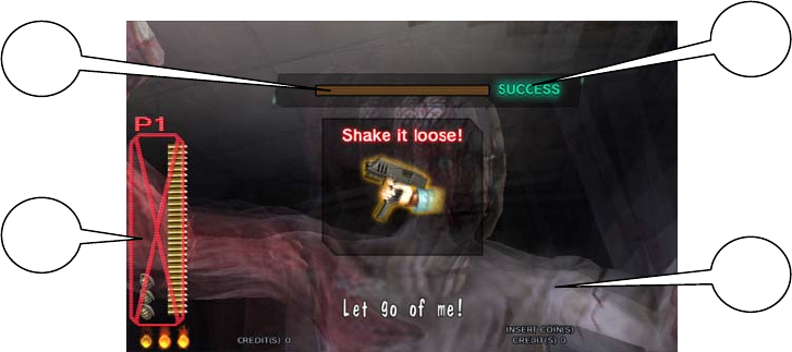
Boss
This is the boss’s life meter.
Defeat the boss by
reducing it to zero.
This is the boss’s cancel
meter.
Stop the boss’s attack by
reducing it to zero.
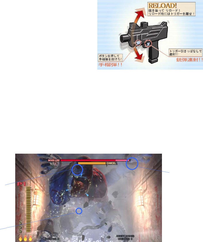
- The gun holds 30 shots. When empty, the message “RELOAD” will appear on the screen. The player can
reload the gun by gently shaking it or by pointing it outside of the screen. The gun can be reloaded by
gently shaking it or pointing it outside of the screen even if bullets remain in the gun.
- Only the displayed number of grenades may be used. This number may be increase by collecting
grenades during each stage. A maximum of 5 grenades may be held at once. Also, if only 2 or less
grenades remain upon clearing a stage, the player will automatically start the next stage with 3 grenades.
(1) RELOAD!
Shake the gun controller to reload!
Release the trigger when reloading!
(2) GRENADE!
Press this button to throw a grenade!
(3) RAPID FIRE!
Hold down the trigger to spray bullets!
- Players can defend themselves against oil drums, rocks
and axes thrown by enemies by shooting them.
- Shooting the background will sometimes cause items to appear. Players grab them by shooting them.
Grabbing items will increase a player’s score or restore life.
- When life reaches zero the game ends.
- A unique boss awaits the players at each stage. The bosses appear different on each stage. Players
defeat a boss by reducing its Life Meter to zero.
In addition, when a boss begins to attack the Cancel Meter appears. Players can stop the boss’s attack by
reducing this meter to zero.
(1)
(2) (3)
35
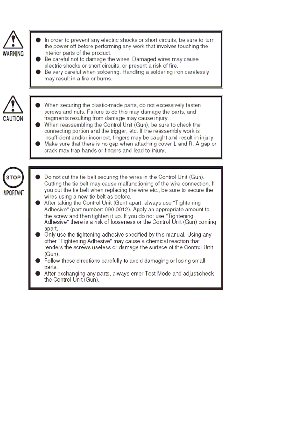
- As the game progresses, players will be faced with enemies grabbing them and attempting to push them
over. To survive this danger, the player must shake the gun controller to fill up the on-screen meter within
the time limit. If the player fails to do so they will take damage, reducing their number of lives, and risk being
pushed over and taking further damage.
1) Shaking the gun controller fills up the on-screen meter.
2) Filling the meter up within the time limit will shake the enemy off.
3) Being grabbed by an enemy.
4) The gun cannot be fired and grenades cannot be used when grabbing an enemy.
• A player can join a game in progress at any time by inserting coins and pressing the START button.
In addition, the START button on the side where no one is playing will continue to flash if enough
credits remain. A second player can join the game by pressing the flashing START button.
• “CONTINUE” is displayed when life drops to zero. A player may continue by inserting sufficient
coins and pressing the START button.
• If upon clearing every stage in the game the player’s score is better than the current top 10, they
may enter their name.
1 2
3
4

36
5.2. ITEMS
Other items can also be found during the game.
“Medical Kit”
Increases life by one.
“Gold Coin”
Increases a player’s score.
“Silk Hat”
Increases a player’s score.
“Mini Magician”
Increases a player’s score.
“Golden Frog”
Increases a player’s score.
“Toy’s Bus”
Increases a player’s score.
37
5.3. PLAY HINTS
● Aim for the head!
Enemies in every stage, aside from boss characters, will lose the most life when shot in the head.
Therefore, shooting enemies accurately in the head is the fastest way to defeat them.
● Choose your favorite route!
Each stage has a number of branching paths. Some branching paths can be simply chosen and some
depend upon certain actions. The key to improving play is to find the route that suits you best!
● Use recovery items to regain lost lives!
Although being attacked by enemies will reduce your remaining lives, each stage also contains items that
will increase remaining lives. Also, upon clearing a stage your performance may award extra lives.
Repeated play and knowledge of the levels will aid in gathering extra lives.
● Use grenades effectively!
As well as the gun, you have grenades in your arsenal. These can cause massive damage to enemies, and
are best used when there are a large number of enemies on screen or at sections you find difficult. Your
number of remaining grenades can be increased by collecting items, and if a stage is cleared with less than
2 grenades remaining you will start the next stage with 3.
● Aim for the boss’ weak spot!
Every stage boss has a weak spot. Shooting this weak spot accurately will help you to avoid boss’ attacks.
However, practice will be required to hit the weak spot accurately whilst the boss is moving.
38
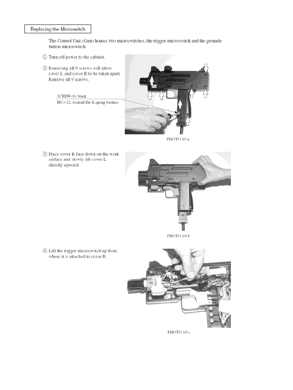
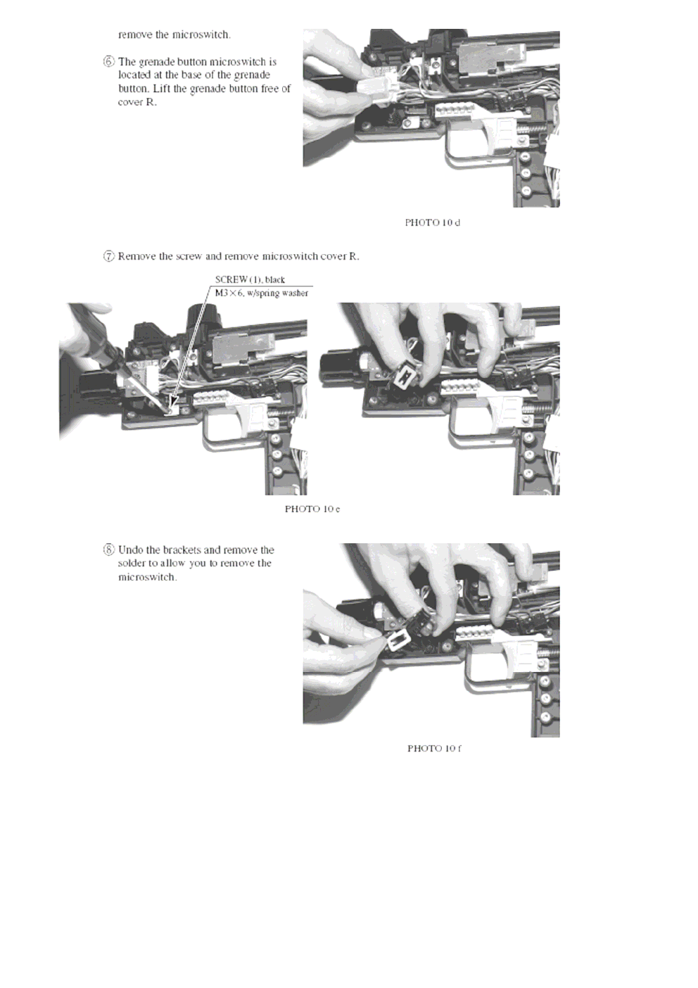
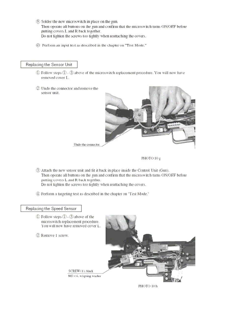
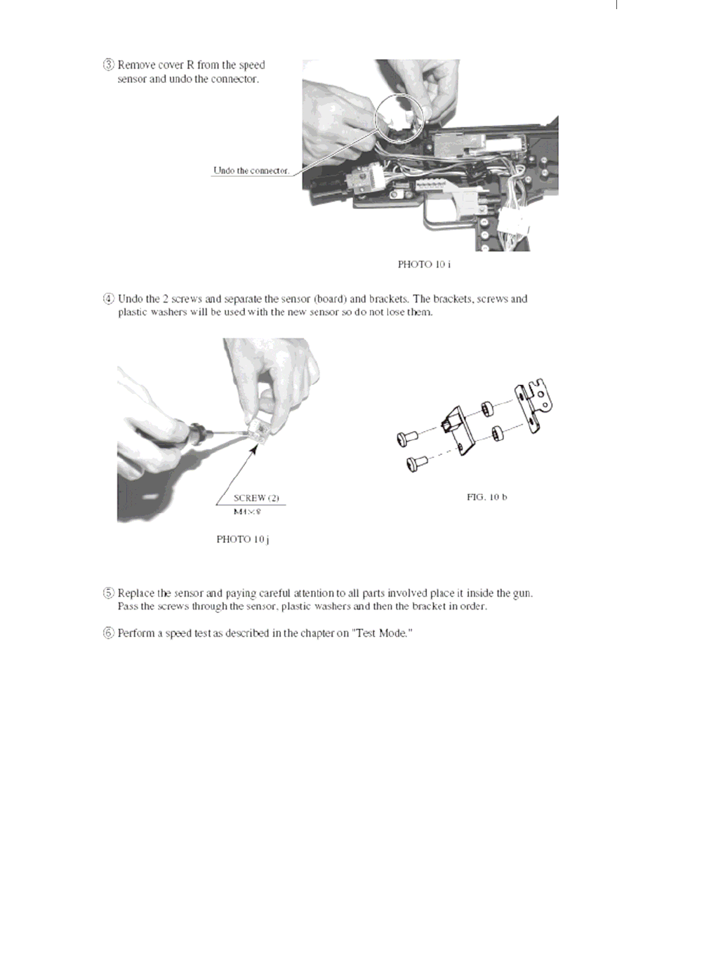
6. CONTROLLER UNIT (GUN)

39
If there appears to be a problem with the gun and adjustment in Test Mode makes no difference,
part of the gun is most likely broken.
Use the following instructions to take the gun apart and replace the broken part.
The exterior casing, comprised of cover L and cover R, must be opened up in order to change
interior parts.
As some internal parts are connected to cover R, work with cover R face down on the working
surface.
FIG. 10 a (Unit Interior)
40
41
42
43

44
7. VOLUME CONTROL
The HOUSE OF THE DEAD 4 52” DELUXE utilises the audio amps and speakers supplied with the LG 52”
REAR PROJECTION DLP.
For this reason the VOLUME CONTROL is no longer positioned on the VTS BOARD. The VOLUME
SETTINGS for this unit is controlled via the LG INFRA RED REMOTE CONTROL (supplied with the DLP).
ZVOL
(This button will increase
the set volume emitted
from the DLP.
The range is from 0 – 100
where 100 represents
HIGH
YVOL
(This button will decrease
the set volume emitted
from the DLP.
The range is from 0 – 100
where 0 represents LOW
45
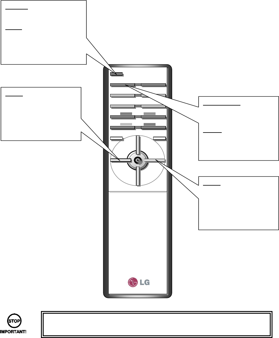
8. REMOTE CONTROL (DLP)
The DLP PROJECTION TV has been manufactured to a SEGA specification and therefore has had a
majority of the features removed. The REMOTE CONTROL supplied with the DLP is used for adjusting the
volume and assigning the INPUT.
This section will highlight the BUTTONS used on the REMOTE CONTROL.
• Be very careful when using the REMOTE CONTROL. Please avoid using any
other buttons that the buttons highlighted in this manual.
ZVOL
(This button will increase
the set volume emitted
from the DLP.
The range is from 0 – 100
where 100 represents
HIGH
YVOL
(This button will decrease
the set volume emitted
from the DLP.
The range is from 0 – 100
where 0 represents LOW
MULTIMEDIA
Selects the output signal.
The video output produced
by LINDBERGH is RGB.
NOTE: No picture will be
displayed if this function is
not set to RGB.
POWER
Turns the DLP unit ON/OFF
or STANDBY.
NOTE: The DLP will take
approximately 30 seconds to
warm up before and outpu
t
is displayed.
46
9. MAINTENANCE INSTRUCTIONS
9.1. EXPLANATION OF TEST AND DATA DISPLAY
Use the switches on the VTS to enter the TEST MODE. This will allow you to carry out post installation and
periodic checks and adjustments. The following section details the function of each of the tests:
• Be very careful about entering TEST MODE. If the machine you wish to test is
linked to other machines, exiting test on your machine will cause a network check
to be carried out. This will disable all other machines linked to it.
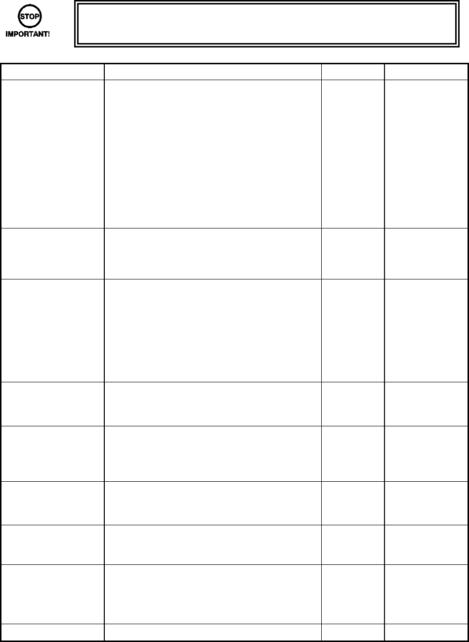
ITEM DESCRIPTION INTERVAL REFERENCES
INSTALLATION OF
THE MACHINE
When the machine is installed perform the
following checks:
• Check to see that each setting is as per the
standard settings input at the time of
shipment.
• In the INPUT TEST mode, check each
switch and V.R.
• In the OUTPUT TEST mode, check each of
the lamps.
• In the MEMORY TEST mode check all of
the IC’s on the IC BD.
Monthly
MEMORY • On the TEST MENU screen choosing the
MEMORY TEST allows self-test to be
performed. In this test RAM & ROM are
tested.
Monthly
PERIODIC CHECKS Periodically perform the following
• MEMORY TEST.
• Ascertain each setting.
• In the INPUT TEST mode, test the control
devices.
• In the OUTPUT TEST mode, check each of
the lamps.
Monthly
CONTROL SYSTEM • In the INPUT TEST mode, check each
switch and V.R.
• Adjust or replace each switch and V.R.
Monthly
MONITOR • In the C.R.T. TEST mode, check to ensure
the monitor is adjusted correctly
• Clean screen (switch off machine and
remove the plug)
Monthly
Weekly
IC BOARD MEMORY TEST
• In the SOUND TEST mode, check the
sound related ROMs
Monthly
DATA CHECK • Check such data as held in the
bookkeeping screens, relating to number
and length of plays
Monthly
EXTERIOR
MAINTENANCE
• Clean surfaces
• Lubricate seat sliders
Note: This appliance shall not be cleaned by a
water jet.
Monthly
COIN MECHANISM • Check switch operation (if fitted) Monthly
47
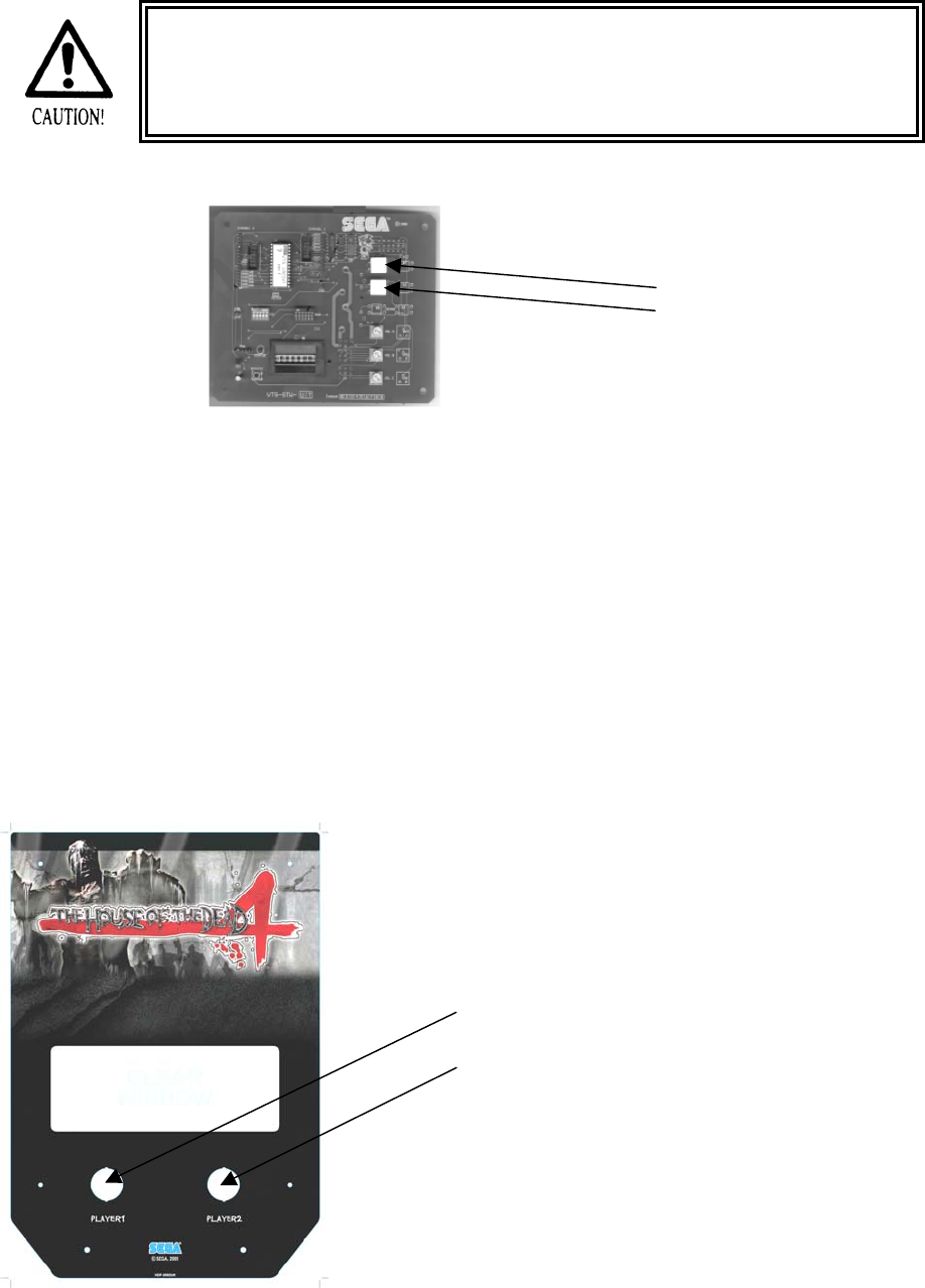
9.1.1. VTS ASSEMBLY
• Do not touch places other than those specified. Touching places not specified
could cause an electric shock or short circuit.
TEST BUTTON
SERVICE BUTTON
Opening the Coin Chute door will reveal the VTS Assembly shown above. The function of each switch is as
follows. The controls on the left affect the 1P cockpit, those on the right the 2P.
TEST BUTTON
(TEST SW)
Used to enter TEST mode. Also has function
during TEST mode. Refer to the later section
detailing TEST mode.
SERVICE BUTTON
(SERVICE SW)
Gives credits without registering on the coin
counter. Also used during TEST mode.
DEMAG <OPTIONAL> NOT USED
VOLUME CONTROL FRONT <OPTIONAL> NOT USED (Please refer to section 6).
VOLUME CONTROL REAR <OPTIONAL> NOT USED (Please refer to section 6).
The control panel switches can also be used in the place of the VTS switches:
PLAYER 1 BUTTON can represent the TEST BUTTON
within the TEST MODE only.
PLAYER 2 BUTTON can represent the SERVICE
BUTTON within the TEST MODE only.
48
9.1.2. SYSTEM TEST MODE
System Test Mode can be used to check the information or the operation of the LINDBERGH board, adjust
Monitor colour, and perform coin/credit settings.
• When setting changes are made within TEST MODE, be sure to exit from TEST
MODE using the exit options. If you turn the power off and then on without having
exited correctly the changes you made will not take effect.
• Make sure that the control panel support is fixed firmly in place before performing
any operations. Closing the control panel with the support loose may lead to
accidents.
• Be careful not to trap your fingers when closing the control panel.
• The details of changes to Test Mode settings are saved when you exit from Test
Mode by selecting EXIT from the SYSTEM TEST MENU. Be careful because if
the power is turned off before that point, changes to the settings will be lost.
Use with the specified settings. If settings other than those specified are used,
inappropriate operations or malfunction may occur.
Press the TEST Button after powering on the unit to display the following SYSTEM TEST MENU.
Use the SERVICE Button to move the cursor to the desired test item. Press the TEST Button to enter the
selected item.
Press the TEST Button when GAME TEST MODE is selected to change to the Test Menu specific to this
game.
Refer to the section “9-3 GAME TEST MODE.”
After the test is complete, move the cursor to EXIT and press the TEST Button to return to the Game
Advertisement screen.
SELECT WITH SERVICE AND PRESS TEST
SYSTEM TEST MENU
->
…………………………… a
…………………………… b
…………………………… c
…………………………… d
…………………………… e
…………………………… f
…………………………… g
…………………………… h
…………………………… i
SYSTEM INFORMATION
STORAGE INFORMATION
JVS TEST
MONITOR TEST
SPEAKER TEST
COIN ASSIGNMENTS
CLOCK SETTING
NETWORK SETTING
GAME TEST MODE
EXIT
49
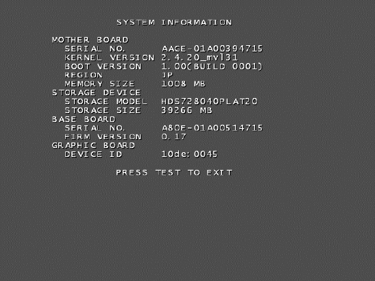
a. SYSTEM INFORMATION
The SYSTEM INFORMATION screen displays system information.
The following information is displayed on this screen.
● MOTHER BOARD
- SERIAL NO.: The serial number of the game board.
- KERNEL VERSION: The system’s OS version.
- BOOT VERSION: The boot program version.
- REGION: The region setting.
- MEMORY SIZE: The onboard memory size.
● STORAGE DEVICE: The total capacity of the program installer device.
- STORAGE MODEL: (Displayed in the above photo but not actually displayed by the product)
- STORAGE SIZE: The total capacity of the program installer device.
● BASE BOARD
- SERIAL NO.: The serial number.
- FIRM VERSION: The firmware version.
● GRAPHIC BOARD
DEVICE ID: The graphic board’s ID.
Press the TEST Button to return to the System Test Menu screen.

50
b. STORAGE INFORMATION
The STORAGE INFORMATION screen displays information on the game contained within the program
installer device. This screen is also used when uninstalling the game contained within the program installer
device.
Until preparations to launch the game are complete, a “now checking” screen will be displayed and uninstall
cannot be performed. If the program installer device does not contain any game data, the game information
will be displayed in grey and uninstall cannot be performed.
The following information is displayed on this screen.
● GAME TITLE
● GAME ID
● PROGRAM TYPE
● INSTALLED IMAGE LIST
- IMAGE NUMBER
- GAME ID
-VERSION
- DATE OF RELEASE
Move the cursor to EXIT and press the TEST Button to return to the System Test Menu screen.
51
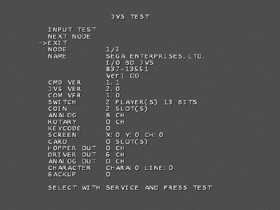
c. JVS TEST
The JVS TEST screen displays information on the connected JVS I/O boards.
Select INPUT TEST to display input data for the currently displayed JVS I/O board. (See “c-1 JVS INPUT
TEST”)
Select NEXT NODE to display information on the next NODE.
If no JVS I/O boards are connected, the message “NO JVS NODE” will be displayed.
The following information is displayed on this screen.
● NODE: The currently displayed NODE number and the total number of connected NODEs
● NAME: ID Code
● CMD VER: Command format version
● JVS VER: JVS standard version
● COM VER: Communication version
● SWITCH: Number of players and number of 1P switches
● COIN: Number of coin slots
● ANALOG: Number of analog channels
● ROTARY: Number of encoders
● KEYCODE: Keycode input active/inactive
● SCREEN: Screen position input (X axis, Y axis, number of channels)
● CARD: Number of card slots
● HOPPER OUT: Number of hoppers
● DRIVER OUT: Number of standard output drivers
● ANALOG OUT: Number of analog output channels
● CHARACTER: Number of characters/lines displayed
● BACKUP: Backup present/absent
Move the cursor to EXIT and press the TEST Button to return to the System Test Menu screen.
52
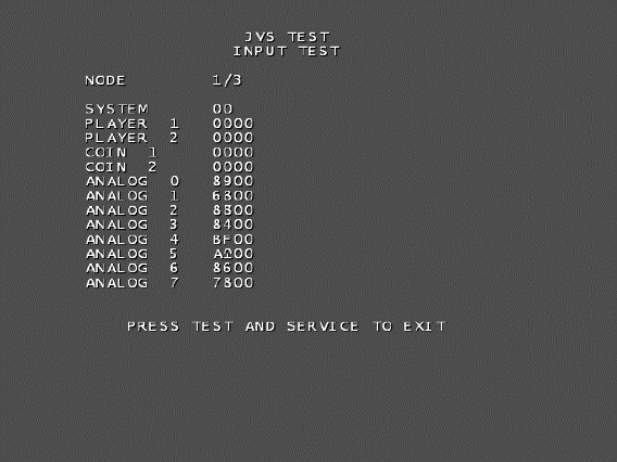
c-1. JVS INPUT TEST
Use the JVS INPUT TEST to test the JVS input.
The hexadecimal input information from the JVS I/O board will be displayed in real time.
The following information is displayed on this screen.
● SYSTEM: System switch input data
● PLAYER: Player number and player switch input data
● COIN: Slot number and coin input data
● ANALOG: Channel number and analog input data
● ROTARY: Rotary number and rotary input data
Press the SERVICE and TEST Buttons simultaneously to return to the JVS Test screen.
53
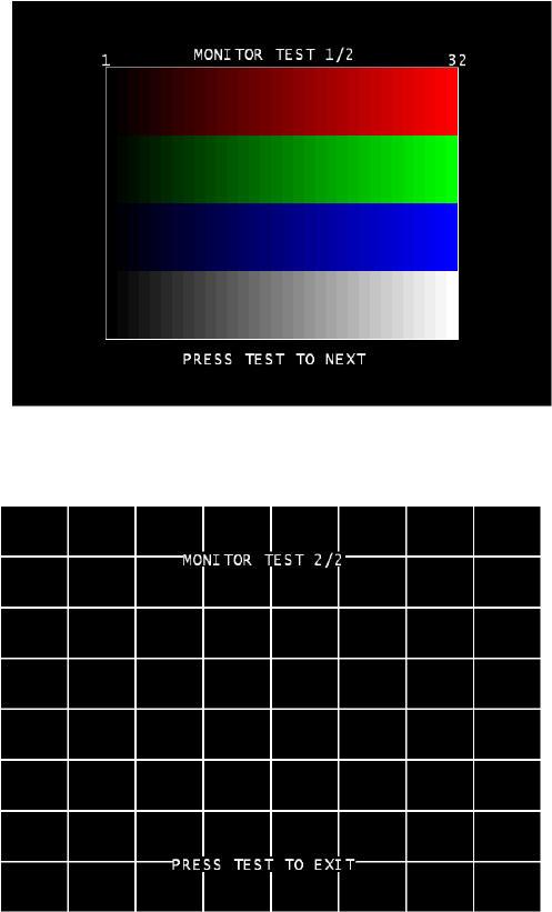
d. MONITOR TEST
Use MONITOR TEST to check the output of the monitor.
Enter MONITOR TEST and the following color bars will be displayed.
Press the TEST Button and the screen will change to the following crosshatch screen.
Press the TEST Button to return to the System Test Menu screen.
54
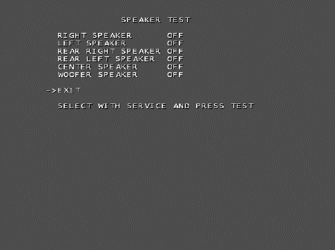
e. SPEAKER TEST
Use SPEAKER TEST to check the output of each speaker by having them each emit a test sound.
Select each speaker with the cursor and press the TEST Button to turn that speaker ON or OFF.
When set to ON a test sound will be emitted from that speaker.
It is possible to set multiple speakers to emit the test sound at the same time.
If the stipulated sound card is not present this test screen will not display this menu.
The speakers available to test are as follows.
● RIGHT SPEAKER
● LEFT SPEAKER
● REAR RIGHT SPEAKER
● REAR LEFT SPEAKER
● CENTER SPEAKER
● WOOFER SPEAKER
Move the cursor to EXIT and press the TEST Button to return to the System Test Menu screen.
55
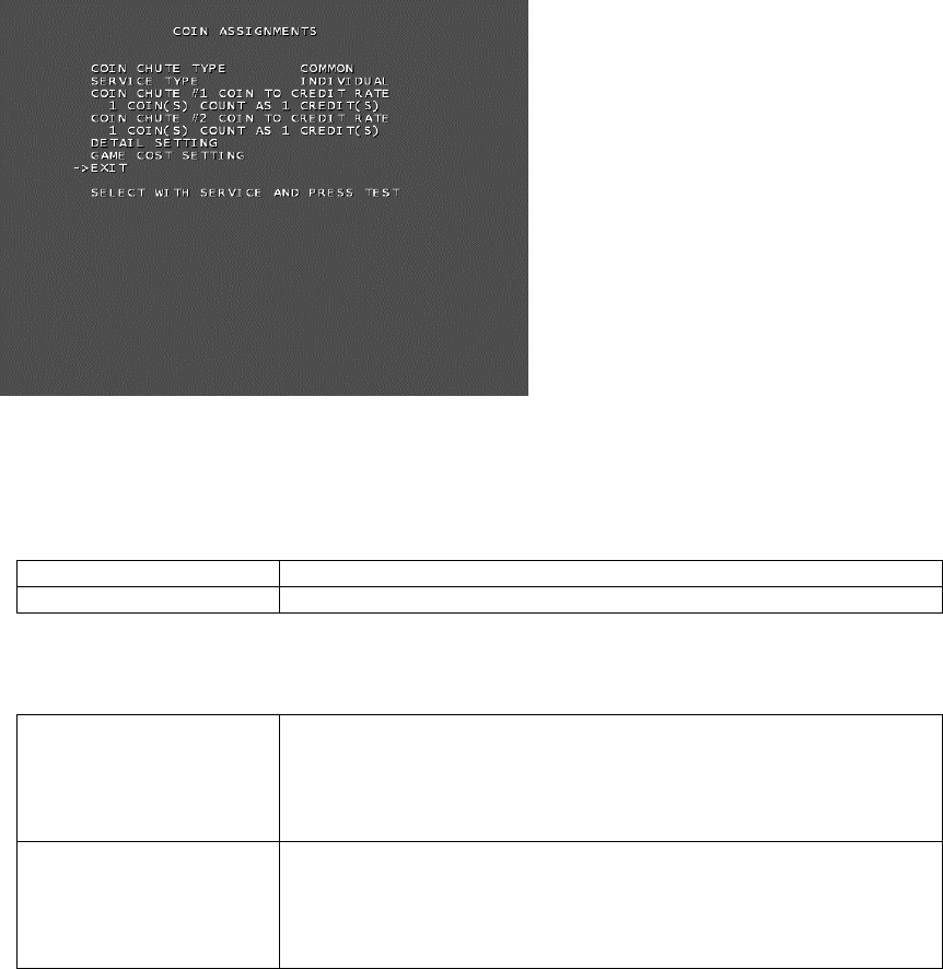
f. COIN ASSIGNMENTS
Use COIN ASSIGNMENTS to alter the credit settings.
The game will award players the number of credits determined here. Settings will only be saved if they have
been changed.
Changing the credit settings will also clear the current inserted coins value.
If no baseboard is present, this option will not appear on the main menu.
The following settings must be set as shown below for this product.
● COIN CHUTE TYPE: COMMON
● SERVICE TYPE: COMMON
………. f-1
………. f-2
………. f-3
………. f-4
………. f-5
………. f-6
The following information is displayed on this screen.
f-1. COIN CHUTE TYPE
COMMON Allow all credits to be used by all players.
INDIVIDUAL Treat each player’s credits individually.
f-2. SERVICE TYPE (Service Button Type)
COMMON
When the COIN CHUTE TYPE is set to COMMON, the number of
credits available to all players will increase by 1.
---------------------------------------------------------------------------------------
When the COIN CHUTE TYPE is set to INDIVIDUAL, each
player’s credits will increase by 1.
INDIVIDUAL
When the COIN CHUTE TYPE is set to COMMON, the number of
credits available to all players will increase by 1.
---------------------------------------------------------------------------------------
When the COIN CHUTE TYPE is set to INDIVIDUAL, the player
corresponding to the SERVICE Button’s credits will increase by 1.
56
f-3. COIN CHUTE #1 COIN TO CREDIT RATE (Coin and credit conversion rate 1)
1 COIN(S) COUNT AS 1 CREDIT(S) 1 coin counts as 1 credit
2 COIN(S) COUNT AS 1 CREDIT(S) 2 coins count as 1 credit
3 COIN(S) COUNT AS 1 CREDIT(S) 3 coins count as 1 credit
4 COIN(S) COUNT AS 1 CREDIT(S) 4 coins count as 1 credit
5 COIN(S) COUNT AS 1 CREDIT(S) 5 coins count as 1 credit
1 COIN(S) COUNT AS 2 CREDIT(S) 1 coin counts as 2 credits
1 COIN(S) COUNT AS 3 CREDIT(S) 1 coin counts as 3 credits
1 COIN(S) COUNT AS 4 CREDIT(S) 1 coin counts as 4 credits
1 COIN(S) COUNT AS 5 CREDIT(S) 1 coin counts as 5 credits
FREE PLAY Free play (no coins required)
DETAIL SETTING More detailed settings
f-4. COIN CHUTE #2 COIN TO CREDIT RATE (Coin and credit conversion rate 2)
(Can only be set when the COIN CHUTE TYPE is set to COMMON and the COIN setting for the COIN
CHUTE #1 COIN TO CREDIT RATE is set to “1”)
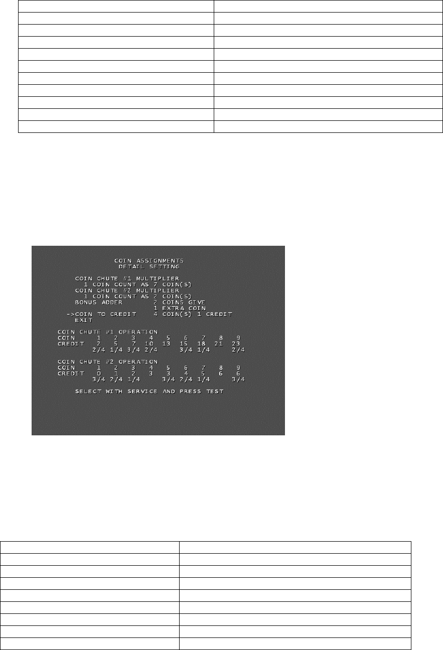
f-5. DETAIL SETTING
The COIN ASSIGNMENTS DETAIL SETTING screen allows more detailed settings that cannot be
performed on the Coin Setting screen to be performed.
The following information is displayed on this screen.
● COIN CHUTE #1 MULTIPLIER: Coin conversion rate for #1 (How many coins 1 inserted coin
counts for)
● COIN CHUTE #2 MULTIPLIER: Coin conversion rate for #2 (How many coins 1 inserted coin
counts for)
● BONUS ADDER: Use of a bonus coin
NO BONUS ADDER No bonus coin given
2 COINS GIVE 1 EXTRA COIN 2 coins inserted successively award 1 bonus coin
3 COINS GIVE 1 EXTRA COIN 3 coins inserted successively award 1 bonus coin
4 COINS GIVE 1 EXTRA COIN 4 coins inserted successively award 1 bonus coin
5 COINS GIVE 1 EXTRA COIN 5 coins inserted successively award 1 bonus coin
6 COINS GIVE 1 EXTRA COIN 6 coins inserted successively award 1 bonus coin
7 COINS GIVE 1 EXTRA COIN 7 coins inserted successively award 1 bonus coin
8 COINS GIVE 1 EXTRA COIN 8 coins inserted successively award 1 bonus coin
9 COINS GIVE 1 EXTRA COIN 9 coins inserted successively award 1 bonus coin
● COIN TO CREDIT: The number of coins to number of credits conversion rate.
Move the cursor to EXIT and press the TEST Button to return to the Coin Assignments screen.
57
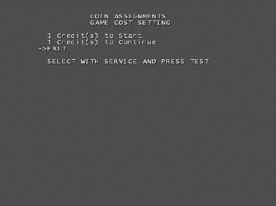
f-6. GAME COST SETTING
Use the COIN ASSIGNMENTS GAME COST SETTING screen to set the cost (number of required credits)
that the game program will use to determine if there are enough credits to play the game.
A total of 8 game costs can be defined. The game cost is defined by the BOOT ID, and when the second
boot recognizes the game, the game cost defined by the BOOT ID will be displayed.
If the game is not recognized, the default game cost will be displayed.
Move the cursor to EXIT and press the TEST Button to return to the Coin Assignments screen.
58
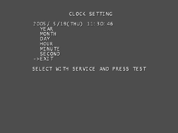
g. CLOCK SETTING
Use CLOCK SETTING to set the date and time.
Use the SERVICE Button to move the cursor to the category that you wish to change and press the TEST
Button to increase that value. Holding the TEST Button down will make the value continuously increase.
Changes will come into effect when you exit.
Move the cursor to EXIT and press the TEST Button to return to the System Test Menu screen.

59
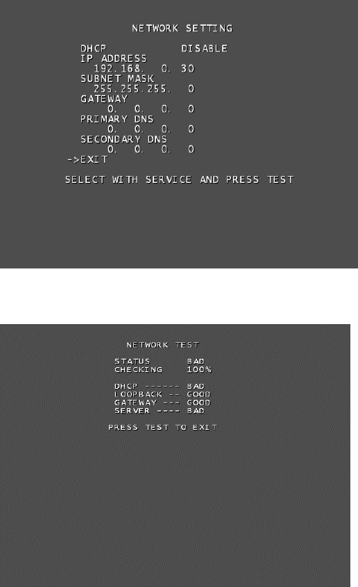
h. NETWORK SETTING
Use NETWORK SETTING to determine network settings or to test the network.
This product does not use the network function. You must use the following factory settings.
● NETWORK TYPE: MAIN
● MAIN NETWORK: No need to set.
The following information is displayed on this screen.
● NETWORK TYPE: Sets the type of network to use.
● MAIN NETWORK: Sets the onboard LAN.
● NETWORK TEST: Performs a network test.
Move the cursor to EXIT and press the TEST Button to return to the System Test Menu screen.
60
Select a category on the NETWORK SETTING (Setting Menu) and the following screen will be displayed.
However, since this product does not use network function, this manual does not contain instructions for
performing network settings or tests.
NETWORK SETTING Screen
NETWORK TEST Screen
i. GAME TEST MODE
Opens the Game Test Mode, allowing game specific settings and tests to be performed.
After starting the game, this option will be displayed in grey until preparations are complete. Select the
Game Test Mode option then select EXIT to begin the game test.
61
………………………… a
………………………… b
………………………… c
………………………… d
………………………… e
………………………… f
………………………… g
9.1.3. GAME TEST MODE
• When setting changes are made within TEST MODE, be sure to exit from TEST
MODE using the exit options. If you turn the power off and then on without having
exited correctly the changes you made will not take effect.
Game Test Mode allows game settings to be altered, Control Units (Guns) to be calibrated and game data
to be checked.
Select GAME TEST MODE from the System Test Menu screen to display the Game Test Mode screen as
follows.
Use the SERVICE Button to move the cursor to the desired test item. Press the TEST Button to enter the
selected item’s test.
Performs test, adjustments and settings for each of the Game Test Mode screen items below.
a. INPUT TEST: Tests each input device used in the game.
b. OUTPUT TEST: Tests each output device used in the game.
c. GAME ASSIGNMENTS: Adjusts game settings.
d. GUN CALIBRATION SETTING: Performs sight settings for the game's gun.
e. GUN SPEED SETTING: Sets the speed volume for the game’s gun.
f. BOOKKEEPING: View all recorded game data.
g. BACKUP DATA CLEAR: Erase all game records.
After selecting an item, read the explanations below regarding operation.
After performing tests and adjustments, return to the Game Test Mode screen, select EXIT and press the
TEST Button. You will return to the System Test Menu screen.
Move the cursor to EXIT on System Test Menu screen and press the TEST Button to return to the Game
Play screen.
SELECT WITH SERVICE AND PRESS TEST
GAME TEST MODE
INPUT TEST
OUTPUT TEST
GAME ASSIGNMENTS
GUN CALIBRATION SETTING
GUN SPEED SETTING
BOOKKEEPING
BACKUP DATA CLEAR
EXIT
->

62
a. INPUT TEST
Select INPUT TEST to display the following screen and check the status of input devices.
This test should be used periodically to check that each input device is functioning correctly.
The items refer to the following input devices. Input is normal if the display to the right of each item changes
from OFF to ON when each input device is operated.
Everything is functioning correctly if the GUN SPEED X and GUN SPEED Y values change according to the
speed at which the Control Unit (Gun) is moved vertically/horizontally.
Everything is functioning correctly if the word “OUT” to the right of SCREEN IN changes to “IN” when the
gun is pointed at the screen, and the values to the right of GUN X and GUN Y move between 00 to FF.
● START: The player START Buttons.
● GUN TRIGGER: The trigger on the gun.
● GUN BUTTON: The Button on the gun.
● GUN SPEED X: This value changes if gun is shaken on the X axis.
● GUN SPEED Y: This value changes if gun is shaken on the Y axis.
● GUN X: The X axis position on the screen targeted by the gun.
● GUN Y: The Y axis position on the screen targeted by the gun.
● SCREEN IN: Displays if the gun is pointing IN or OUT of the screen.
● SERVICE: The SERVICE Button.
● TEST: The TEST Button.
Press the SERVICE and TEST Buttons simultaneously to return to the Game Test Mode screen.
PRESS TEST AND SERVICE TO EXIT
INPUT TEST
PLAYER1 PLAYER2
START OFF OFF
GUN TRIGGER OFF OFF
GUN BUTTON OFF OFF
GUN SPEED X 7f 7f
GUN SPEED Y 7f 7f
GUN X 00 00
GUN Y 00 00
SCREEN IN OUT OUT
SERVICE OFF
TEST OFF

63
SELECT WITH SERVICE AND PRESS TEST
OUTPUT TEST
START1 LAMP OFF
START2 LAMP OFF
EXIT
->
b. OUTPUT TEST
Select OUTPUT TEST to display the following screen and check the status of output devices.
This test should be used periodically to check that the lamps are functioning correctly.
Use the SERVICE Button to move the cursor to the desired test item. Press the TEST Button to enter the
selected item’s test.
[For Overseas Other than Europe]
Perform the tests as follows.
● START1 LAMP: Select START1 LAMP and press the TEST Button to turn the option ON. The
player 1 START Button will light up. The lamp will remain on for as long as the TEST Button is held down.
● START2 LAMP: Select START2 LAMP and press the TEST Button to turn the option ON. The
player 2 START Button will light up. The lamp will remain on for as long as the TEST Button is held down.
Move the cursor to EXIT and press the TEST Button to return to the Game Test Mode screen.

64
SELECT WITH SERVICE AND PRESS TEST
OUTPUT TEST
START1 LAMP OFF
START2 LAMP OFF
GUN MOTOR1 OFF
GUN MOTOR2 OFF
EXIT
->
• Display of GUN MOTOR1 and GUN MOTOR2 options can be turned on or off
using the DIP-SW. For cabinets with vibration motors attached to the Control
Units (Guns), turn on display of the GUN MOTOR1 and GUN MOTOR2 under
DIP-SW settings to alter these settings.
Perform the tests as follows.
● START1 LAMP: Select START1 LAMP and press the TEST Button to turn the option ON.
The player 1 START Button will light up. The lamp will remain on for as long as the TEST Button is held
down.
● START2 LAMP: Select START2LAMP and press the TEST Button to turn the option ON.
The player 2 START Button will light up. The lamp will remain on for as long as the TEST Button is held
down.
● GUN MOTOR1: Select GUN MOTOR1 and press the TEST Button to turn the option ON.
The player 1 gun will begin to vibrate. The vibration will continue for as long as the TEST Button is held
down.
● GUN MOTOR2: Select GUN MOTOR2 and press the TEST Button to turn the option ON.
The player 2 gun will begin to vibrate. The vibration will continue for as long as the TEST Button is held
down.
Move the cursor to EXIT and press the TEST Button to return to the Game Test Mode screen.

65
c. GAME ASSIGNMENTS
Select GAME ASSIGNMENTS to display the current game settings and make changes.
Changes to settings are not enabled until Game Assignments is exited. After changing settings, be sure to
exit the Test Mode.
Use the SERVICE Button to move the cursor to the desired test item. Press the TEST Button to enter the
selected item’s test.
Perform the following settings for each item.
● GAME DIFFICULTY:
Set the level of difficulty to one of five levels; VERY EASY -> MEDIUM EASY ->NORMAL ->
MEDIUM HARD -> VERY HARD.
● LIFE SETTING INITIAL LIFE
The number of lives the player will start the game with. Can be set between 1 and 9. However,
cannot be set higher than the MAX LIFE setting.
● LIFE SETTING MAX LIFE:
The maximum number of lives a player may have. Can be set between 1 and 9.
● BLOOD COLOR:
You can set the color of blood to one of two settings; RED or BROWN.
● VIOLENCE:
You can set the level of damage for the enemies to one of two settings; NORMAL or MILD. When
set to MILD, the violence of enemy deaths will be toned down.
● ADVERTISE SOUND:
You can set the Attract Mode (Advertise) sound to ON or OFF.
After changing the settings, select EXIT and press the TEST Button to return to the Game Test Mode
screen.
SELECT WITH SERVICE AND PRESS TEST
GAME ASSIGNMENTS
GAME DIFFICULTY NORMAL
LIFE SETTING
INITIAL LIFE 3
MAX LIFE 5
BLOOD COLOR RED
VIOLENCE NORMAL
ADVERTISE SOUND ON
EXIT
->

66
………………………… d-1
………………………… d-2
………………………… d-3
………………………… d-2
………………………… d-3
d. GUN CALIBRATION SETTING
Select GUN CALIBRATION SETTING to display the following screen.
Perform the sight settings for the guns to be used in the game.
Use the SERVICE Button to move the cursor to the desired test item. Press the TEST Button to enter the
selected item’s test.
Details for each item are as follows.
d-1. GUN MARK CHECK: Checks the gun sights. 1P and 2P guns are checked at the same
time.
d-2. PLAYER1 GUN ADJUSTMENT: Adjusts the sight for the Player 1 side.
d-3. PLAYER1 GUN DEFAULT ADJUSTMENT: Adjust the default sight settings for the Player 1 side.
d-2. PLAYER2 GUN ADJUSTMENT: Adjust the sight for the Player 2 side. (Operated in the same way
as PLAYER1 GUN ADJUSTMENT)
d-3. PLAYER2 GUN DEFAULT ADJUSTMENT: Adjust the default sight settings for the Player 2 side.
(Operated in the same way as PLAYER1 GUN DEFAULT ADJUSTMENT)
After changing the settings, select EXIT and press the TEST Button to return to the Game Test Mode
screen.
SELECT WITH SERVICE AND PRESS TEST
GUN CALIBRATION SETTING
GUN MARK CHECK
PLAYER1 GUN ADJUSTMENT
PLAYER1 GUN DEFAULT ADJUSTMENT
PLAYER2 GUN ADJUSTMENT
PLAYER2 GUN DEFAULT ADJUSTMENT
EXIT
->

67
PRESS TEST TO EXIT
GUN MARK CHECK
+OUT OF SCREEN P1+ +OUT OF SCREEN P2+
d-1. GUN MARK CHECK
This checks gun sights.
Select GUN MARK CHECK on the Gun Calibration Setting screen and press the TEST Button.
● 1P Gun Cross
This is displayed when the gun is pointed at the screen. 1P is red.
● 2P Gun Cross
This is displayed when the gun is pointed at the screen. 2P is blue.
“OUT OF SCREEN” is displayed when the gun cross is perceived to be out of screen.
Pointing the gun at the screen displays the gun cross (sight) for that gun. You can check to see if the sight
lines up properly at this screen.
Press the TEST Button when everything has been checked. You will return to the Gun Calibration Setting
screen.

68
PRESS TEST TO EXIT
PLAYER1 GUN ADJUSTMENT
←PLEASE SHOOT GRID WITH PLAYER1 GUN
PRESS TEST TO EXIT
PLAYER1 GUN ADJUSTMENT
PLEASE SHOOT GRID WITH PLAYER1 GUN→
d-2. PLAYER1 GUN ADJUSTMENT/PLAYER2 GUN ADJUSTMENT
This item adjusts the Player 1 gun sight. (This is the same for “PLAYER2 GUN ADJUSTMENT”.)
Select PLAYER1 GUN ADJUSTMENT on the Gun Calibration Setting screen and press the TEST Button.
NOTE: “PLEASE SHOOT GRID WITH PLAYER1 GUN” on the screen will flash.
Follow the on-screen instructions to adjust the gun sight settings. Aim at the mark in the upper left corner
and fire. The mark in the upper left will disappear, and the same mark will be displayed in the lower right
corner.
(Press the TEST Button to return to the Gun Calibration Setting screen.)

69
PRESS TEST TO EXIT
PLAYER1 GUN ADJUSTMENT
↑PLEASE SHOOT GRID WITH PLAYER1 GUN
PLAYER1 GUN ADJUSTMENT
NOW CALCULATING
Aim and fire at the mark to the lower right. The mark to the lower right will disappear, and the same mark
will be displayed in the center.
(Press the TEST Button to return to the Gun Calibration Setting screen.)
Aim and fire at the mark in the center.
“NOW CALCULATING” will be displayed in the center. The screen will automatically switch to the following.

70
TEST : TO MEMORIZE
SERVICE : TO CANCEL
PLAYER1 GUN MARK CHECKING
+OUT OF SCREEN P1+
PLAYER1 GUN ADJUSTMENT
Point the Control Unit (Gun) at the screen and a gun mark will be displayed. Check to make sure that the
gun can aim right up to the edges of the frame.
If the calibration is correct press the TEST Button to save it.
If re-calibration is required press the SERVICE Button. The calibration results will not be saved and you will
return to the Gun Calibration Setting screen.
“OUT OF SCREEN” is displayed when the gun cross is perceived to be out of screen.
Refer to the following procedure when adjusting the sights.
- Line up the concave sight nearest you on the gun so that it is at the height of the horizontal line of the “+”
mark.
- Line up the convex sight at the tip of the gun so that it also lines up with the horizontal line.
- Line up the centers of the tops of the concave and convex sights with the center of the “+” and fire.

71
TEST : TO SET DEFAULT
SERVICE : TO CANCEL
PLAYER1 GUN DEFAULT ADJUSTMENT
d-3. PLAYER1 GUN DEFAULT ADJUSTMENT/PLAYER2 GUN DEFAULT ADJUSTMENT
This item adjusts the sight settings to those at the time of shipment. (This is the same for “PLAYER2 GUN
DEFAULT ADJUSTMENT”.)
Select PLAYER1GUN DEFAULT ADJUSTMENT on the Gun Calibration Setting screen and press the
TEST Button.
Press the TEST Button to set the Control Unit (Gun) targeting to the pre-set default values. When setting is
complete the message “COMPLETED” will appear on the screen and it will then automatically proceed to
the Gun Calibration Setting screen.
If you wish to cancel this process, press the SERVICE Button. The screen will automatically proceed to the
Gun Calibration Setting screen without altering the settings for the gun.
COMPLETED
PLAYER1 GUN DEFAULT ADJUSTMENT

72
SELECT WITH SERVICE AND PRESS TEST
GUN SPEED SETTING
GUN SPEED CHECK
PLAYER1 GUN SPEED ADJUSTMENT
PLAYER1 GUN SPEED DEFAULT ADJUSTMENT
PLAYER2 GUN SPEED ADJUSTMENT
PLAYER2 GUN SPEED DEFAULT ADJUSTMENT
EXIT
->
………………………… e-1
………………………… e-2
………………………… e-3
………………………… e-2
………………………… e-3
e. GUN SPEED SETTING
Adjust the volume settings for the Control Unit’s (Gun’s) speed sensors.
Select GUN SPEED SETTING on the Game Test Mode screen and press the TEST Button to display the
following screen.
Use the SERVICE Button to move the cursor to the desired test item. Press the TEST Button to enter the
selected item’s test.
Details for each item are as follows.
e-1. GUN SPEED CHECK:
Checks the registered speed when the guns are shaken. Player 1 and Player 2 Guns are both
checked together.
e-2. PLAYER1 GUN SPEED ADJUSTMENT:
Adjusts the registered speed for when the Player 1 gun is shaken.
e-3. PLAYER1 GUN SPEED DEFAULT ADJUSTMENT:
Returns the registered speed for when the Player 1 gun is shaken to the pre-set default setting.
e-2. PLAYER2 GUN SPEED ADJUSTMENT:
Adjusts the registered speed for when the Player 2 gun is shaken. (Operated in the same way as
PLAYER1 GUN SPEED ADJUSTMENT.)
e-3. PLAYER2 GUN SPEED DEFAULT ADJUSTMENT:
Returns the registered speed for when the Player 2 gun is shaken to the pre-set default setting.
(Operated in the same way as PLAYER1 GUN SPEED DEFAULT ADJUSTMENT.)
After changing the settings, select EXIT and press the TEST Button to return to the Game Test Mode
screen.
73
PRESS TEST TO EXIT
GUN SPEED CHECK
P1 GUN SPEED
GUN SPEED X
MAX 7f
7f
GUN SPEED Y
MAX 7f
7f
P2 GUN SPEED
GUN SPEED X
MAX 7f
7f
GUN SPEED Y
MAX 7f
7f
e-1. GUN SPEED CHECK
Checks the registered speed when the Control Units (Guns) are shaken.
Select GUN SPEED CHECK on the Gun Speed Setting screen and press the TEST Button to display the
following screen.
Moving the gun for each player will alter the values displayed on the X axis and Y axis speed bars. Use this
screen to check that the current maximum speed setting matches the speed values by moving the guns
around.
● If the numbers don’t change at all:
The sensors may be broken or cables disconnected.
● If the numbers change but never reach even half of the MAX value no matter how hard the
gun is moved:
There is a problem with speed settings.
Once you have finished all checks, press the TEST Button to return to the Gun Speed Setting screen.
74
PRESS TEST TO CONTINUE
PLAYER1 GUN SPEED ADJUSTMENT
PLEASE SHAKE THE PLAYER1 GUN
GUN SPEED X
NOW 7f
MAX 7f
GUN SPEED Y
NOW 7f
MAX 7f
e-2. PLAYER1 GUN SPEED ADJUSTMENT/ PLAYER2 GUN SPEED ADJUSTMENT
• Pay attention to your surroundings when moving the Control Unit (Gun) during
speed adjustment so as not to hit people or objects around you. You may hurt
others or yourself if due caution is not taken.
• If GUN SPEED SETTINGS are not set, or a mistake is made with the GUN
SPEED SETTINGS, the gun may start to only fire single shots during the game.
This is because the gun continually registers as having been shaken and thus
continually reloads. This is not a fault with the gun itself, and can be fixed by
performing GUN SPEED SETTINGS again.
•
Adjusts the registered speed for when the Player 1 gun is shaken. (This is the same for “PLAYER2 GUN
SPEED ADJUSTMENT”.)
Select PLAYER1 GUN SPEED ADJUSTMENT on the Gun Speed Setting screen and press the TEST
Button to display the following screen.
NOTE: “PLEASE SHAKE THE PLAYER1 GUN” on the screen will flash.
Follow the onscreen instructions to perform the gun speed settings.
Shake the gun on the X axis and the Y axis and set the MAX value for each.
NOTES:
- You need only shake the gun gently on the X axis and the Y axis. If these settings are set with the gun
shaken very hard it may lead to malfunctions during the game.
- Proceed to the next screen to confirm the set values. The bar here is simply for reference, and swinging
the gun forcefully and filling this bar to the top is not necessary. Moving the gun lightly so that the bar is
more than half full will allow the game to progress smoothly.

75
NOW CALCULATING
PLAYER1 GUN SPEED ADJUSTMENT
TEST : TO MEMORIZE
SERVICE : TO CANCEL
PLAYER1 GUN SPEED CHECKING
P1 GUN SPEED
GUN SPEED X
MAX 7f
7f
GUN SPEED Y
MAX 7f
7f
PLAYER1 GUN SPEED ADJUSTMENT
Press the TEST Button and the message “NOW CALCULATING” will be displayed on the screen, and it will
then proceed automatically to the next screen.
The set MAX speed values will be displayed. Move the gun again and check that these are no problems
with these speed settings. If everything seems in order, press the TEST Button.
If the speed settings need to be adjusted again, press the SERVICE Button. The results of the adjustment
will not be saved and the screen will return to the Gun Speed Setting screen.

76
PLAYER1 GUN SPEED ADJUSTMENT
COMPLETED
Press the TEST Button and the message “COMPLETED” will be displayed on the screen, and it will then
proceed automatically to the Gun Speed Setting screen.

77
TEST : TO SET DEFAULT
SERVICE : TO CANCEL
PLAYER1 GUN SPEED DEFAULT ADJUSTMENT
COMPLETED
PLAYER1 GUN SPEED DEFAULT ADJUSTMENT
e-3. PLAYER1 GUN SPEED DEFAULT ADJUSTMENT/ PLAYER2 GUN SPEED
DEFAULT ADJUSTMENT
Returns the speed setting to the default factory setting.
(This is the same for “PLAYER2 GUN SPEED DEFAULT ADJUSTMENT”.)
Select PLAYER1 GUN SPEED DEFAULT ADJUSTMENT on the Gun Speed Setting screen and press the
TEST Button to display the following screen.
Press the TEST Button to set the Control Unit (Gun) speed settings to the pre-set defaults. If you wish to
cancel the process, press the SRRVICE Button. The gun speed settings will not be changed and the screen
will automatically return to the Gun Speed Setting screen.
When adjustment is complete the message “COMPLETED” will be displayed on the screen and it will then
proceed automatically to the Gun Speed Setting screen.

78
f. BOOKKEEPING
Select BOOKKEEPING on the Game Test Mode screen to display the three screens of operating status
data.
The display items for the screen (PAGE 1/3) are as follows.
● COIN 1: The number of coins inserted into Coin Slot 1.
● COIN 2: The number of coins inserted into Coin Slot 2.
● TOTAL COINS: The total number of coins inserted into the coin slots.
● COIN CREDITS: The number of credits for the coins inserted.
● SERVICE CREDITS: The number of credits input by the SERVICE Button.
● TOTAL CREDITS: The total number of all credits.
BOOKKEEPING PAGE1/3
PRESS TEST TO CONTINUE
COIN 1 0
COIN 2 0
TOTAL COINS 0
COIN CREDITS 0
SERVICE CREDITS 0
TOTAL CREDITS 0

79
Press the TEST Button to display the next screen (PAGE 2/3).
The display items for the screen (PAGE 2/3) are as follows.
● NUMBER OF GAMES: The total number of games played by 1P and 2P.
● FIRST PLAY: The total number of games started by 1P and 2P.
● CONTINUE PLAY: The total number of continues used by 1P and 2P.
● TOTAL TIME: The amount of time the unit has been in operation.
● PLAY TIME: The amount of time the game has been played.
● AVERAGE PLAY TIME: The average play time for one game.
● LONGEST PLAY TIME: The longest play time for one game.
● SHORTEST PLAY TIME: The shortest play time for one game.
BOOKKEEPING PAGE2/3
PRESS TEST TO CONTINUE
NUMBER OF GAMES 0
FIRST PLAY 0
CONTINUE PLAY 0
TOTAL TIME 0D 00H 00M 00S
PLAY TIME 0D 00H 00M 00S
AVERAGE PLAY TIME 00M 00S
LONGEST PLAY TIME 00M 00S
SHORTEST PLAY TIME 00M 00S

80
Press the TEST Button to display the next screen (PAGE 3/3).
This displays play times on a scale from 0M00S to 9M59S with 30-second intervals.
All play times over ten minutes are included in the item OVER 10M00S.
Press the TEST Button after viewing. You will return to the Game Test Mode screen.
GAME HISTOGRAM
0M 00S 0M
29S
0
0M 30S 0M 59S 0
1M 00S 1M 29S 0
1M 30S 1M 59S 0
2M 00S 2M 29S 0
2M 30S 2M 59S 0
3M 00S 3M 29S 0
3M 30S 3M 59S 0
4M 00S 4M 29S 0
4M 30S 4M 59S 0
5M 00S 5M 29S 0
5M 30S 5M 59S 0
6M 00S 6M 29S 0
6M 30S 6M 59S 0
7M 00S 7M 29S 0
7M 30S 7M 59S 0
8M 00S 8M 29S 0
8M 30S 8M 59S 0
9M 00S 9M 29S 0
9M 30S 9M 59S 0
OVER 10M 00S 0
BOOKKEEPING PAGE3
/
3
PRESS TEST TO EXIT

81
SELECT WITH SERVICE AND PRESS TEST
BACKUP DATA CLEAR
YES(CLEAR)
NO (CANCEL)
->
g. BACKUP DATA DLEAR
Select BACKUP DATA CLEAR to clear the contents of BOOKKEEPING in the Game Test Mode and the
game score.
To clear data, use the SERVICE Button to move the cursor to YES (CLEAR) and then press the TEST
Button.
When the data has been cleared, the message “COMPLETED” will be displayed and the screen will return
to the Game Test Mode screen automatically.
Move the cursor to NO (CANCEL) and press the TEST Button to return to the Game Test Mode screen
without clearing the data.
BACKUP DATA CLEAR
COMPLETED

82
9.1.4. ERROR CODES
Error 01
DISPLAY Game Program Not Found.
CAUSE The keychip is not connected.
COUNTERMEASURES Check that the keychip is connected correctly. Check that the keychip is not inserted
the wrong way or that the keychip from a different system is not inserted.
Error 02
DISPLAY Game Program Not Available.
CAUSE The keychip is not supported.
COUNTERMEASURES Send the LINDBERGH board in for repair with the keychip still in place.
Error 05
DISPLAY Wrong Region.
CAUSE The game is for a foreign region.
COUNTERMEASURES Use a domestic game.
Error 06
DISPLAY I/O Device Not Found.
CAUSE The LINDBERGH board’s I/O board cannot be found.
COUNTERMEASURES Send the LINDBERGH board in for repair with the keychip still in place.
Error 07
DISPLAY Graphic Card Not Found.
CAUSE The LINDBERGH board’s graphics card cannot be found.
COUNTERMEASURES Send the LINDBERGH board in for repair with the keychip still in place.
Error 08
DISPLAY Sound Card Not Found.
CAUSE The LINDBERGH board’s sound card cannot be found.
COUNTERMEASURES Send the LINDBERGH board in for repair with the keychip still in place.
Error 09
DISPLAY System Memory Not Enough.
CAUSE The LINDBERGH board does not have enough memory.
COUNTERMEASURES Send the LINDBERGH board in for repair with the keychip still in place.
Error 10
DISPLAY Unexpected Game Program Failure.
CAUSE The game program crashed due to an unexpected error.
COUNTERMEASURES Turn the power off and then restart.

83
Error 11
DISPLAY JVS I/O board is not connected to main board.
CAUSE (1) The I/O board is not connected.
(2) Unreliable connection between the main board and the I/O board.
COUNTERMEASURES (1) Connect the I/O board to the main board.
Verify that the power cable is connected to I/O board.
(2) Reconnect or replace the JVS cable that connects the I/O board to the main board.
Error 12
DISPLAY JVS I/O board does not fulfill the game spec.
CAUSE The correct I/O board is not connected.
COUNTERMEASURES Use an I/O board that provides the proper input/output for the game.
Error 14
DISPLAY Network firmware version does not fulfill the game spec.
Required version XX.XX.
CAUSE The firmware version installed on either the network board or the DIMM Media board
is older than the required version.
COUNTERMEASURES Use a network board or DIMM Media board with firmware that meets or exceeds the
required version.
Error 15
DISPLAY Game Program Not Found.
CAUSE The keychip is not connected.
COUNTERMEASURES Check that the keychip is connected correctly. Check that the keychip is not inserted
the wrong way or that the keychip from a different system is not inserted.
Error 21
DISPLAY Game Program Not Found on Game Disk.
CAUSE There is no program image on the game disk.
COUNTERMEASURES Check that a game disk corresponding to the keychip is inserted into the drive.
Error 22
DISPLAY Game Program Not Found on Device.
CAUSE There is no game image on the game installer device.
COUNTERMEASURES Perform a reinstall from the game disk.
Error 24
DISPLAY DVD Drive Not Found.
CAUSE The DVD drive cannot be found.
COUNTERMEASURES Connect the DVD drive.
Error 25
DISPLAY Game Disk Not Found.
CAUSE The game disk cannot be found.
COUNTERMEASURES Insert the game disk.
Error 26
DISPLAY Storage Device Not Found.
CAUSE The program installer device cannot be found.
COUNTERMEASURES Send the LINDBERGH board in for repair with the keychip still in place.
Error 27
DISPLAY Storage Device is Not Acceptable.
CAUSE The program installer device does not have enough space.
COUNTERMEASURES Send the LINDBERGH board in for repair with the keychip still in place.

84
Error 28
DISPLAY This Game Disk is Not Acceptable.
CAUSE The game disk cannot be read correctly.
COUNTERMEASURES Exchange the game disk for a proper game disk. Check that the game disk is not
scratched, damaged or dirty.
Error 29
DISPLAY Cannot Control DVD Drive.
CAUSE The DVD drive cannot be controlled.
COUNTERMEASURES The DVD drive may be damaged.
Error 31
DISPLAY Storage Device Not Enough.
CAUSE The program installer device does not have enough space.
COUNTERMEASURES Send the LINDBERGH board in for repair with the keychip still in place.
Error 32
DISPLAY Installing Game Program Failed.
CAUSE Transfer of the program failed.
COUNTERMEASURES Check that the DVD drive is connected correctly. Check that the game disk is not
scratched, damaged or dirty.
Error 33
DISPLAY Storage Device is Not Acceptable.
CAUSE The program installer device cannot be found.
COUNTERMEASURES Send the LINDBERGH board in for repair with the keychip still in place.
Error 34
DISPLAY Storage Device Not Found.
CAUSE The program installer device cannot be found.
COUNTERMEASURES Send the LINDBERGH board in for repair with the keychip still in place.
Error 35
DISPLAY Storage Device is Not Acceptable.
CAUSE The program installer device does not have enough space.
COUNTERMEASURES Send the LINDBERGH board in for repair with the keychip still in place.
Error 36
DISPLAY Storage Device May be Broken.
CAUSE The program installer device is broken.
COUNTERMEASURES Send the LINDBERGH board in for repair with the keychip still in place.
Error 37
DISPLAY Verifying Game Program Failed.
CAUSE The program image is unverified due to the program image not existing on the game
disk or server.
COUNTERMEASURES Check that the correct game disk is inserted.
Error 41
DISPLAY Server Not Respond.
CAUSE The server is not responding.
COUNTERMEASURES Check the network settings.
Set IP Address and other settings.
Check that the network cable has not been pulled out.

85
Error 42
DISPLAY Server Mount Failed
CAUSE The server directory is could not be reached.
COUNTERMEASURES Check the network settings.
Set IP Address and other settings.
Check that the network cable has not been pulled out.
Error 43
DISPLAY IP Address Not Assigned.
CAUSE An IP Address could not be obtained from the DHCP server.
COUNTERMEASURES Check the network settings.
Set IP Address and other settings.
Check that the network cable has not been pulled out.
Error 44
DISPLAY Game Program Not Found on Server.
CAUSE No program image on the network server.
COUNTERMEASURES Check that the game title, place on the network server, and the keychip correspond to
each other.
Caution 51
DISPLAY Wrong Resolution Setting.
CAUSE The game does not support the current resolution settings.
COUNTERMEASURES Change the DIP SW to the correct settings and restart.
Caution 52
DISPLAY Wrong Horizontal/Vertical Setting.
CAUSE The monitor horizontal/vertical settings are incorrect.
COUNTERMEASURES Change the DIP SW to the correct settings and restart.
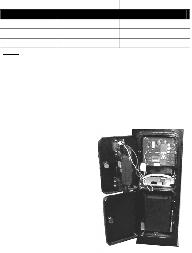
86
9.2. COIN MECH INSTALLATION AND CREDIT BOARD SET UP
9.2.1. INTRODUCTION
Game credits between the Coin Mechanism and the game board for this machine are controlled by a VTS
board. This electronic circuit allows the price of play to be set for a range of different countries. These
functions are set on Dual In Line (DIL) PCB mounted switches.
DIL-2 is used to set the currency (or coin ratio) and DIL-1 the price of play. Refer to the Tables on the
following pages for the correct settings for your environment.
The Klingon2 board pictured below is mounted on the VTS Bracket within the Coin Chute Tower.
The Klingon2 board is connected to the coin validator and lamps via a dedicated wiring harness depending
upon the coin validator used:
Wiring Harness Validator
LM1006 Coin Controls (15 way connector)
LM1007 Mars (13 way connector)
LM1008 Mechanical See note 2
N/A NRI See note 1
Notes
1. If NRI mechanisms are to be used, these should be ordered with the highest denomination coin on coin
path #1 and the lowest denomination on coin path #4. The VTS board should be then be set up for
either the UK or EURO settings. A minimum connecting lead length of 600mm is required.
2. Mechanical coin mechanisms may be connected in parallel allowing two identical mechanisms to be
fitted.
Illustration showing COIN TOWER, VTS PCB, COIN VALIDATOR and ASSOCIATED HARNESSES
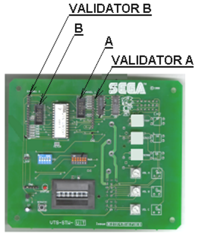
87
Illustration shows VTS PCB.
All COIN ASSIGNMENTS are carried out and processed by the VTS Board. This game uses a single SR3
Coin Validator (if supplied). This Validator will connect into port A as indicated by the illustration above.
All Credit settings are configured via the DIP switches also located on the VTS Board (please refer to later
on in this manual for the appropriate switch settings).
IMPORTANT – The CREDIT SETTINGS as displayed in the COIN ASSIGNEMNTS of the SYSTEM TEST
MODE in the LINDBERGH TEST MENU should always be set to 1 COIN = 1 CREDIT to maintain a correct
output from the VTS.
88
9.2.2. VTS CREDIT BOARD OPTION SETTINGS
Credit Board Mode Settings Switch 3
Country Setting Switch 3 Setting Coin Validator Programming C120/SR3 Only
SW1 SW2 SW3 SW4 SW5 SW6 COIN1 COIN2 COIN3 COIN4 COIN5 COIN6 COIN7 COIN8 COIN9 COIN10 COIN11 COIN12
UK Coin Controls
C220 Parallel
OFF OFF OFF OFF £1 50p new 20p 10p - 50p old - -
UK Coin Controls
C220 Binary
ON OFF OFF OFF £1 50p new 20p 10p - 50p old - £2
UK Coin Controls
C220 Binary
OFF ON OFF OFF £1 50p new 20p 10p - £2 - 50p
old
UK Coin Controls
SR3 Parallel
ON ON OFF OFF £1 50p new 20p 10p - £2 - 50p
old
- - - -
UK
Euro
Coin Controls
SR3 Parallel
OFF OFF ON OFF £2
€2
£1
€1
50p new
50¢
20p
20¢
10p
10¢
- - - 50p old - - -
UK Mars ME/MS
111 Parallel
ON OFF ON OFF £1 £2 20p 10p 50p new 50p old
UK NRI Parallel OFF ON ON OFF 10p 20p 50p £1 £2 -
Belgium Parallel ON ON ON OFF - 50BFr 20BFr 5BFr
Holland Parallel OFF OFF OFF ON - 5NLG 2.5NLG 1NLG
Austria SR3 Parallel ON OFF OFF ON 20Sch 10Sch 5Sch 1Sch
Spain Coin Controls
C220 Binary
OFF ON OFF ON 500Pta 200Pta 100Pta 50Pta 25Pta 200Pt
old
50Pta
old
25Pta
old
Spain SR3/NRI
Parallel
ON ON OFF ON 500Pta 200Pta 100Pta 50Pta 25Pta - - 200Pta - 50Pta
old
25Pta
old
-
Spain Coin Controls
C220 Parallel
OFF OFF ON ON 100Pta 50Pta
new
- 25Pta
new
- 50Pta
old
- 25Pta
old
Portugal
Euro
Parallel ON OFF ON ON 200Es
€1
100Es
50¢
50Es - - - - -
TBA OFF TBA Please Note
The credit board automatically sets the validator for parallel and binary
operation through an output on pin 8 of the 17 way pinstrip. For the feature
to work it is necessary for the validator interconnecting cable to include at
wire at this position
ON TBA
Channels OFF Direct Mode
ON 2 channel Mode
Note: These switch settings are under constant review and may change due to world currency updates.
• Set SW 1 according to the option settings found in the relevant Price of Play Settings Table on the following pages.
• For Germany (DM), France (Fr) & Switzerland (SFr), use the appropriate existing setting shown above (from another country) that matches the coin ratios programmed into your coin mech.
• Set SW 3 on the VTS /Excel board as shown in the table above corresponding to the country required.

89
9.2.3. PRICE OF PLAY SETTINGS UK
Price Bonus DIL Switch 1
Switch 1 Switch 2 Switch 3 Switch 4 Switch 5
1 10p No Bonus OFF OFF OFF OFF OFF
2 10p 6 = 50p ON OFF OFF OFF OFF
3 20p No Bonus OFF ON OFF OFF OFF
4 20p 3 = 50p 6 = £1 12 =£2 ON ON OFF OFF OFF
5 30p No Bonus OFF OFF ON OFF OFF
6 30p 1.66 = 50p 4 = £1 8 = £2 ON OFF ON OFF OFF
7 30p 2 = 50p 4 = £1 OFF ON ON OFF OFF
8 30p AMLD * 3 = £1 6 = £2 ON ON ON OFF OFF
9 40p No Bonus OFF OFF OFF ON OFF
10 40p 1.25 = 50p 3 = £1 6 = £2 ON OFF OFF ON OFF
11 50p No Bonus OFF ON OFF ON OFF
12 50p 3 = £1 6 = £2 ON ON OFF ON OFF
13 50p 2 = £1 5 = £2 OFF OFF ON ON OFF
14 60p No Bonus ON OFF ON ON OFF
15 60p 2 = £1 4 = £2 OFF ON ON ON OFF
16 80p No Bonus ON ON ON ON OFF
17 80p 1.25 = £1 2 = £1.50 2.5 = £2 OFF OFF OFF OFF ON
18 £1 No Bonus ON OFF OFF OFF ON
19 £1 3 = £2 OFF ON OFF OFF ON
20 £1 2 = £2 5 = £4 ON ON OFF OFF ON
21 £1.50 No Bonus OFF OFF ON OFF ON
22 £1.50 2 = £2 ON OFF ON OFF ON
23 £2 No Bonus OFF ON ON OFF ON
24 £2 3 = £5 ON ON ON OFF ON
25 £3 No Bonus OFF OFF OFF ON ON
26 £3 2 = £5 ON OFF OFF ON ON
27 £5 No Bonus OFF ON OFF ON ON
28 £5 3 = £10 ON ON OFF ON ON
29 £7.50 No Bonus OFF OFF ON ON ON
30 £7.50 2 = £10 ON OFF ON ON ON
31 £10 No Bonus OFF ON ON ON ON
32 Free Play ON ON ON ON ON

90
9.2.4. PRICE OF PLAY SETTINGS EURO
Price Bonus DIL Switch 1
Switch 1 Switch 2 Switch 3 Switch 4 Switch 5
1 10¢ No Bonus OFF OFF OFF OFF OFF
2 10¢ 6 = 50¢ ON OFF OFF OFF OFF
3 20¢ No Bonus OFF ON OFF OFF OFF
4 20¢ 3 = 50¢ 6 = €1 12 =€2 ON ON OFF OFF OFF
5 30¢ No Bonus OFF OFF ON OFF OFF
6 30¢ 1.66 = 50¢ 4 = €1 8 = €2 ON OFF ON OFF OFF
7 30¢ 2 = 50¢ 4 = €1 OFF ON ON OFF OFF
8 30¢ AMLD * 3 = €1 6 = €2 ON ON ON OFF OFF
9 40¢ No Bonus OFF OFF OFF ON OFF
10 40¢ 1.25 = 50¢ 3 = €1 6 = €2 ON OFF OFF ON OFF
11 50¢ No Bonus OFF ON OFF ON OFF
12 50¢ 3 = €1 6 = €2 ON ON OFF ON OFF
13 50¢ 2 = €1 5 = €2 OFF OFF ON ON OFF
14 60¢ No Bonus ON OFF ON ON OFF
15 60¢ 2 = €1 4 = €2 OFF ON ON ON OFF
16 80¢ No Bonus ON ON ON ON OFF
17 80¢ 1.25 = £1 2 = €1.50 2.5 = €2 OFF OFF OFF OFF ON
18 €1 No Bonus ON OFF OFF OFF ON
19 €1 3 = €2 OFF ON OFF OFF ON
20 €1 2 = €2 5 = €4 ON ON OFF OFF ON
21 €1.50 No Bonus OFF OFF ON OFF ON
22 €1.50 2 = €2 ON OFF ON OFF ON
23 €2 No Bonus OFF ON ON OFF ON
24 €2 3 = €5 ON ON ON OFF ON
25 €3 No Bonus OFF OFF OFF ON ON
26 €3 2 = €5 ON OFF OFF ON ON
27 €5 No Bonus OFF ON OFF ON ON
28 €5 3 = €10 ON ON OFF ON ON
29 €7.50 No Bonus OFF OFF ON ON ON
30 €7.50 2 = €10 ON OFF ON ON ON
31 €10 No Bonus OFF ON ON ON ON
32 Free Play ON ON ON ON ON
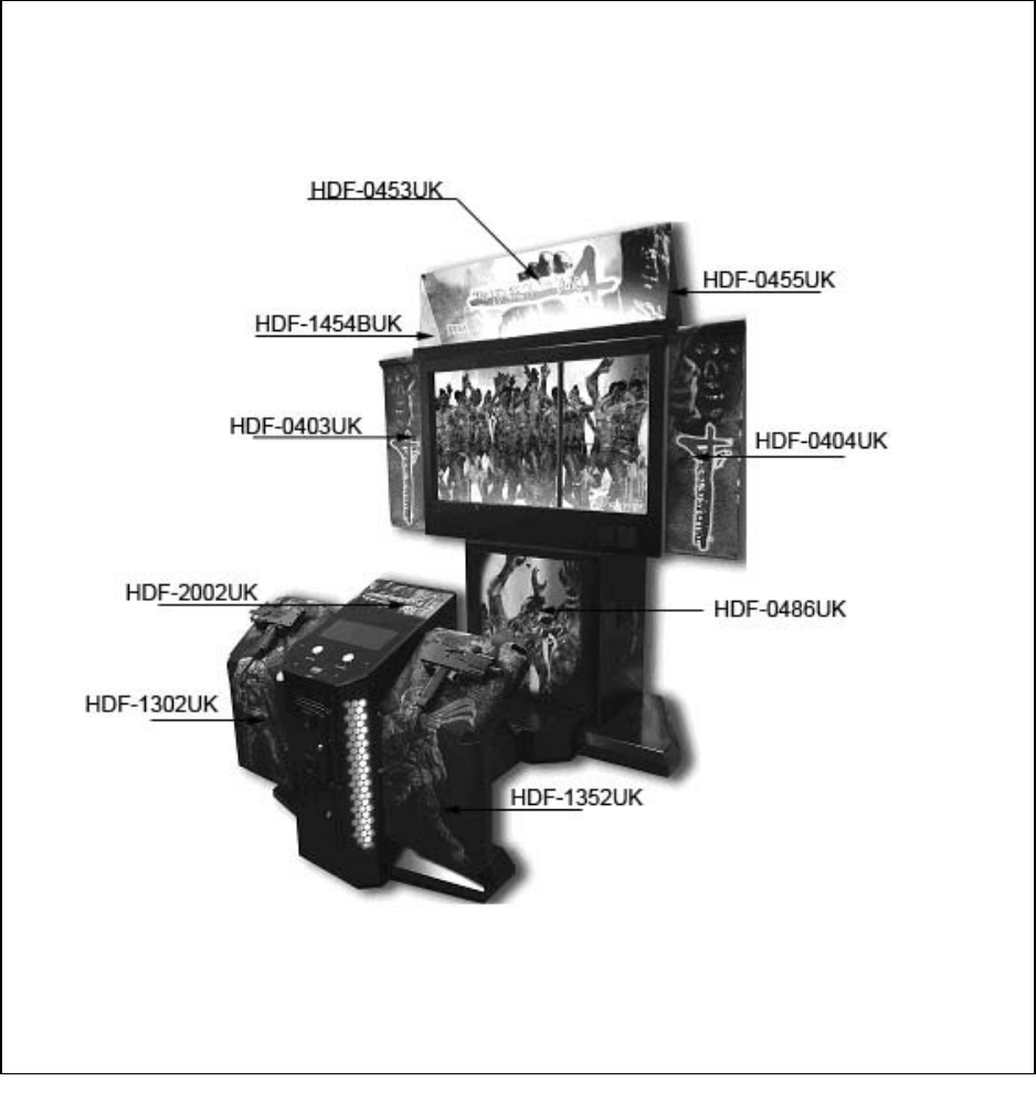
91
10. DESIGN RELATED PARTS
10.1. ARTWORK AND GRAPHICS

92
11. PARTS LIST
11.1. TOP ASSEMBLY (HDF-000-01UK)
No. PART NUMBER QTY DESCRIPTION COMPONENT REFERENCE
1 HDF-0400UK 1 ASSY DLP 52”
2 HDF-1000UK 1 ASSY CABINET DX
14 421-7987-HDF-D 1 STICKER ELEC SPEC HDF DX 52
15 421-7988-91UK 1 STICKER SERIAL NUMBER UK
16 LB1102 1 STICKER DANGEROUS VOLTAGE
19 421-7020UI 2 STICKER CAUTION FORK
30 LB1046 1 LABEL TESTED FOR SAFETY
31 LB1130 1 LABEL WEEE WHEELIE BIN
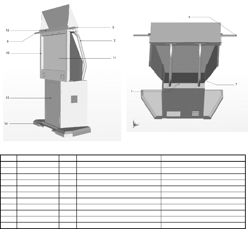
93
11.2. ASSY DLP 52 (HDF-0400UK)
No. PART NUMBER QTY DESCRIPTION COMPONENT REFERENCE
1 HDF-0401UK 1 BRKT REAR DLP
2 HDF-0402UK 2 REAR SUPPORT LEG
5 HDF-0405UK 1 ASSY BANNER R
6 HDF-0406UK 1 ASSY BANNER L
7 HDF-0407UK 1 PLATE REAR DLP
8 HDF-0408UK 2 END CAP BANNER
10 HDF-0430UK 1 ASSY MASK
11 200-6052-LG 1 ASSY DLP 52 LG 52SZ8R
12 HDF-0450UK 1 ASSY BILLBOARD DX 52
13 HDF-0480UK 1 ASSY DLP LWR BASE
14 HDF-0670UK 1 ASSY SUB BASE
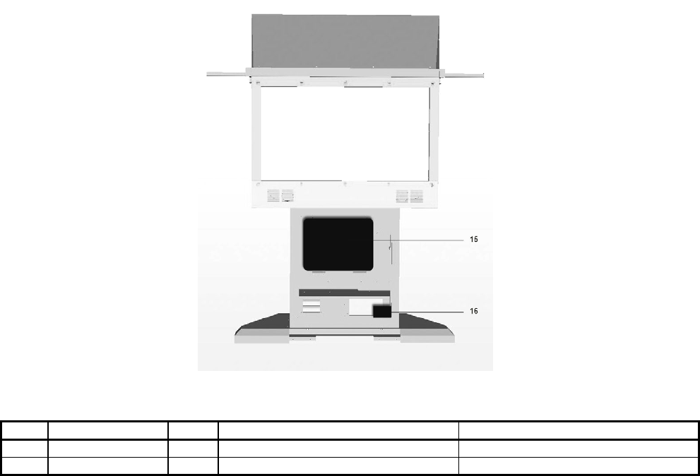
94
ASSY DLP BASE continued……………..
No. PART NUMBER QTY DESCRIPTION COMPONENT REFERENCE
15 HDF-4000UK 1 ASSY MAIN BOARD
16 HDF-4200UK 1 ASSY XFMR

95
11.3. ASSY MASK 52 (HDF-0431UK)
No. PART NUMBER QTY DESCRIPTION COMPONENT REFERENCE
1 HDF-0431UK 1 MONITOR MASK 52” HDF
6 JPT-1082 10 IR COVER
7 838-13145-02 10 LED BD GUN SENSE HOD
301 HDF-60009UK 1 WH MASK EXT 1
302 HDF-60010UK 2 WH MASK EXT 2
303 HDF-60011UK 7 WH MASK LINK

96
11.4. ASSY BILLBOARD DX 52” (HDF-0450UK)
No. PART NUMBER QTY DESCRIPTION COMPONENT REFERENCE
1 HDF-0451UK 1 BILLBOARD BOX 52 HDF
2 HDF-0452UK 1 BRKT LIGHT BILLBOARD PLATE
3 HDF-0453UK 1 BILLBOARD PLATE
4 HDF-0454UK 1 SUPPORT L
5 HDF-0455UK 1 SUPPORT R
6 HDF-0456UK 1 LIGHT COVER
7 HDF-0457UK 3 BRKT FL TUBE HOLDER NOT SHOWN
101 390-7001-03UK 1 FL TUBE LSTR30W NOT SHOWN
301 HDF-61010UK 1 WH BILLBOARD NOT SHOWN
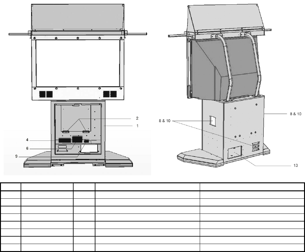
97
11.5. ASSY DLP LOWER BASE (HDF-0480UK)
No. PART NUMBER QTY DESCRIPTION COMPONENT REFERENCE
1 HDF-0481UK 1 CABINET ASSY DLP LWR BOX
2 HDF-0482UK 2 BRKT MAIN BOARD
4 610-0719-01 1 DVD DRIVE UNIT USB
6 400-5457-91 1 SW REGU ATX/JVS
8 253-5460-01 3 AIR VENT BLACK
9 400-5421-05012 1 SW REGU LCA50S-12
10 HOD-1530UK 2 ASSY FAN UNIT UK
13 HDF-6006UK 1 ASSY AC UNIT
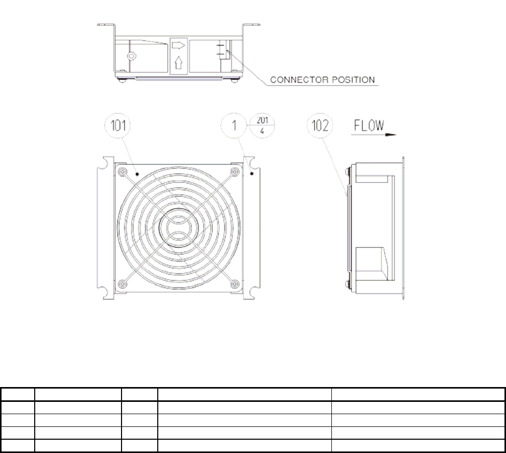
98
11.6. ASSY FAN UNIT UK (HOD-1530UK)
No. PART NUMBER QTY DESCRIPTION COMPONENT REFERENCE
1 105-5340-01 2 FAN BRKT LONG
101 260-0011-02 1 FAN AC100V 50/50HZ
102 FN1012 1 FAN GUARD METAL 120MM
201 000-P00312-W 4 M3X12 MSCR PAN W/FS PAS
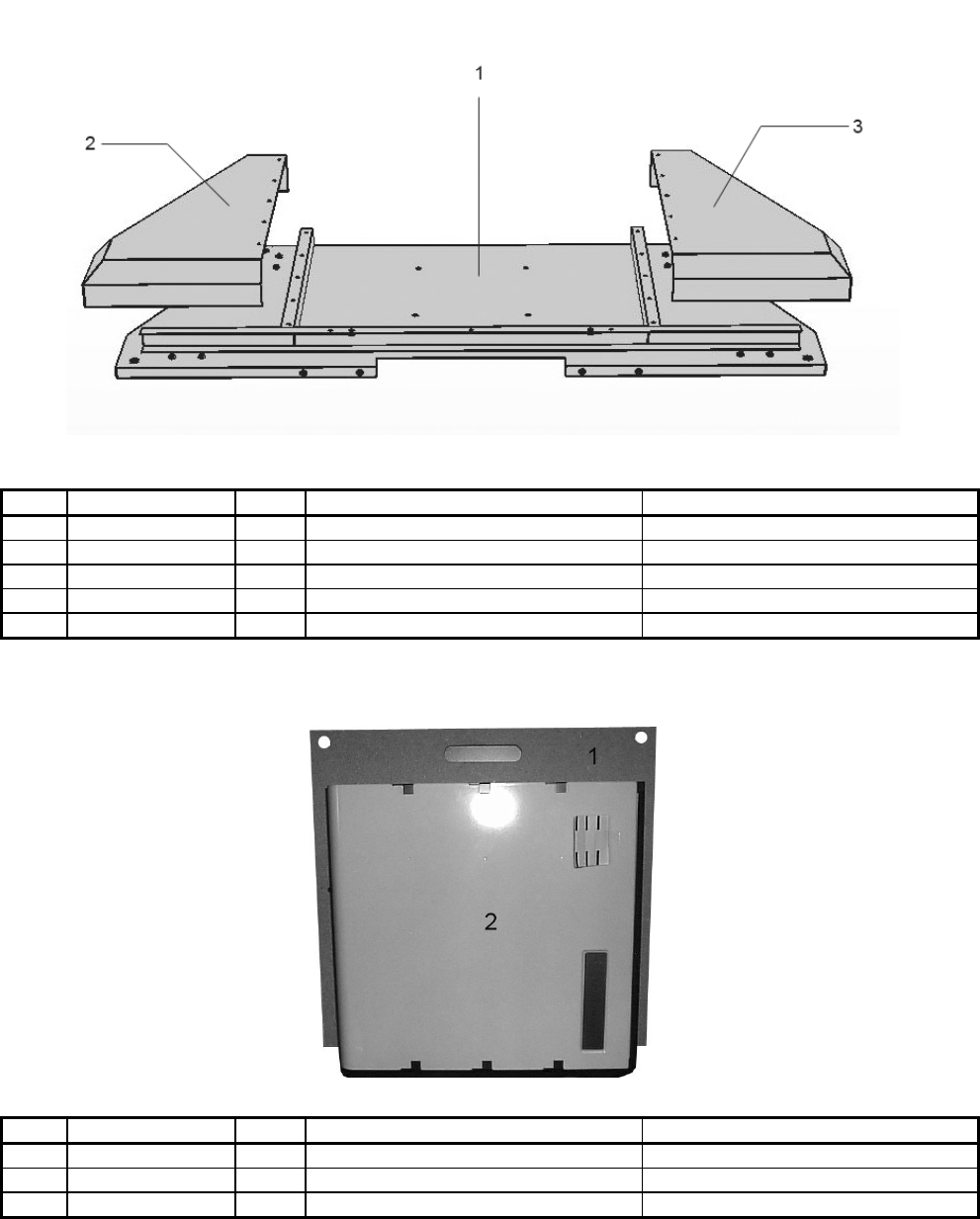
99
11.7. ASSY SU DLP BASE (HDF-0670UK)
No. PART NUMBER QTY DESCRIPTION COMPONENT REFERENCE
1 HDF-0671UK 1 DLP BASE
2 HDF-0672UK 1 SHOE L
3 HDF-0673UK 1 SHOE R
101 601-9377 4 CASTOR FAI-75 NOT SHOWN
102 601-5699UK-01 4 LEG ADJ M16X130 1L/NUT NOT SHOWN
11.8. ASSY SUB DLP BASE (HDF-0670UK)
No. PART NUMBER QTY DESCRIPTION COMPONENT REFERENCE
1 HDF-4001UK 1 MAIN BOARD
2 844-002D-15 1 ASSY CASE LBG L 1GB HDF
301 HDF-61006UK 1 WH PSU LINDBERGH NOT SHOWN

100
11.9. ASSY CABINET DX (HDF-1000UK)
No. PART NUMBER QTY DESCRIPTION COMPONENT REFERENCE
1 HDF-1100UK 1 ASSY SUB CABINET DX
2 HDF-1010UK 1 ASSY LIGHT COVER L
3 HDF-1020UK 1 ASSY LIGHT COVER R
4 HDF-1300UK 1 ASSY GUN HOLDER L
5 HDF-1350UK 1 ASSY GUN HOLDER R
6 HDF-2000UK 1 ASSY CONTROL PANEL
11.10. ASSY SUB CABINET DX (HDF-1100UK)
No. PART NUMBER QTY DESCRIPTION COMPONENT REFERENCE
1 HDF-1101-AUK 1 CABINET DX BLANK
2 HDF-1108UK 1 CASTOR BKT
3 HDF-1109UK 1 FOOT BASE
101 601-5699X 2 LEG ADJUSTER BOLT M16X75
102 601-6056-01 4 CASTOR 50 PH
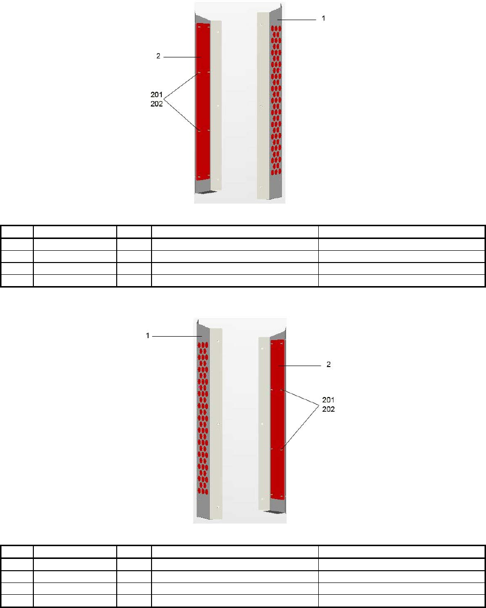
101
11.11. ASSY LIGHT COVER R (HDF-1020UK)
No. PART NUMBER QTY DESCRIPTION COMPONENT REFERENCE
1 HDF-1021UK 1 LIGHT COVER R
2 HDF-1012UK 1 LIGHT COVER FRONT
201 060-F00400 8 M4 WSHR FORM A FLT PAS
202 050-U00400 8 M4 NUT NYLOCK PAS
11.12. ASSY LIGHT COVER L (HDF-1010UK)
No. PART NUMBER QTY DESCRIPTION COMPONENT REFERENCE
1 HDF-1011UK 1 LIGHT COVER L
2 HDF-1012UK 1 LIGHT COVER FRONT
201 060-F00400 8 M4 WSHR FORM A FLT PAS
202 050-U00400 8 M4 NUT NYLOCK PAS
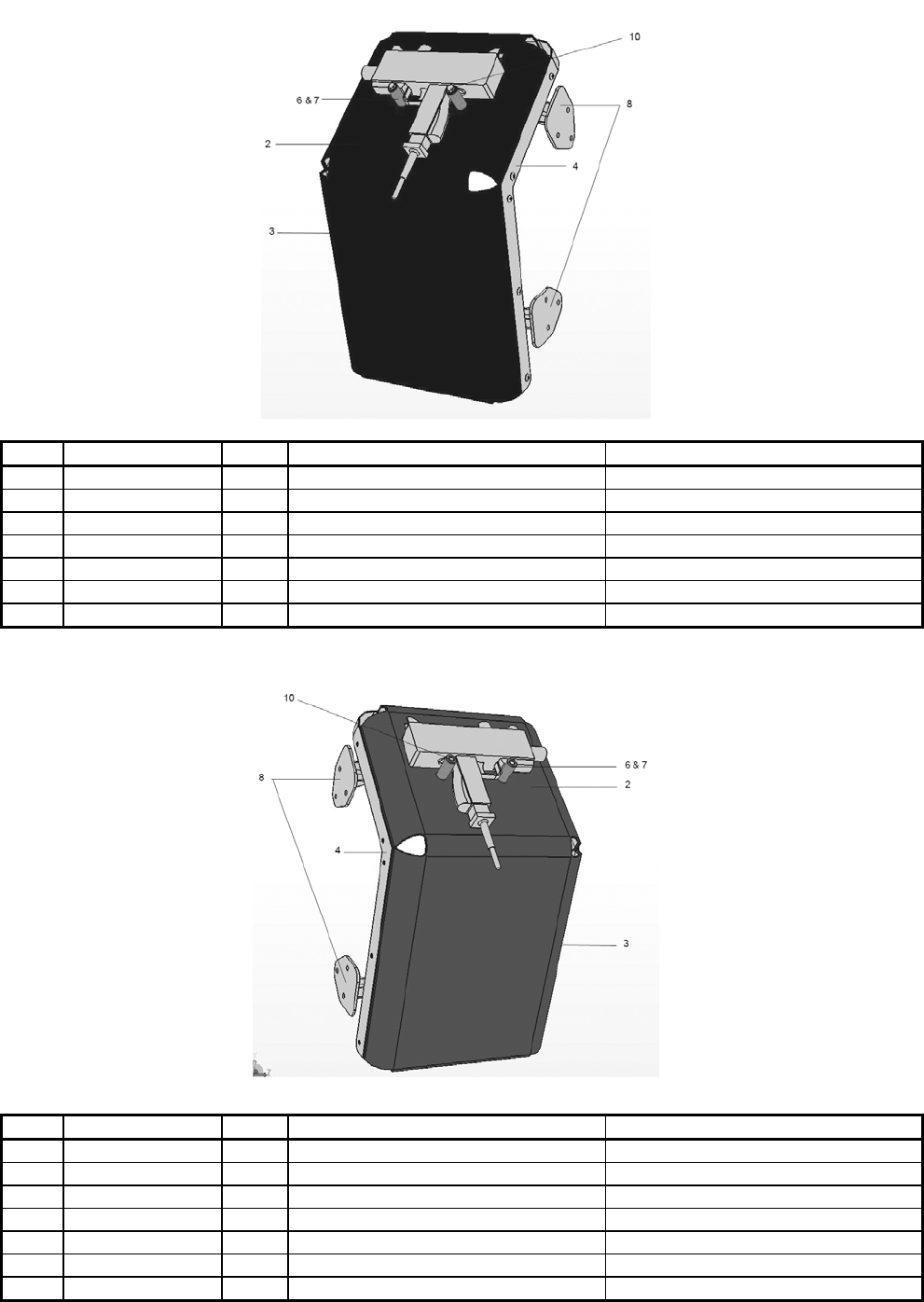
102
11.13. ASSY GUN HOLDER L (HDF-1300UK)
No. PART NUMBER QTY DESCRIPTION COMPONENT REFERENCE
2 HDF-1302UK 1 MAT HOLDER L
3 HDF-1303UK 1 STRAP HOLDER L
4 HDF-1304UK 1 STRAP HOLDER R
6 SPY-5104UK 2 GUN CUSHION A
7 SPY-5110UK 2 CUSHION BAR
8 HDF-1306UK 2 HOLDER SUPPORT
10 SDW-0001UK 2 BLIND CAP
11.14. ASSY GUN HOLDER R (HDF-1350UK)
No. PART NUMBER QTY DESCRIPTION COMPONENT REFERENCE
2 HDF-1352UK 1 MAT HOLDER R
3 HDF-1303UK 1 STRAP HOLDER L
4 HDF-1304UK 1 STRAP HOLDER R
6 SPY-5104UK 2 GUN CUSHION A
7 SPY-5110UK 2 CUSHION BAR
8 HDF-1306UK 2 HOLDER SUPPORT
10 SDW-0001UK 2 BLIND CAP
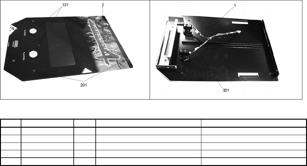
103
11.15. ASSY CONTROL PANEL (HDF-2000UK)
No. PART NUMBER QTY DESCRIPTION COMPONENT REFERENCE
1 HDF-2001UK 1 CONTROL PANEL BASE
2 HDF-2002UK 1 CONTROL PANEL PLATE
101 509-6101 2 SW PB OBSA-45UM-Y-1FLED-5V
201 008-T00412-0B 4 M4X12 TMP PRF MSCR BLK
301 HDF-60034UK 1 HARNESS CONT PAN

104
12. APPENDIX A - ELECTRICAL SCHEMATIC
12.1. WIRE COLOURS
THE WIRE COLOUR CODE IS AS FOLLOWS:
A PINK
B SKY BLUE
C BROWN
D PURPLE
E LIGHT GREEN
Wires other than those of any of the colours listed above will be displayed by 2 alphanumeric characters:
1 RED
2 BLUE
3 YELLOW
4 GREEN
5 WHITE
7 ORANGE
8 BLACK
9 GREY
If the right hand side numeral of the code is 0, then the wire will be of a single colour shown by the left hand
side numeral (see the list above).
Note 1: If the right hand side alphanumeric is not 0, that particular wire has a spiral colour code. The left
hand side character shows the base colour and the right hand side one, the spiral colour.
[Example] 51------------- WHITE/RED = WHITE wire with RED stripes
Note 2: The character following the wire colour code indicates the size of the wire.
K: AWG18, UL1015
L: AWG20, UL1007
None AWG22, UL1007
105
12.2. ELECTRICAL SCHEMATIC
The following page contains the electrical schematic for this machine.

© SEGA 2005
SEGA AMUSEMENTS EUROPE LTD.
Suite 3a.
Oak House
12-22 West street
Epsom
Surrey
United Kingdom
KT18 7RG
Telephone: +44(0) 1372 731820
Fax: +44(0) 1372 731849
