Arcade Lindbergh Red Manual User
2013-11-20
User Manual: Arcade Lindbergh Red Manual
Open the PDF directly: View PDF ![]() .
.
Page Count: 32
SERVICE MANUAL
• Before using this product, read this manual carefully to understand the
contents herein stated.
• After reading this manual, be sure to keep it near the product or in a
convenient place for easy reference when necessary.
IMPORTANT
© SEGA
420-7032-01UK
1ST PRINTING
Suite 3a, Oaks House, 12/22 West Street, Epsom, Surrey.
KT18 7RG. United Kingdom.
Tel: +441372 731820. Fax: +441372 731849
SEGA AMUSEMENTS EUROPE LIMITED
TABLE OF CONTENTS
i
TABLE OF CONTENTS
E0-0703 420-7032-01
BEFORE USING THE PRODUCT, BE SURE TO READ THE FOLLOWING:
TABLE OF CONTENTS
INTRODUCTION
1HANDLING PRECAUTIONS
LINDBERGH RED SPECIFICATIONS
2-1 CABINET
2-2 PARTS DETAILS
LINDBERGH RED COMPONENTS
SYSTEM TEST MODE
ERROR CODES DISPLAY
REPLACING THE BUTTON BATTERIES
2
3
4
5
6
∙∙∙∙∙∙∙∙∙∙∙∙∙∙∙∙∙∙∙∙∙∙∙∙∙∙∙∙∙∙∙∙∙∙∙∙∙∙∙∙∙∙∙∙∙∙∙∙∙∙∙∙∙∙∙∙∙∙∙∙∙∙∙∙∙∙∙∙∙∙∙∙∙∙∙∙∙∙∙∙∙∙∙∙∙∙∙∙∙∙∙∙∙∙∙∙1
∙∙∙∙∙∙∙∙∙∙∙∙∙∙∙∙∙∙∙∙∙∙∙∙∙∙∙∙∙∙∙∙∙∙∙∙∙∙∙∙∙∙∙∙∙∙∙∙∙∙∙∙∙∙∙∙∙∙∙∙∙∙∙∙∙∙∙∙∙∙∙∙3
∙∙∙∙∙∙∙∙∙∙∙∙∙∙∙∙∙∙∙∙∙∙∙∙∙∙∙∙∙∙∙∙∙∙∙∙∙∙∙∙∙∙∙∙∙∙∙∙∙∙∙∙∙∙∙∙∙4
∙∙∙∙∙∙∙∙∙∙∙∙∙∙∙∙∙∙∙∙∙∙∙∙∙∙∙∙∙∙∙∙∙∙∙∙∙∙∙∙∙∙∙∙∙∙∙∙∙∙∙∙∙∙∙∙∙∙∙∙∙∙∙∙∙∙∙∙∙∙∙∙∙∙∙∙∙∙∙∙∙∙∙∙∙∙∙∙∙∙∙∙∙∙∙∙∙∙∙∙∙∙∙∙∙∙∙∙∙∙∙∙∙∙∙4
∙∙∙∙∙∙∙∙∙∙∙∙∙∙∙∙∙∙∙∙∙∙∙∙∙∙∙∙∙∙∙∙∙∙∙∙∙∙∙∙∙∙∙∙∙∙∙∙∙∙∙∙∙∙∙∙∙∙∙∙∙∙∙∙∙∙∙∙∙∙∙∙∙∙∙∙∙∙∙∙∙∙∙∙∙∙∙∙∙∙∙∙∙∙∙∙∙∙∙∙∙∙∙5
∙∙∙∙∙∙∙∙∙∙∙∙∙∙∙∙∙∙∙∙∙∙∙∙∙∙∙∙∙∙∙∙∙∙∙∙∙∙∙∙∙∙∙∙∙∙∙∙∙∙∙∙∙∙∙∙∙∙∙∙∙∙∙9
∙∙∙∙∙∙∙∙∙∙∙∙∙∙∙∙∙∙∙∙∙∙∙∙∙∙∙∙∙∙∙∙∙∙∙∙∙∙∙∙∙∙∙∙∙∙∙∙∙∙∙∙∙∙∙∙∙∙∙∙∙∙∙∙∙∙∙∙∙∙∙∙∙∙∙∙∙∙∙∙10
∙∙∙∙∙∙∙∙∙∙∙∙∙∙∙∙∙∙∙∙∙∙∙∙∙∙∙∙∙∙∙∙∙∙∙∙∙∙∙∙∙∙∙∙∙∙∙∙∙∙∙∙∙∙∙∙∙∙∙∙∙∙∙∙∙∙∙∙∙∙∙∙∙24
∙∙∙∙∙∙∙∙∙∙∙∙∙∙∙∙∙∙∙∙∙∙∙∙∙∙∙∙∙∙∙∙∙∙∙∙∙∙∙∙∙∙∙∙∙∙∙∙∙∙28
ii
TABLE OF CONTENTS
This product uses GPL/LGPL software.
This means that customers who purchase this product can freely obtain, alter and pass-on the source code for this
software (hereafter referred to as “the source code”).
Downloaded this software is an indication of the customer’s agreement to the GPL/LGPL contract of use and thus
the download and all subsequent use of the source code is the full responsibility of the customer.
Furthermore this source code and the download service are provided totally as-is, with no guarantees of
effectiveness, completeness, usefulness or reliability, and our company offers no support concerning this source
code.
GPL/LGPL Contract Site
URL: http: //www.fsf.org/licenses/gpl.html
URL: http: //www.fsf.org/licenses/lgpl.html
Customers using this product who wish to obtain this source code should enter the following password on the
website below to download it.
URL: http: //amproduct-softlicense.sega.jp/
ID: amsoftwebdl
Password: segaamhd1
(1) Use of GPL/LGPL software
At the web site given above, the Company gives notice of information on licensed software other than GPL/LGPL
based on stipulations by the copyright holders. Please note, however, that the Company cannot answer inquiries
pertaining to this software.
(2) Licensed Software Other Than GPL/LGPL
1
INTRODUCTION
Indicates important information that, if ignored, will result in the mishandling of the
product and cause faulty operation and damage to the product.
This manual is intended to provide detailed descriptions together with all the necessary information covering the
general operation of electronic assemblies, electro-mechanicals, servicing control, spare parts, etc. for the product,
"LINDBERGH RED."
This manual is intended for the owners, personnel and managers in charge of operation of the product. Operate the
product after carefully reading and sufciently understanding the instructions.
In the unlikely event that the product does not function correctly, DO NOT allow anyone other than a technician to
touch the internal system. Turn off power to the machine, making sure to unplug the electrical cord from the outlet,
and contact the ofce listed in the manuals for each game or the point-of-purchase for this product.
Use of this product is unlikely to cause physical injuries or damages to property. However, points that require special
attention are indicated by thick underlining, the word "IMPORTANT" and the symbol below.
SEGA AMUSEMENTS EUROPE, LTD.
Suite 3a, Oaks House 12-22, West Street, Epsom, Surrey, KT18 7RG, United Kingdom
Telephone: +44 (0) 1372 731820 Facsimile: +44 (0) 1372 731849
e-mail: mailbox@sega.co.uk http://www.sega-amusements.co.uk
INTRODUCTION
2
INTRODUCTION
Denition of 'Site Maintenance Personnel or Other Qualied Individuals'
Procedures not described in this manual or marked as 'to be carried out by site
maintenance personnel or other qualified professionals' should not be carried
out by personnel without the necessary skill or technology. Work carried out by
unqualied persons may cause serious accidents, including electrocution.
Parts replacement, maintenance inspections and troubleshooting should be carried out by site maintenance personnel
or other qualied professionals. This manual includes directions that potentially dangerous procedures should only
be carried out by professionals with the appropriate specialized knowledge.
The 'site maintenance personnel or other qualied professionals' mentioned in this manual are dened as follows:
Site maintenance personnel:
Persons with experience in maintaining amusement equipment, vending machines, etc., working under the
supervision of the owner/operator of this product to maintain machines within amusement facilities or similar
premises by carrying out everyday procedures such as assembly, maintenance inspections, and replacement of units/
expendable parts.
Activities to be carried out by site maintenance personnel:
Amusement equipment/vending machine assembly, maintenance inspection and replacement of units/expendable
parts.
Other qualied professionals:
Persons employed by amusement equipment manufacturers, involved in design, production, testing or maintenance
of amusement equipment. Should have graduated from technical school or hold similar qualications in electrician/
electronics/mechanical engineering.
Activities to be carried out by other qualied professionals:
Amusement equipment/vending machine assembly, repair/adjustment of electrical/electronic/mechanical parts.
HANDLING PRECAUTIONS
1
3
• To prevent electric shock or IC Board malfunctioning, be sure to turn off the
power for the cabinet when installing or removing the IC Board.
• Extraneous matter such as dust on the IC Board can cause the IC Board to
generate heat and result in a re due to short circuit, etc. Ensure the IC Board
surfaces are always kept clean.
• Keep the IC board well cooled. The LINDBERGH RED board case is provided with
ventilating fans. Do not block the air outlets of these fans. Also do not place
anything closely to the LINDBERGH RED board case. Failure to observe these
instructions may cause an overheating and re.
• Use the LINDBERGH RED board with the SEGA specied cabinet and the power
cable. Using it with the non-specied cabinet or the power cable may cause an
overheating and re.
HANDLING PRECAUTIONS1
• Be sure to connect the IC Board and connectors completely. Insufcient
insertion can damage IC Board, etc.
• For the IC Board circuit inspection, only the use of Logic Tester is permitted. The
use of ordinary testers is not permitted as these can damage the IC Board.
• Do not subject the IC Board to static electricity when installing the IC Board in
the cabinet or when connecting wire harness connectors to the IC Board.
• When soldering buttons, etc. to the wire harnesses, be sure to remove the wire
harnesses from the IC Board so as not to subject the IC Board to heat.
• Using LINDBERGH RED without the Shield Case can cause electric wave trouble.
Be sure to use LINDBERGH RED together with the accessory Shield Case.
• Some parts are the ones designed and manufactured not specically for
this game machine. The manufacturers may discontinue, or change the
specications of, such general-purpose parts. If this is the case, Sega cannot
repair or replace a failed game machine whether or not a warranty period has
expired.
2
LINDBERGH SPECIFICATIONS
4
LINDBERGH RED SPECIFICATIONS2
2-1 CABINET
- Use the LINDBERGH RED board with the SEGA specied cabinet.
- When using the NAOMI CABINET, NET CITY, NEW NET CITY or BLAST CITY cabinets, you must acquire
the correct kits, including the special power supply, and modify the cabinet correctly for LINDBERGH RED use.
Cabinet Required Kit
NAOMI CABINET NAOMI NET CITY series power supply modication kit (XKT-1516-EX1)
FAN motor kit (XKT-0856)
NET CITY NAOMI NET CITY series power supply modication kit (XKT-1516-EX1)
NEW NET CITY NAOMI NET CITY series power supply modication kit (XKT-1516-EX1)
BLAST CITY BLAST CITY series power supply modication kit (XKT-1516-01-EX1) <Others>
BLAST CITY series power supply modication kit (XKT-1516-01-EX2) <Taiwan>
NOTE: The contents herein described are subject to change without notice.
LINDBERGH SPECIFICATIONS
2
5
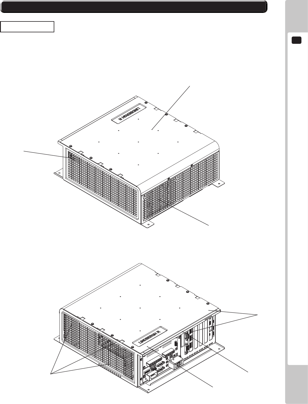
(1) Shield case
(2) Intake vent (Do not block or cover.)
(3) Exhaust vent (Do not block or cover.)
(4) Board number
(5) Board serial number (1)
(3)
(2)
(2)
(5)
(4)
(2)
2-2 PARTS DETAILS
BOARD CASE
2
LINDBERGH SPECIFICATIONS
6
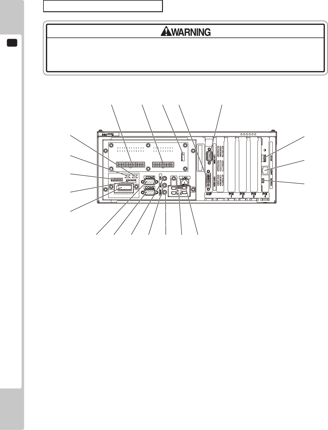
(1) Power connector 1
(2) Power connector 2
(3) DVD Drive power connector
(4) Video output 0
(5) Video output 1
(6) JVS I/O
(7) LAN port 2
(8) Serial port 3
(9) LAN port 1
(10) USB Port 1 - 4 (USB Mini A)
(11) Front lineout
(12) Rear lineout
(13) Centre/Woofer lineout
(14) Serial port 2 (RS232C)
(15) Serial port 1 (RS232C)
(16) Key chip socket
(17) Serial port 2 (MIDI) …used instead of (14) Serial port 2 (RS232C)
(18) DIP SW (Dip switches)
(19) Service button
(20) Test button
(5)(4)(3)(2)(1)
(15) (14) (13) (12) (11) (10) (9)
(6)
(7)
(8)
(20)
(19)
(18)
(17)
(16)
CONNECTORS AND SWITCHES
Do not connect components to (6) JVS I/O or (8) Serial port 3 that are not
designated by SEGA. Connecting unspecified components could cause an
accident such as an electric shock or re.
LINDBERGH SPECIFICATIONS
2
7
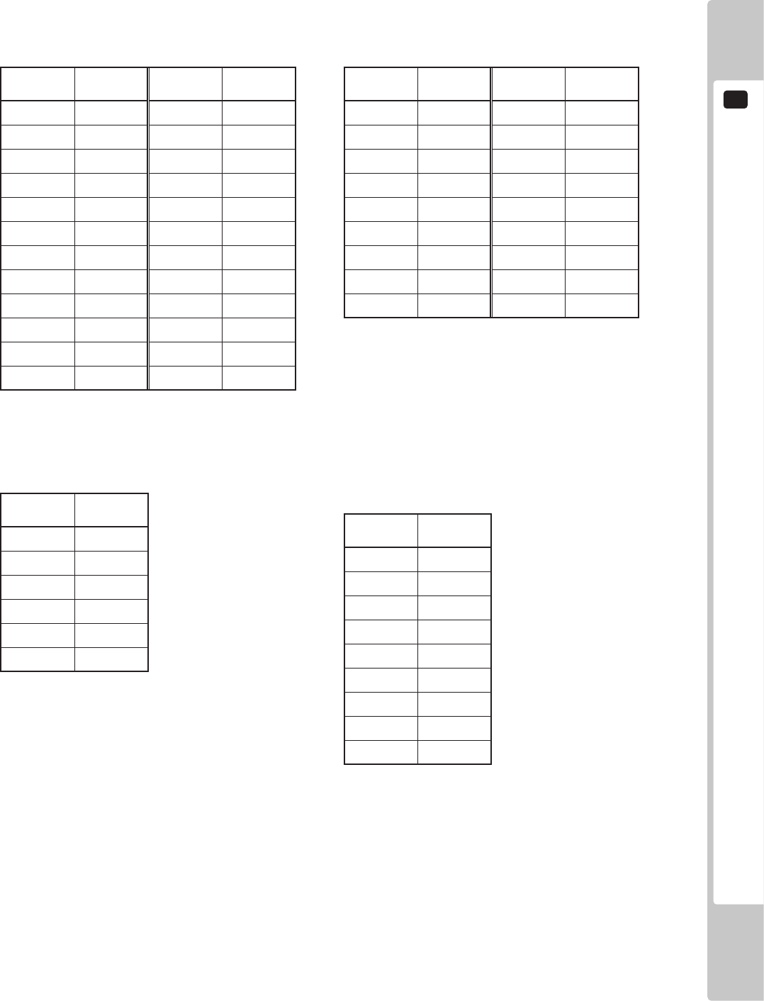
Terminal
No.
Signal
Name
Terminal
No.
Signal
Name
1 +3.3V 13 +3.3V
2 +3.3V 14 N.C
3 GND 15 GND
4+5V 16 PS_ON#
5GND 17 GND
6 +5V 18 GND
7 GND 19 GND
8 PWR_ON 20 NC
9+5SB 21 +5V
10 +12V 22 +5V
11 +12V 23 +5V
12 +3.3V 24 GND
(1) Power Connector 1
Terminal
No.
Signal
Name
Terminal
No.
Signal
Name
1 +12V 10 GND
2 +12V 11 GND
3+5V 12 GND
4 +12V 13 GND
5 +5V 14 GND
6+12V 15 GND
7+5V 16 GND
8 +12V 17 GND
9
3.3VRS(SENCE)
18 +3.3V
(2) Power Connector 2
Terminal
No.
Signal
Name
1 +12V
2 +12V
3+5V
4+5V
5GND
6GND
(3) DVD DRIVE Power Connector
Terminal
No.
Signal
Name
1 DCD
2RXD
3TXD
4 DTR
5GND
6DSR
7 RTS
8 CTS
9 RI
(14) Serial port 2 (RS232C)
(15) Serial port 1 (RS232C)
2
LINDBERGH SPECIFICATIONS
8
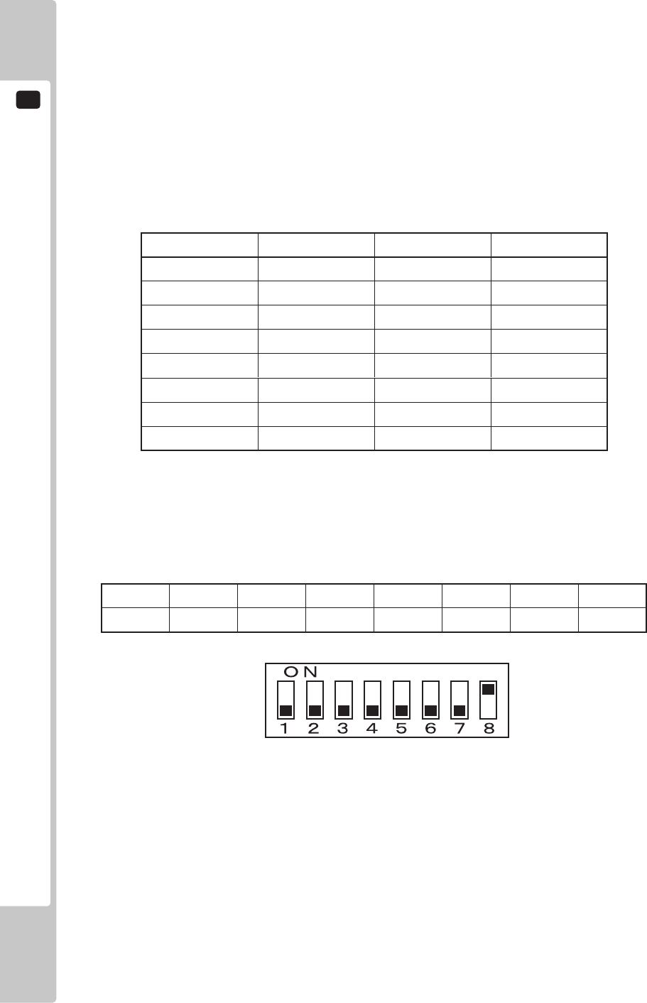
(18) DIP SW
No. 1, No. 2: Use differs depending on game software. Set according to the service manual provided with the game
software itself.
No. 3: Changes the facing of the monitor. Use differs depending on game software. Set according to the service
manual provided with the game software itself. If no specic directions are given set to horizontal display
(OFF).
OFF: Horizontal display
ON: Vertical display
No. 4, No. 5 and No. 6: Set the resolution of the video output.
Resolution No. 4 No. 5 No. 6
640
x
480 OFF OFF OFF
800
x
600 OFF OFF ON
1024
x
768 OFF ON OFF
1280
x
1024 OFF ON ON
800
x
480 ON OFF OFF
1024
x
600 ON OFF ON
1280
x
768 ON ON OFF
1360
x
768 ON ON ON
No. 7, No. 8: Use differs depending on game software. Set according to the service manual provided with the game
software itself.
The factory settings when a game board (LINDBERGH RED) is purchased as a stand-alone unit.
No. 1 No. 2 No. 3 No. 4 No. 5 No. 6 No. 7 No. 8
OFF OFF OFF OFF OFF OFF OFF ON
LINDBERGH COMPONENTS
3
9
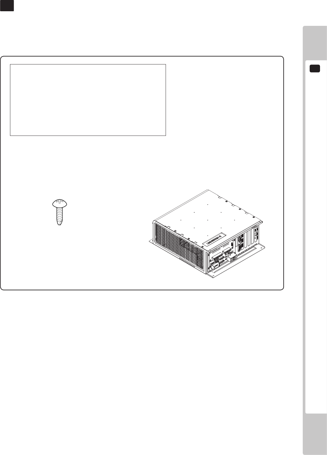
3 TABLE 01 ACCESSORIES
DESCRIPTION SERVICE MANUAL
Part No. (Qty) 420-7032-01 (1)
Notes This manual
Figures
Parts not labeled with part numbers are as yet unregistered or
cannot be registered. Be sure to handle all parts with care, as
some parts are not available for purchase separately.
LINDBERGH RED COMPONENTS3
Conrm that the accessories listed in the table below are present when setting up the product.
TAPPING SCREW
011-P00412 (4)
Used for securing the LINDBERGH
LINDBERGH RED BOARD
845-0001D-01 (1): USA
845-0001D-02 (1): OTHERS
4
SYSTEM TEST MODE
10
SYSTEM TEST MENU
SYSTEM INFORMATION
STORAGE INFORMATION
JVS TEST
MONITOR TEST
SPEAKER TEST
COIN ASSIGNMENTS
CLOCK SETTING
NETWORK SETTING
GAME TEST MODE
-> EXIT
SELECT WITH SERVICE AND PRESS TEST
SYSTEM TEST MODE4
1
Press the TEST Button after powering on the unit to display the following SYSTEM TEST MENU.
System Test Mode can be used to check the information or the operation of the LINDBERGH RED board, adjust
Monitor color, and perform coin/credit settings.
a
b
c
d
e
f
g
h
i
The details of changes to Test Mode settings are saved when you exit from Test
Mode by selecting EXIT from the SYSTEM TEST MENU. Be careful because if the
power is turned off before that point, changes to the settings will be lost.
2
Use the SERVICE Button to move the cursor to the desired test item. Press the TEST Button to enter the
selected item. After selecting an item, read the explanations below regarding operation.
3
Press the TEST Button when GAME TEST MODE is selected to change to the Test Menu specic to the
game.
4
After the test is complete, move the cursor to EXIT and press the TEST Button to return to the Game
Advertisement screen.
SYSTEM TEST MENU
SYSTEM TEST MODE
4
11
The SYSTEM INFORMATION screen displays system information.
a. SYSTEM INFORMATION
The following information is displayed on this screen.
• MOTHER BOARD
- SERIAL NO.: The serial number of the game board.
- KERNEL VERSION: The system’s OS version.
- BOOT VERSION: The boot program version.
- REGION: The region setting.
- MODEL TYPE: The model type.
- MEMORY SIZE: The onboard memory size.
- CPU MODEL: The CPU model.
• STORAGE DEVICE
- STORAGE SIZE: The total capacity of the program installer device.
• BASE BOARD
- SERIAL NO.: The serial number.
- FIRM VERSION: The rmware version.
• GRAPHIC BOARD
- DEVICE ID: The graphic board’s ID.
- BIOS VERSION: The VBIOS version.
Press the TEST Button to return to the System Test Menu screen.
SYSTEM INFORMATION
MOTHER BOARD
SERIAL NO. AAH*-*************
KERNEL VERSION *.*.**_*****
BOOT VERSION *.**(BUILD ****)
REGION **
MODEL TYPE *
MEMORY SIZE *******
CPU MODEL *.**
STORAGE DEVICE
STORAGE SIZE ***** MB
BASE BOARD
SERIAL NO. A80*-*************
FIRM VERSION *.**
GRAPHIC BOARD
DEVICE ID ******
BIOS VERSION **.**.**.**.**
PRESS TEST TO EXIT
4
SYSTEM TEST MODE
12
STORAGE INFORMATION
*******
GAME ID ****
PROGRAM TYPE CLIENT
0) ****:*.** yyyy/mm/dd
UNINSTALL
-> EXIT
SELECT WITH SERVICE AND PRESS TEST
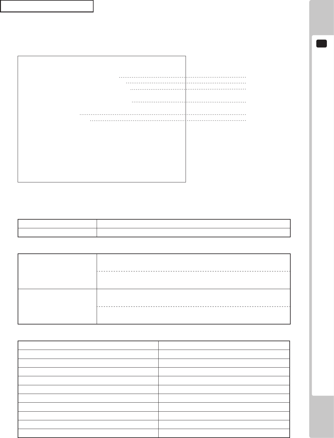
The STORAGE INFORMATION screen displays information on the game contained within the program installer
device. This screen is also used when uninstalling the game contained within the program installer device.
Until preparations to launch the game are complete, a “now checking” screen will be displayed and uninstall
cannot be performed. If the program installer device does not contain any game data, the game information will be
displayed in grey and uninstall cannot be performed.
NOTE: If an uninstall is performed, an install will then have to performed before the game board can be used again.
Do not needless perform an uninstall.
b. STORAGE INFORMATION
The following information is displayed on this screen.
b - 1. GAME TITLE
b - 2. GAME ID
b - 3. PROGRAM TYPE
b - 4. INSTALLED IMAGE LIST
- IMAGE NUMBER
- GAME ID
- VERSION
- DATE OF RELEASE
b - 5. UNINSTALL
When preparations to launch the game are complete, it is possible to uninstall the game stored in the program
install device. Select UNINSTALL and then select “YES” to uninstall all game programs stored in the
program install device. Performing this operation will also mean that GAME TEST will disappear from the
main menu.
Move the cursor to EXIT and press the TEST Button to return to the System Test Menu screen.
b - 1
b - 2
b - 3
b - 4
b - 5
SYSTEM TEST MODE
4
13
JVS TEST
INPUT TEST
NEXT NODE
-> EXIT
NODE 1/*
NAME SEGA ENTERPRISES,LTD.
I/O BD JVS
837-13551
Ver1.00
CMD VER 1.1
JVS VER 2.0
COM VER 1.0
SWITCH 2 PLAYER(S) 13 BITS
COIN 2 SLOT(S)
ANALOG 8 CH
ROTARY 0 CH
KEYCODE 0
SCREEN X:0 Y:0 CH:0
CARD 0 SLOT(S)
HOPPER OUT 0 CH
DRIVER OUT 6 CH
ANALOG OUT 0 CH
CHARACTER CHARA:0 LINE:0
BACKUP 0
SELECT WITH SERVICE AND PRESS TEST
The JVS TEST screen displays information on the connected JVS I/O boards.
(The display screen varies in the connected I/O board.)
Select INPUT TEST to display input data for the currently displayed JVS I/O board. (See “c-1 JVS INPUT TEST”)
Select NEXT NODE to display information on the next NODE.
If no JVS I/O boards are connected, the message “NO JVS NODE” will be displayed
c. JVS TEST
The following information is displayed on this screen.
NODE: The currently displayed NODE number and the total number of connected NODEs
NAME: Name of the connected I/O board, etc.
CMD VER: Command format version
JVS VER: JVS standard version
COM VER: Communication version
SWITCH: Number of players and number of 1P switches
COIN: Number of coin slots
ANALOG: Number of analog channels
ROTARY: Number of encoders
KEYCODE: Keycode input active/inactive
SCREEN: Screen position input (X axis, Y axis, number of channels)
CARD: Number of card slots
HOPPER OUT: Number of hoppers
DRIVER OUT: Number of standard output drivers
ANALOG OUT: Number of analog output channels
CHARACTER: Number of characters/lines displayed
BACKUP: Backup present/absent
Move the cursor to EXIT and press the TEST Button to return to the System Test Menu screen.

4
SYSTEM TEST MODE
14
JVS TEST
INPUT TEST
NODE 1/*
SYSTEM 00
PLAYER 1 0000
PLAYER 2 0000
COIN 1 0000
COIN 2 0000
ANALOG 0 0000
ANALOG 1 0000
ANALOG 2 0000
ANALOG 3 0000
ANALOG 4 0000
ANALOG 5 0000
ANALOG 6 0000
ANALOG 7 0000
PRESS TEST AND SERVICE TO EXIT
Use the JVS INPUT TEST to test the JVS input.
The hexadecimal input information from the JVS I/O board will be displayed in real time.
The following information is displayed on this screen.
SYSTEM: System switch input data
PLAYER: Player number and player switch input data
COIN: Slot number and coin input data
ANALOG: Channel number and analog input data
Press the SERVICE and TEST Buttons simultaneously to return to the JVS Test screen.
c - 1. JVS INPUT TEST
SYSTEM TEST MODE
4
15
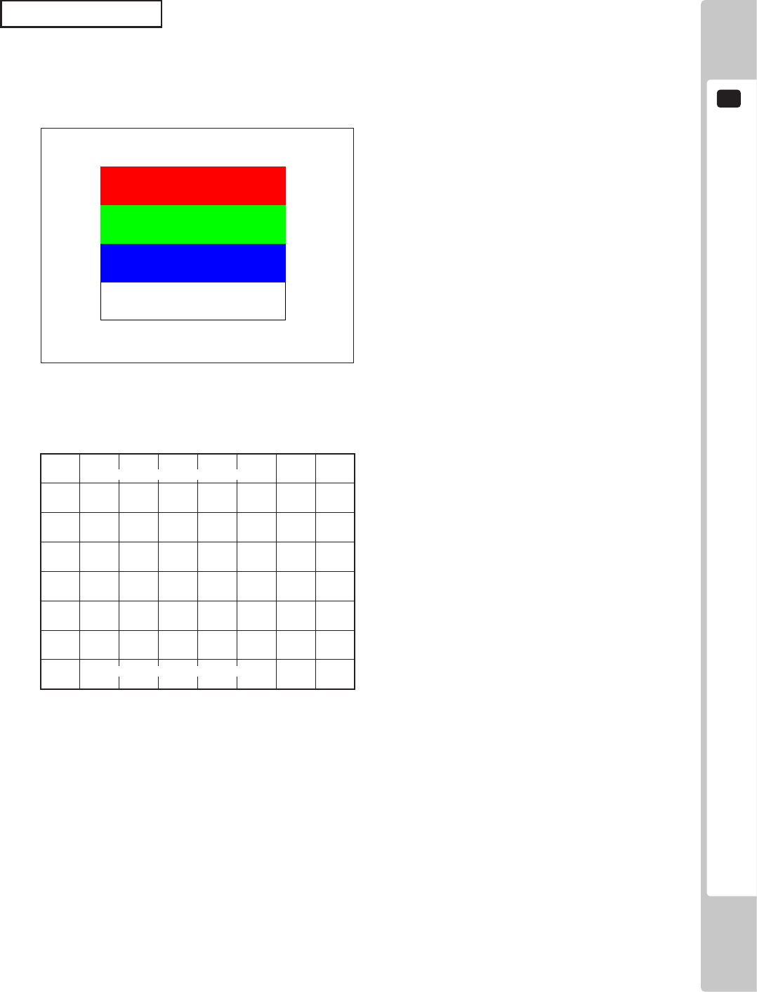
Use MONITOR TEST to check the output of the monitor.
Enter MONITOR TEST and the following color bars will be displayed.
d. MONITOR TEST
Press the TEST Button and the screen will change to the following cross-hatch screen.
Press the TEST Button to return to the System Test Menu screen.
MONITOR TEST 2/2
PRESS TEST TO EXIT
MONITOR TEST 1/2
PRESS TEST TO NEXT
13 2
4
SYSTEM TEST MODE
16
SPEAKER TEST
RIGHT SPEAKER OFF
LEFT SPEAKER OFF
REAR RIGHT SPEAKER OFF
REAR LEFT SPEAKER OFF
CENTER SPEAKER OFF
WOOFER SPEAKER OFF
-> EXIT
SELECT WITH SERVICE AND PRESS TEST
Use SPEAKER TEST to check the output of each speaker by having them each emit a test sound.
Select each speaker with the cursor and press the TEST Button to turn that speaker ON or OFF.
When set to ON a test sound will be emitted from that speaker.
It is possible to set multiple speakers to emit the test sound at the same time.
Some of these options may not be displayed depending on the cabinet being used.
e. SPEAKER TEST
The speakers available to test are as follows.
RIGHT SPEAKER
LEFT SPEAKER
REAR RIGHT SPEAKER
REAR LEFT SPEAKER
CENTER SPEAKER
WOOFER SPEAKER
Move the cursor to EXIT and press the TEST Button to return to the System Test Menu screen.
SYSTEM TEST MODE
4
17
COIN ASSIGNMENTS
COIN CHUTE TYPE COMMON
SERVICE TYPE INDIVIDUAL
COIN CHUTE #1 COIN TO CREDIT RATE
1 COIN(S) COUNT AS 1 CREDIT(S)
COIN CHUTE #2 COIN TO CREDIT RATE
1 COIN(S) COUNT AS 1 CREDIT(S)
DETAIL SETTING
GAME COST SETTING
->EXIT
SELECT WITH SERVICE AND PRESS TEST
f - 1
f - 2
f - 3
f - 4
f - 5
f - 6
Use COIN ASSIGNMENTS to alter the credit settings.
The game will award players the number of credits determined here. Settings will only be saved if they have been
changed.
f. COIN ASSIGNMENTS
COMMON Allow all credits to be used by all players.
INDIVIDUAL Treat each player’s credits individually.
f - 1. COIN CHUTE TYPE
The following information is displayed on this screen.
COMMON
When the COIN CHUTE TYPE is set to COMMON, the number of credits
available to all players will increase by 1.
When the COIN CHUTE TYPE is set to INDIVIDUAL, each player’s
credits will increase by 1.
INDIVIDUAL
When the COIN CHUTE TYPE is set to COMMON, the number of credits
available to all players will increase by 1.
When the COIN CHUTE TYPE is set to INDIVIDUAL, the player
corresponding to the SERVICE Button’s credits will increase by 1.
f - 2. SERVICE TYPE (Service Button Type)
1 COIN(S) COUNT AS 1 CREDIT(S) 1 coin counts as 1 credit
2 COIN(S) COUNT AS 1 CREDIT(S) 2 coins count as 1 credit
3 COIN(S) COUNT AS 1 CREDIT(S) 3 coins count as 1 credit
4 COIN(S) COUNT AS 1 CREDIT(S) 4 coins count as 1 credit
5 COIN(S) COUNT AS 1 CREDIT(S) 5 coins count as 1 credit
1 COIN(S) COUNT AS 2 CREDIT(S) 1 coin counts as 2 credits
1 COIN(S) COUNT AS 3 CREDIT(S) 1 coin counts as 3 credits
1 COIN(S) COUNT AS 4 CREDIT(S) 1 coin counts as 4 credits
1 COIN(S) COUNT AS 5 CREDIT(S) 1 coin counts as 5 credits
FREE PLAY Free play (no coins required)
DETAIL SETTING More detailed settings
f - 3. COIN CHUTE #1 COIN TO CREDIT RATE (Coin and credit conversion rate 1)
4
SYSTEM TEST MODE
18
f - 4. COIN CHUTE #2 COIN TO CREDIT RATE (Coin and credit conversion rate 2)
f - 5. DETAIL SETTING
The following information is displayed on this screen.
COIN CHUTE #1 MULTIPLIER: Coin conversion rate for #1 (How many coins 1 inserted coin counts for)
COIN CHUTE #2 MULTIPLIER: Coin conversion rate for #2 (How many coins 1 inserted coin counts for)
BONUS ADDER: Use of a bonus coin
COIN ASSIGNMENTS
DETAIL SETTING
COIN CHUTE #1 MULTIPLIER
1 COIN COUNT AS 1 COIN(S)
COIN CHUTE #2 MULTIPLIER
1 COIN COUNT AS 1 COIN(S)
BONUS ADDER NO BONUS ADDER
COIN TO CREDIT 1 COIN(S) 1 CREDIT
-> EXIT
COIN CHUTE #1 OPERATION
COIN 1 2 3 4 5 6 7 8 9
CREDIT 1 2 3 4 5 6 7 8 9
COIN CHUTE #2 OPERATION
COIN 1 2 3 4 5 6 7 8 9
CREDIT 1 2 3 4 5 6 7 8 9
SELECT WITH SERVICE AND PRESS TEST
NO BONUS ADDER No bonus coin given
2 COINS GIVE 1 EXTRA COIN 2 coins inserted successively award 1 bonus coin
3 COINS GIVE 1 EXTRA COIN 3 coins inserted successively award 1 bonus coin
4 COINS GIVE 1 EXTRA COIN 4 coins inserted successively award 1 bonus coin
5 COINS GIVE 1 EXTRA COIN 5 coins inserted successively award 1 bonus coin
6 COINS GIVE 1 EXTRA COIN 6 coins inserted successively award 1 bonus coin
7 COINS GIVE 1 EXTRA COIN 7 coins inserted successively award 1 bonus coin
8 COINS GIVE 1 EXTRA COIN 8 coins inserted successively award 1 bonus coin
9 COINS GIVE 1 EXTRA COIN 9 coins inserted successively award 1 bonus coin
COIN TO CREDIT: The number of coins to number of credits conversion rate
Move the cursor to EXIT and press the TEST Button to return to the Coin Assignments screen.
(Can only be set when the COIN CHUTE TYPE is set to COMMON and the COIN setting for the COIN
CHUTE #1 COIN TO CREDIT RATE is set to “1”)
The COIN ASSIGNMENTS DETAIL SETTING screen allows more detailed settings that cannot be performed on
the Coin Setting screen to be performed.
SYSTEM TEST MODE
4
19
COIN ASSIGNMENTS
GAME COST SETTING
* credit(s) to start
* credit(s) to continue
-> EXIT
SELECT WITH SERVICE AND PRESS TEST
f - 6. GAME COST SETTING
Use the COIN ASSIGNMENTS GAME COST SETTING screen to set the cost (number of required credits) that the
game program will use to determine if there are enough credits to play the game.
A total of 8 game costs can be defined. The game cost is defined by the BOOT ID, and when the second boot
recognizes the game, the game cost dened by the BOOT ID will be displayed.
If the game is not recognized, the default game cost will be displayed.
Move the cursor to EXIT and press the TEST Button to return to the Coin Assignments screen.
4
SYSTEM TEST MODE
20
CLOCK SETTING
2007/ 3/ 1(THU) 12:00:00
YEAR
MONTH
DAY
HOUR
MINUTE
SECOND
-> EXIT
SELECT WITH SERVICE AND PRESS TEST
Use CLOCK SETTING to set the date and time.
g. CLOCK SETTING
Use the SERVICE Button to move the cursor to the category that you wish to change and press the TEST Button to
increase that value. Holding the TEST Button down will make the value continuously increase.
Move the cursor to EXIT and press the TEST Button to return to the System Test Menu screen.
SYSTEM TEST MODE
4
21
NETWORK SETTING
NETWORK TYPE MAIN
MAIN NETWORK
NETWORK TEST
-> EXIT
SELECT WITH SERVICE AND PRESS TEST
Use NETWORK SETTING to determine network settings or to test the network.
There is no need to alter these settings for a game that does not use a network.
h. NETWORK SETTING
The following information is displayed on this screen.
h - 1. NETWORK TYPE: MAIN (Sets the type of network to use.)
h - 2. MAIN NETWORK: Sets the LAN port 1.
h - 3. NETWORK TEST: Performs a network test.
Move the cursor to EXIT and press the TEST Button to return to the System Test Menu screen.
h - 1
h - 2
h - 3
4
SYSTEM TEST MODE
22
NETWORK SETTING
MAC ADDRESS **:**:**:**:**:**
DHCP ********
IP ADDRESS
***.***.***.***
SUBNET MASK
***.***.***.***
GATEWAY
***.***.***.***
PRIMARY DNS
***.***.***.***
SECONDARY DNS
***.***.***.***
-> EXIT
SELECT WITH SERVICE AND PRESS TEST
h-2. MAIN NETWORK
Select MAIN NETWORK on the NETWORK SETTING (Setting Menu) and the following screen will be displayed.
• MAC ADDRESS
The individual ID number assigned to each device using the Ethernet.
• DHCP
Set automatic acquisition of network settings.
ENABLE: Acquire network settings automatically.
DISABLE: Input network settings manually.
• IP ADDRESS
A setting required for the network.
After setting the numbers, select SET and press the TEST Button to save the setting.
You cannot select DHCP when ENABLE is selected.
• SUBNET MASK
A setting required for the network.
After setting the numbers, select SET and press the TEST Button to save the setting.
You cannot select DHCP when ENABLE is selected.
• GATEWAY
A setting required for the network. See the manual supplied with each game software for the correct setting.
After setting the numbers, select SET and press the TEST Button to save the setting.
You cannot select DHCP when ENABLE is selected.
• PRIMARY DNS
A setting required for the network. See the manual supplied with each game software for the correct setting.
After setting the numbers, select SET and press the TEST Button to save the setting.
You cannot select DHCP when ENABLE is selected.
• SECONDARY DNS
A setting required for the network. See the manual supplied with each game software for the correct setting.
After setting the numbers, select SET and press the TEST Button to save the setting.
You cannot select DHCP when ENABLE is selected.
SYSTEM TEST MODE
4
23
NETWORK TEST
STATUS ****
CHECKING ***%
DHCP ------ ****
LOOPBACK -- ****
GATEWAY --- ****
SERVER ---- ****
PRESS TEST TO EXIT
h-3. NETWORK TEST
Check the network connection.
The test will begin as soon as this screen is displayed.
If the test ends successfully “GOOD” will be displayed. If the test is unsuccessful “BAD” will be displayed.
If connection is not permitted “N/A” will be displayed.
The results of the test may not be correct immediately after changing the network settings. After exiting the test
mode, restart the cabinet and try again.
Opens the Game Test Mode, allowing game specic settings and tests to be performed.
This option will be displayed in grey until preparations are complete. Select the Game Test Mode option then
perform the exit to begin the game test.
i. GAME TE ST MODE
5
ERROR CODES DISPLAY
24
• If an error code is displayed get on-site maintenance personnel or other
qualied professional to look at it. An unqualied person attempting to resolve
an error code problem may lead to electric shock, short circuit and risk of re.
If no on-site maintenance personnel or qualied professional is available
immediately turn off the power and contact the customer services in this manual
or your supplier.
• If a problem not described in this manual occurs, or the resolution to a problem
described in this manual is not effective, do not make further attempts to resolve
the problem yourself. Immediately turn off the power and contact the customer
services in this manual or your supplier. Any unguided attempts to solve such
problems may lead to a serious accident.
ERROR CODES DISPLAY5
If an error number or message not listed below appears, cease using the product
immediately and send the LINDBERGH RED board in for repairs.
The LINDBERGH RED board is equipped to display various errors on-screen to help solve any problems. If an
error is displayed the game cannot be used. Use the following table of causes and resolutions to solve the problem.
DISPLAY Game Program Not Found.
CAUSE The key chip is not connected.
COUNTERMEASURES Check that the key chip is connected correctly.
Error 1
DISPLAY Game Program Not Available.
CAUSE The key chip is not supported.
COUNTERMEASURES
Check that the key chip from a different system is not inserted.
If that doesn’t x the problem, send the LINDBERGH RED board in for repair
with the key chip still in place.
Error 2
DISPLAY Wrong Region.
CAUSE The game is for a foreign region.
COUNTERMEASURES Use a domestic game.
Error 5
DISPLAY Graphic Card Not Working.
CAUSE The LINDBERGH RED board’s graphic card cannot be found.
COUNTERMEASURES Send the LINDBERGH RED board in for repair with the key chip still in place.
Error 3
DISPLAY I/O Device Not Found.
CAUSE The I/O board inside the LINDBERGH RED cannot be found.
COUNTERMEASURES Send the LINDBERGH RED board in for repair with the key chip still in place.
Error 6

ERROR CODES DISPLAY
5
25
DISPLAY Graphic Card Not Found.
CAUSE The game disk does not support the LINDBERGH RED, or the LINDBERGH
RED board’s graphics card cannot be found.
COUNTERMEASURES Verify that the game disk is compatible with the LINDBERGH RED. If it is,
send the LINDBERGH RED board in for repair with the key chip still in place.
Error 7
DISPLAY System Memory Not Enough.
CAUSE The LINDBERGH RED board does not have enough memory.
COUNTERMEASURES Send the LINDBERGH RED board in for repair with the key chip still in place.
Error 9
DISPLAY Unexpected Game Program Failure.
CAUSE The game program crashed due to an unexpected error.
COUNTERMEASURES Turn the power off and then restart.
Error 10
DISPLAY JVS I/O board is not connected to main board.
CAUSE (1) The I/O board is not connected.
(2) Unreliable connection between the main board and the I/O board.
COUNTERMEASURES
(1) Connect the I/O board to the main board. Verify that the power cable is
connected to I/O board.
(2) Reconnect or replace the JVS cable that connects the I/O board to the main
board.
Error 11
DISPLAY JVS I/O board does not fulll the game spec.
CAUSE The correct I/O board is not connected.
COUNTERMEASURES Use an I/O board that provides the proper input/output for the game.
Error 12
DISPLAY Game Program Not Found.
CAUSE The key chip is not connected.
COUNTERMEASURES Check that the key chip is connected correctly. Check that the key chip from a
different system is not inserted.
Error 15
DISPLAY Game Program Not Found on Game Disk.
CAUSE There is no program image on the game disk.
COUNTERMEASURES Check that a game disk corresponding to the key chip is inserted into the drive.
Error 21
DISPLAY Game Program Not Found on Device.
CAUSE There is no game image on the game installer device.
COUNTERMEASURES Perform a reinstall from the game disk.
Error 22
DISPLAY DVD Drive Not Found.
CAUSE The DVD drive cannot be found.
COUNTERMEASURES Connect the DVD drive.
Error 24
5
ERROR CODES DISPLAY
26
DISPLAY Storage Device is Not Acceptable.
CAUSE The program installer device does not have enough space.
COUNTERMEASURES Send the LINDBERGH RED board in for repair with the key chip still in place.
Error 27
DISPLAY Game Disk Not Found.
CAUSE The game disk cannot be found.
COUNTERMEASURES Insert the game disk.
Error 25
DISPLAY Storage Device Not Found.
CAUSE The program installer device cannot be found.
COUNTERMEASURES Send the LINDBERGH RED board in for repair with the key chip still in place.
Error 26
DISPLAY This Game Disk is Not Acceptable.
CAUSE The game disk cannot be read correctly.
COUNTERMEASURES Exchange the game disk for a proper game disk. Check that the game disk is
not scratched, damaged or dirty.
Error 28
DISPLAY Cannot Control DVD Drive.
CAUSE The DVD drive cannot be controlled.
COUNTERMEASURES The DVD drive may be damaged.
Error 29
DISPLAY Storage Device Not Enough.
CAUSE The program installer device does not have enough space.
COUNTERMEASURES Send the LINDBERGH RED board in for repair with the key chip still in place.
Error 31
DISPLAY Installing Game Program Failed.
CAUSE Transfer of the program failed.
COUNTERMEASURES Check that the DVD drive is connected correctly. Check that the game disk is
not scratched, damaged or dirty.
Error 32
DISPLAY Storage Device is Not Acceptable.
CAUSE The program installer device cannot be found.
COUNTERMEASURES Send the LINDBERGH RED board in for repair with the key chip still in place.
Error 33
DISPLAY Storage Device Not Found.
CAUSE The program installer device cannot be found.
COUNTERMEASURES Send the LINDBERGH RED board in for repair with the key chip still in place.
Error 34
DISPLAY Storage Device is Not Acceptable.
CAUSE The program installer device does not have enough space.
COUNTERMEASURES Send the LINDBERGH RED board in for repair with the key chip still in place.
Error 35
ERROR CODES DISPLAY
5
27
DISPLAY Storage Device May be Broken.
CAUSE The program installer device is broken.
COUNTERMEASURES Send the LINDBERGH RED board in for repair with the key chip still in place.
Error 36
DISPLAY Verifying Game Program Failed.
CAUSE The program image is unveried due to the program image not existing on the
game disk or server.
COUNTERMEASURES Check that the correct game disk is inserted.
Error 37
DISPLAY Server Not Respond.
CAUSE The server is not responding.
COUNTERMEASURES
Check the network settings.
Set IP Address and other settings.
Check that the network cable has not been pulled out.
Error 41
DISPLAY Server Mount Failed.
CAUSE The server directory is could not be reached.
COUNTERMEASURES
Check the network settings.
Set IP Address and other settings.
Check that the network cable has not been pulled out.
Error 42
DISPLAY IP Address Not Assigned.
CAUSE An IP Address could not be obtained from the DHCP server.
COUNTERMEASURES
Check the network settings.
Check that the network cable has not been pulled out.
Check that the DHCP server is running.
Error 43
DISPLAY Game Program Not Found on Server.
CAUSE No program image on the network server.
COUNTERMEASURES Check that the game title, place on the network server, and the key chip
correspond to each other.
Error 44
DISPLAY Wrong Resolution Setting.
CAUSE The game does not support the current resolution settings.
COUNTERMEASURES Change the DIP SW to the correct settings and restart.
Caution 51
DISPLAY Wrong Horizontal/Vertical Setting.
CAUSE The monitor horizontal/vertical settings are incorrect.
COUNTERMEASURES Change the DIP SW to the correct settings and restart.
Caution 52
DISPLAY Server Not Respond.
CAUSE A communications error occurred while the program image was being sent
through the network server.
COUNTERMEASURES Check the network connection, then restart.
Error 45
6
REPLACING THE BUTTERIES
28
REPLACING THE BUTTON BATTERIES6
• Make sure you do not damage the printed board and wires. Such damage can
lead to electric shock, short circuit and re hazard.
• To prevent overheating, explosion, or re:
- Do not recharge, disassemble, heat, incinerate, or short the battery.
- Do not allow the battery to come into direct contact with metallic objects or
other batteries.
- To preserve the battery, wrap it in tape or other insulating material.
• Follow local regulations when disposing of the battery. Improper disposal can
damage the environment.
• Even the site maintenance personnel or other qualied professionals must not
perform replacement operations for parts not described in this manual. In the
event that such work is required either contact the ofce listed in this manual or
rst conrm the procedure with the place or ofce of purchase. Failure to do so
may lead to electric shock or short circuit.
To avoid risk of malfunction and damage:
- Make sure the positive and negative ends are aligned correctly.
- Use only batteries approved for use with this unit.
1
Remove the unit on which the LINDBERGH RED board is placed from the game cabinet. The LINDBERGH
RED board must be removed still attached to the base (wooden shelf, etc.).
The button batteries that require replacement can be found on the main board and on the base board, inside the
LINDBERGH RED board case.
• The batteries in the LINDBERGH RED board can be used for approximately 5
years of standard usage. If the battery appears to require replacement sooner
than 5 years it is more likely that an error has occurred with some other part of
the board. Rather than exchanging the battery requesting repair of the board
itself may be more appropriate.
• Do not touch any internal parts of the board case that are not designated by
SEGA. Also, never perform modications (removal, exchanging, or extension of
parts, etc.) that are not designated by SEGA.
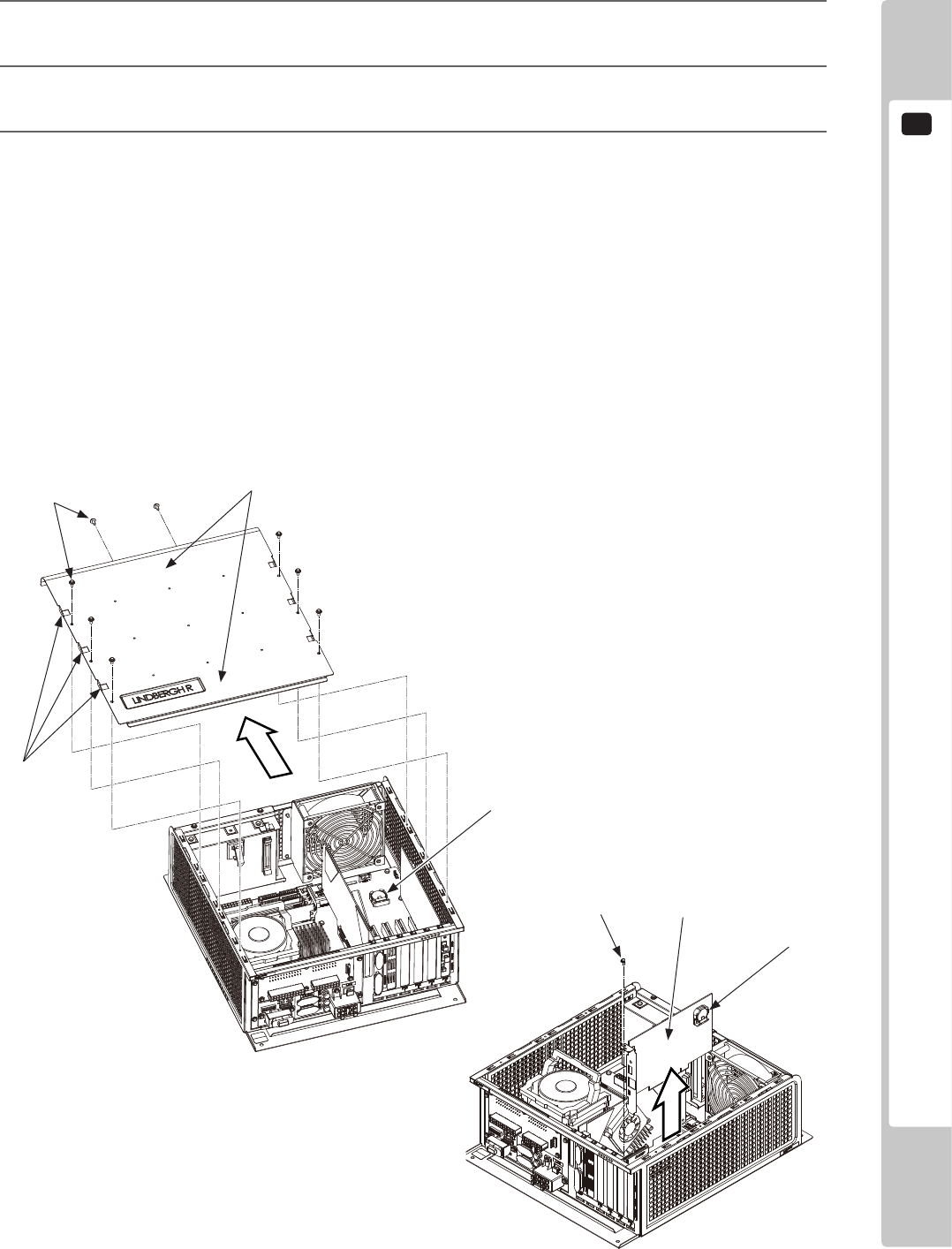
2
Remove eight screws for the LINDBERGH RED board lid.
REPLACING THE BUTTERIES
6
29
3
Press on the front and back of the lid from above and slide toward the side with the fan, releasing the catches
on the left and right sides. Remove the lid.
4
The main board is the board on the bottom of the LINDBERGH RED board case. The button battery is
location close to the fan.
5
The base board is one of the board inserted vertically inside the LINDBERGH RED board case. Remove the
screw holding it in place and lift the board directly upward to remove it. The button battery is on the upper
part of the board.
(1)
(1) SCREW (8), black / M3 x 8, w/at & spring washers
(2) Left (and right) side lid catches
(3) Press here and slide toward fan
(4) BUTTON BATTERY (BATTERY CR2032 1F MATSUSHITA) / 401-0054
(5) SCREW (1), black/M3 x 8, w/at & spring washers
(6) BASE BOARD
(7) BUTTON BATTERY (BATTERY CR2032 1F MATSUSHITA) / 401-0054
(3)
(4)
(5)
(6)
(2)
(7)
(6)
