Arcade Outrun 2 Sp Dlx Manual ORP Deluxe User
2013-11-21
User Manual: Arcade Outrun 2 Sp Dlx Manual
Open the PDF directly: View PDF ![]() .
.
Page Count: 151 [warning: Documents this large are best viewed by clicking the View PDF Link!]

420-6830-01UK REV 0
SERVICE MANUAL
TM
DELUXE
Before using this product, read this SERVICE MANUAL carefully to understand the contents stated herein.
After reading this manual, be sure to keep it available nearby the product or somewhere convenient in
order to be able to refer to it whenever necessary.
Manufactured in the UK by
MANUFACTURING DIVISION (U.K.)
i
CONTENTS
1. BEFORE USING THIS PRODUCT .......................................................................................................4
1.1. Inspections Immediately After Transporting The Product To The Location ......................................5
2. INTRODUCTION TO THIS SERVICE MANUAL...................................................................................7
3. INSTALLATION AND SERVICE INSTRUCTIONS ...............................................................................8
3.1. Handling And Installation Precautions ...............................................................................................8
3.2. Coin Handling.....................................................................................................................................9
3.3. Name of Parts ....................................................................................................................................9
3.4. Accessories......................................................................................................................................10
3.5. How To Use The Chihiro Board Carton Box....................................................................................11
3.5.1. Instructions................................................................................................................................11
3.6. How To Use The Carton Box (GD-ROM Drive) ...............................................................................13
3.7. Assembly Instructions ......................................................................................................................14
3.8. Assembling The POP To Billboard ..................................................................................................16
3.9. Assembling The Billboard To PTV...................................................................................................17
3.10. Assembling PTV To Main Cabinet ...............................................................................................18
3.11. Assembling The Coin Tower ........................................................................................................20
3.12. Securing In Place .........................................................................................................................21
3.13. Coin Handling Installation.............................................................................................................22
3.13.1. Wiring connections................................................................................................................23
3.14. Turning On The Power .................................................................................................................24
3.15. Assembly Check...........................................................................................................................25
3.15.1. Memory Test .........................................................................................................................25
3.15.2. CRT Test ...............................................................................................................................26
3.16. Moving The Machine ....................................................................................................................27
3.17. Fuses............................................................................................................................................28
3.18. Maintenance .................................................................................................................................29
3.18.1. Handle Mecha .......................................................................................................................30
3.18.1.1. Access To The Handle Mecha’s VR .................................................................................30
3.18.1.2. Replacing and Adjusting The Handle Mecha’s V.R. .........................................................30
3.18.1.3. Adjusting the VR................................................................................................................31
3.18.1.4. Replacing the VR ..............................................................................................................31
3.18.1.5. Greasing............................................................................................................................32
3.18.2. Accelerator & Brake ..............................................................................................................33
3.18.2.1. Removing the Accelerator & Brake...................................................................................33
3.18.2.2. Adjusting the V.R...............................................................................................................34
3.18.2.3. Replacing the V.R. ............................................................................................................35
3.18.2.4. Greasing............................................................................................................................35
3.18.3. Paddle Shift ...........................................................................................................................36
3.18.3.1. Replacing Paddle Shift Microswitches. .............................................................................36
3.18.4. Replacement Of Fluorescent And Other Lamps...................................................................38
3.18.4.1. Fluorescent Lamp Replacement .......................................................................................38
3.18.4.2. Start / View Change Bulb Replacement............................................................................39
3.18.4.3. Brake Light Bulb Replacement..........................................................................................40
3.18.4.4. LED Strip Replacement.....................................................................................................40
3.18.5. Cleaning The Cabinet Surfaces ............................................................................................41
3.18.6. Seat (Greasing To Seat Rail Portion) ...................................................................................41
3.19. Troubleshooting............................................................................................................................42
3.19.1. Troubleshooting (When No Error Message Is Shown) .........................................................42
3.20. Game Board .................................................................................................................................45
3.20.1. Removing The Game Board Assembly.................................................................................45
3.20.2. Removing The GD-ROM Drive .............................................................................................46
3.20.3. Removing The Game Board .................................................................................................47
3.20.4. Composition of the Game Board...........................................................................................48
3.20.4.1. Replacing The Main Board Battery ...................................................................................49
3.20.4.2. Replacing The Media Board Battery Pack ........................................................................50
3.20.5. Shipping The Game Board....................................................................................................53
3.20.6. Shipping The Media Board....................................................................................................55
3.20.7. Shipping The GD-ROM Drive................................................................................................56
3.20.8. Machine Set Up.....................................................................................................................57
3.20.8.1. Network Play .....................................................................................................................58
3.21. Periodic Check and Inspection.....................................................................................................63
ii
4. GAME DESCRIPTION.........................................................................................................................64
4.1. Basic Controls ..................................................................................................................................65
4.2. Game Outline ...................................................................................................................................66
4.3. Setup Screen Order And Contents ..................................................................................................67
4.3.1. Versus Mode Entry ...................................................................................................................67
4.3.1.1. Closing Versus Mode Entry ...............................................................................................67
4.3.2. Single Player Setup ..................................................................................................................68
4.3.2.1. (1) Player’s Car Selection..................................................................................................68
4.3.2.2. Changing the Car Colour...................................................................................................68
4.3.2.3. Transmission Selection .....................................................................................................69
4.3.2.4. Game Mode Selection .......................................................................................................70
4.3.2.5. Game Mode Selection – 15 Continuous Course Mode.....................................................71
4.3.2.6. Settings Selection (Time Attack Mode only)......................................................................72
4.3.2.7. BGM Selection...................................................................................................................73
4.3.3. Versus Play Setup ....................................................................................................................75
4.3.3.1. Versus Stage Selection .....................................................................................................75
4.3.3.2. Versus Stage Selection (15-Continuous Course Mode) ...................................................76
4.3.3.3. Player's Car Selection .......................................................................................................77
4.3.3.4. Transmission Selection .....................................................................................................78
4.3.3.5. BGM Selection...................................................................................................................78
4.3.4. Special Controls........................................................................................................................78
4.4. Game Instructions ............................................................................................................................79
4.4.1. Common Features in All Modes ...............................................................................................79
4.4.1.1. Display Breakdown (All Modes).........................................................................................79
4.4.1.2. Game Controls (All Modes) ...............................................................................................80
4.4.2. Single Player: OutRun Mode ....................................................................................................81
4.4.2.1. Display Breakdown............................................................................................................81
4.4.2.2. Game Instructions..............................................................................................................81
4.4.3. Single Player: Heart Attack Mode.............................................................................................82
4.4.3.1. Display Breakdown............................................................................................................82
4.4.3.2. Game Instructions..............................................................................................................82
4.4.4. Single Player: Time Attack Mode..............................................................................................83
4.4.4.1. Display Breakdown............................................................................................................83
4.4.4.2. Game Instructions..............................................................................................................83
4.4.5. Versus Play...............................................................................................................................85
4.4.5.1. Display Breakdown............................................................................................................85
4.4.5.2. Game Instructions..............................................................................................................85
4.4.6. 15-Continuous Course Mode....................................................................................................86
4.4.6.1. Display Breakdown............................................................................................................86
4.4.6.2. Game Instructions..............................................................................................................86
4.4.7. Game Pause .............................................................................................................................87
4.5. Name Entry And Internet Ranking ...................................................................................................88
4.5.1. 1. Name Entry ...........................................................................................................................88
4.5.2. Internet Ranking........................................................................................................................89
4.6. Character Introductions....................................................................................................................90
5. MAINTENANCE INSTRUCTIONS ......................................................................................................91
5.1. Explanation of Test and Data Display..............................................................................................91
5.2. VTS Assembly..................................................................................................................................92
5.3. System Test Mode ...........................................................................................................................93
5.3.1. System Test Menu Mode..........................................................................................................93
5.3.1.1. Media Board Test ..............................................................................................................94
5.3.1.2. System Information............................................................................................................95
5.3.1.3. JVS Test ............................................................................................................................96
5.3.1.4. Sound Test ........................................................................................................................98
5.3.1.5. C. R. T. Test ......................................................................................................................99
5.3.2. System Assignments ..............................................................................................................100
5.3.2.1. Coin Assignments............................................................................................................100
5.3.2.2. Coin/Credit Setting (Coin Chute Common Type) ............................................................101
5.3.2.3. Coin/Credit Setting (Coin Chute Individual Type)............................................................102
5.3.2.4. Manual Setting.................................................................................................................103
5.3.2.5. Sequence Setting ............................................................................................................104
5.3.2.6. Bookkeeping....................................................................................................................105
5.3.2.7. Backup Data Clear ..........................................................................................................107
iii
5.3.2.8. ROM BD Test ..................................................................................................................108
5.3.2.9. Clock Setting....................................................................................................................108
5.4. Game Test Mode ...........................................................................................................................109
5.4.1. Input Test ................................................................................................................................110
5.4.2. Output Test .............................................................................................................................111
5.4.3. Drive Board Test.....................................................................................................................112
5.4.4. Game Assignments.................................................................................................................113
6. DESIGN RELATED PARTS ..............................................................................................................116
7. PARTS LIST ......................................................................................................................................117
7.1. Assembly Structure ........................................................................................................................117
7.2. ORP-0000UK TOP ASSY OUTRUN SPECIAL TOURS DX........................................................118
7.3. ORP-1000UK ASSY PTV.............................................................................................................119
7.4. NCR-0600UK ASSY FRONT PANEL ..........................................................................................120
7.5. ORP-2000UK ASSY MAIN CABI .................................................................................................121
7.6. ORP-2050UK ASSY FRONT CABI..............................................................................................122
7.7. ORP-2070UK ASSY AC UNIT .....................................................................................................125
7.8. ORP-2027UK CONTROL PANEL COVER R ..............................................................................126
7.9. ORP-2028UK ASSY BULK BOARD COVER ..............................................................................127
7.10. ORP-2080UK ASSY CTRL PANEL COVER F ........................................................................128
7.11. ORP-2350UK ASSY REAR CABI ............................................................................................129
7.12. ORP-3020UK ASSY BASE BOX..............................................................................................131
7.13. ORP-2260UK FLOOR CENTRE ASSY....................................................................................132
7.14. ORP-4000UK ASSY MAIN BD.................................................................................................133
7.15. ORP-6001UK ASSY CABLE RUN ...........................................................................................134
7.16. ORP-4100UK ASSY AMP BD ..................................................................................................135
7.17. ORP-4200UK ASSY ELEC BD ................................................................................................136
7.18. ORP-2400UK ASSY SEAT.......................................................................................................137
7.19. ORP-3000UK ASSY FRAME BASE.........................................................................................139
7.20. ORP-INST-D ASSY INSTALLATION KIT ORP DX..................................................................140
7.21. ORP-0500UK ASSY BILLBOARD............................................................................................141
7.22. ORP-3100UK ASSY COIN CHUTE TOWER...........................................................................142
8. APPENDIX A - ELECTRICAL SCHEMATIC .....................................................................................143
8.1. WIRE COLOURS ...........................................................................................................................143
8.2. ELECTRICAL SCHEMATIC...........................................................................................................143
4
1. BEFORE USING THIS PRODUCT
To ensure the safe usage, be sure to read the following before using the product. The following instructions are
intended for the use of QUALIFIED SERVICE PERSONNEL ONLY.
If any activity is carried out on the product, this should be done only after carefully reading and sufficiently
understanding the instructions.
Only qualified service personnel should carry out maintenance on the product.
Depending on the potential risk, terms such as” WARNING!” “CAUTION” and “IMPORTANT!” are used where an
explanation is given that requires special attention. SEGA is not responsible for injury or damage caused by use in a
manner contrary to the instructions given in this document.
In order to prevent accidents warning stickers and printed instructions are applied in the places where a potentially
hazardous situation relating to the product could arise. Be sure to comply with these warnings.
Indicates that mishandling the product by disregarding this warning will cause a potentially
hazardous situation that can result in death or serious injury.
Indicates that mishandling the product by disregarding this caution will cause a potentially
hazardous situation that can result in personal injury and or material damage.
This is cautionary information that should be complied with when handling the product.
Indicates that mishandling the product by disregarding this will cause a potentially hazardous
situation that may not result in personal injury but could damage the product.
Be sure to turn off the power and disconnect from the mains supply before working on the machine.
Ensure that the correct fuses are fitted to the machine. Details of these are enclosed in the Service Manual.
Ensure that only qualified Service Engineers perform any maintenance work on the machine.
Specification changes, removal of equipment, conversion and/or additions not designated by SEGA are not permitted
and will invalidate this product’s CE conformity.
Warning labels or safety covers for personal protection etc, are component parts of the product. A potential hazard will
be created if the machine is operated while any parts have been removed. Do not operate the product if any doors, lids
or protective covers become damaged or lost. SEGA is not liable in any whatsoever for any injury and/or damage
caused by specification changes not designated by SEGA.
Before installing the product, check for the Electrical Specification Sticker, SEGA products have a sticker on which the
electrical specifications are detailed. Ensure that the product is compatible with the power supply voltage and frequency
requirements of the location in which the machine is to be installed.
Install and operate the machine only in places where appropriate lighting is available, allowing warning stickers to be
clearly read.
To ensure maximum safety for customers and operators, stickers and printed instructions describing potentially
hazardous situations are applied to potentially hazardous locations. Ensure that the product’s operating location has
sufficient lighting to allow any warnings to be read. If any sticker or printed warning is removed or defaced, do not
operate the machine until an identical item has replaced it.
Exercise great care when handling the monitor (applies only to product with monitor). Some of the monitor (TV) parts
are subject to high-tension voltage. Even after turning the power off some components are liable to high-tension
voltage. Only qualified service engineers should perform monitor repair and replacement.
In cases where commercially available monitors and printers are used, only the items relating to this product are
contained in this manual. Some commercially available equipment will have functions and reactions not referred to in
this manual. This manual should be read in conjunction with the specific manufacturer’s manual for such equipment.
Descriptions contained herein may be subject to change without prior notification.

5
The contents described herein are fully prepared with due care. However, should any question arise or errors be found
please contact SEGA AMUSEMENTS EUROPE LTD.
Descriptions contained herein may be subject to change without prior notification.
The contents described herein are fully prepared with due care. However, should any question arise or
errors be found please contact SEGA.
1.1. Inspections Immediately After Transporting The Product To The
Location
• Only QUALIFIED SERVICE PERSONNEL should carry out inspection.
Normally, at the time of shipment, SEGA products are in a state to allowing usage immediately after
transporting to the location. Nevertheless, an irregular situation may arise during transportation preventing
this. Before turning on the power, check the following points to ensure that the product has been
transported safely.
• Are then any dented parts or defects (cuts, etc.) on the external surfaces of the product.?
• Are castors and leg adjusters present and undamaged?
• Do the power supply voltage and frequency requirements meet with the local supply?
• Are all wiring connectors correctly and securely connected? Unless connected in the correct
direction, connector connections cannot be made successfully. Do not insert connectors forcibly.
• Are all IC’s of each IC BD firmly inserted?
• Does the power cord have any cuts or dents?
• Do fuses meet the specified rating?
• Are such units such as monitors, control equipment, IC BD, etc. firmly secured?
• Are all earth wires connected?
• Are all accessories available?
• Can all doors and lids be opened with the accessory keys and/or tools?
6
CONCERNING THE STICKER DISPLAY CONCERNING WARNING STICKERS
SEGA product has stickers describing the product
manufacture number (Serial Number) and
electrical specification. If you require service
assistance you will require the Serial Number.
Identical machines may have different parts fitted
internally. Only by quoting the Serial Number will
the correct parts be identified.
SEGA product has warning displays on
stickers, labels or printed instructions
adhered/attached to or incorporated in the
places where hazardous situations can arise.
The warning displays are intended for the
accident prevention of customers and service
personnel.
SPECIFICATIONS
Installation Space: 1280 x 2850 mm
Height: 2500mm (with POP) 2050mm (without POP)
Rated Voltage: 230VAC
Rated Current: 3A
Operating Temperature Range 5-30°C
Note: Descriptions in this manual are subject to change without prior notice.
7
2. INTRODUCTION TO THIS SERVICE MANUAL
SEGA ENTERPRISES LTD., supported by its experience in electronic high technology of VLSI’s,
microprocessors etc. and with a wealth of experience, have for more than 30 years been supplying various
innovative and popular games to the world market. This Service Manual is intended to provide detailed
descriptions together with all the necessary information covering the general operation of electronic
assemblies, electromechanicals, servicing controls, spare parts, etc. as regards OUTRUN 2 SPECIAL
TOURS DELUXE, a new SEGA product. This manual is intended for those who have knowledge of
electricity and technical expertise especially in IC’s, CRT’s, microprocessors etc. Carefully read this manual
to acquire sufficient knowledge before working on the machine. Should there be any malfunction, non-
technical personnel should under no circumstances touch the interior systems. Should such a situation
arise contact the nearest branch listed below or our head office.
SEGA AMUSEMENTS EUROPE LTD./ SEGA SERVICE CENTRE
Suite 3a
Oaks House
12 - 22 West Street
Epsom
Surrey
United Kingdom
KT18 7RG
Telephone: +44 (0) 1372 731820
Fax: +44 (0) 1372 731849
8
3. INSTALLATION AND SERVICE INSTRUCTIONS
• Only QUALIFIED SERVICE PERSONNEL should carry out installation and
commissioning.
3.1. Handling And Installation Precautions
When installing or inspecting the machine, be very careful of the following points and pay attention to
ensure that the player can enjoy the game safely.
The game must NOT be installed under the following conditions:
• Outside, the game is designed for indoor use only.
• In areas directly exposed to sunlight, high humidity, dust, excessive heat or extreme cold.
• In locations that would present an obstacle in the case of an emergency i.e. near fire equipment or
emergency exits.
• On unstable surfaces or surfaces subject to vibration.
• Where liquids, other than routine cleaning, may come into contact with the game.
Important:
• This machine should only be installed by Qualified Service Personnel.
• Be sure to switch the supply power OFF and remove the mains supply plug from the machine
before any work is carried out on the machine.
• Do not attempt to repair the PCB’s (Printed Circuit Boards) yourself. This will void the warranty. The
PCB’s contain static sensitive devices that could be damaged.
• Always return a faulty part to your distributor with adequate packaging and protection.
• When removing the plug from the mains always grasp the plug not the cable.
• Do not use a fuse that does not meet the specified rating.
• Make sure all connections are secure before applying power.
• Ensure that the mains lead is not damaged. If the mains lead is damaged in any
way there could be a danger of electric shock or a fire hazard.
• Ensure that the power supply is fitted with circuit protection. Using the power
supply without circuit protection is a fire hazard.
9
3.2. Coin Handling
Standard Sega machines are fitted with a SR3 coin mechanism, however, as a service to our customers
Sega machines can be supplied with no coin mechanism or door allowing the customer to fit a coin
handling option from the approved list. Fit only the coin handling arrangements detailed below and follow
the instructions provided in Section 3.13. Failure to fit the coin handling options detailed or failure to follow
the installation instructions will render the machine, under the CE marking directive, void.
Approved coin handling options:
• Generic mechanical
• Mars (MS111B1 and ME115)
• SECI RM4-G20
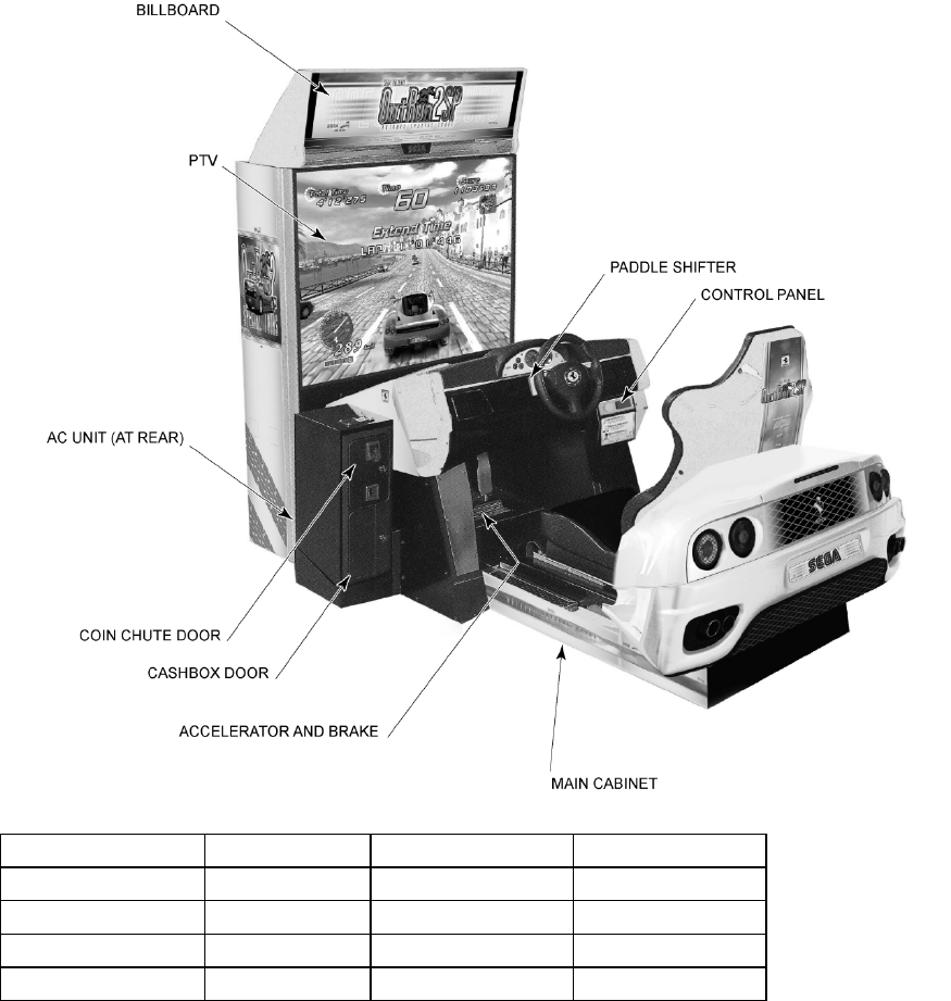
3.3. Name of Parts
Width (mm) Length (mm) Height (mm)
PTV 1220 600 1700
MAIN CABINET 1280 2000 1200
BILLBOARD 1220 400 350 (POP 450)
When Assembled 1280 2700 2050 (POP 2500)
10
3.4. Accessories
The machine is supplied with an installation kit. Please ensure the following parts are supplied:
ITEM PART NO. QTY DESCRIPTION
1 ORP-3100UK 1 ASSY COIN CHUTE TOWER
2 ORP-0500UK 1 ASSY BILLBOARD
4 NCR-0002 2 JOINT BRKT CENTER
6 ORP-0512UK 1 POP PANEL ORP DX
7 ORP-0513UK 1 POP BRKT
8 ORP-3011UK 1 TOWER BASE
9 ORP-0001UK 1 JOINT BRKT FRONT CABI L
10 ORP-0002UK 1 JOINT BRKT FRONT CABI R
20 422-0932DUK 1 PLAY INSTR SH ORP DX MULTI
23 440-CS0186UK 1 STICKER C EPILEPSY MULTI
201 030-000830-SB 14 M8X30 BLT W/S BLK
202 068-852216-0B 14 M8 WSHR 22OD FLT BLK
203 060-F00800 3 M8 WSHR FORM A FLT PAS
207 060-F00600 2 M6 WSHR FORM A FLT PAS
209 050-F00600 2 M6 NUT FLG SER PAS
212 030-000860-SB 3 M8X60 BLT W/S BLK
213 000-P00516-WB 2 M5X16 MSCR PAN W/FS BLK
214 000-P00412-WB 6 M4X12 MSCR PAN W/FS BLK
215 068-441616-0B 6 M4 WSHR 16OD FLT BLK
401 PK0369 1 INST KIT BOX ORP DX
402 OS1019 3 SELF SEAL BAG 9X12.3/4
408 509-5387 1 SW MICRO TYPE (AH71557K)
409 220-5484 1 VOL CONT B-5K OHM
411 600-7269-0500 1 LAN CABLE 500CM
412 420-6830-01UK 1 SERVICE MANUAL ORP DX
413 540-0006-01 1 WRENCH M4 TMP PRF
416 540-0007-01 1 WRENCH M5 TMP PRF
417 540-0009-01 1 WRENCH M8 TMP PRF
418 SAECE-xxx 1 DECLARATION OF CONFORMITY
Item 413-417 - Tamper-proof TORX wrench.

11
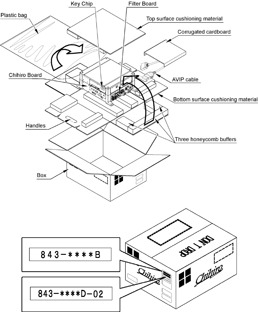
3.5. How To Use The Chihiro Board Carton Box
Replacement or repair of the Game Board (Chihiro) for this product should be
undertaken at the appropriate repair centre. Be sure to follow the specifications
below when requesting repairs/sending the board to the repair centre. Not following
the specifications may result in the board not being accepted or in extra charges
being made.
• Put the game board in the carton box as is. Do not carry out any
disassembly or part removal other than that specified.
• Follow the procedure and instructions regarding direction below when
placing the Game Board in the carton box.
• When packing the game board with the Media Board attached, do not
remove the Key Chip.
• When packing the game board with the Media Board detached, be sure to
include the AVIP Cable.
• When packing, attach the accessory stickers in the specified places on the
Game Board and carton box.
3.5.1. Instructions
1. Wrap the Chihiro Board in a plastic bag.
2. Place it on top of the bottom surface cushioning material. Turn the Filter Board to face the side with
the three honeycomb buffers. Placing it in the opposite direction may cause damage to the Filter
Board.
3. Insert corrugated cardboard into the space between the lateral honeycomb buffers of the bottom
surface cushioning material and stow the AVIP cable inside.
4. Place the Chihiro Board wrapped in the bottom surface cushioning material into the carton box.
Use the handles on the bottom surface cushioning material.
5. Place the upper surface cushioning material on top of the Chihiro Board. Be sure to align it in the
right direction, as it will not fit otherwise.
6. Close the top of the carton box and seal it tightly with adhesive tape.
12
13
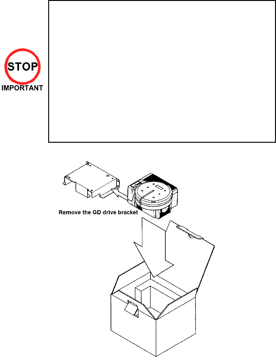
3.6. How To Use The Carton Box (GD-ROM Drive)
When you want to order for replacing or repairing service of the GD-ROM drive that
is used by the product, pack it in a carton box as instructed below, and then deliver
the carton box to a service agent. If you do not observe the instruction, your order
may not be accepted or may be charged additionally. If you handle the GD-ROM
drive differently from the following instructions, its components may be damaged.
• Contain the GD-ROM drive in a dedicated carton box. Do not disassemble it
or remove any part from it unless otherwise instructed.
• Before containing the GD-ROM drive in a dedicated carton box, attach the
GD-ROM drive lid (DISC LID) onto the drive and fix the lid with a screw.
• Before containing the GD-ROM drive in a dedicated carton box, remove the
GD-ROM disc from the drive. Do not attempt to move the GD-ROM drive
with a GD-ROM disc inside.
• Before containing the GD-ROM drive in a dedicated carton box, remove the
GD-ROM drive bracket. Carefully keep the GD-ROM drive bracket and the 4
set screws, because they will be reused.
• When inserting the GD-ROM drive into a dedicated carton box, be careful
about an inserting direction as illustrated below.
• The packing materials in a carton box are used as a cushion. Use them
always when inserting the GD-ROM drive into a dedicated carton box. Do
not bend them.

14
3.7. Assembly Instructions
• Perform assembly work by following the procedure herein stated. Failing to
comply with the instructions can cause electric shock hazard.
• Perform assembling as per this manual. Since this is a complex machine,
erroneous assembling can cause an electric shock, machine damage and
or not functioning as per specified performance.
• When assembling, be sure to use plural persons. Depending on the
assembly work, there are some cases in which working by one person
alone can cause personal injury or parts damage.
• Ensure that connectors are accurately connected. Incomplete connections
can cause electric shock hazard.
• Be careful not to damage the wires. Damaged wires may cause electric
shock or short circuit or present a fire risk.
• Do not carelessly push the PTV. Pushing the PTV carelessly can cause
the PTV to fall down.
• This work should be performed by the site maintenance individual or other
skilled professional. Performing work by non-technical personnel can
cause a severe accident such as electric shock. Failing to comply with this
instruction can cause a severe accident such as electric shock to the player
during operation.
• Provide sufficient space so that assembling can be performed. Performing
work in places with narrow space or low ceiling may cause an accident and
assembly work to be difficult.
• To perform work safely and avoid serious accident such as the cabinet's
falling down, do not perform work in places where step-like grade
differences, a ditch, or slope exist.
• Do not use this product with connectors other than those that were
connected and used with the Game Board at the time of shipping. Do not
carelessly connect wires to connectors that were not used at the time of
shipping, as this may cause overheating, smoke or fire damage.
• When handling plastic parts, use care. Do not give a shock or apply
excessive load to the fluorescent lamps and plastic parts. Failure to
observe this can cause parts damage, resulting in injury due to fragments,
cracks and broken pieces.
• To perform work safely and securely, be sure to prepare a step which is in
a secure and stable condition. Performing work without using the step can
cause violent falling down accidents.
• Make sure that the GD cable connector is inserted parallel to the plug.
Improper insertion may cause damage to the connector and present a fire
risk.
15
When carrying out the assembly work, follow the procedure in the following 6 item sequence
STEP 1 ASSEMBLING POP TO THE BILLBOARD
STEP 2 ASSEMBLING THE BILLBOARD TO PTV
STEP 2 ASSEMBLING PTV TO MAIN CABINET
STEP 3 ASSEMBLING THE COIN TOWER
STEP 4 SECURING IN PLACE
STEP 5 COIN HANDLING INSTALLATION
STEP 6 TURNING ON THE POWER
STEP 7 ASSEMBLY CHECK
Note that the parts contained within the installation kit are required for the assembly work.
16
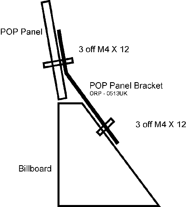
3.8. Assembling The POP To Billboard
1. Fix the POP Panel Bracket to the Billboard using three M4 x 12 screws with black washers on front.
2. Fix the POP Panel to the POP Panel Bracket using three M4 x 12 screws with black washers.
17
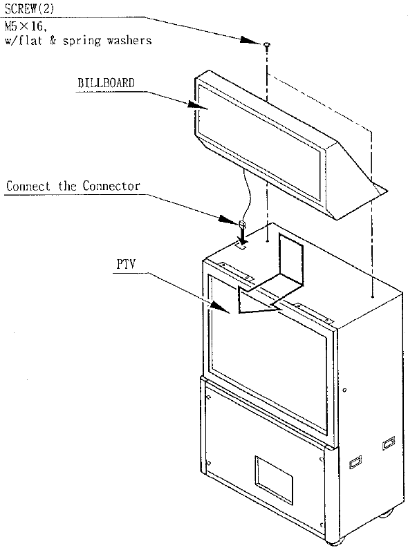
3.9. Assembling The Billboard To PTV
1. The Billboard should be installed using three or more workers. Two workers should support the
Billboard on top of the PTV in an inclined position, while a third worker makes the Billboard power
connection. A suitable step should be used to ease access to the Billboard power connection.
2. Engage the Billboard onto the brackets at the front, and secure using the two screws provided at the
rear.
18
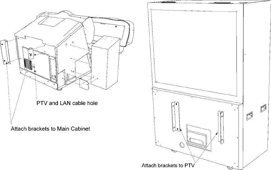
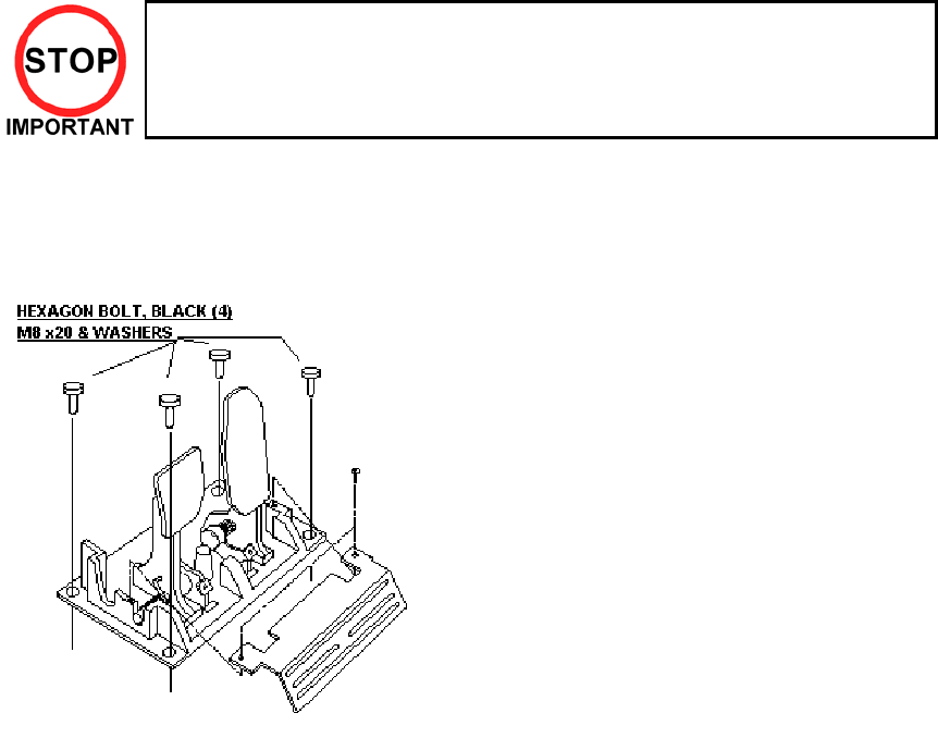
3.10. Assembling PTV To Main Cabinet
Before you can connect the PTV and Main Cabinet Assembly together, you have fix two connecction
brackets to each assembly.
1. Fix the connection brackets to the Main Cabinet Assembly using four M8 screws.
2. Fix the connection brackets to the PTV using four M8 screws.
Note: Removal of rear door may be necessary to
facilitate the routing of the PTV harnesses.
3. Move the Main Cabinet and PTV together, close enough to facilitate connection of the video and
power harnesses (stored in the Main Cabinet). Take great care when manoeuvring the PTV as it can
be unstable when not secured to the Main Cabinet.
4. Connect these harnesses to their respective sockets on the Connector Panel on the front of the PTV.
Observe correct orientation of the connectors when inserting, to avoid damage. Fasten the fixing
screws on the video connector once inserted.
19
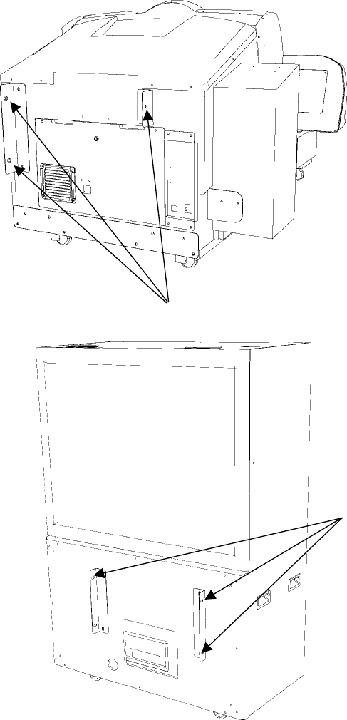
5. Carefully slide the Main Cabinet and PTV together until the joint rackets overlap.
6. Use three M8 bolts to lock the brackets together.
Three M6 fixing holes
Three M6 fixing holes
20
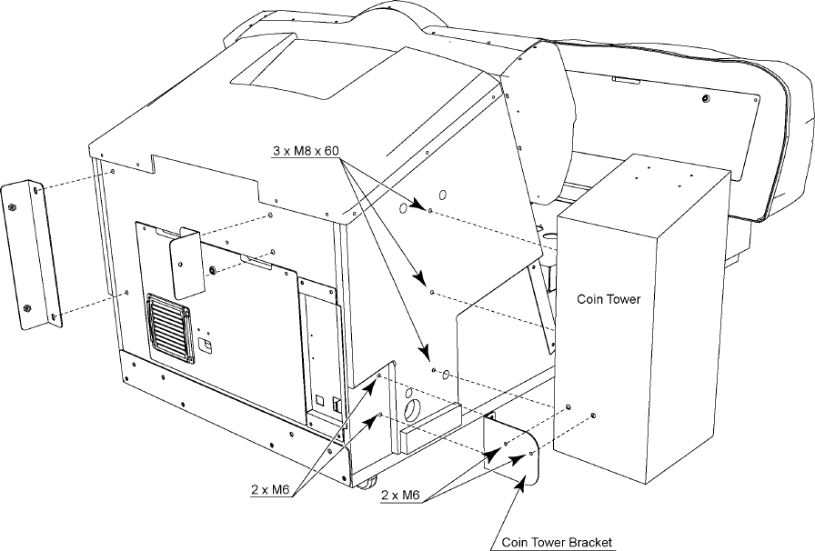
3.11. Assembling The Coin Tower
1. Fix the Coin Tower Bracket to the Main Cabinet Assembly using two M6 screws.
2. Fix the Coin Tower to the Main Cabinet Assembly using three M8 screws.
3. Fix the Coin Tower to the Coin Tower Bracket using two M6 nuts and washers.
21
3.12. Securing In Place
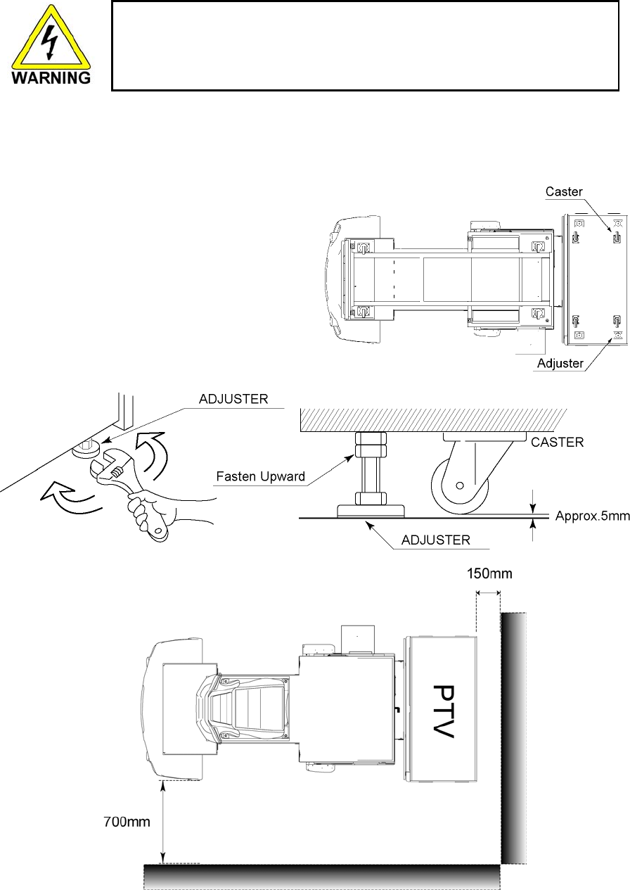
• Make sure that all of the adjusters are in contact with the floor. If they are
not, the cabinet can move and cause an accident.
This product has 8 casters (4 for PTV Base, 4 for MAIN CABINET) and 10 Adjusters (4 for PTV Base, 6 for
MAIN CABINET). When the installation position is determined, cause the adjusters to come into contact
with the floor directly, make adjustments in a manner so that the casters will be raised approximately 5 mm.
from the floor and make sure that the machine position is level.
1. Transport the product to the installation
position.
2. Have all of the adjusters make contact with
the floor. Adjust the adjuster's height by
using a wrench so that the machine position
is kept level. When contacting the adjusters
of the right and left fences onto the floor,
manually turn them.
3. After making adjustment, fasten the adjuster
nut upward and secure the height of
adjuster.
Leave a gap for access and ventilation.

22
3.13. Coin Handling Installation
• Only QUALIFIED SERVICE PERSONNEL should carry out this operation.
When fitting the coin mechanism to the door please refer to the specific manufacturers installation
instructions for that coin mechanism.
23
3.13.1. Wiring connections
COIN MECH LOOM INSTALLATION
C220B LM1006IDC
LM1006LAMP-0.1
• Attach the lamp holder to the bracket on the coin
return button.
• Attach one 15-way connector to the C220 coin
mech.
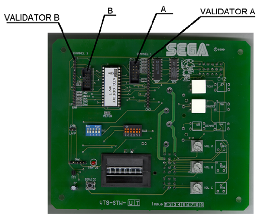
• Attach the other 15-way connector to Validator A
on the credit board.
• Attach the 2-way connector to ‘LAMP’ on the VTS
board.
GENERIC
MECHANICALS
LM1008
LM1008-LAMP
• Fit the two lamp holders behind the coin return
buttons.
• Attach the blue cable and orange cable to one
mech’s microswitch switch.
• Attach the blue/green cable and orange/green
cable to the other mech’s microswitch.
• Attach the 2-way mate and lok plug to the 2-way
mate and lok cap provided.
• Attach one 15-way connector to Validator A and
the other to Validator B on the credit board
MARS
MS111B1
MARS ME115
LM1007
LM1008-LAMP
• Fit the lamp holder to the bracket behind the coin
return button.
• Fit one of the 13-way connectors to the coin mech.
• Fit the other 13-way connector to Validator A on
the credit board. Note the 13-way connector is
keyed and this key must coincide with the key on
the credit board.
SECI, C120,
SR3
OWN LOOM AND
LM1006LAMP-0.1
• Attach the lamp holder to the bracket on the coin
return button.
• Attach the 2- connector to ‘LAMP’ on the VTS
board.
• Attach the validator’s own loom to position A on the
credit board
24
3.14. Turning On The Power
• Be sure that the machine is not already connected to the mains supply
before attempting this operation
• This operation should only be carried out by QUALIFIED SERVICE
PERSONNEL
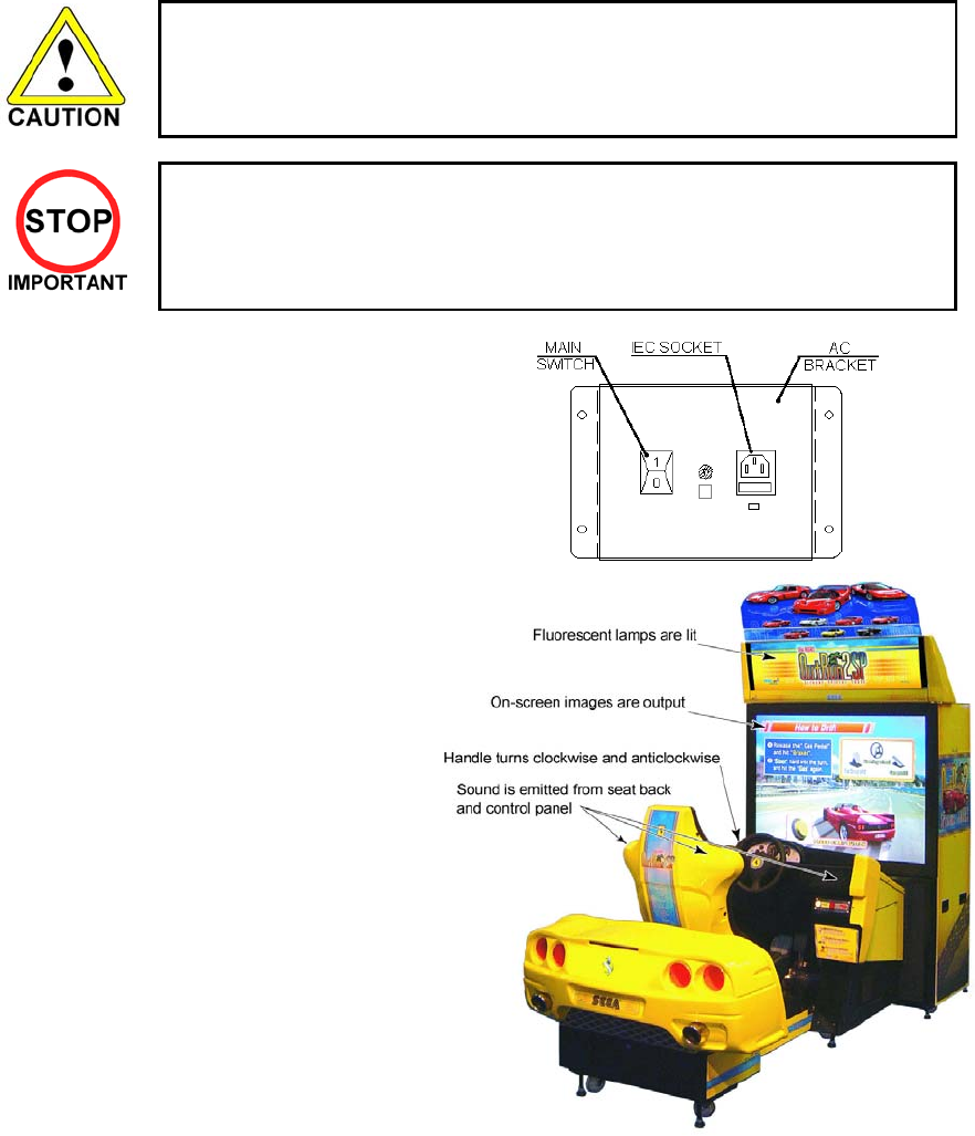
1. Insert the mains lead into the wall socket.
2. Insert the IEC plug into the IEC socket on
the AC bracket.
3. Switch on the power supply at the wall.
4. Switch on the mains switch on the AC
bracket.
When power is supplied, the BILLBOARD
fluorescent will light, and the screen will display
the system start up sequence. First, the
system will conduct an initialisation, during
which the steering wheel (Handle) rotates to
full left and right lock, before settling in its
central position. This allows the system to
check its datums. Do not touch the Handle
during this initialisation, as this may affect the
operation of the Handle during game play. If
the initialisation is disturbed, switch off the
machine, and leave for five minutes before
switching on again.
On completion, ADVERTISE mode will begin,
emitting sound from the speakers if this option
is set in TEST mode.
Turning off the power will not erase data such as full credits and score information, but data relating to
inserted coins less than the value of one credit, and the Bonus Adder, will be lost. If power is restored with
enough credits for play remaining, the game will begin automatically.
If two or more machines are linked for communication play, the NETWORK check is performed prior to
ADVERTISE mode. Should there be a problem with communication play, the check screen will remain
displayed. If an error is found, an error message is displayed for a while before NETWORK check is
resumed. A successful NETWORK check takes less than a minute.
25
3.15. Assembly Check
In the TEST MODE, ensure that the assembly has been made correctly and IC BD. is satisfactory (refer to
Section 9).
In the test mode, perform the following test:
3.15.1.Memory Test
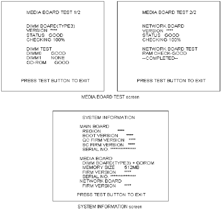
When "MEDIA BOARD TEST" is selected from the System Test Mode Menu Screen the Game Board
memory is automatically tested. If the display beside each memory reads "GOOD", the Game Board is
functioning correctly.
Also, when "SYSTEM INFORMATION" is selected, Main Board and Media Board data for the Game Board
are displayed. If data is displayed correctly, the Game Board is functioning correctly.
26
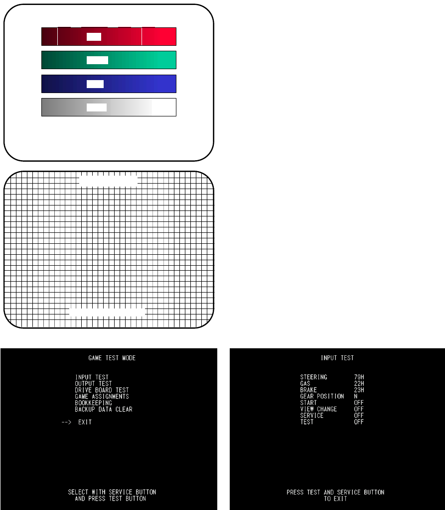
3.15.2.CRT Test
C.R.T TEST
PAGE 1/2
C.R.T. TEST 1/2
PRESS TEST BUTTON TO CONTINUE
RED
GREEN
BLUE
WHITE
In the TEST mode select CRT test to check the
screen is satisfactory.
Although the projector has been set up at the factory
before shipment, check to see if the screen needs
adjustment.
C.R.T. TEST 2/2
PRESS TEST BUTTON TO EXIT
Test the STEERING, GAS (ACCEL) and BRAKE controls to ensure that they are functioning properly and
that the parameters change smoothly as each input device is operated.
Display N, UP and DOWN using the GEAR POSITION. N displays that there is no control input. Verify that
both UP and DOWN display in sync with the position of the shift knob.
Press the START, CHANGE VIEW, SERVICE and TEST Buttons. If functioning correctly, each indicator will
switch from OFF to ON.
Press the SERVICE and TEST Buttons simultaneously to return to the Game Test Menu screen.
27
3.16. Moving The Machine
• When moving the machine, be sure to remove the plug from the power
supply. Moving the machine with the plug inserted can cause the power
cord to be damaged, resulting in a fire or electric shock.
• When moving the machine, retract the leg adjusters fully and ensure the
casters make contact with the floor. During movement pay careful attention
so that the casters or leg adjusters do not damage any other cabling laid on
the floor. Such damage could result in a fire or electric shock.
• This operation should only be carried out by QUALIFIED SERVICE
PERSONNEL.
• Use extreme care when moving the machine. Avoid using excessive force
when pushing any plastic parts.
• YOU MUST UNCOUPLE THE PTV FROM THE MAIN BODY BEFORE
MOVING THE MACHINE.
Do not push the PTV from the front or back; always push the PTV from the side.
28
3.17. Fuses
• Never touch places other than those specified. Touching places other than those
specified can cause electric shock and short circuit. Disconnect the machine from
the supply before attempting the replacement of any fuse.
• FUSES should only be replaced by QUALIFIED SERVICE PERSONNEL.
• FUSES should only be replaced with one of the same type and rating.
There are a number of fuses used on this machine to protect the user and the machine from damage. Only
replace the fuse once you have removed the cause of its failure. Detailed below is a list of the fuses used,
their location and if relevant PCB reference:
PART NUMBER LOCATION TYPE & DETAILS QTY
514-5078-5000 EP1302 (IEC INLET) 5x20 HRC SB 5000mA 1
514-5078-3150 838-13616 (F1&F2) 5x20 HRC SB 3150mA 2
514-5078-6300 838-13578 (F1) 5x20 HRC SB 6300mA 1
514-5078-6300 838-13142 (F101&F201) 5x20 HRC SB 6300mA 2
514-5078-6300 838-11856CE-02 5x20 HRC SB 6300mA 1
There are also fuses located on the Monitor PCB. Refer to the relevant Monitor manual supplied to
reference these fuses.
29
3.18. Maintenance
• Only Qualified Service Personnel must carry out maintenance.
• Ensure that the mains power is switch OFF and disconnected before attempting any
work.
• The CONTROL PANEL ASSEMBLY is heavy and may cause injury or damage to the
machine if dropped. Use an assistant when removing and replacing it.
• In order to prevent an electric shock and short circuit, be sure to turn power off before
performing work by touching the interior parts of the product.
• Be careful not to damage the wires. Damaged wires may cause electric shock or short
circuit or present a fire risk.
• Do not touch undesignated places. Touching places not designated can cause electric
shock or short circuit.
• This work should be performed by the site maintenance individual or other skilled
professional. Performing work by non-technical personnel can cause electric shock
hazard.
• Do not perform work other than those specified in this Manual in order to prevent
accidents during performing work and operation after performing work. Performing
work not specified in this Manual may require special training for this product. If
performing work other than those stated in this manual is required for repair, contact
the offices herein stated in this manual or where you purchased the product from and
ask for repair or inquire how to repair.
• Be very careful when soldering. Handling a soldering iron carelessly may result in a fire
or a burn.
• Be extremely careful when heating the heat-shrinkable tube. Failure to do so may
result in a fire or burns.
• Do not drop parts when removing them. Dropping parts may damage them or cause
sudden accidents.
• To prevent accidents, more than one person must perform these operations.
• Exercise extreme caution when handling the internal parts of the Control Panel. Watch
out for damage, warping and loss. The loss of just one piece may result in damage to
or lead to faulty operation of the entire unit.
• When securing the plastic-made parts, do not excessively fasten screws and nuts.
Failure to observe this may damage the parts and cause injury due to fragments
resulting from damage.
• Be sure to perform volume's move value setting in the Volume Setting in the Test
Mode after replacing or adjusting the Volume. (See 5.4.1)

30
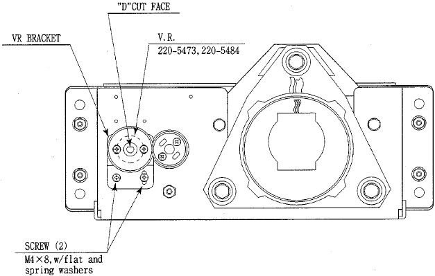
3.18.1.Handle Mecha
In the TEST MODE, if the steering wheel V.R. variations are not within the allowable limit, the V.R.
installation position requires adjustment or the V.R. needs replacement. Also be sure to apply grease every
3 months.
3.18.1.1.Access To The Handle Mecha’s VR
Access to the handle mecha’s VR can be made via removal of the bonnet cover.
The Bonnet Cover is attached using six fixings, three either side.
3.18.1.2.Replacing and Adjusting The Handle Mecha’s V.R.
• Never touch places other than those specified. Touching places other than those
specified can cause electric shock and short circuit.
• After the replacement or adjustment of the V.R. be sure to set the Centre of Steer in
the DRIVE BOARD TEST.
31
3.18.1.3.Adjusting the VR
Remove the Bonnet Cover as detailed above. Locate the V.R. on the rear surface of the HANDLE MECHA.
1. Using a screwdriver, loosen the 2 machine screws which secure the V.R. Bracket. Move the V.R.
Bracket so as to disengage the gears.
2. Gently rotate the V.R. until its value is within the range of the centring position. Position the steering
wheel in the centre position.
3. Mesh the gears together. Make sure that a correct amount of backlash is maintained between the
gears.
4. If the V.R. value is still not correct make fine adjustments by loosening the 2 machine screws on
the V.R. gear. Rotate the gear holder until the correct value is obtained.
5. The value should be adjusted such that with the steering wheel in the centre position the value
read during INPUT TEST shall be 80H±10H.
6. Re-set the centre of steer as described in the game test mode (output test).
3.18.1.4.Replacing the VR
Remove the Bonnet Cover as detailed above. Locate the V.R. on the rear surface of the HANDLE MECHA
1. Using a screwdriver, remove the 2 machine screws which secure the V.R. Bracket. Remove the
V.R. Bracket so as to disengage the gears.
2. Loosen the hexagon drive grub screws in the collar and gently slide off the V.R.
3. Reassemble is the reverse procedure of steps 1 and 2 above.
4. When complete you must readjust the V.R. in accordance with the paragraph above.
32
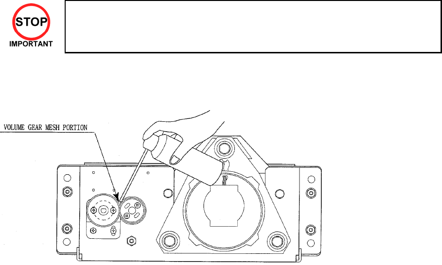
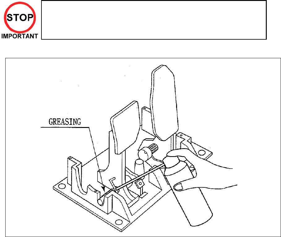
3.18.1.5.Greasing
• Be sure to use a good quality, synthetic lubricant. Using a mineral-based lubricant will
cause damage to the plastic parts.
• Do not apply lubricant to parts other than those specified. Doing so may cause damage
or deterioration of parts.
Apply lubricant to gear mesh portions once every 3 months.
33
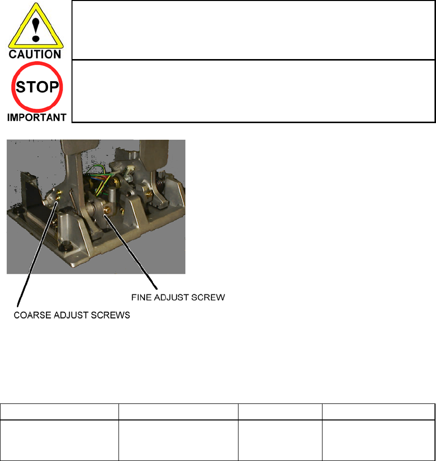
3.18.2.Accelerator & Brake
• Only Qualified Service Personnel must carry out maintenance. Ensure that the
mains power is switched OFF and disconnected before attempting any work.
In the TEST MODE, if the brake or accelerator V.R. variations are not within the allowable limit, the V.R.
installation position requires adjustment or the V.R. needs replacement. Also be sure to apply grease to all
moving parts every 3 months.
3.18.2.1.Removing the Accelerator & Brake.
1. Turn the POWER switch OFF
2. Remove a total of 4 screws securing the
covers over the ACCELERATOR & BRAKE
3. Fine adjustment of the V.R. values is
accomplished with just these covers
removed.
4. Coarse adjustment requires the
ACCELERATOR & BRAKE mounting bolts to
be removed. If this is necessary, remove the
bolts from the unit, but do not remove the unit
from the machine. Take extreme care when
operating the unit in this condition as damage
to other components can occur.
34
3.18.2.2.Adjusting the V.R.
• Never touch places other than those specified. Touching places other than
those specified can cause electric shock and short circuit.
• After the replacement or adjustment of the V.R. be sure to set the values in the
INPUT TEST.
1. Remove the cover panels as detailed above.
2. Fine Adjustment - By using a screwdriver loosen
the 2 machine screws that secure the V.R. arm.
Move the V.R. arm to adjust the V.R. value
within the relaxed range.
3. Coarse Adjustment - Remove the four hexagon
bolts detailed above and remove the side
covers of the Accelerator & Brake.
4. Loosen the two machine screws holding the
V.R. rack
5. Move the V.R. rack away so as to disengage
the V.R.
6. Gently rotate the V.R. until its value is within the
range of the centring position.
7. Mesh the gears together. Make sure that a
correct amount of backlash is maintained.
8. If the V.R. value is still not correct make fine
adjustments as detailed above.
The required values are:
GAS PEDAL: Under 30H ⇒ Over C0H
BRAKE PEDAL: Under 30H
(THE PEDAL
RELEASED)
⇒ Over C0H
(THE PEDAL
PRESSED)
35
3.18.2.3.Replacing the V.R.
1. Loosen and withdraw the V.R. rack as detailed above.
2. Using a hexagon key loosen the two grub screws holding the V.R. gear onto the V.R.
3. Remove the V.R. gear
4. Using a spanner remove the nut holding the V.R. in position.
5. Gently remove the V.R. and its wire harness.
6. Refit is the reverse of removal.
7. When complete you must readjust the V.R. in accordance with the paragraph above.
3.18.2.4.Greasing
• Be sure to use a good quality, synthetic lubricant. Using a mineral-based
lubricant will cause damage to the plastic parts.
• Do not apply lubricant to parts other than those specified. Doing so may cause
damage or deterioration of parts.
Apply lubricant to gear mesh portions once every 3 months.
36
3.18.3.Paddle Shift
• Maintenance must only be carried out by Qualified Service Personnel.
Ensure that the mains power is switch OFF and disconnected before
attempting any work.
In the TEST MODE, if the PADDLE SHIFT switches cannot be input correctly, the switch will need to be
replaced. Also be sure to apply grease to all moving parts every 3 months.
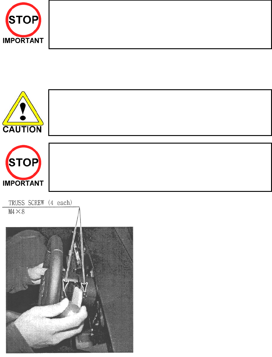
3.18.3.1.Replacing Paddle Shift Microswitches.
• Never touch places other than those specified. Touching places other than
those specified can cause electric shock and short circuit.
• After the replacement or adjustment of the microswitches check operation
using the INPUT TEST.
1. Turn the POWER switch OFF.
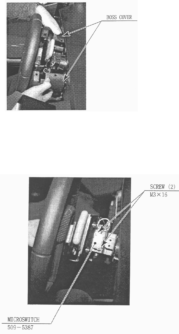
37
2. Remove the BOSS COVERS and retain
the 4 truss-head screws.
3. Disconnect the wiring to the microswitch.
4. Remove the microswitch and retain the screws.
5. Adjust the microswitch’s actuating arm so that it is not depressed until the paddle is moved in that
direction.
6. Refit is the reverse of removal.
7. Check the switch operation in the game test mode (input test).
38
3.18.4.Replacement Of Fluorescent And Other Lamps
• Never touch places other than those specified. Touching places other than those
specified can cause electric shock and short circuit. Disconnect the machine from
the supply before attempting the replacement of any lamp.
• Lamps should only be replaced by QUALIFIED SERVICE PERSONNEL.
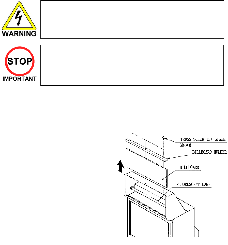
3.18.4.1.Fluorescent Lamp Replacement
Note: Use a step when performing this procedure.
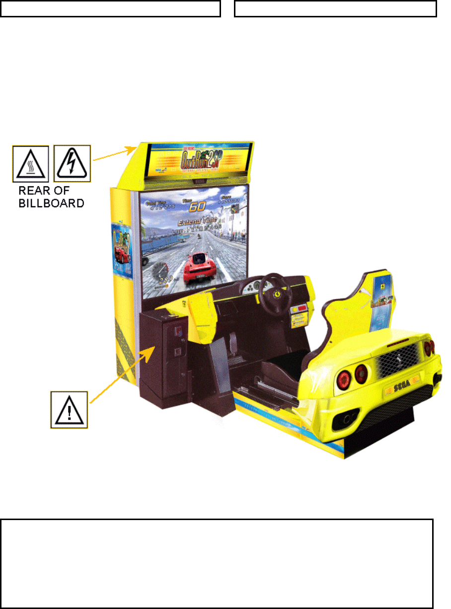
Remove the BILLBOARD HOLDER, slide the
BILLBOARD up, and replace the Fluorescent
Tube by carefully withdrawing it from the two
mounting clips.
Note: Billboard may differ from that shown..
39
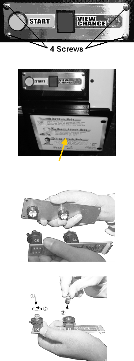
3.18.4.2.Start / View Change Bulb Replacement
1. Remove 4 screws holding front of Assy
Switch Plate
2. Remove the 5 screws holding the Multi
Language Play Instrustions Panel in place.
There are:
2 screws on the front.
2 screws underneath.
1 screw on top.
Access is now available to the rear of the
Assy Switch Plate through the front
aperture.
Multi-Language Play Instructions Panel
3. The lamp (bulb) is on the inner side of the
assembly. Turn the metal locking tag
anticlockwise (when viewing the rear of the
button) on each button and remove the
lamp housings from the assembly.
4. To remove the lamp, press it down and turn
anticlockwise.
40
3.18.4.3.Brake Light Bulb Replacement
Access to the rear brake lights is gained via the rear door.
Note: The machine uses 12V 2.2W wedge bulbs in 12 positions for brake light activation.
1. Slide the seat as forward as it will go to increase the access area to the rear door
2. Open the rear door by removing the 2 screws and using the keys.
3. For the outer lights, press the bulb holder legs together then remove the bulb holder and bulb.
4. For the inner lights, you can use the same procedure as above but, if access is too difficult, you will
have to remove the bulb holder bracket.
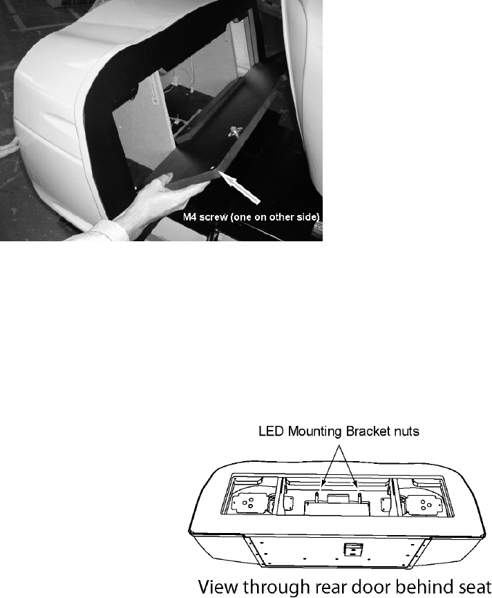
3.18.4.4.LED Strip Replacement
1. Remove rear door (see above).
2. Loosen the two LED mounting bracket nuts.
3. The bracket will now slide down if pressure is applied.
4. Completely remove the bracket.
5. Change the LED strip.
6. Replace the bracket and slide it upwards so that the LED strip is located square and central in the
rear moulding cut away.
7. Tighten the two LED mounting bracket nuts and replace the rear door.
41
3.18.5.Cleaning The Cabinet Surfaces
When the cabinet surfaces are badly soiled, remove stains with a soft cloth dipped in water or diluted (with
water) chemical detergent and squeezed dry. To avoid damaging surface finish, do not use such solvents
as thinner, benzine, etc. other than ethyl alcohol, or abrasives, bleaching agent and chemical dustcloth.
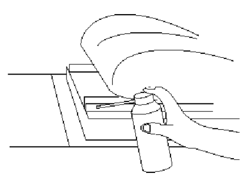
3.18.6.Seat (Greasing To Seat Rail Portion)
Move the Seat to the rearmost position
and apply spray greasing to the portion
shown at the right once every 3 months by
using NOK KLUBER L60 or GREASE
MATE SEGA PART No. 090-0066.
After greasing, move the Seat a few times
forward and backward so as to allow the
grease to be applied all over uniformly. Be
sure to wipe grease which attaches to the
surfaces of the PROTECT RUBBER on
the Seat Rail, or any excess grease.
42
3.19. Troubleshooting
• Only QUALIFIED SERVICE PERSONNEL should carry out these
procedures
3.19.1.Troubleshooting (When No Error Message Is Shown)
• In order to prevent electric shock and short circuit, be sure to turn power off before
performing work. ·
• Be careful so as not to damage wirings. Damaged wiring can cause electric shock or
short circuit.·
• After removing the cause of the functioning of the Circuit Protector, reinstate the
Circuit Protector. Depending on the cause of the functioning, using the Circuit
Protector as is without removing the cause can cause generation of heat and fire
hazard.·
• In the event that a problem cannot be resolved by employing the procedures listed in
this Manual, be sure to request service from the office shown on this Manual or the
dealer from whom the product was originally purchased. Attempts to employ
procedures other than those specified in this Manual can cause electrical shock,
shorting, or fire.
• In the event of a problem that is not described here, be sure to contact the office
shown on this Manual or the dealer from whom the product was originally
purchased. Careless attempts at repair can result in electrical shock, shorting, or
fire.
If a problem occurs, first check to make sure that the wiring connectors are properly connected.
PROBLEM CAUSE COUNTER MEASURES
The power is not ON. Firmly insert the plug into the outlet.
Incorrect power source/voltage. Make sure that the power
supply/voltage are correct.
When the main SW is
turned ON, the machine
is not activated.
The fuse of the connect board was blown
out due to momentary overcurrent.
After eliminating the cause of
overload, replace the specified rating
fuse.
Connector connection fault. Check connector connections
between the Cabinet and the FL box.
Fluorescent lamp inside
FL box doesn't light up.
Fluorescent lamp and Glow lamp need
replacement.
Replace the fluorescent lamp and the
glow lamp (See Section 3.18.4.1)
Connector connection fault. Check connector connections
between the Cabinet and the lamp.
Lamps in control panel or
brake lights do not light
up. Lamp needs replacement. Replace the lamp (See Section
3.18.4.2)

43
PROBLEM CAUSE COUNTER MEASURES
Sound volume adjustment is not
correct.
Adjust the sound adjustment volume . (See
Section 5.2)
Faulty connections for various
connectors.
Check the connections for the game board,
amp, speakers and Volume connectors.
Sound is not emitted.
Malfunctioning BD, Amp. and
Speaker.
Perform SOUND TEST. (See 5.3.1.4)
Faulty connections for the visual
signal connector or the monitor
power connector.
Check the connections for the monitor and
game board connectors.
Sounds are emitted and
the lamps are lit, but the
screen is black.
Broken monitor. Contact the company from whom the unit
was purchased.
Faulty connection for the visual signal
connector.
Check the visual signal connector
connection and make sure it is secured
properly.
Colors on the monitor
screen are strange.
Screen adjustment is not appropriate. Make adjustment appropriately. (See
Monitor Manual)
The on-screen image
sways and/or shrinks.
The power source and voltage are no
correct.
Make sure that the power supply and
voltage are correct.
Check the connection for the I/O Board and
Cabinet connector.
Does not accept input
from any switch or
volume.
Faulty connector connections.
Check the power for the I/O Board.
Faulty connector connections. Check the connections for the connectors in
the Control Panel and between the Control
Panel and the Cabinet.
Does not accept input
from the PaddleShift.
Broken Microswitch. Replace the Microswitch
Incomplete power on check. Power on and verify that the power on
check completes properly. (See 3.14)
Deviation of the volume value. Adjust the volume value in the Test Mode.
Volume gear engagement fault. Adjust the engagement of the gear. (See
Section 3.18.1.3)
Volume malfunctioning. Replace the volume. (See 3.18.1.4)
STEERING (Servomotor)
response is incorrect.
Detached wires. Check for faulty wire connections around
moving parts.
When replacing wires, secure them so that
they do not touch any moving parts.
BASE SHAKER does not
react.
Incorrect volume adjustment. Adjust the volume setting on the VTS
board. (See 5.2)

44
PROBLEM CAUSE COUNTER MEASURES
Failure of power-on checking
procedure.
Reconnect the power and complete a
power-on checking procedure. (See
Section 3.14)
Faulty connector connections. Check the connections for the connectors
between the Game Board and
Servodriver and between the Servodriver
and the Servomotor.
Thermal element in the Servodriver
is operating.
Occurs when the internal temperature
reaches 70°C (158°F) and corrects
automatically when the unit cools.
No response from Steering
(Servomotor).
Momentary overload caused a fuse
on the Servodriver to blow.
Contact the company from whom the unit
was purchased.
Steering (Servomotor) is
week in its force feedback.
Aging of the force feedback
mechanism.
Reset in the Test Mode. ( See 5.4.1)
Incorrect volume setting. Adjust the volume value in the Test
Mode. (See 3.18.2.2)
Faulty Volume attachment or
adjust gear alignment.
Adjust the volume attachment and verify
in Test Mode. (See Section 3.18.2.2)
Faulty connector connection. Check the connections for the Accel and
Brake connectors and the connectors
between the Accel, Brake and Cabinet.
Unsatisfactory Accel and
Brake operation.
Failure of the volume. Replace the volume. (See 3.18.2.3)
Start button and Change
View button input does not
work and they do not flash.
Faulty connector connections. Check the connections for the connectors
between the I/O Board, the Cabinet and
the Control Panel and those inside the
Control Panel.
Unverified settings or operation. The Start button only flashes when Free
Play is set. Check the operation in Test
Mode.
(See Section 5.4.1)
Start button and Change
View button input works,
but they do not flash.
The lamp is burnt out. Replace the lamp.
Network play is wrongly set. Reset correctly. (See Section 3.20.8)
Communication cables are wrongly
connected.
Communication cables are
disconnected.
Reconnect the cables.
(See Section 3.20.8)
Failure of the network play.
Damage of communication cables. Reconnect cables correctly. (See Section
3.20.8)
Replace the cables. Contact the company
from whom the unit was purchased.
45
3.20. Game Board
• Turn off the mains power and remove the power cord before opening the machine.
• The GAME BOARD should not require any work to be carried out upon it. All
settings and tests can be achieved without access to the GAME BOARD.
• All work to be carried out by QUALIFIED SERVICE PERSONNEL.
3.20.1.Removing The Game Board Assembly
1. Turn power off
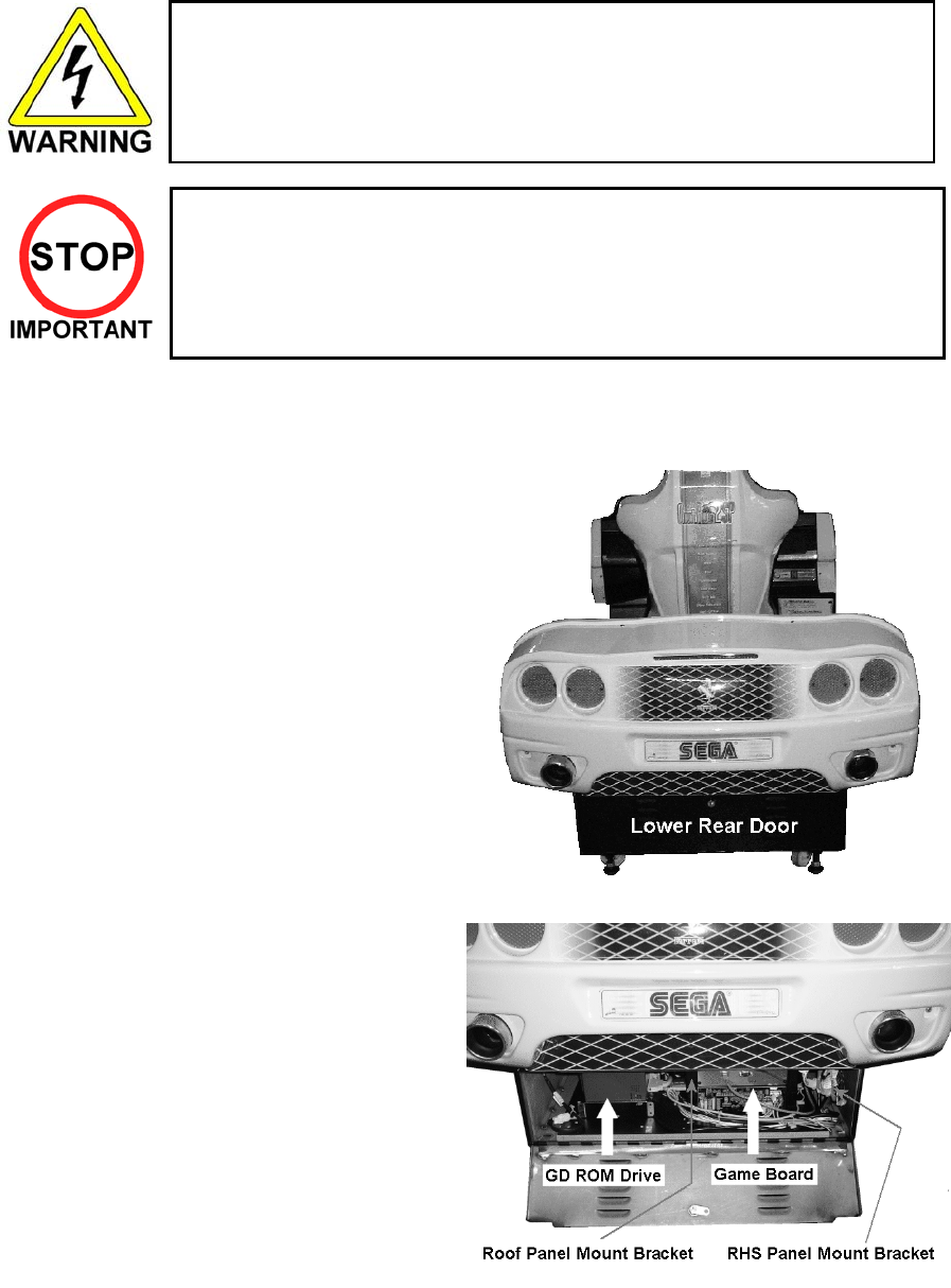
2. The lower rear door is located at the back
of the main cabinet underneath the fairing.
3. Remove 1 truss screw located next to the lower rear door lock
4. Disconnect the 5 plug breaks on the panel
mount bracket on the right hand side.
5. Disconnect 2 plug breaks from the panel
mount bracket situated in the roof of the
base box (to the left of the game board).
6. Uncouple the fan loom from the lower rear door
7. Disconnect the LAN cable from the game board
46
8. Disconnect he USB cable from the game board
9. Remove the M6 bolt holding the game board in place. It is situated on the front edge of the board.
10. Slowly remove the game board ensuring that no wires are trapped or still connected.
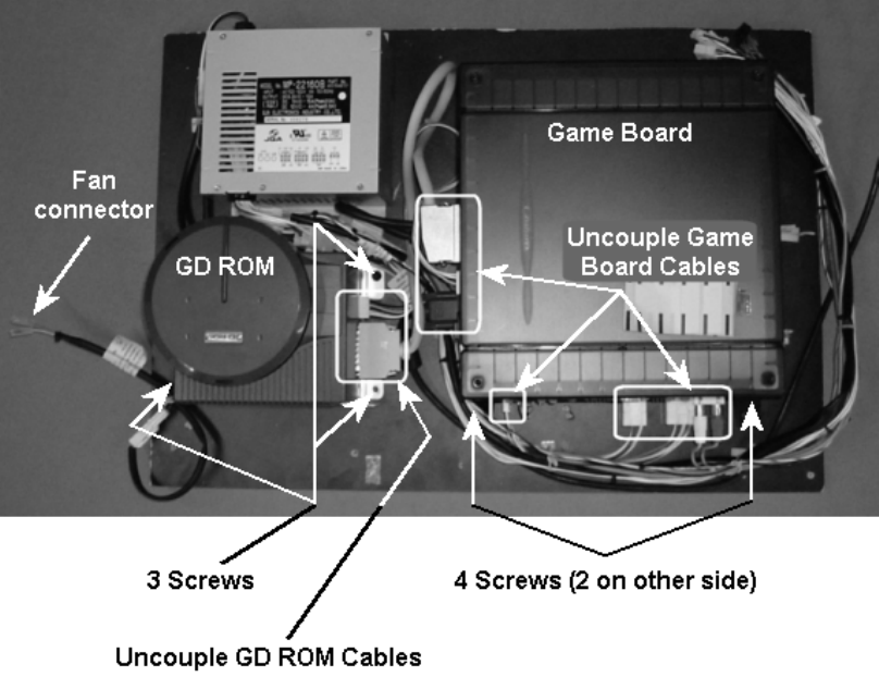
3.20.2.Removing The GD-ROM Drive
1. Before you can remove the GD ROM Drive, you must remove the Game Board Assembly (see 3.20.1).
2. Remove the GD cable and power cable from the GD ROM Drive.
3. Remove the 3 screws fixing the drive to the assembly board.
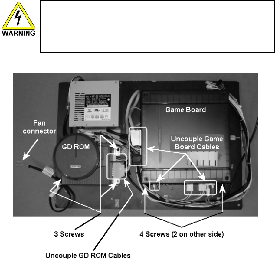
47
3.20.3.Removing The Game Board
• When returning the game board for replacement or repair, make sure that the
connectors are attached correctly. Incorrect connections can lead to accidents such as
electric shock, short circuits, and/or fire.
• When plugging in connectors, pay close attention to the direction of the connection.
The connectors are designed to be connected in a specific direction. Attempting to plug
in a connector by applying excessive force may damage the connector or its terminal
clasp, possibly resulting in electric shock, short circuits, and/or fire.
1. Before you can remove the GD ROM Drive, you must remove the Game Board Assembly (see 3.20.1).
2. Remove all the all cables connected to the Game Board.
3. Remove the 4 screws fixing the drive to the assembly board.
48
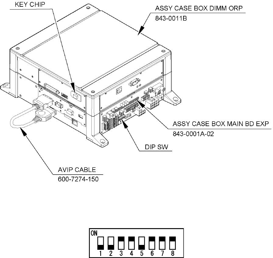
3.20.4.Composition of the Game Board
Once the Chihiro Board has the Key Chip inserted, it is this product's specialized Game Board.
ASSY CASE BOX ORP EXP 843-0011D-02
DIP SW SETTING
Use this product with the DIP SW settings shown in the figure below.
49
3.20.4.1.Replacing The Main Board Battery
• To prevent overheating, explosion, or fire:
• Do not recharge, disassemble, heat, incinerate, or short the battery.
• Do not allow the battery to come into direct contact with metallic objects or
other batteries.
• To preserve or to dispose of the battery, wrap it in tape or other insulating
material.
• Follow local regulations when disposing of the battery.
Improper disposal can damage the environment.
• To avoid risk of malfunction and damage:
• Make sure the positive and negative ends are aligned correctly.
• Use only batteries approved for use with this unit.
• If an error appears indicating that the battery power is very low within the first
year of use, it is usually an indication of a problem or abnormality with something
other than the battery. Be sure to inspect the board that the battery is connected
to.
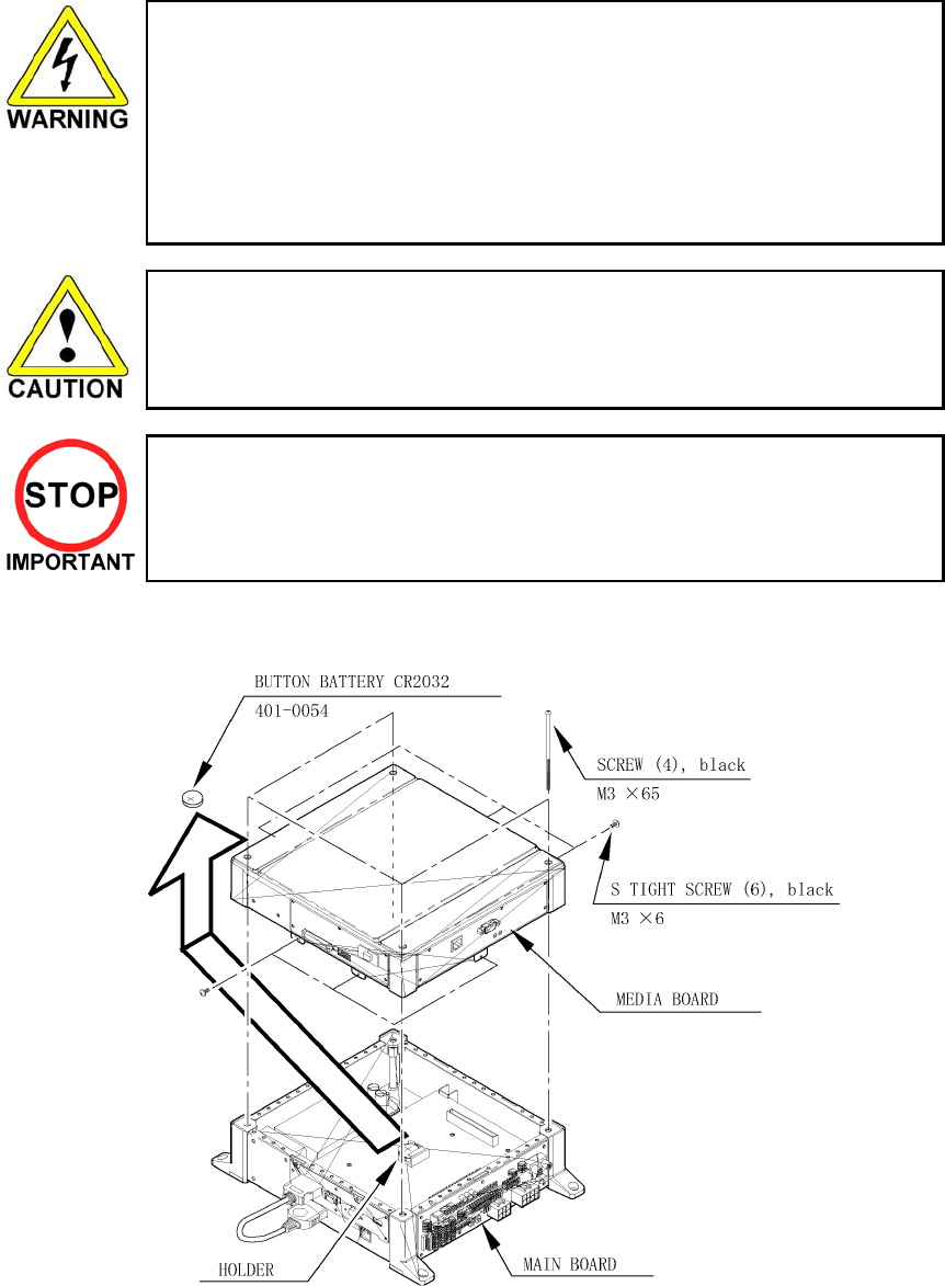
There is a Media Board Button Battery underneath the Media Board.
• Carefully remove the battery from its holder.
• Insert a new battery into the holder with the "+" terminal facing up.

50
3.20.4.2.Replacing The Media Board Battery Pack
Prohibitions and Cautions to Handle the Battery Pack
• Be careful when handling the battery pack.
• We bear no responsibility for problems caused by handling clearly contrary to the content of this
manual.
• Do not disassemble the battery pack and the batteries.
• If you should fail to observe this instruction, the internal wires and/or protective
devices may be damaged; as a result the safety system may not function when
discharging and recharging, eventually causing an overheating, fire and
explosion. If you should disassemble the batteries, the generated gases may
harm your throat and the negative plate may overheat and make a fire.
• Do not make an external short circuit of the battery pack and the batteries.
If you should fail to observe this instruction, the batteries may overheat, make a
fire, and explode.
• Do not fire the battery pack and the batteries.
If you should fail to observe this instruction, the batteries may make a fire and
explode.
• Do not leave the battery pack and the batteries nearby the heat source (fire or
heater) or under the intense direct sunlight and flaming sun.
If you should fail to observe this instruction, the batteries may reduce the service
life and in the worst case may overheat, make a fire, and explode.
• Do not leave the battery pack and the batteries in water or seawater. Also do not
apply water or seawater onto the battery pack and the batteries. If you should fail
to observe this instruction, the internal wires and/or protective devices may be
damaged; as a result the safety system may not function when discharging and
recharging, eventually causing an overheating, fire and explosion. Also water
may be electrolyzed into oxygen and hydrogen, and eventually the battery's
sealed section may be corroded and the internal liquid may leak.
• Do not solder on the battery pack's terminals.
If you should fail to observe this instruction, the armour may be heated and
melted or the internal wires may be damaged, eventually causing an overheating,
fire and explosion. Also, when the battery's temperature reaches to 100Ž or
more, the battery may leak its internal liquid due to destruction of its plastic parts
(gasket, separator, etc.), or may overheat, make a fire, or explode due to internal
short-circuit.
• Do not insert or connect the battery in a reversal polarity.
If you should fail to observe this instruction, the battery may be externally short-
circuited and eventually overheat, make a fire, or explode, depending on the
device you connect with.

51
• Do not tightly seal the battery pack when installing it onto an external device.
• Flammable gas is generated from the battery when its safety mechanism has
functioned. If you should fail to observe the above-described instruction, sparks
from motors, switches, etc. may cause the gas to fire. Therefore, install the
battery pack so that the gas can be quickly released from the external device.
• Do not use the battery pack for the device/usage other than this game system.
If you should fail to observe this instruction, the battery and/or the device may be
damaged due to non-applicable specifications.
• Do not strike a nail in, hammer, step on, or apply any other forms of pressures
and shocks on, the battery.
If you should fail to observe this instruction, the battery may be deformed. As a
result, the battery may burst at its sealed sections to leak the internal liquid, or
may be short-circuited internally to overheat, make a fire, and explode.
• Do not use a battery charger because any battery charger is not usable for this
battery pack.
If you should fail to observe this instruction, the gas may be suddenly generated
in the battery and eventually the battery may overheat, make a fire or explode.
• If the battery in use or in keeping shows an abnormal indication (deformation,
change of colour, bursting of the armour cover, etc.), immediately stop using or
keeping it. If it leaks and smells abnormally, immediately keep it away from fire
and put it in a safety box.
• If the liquid leaks from the battery and gets in your eyes, do not rub your eyes but
immediately wash them with clean water (city water etc.); and consult a medical
doctor for a treatment. If you should fail to observe this instruction, the liquid may
harm your eyes.
• The battery pack armour (a polyvinyl chloride tube) may be damaged or
deformed by external force or heat. When transporting the battery pack or
replacing it with a new one, therefore, be careful not to drop or excessively shock
it. Do not continue to use any damaged or deformed battery pack. If you should
fail to observe this instruction, the battery may overheat, make a fore, or explode.
• The battery pack contains a printed circuit board (PCB) for protective circuitry. It
may be destroyed by the static electricity. When handling or servicing the battery
pack, therefore, take preventive measures against the static electricity.
• If your battery pack has shown destruction of a protective circuitry PCB, do not
continue to use it. If you should fail to observe this instruction, the battery may
overheat, make a fore, or explode.
• When wiring the battery pack to a device, be careful not to apply excessive force
onto the connectors and lead wires. The battery may overheat, make a fire, or
explode if the connectors and lead wires are damaged.
• When discarding the battery pack at a disposal specialist, be sure to cover the
terminals with tape or some other covering and avoid damage when packing.
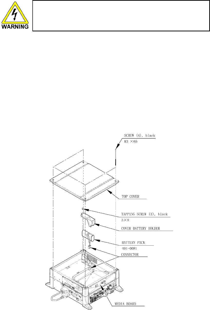
52
• Do not do away with the used battery packs carelessly because they may
contaminate the environment. Be sure to dispose of the used battery packs in
accordance with the laws/regulations of your country.
If the GD-ROM read time becomes excessively long, it is likely that the Media Board battery pack life if
running low.
No battery pack charger is available.
Follow the procedure to replace the battery pack:
1. Remove 4 screws from the upper face of the board.
2. Remove the top cover.
3. Remove 1 tapping screw and remove the cover battery holder.
4. Disconnect the connector at the end of the wire coming out of the battery pack. Remove by
pressing the projection on the connector and pulling.
5. Securely connect the new battery pack.
6. Attach the cover battery holder and top cover.
Submit the used battery packs to an industrial waste disposal plant. Thus they must be disposed according
to the local laws and the regulations in your country.

53
3.20.5.Shipping The Game Board
Replacement or repair of the Game Board (Chihiro) for this product should be undertaken
at the appropriate repair centre. Be sure to follow the specifications below when requesting
repairs/sending the board to the repair centre. Not following the specifications may result in
the board not being accepted or in extra charges being made.
• Put the game board in the carton box as is. Do not carry out any disassembly or part
removal other than that specified.
• Follow the procedure and instructions regarding direction below when placing the
Game Board in the carton box.
• When packing the game board with the Media Board attached, do not remove the Key
Chip.
• When packing the game board with the Media Board detached, be sure to include the
AVIP Cable.
• When packing, attach the accessory stickers in the specified places on the Game
Board and carton box.
INSTRUCTIONS
1. Wrap the Chihiro Board in a plastic bag.
2. Place it on top of the bottom surface cushioning material. Turn the Filter Board to face the side with
the three honeycomb buffers. Packing it in the opposite direction may cause damage to the Filter
Board.
3. Insert corrugated cardboard into the space between the lateral honeycomb buffers of the bottom
surface cushioning material and stow the AVIP cable inside.
4. Place the Chihiro Board wrapped in the bottom surface cushioning material into the carton box. Use
the handles on the bottom surface cushioning material.
5. Place the upper surface cushioning material on top of the Chihiro Board. Be sure to align it in the
right direction, as it will not fit otherwise.
6. Close the top of the carton box and seal it tightly with adhesive tape.
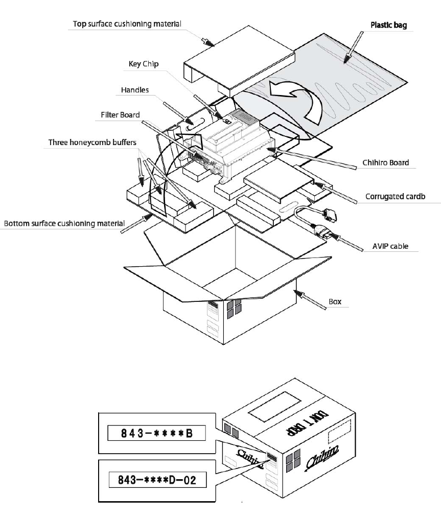
54
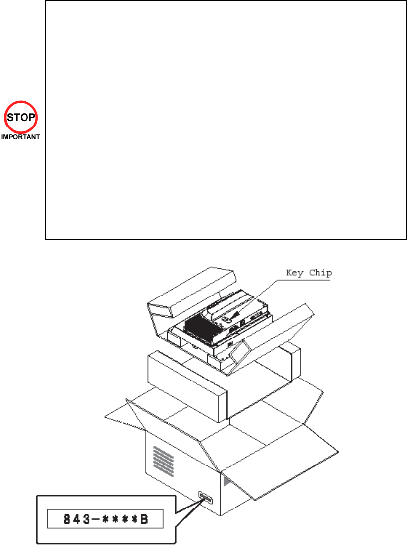
55
3.20.6. Shipping The Media Board
When sending the Media Board for repairs, follow the specifications below and
request repairs or send the Board to your retailer/the repair centre.
Not following the specifications may result in the board not being accepted or in extra
charges being made. Also, mistaken handling can damage or result in loss of parts.
• Be sure to use the special purpose carton box included with this product.
• Do not remove the Key Chip. Send the board with the Key Chip attached.
• Undo the 10 screws holding the Media Board to the Main Board and pack the
Media Board. Do not carry out any disassembly or part removal other than that
specified in this manual.
• Pack the Media Board in the special purpose carton box as shown in the
explanatory diagram.
• The packing material in the carton box has a shock absorbing function. Be sure
to use it when packing. Do not bend or fold the material in a direction other than
that shown on the diagram.
• Do not pack any wires, cables, or screws together with the Board.
• Be sure to attach the special purpose carton box accessory sticker
"843-ÅÅÅÅB."
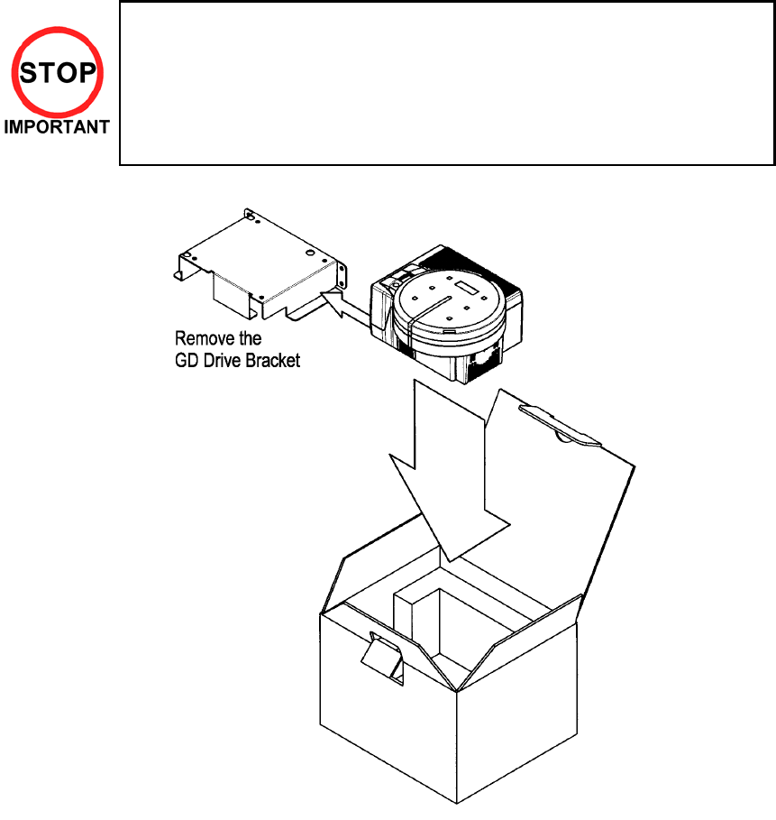
56
3.20.7.Shipping The GD-ROM Drive
• When returning the GD-ROM DRIVE for repair or replacement, be sure to
package it in the original card transit box - THERE ARE NO USER-
SERVICEABLE PARTS INSIDE.
• Ensure the GD-ROM Disk is removed and the GD-ROM Drive Lid is replaced on
the unit, with fixing screw, before packaging. Also, remove the GD-ROM Drive
Bracket and store with the four screws for reuse.
• Failure to return the GD-ROM DRIVE in this manner may invalidate the warranty.
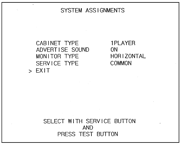
57
3.20.8.Machine Set Up
During linked play, if the test mode is not finished within three minutes on all linked machines, the
NETWORK CHECK cannot be performed, causing a NETWORK ERROR.
First, set up each linked machine to meet the requirements of communication play. If the settings are
incorrect, communication play is not possible.
58
3.20.8.1.Network Play
Up to 4 machines can be linked for network play. Properly connected network cables and correct network
play settings are required for network play.
3.20.8.1.1.Precautions Regarding Network Play Setup
• Before starting to work, ensure that the Power SW is OFF. Failure to observe this
can cause electric shock or short circuit.
• Use care so as not to damage wirings. Damaged wiring can cause electric shock
or short circuit.
• Do not touch undesignated places. Touching places not designated can cause
electric shock or short circuit.
• This work should be performed by the site maintenance individual or other skilled
professional. Performing work by non-technical personnel can cause electric shock
hazard.
• When linking a number of machines, be sure to supply sufficient power for the
corresponding number of machines. Be sure to secure per machine current as
stated in this manual. Failure to observe this can cause a fire and an electric shock
accident.
• Due to the length of the network cable, the distance in between the machines is
limited. However, to avoid accidents, be sure to secure space in excess of 70 cm
between the machines.
• To perform work safely and avoid serious accident such as the cabinet's falling
down, do not perform work in places where step-like grade differences, a ditch, or
slope exist.
• To perform work safely, be sure to secure the space corresponding to number of
machines to be linked. Failure to observe this can cause accident.
• To avoid accidents, use a cable cover that will not cause patrons to trip when laying
network cables in areas of heavy foot traffic.
• To prevent accidents and acts of vandalism, cover the network cables with the
strongest cover possible.
• Network play is not possible between game machines with different cabinet types.
When connecting several games machines together, make sure that a sufficient amount of electrical power
is available for each machine. Plan on providing 15A for each machine in 100-120V locations, and 7A in
220-240V locations.
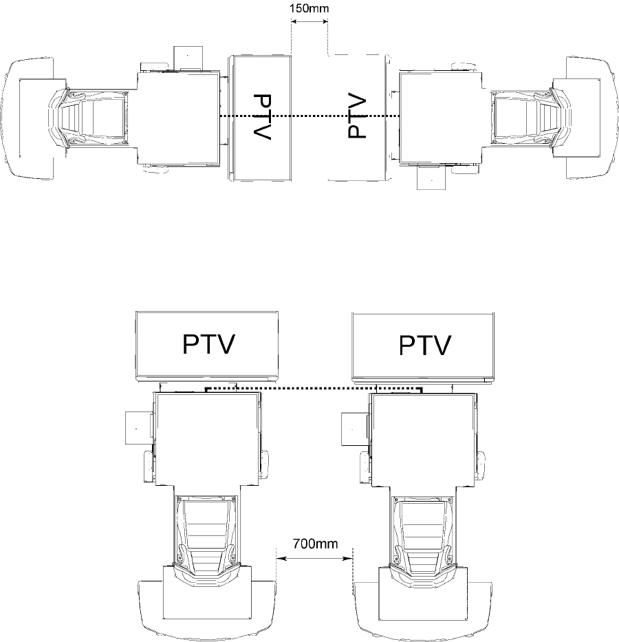
59
3.20.8.1.1.1.Spacing of Game Machines
Leave at least 15 cm of space between game machines when they are positioned facing each other.
Leave at least 70 cm of space between game machines when they are positioned adjacent to each other.
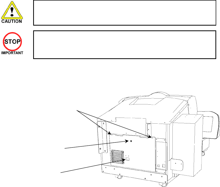
60
3.20.8.1.2.Connecting Network Cables
To enable network play, the hubs inside each of the game machines involved must be connected with
network (LAN) cables. Connect the hub inside one of the machines to the hub in the other machine using
LAN cables. There is no need to connect the other machines to each other in any other way.
Do not connect LAN cables between twin machines when they are not used for network play.
1. Turn off the power and unplug the power cord from the outlet. Place the power cord so as not to
damage it while working.
• Use extreme care when moving the machine. Avoid using excessive force
when pushing any plastic parts.
• YOU MUST UNCOUPLE THE PTV FROM THE MAIN BODY BEFORE
MOVING THE MACHINE.
2. Using the illustrations on the previous page as reference, move the machines so that they arranged
into the correct configuration. Leave enough space to perform the rest of the operations in this
procedure.
3. Referring the to diagram below, undo the two screws and use the key to open the door.
4. Route the LAN cable (part of the Installation Kit ORP-INST-D) through the hole in the door and
attach it to any of the free connections on the hub.
Note: The PTV harnesses also use this hole.
5. Repeat steps 3 and 4 to connect the other end of the LAN cable to the second machine.
6. Replace the door.
7. Once the machines have been linked for network play, line them up. Leave as much space as
possible between the machines.
8. Reconnect the PTV to the Main Assembly. (See 3.10)
9. Secure all leg adjustors on each machine. (See 3.12)
10. Connect the power cord.
LAN cable hole
Screws
Lock

61
3.20.8.1.3.Network Play Settings
Each of the linked machines must be set up for network play. If the machines are not set up correctly,
network play will not be possible.
3.20.8.1.3.1.How To Set Up A Machine For Network Play
1. Turn off the power on each machine to be used in network play.
2. Enter Test mode on each machine. (See Section 5.1)
3. Select GAME TEST MODE and press the TEST Button. The machine will enter Game Test mode
and the screen will display the Game Test menu. (See Section 5.4)
4. Select NETWORK SETTINGS from the Game Test menu and press the TEST Button. The Network
Settings screen will appear. Network settings are carried out on this screen.
5. Set the LINK NUM setting on the Network Settings screen to the number of game machines linked
for network play.
6. Set up the GROUP setting on the Network Settings screen. The GROUP setting is used to divide
the machines linked for network play into groups. For example, a network of 4 machines could be
divided into 2 groups of 2 machines.
7. Set the NUMBER setting on the Network Settings screen so that each machine within a group has
a different number. Make sure that one machine in each group is set to "1".
8. Exit Test mode on each machine. Be sure to choose EXIT from the System Test Menu to exit Test
mode properly.
9. Once each machine has exited Test mode and gone through initialization, it will begin a network
test. During the network test, the monitor will display a network test screen.
10. If there are no problems with network play settings or cable connections, the machine will enter
Advertising mode.
11. If the advertising screen appears after the network test is finished, network settings are complete.
12. The network test should last roughly 20 to 30 seconds. If the network test screen fails to disappear,
the problem is most likely due to one of the following: incorrect settings, an improperly connected
LAN cable, a faulty LAN cable connection, or a severed wire.
NETWORK SETTING
LINK NUM 2(2•`4)
GROUP A(A•`Z)
NUMBER 2(1•`4)
-> EXIT
SELECT WITH SERVICE BUTTON
AND PRESS TEST BUTTON

62
3.20.8.1.4.General Precautions Regarding Network Play
• When setting up machines for network play, settings such as the game's difficulty
level will be derived from the machine whose "NUMBER" is set to "1". If settings on
machine "1" are changed, the other machines will have their settings changed
accordingly. On machines other than "1", settings derived from machine "1" will not
be displayed on screen and cannot be changed.
• Should a network connection fail during network play, gameplay will be suspended
and the Network Error Screen will be displayed.
• If one of the units attached for network play enters Test Mode, the other unit will
display the same Test Mode Screen.
• Even when units are connected for network play, each seat, each game may be
given different cost settings. Incorrect cost settings may cause budget balancing
problems.
Note that when 2 or more machines are linked together for network play, some functions are different than
for stand-alone machines.
Whenever Test mode is used on a machine linked for network play, all machines connected to the network
will display the network test screen. When patrons are engaged in network play, do not enter Test mode on
any of the machines in the network, even if the machine is not in use.
However, machines whose GROUP setting is different from that of the machine entering Test mode will not
be affected.
63
3.21. Periodic Check and Inspection
The items listed below require periodic check and maintenance to retain the performance of the machine
and ensure safe operation:
• Be sure to check annually to see if the power cords are damaged. The plug is
securely inserted and that there is no dust in the interior of the machine or between
the socket and the power cord. Using the product in an unclean condition may
cause a fire or electric shock.
• Periodic checks should only be carried out by QUALIFIED SERVICE PERSONNEL.
DESCRIPTION WHAT TO CHECK INTERVAL
HANDLE MECHA Check the V.R. value
Check adjust gear engagement
Greasing of gears
Monthly
Every 3 months
Every 3 months
ACCELERATOR & BRAKE Check the V.R. value
Check adjust gear engagement
Greasing of gears
Monthly
Every 3 months
Every 3 months
SHIFT LEVER Check SW
Greasing
Monthly
Every 3 months
MONITOR / PROJECTOR Clean screen (do not use water jet)
Check adjustment
Weekly
Monthly
SEAT Rail greasing Monthly
GAME BD Memory Test
Game Assignments
Monthly
Monthly
INTERIOR Clean (do not use water jet) Annually
POWER SUPPLY CORD Check condition Annually
CABINET SURFACE Clean (do not use water jet) As required
CONTROL PANEL Lamp operation
Check switch operation
Monthly
Monthly
COIN MECHANISM Check SW (If Fitted) Monthly
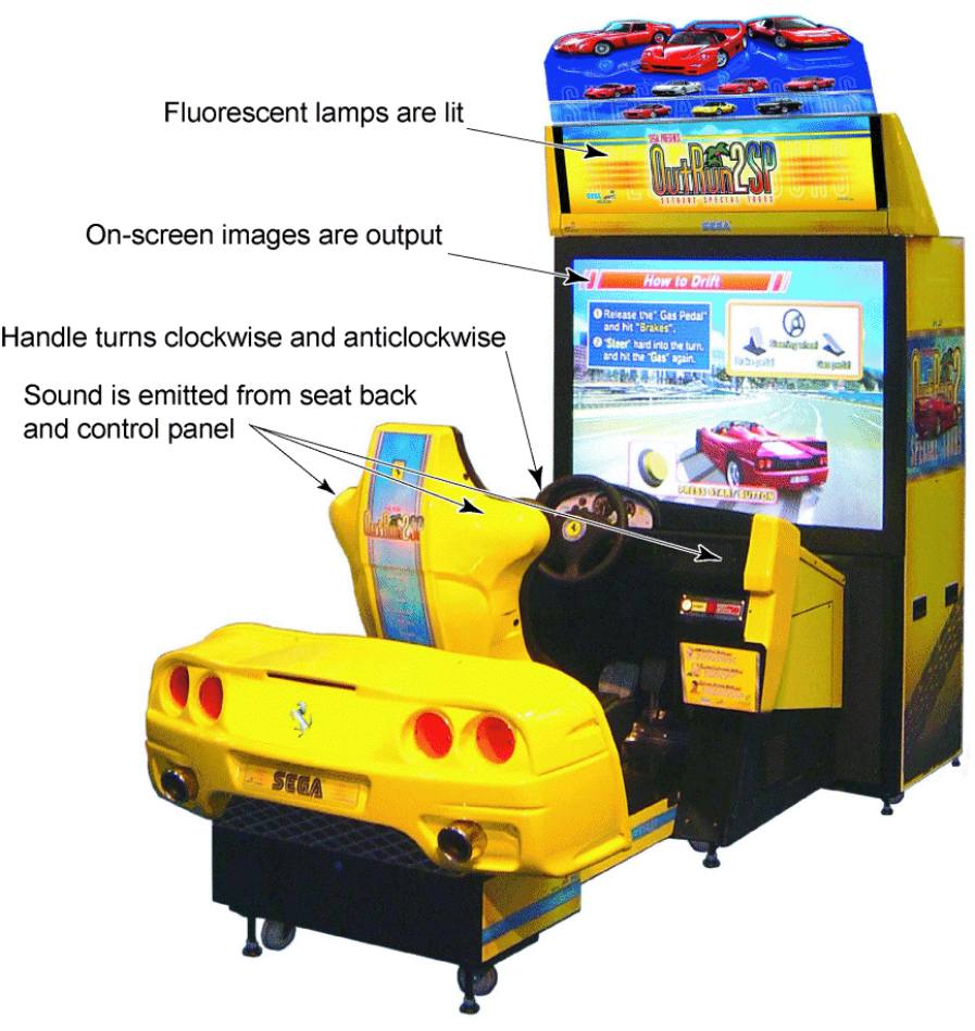
64
4. GAME DESCRIPTION
The following section details the game when it is functioning correctly. If any details are different, there may
be a fault. Identify and eliminate the fault to ensure satisfactory operation.
When power is connected, the fluorescent lamp in the FL box is always on. When in an advertising state,
the screen displays demonstration pictures and ranking data. Sounds are heard from the speakers on the
right and left of the seat. The advertising sounds are not heard if you have set this function to off (disabled).
The start button and the change view button on the control panel are illuminated.
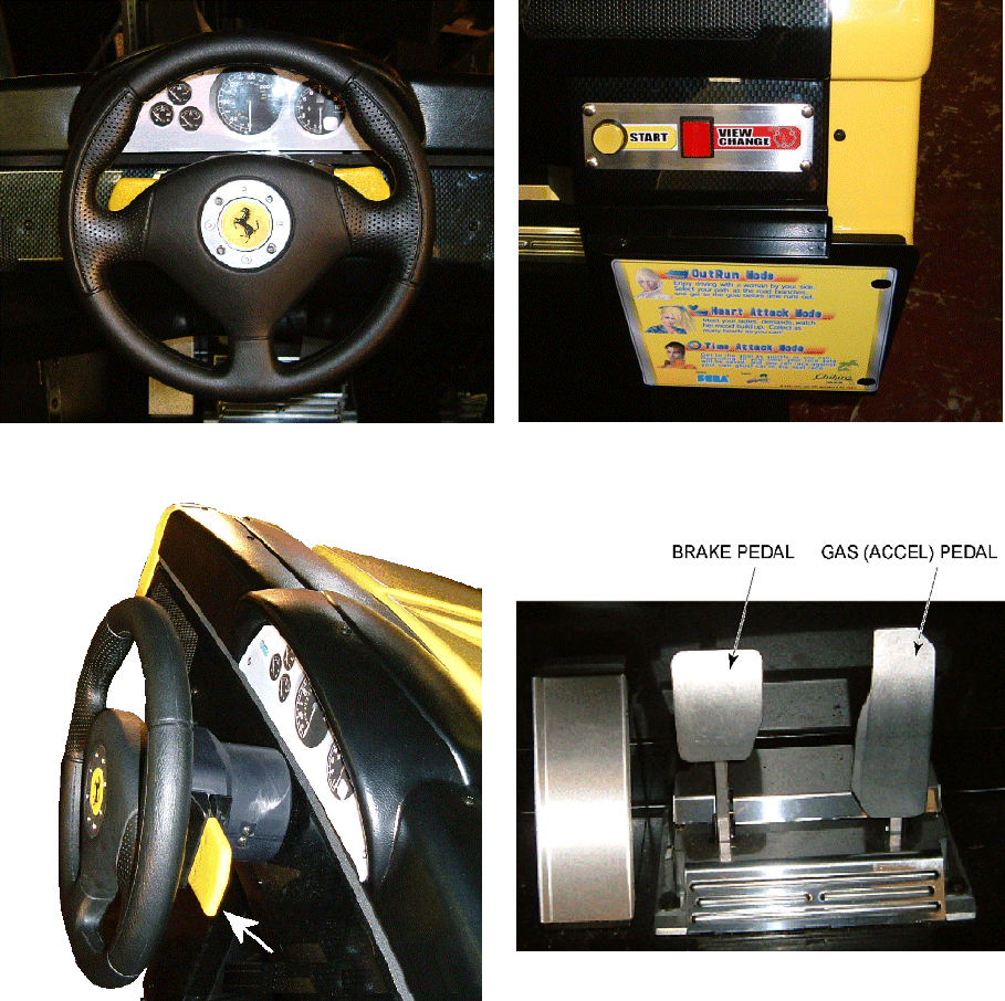
65
4.1. Basic Controls
Steering Wheel START and VIEW CHANGE Buttons
Paddle Shifter Pedals
Insert a coin and press the Start Button to begin a game.
Choose your car, game mode, background music, and other options. View choices with the Steering
Wheel, and enter your selection with the Gas pedal.
During game play with the Steering Wheel, use the Gas pedal to accelerate your car, and the Brake pedal
to stop.
The Gear Shifter can be used to shift up and shift down when using Manual transmission.
You can switch between three different view settings with the View Change Button.
66
4.2. Game Outline
This is a driving game.
The player controls a car (Ferrari), listening to great music and enjoying roadside scenery in the company
of a gorgeous female passenger, all while racing towards the goal before time is up.
The time limit is extended at each checkpoint.
The game ends when the player runs out of time or reaches the goal.
Each game stage ends with a fork in the road where the player must decide the route using the car during
the race. There are a total of fifteen stages, and five separate goal areas. The left-hand routes lead to less
difficult stages.
A single course consists of 15 stages, with five separate goal areas.
The game has two courses, the OutRun2SP course and the OutRun2 course (from the previous game).
The three single player game modes are OutRun Mode, Heart Attack Mode, and Time Attack Mode.
The game's Versus Mode accommodates play for up to four players.
Route Guide with Stage Names – OutRun2 SP
5A Giant Statues
4A Lost City
3A Water Falls 5B Legend
2A Bay Area 4B Casino Town
1A Sunny Beach 3B Big Forest 5C Floral Village
2B National Park 4C Ice Scape
3C Canyon 5D Milky Way
4D Jungle
5E Skyscrapers
Route Guide with Stage Names – OutRun2
5A Tulip Garden
4A Cloudy Highland
3A Castle Wall 5B Metropolis
2A Deep Lake 4B Industrial Complex
1A Palm Beach 3B Coniferous Forest 5C Ancient Ruins
2B Alpine 4C Snow Mountain
3C Desert 5D Imperial Avenue
4D Ghost Forest
5E Cape Way
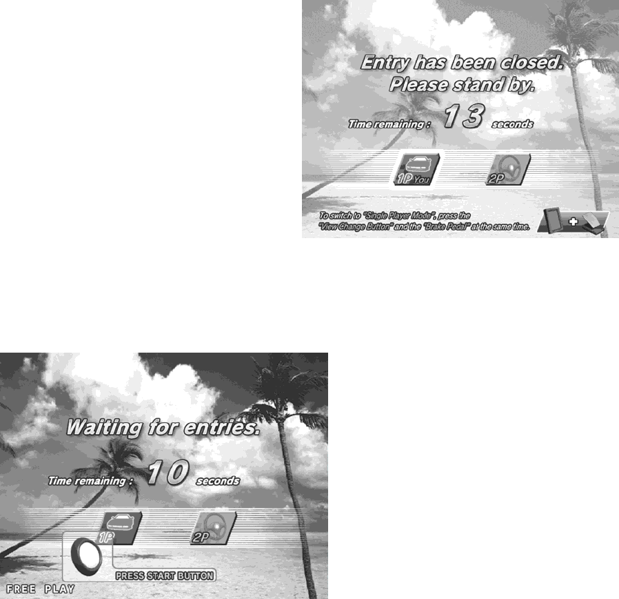
67
4.3. Setup Screen Order And Contents
This section explains the available options and controls for the setup screens.
4.3.1. Versus Mode Entry
If several machines are linked together, inserting
a coin and pressing the Start Button on one
machine will result in the message "Entry has
been closed. Please stand by." to be displayed on
the screen, following which opposing players
have the chance to enter the race on other
machines.
Any linked machines that players can race on display the message, "Waiting for entries." Other players can
join the race by inserting a coin and pressing the Start Button.
Note: See the later section "Versus Play Setup" for details of game flow after all players have joined the
race.
4.3.1.1.Closing Versus Mode Entry
To close Versus Mode entry, press the View Change Button and the Brake pedal at the same time before
other players join. (Press the Brake pedal while holding down the View Change Button.)
Versus Mode entry time can also be run down to "0" by holding the Start Button, thus closing Versus Mode
entry.
By closing Versus Mode entry in either of the above ways, the Single Player mode will commence, provided
no players have already joined.
Note: See the later section "2. Single Player Setup" for details of game flow after a single player race has
been selected.
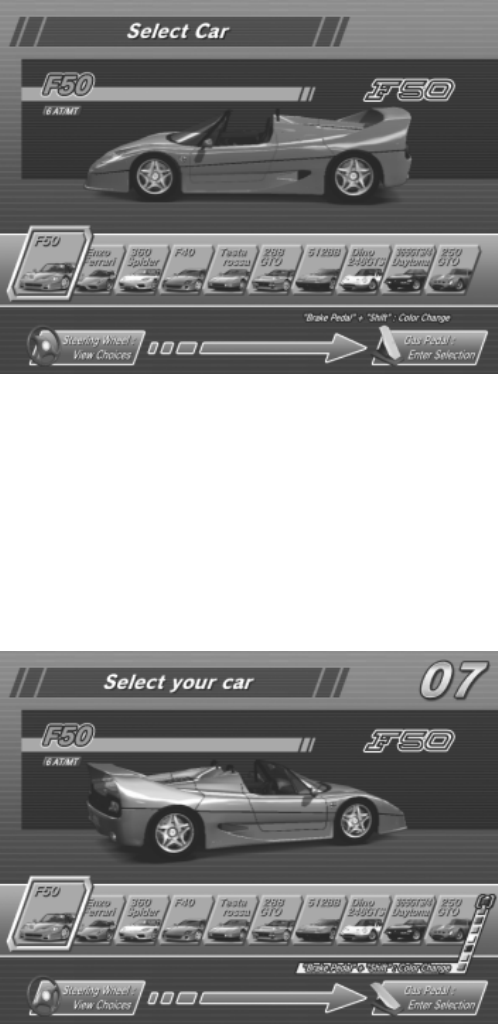
68
4.3.2. Single Player Setup
4.3.2.1.(1) Player’s Car Selection
Controls:
Steering Wheel: View Choices, Gas Pedal: Enter Selection, "Brake Pedal" + "Shift": Colour Change
The player can select one of the following 10 cars:
"F50", "Enzo Ferrari", "360 Spider" , "F40", "Testarossa", "288 GTO", "512 BB", "Dino 246 GTS", "365
GTS/4, Daytona", "250 GTO"
4.3.2.2.Changing the Car Colour
Pressing the Brake pedal displays the available colours for the player's car at the bottom-right of the
screen. A colour can be selected by moving the Gear Shifter up or down. In accordance with the selected
colour, the colour of the car displayed on the screen also changes.
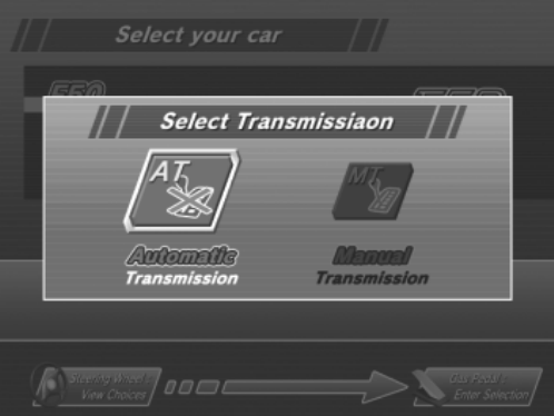
69
4.3.2.3.Transmission Selection
Controls:
Steering Wheel: View Choices, Gas Pedal: Enter Selection.
After the player has selected a car, they can then choose the type of transmission.
Automatic Transmission: Shifting up and down gears is performed automatically (the player does not
use the Gear Shifter).
Manual Transmission: The player shifts up and down gears using the Gear Shifter.
For Manual Transmission, the number of gears depends on the model of the car.
6-Speed: F50, Enzo Ferrari, 360 Spider
5-Speed: F40, Testarossa, 288 GTO, 512 BB, Dino 246 GTS, 365 GTS/4 Daytona, 250 GTO
70
4.3.2.4.Game Mode Selection
Controls:
Steering Wheel: View Choices, View Change Button: OutRun2/OutRun2SP, Gas Pedal: Enter Selection.
The player selects which game mode they will play.
OutRun Mode: Try to reach the goal with your girlfriend.
Earn points by overtaking enemy or rival cars on your way to the finish line.
Heart Attack Mode: Try to get as many "HEARTS" as possible by meeting your girlfriend's demands.
Carry out the various requests your girlfriend makes and try to accumulate hearts.
Time Attack Mode: Drive against the Ghost Car and challenge for the course record.
Compete against the fastest time achieved by another player on the machine (the
ghost car) to set a new record.
Note: See the section Game Instructions for further details of each mode.
Pressing the View Change Button allows the player to select the course from the previous game, OutRun2.
Pressing the View Change Button again allows the player to select the OutRun2SP course.
71
4.3.2.5.Game Mode Selection – 15 Continuous Course Mode
When the 15-Continuous Course Mode is available, two icons for that mode are added to the game mode
selection screen.
Note: See the section "Test Mode" for information on how to setup 15-Continuous Course Mode.
Points about the additional 15-Continuous Course Mode:
OutRun 15-Continuous Course Mode:
This allows the player to race 15 consecutive stages in OutRun Mode.
Time Attack 15-Continuous Course Mode:
This allows the player to race 15 consecutive stages in Time Attack Mode.
Note: See the section "Game Instructions" for details of the 15-Continuous Course.
If the player has insufficient credits to play the 15-Continuous Course Mode, the outstanding required
credits are displayed above the course icons. In this state, it is not possible to select that mode.
72
Pressing the View Change Button enables the selection of courses from the previous game, OutRun2. It is
possible to select a 15-Continuous Course from OutRun2.
4.3.2.6.Settings Selection (Time Attack Mode only)
In Time Attack Mode, the player proceeds to the car settings screen after selecting the game mode.
Controls:
Steering Wheel: View Choices, Gas Pedal: Enter Selection
The following settings are available:
Normal: Emphasis on handling, with a top speed of 293 km/h.
Tuned: Emphasis on speed, reaching 300 km/h maximum.
Note: The Tuned setting is aimed at experienced players as handling is made more difficult.
73
4.3.2.7.BGM Selection
Controls:
Steering Wheel: View Choices, View Change Button: Music Change, Gas Pedal: Enter Selection, Brake
Pedal + Shift: Sound Balance Change
The in-game background music can be chosen from a total of 14 different tunes.
By selecting the RANDOM icon on the far right, the music will be selected at random.
The list of selectable music can be changed by pressing the View Change Button.
BGM List: First screen
- SPLASH WAVE
- MAGICAL SOUND SHOWER
- PASSING BREEZE
- Risky Ride
- Shiny World
- Night Flight (Includes lyrics)
- Life was a bore (Includes lyrics)
BGM List: Second screen
- SPLASH WAVE -1986-
- MAGICAL SOUND SHOWER -1986-
- PASSING BREEZE -1986-
- Shake the Street -1989-
- Rush a Difficulty -1989-
- Who are you -1989-
- Keep Your Heart -1989-
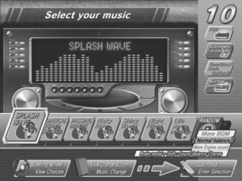
74
Sound Balance Adjustment
Pressing the Brake pedal brings up the sound balance window at the bottom right of the screen. The sound
balance can be adjusted by moving the Gear Shifter up or down.
Depending on the chosen sound balance, the relative volume of the BGM and engine noise varies.
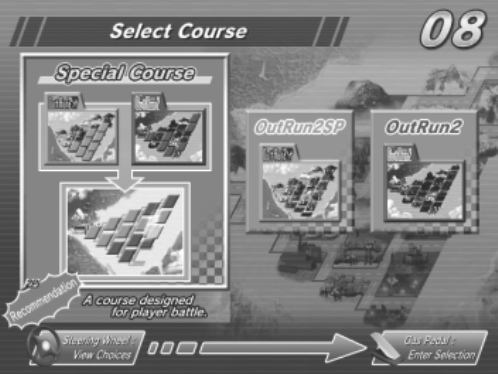
75
4.3.3. Versus Play Setup
4.3.3.1.Versus Stage Selection
Controls:
Steering Wheel: View Choices, Gas Pedal: Enter Selection
The player selects which stages the race will contain.
Special: A course specially designed for versus races.
This course combines stages from both OutRun2SP and OutRun2.
OutRun2SP: The OutRun2SP course.
OutRun2: The OutRun2 course.
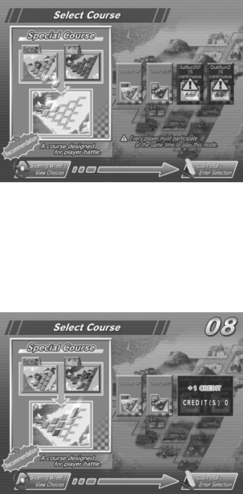
76
4.3.3.2.Versus Stage Selection (15-Continuous Course Mode)
When the 15-Continuous Course Mode is available, two icons for that mode are added to the versus stage
selection screen.
Note: See the section "Test Mode" for information on how to setup 15-Continuous Course Mode.
Points about the additional 15-Continuous Course Mode:
OutRun2SP 15-Continuous Course Mode:
This allows the player to race 15 consecutive stages in OutRun2SP Mode.
OutRun2 15-Continuous Course Mode:
This allows the player to race 15 consecutive stages in OutRun2 Mode.
Note: See the "Game Instructions" section for details of the 15-Continuous Course Mode.
If the player has insufficient credits to play the 15-Continuous Course Mode, the outstanding required
credits are displayed above the course icons. In this state, it is not possible to select that mode.
It is only possible to play the 15-Continuous Course Mode if all drivers participating in the race select it.
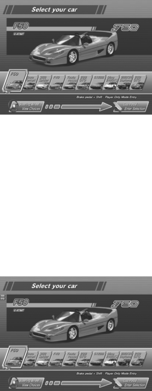
77
4.3.3.3.Player's Car Selection
Controls:
Steering Wheel: View Choices, Gas Pedal: Enter Selection, Brake pedal + Shift: Player Only Mode "PO"
Entry, (View Change + Shift: No Handicap "NH" Entry)
As with Single Player mode, there are 10 cars to choose from.
In Versus Play mode, car colours are fixed - Player 1: Red, Player 2: Yellow, Player 3: White or Silver
(depending on the car model), Player 4: Black.
No Handicap Setup
When a player is in 2nd position or below during Versus Play, they are compensated to help them catch the
lead driver more easily.
No Handicap is a mode without this compensation.
Pressing [View Change + Shift] (moving the Gear Shifter while pressing the View Change Button) displays
the "NH" icon on the left edge of the screen.
If all players participating in the race perform this operation, the race will take place in No Handicap mode.
Player Only Setup
In Player Only mode, no cars appear during the race other than the player's own car.
Pressing [Brake Pedal + Shift] (moving the Gear Shifter while pressing the Brake Pedal) displays the "PO"
icon on the left edge of the screen.
If all players participating in the race perform this operation, the race will take place in Player Only mode.
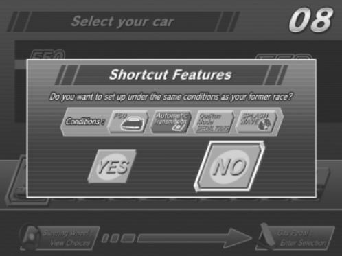
78
4.3.3.4.Transmission Selection
This operation is carried out in the same way as described in the section "2. Single Player Setup".
4.3.3.5.BGM Selection
This operation is carried out in the same way as described in the section "2. Single Player Setup".
4.3.4. Special Controls
Shortcut
During setup, the player can choose to start with the same settings as the previous game by performing the
following operation:
[Brake + View Change + Shift Up (putting the Gear Shifter in the down position while pressing the Brake
Pedal and the View Change Button)].
This combination of controls opens the shortcut window on the screen.
By turning the Steering Wheel to highlight "YES" and selecting it with the Gas pedal, play starts with the
same settings as the previous game.
If "NO" is selected, the window closes and the player is returned to the setup screen.
Note: If the previous game was played in 15-Continuous Course Mode it is not possible to use this
shortcut.

79
4.4. Game Instructions
4.4.1. Common Features in All Modes
4.4.1.1.Display Breakdown (All Modes)
The time counter is displayed at the top-centre of the screen.
If the time counter reaches zero, the game is over.
Extra time is added when a checkpoint is passed.
When slipstreaming, "Slipstream" is displayed underneath the time counter.
At the top-left of the screen the total time (in Single Player mode), position (in Versus Play mode) and route
map are displayed.
The total time shows how much time has passed since the start of the game (in Single Player
mode).
The position display shows the position the player is currently in, between the start and the finish
line (in Versus Play mode).
The route map shows the route the player has taken up to this point.
(An icon is displayed to the side of this at forks indicating the next stage.)
At the bottom-left of the screen the speed meter and tacho meter are displayed, as well as the shift and
shift-up indicators.
The speed meter shows the player's current speed.
(When slipstreaming, the colour of the number changes to blue.)
The tacho meter shows the speed the engine is currently revving at.
The shift indicator shows the currently engaged gear.
The shift-up indicator lets the player know the correct time to move up a gear.
(It flashes red when it is time to shift up a gear.)
Note: The shift-up indicator is not displayed if the player has selected Automatic Transmission.
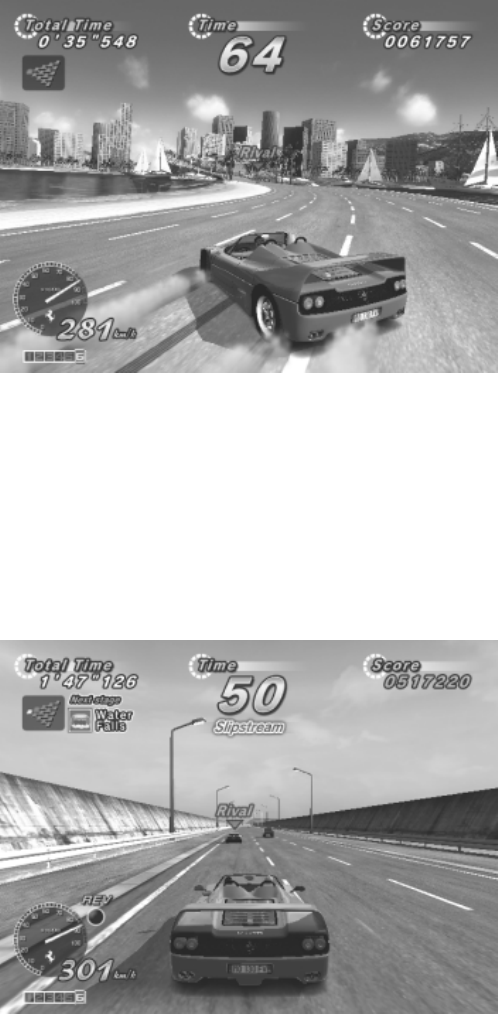
80
4.4.1.2.Game Controls (All Modes)
How to Drift
1) After letting go of the Gas pedal, immediately press the Brake pedal.
2) Turn the Steering Wheel hard and fast in the direction of a corner and press the Gas pedal.
OR
When using Manual Transmission, drop down a gear just before a corner and turn the Steering Wheel hard
in the direction of the corner.
Slipstreaming
By driving behind an enemy car or the car of another player, it is possible to pick up a slipstream.
When slipstreaming, the player experiences enhanced acceleration and can drive faster than the car's
specified top speed.
The following changes are seen when slipstreaming:
"Slipstream" appears below the time counter.
The colour of the speed meter display turns blue.
The engine noise becomes slightly louder.

81
4.4.2. Single Player: OutRun Mode
4.4.2.1.Display Breakdown
The score is displayed at the top-right of the screen, underneath this is an animated display of any points
received for passing enemy cars.
4.4.2.2.Game Instructions
Put simply, this is a mode where you enjoy taking a drive with a girl.
Choose either the left or right road when you come to a fork and aim to reach the finish line within the time
limit.
There are different endings depending on which finish line you cross.
Your score goes up each time you overtake a faster enemy car.
Hints for attaining a high score
Among the enemy cars there is a rival car which is marked with the word "RIVAL" above it.
The rival car is fast and difficult to pass, but there is a large point bonus if you do manage to.
The score you get for passing enemy cars varies depending on how you take them.
Try to find the highest scoring method for overtaking.

82
4.4.3. Single Player: Heart Attack Mode
4.4.3.1.Display Breakdown
The number of hearts collected is displayed at the top-right of the screen.
At the bottom-right of the screen, the total number of hearts collected and a girl's silhouette is displayed.
As the total number of hearts collected increases, the girl's silhouette is filled out with colour.
4.4.3.2.Game Instructions
In this mode, you impress a beautiful girl by doing everything she asks.
You must collect hearts which give an indication of how impressed the girl is with you.
You have to carry out the girl's requests in the interval between "START" and "END" being displayed.
You collect hearts in accordance with how well you carry out the various requests your girl asks of you.
The girl rates your performance in the following levels:
AAA, AA, A, B, C, D, E
Hints for picking up a lot of hearts
Crashing or bumping into enemy cars reduces the number of hearts you can get, so drive carefully.
If you continually achieve good ratings you may be given a "Special Request". That's your chance to really
impress her and get a triple-A score!

83
4.4.4. Single Player: Time Attack Mode
4.4.4.1.Display Breakdown
At the top-right of the screen, the lap time for each stage is displayed.
(If the time is faster than the ghost car, it is displayed in green.)
At the bottom-right of the screen, the time for each sector of the stage is displayed.
When each sector is completed, ghost car information is displayed on the centre left and right of the
screen.
On the left is data for the ghost car that took the left-hand road at the fork.
On the right is data for the ghost car that took the right-hand road at the fork.
The data is displayed in the following order:
The ghost car icon (model and colour), and the ghost car driver's name.
Ghost: The ghost car's sector completion time.
Player: The player's sector completion time.
Diff: The time difference between the ghost car and player's completion times.
(In green if the player is faster than the ghost car or red if the player is slower.)
The car's setup and transmission are shown at the bottom-left of the screen.
4.4.4.2.Game Instructions
In this mode you compete against the ghost car's time.
You aim to overtake the ghost car on each course and record your own fastest time to become the ghost
car.
The ghost car represents the fastest recorded time on each stage.
If you drive faster than the ghost car, your player data will be recorded as the ghost car data, and any
subsequent plays of the same stage will operate with your car as the ghost car.
84
If you enter your name on the name entry screen you can also add that to the ghost car data.
Even if you quit the game part way through, if you have recorded a faster time than the ghost car, you will
have the opportunity to enter your name.
Each stage has data for two ghost cars; one which took the left-hand road at the fork and one which took
the right-hand road.
The fifth stage has no fork so there is only data for one ghost car.
The fastest player on each course is saved separately as the top ghost car.
If you enter the fifth stage within 1 second of the fastest player, the top ghost car appears in addition to the
normal ghost car. ("TOP" is shown above the car.)
If you beat the top ghost car, you become the fastest player for that course.
Pressing the Start Button toggles the display of the ghost car on and off.
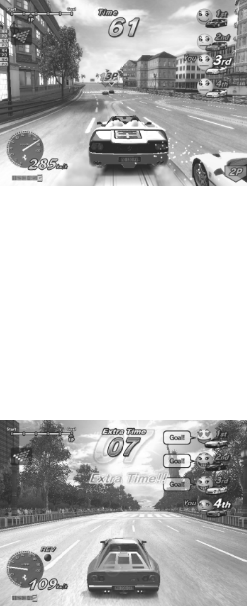
85
4.4.5. Versus Play
4.4.5.1.Display Breakdown
Opponent data is displayed at the top-right of the screen.
Each player's information is indicated with a face icon, and their current status is shown by the expressions
on the faces and with speech.
The order of the faces changes to reflect the race order.
4.4.5.2.Game Instructions
The starting grid order is determined by the order of entry into the game.
The first player to reach a fork can decide whether the race will continue down the left-hand or right-hand
road.
It is possible to set "No Handicap" mode, which eliminates compensation for trailing drivers, or "Player
Only" mode, where enemy cars are not displayed.
Note: See the previous section "Versus Play Setup" for details.
As soon as one of the competing players passes the finish line, the time counter display shows "Extra
Time".
The game is over for players who do not manage to finish within the "Extra Time" period.

86
4.4.6. 15-Continuous Course Mode
When 15-Continuous Course Mode is enabled, the following game modes are available:
"OutRun 15-Continuous Course Mode" (Single Player)
"Time Attack 15-Continuous Course Mode" (Single Player)
"OutRun2SP 15-Continue Course Mode" (Versus Play)
"OutRun2 15-Continuous Course Mode" (Versus Play)
The 15-Continuous Course Mode differs from the normal game in the following ways:
4.4.6.1.Display Breakdown
The following differences are exhibited in the 15-Continuous Course Mode:
The route map changes to the 15-Continuous Course map.
In Versus Play, the position display is modified.
4.4.6.2.Game Instructions
The 15-Continuous Course is a course combining all 15 stages.
The stages are interconnected in the following order:
1A - 2A - 2B - 3A - 3B - 3C - 4A - 4B - 4C - 4D - 5A - 5B - 5C - 5D - 5E
At the end of each stage, both branches of the left-right fork lead to the same stage that follows.
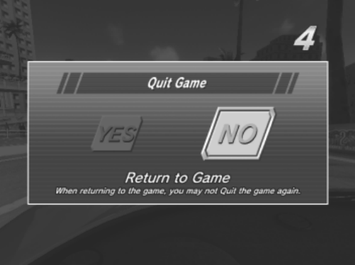
87
4.4.7. Game Pause
The game can be paused with the following combination of controls (in Single Player mode only):
With the car stopped, press [Brake + View Change + Shift Up (Put the Gear Shifter in the down position
while pressing the Brake Pedal and View Change Button down)]
This combination of controls opens the pause window on the screen.
By turning the Steering Wheel to highlight "YES" and selecting it with the Gas pedal, the game comes to an
end.
If "NO" is selected game play resumes.
(After "NO" has been selected once, it is no longer possible to use the game pause command again.)
The game pause command will not work in the following circumstances:
1) When the player is in the vicinity of the start area.
2) When the remaining time is 8 seconds or less.
3) When the game has already been paused once before, and "NO" was selected.

88
4.5. Name Entry And Internet Ranking
4.5.1. 1. Name Entry
Controls:
Steering Wheel: View Choices, Gas Pedal: Enter Selection, Brake Pedal: Delete, Start Button: END
(Moving the Gear Shifter up and down selects letters.)
This game has a function that can register all Single Player results with an Internet ranking system.
After finishing a game in Single Player mode, the player enters their name for Internet ranking purposes,
even if they have not achieved a rank on the actual machines they are playing on.
If the player gets into the ranking on the machine they are using, the name they enter will be used in that
machine's advertising demo display.
If the player makes a new ghost car record, their name is displayed with the new ghost car data.
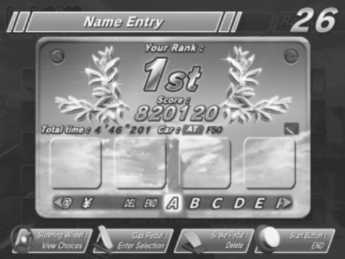
89
4.5.2. Internet Ranking
After the player has entered their name, an Internet ranking password is displayed.
Pressing the View Change Button switches to the game's in-depth data display.
Visit the following URL for Internet ranking registration and listings: http://outrun.jp/
The Internet ranking is calculated separately for the following game modes and courses:
OutRun2SP Courses
OutRun Mode: Each course (A - E) + the 15-Continuous Course
Heart Attack Mode: Each course (A - E)
Time Attack Mode [Normal, AT]: Each course (A - E) + the 15-Continuous Course
Time Attack Mode [Normal, MT]: Each course (A - E) + the 15-Continuous Course
Time Attack Mode [Tuned, AT]: Each course (A - E) + the 15-Continuous Course
Time Attack Mode [Tuned, MT]: Each course (A - E) + the 15-Continuous Course
OutRun2 Courses
OutRun Mode: Each course (A - E) + the 15-Continuous Course
Heart Attack Mode: Each course (A - E)
Time Attack Mode [Normal, AT]: Each course (A - E) + the 15-Continuous Course
Time Attack Mode [Normal, MT]: Each course (A - E) + the 15-Continuous Course
Time Attack Mode [Tuned, AT]: Each course (A - E) + the 15-Continuous Course
Time Attack Mode [Tuned, MT]: Each course (A - E) + the 15-Continuous Course
90
4.6. Character Introductions
Three major characters appear in the game.
1. Driver
Name: Alberto
Personal Info: Although easy-going on the outside, he's a real go-getter.
He has a very distinguished driving sense. He's also quite rich.
2. OutRun Mode Lady
Name: Jennifer
Personal Info: She's a filthy rich 'princess', always selfishly seeking the next thrill. She's involved with
Alberto, his Ferrari a present from her. She has a sharp eye for driving techniques.
3. Heart Attack Lady
Name: Clarissa
Personal Info: She's peppy and unmistakably sexy. A driving fan, with a weakness for thrill rides.
She's very demanding, but her sweet character makes her hard to dislike.
91
5. MAINTENANCE INSTRUCTIONS
5.1. Explanation of Test and Data Display
Use the switches on the VTS to enter the TEST MODE. This will allow you to carry out post installation and
periodic checks and adjustments. The following section details the function of each of the tests:
• Be very careful about entering TEST MODE. If the machine you wish to test is
linked to other machines, exiting test on your machine will cause a network check
to be carried out. This will disable all other machines linked to it.
ITEM DESCRIPTION / REFERENCE INTERVAL
INSTALLATION
OF THE
MACHINE
When the machine is installed perform the following checks:
Check to see that each setting is as per the standard settings input at
the time of shipment.
In the INPUT TEST mode, check each switch and VR. Section 5.4.1
In the OUTPUT TEST mode, check each of the lamps. Section 5.4.2
In the MEMORY TEST mode check all of the IC’s on the IC BD.
Section 5.3.1
Monthly
MEMORY On the TEST MENU screen choosing the MEMORY TEST allows self
test to be performed. In this test RAM & ROM are tested.
Monthly
PERIODIC
CHECKS
Periodically perform the following
MEMORY TEST. Section 5.3.1
Ascertain each setting:
In the INPUT TEST mode, test the control devices. Section 5.4.1
In the OUTPUT TEST mode, check each of the lamps. Section 5.4.2
Monthly
CONTROL
SYSTEM
In the INPUT TEST mode, check each switch and VR. Section 5.4.1
Adjust or replace each switch and VR.
Monthly
MONITOR In the CRT TEST mode, check to ensure the monitor is adjusted
correctly. Section 5.3.1.5
Clean screen (switch off machine and remove the plug)
Monthly
Weekly
IC BOARD MEMORY TEST
In the SOUND TEST mode, check the sound related ROMs. 5.3.1.4
Monthly
DATA CHECK Check such data as held in the bookkeeping screens, relating to
number and length of plays. Section 5.3.2.6
Monthly
EXTERIOR
MAINTENANCE
Clean surfaces
Lubricate seat sliders
Monthly
COIN
MECHANISM
Check switch operation (if fitted) Monthly
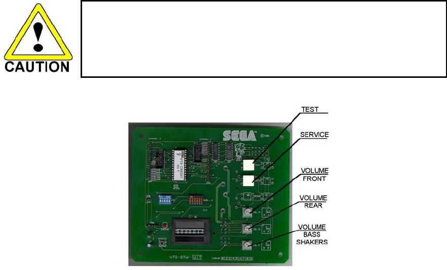
92
5.2. VTS Assembly
Do not touch places other than those specified. Touching places not specified could
cause an electric shock or short circuit..
Opening the Coin Chute door will reveal the VTS Assembly shown above. The function of each switch is as
follows.
TEST BUTTON (TEST SW): Used to enter TEST mode. Also has function during TEST
mode. Refer to the later section detailing TEST mode.
SERVICE BUTTON (SERVICE SW): Gives credits without registering on the coin counter. Also
used during TEST mode.
VOLUME FRONT: Adjusts the volume of the left, right and control panel
speakers.
VOLUME REAR: Adjusts the volume of the woofer behind the seat.
VOLUME BASS SHAKER: Adjusts the output of the control panel bass shaker.
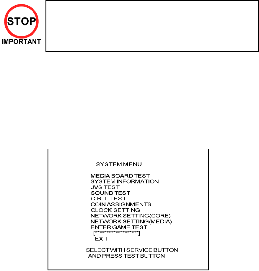
93
5.3. System Test Mode
Any settings that are changed by users during TEST MODE are saved upon exiting TEST MODE with the
EXIT command in the SYSTEM MENU. If the unit is powered off prior to exiting, changes to settings will not
take effect.
You may not enter GAME TEST MODE while the unit is reading from or
checking the GD-ROM. If error messages are displayed when exiting TEST
MODE, you should power the unit off and on again.
In the manual for this product, "Media Board" and "DIMM" are one and the
same.
Use with the specified settings. If settings other than those specified are
used, inappropriate operations or malfunction may occur
5.3.1. System Test Menu Mode
System Test Mode can be used to check that the main circuit operations are correct, adjust Monitor colour,
and perform coin/credit settings.
However, this product can only be used with the settings shown below.
SOUND TEST
- OUTPUT TYPE: STEREO
COIN ASSIGNMENTS
- COIN CHUTE TYPE: COMMON
- SERVICE TYPE: COMMON
1. Press the TEST Button after powering on the unit to display the following SYSTEM MENU.
2. Press the SERVICE Button to move the cursor to the desired test item.
3. Move the cursor to the desired item and press the TEST Button to display each test screen.
4. Move the cursor to ENTER GAME TEST and press the TEST Button to enter the individual test
menus for each game. Refer to "9-3 GAME TEST MODE".
5. When testing is complete, move the cursor to EXIT and press the TEST Button. The game
advertisement screen should be displayed.
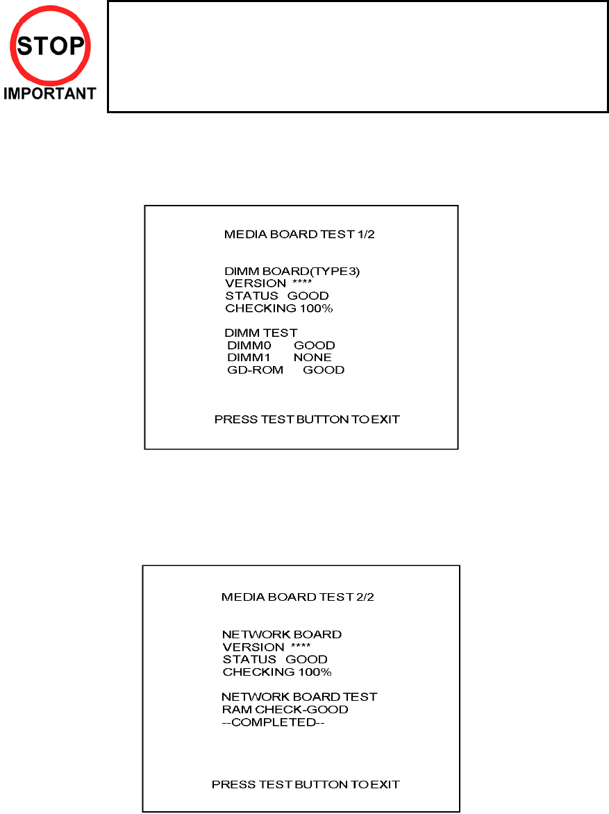
94
5.3.1.1.Media Board Test
Powering off the system during the MEDIA BOARD TEST with a DIMM BOARD will
erase the game programme data. It may be necessary to reload the data.
Always wait for the test to complete before attempting to exit.
MEDIA BOARD TEST is used to check the memory and IC on the MEDIA BOARD connected to the
Chihiro. Test screens and test times may differ depending on the type of MEDIA BOARD connected to the
unit.
Note: The following is the MEDIA BOARD TEST screen for a unit with a DIMM BOARD.
1. MEDIA BOARD TEST begins immediately upon entering this test mode.
2. If "GOOD" is displayed to the right of each item, the MEDIA BOARD components are functioning
properly.
3. Press the TEST Button to display the following screen.
4. After the test is complete, move the cursor to EXIT and press the TEST Button to return to the
SYSTEM MENU screen.
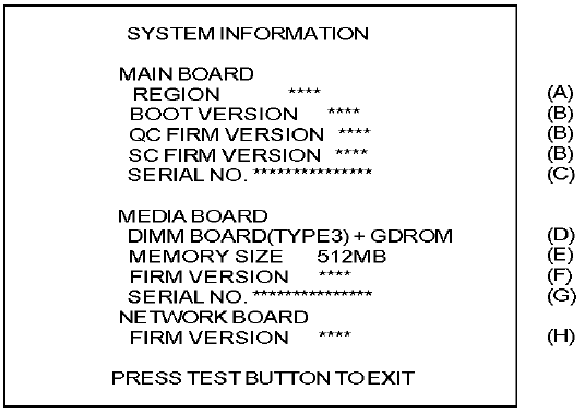
95
5.3.1.2.System Information
Use SYSTEM INFORMATION to check version and other information for system programmes.
Screens may differ depending on the type of MEDIA BOARD connected to the unit.
Press the TEST Button to return to the SYSTEM MENU screen.
A REGION
The COUNTRY CODE of the MAIN BOARD.
B BOOT VERSION, QC FIRM VERSION, SC FIRM VERSION
Version information for the MAIN BOARD system programmes.
C SERIAL NO.
Serial number of the MAIN BOARD.
D DIMM BOARD + GDROM
Type of MEDIA BOARD. This example shows a DIMM BOARD with a GD-ROM DRIVE connected.
E MEMORY SIZE
Capacity of DIMM memory installed on the DIMM BOARD.
F FIRM VERSION
Version information for the DIMM BOARD system programme.
G SERIAL NO.
Serial number of the DIMM BOARD.
H FIRM VERSION
Version information for the NETWORK BOARD system programme.
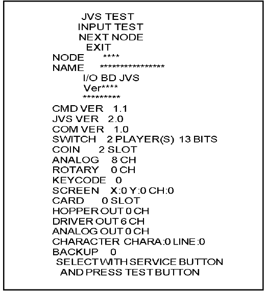
96
5.3.1.3.JVS Test
JVS TEST is used to verify the specs of the I/O BOARD connected to the Chihiro and to run input tests.
I/O BOARD specs are displayed initially.
Screens may differ depending on the type of I/O BOARD connected to the unit.
1. Use the SERVICE Button to move the cursor to the desired test item.
2. Move the cursor to INPUT TEST and press the TEST Button to enter the INPUT TEST screen for
the I/O BOARD currently displayed.
3. When 2 or more I/O BOARDS are connected, move the cursor to NEXT NODE and press the
TEST Button to enter the test screen for the next I/O BOARD. The lower the NODE number, the
further away the node is from the Chihiro.
4. Move the cursor to EXIT and press the TEST Button to return to the SYSTEM MENU screen.
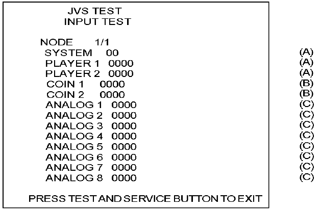
97
Input Test Screen
5. On-screen values change according to the input from switches and the volume.
A) SYSTEM, PLAYER
Values change with input from control panel/other switches.
B) COIN
Increases with input from the COIN SWITCH. The count is cleared when exiting
TEST MODE.
C) ANALOG
Displays analog values from "0000" to "FFFF".
6. Press the SERVICE and TEST Buttons simultaneously to return to the JVS TEST main screen.
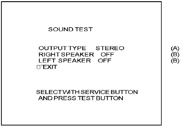
98
5.3.1.4.Sound Test
Use SOUND TEST to test sound output and to select the stereo/mono/surround setting.
1. Use the SERVICE Button to move the cursor to the desired test item.
2. Press the TEST Button to enter the selected item.
A) OUTPUT TYPE: STEREO, MONO, SURROUND
Select the sound output from the I/O PANEL audio output interface setting among
STEREO, MONO and SURROUND.
B) RIGHT/LEFT SPEAKER: ON, OFF
When set to "ON", the test sends a beep to each audio output interface. Only the
word "SPEAKER" is displayed when the OUTPUT TYPE is set to "MONO", and
when set to "ON", the test sends the same beep to both the left/right audio output
interfaces.
To test surround output, it is necessary to use a separate Audio Amp, and receive
signal from a terminal not in use at the time of shipping.
Note: Not available with this product.
3. Move the cursor to EXIT and press the TEST Button to return to the SYSTEM MENU screen.

99
5.3.1.5.C. R. T. Test
Use the C.R.T. TEST to adjust monitor colours and verify screen size.
COLOUR CHECK Screen
1. Monitor COLOUR CHECK screen is displayed initially.
Each of the colours (red, green and blue) is darkest at the far left and gets progressively
lighter (32 steps) towards the right.
Monitor brightness is set correctly if the white colour bar is black at the left edge and white
at the right edge.
C.R.T TEST
PAGE 1/2
C.R.T. TEST 1/2
PRESS TEST BUTTON TO CONTINUE
RED
GREEN
BLUE
WHITE
2. Press the TEST Button to proceed to the next page.
SIZE CHECK Screen
C.R.T. TEST 2/2
PRESS TEST BUTTON TO EXIT
3. Adjust the CHECK GRID so that the entire GRID is displayed on the screen.
4. Press the TEST Button to return to the SYSTEM MENU screen.
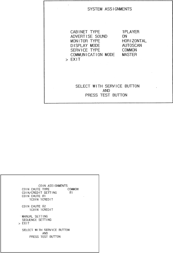
100
5.3.2. System Assignments
Allows system options to be set. Select required setting with SERVICE button, confirm with TEST button.
Default settings are indicated in parentheses.
• CABINET TYPE specifies Control Panel and number of Coin Chutes. The number of players displayed
in BOOKKEEPING varies in accordance with the value displayed here. (1PLAYER)
• ADVERTISE SOUND allows the sound emission to be turned (ON) or OFF during ADVERTISE MODE.
• MONITOR TYPE changes the orientation of the image on the screen (HORIZONTAL)
• SERVICE TYPE sets the functioning of the SERVICE button, should several SERVICE buttons exist.
INDIVIDUAL: Service credit is applied to the machine on which the SERVICE button is pressed.
(COMMON): Service credit is applied to all machines when SERVICE button is pressed.
5.3.2.1.Coin Assignments
Select the coin assignments mode to set the coin
to credit ratios.
This can be any of the pre-set values or can be
done manually.

101
5.3.2.2.Coin/Credit Setting (Coin Chute Common Type)
SETTING FUNCTIONING OF COIN CHUTE #1 FUNCTIONING OF COIN CHUTE #2
SETTING #1 1 COIN 1 CREDIT 1 COIN 1 CREDIT
SETTING #2 1 COIN 2 CREDITS 1 COIN 1 CREDIT
SETTING #3 1 COIN 3 CREDIT 1 COIN 1 CREDIT
SETTING #4 1 COIN 4 CREDITS 1 COIN 1 CREDIT
SETTING #5 1 COIN 5 CREDITS 1 COIN 1 CREDIT
SETTING #6 1 COIN 2 CREDITS 1 COIN 2 CREDITS
SETTING #7 1 COIN 5 CREDITS 1 COIN 2 CREDITS
SETTING #8 1 COIN 3 CREDITS 1 COIN 3 CREDITS
SETTING #9 1 COIN 4 CREDITS 1 COIN 4 CREDITS
SETTING #10 1 COIN 5 CREDITS 1 COIN 5 CREDITS
SETTING #11 1 COIN 6 CREDITS 1 COIN 6 CREDITS
SETTING #12 2 COINS 1 CREDIT 2 COINS 1 CREDIT
SETTING #13 1 COIN 1 CREDIT 2 COINS 1 CREDIT
SETTING #14 1 COIN 2 CREDITS 2 COINS 1 CREDIT
SETTING #15 1 COIN
2 COINS
1 CREDIT
3 CREDITS
1 COIN
2 COINS
1 CREDIT
3 CREDITS
SETTING #16 1 COIN 3 CREDITS 1 COIN
2 COINS
1 CREDIT
3 CREDITS
SETTING #17 3 COINS 1 CREDIT 3 COINS 1 CREDIT
SETTING #18 4 COINS 1 CREDIT 4 COINS 1 CREDIT
SETTING #19 1 COIN
2 COINS
3 COINS
4 COINS
1 CREDIT
2 CREDITS
3 CREDITS
5 CREDITS
1 COIN
2 COINS
3 COINS
4 COINS
1 CREDIT
2 CREDITS
3 CREDITS
5 CREDITS
SETTING #20 1 COIN 5 CREDITS 1 COIN
2 COINS
3 COINS
4 COINS
1 CREDIT
2 CREDITS
3 CREDITS
5 CREDITS
SETTING #21 5 COINS 1 CREDIT 5 COINS 1 CREDIT
SETTING #22 1 COIN 2 CREDITS 3 COINS
5 COINS
1 CREDIT
2 CREDITS
SETTING #23 2 COINS
4 COINS
5 COINS
1 CREDIT
2 CREDITS
3 CREDITS
2 COINS
4 COINS
5 COINS
1 CREDIT
2 CREDITS
3 CREDITS
SETTING #24 1 COIN 3 CREDITS 2 COINS
4 COINS
5 COINS
1 CREDIT
2 CREDITS
3 CREDITS
SETTING #25 1 COIN
2 COINS
3 COINS
4 COINS
5 COINS
1 CREDIT
2 CREDITS
3 CREDITS
4 CREDITS
6 CREDITS
1 COIN
2 COINS
3 COINS
4 COINS
5 COINS
1 CREDIT
2 CREDITS
3 CREDITS
4 CREDITS
6 CREDITS
SETTING #26 1 COIN 6 CREDITS 1 COIN
2 COINS
3 COINS
4 COINS
5 COINS
1 CREDIT
2 CREDITS
3 CREDITS
4 CREDITS
6 CREDITS
SETTING #27 FREE PLAY FREE PLAY

102
5.3.2.3.Coin/Credit Setting (Coin Chute Individual Type)
SETTING FUNCTIONING OF COIN CHUTE #1
SETTING #1 1 COIN 1 CREDIT
SETTING #6 1 COIN 2 CREDITS
SETTING #8 1 COIN 3 CREDITS
SETTING #9 1 COIN 4 CREDITS
SETTING #10 1 COIN 5 CREDITS
SETTING #11 1 COIN 6 CREDITS
SETTING #12 2 COINS 1 CREDIT
SETTING #15 1 COIN
2 COINS
1 CREDIT
3 CREDITS
SETTING #17 3 COINS 1 CREDIT
SETTING #18 4 COINS 1 CREDIT
SETTING #19 1 COIN
2 COINS
3 COINS
4 COINS
1 CREDIT
2 CREDITS
3 CREDITS
5 CREDITS
SETTING #21 5 COINS 1 CREDIT
SETTING #22 3 COINS
5 COINS
1 CREDITS
2 CREDITS
SETTING #23 2 COINS
4 COINS
5 COINS
1 CREDIT
2 CREDITS
3 CREDITS
SETTING #25 1 COIN
2 COINS
3 COINS
4 COINS
5 COINS
1 CREDIT
2 CREDITS
3 CREDITS
4 CREDITS
6 CREDITS
SETTING #27 FREE PLAY
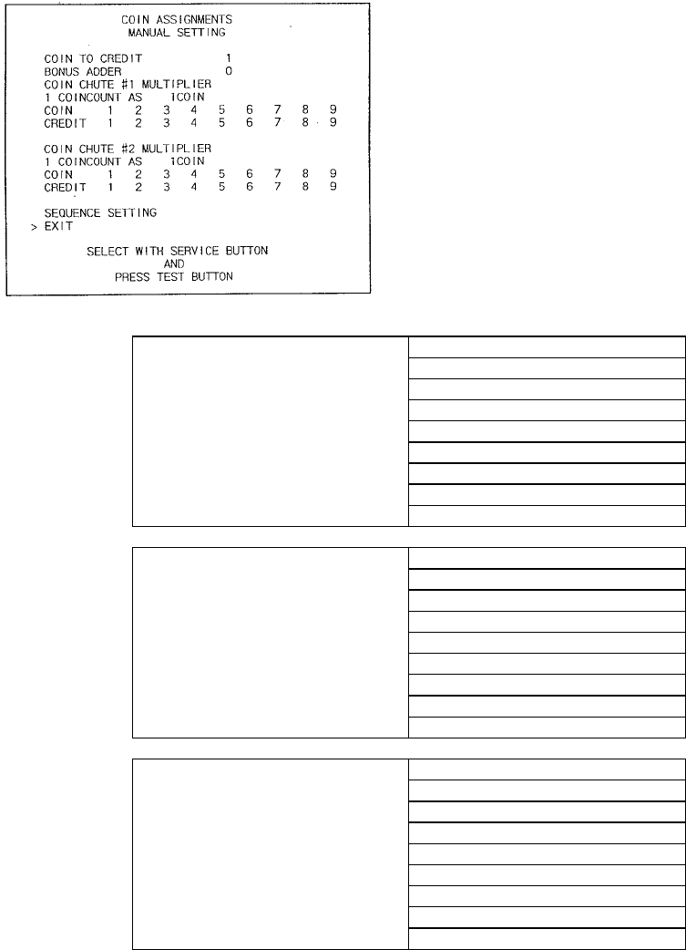
103
5.3.2.4.Manual Setting
Select manual setting to manually set the coin to
credit ratios.
The available combinations are detailed below.
MANUAL SETTING
COIN TO CREDIT 1 COIN 1 CREDIT
2 COINS 1 CREDIT
3 COINS 1 CREDIT
4 COINS 1 CREDIT
5 COINS 1 CREDIT
6 COINS 1 CREDIT
7 COINS 1 CREDIT
8 COINS 1 CREDIT
9 COINS 1 CREDIT
BONUS ADDER NO BONUS ADDER
2 COINS GIVE 1 EXTRA COIN
3 COINS GIVE 1 EXTRA COIN
4 COINS GIVE 1 EXTRA COIN
5 COINS GIVE 1 EXTRA COIN
6 COINS GIVE 1 EXTRA COIN
7 COINS GIVE 1 EXTRA COIN
8 COINS GIVE 1 EXTRA COIN
9 COINS GIVE 1 EXTRA COIN
COIN CHUTE MULTIPLIER 1 COIN COUNTS AS 1 COIN
1 COIN COUNTS AS 2 COINS
1 COIN COUNTS AS 3 COINS
1 COIN COUNTS AS 4 COINS
1 COIN COUNTS AS 5 COINS
1 COIN COUNTS AS 6 COINS
1 COIN COUNTS AS 7 COINS
1 COIN COUNTS AS 8 COINS
1 COIN COUNTS AS 9 COINS
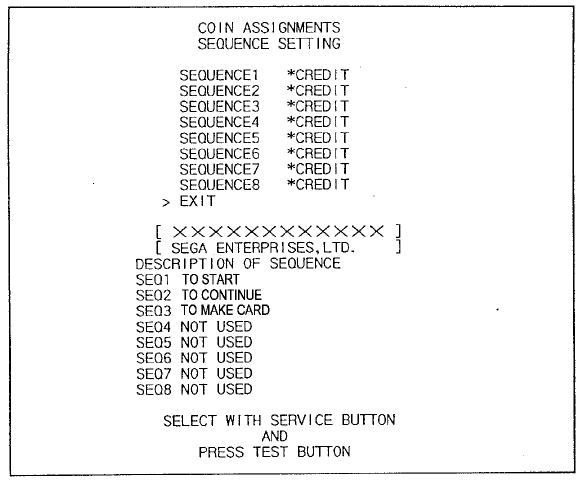
104
5.3.2.5.Sequence Setting
Selecting SEQUENCE SETTING allows the number of credits required to start the game to be set. Each
sequence can be set between 1 and 5. Select EXIT to return to the first screen.
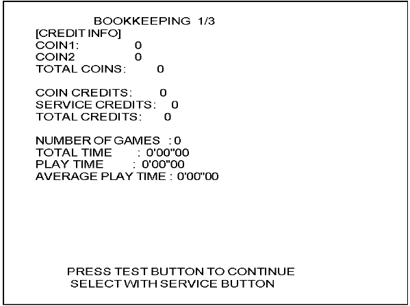
105
5.3.2.6. Bookkeeping
Select BOOKKEEPING to display the following three operating data screens.
Press the TEST Button on the BOOKKEEPING 1/3 and BOOKKEEPING 2/3 screens to move to the
second and third (BOOKKEEPING 3/3) screens. Press the TEST Button in the third screen to return to the
Game Test Menu Screen.
COIN1: The number of coins inserted into Coin Slot 1.
COIN2: The number of coins inserted into Coin Slot 2.
TOTAL COINS: The total number of coins inserted into the coin slots.
COIN CREDITS: The number of credits for the coins inserted.
SERVICE CREDITS: The number of credits input by the SERVICE Button.
TOTAL CREDITS: Total credits from coins and the SERVICE Button.
NUMBER OF GAMES: The total number of games played.
TOTAL TIME: The amount of time the unit has been in operation.
PLAY TIME: Total playing time.
AVERAGE PLAY TIME: Total play time divided by the total number of games played.
Press the TEST Button to move to screen 2/3 of BOOKKEEPING.
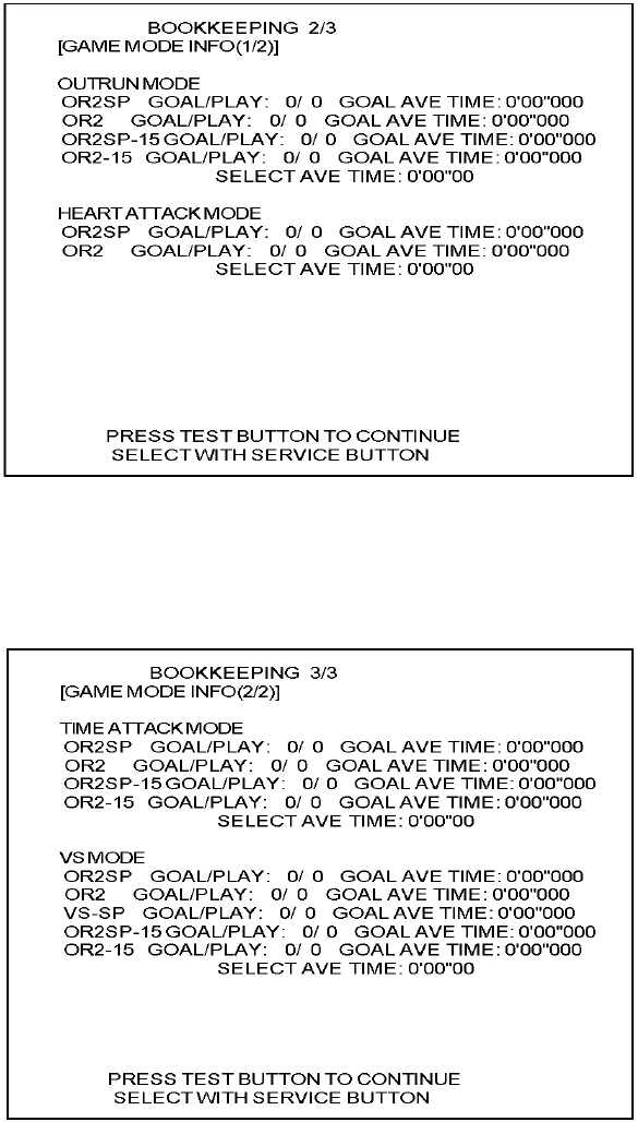
106
The number of goals, number of plays, and average time to reach the goal are displayed separately for
each of the courses in OutRun Mode and Heart Attack Mode. Use this data as a rough guide when
adjusting the difficulty setting.
Press the TEST Button to move to screen 3/3 of BOOKKEEPING.
The number of goals, number of plays, and average time to reach the goal are displayed separately for
each of the courses in Time Attack Mode and Versus Mode. Use this data as a rough guide when adjusting
the difficulty setting.
Press the TEST button to return to the Game Test Menu screen.
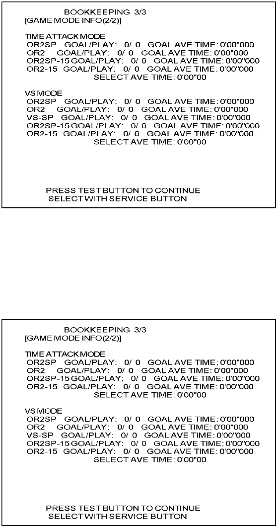
107
5.3.2.7.Backup Data Clear
Select BACKUP DATA CLEAR to display the following screen, and you can clear the BOOKKEEPING
data, top score ranking data, or coin/credit related data.
Select the data to clear.
CLEAR ALL BACKUP DATA: Initializes all of the data.
CLEAR RANKING & GHOST CAR DATA ONLY: Only initializes the ranking and ghost car data.
CLEAR BOOKKEEP DATA ONLY: Only initializes the BOOKKEEPING data.
Use the SERVICE Button to move the cursor to the item corresponding to the data to clear, then press the
TEST Button. The following confirmation screen is displayed.
To clear data, use the SERVICE Button to move the cursor to YES (CLEAR) and then press the TEST
Button. When the data has been cleared, the message "COMPLETED" will be displayed.
Press the TEST Button again to return to the Game Test Menu screen.
Move the cursor to NO (CANCEL) and press the TEST Button to return to the Game Test Menu screen
without clearing the data.
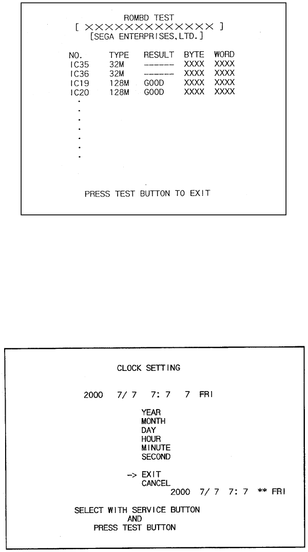
108
5.3.2.8.ROM BD Test
In this test, Game Board ROM is checked. If GOOD is displayed, it is satisfactory. The IC number, TYPE,
BYTE and WORD refer to the checksum of each unit. Press TEST to exit.
On above screen, IC35 and IC36 (program ROMs) do not display GOOD or BAD. Press TEST Button to
EXIT.
5.3.2.9. Clock Setting
YEAR, MONTH, DAY, HOUR and MINUTE are set for SEGA NAOMI BOARD. Select the desired item with
SERVICE button and press TEST to increase the value. Select EXIT to return to MENU mode.
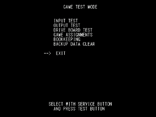
109
5.4. Game Test Mode
[IMPORTANT]
When changing the game configuration, changes will not be enabled until the Game Test Mode has
been completed. Be sure to exit the Game Test Mode properly after configuration changes.
Select GAME TEST MODE from the System Menu screen to display the Game Test Menu screen as
follows.
Use the SERVICE Button to move the cursor to the desired test item. Press the TEST Button to enter the
selected item.
NOTE: In Upright cabinet types, the DRIVE BOARD TEST is not necessary and the option will not be
displayed.
After selecting an item, read the explanations below regarding operation.
After the test is complete, move the cursor to EXIT and press the TEST Button to return to the System
Menu screen.
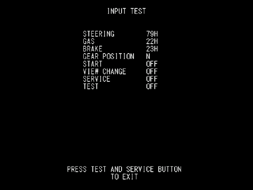
110
5.4.1. Input Test
Select INPUT TEST to display the following screen and check the status of input devices.
This test should be used periodically to check that each input device is functioning correctly.
Test the STEERING, GAS (ACCEL) and BRAKE controls to ensure that they are functioning properly and
that the parameters change smoothly as each input device is operated.
Display N, UP and DOWN using the GEAR POSITION. N displays that there is no control input. Verify that
both UP and DOWN display in sync with the position of the shift knob.
Press the START, CHANGE VIEW, SERVICE and TEST Buttons. If functioning correctly, each indicator will
switch from OFF to ON.
Press the SERVICE and TEST Buttons simultaneously to return to the Game Test Menu screen.
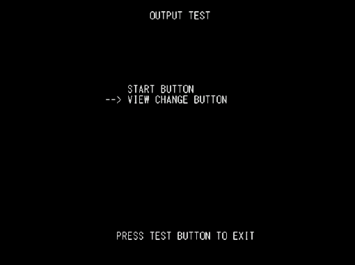
111
5.4.2. Output Test
Select OUTPUT TEST to display the following screen and check the status of each lamp.
This test should be used periodically to check that the lamps are functioning correctly.
On this screen the cursor will switch automatically between items, lighting up the respective lamps.
• START BUTTON : Lights up the START button.
• VIEW CHANGE BUTTON: Lights up the View Change button.
Press the TEST Button to return to the Game Test Menu screen.
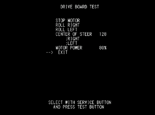
112
5.4.3. Drive Board Test
Select DRIVE BOARD TEST to display the following screen and check the status of steering motor.
Use the SERVICE Button to select the desired test item. Press the TEST Button to activate the selected
item.
NOTE: This test will not be displayed in Upright cabinet types.
• STOP MOTOR: Halts motor activity.
• ROLL RIGHT: Rotates steering wheel completely to the right.
• ROLL LEFT: Rotates steering wheel completely to the left.
• CENTRE OF STEER: Steering wheel motor’s centre of control is displayed.
RIGHT: Moves centre of control position to the right.
LEFT: Moves centre of control position to the left.
• MOTOR POWER: Sets the steering resistance.
There are four levels to choose from, 100% (strong resistance), 90%,
80%, and 60% (weak resistance). (80% is the default setting)
After changing the settings, select EXIT and press the TEST Button to return to the Game Test Menu
screen.
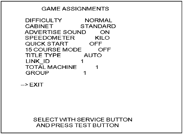
113
5.4.4. Game Assignments
Select GAME ASSIGNMENTS to display the current game settings and make changes.
Changes to settings are not enabled until Test Mode is exited. After changing settings, be sure to exit Test
Mode.
NOTE: When adjusting network play settings, DIFFICULTY, ADVERTISE SOUND, LANGUAGE,
SPEEDOMETER, and QUICK START items will be decided by the cabinet with LINK_ID "1". Changes
made to the game display or settings during game play do not affect the Game Test Menu settings.
Perform the following settings for each item.
DIFFICULTY: The game difficulty setting. There are 5 difficulty levels with VERY EASY being
the easiest setting and VERY HARD being the most difficult setting. (Default
Setting: NORMAL)
CABINET: The game cabinet type setting. Choose from either STANDARD or UPRIGHT.
ADVERTISE SOUND: The setting to turn the advertising sound ON/OFF.
(Default Setting: ON)
SPEEDOMETER: The speed display setting. During game play, KILO will be displayed as "km/h",
and MILE as "mph". Choose one of these options. (Default Setting: KILO)
QUICK START: Choose OFF or ON. The ON setting takes the player directly to the game
selection screen after entering credits into the machine. (Default Setting: OFF)
114
15 COURSE MODE: This is the 15 Continuous Course Mode setting. The length of time for 1 play is
longer than the normal game mode.
(Default Setting: OFF)
When this is set to OFF, players cannot play the 15 Continuous Course Modes.
When this is set to ON CHARGE, players can play the 15 Continuous Course
Modes. You should update the additional credit settings in GAME COST
SETTING under COIN ASSIGNMENTS in System Test Mode.
When this is set to ON FREE, players can play the 15 Continuous Course Modes
without any additional credits.
TITLE TYPE: This is the setting for the type of title screen. There are two types provided for the
title screen: the Stars and Stripes or clouds. (Default Setting: AUTO)
When this is set to AUTO, the type of title screen is determined by the REGION
setting on the main board.
For JAPAN and USA, the Stars and Stripes are selected, and for EXPORT, the
clouds are selected.
When this is set to AMERICA, the Stars and Stripes are selected, and when this
is CLOUD, the clouds are selected.
LINK_ID: The setting which determines the Player Number of each cabinet. It assigns
unique numbers for cabinets in a single group. Do not assign two or more
cabinets the same number. For network play, it is necessary to complete the
LINK_ID, TOTAL MACHINE, and GROUP settings for each cabinet.
(Default Setting: 1, Maximum: 4)
TOTAL MACHINE: The number of network connected game cabinets. (Sets the number of competing
cabinets in Versus Mode.) Setting this to "1" limits possible play modes to Single
Player mode only.
(Default Setting: 1, Maximum: 4)
GROUP: Used for dividing networked cabinets into groups. For example, to split up a group
of four networked machines into two groups of two cabinets, set two cabinets to
"1" and the other two cabinets to "2". Generally, setting all cabinets to "1" is
recommended.
After changing the settings, select EXIT and press the TEST Button to return to the Game Test Menu
screen.

115
Network Versus Mode Cabinet Settings
Cases for four cabinets (A, B, C, and D) connected via network cable.
4-Cabinet Versus
CABINET A B C D
LINK_ID 1 2 3 4
TOTAL MACHINE 4 4 4 4
GROUP 1 1 1 1
Status Four cabinets can compete.
3-Cabinet Versus
CABINET A B C D
LINK_ID 1 1 2 3
TOTAL MACHINE 1 3 3 3
GROUP 1 2 2 2
Status Single play only. Three cabinets can compete.
2-Cabinet Versus
CABINET A B C D
LINK_ID 1 2 1 2
TOTAL MACHINE 2 2 2 2
GROUP 1 1 2 2
Status Two cabinets can compete. Two cabinets can compete.
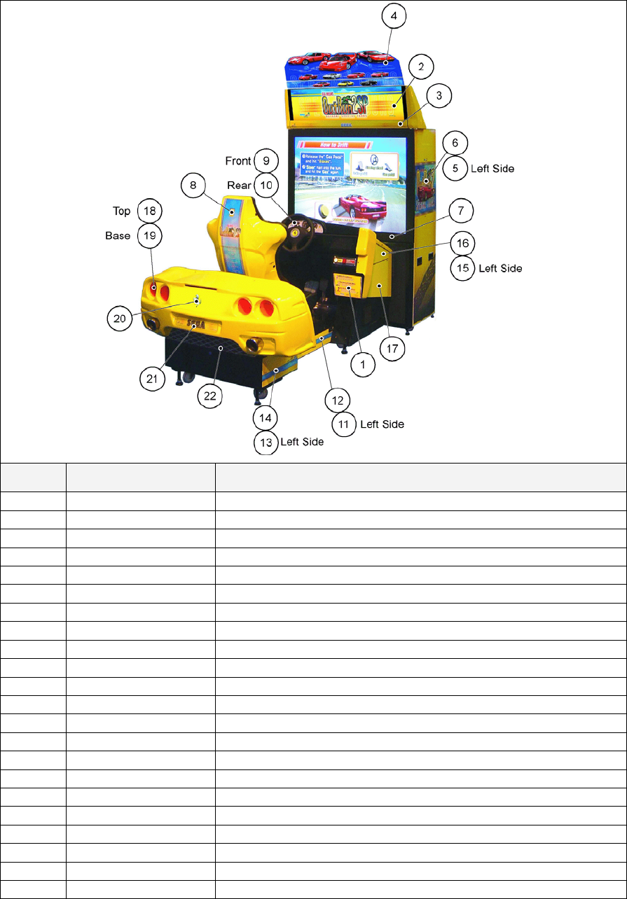
116
6. DESIGN RELATED PARTS
ITEM PART NO, DESCRIPTION
1 422-0932DUK PLAY INSTR SH ORP DX MULTI
2 ORP-0510UK BILLBOARD PLATE ORP
3 ORP-0511UK STICKER BILLBOARD F LOWER
4 ORP-0512UK POP PANEL ORP DX
5 ORP-1011UK STICKER PTV SIDE L
6 ORP-1012UK STICKER PTV SIDE R
7 ORP-1013UK STICKER WEB RANKING
8 ORP-1603-BUK STICKER SEAT BACK
9 ORP-2027-BUK METER PANEL A
10 ORP-2027-CUK METER PANEL B
11 ORP-2031-AUK STICKER CABI MID BASE BOX L
12 ORP-2031-BUK STICKER CABI MID BASE BOX R
13 ORP-2031-CUK STICKER CABI REAR BASE BOX L
14 ORP-2031-DUK STICKER CABI REAR BASE BOX R
15 ORP-2031-EUK STICKER CABI UPPER L
16 ORP-2031-FUK STICKER CABI UPPER R
17 ORP-2031-GUK STICKER CABI UPPER R DOOR
18 ORP-2365-AUK REAR LIGHT TOP
19 ORP-2365-BUK REAR LIGHT BASE
20 ORP-2366UK STICKER TAIL LIGHT CLUSTER
21 ORP-2367UK NUMBER PLATE
22 ORP-2369UK STICKER REAR FAIRING LOWER
117
7. PARTS LIST
7.1. Assembly Structure
ORP BOM STRUCTURE
ORP-0000UK ORP-1000UK NCR-0600UK
TOP ASSY OUTRUN SPECIAL TOURS DX ASSY PTV ASSY FRONT PANEL
ORP-2000UK ORP-2050UK ORP-2070UK
ASSY MAIN CABI ASSY FRONT CABI ASSY AC UNIT
FRI-2550
ASSY HANDLE MECHA
ORP-2350UK FRI-2600
ASSY REAR CABI ASSY PADDLE SHIFT TWIN
ORP-3020UK ORP-2260UK ORP-2027UK SPG-2027-AUK
ASSY BASE BOX FLOOR CENTRE ASSY CONTROL PANEL COVER R CTRL PNL COVER R BLANK UK
ORP-4100UK ORP-4000UK ORP-2028UK SPG-2028UK
ASSY AMP BD ASSY MAIN BD ASSY BULK BOARD COVER BULK BOARD COVER UK
ORP-4200UK ORP-6001UK SPG-2030-AUK
ASSY ELEC BD ASSY CABLE RUN CONPANE SIDE COVER R BLANK UK
ORP-2400UK ORP-2080UK SPG-2054-AUK
ASSY SEAT ASSY CTRL PANEL COVER F CTRL PANEL COVER F UK
ORP-3000UK
ASSY FRAME BASE
ORP-INST-D ORP-0500UK
ASSY INSTALLATION KIT ORP DX ASSY BILLBOARD
ORP-3100UK
ASSY COIN CHUTE TOWER

118
7.2. ORP-0000UK TOP ASSY OUTRUN SPECIAL TOURS DX
ITEM PART NO. QTY DESCRIPTION COMPONENT REF.
3 ORP-1000UK 1 ASSY PTV
4 ORP-2000UK 1 ASSY MAIN CABI
7 440-WS0220UK 2 WARNING STICKER TRAP HAZARD BEHIND SEAT
12 421-7987-ORP-D 1 STICKER ELEC SPEC ORP DX NEXT TO AC INLET
13 421-7988-91UK 2 STICKER SERIAL NUMBER UK
17 421-7020UK 4 STICKER CAUTION FORK (3)-2,(4)-2
21 440-CS0221UK 2 CAUTION STICKER KEEP OUT REAR CORNERS OF
MAIN CABINET
26 PK0366 1 SLEEVE PTV ORP DX
27 PK0253 1 PALLET PTV NCR DX
29 PK0367 1 SLEEVE ORP DX
30 PK0368 1 PALLET ORP DX
31 SGM-4430 1 POLY COVER 2000X1400X1700
32 SGM-4040 1 POLY COVER 950X1350X1800
101 LB1046 1 LABEL TESTED FOR ELEC. SAFETY
102 LB1102 1 STICKER DANGEROUS VOLTAGE SIDE DOOR
104 LB1110 1 STICKER 5MINS WAIT TURNOFF/ON BY AC INLET SWITCH
401 ORP-INST-D 1 ASSY INSTALLATION KIT ORP DX
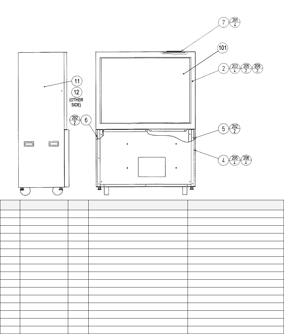
119
7.3. ORP-1000UK ASSY PTV
ITEM PART NO. QTY DESCRIPTION COMPONENT REF.
4 NCR-0600UK 1 ASSY FRONT PANEL
5 DYN-0501 1 PANEL MOUNT BRKT L
6 DYN-0502 1 PANEL MOUNT BRKT R
8 SPX-0532UK 1 PROTECT SCREEN PTV (101)-1
9 SPX-0533UK 2 RETAINING BRKT HORIZ PTV (8)-2
10 ORP-1012UK 1 STICKER PTV SIDE R
12 ORP-1013UK 1 STICKER WEB RANKING (2)-1
101 200-5788-31 1 PROJECTION DSPL T 50TYPE 31K
202 000-P00516-W 4 M5X16 MSCR PAN W/FS PAS (5)-2,(6)-2
203 000-T00520-0B 4 M5X20 MSCR TH BLK (2)-4
204 000-P00410-W 1 M4X10 MSCR PAN W/FS PAS EARTH-2
205 000-T00525-0B 6 M5X25 MSCR TH BLK (2)-2,(4)-4
206 068-552016-0B 6 M5 WSHR 20OD FLT BLK (2)-2,(4)-4
207 050-F00400 1 M4 NUT FLG SER PAS EARTH-1
208 000-F00412 4 M4X12 MSCR CSK PAS (2)-4
301 ORP-60048UK 1 WH PTV EARTH LINK
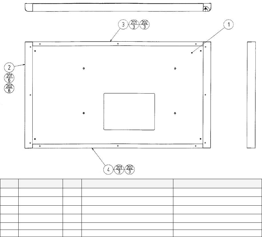
120
7.4. NCR-0600UK ASSY FRONT PANEL
ITEM PART NO. QTY DESCRIPTION COMPONENT REF.
1 NCR-0601UK 1 FRONT PANEL
2 EZT-0603 2 SIDE BRKT
3 EZT-0604 1 BRKT UPPER
4 EZT-0605 1 BRKT LOWER
201 068-552016 12 M5 WSHR 20OD FLT PAS (2)-6,(3)-3,(4)-3
202 050-F00500 12 M5 NUT FLG SER PAS (2)-6,(3)-3,(4)-3

121
7.5. ORP-2000UK ASSY MAIN CABI
ITEM PART NO. QTY DESCRIPTION COMPONENT REF.
1 ORP-2050UK 1 ASSY FRONT CABI
2 ORP-2350UK 1 ASSY REAR CABI
3 ORP-3020UK 1 ASSY BASE BOX
4 ORP-4100UK 1 ASSY AMP BD
5 ORP-4200UK 1 ASSY ELEC BD MOVE TO 2050
9 ORP-2400UK 1 ASSY SEAT
11 RAL-2007 1 RUBBER HOLDER R TWIN (9)-1
12 RAL-2008 1 RUBBER HOLDER L TWIN (9)-1
58 ORP-3000UK 1 ASSY FRAME BASE
213 030-000820-S 8 M8X20 BLT W/S PAS (3)-8
219 060-F00800 14 M8 WSHR FORM A FLT PAS (1)-6,(3)-8
232 030-000820-SB 5 M8X20 BLT W/S BLK (9)-5
238 068-852216-0B 5 M8 WSHR 22OD FLT BLK (9)-5
242 000-T00440-0B 1 M4X40 MSCR TH BLK (4)-1
243 068-441616 1 M4 WSHR 16OD FLT PAS (4)-1
244 030-000830-S 6 M8X30 BLT W/S PAS (1)-6
245 050-F00600 2 M6 NUT FLG SER PAS (1)-2
246 060-F00600 9 M6 WSHR FORM A FLT PAS (1)-2,(2)-6,(5)-1
247 030-000630-S 6 M6X30 BLT W/S PAS (2)-6
248 030-000620-S 1 M6X20 BLT W/S PAS (5)-1

122
7.6. ORP-2050UK ASSY FRONT CABI
ITEM PART NO. QTY DESCRIPTION COMPONENT REF.
1 ORP-2051UK 1
COCKPIT CABI
4 ORP-2070UK 1
ASSY AC UNIT
5 ORP-2054UK 1
CONTROL PANEL BRKT REF FRI-1202UK
8 FRI-1203 1
HANDLE COLLAR
9 FRI-2550 1 ASSY HANDLE MECHA
10 FRI-2600 1
ASSY PADDLE SHIFT TWIN
11 SPG-2001 1
STEERING WHEEL
12 FRI-2002 1
EMBLEM
13 SPG-2039 1
SPACER RING (11)-1
15 FRI-2055 2
BOSS COVER
16 DYN-1270 1
STOPPER KEY (9)-1
29 ORP-2019UK 1
COVER KNEE
30 ORP-2031-EUK 1
STICKER CABI UPPER L
31 ORP-2031-FUK 1
STICKER CABI UPPER R
32 ORP-2031-AUK 1
STICKER CABI MID BASE BOX L
33 ORP-2031-BUK 1
STICKER CABI MID BASE BOX R
34 ORP-2031-CUK 1
STICKER CABI REAR BASE BOX L
35 ORP-2031-DUK 1
STICKER CABI REAR BASE BOX R
36 ORP-2026UK 1
BULK BOARD BRKT
37 ORP-2027UK 1
CONTROL PANEL COVER R REF FRI-1201-02
38 ORP-2028UK 1
ASSY BULK BOARD COVER
39 SPG-2029-A-YE 1 CONPANE SIDE COVER L BLANK YELLOW FERRARI LOGO ON
SIDE?
40 SPG-2030-AUK 1
CONPANE SIDE COVER R BLANK UK
*1 SPG-2030-A-YE 1
CONPANE SIDE COVER R BLANK YELLOW
41 SPG-2031-A-YE
1 BONNET COVER BLANK YELLOW
42 ORP-2055UK 1 JOINT PLATE REAR
43 ORP-2056UK 1 JOINT PLATE FRONT L
44 ORP-2057UK 1 JOINT PLATE FRONT R
45 ORP-2035UK 1 LENS FLASH SPG-2035
46 ORP-2036UK 2 HOLDER PIN SPG-2036
47 ORP-2037UK 1 METER LAMP BRKT LAMP?
50 ORP-2031-GUK 1 STICKER CABI UPPER R DOOR
51 ORP-2058UK 1 COVER COCKPIT LOWER L
52 ORP-2059UK 1 COVER COCKPIT LOWER R
53 ORP-2060UK 1 BONNET BRKT L
54 ORP-2061UK 1 BONNET BRKT R
55 ORP-2062UK 1 FOOTWELL BRKT R
56 ORP-2063UK 1 PLATE INSTR
58 ORP-2065UK 2 SPEAKER MTG BRKT
59 ORP-2066UK 1 COIN TOWER CABI PLATE
60 ORP-2067UK 1 HUB HOLDER PLATE
61 ORP-2068UK 1 CONTROL PANEL SUPP L
69 ORP-2080UK 1 ASSY CTRL PANEL COVER F
70 ORT-4552UK 1 HUB HOLDER BRKT MAGNETIC ~ REVERT
BACK
71 CFB-4002UK 1 OUTLET BRKT

123
Contd.
ITEM PART NO. QTY DESCRIPTION COMPONENT REF.
73 DP-1167UK 1 TNG LKG UK (110)-1
102 280-A01200-A 4 ROUTER TWIST D12 ADH
103 280-A02000-A 1 ROUTER TWIST D20 ADH
104 280-A02048-PM 2 ROUTER TWIST D20 SO4.8 PAN
LG
106 580027 2 SPEAKER-ELIPTICAL-8OHMS 15W (59)-2
108 601-11071-IS 1 SW HUB PCI FX-08IS
109 601-6851UK 1 USA MAINS SOCKET CN06442 (71)-1
110 220-5575UK 1 LOCK
111 253-5460-01 3 AIR VENT BLACK
201 000-P00412-W 8 M4X12 MSCR PAN W/FS PAS (106)-8
203 000-T00412-0C 23 M4X12 MSCR TH CRM (39)-6,(40)-11,(41)-6
206 000-P00320-W 4 M3X20 MSCR PAN W/FS PAS (47)-4
207 000-T00412-0B 18 M4X12 MSCR TH BLK (37)-9,(38)-4,(56)-3,(69)-2
208 000-F00410 2 M4X10 MSCR CSK PAS (38)-2
209 068-441616-0C 7 M4 WSHR 16OD FLT CRM (39)-2,(40)-5
210 030-000620-S 5 M6X20 BLT W/S PAS (5)-2,(36)-3
212 060-F00600 15 M6 WSHR FORM A FLT PAS (36)-3,(51)-2,(52)-2,(55)-4,(59)-4
219 060-F00800 6 M8 WSHR FORM A FLT PAS (9)-6
226 000-P00512-W 2 M5X12 MSCR PAN W/FS PAS (47)-2
230 020-000820 1 M8X20 BLT PAS (11)-1 (USE ANAEROBIC
RETAINER)
232 060-S00800 5 M8 WSHR SPR PAS (9)-4,(11)-1
233 050-U00800 4 M8 NUT NYLOK PAS (9)-4
234 FAS-200013 4 M4X16 SKT CAP CRM (12)-4
238 050-F00400 6 M4 NUT FLG SER PAS (45)-2,(46)-2,EARTHS - 2
239 000-T00408-0B 8 M4X8 MSCR TH BLK (15)-8
240 028-A00410-P 1 M4X10 GSCR SKT CUP P (10)-1
241 050-F00400 2 M4 NUT FLG SER PAS (70)-2
242 012-P03512-F 16 N6X1/2" S/TAP FLG PAS (60)-4,(61)-10,(71)-2
243 000-T00440-0B 6 M4X40 MSCR TH BLK (1)-6 (DOORS)
244 030-000630-S 13 M6X30 BLT W/S PAS (5)-2,(51)-2,(52)-2,(55)-3,(59)-4
245 030-000820-S 2 M8X20 BLT W/S PAS (9)-2
246 000-T00530-0B 15 M5X30 MSCR TH BLK (4)-4,(29)-3,(51)-4,(52)-4
247 030-000820-SB 8 M8X20 BLT W/S BLK (42)-4,(43)-2,(44)-2
248 030-000830-SB 4 M8X20 BLT W/S BLK (42)-4
249 000-T00512-0B 4 M5X12 MSCR TH BLK (43)-2,(44)-2
250 000-F00416 2 M4X16 MSCR CSK (45)-2
251 068-441616 2 M4 WSHR 16OD FLT PAS (45)-2
252 000-F00420 2 M4X20 MSCR CSK (46)-2
253 000-P00420-W 10 M4X20 MSCR PAN W/FS PAS (53)-3,(54)-3,(58)-4
254 030-000650 1 M6X50 BLT PAS (55)-1

124
Contd.
ITEM PART NO. QTY DESCRIPTION COMPONENT REF.
255 000-T00616-0B 2 M6X16 MSCR TH BLK (56)-2
256 060-F00600-0B 2 M6 WSHR FORM A FLT BLK (56)-2
257 060-F00400-0B 9 M4 WSHR FORM A FLT BLK (1)-6,(56)-3
258 000-T00420-0B 12 M4X20 MSCR TH BLK (110)-4x3
301 ORP-60012UK 1 WH HANDLE EXT
302 ORP-60013UK 1 WH VTS EXT
303 ORP-60014UK 1 WH BUTTON ASSY EXT
304 ORP-60027UK 1 WH AUDIO VOLUME EXT
305 ORP-60029UK 1 WH AMP SPKRS B
306 ORP-60030UK 2 WH AMP SPKRS C
307 ORP-60034UK 1 WH FL LAMP 240V
308 ORP-60035UK 1 WH FL 240 EXT
309 ORP-60041UK 1 WH XFMR EXT
310 ORP-60045UK 1 WH CONN BRD EXT A
312 ORP-60049UK 1 WH MULTI EARTH

125
7.7. ORP-2070UK ASSY AC UNIT
ITEM PART NO. QTY DESCRIPTION COMPONENT REF.
1 ORP-2071UK 1 AC BRKT UK
101 EP1379 1 FILTER EMI 10A ARCOTRONICS
102 EP1302 1 EUROSOCKET FUSED 1OA
250Vac
103 EP1303 1 SWITCH ROCKER DPST 10A
250Vac
104 514-5078-5000 1 FUSE 5X20 CERAMIC SB 5000mA
105 310-5029-D508 0.05 HEAT SHRINK SLEEVING 50.8DIA OVER ITEM 102(50MM OVER
SOCKET)
106 421-6595-5000-T 2 STICKER FUSE 5000mA TYPE T NEXT TO IEC INLET + FUSE
HOLDER
107 LB1096 1 STICKER PROTECTIVE EARTH NEXT TO EARTH STUD
201 060-S00300 4 M3 WSHR SPR PAS (101)-4
202 060-F00300 4 M3 WSHR FORM A FLT PAS (101)-4
203 000-P00310 4 M3X10 MSCR PAN PAS (101)-4
204 050-F00400 3 M4 NUT FLG SER PAS (INSIDE EARTH)-2,(OUTSIDE)-1
301 ORP-60033UK 1 WH AC OUT PRIMARY FROM FILTER TO XFMR
302 600-9100-44K 1 WIRE HARN EARTH 1000mm
M4/M4 K
AC BRKT TO NCR-1020

126
7.8. ORP-2027UK CONTROL PANEL COVER R
ITEM PART NO. QTY DESCRIPTION COMPONENT REF.
1 SPG-2027-AUK 1 CTRL PNL COVER R BLANK UK
*1 SPG-2027-A-BL 1 CTRL PNL COVER R BLANK BLACK
2 ORP-2027-BUK 1 METER PANEL A
3 ORP-2027-CUK 1 METER PANEL B
201 008-T00412-0C 4 M4X12 TMP PRF CRM (2,3)-4
202 050-F00400 4 M4 NUT FLG SER PAS (2,3)-4
203 060-F00400 4 M4 WSHR FORM A FLT PAS (2,3)-4

127
7.9. ORP-2028UK ASSY BULK BOARD COVER
ITEM PART NO. QTY DESCRIPTION COMPONENT REF.
1 SPG-2028UK 1 BULK BOARD COVER UK machine
*1 SPG-2028 1 BULK BOARD COVER
*2 SPG-2028-BUK 1 PLATE MTG BUTTON PLATE
4 ORT-2100 1 ASSY SW PLATE
201 008-T00412-0B 4 M4X12 TMP PRF TH BLK (2)-2,(3)-2
202 000-T00412-0C 4 M4X12 MSCR TH CRM (4)-4
203 050-U00400 4 M4 NUT NYLOK PAS (2)-2,(3)-2
204 060-F00400 4 M4 WSHR FORM A FLT PAS (2)-2,(3)-2

128
7.10. ORP-2080UK ASSY CTRL PANEL COVER F
ITEM PART NO. QTY DESCRIPTION COMPONENT REF.
1 SPG-2054-AUK 1 CTRL PANEL COVER F UK
*1 SPG-2054-BL 1 CTRL PANEL COVER F BLACK
2 ORP-2064UK 1 BOX REAR CRTL PNL COVER
3 ORP-2081UK 2 SPACER BOX REAR BETWEEN (1)&(2)
201 050-F00400 4 M4 NUT FLG SER PAS
202 068-441616 4 M4 WSHR 16OD FLT PAS

129
7.11. ORP-2350UK ASSY REAR CABI
ITEM PART NO. QTY DESCRIPTION COMPONENT REF.
1 ORP-2351UK 1 ASSY CABI REAR
2 ORP-2032UK 1 REAR FAIRING
3 ORP-2353UK 1 BRKT SUPT NUM PL
4 ORP-2354UK 1 BRKT MTG LED STRIP
5 ORP-2355UK 2 BRKT MTG TAILPIPE
6 ORP-2363UK 1 LED BRAKE LIGHT
7 ORP-2364UK 2 TAILPIPE EXHAUST
9 ORP-2366UK 1 STICKER TAIL LIGHT CLUSTER
10 ORP-2367UK 1 NUMBER PLATE
11 ORP-2368UK 2 BRKT BULB MTG
12 ORP-2365-AUK 4 REAR LIGHT TOP
13 ORP-2365-BUK 4 REAR LIGHT BASE
14 ORP-2369UK 1 STICKER REAR FAIRING LOWER
15 ORP-2370UK 1 BRKT CONN PNL MOUNT
16 ORP-2371UK 2 BRKT REINFORCE
101 400-5421-03012 1 SW REGU LCA30S-12
102 ORP-A838-
001UK
1 ASSY BRAKE LIGHTCONT
103 220-5575UK 2 LOCK
104 ORP-2372UK 2 CAM CRKD 9 L34 BATON 690-
ZB34
201 000-T00512-OC 4 M5X12 MSCR POSI TH CRM ?(2)-4
202 000-T00630-0B 3 M6X30 MSCR TH BLK (2)-3
203 000-T00540-0C 2 M5X40 MSCR TH CRM (2)-2
204 008-T00625-0C 3 M6X25 TMP PRF TH CRM (2)-3
205 000-T00620-0C 6 M6X20 MSCR TH CRM (2)-6
206 000-P00612-W 8 M6X12 MSCR PAN W/FS PAS (3)-2,(5)-6
207 000-P00408-W 1 M4X8 MSCR PAN W/FS PAS (6)-1
208 008-T00408-0C 2 M4X8 TMP PRF TH CRM (10)-2
209 000-P00420-W 6 M4X20 MSCR PAN W/FS PAS (11)-6
210 008-T00420-0B 8 M4X20 TMP PRF TH BLK (12,13)-8
211 000-P00412-W 4 M4X12 MSCR PAN W/FS PAS (15)-4
212 030-000620-S 4 M6X20 BLT W/S PAS (16)-4
213 060-F00600-0B 3 M6 WSHR FORM A FLT BLK (2)-3
214 060-F00600 1 M6 WSHR FORM A FLT PAS (2)-1
215 050-F00600 2 M6 NUT FLG SER PAS (4)-2
216 068-652516 2 M6 WSHR 25OD FLT PAS (4)-2

130
Contd.
ITEM PART NO. QTY DESCRIPTION COMPONENT REF.
217 068-441616-0C 2 M4 WSHR 16OD FLT CRM (10)-2
218 050-U00400 8 M4 NUT NYLOK PAS (12,13)-8
219 060-F00400 8 M4 WSHR FORM A FLT PAS (12,13)-8
220 012-P00325 8 N4X1" S/TAP PAN PAS (101)-4,(102)-4
301 ORP-60037UK 1 WH BRAKE LIGHTS A
302 ORP-60038UK 1 WH BRAKE LIGHTS POWER
303 ORP-60039UK 1 WH BRAKE LIGHTS B
304 ORP-60051UK 1 WH BRAKE LAMPS

131
7.12. ORP-3020UK ASSY BASE BOX
ITEM PART NO. QTY DESCRIPTION COMPONENT REF.
1 ORP-3021UK 1 BASE BOX INC . DOOR + HINGE
2 ORP-2260UK 1 FLOOR CENTRE ASSY
3 ORP-4000UK 1 ASSY MAIN BD
8 DP-1167UK 1 TNG LKG UK (101)-1
9 ORP-3022UK 1 PNL MOUNT BRKT
10 FN1012 1 MESH GUARD METAL 120mm FAN (102)-1
101 220-5575UK 1 LOCK
102 260-0011-02 1 AXIAL FLOW FAN AC100V 50-60Hz AIRFLOW OUT
103 OS1195 4 RIVET SNAP MOSS SR1811 (10)-4
104 280-A02048-PM 3 ROUTER TWIST D20 SO4.8 PAN LG (1)-3
105 280-A01248-PM 2 ROUTER TWIST D12 SO4.8 PAN MED (1)-2
201 000-T00616-0B 4 M6X16 MSCR TH BLK (2)-4
202 012-HB0512 4 N10X1/2" S/TAP HEX B PAS (102)-4
203 060-F00500 4 M5 WSHR FORM A FLT PAS (102)-4
204 050-F00400 3 M4 NUT FLG SER PAS (9)-2,EARTH
205 000-T00430-0B 2 M4X30 MSCR TH BLK (1)-2
206 068-441616-0B 2 M4 WSHR 16OD FLT BLK (1)-2
207 030-000620-S 1 M6X20 BLT W/S PAS (3)-1
208 068-652516 1 M6 WSHR 25OD FLT PAS (3)-1
209 008-T00430-0B 1 M4X30 TMP PRF TH BLK LOCK
301 600-7141-250 1 CABLE JVS TYPE A-B 250CM
302 600-7009-3000UK 1 ASSY RGB CA D-SUB 15P 3000MM ?
303 ORP-6001UK 1 ASSY CABLE RUN
304 600-7269-0200 1 ASSY LAN CABLE 0200CM long enough?

132
7.13. ORP-2260UK FLOOR CENTRE ASSY
ITEM PART NO. QTY DESCRIPTION COMPONENT REF.
1 ORP-2261UK 1 FLOOR CENTRE
2 SPG-2200 1 ASSY ACCEL & BRAKE
4 SPG-2222UK 1 ANTI FINGER TRAP PLATE LEFT
5 SPG-2223UK 1 ANTI FINGER TRAP PLATE RIGHT
6 SPG-2224UK 1 PEDAL GASKET UNDER (2)-1
7 FRI-2201 1 FOOT REST FRI
201 068-852216-0B 8 M8 WSHR 22OD FLT BLK (2)-4,(7)-4
202 030-000820-SB 4 M8X20 BLT W/S BLK (2)-4
203 050-U00800 4 M8 NUT NYLOK PAS (7)-4
301 ORP-60011UK 1 WH BRAKE ACC EXT

133
7.14. ORP-4000UK ASSY MAIN BD
ITEM PART NO. QTY DESCRIPTION COMPONENT REF.
1 ORP-4001UK 1 MAIN BD BASE
2 843-0011D-02 1 ASSY CASE BOX ORP EXP
4 105-5435 1 GD DRIVE BRKT STD
5 LB1111 1 STICKER PLEASE RECYCLE
6 610-0617 1 GD-ROM DRIVE UNIT NAOMI SHIP BOX WITH MACHINE
7 610-0652-0011 1 GD SOFT ORP
101 400-5443-01 1 SW REGU FOR CHIHIRO VA
106 280-A00964-WX 6 ROUTER TWIST D09 SO6.4 WOOD X size?
107 LB1101 1 STICKER WARNING BATTERY GAME BD
201 000-P00416-W 11 M4X16 MSCR PAN W/FS PAS (2)-4,(4)-3,(101)-4
203 012-P00410-F 4 N8X3/8" S/TAP FLG PAS (6)-4
307 600-7247-500 1 CABLE SCSI ST-L TYPE2 500MM
308 600-7159-039 1 WIRE HARN JVS PWR 039CM
309 HDT-60100UK 1 WH POWER GD ROM
310 ORP-60006UK 1 WH MIDI B
311 ORP-60016UK 1 WH AUDIO
312 ORP-60020UK 1 WH I/O BD PWER EXT B
313 ORP-60021UK 1 WH SWITCH MODE
314 ORP-60050UK 1 WH BLC SIGNAL

134
7.15. ORP-6001UK ASSY CABLE RUN
ITEM PART NO. QTY DESCRIPTION COMPONENT REF.
301 ORP-60018UK 1 WH I/O BRD PWR EXT
302 ORP-60036UK 1 WH SIGNAL BRAKE LIGHT
303 ORP-60017UK 1 WH AUDIO EXT
304 ORP-60019UK 1 WH MIDI EXT
305 ORP-60047UK 1 WH SPKR REAR EXT B
306 ORP-60004UK 1 WH AC SUB CABI EXT
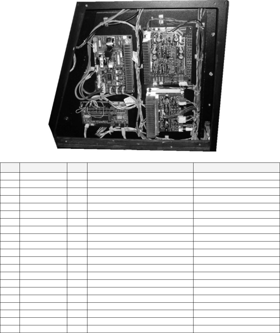
135
7.16. ORP-4100UK ASSY AMP BD
ITEM PART NO. QTY DESCRIPTION COMPONENT REF.
1 ORP-4101UK 1 WOODEN AMP BD BASE
3 838-13578 1 PWR AMP 2CH & MIXER
5 837-13551-92 1 I/O CONTROL BD FOR JVS
101 838-13616 1 AUDIO POWER AMP 2CH
102 838-14174 1 SERVO MOTOR DRIVE BD MIDI
105 211-5305 2 C JMPR SCKT (IMSA-9206H-GF) (3)-2
111 280-A01264-WX 11 ROUTER TWIST D12 SO6.4 WOOD X AMP BD BASE
112 280-A00964-WX 4 ROUTER TWIST D09 SO6.4 WOOD X AMP BD BASE
203 012-P00325 16 N4X1" S/TAP PAN PAS (3)-4,(5)-4,(101)-4,(102)-4
301 ORP-60005UK 1 WH MIDI A
302 ORP-60007UK 1 WH 100V EXT MIDI
303 ORP-60008UK 1 WH POWER I/O BRD
304 ORP-60009UK 1 WH I/O BRD A
305 ORP-60010UK 1 WH I/O BRD A/D
306 ORP-60022UK 1 WH AUDIO A
307 ORP-60023UK 1 WH AMPS PWR IN
309 ORP-60025UK 1 WH AUDIO VOLUMES
310 ORP-60026UK 1 WH AMP SPKRS
311 ORP-60028UK 1 WH AMP SPKRS A
312 FRI-61030UK 1 WH EXT MOTOR A
313 TOF-60011UK 1 WH EXT ENCODER A
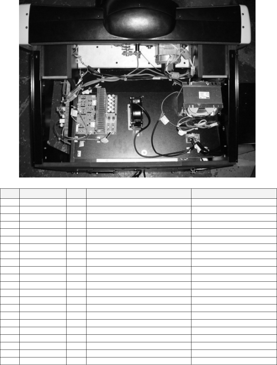
136
7.17. ORP-4200UK ASSY ELEC BD
ITEM PART NO. QTY DESCRIPTION COMPONENT REF.
1 ORP-4201UK 1 WOODEN BASE ELEC
2 ORP-4202UK 1 BASE XFMR
3 ORP-4203UK 1 COVER XFMR
4 838-13142 1 BASS AMP
5 SRT-1203UK 1 FAN BRKT UK
6 FN1012 3 MESH GUARD METAL 120mm FAN (101)-3
7 JPT-4102UK 1 FAN BRKT
101 260-0011-02 2 AXIAL FLOW FAN AC100V 50-60Hz AIRFLOW TOWARDS MOTOR
102 560-5430UK 1 XFMR NCR DX
105 838-11856CE-02 1 CONNECT BD W/FUSE 6.3A CE
107 354081 11 TWIST LOK BHKL-450-4 HOLES IN BASE
108 354083 10 (A)TWIST N LOK BHKL-750-4 HOLES IN BASE
109 280-A00964-WX 12 ROUTER TWIST D09 SO6.4 WOOD X HOLES IN BASE
111 290190 9 TAPE-FOAM-20MM X 4.50MM -101
201 012-P00325 14 N4X1" S/TAP PAN PAS (4)-8,(103)-4,(105)-2
203 000-P00416-W 4 M4X16 MSCR PH W/FS PAS (102)-4
206 068-441616 4 M4 WSHR 16OD FLT PAS (102)-4
302 ORP-60001UK 1 WH CONN BRD
303 ORP-60002UK 1 WH CONN BRD B
305 ORP-60003UK 1 WH XFMR SECONDARY
306 ORP-60043UK 1 WH AC EXT
307 ORP-60044UK 1 WH XFMR 100V
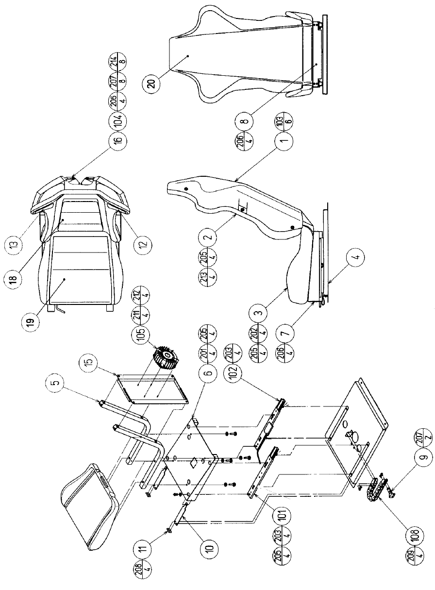
137
7.18. ORP-2400UK ASSY SEAT

138
ITEM PART NO. QTY DESCRIPTION COMPONENT REF.
1 ORP-2401-AUK 1 SEAT REAR COVER BLANK NCR-2401-AUK check type
2 SPG-2401-AUK 1 UPPER SEAT BLANK
3 SPG-2402-AUK 1 LOWER SEAT BLANK
4 ORP-2404UK 1 SEAT BASE STC-1603/NCR-2405/SPG-2403
5 SRT-2402UK 2 SEAT FRAME cf STC-1604
6 NCR-2405 1 SEAT SLANT TRAY STC-1606
7 FRI-3307 1 FRONT TRAY COVER STC-1613
8 NCR-2406 1 REAR TRAY COVER STC-1610
9 FRI-3309 1 CABLE BEAR BRKT
10 STC-1612 2 PROTECT RUBBER
12 STC-1608 1 SPEAKER NET L
13 STC-1609 1 SPEAKER NET R
15 DUT-2205 1 SHAKER BASE REAR
16 STC-1607 2 SP MOUNT BRKT
18 SPG-2401-BUK 1 UPPER SEAT INSERT (2)-1
19 SPG-2402-BUK 1 LOWER SEAT INSERT (4)-1
20 ORP-1603-BUK 1 STICKER SEAT BACK
21 SRT-2409 2 SHOULDER PAD INBETWEEN SPKR NETS &
SEAT
101 601-9059-91 1 SEAT RAIL L
102 601-9060-91 1 SEAT RAIL R
103 280-5297 6 SCRIVET 8 1K31 (1)-6
104 130-5162-01 2 GULL BOX SPEAKER
105 130-5172 1 BASS SHAKER (15)-1
106 280-K02529-WX 18 DRIVE FASTENER 25FH 24L 7.9DIA (18)-8,(19)-10
108 601-6981-009 1 CABLE BEAR L=009
109 280-A00900-A 4 ROUTER TWIST D9 ADH
201 030-000816-S 4 M8X16 BLT W/S PAS (6)-4
202 030-000850-SB 8 M8X50 BLT W/S BLK (2)-4,(3)-4
203 050-U00800 8 M8 NUT NYLOK PAS (101)-4,(102)-4
205 068-852216 20 M8 WSHR 22OD FLT PAS (2,3,6,101,102)-4EA
206 000-T00408-0B 8 M4X8 MSCR TH BLK (7)-4,(8)-4
207 000-P00410-W 13 M4X10 MSCR PAN W/FS PAS (9)-2,(104)-8,(EARTHS)-3
209 000-T00616-0B 4 M6X16 MSCR TH BLK (108)-4
211 060-F00400 4 M4 WSHR FORM A FLT PAS (105)-4
212 050-U00400 4 M4 NUT NYLOK PAS (105)-4
214 012-P03512-F 8 N6X1/2" S/TAP FLG PAS (16)-8
216 FA400014 6 A NO.8X5/8" POZI FLANGE S/T SW (12)-3,(13)-3
301 ORP-60031UK 1 WH SPKR REAR EXT
302 ORP-60032UK 1 WH SPEAKER REAR

139
7.19. ORP-3000UK ASSY FRAME BASE
ITEM PART NO. QTY DESCRIPTION COMPONENT REF.
1 ORP-3001UK 1 FRAME BASE
101 601-5699UK13-01 6 LEG ADJ M16X130 1L/NUT
102 MA1019 4 CASTER 75
202 030-000620-S 16 M6X20 BLT W/S PAS (102)-16
203 060-F00600 16 M6 WSHR FORM A FLT PAS (102)-16

140
7.20. ORP-INST-D ASSY INSTALLATION KIT ORP DX
ITEM PART NO. QTY DESCRIPTION COMPONENT REF.
1 ORP-3100UK 1 ASSY COIN CHUTE TOWER WRAPPED & PLACED IN
FOOTWELL
2 ORP-0500UK 1 ASSY BILLBOARD
4 NCR-0002 2 JOINT BRKT CENTER
6 ORP-0512UK 1 POP PANEL ORP DX
7 ORP-0513UK 1 POP BRKT
8 ORP-3011UK 1 TOWER BASE
9 ORP-0001UK 1 JOINT BRKT FRONT CABI L
10 ORP-0002UK 1 JOINT BRKT FRONT CABI R
20 422-0932DUK 1 PLAY INSTR SH ORP DX MULTI
23 440-CS0186UK 1 STICKER C EPILEPSY MULTI
201 030-000830-SB 14 M8X30 BLT W/S BLK (4)-8,(8)-2,(9)-2,(10)-2
202 068-852216-0B 14 M8 WSHR 22OD FLT BLK (4)-8,(8)-2,(9)-2,(10)-2
203 060-F00800 3 M8 WSHR FORM A FLT PAS (1)-3
207 060-F00600 2 M6 WSHR FORM A FLT PAS (8)-2
209 050-F00600 2 M6 NUT FLG SER PAS (8)-2
212 030-000860-SB 3 M8X60 BLT W/S BLK (1)-3
213 000-P00516-WB 2 M5X16 MSCR PAN W/FS BLK (2)-2
214 000-P00412-WB 6 M4X12 MSCR PAN W/FS BLK (6)-3,(7)-3
215 068-441616-0B 6 M4 WSHR 16OD FLT BLK (6)-3,(7)-3
401 PK0369 1 INST KIT BOX ORP DX
402 OS1019 3 SELF SEAL BAG 9X12.3/4 BRACKETS, BOLTS & MANUALS
408 509-5387 1 SW MICRO TYPE (AH71557K) SPARE - PADDLE SHIFTER
409 220-5484 1 VOL CONT B-5K OHM SPARE - HANDLE MECHA
411 600-7269-0500 1 LAN CABLE 500CM
412 420-6830-01UK 1 SERVICE MANUAL ORP DX
413 540-0006-01 1 WRENCH M4 TMP PRF
416 540-0007-01 1 WRENCH M5 TMP PRF
417 540-0009-01 1 WRENCH M8 TMP PRF
418 SAECE-xxx 1 DECLARATION OF CONFORMITY DECLARATION OF CONFORMITY
ORPD

141
7.21. ORP-0500UK ASSY BILLBOARD
ITEM PART NO. QTY DESCRIPTION COMPONENT REF.
1 SPG-0501-YE 1 BILLBOARD SIDE COVER L YELLOW
2 SPG-0502-YE 1 BILLBOARD SIDE COVER R YELLOW
3 ORP-0503UK 1 BILLBOARD BOX
6 ORP-0506UK 1 UPPER SASH
8 ORP-0508UK 1 HOLE LID BILLBOARD
9 ORP-0510UK 1 BILLBOARD PLATE ORP
*1 ORP-0510-AUK 1 BILLBOARD PLATE BLANK
10 ORP-0511UK 1 STICKER BILLBOARD F LOWER
101 390-5695-30-AUK 1 FL TRAY 100V 30W
102 LT1014 1 TUBE FL 30W 36" DIA25mm
104 LB1102 3 STICKER DANGEROUS VOLTAGE
105 LB1104 1 STICKER CAUTION, HOT SURFACE
106 421-7501-16 1 STICKER 110V 30W
107 280-A00900-A 5 ROUTER TWIST D9 ADH
201 000-T00408-0C 11 M4X8 MSCR TH CRM (1)-3,(2)-3,(6)-3,(8)-2
203 050-F00400 3 M4 NUT FLG SER PAS (101)-2,(EARTH)-1
204 000-F00412 4 M4X12 MSCR CSK PAS (1)-2,(2)-2
205 068-441616-0C 6 M4 WSHR 16OD FLT CRM (1)-3,(2)-3
206 068-441616 2 M4 WSHR 16OD FLT PAS (101)-2
207 000-P00412 2 M4X12 MSCR PAN PAS (TERRY CLIPS)
301 NCR-60420UK 1 WIRE HARN FL

142
7.22. ORP-3100UK ASSY COIN CHUTE TOWER
ITEM PART NO. QTY DESCRIPTION COMPONENT REF.
1 VTS-HOD-D 1 VTS BOARD HOD
2 ORP-3101UK 1 COIN CHUTE TOWER NCR-1101UK
4 DYN-0010UK 1 DENOMI PLATE
6 DUT-0302UK 1 COIN PATH PLATE
7 PP1087 1 BOX CASH FOR MINI DOOR
10 NCR-1103UK 1 CCT FLOOR
11 LB1103 2 STICKER CAUTION (10)-1,(2)-1 INSIDE TOP
AREA
201 000-P00408-W 11 M4X8 MSCR PAN W/FS PAS (1)-4,(6)-5,(10)-2
202 050-F00400 1 M4 NUT FLG SER PAS COINCHUTE
203 000-T00412-0B 4 M4X12 MSCR TH BLK (4)-4
301 ORP-60042UK 1 WH VTS
302 LM1006LOR 1 LOOM COIN MECH LAMP

143
8. APPENDIX A - ELECTRICAL SCHEMATIC
8.1. WIRE COLOURS
THE WIRE COLOUR CODE IS AS FOLLOWS:
A PINK
B SKY BLUE
C BROWN
D PURPLE
E LIGHT GREEN
Wires other than those of any of the colours listed above will be displayed by 2 alphanumeric characters:
1 RED
2 BLUE
3 YELLOW
4 GREEN
5 WHITE
7 ORANGE
8 BLACK
9 GREY
If the right hand side numeral of the code is 0, then the wire will be of a single colour shown by the left hand
side numeral (see the list above).
Note 1: If the right hand side alphanumeric is not 0, that particular wire has a spiral colour code. The left
hand side character shows the base colour and the right hand side one, the spiral colour.
[Example] 51------------- WHITE/RED = WHITE wire with RED stripes
Note 2: The character following the wire colour code indicates the size of the wire.
K: AWG18, UL1015
L: AWG20, UL1007
None AWG22, UL1007
8.2. ELECTRICAL SCHEMATIC
The following pages contain the electrical schematic for this machine.

144
LOCATE A3 SCHEMATIC DRAWING 1 HERE

145
LOCATE A3 SCHEMATIC DRAWING 2 HERE

146
LOCATE A3 SCHEMATIC DRAWING 3 HERE

147
SEGA AMUSEMENTS EUROPE LTD./ SEGA SERVICE CENTRE
Suite 3a
Oaks House
12 - 22 West Street
Epsom
Surrey
United Kingdom
KT18 7RG
Telephone: +44 (0) 1372 731820
Fax: +44 (0) 1372 731849
SEGA 2004
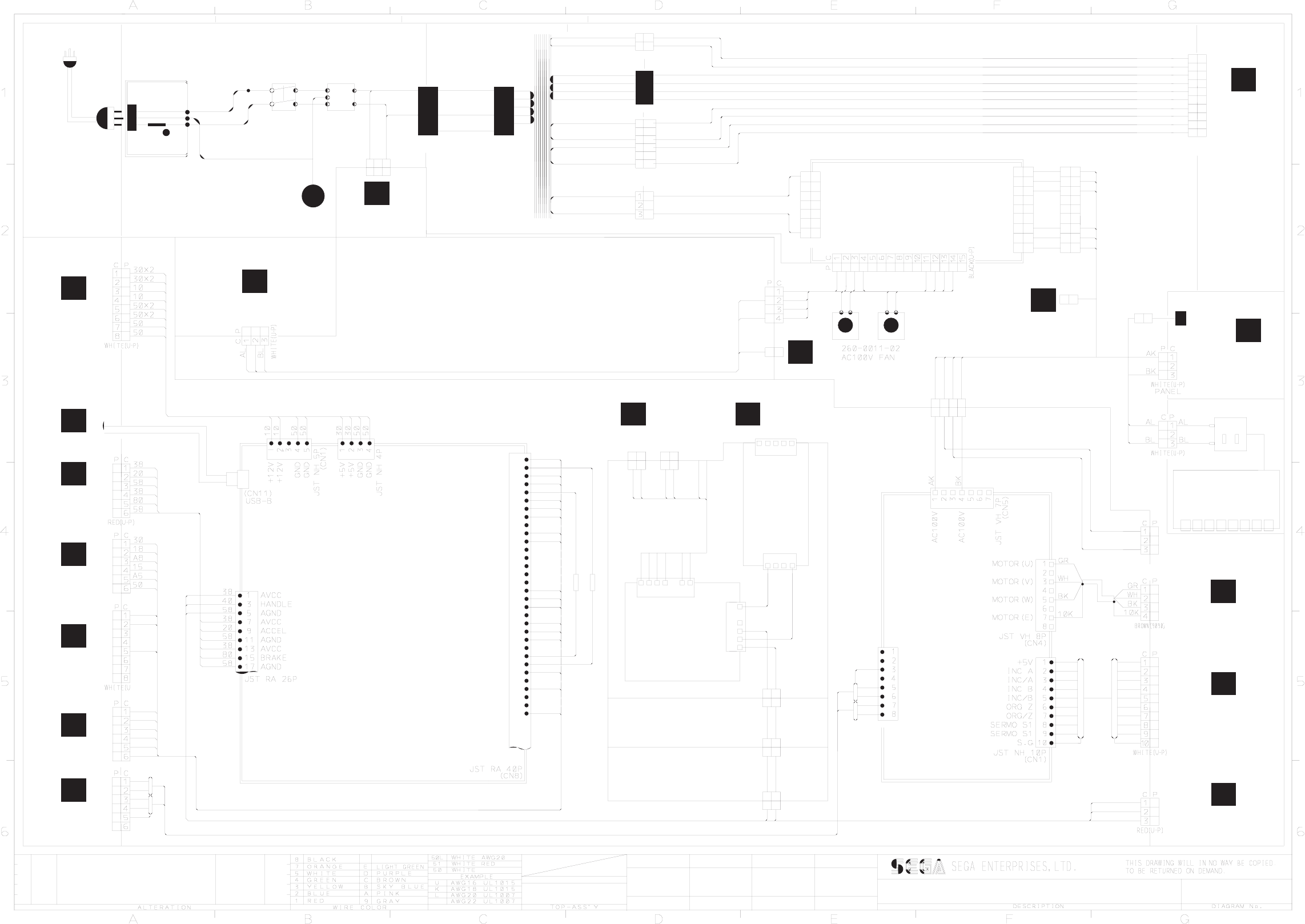
1
2
3
5
4
6
43K
43K
6
4
5
3
2
1
1
6
4
5
3
2
M&L
P C
SW 1109
SWITCH
EP 1302
514-5078-5000
5A T
C0L
20L
100V@5A
17V@2.1A
17V@2.1A
14V@6.3A
EP 1382
20L
C0L
P C
M&L
C0L
20L
230V
0V
NOISE FILTER
0V
0V
0V
0V
23V@9.6A
0V
0V
23V@9.6A
HUB
ORP-4000UK
ASSY MAIN BRD
ORP-60050UK
80
58
2
1
U-P
P C
30
30
30
30
30
50
50
50
50
50
15
91
B5
92
75
D5
32
30
30
18
A8
10
AL
AL
BL
BL
U P
C
1
1
C
U P
U P
P C
AL
AL
AL
BL
BL
BL
1
2
3
4
5
6
7
8
9
ORP-60038UK
GND
GND
I/P
+12V
O/P 3
O/P 2
O/P 1
+12V
+12V
+12V
VH
VH
VH
VH
ORP-60037UK
JP2
JP1
ORP-A838-001UK
BRAKE LIGHT
CONTROLER
10
10
10
50
50
50
1
2
3
4
5
6
10
80
50
58
X2
1
2
3
4
5
6
7
12V
12V
GND
GND
FG
AC100V
AC100V
400-5421-05012Y
PSU 12V 4.3A
LCA50S-12-Y
1
2
3
4
1
2
3
4
5
ORP-60036UK
(ORP-6001UK)
58
80
P C
U-P
2
1
1
2
U-P
P C
80 80
58
58
C P
C0L
20L
3
2
1
ORP-0000UK
ORP-60009UK
(CN7)
ORP-60010UK
ORP-60010UK
ORP-60009UK
ORP-60005UK
BK
AK
BK
AK
4
ORP-60004UK
30K
30K
30K
30K
OUTRUN 2 SPECIAL DLX
(SMPSU)
AK
BK
BK
AK P C
U-P
3
2
1
838-14174
DRIVER BD
CN 6
2x120 Ohm 1/4W Resistors
NH CN2
SG
80%
SG
60%
TXD
TXD_R
RXD
RXD_R
JST
CN1
CN2CN3
U-P BLK
1
2
3
4
5
6
7
8
9
1
2
3
4
5
6
7
838-11856CE-02
CONN BRD
AL
AL
AL
BL
BL
BL
U-P WHT
AL
AL
BL
BL
ORP-60002UK
AK
BK
U-P
600-7141-250
ORP-60008UK
91
92
50
1
AL
AL
AL
BL
BL
BL
43L
43L
601-11071-IS
SW HUB PCI FX-081S
12345678
601-8956-01
50
10 C P
U-P
2
1
1
2
U-P
C P
10
50
10
50
09/12/04
CW
ORP-4000UK
ASSY MAIN BD
ORP-3020UK
ASSY BASE BOX
A2
A1 43L
ORP-60048UK
ORP-60044UK
ORP-60043UKORP-60033UK
V POS: C5
T0 (3/3) T0 (2/3)
POS: C2
Z
POS: 4C
T0 (3/3)
X
50
WH
BK
WH
GR
WH
BL
WH
RE
PI
WH
RE
WH
SH
RE
T0 (2/3)
POS: C3
B
RE
U-P
SH
WH
RE
WH
1
2
3
4
7
10
11
12
13
14
17
19
20
21
22
23
24
25
26
27
41
43
45
46
49
50
51
53
54
55
56
59
SCHEM. 1/3
DRAWN CHKD
IEC INLET
TRANSFORMER
560-5430UK
ORP-60033UK
10K
90L
C0L
C0L
90L
U-P(RED)
4
2
1DK
1
2
3
C P
C P
U-P(YELL)
U-P
80K
70K
80K
70K
U-P
P C
3
1
2
80K
70K
70K
C0K
C0K
DK
90K
10K
ORP-60003UK
230V AC MAINS
10
50
50
D5
75
32
U-P
837-13551-92
I/O CONTROL
BRD FOR JVS
TOF-60011UK
PI
RE
WH
BL
WH
GR
WH
BK
WH
50
80K
90K
4
5
6
7
8
9
10
C P
C P
U-P
BLACK
T0 (2/3)
POS: G1
FRI-61030UK
R
M
L
K
POS: A4
T0 (3/3)
POS: A4
T0 (3/3)
POS: A5
T0 (3/3)
N
POS: A5
T0 (3/3)
A
C
Q
T0 (2/3)
POS: C1
POS: D2
T0 (3/3)
POS: G5
T0 (3/3)
E
T0 (2/3)
POS: C4
T0 (2/3)
POS: C6
S
F
POS: C2
T0 (2/3)
38
40
58
ORP-2070UK AC UNIT
OUTSIDE
WORLD
ORP-4100UK ASSY AMP BOARD
ORP-2050UK ASSY FRONT CABI
ORP-4200UK ASSY ELEC BRD
ORP-4100UK
ASSY AMP BD
ORP-3020UK
ASSY BASE BOX
NCR-2050UK FRONT CABI ASSY
EARTH
PLATE
43L ASSY PTV
PRIMARY
EARTH
ORP-60001UK
NOT
USED
ORP-60007UK
D
T0 (3/3)
POS: D3
ORP-60045UK
ORP-60007UK
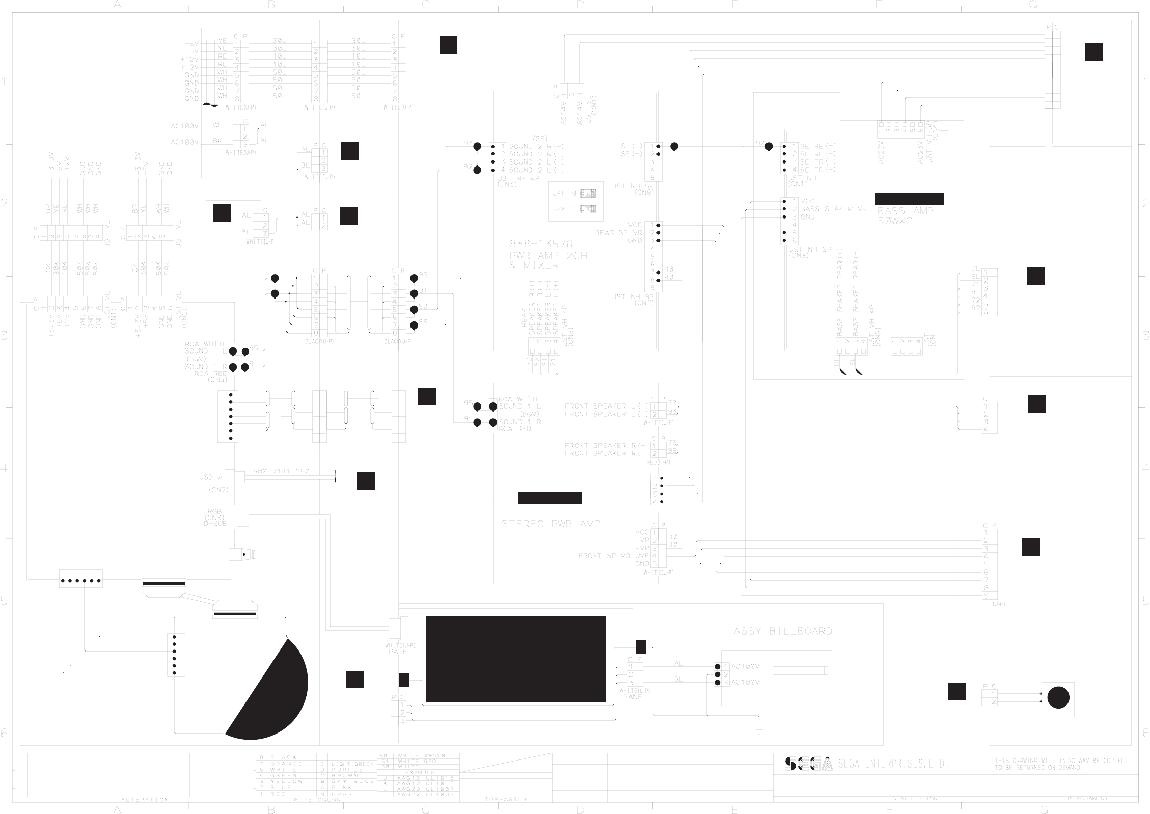
~
ORP-3020UK
ASSY BASE BOX
ORP-2050UK
ASSY FRONT CABI
P C
CW
09/12/04
600-7009-3000UK
ORP-4000UK
ASST MAIN BD
(GAME
BD FAN)
U P
U P
P C
P C
95
75
93
73
ORP-60028UK
U-P
ORP-60026UKORP-60026UK
ORP-60022UK
ORP-60019UK
(ORP-6001UK)
1
2
3
4
5
6
10
30
50
50
12V
5V
GND
GND
12V
12V
5V
5V
GND
GND
NH
HDT-60100UK
1
2
3
4
5
6
1
2
3
4
5
6
600-7247-500
610-0617
GD ROM
DRIVE UNIT
ORP-60016UK
600-7159-039
ORP-60018UK
(ORP-6001UK)
ORP-60017UK
(ORP-6001UK)
10
40
50
40
40
50
40
10
OUTRUN 2 SPECIAL DLX
843-0011D-02
ASSY CASE BOX ORP EXP
CN9
NH
1
2
3
4
5
6
TX/RX
LAN PORT C
1
2
3
4
5
6
7
ORP-60006UK
ORP-60020UK
ORP-60021UK
ORP-0000UK
400-5443-01
SW REGU FOR CHIHIRO
P C
JST VL
ORP-3020UK
ASSY BASE BOX
JST VL
M
(BACK
DOOR
FAN)
ORP-4100UK ASSY AMP BRD
S
POS: A6
TO (1/3)
BWH
RE
WH
SH
RE RE
SH
WH
RE
WH
WH
RE
WH
SH
RE
RE
SH
WH
RE
WH
PROJECTION DSPL T 50TYPE 31K
200-5788-31
EARTH
PLATE
PLATE
EARTH
43U
43U
2x43U
36" DIA 25mm
D-SUB
AC100V
AC17V
0V
0V
AC17V
0V
0V
BLUE
ORP-4100UK ASSY AMP BD
ORP-0500UK
ORP-1000UK ASSY PTV
ORP-4100UK
ASSY AMP BRD
A
TO (1/3)
POS: A2
TO (1/3)
POS: G3
F
TO (1/3)
POS: B2
E
TO (1/3)
POS: A3
TO (3/3)
POS: B1
J
TO (3/3)
POS: C1
H
R
P
390-5695-30-AUX
FL 30W
LT1014-FL UNIT
NCR-60420UK
U-P BLACK
ORP-60023UK
ORP-60024UK
ORP-60023UK
90K
C0K
90K
C0K
90K
C0K
C0K
90K
10K
DK
70K
80K
80K
70K
90K
C0K
C0K
90K
10K
DK
10
9
8
7
6
5
4
3
2
1
POS: G4
TO 3/3
ORP-60025UK
58
48
38
51
41
31
58
48
38
52
42
32
51
41
31
52
42
32
838-13616
JST VH
TO 1/3
POS: G1
SCHEM. 2/3
CHKDDRAWN
POS: E3
TO (1/3)
Y
Z
TO (3/3)
POS: XX
Y
TO (2/3)
POS: B2
CTF-60019UK
ORP-2050UK
ASSY FRONT CABI
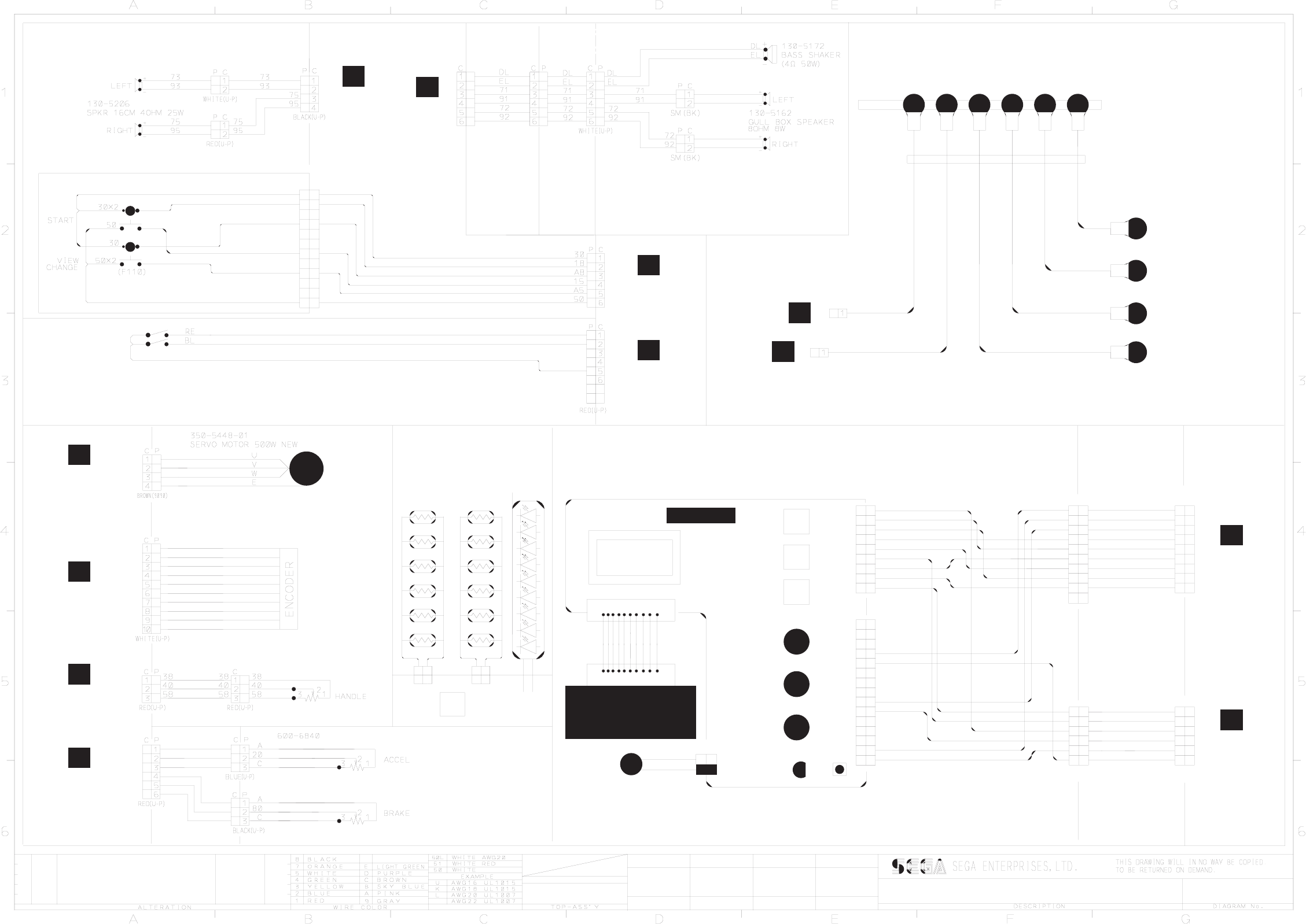
TEST
1 2 3 4 5 6 7 8 9 10
EP1003
COUNTER IMPULSE
VOL 3
AMP CST 100
SERVICE
VOL 2
VOL 1
N/U
9 WAY U-P BLACK15 WAY U-P BLACK
EARTH MAP
C
P
M4
M4
M4M4
M4
M4
TRANSFORMER
M5
M4
M4
M4
COIN CHUTE TOWER
HANDLE MECHA
BASE BOX
AC BRKT
ORP-2350UK
ASSY REAR CABI
LED BRAKE
LIGHT ARRAY
ORP-2363UK
12 X 12V 2.2W
WEDGE TYPE
BULB
1
2
U-P
C P
C P
U-P
2
1
10
50
ORP-2050UK
ASSY FRONT CABI
ORP-2260UK
FLOOR CENTRE
ASSY
SPG-2200
ASY BRAKE & ACCEL
ORP-2050UK ASSY FRONT CABI
ORP-3020UK
ASSY BASE BOX
ORP-60047UK
(ORP-6001UK)
MONEY CONTROLS
SR3 COIN MECH
ORP-60014UK
A5
A8
15
18
30
18
A8
15
A5
50
30
18
A8
15
A5
50
1
2
3
4
5
6
7
8
9
10
11
12
FRI-61063
WH
WH
RE
BL
8
7
PADDLE UP
PADDLE DWN
ORP-60011UK
ORP-60012UK
ORP-60029UKORP-60030UK
ORP-60030UK
ORP-60031UK
ORP-60032UK
OUTRUN 2 SPECIAL DLX
ORP-0000UK
TO (1/3)
POS: E3 A2
A1
POS: F2
TO (1/3)
V POS: C2
T0 (2/3)
U-P
10
D
POS: A5
TO (1/3)
ORP-2100 ASSY SW PLATE
DRAWN CHKD
09/12/04
CW SCHEM. 3/3
102
U-P
39
75
D5
50
50
10
2
LM1006 LAMP
L
CABLE
E162690
D5
2
1
STATUS
BASS SHAKERS
FRONT & REAR
31 1
52
8
58 9
48
38
6
7
3
42
32
5
4
51
41 2
SERVICE
15
12
13
14
11
10
75
41
FRONT (BGM)
SPEAKERS
PC
5
7
8
9
6
4
3
1
2
39
51
31
7
C
8
9
6
5
3
4
P
58
10
38
52
50
32
48
ORP-60042UK
VTS-HOD 1
42
50
2
6
5
3
4
P C
1
U-P BLUE
P C
SPEAKERS
REAR (SE)
U-P
TO (2/3)
POS: G5
91
92
95
50
E8
71
72
75
73
30
38
20
58
38
80
58
38
20
58
38
80
58
U-P
D5
39 6
75 4
5
50
50 2
3
10 1
P C
ORP-60013UK
ORP-60042UK
P
POS: A5
TO (1/3)
Q
POS: G4
TO (1/3)
K
POS: G5
TO (1/3)
L
POS: G6
TO (1/3)
M
POS: A4
TO (1/3)
N
TO (2/3)
POS: G3
H
J
TO (2/3)
POS: G4
TO (1/3)
POS: A4
C
ORP-3100UK ASSY COIN CHUTE TOWER
TEST/SERVICE/CREDIT/VOLUMES CONTROLLER
ORP-2050UK ASSY FRONT CABI
ORP-2400UK ASSY SEAT
1
2
4
5
3
7
6
9
8
P C
41
51
32
42
38
48
58
52
31 31
52
58
48
38
42
32
51
41
ORP-60027UK
ORP-60049UK
FRI-2600
PADDEL SHIFT
LED
SEAT BASE
FRI-2550
ASSY HANDLE MECHA
ORP-2050UK ASSY FRONT CABI
ORP-2050UK
FRONT CABI
ASSY
