Arcade R Tuned Manual 00 RNE COVER Rev User
2013-11-22
User Manual: Arcade R-Tuned Manual
Open the PDF directly: View PDF ![]() .
.
Page Count: 119 [warning: Documents this large are best viewed by clicking the View PDF Link!]

OWNER'S MANUAL
IMPORTANT
• Before using this product, read this manual carefully to understand the
contents herein stated.
• After reading this manual, be sure to keep it near the product or in a
convenient place for easy reference when necessary.
800 ARTHUR AVENUE, ELK GROVE VILLAGE, IL 60007-5215
Phone: 888-877-2669 Facsimile: 847-427-1065
WEB: WWW.SAU.SEGA.COM
© SEGA
All manufacturers, cars, names, brands and associated imagery featured in this game are trademarks and/or
copyrighted materials of their respective owners. All rights reserved.
553-30-300
1ST PRINTING JAN.2009
SEGA AMUSEMENTS U.S.A., INC.
TM

TABLE OF CONTENTS
i
TABLE OF CONTENTS
BEFORE USING THE PRODUCT, BE SURE TO READ THE FOLLOWING:
TABLE OF CONTENTS ....................................................................................... i
INTRODUCTION ................................................................................................ iii
1 1 HANDLING PRECAUTIONS ......................................................................... 1
2 2 PRECAUTIONS REGARDING INSTALLATION LOCATION ........................ 5
2-1 LIMITATIONS OF USAGE ................................................................................................5
2-2 OPERATION AREA ..........................................................................................................6
3 3 PRECAUTIONS REGARDING PRODUCT OPERATION ............................. 7
4 4 PART DESCRIPTIONS ................................................................................ 11
5 5 ACCESSORIES ........................................................................................... 12
6 6 ASSSEMBLY AND INSTALLATION ............................................................ 13
6-1 FIXATION TO INSTALLATION SITE ..............................................................................15
6-2 TURNING ON THE POWER (SOFTWARE INSTALLATION) ........................................17
6-3 CHECKING ASSEMBLY (SETUP) .................................................................................22
7 7 PRECAUTIONS WHEN MOVING THE MACHINE ...................................... 25
88 GAME DESCRIPTION ................................................................................. 27
8-1 GAME OVERVIEW .........................................................................................................27
8-2 MODE OVERVIEW .........................................................................................................30
8-3 HOW TO PLAY ...............................................................................................................31
8-4 HINTS FOR PLAYING THE GAME ................................................................................39
9 9 TEST MODE ................................................................................................ 40
9-1 SWITCH UNIT AND COIN METER ................................................................................41
9-2 SYSTEM TEST MODE ...................................................................................................42
9-3 GAME TEST MODE .......................................................................................................43
101CONTROL PANEL (HANDLE MECHA) ..................................................... 62
10-1 REMOVING THE CONTROL PANEL ...........................................................................63
10-2 ADJUSTING/REPLACING THE VOLUME ...................................................................64
10-3 GREASING ...................................................................................................................66

ii
TABLE OF CONTENTS
1 1 1 SHIFT LEVER............................................................................................. 67
11-1 REMOVING THE SHIFT LEVER ..................................................................................67
11-2 SWITCH REPLACEMENT ............................................................................................68
12 1ACCELERATOR & BRAKE ....................................................................... 69
12-1 VOLUME ADJUSTMENT AND REPLACEMENT ........................................................70
12-2 GREASING ...................................................................................................................72
13 3MONITOR ................................................................................................... 73
13-1 CAUTIONS AND WARNINGS CONCERNING
THE SAFETY FOR HANDLING THE MONITORS ......................................................73
13-2 CLEANING THE CRT SURFACES ..............................................................................76
13-3 ADJUSTMENT PROCEDURE ......................................................................................77
14 1FLUORESCENT LIGHT/OTHER LAMPS REPLACEMENT ..................... 79
151 PERIODIC INSPECTION ........................................................................... 83
161 TROUBLESHOOTING ............................................................................... 85
16-1 TROUBLESHOOTING (WHEN NO ERROR MESSAGE IS SHOWN) .........................85
16-2 ERROR MESSAGES ....................................................................................................89
171GAME BOARD............................................................................................ 91
17-1 REMOVING THE LINDBERGH ....................................................................................91
17-2 COMPOSITION OF THE GAME BOARD ....................................................................93
181COMMUNICATION PLAY ........................................................................... 94
18-1 INSTALLATION PRECAUTIONS .................................................................................94
18-2 CONNECTING THE COMMUNICATION CABLE ........................................................96
18-3 NETWORK PLAY SETTINGS ......................................................................................97
18-4 NETWORK PLAY PRECAUTIONS ..............................................................................98
191DESIGN-RELATED PARTS ........................................................................ 99
202PARTS LIST .............................................................................................. 100
212WIRE COLOR CODE TABLE ................................................................... 110
222WIRING DIAGRAM ................................................................................... 111
INTRODUCTION
iii
INTRODUCTION
This manual is intended to provide detailed descriptions together with all the necessary information covering the
general operation of electronic assemblies, electro-mechanicals, servicing control, spare parts, etc. for the product,
“SEGA R-TUNED SITDOWN.”
This manual is intended for the owners, personnel and managers in charge of operation of the product.
Operate the product after carefully reading and sufciently understanding the instructions.
In the unlikely event that the product does not function correctly, DO NOT allow anyone other than a technician
to touch the internal system. Turn off the power to the machine, making sure to unplug the electrical cord from the
outlet, and contact the ofce listed below or the point of purchase for this product.
Use of this product is unlikely to cause physical injuries or damage to property. However, points that require special
attention are indicated by bold text, the word “IMPORTANT” and the symbol below.
Indicates important information that, if ignored, may result in the mishandling of
the product and cause faulty operation or damage to the product.
Sega Amusements U.S.A., Inc.
800 Arthur Avenue, Elk Grove Village, IL 60007-5215, U.S.A.
TEL: 1-847-364-9787
TOLL FREE: 1-888-877-2669
FAX: 1-847-427-1065
SPECIFICATIONS
Dimensions: Unit : 36.5” [Width] x 69.1” [Depth] x 74.5” [Height]
Weight: Unit : 562.2 lbs.
Power, maximum current: 540 W, 4.5 A (AC 120 V, 60 Hz)
Monitor: 29 Type Color Monitor
NOTE: The contents herein described are subject to change without notice.
iv
INTRODUCTION
Denition of 'Site Maintenance Personnel or Other Qualied Individuals'
Procedures not described in this manual or marked as 'to be carried out by site
maintenance personnel or other qualied professionals' should not be carried
out by personnel without the necessary skill or technology. Work carried out by
unqualied persons may cause serious accidents, including electrocution.
Parts replacement, maintenance inspections and troubleshooting should be carried out by site maintenance personnel
or other qualied professionals. This manual includes directions for potentially dangerous procedures which should
only be carried out by professionals with the appropriate specialized knowledge.
The site maintenance personnel or other qualied professionals mentioned in this manual are dened as follows:
Site maintenance personnel:
Individuals with experience in maintaining amusement equipment, vending machines, etc., working under the
supervision of the owner/operator of this product to maintain machines within amusement facilities or similar
premises by carrying out everyday procedures such as assembly, maintenance inspections, and replacement of units/
expendable parts.
Activities to be carried out by site maintenance personnel:
Amusement equipment/vending machine assembly, maintenance inspection and replacement of units/expendable
parts.
Other qualied professionals:
Persons employed by amusement equipment manufacturers, or involved in design, production, testing or
maintenance of amusement equipment. The individual should have either graduated from technical school or hold
similar qualications in electrical/electronics/mechanical engineering.
Activities to be carried out by other qualied professionals:
Amusement equipment/vending machine assembly, repair/adjustment of electrical/electronic/mechanical parts.
HANDLING PRECAUTIONS
1
1
HANDLING PRECAUTIONS
1
• Beforeperformingwork,besuretoturnthepoweroff.Performingthework
withoutturningthepoweroffcancauseanelectricshockorshortcircuit.Inthe
caseworkshouldbeperformedinthestatusofpoweron,thismanualalways
statestothateffect.
• Toavoidanelectricshockorshortcircuit,donotpluginorunplugquickly.
• Toavoidanelectricshock,donotpluginorunplugwithawethand.
• Donotexposepowercordsorearthwiresonthesurface,(oor,passage,
etc.).Ifexposed,thepowercordsandearthwiresaresusceptibletodamage.
Damagedcordsandwirescancauseanelectricshockorshortcircuit.
• Toavoidcausingareoranelectricshock,donotputthingsonordamagethe
powercords.
• Whenorafterinstallingtheproduct,donotunnecessarilypullthepowercord.If
damaged,thepowercordcancauseareoranelectricshock.
• Incasethepowercordisdamaged,askforareplacementthroughwherethe
productwaspurchasedfromortheofcehereinstated.Usingthecordasis
damagedcancausere,anelectricshockorleakage.
• Besuretoperformgroundingappropriately.Inappropriategroundingcan
causeanelectricshock.
• Besuretousefusesmeetingthespeciedrating.Usingfusesotherthanthe
speciedratingcancauseareoranelectricshock.
• BesurethatconnectionssuchasICBDaremadeproperly.Insufcientinsertion
cancauseanelectricshock.
• Specicationchanges,removalofequipment,conversionand/oraddition,not
designatedbySEGAarenotpermitted.
-Failuretoobservethismaycauseareoranelectricshock.Non-compliance
withthisinstructioncanhaveabadinuenceuponphysicalconditionsofthe
playersortheonlookers,orresultininjuryduringplay.
-SEGAshallnotbeheldresponsiblefordamage,compensationfordamagetoa
thirdparty,causedbyspecicationchangesnotdesignatedbySEGA.
• Donotperformanyworkorchangepartsnotlistedinthismanual.Doingsomay
leadtoanaccident.
Ifyouneedtoperformanyworknotlistedinthismanual,requestworkfromthe
ofceindicatedinthismanualorthepointofpurchase,orinquiresfordetails.
• Besuretoperformperiodicmaintenanceinspectionshereinstated.
When installing or inspecting the machine, be very careful of the following points and pay attention to ensure that
the player can enjoy the game safely.
Non-compliance with the following points or inappropriate handling running counter to the cautionary matters
herein stated can cause personal injury or damage to the machine.
1
HANDLING PRECAUTIONS
2
• FortheICboardcircuitinspections,onlythelogictesterisallowed.Theuseofa
multiple-purposetesterisnotpermitted,sobecarefulinthisregard.
• WhencleaningtheCRTsurfaces,useasoftanddrycloth.Donotapply
chemicalssuchasthinner,benzene,etc.
• Staticelectricityfromyourbodymaydamagesomeelectronicsdevicesonthe
ICboard.BeforehandlingtheICboard,touchagroundedmetallicsurfaceso
thatthestaticelectricitycanbedischarged.
• Somepartsarenotdesignedandmanufacturedspecicallyforthisgame
machine.Themanufacturersmaydiscontinue,orchangethespecicationsof
suchgeneral-purposeparts.Ifthisisthecase,SEGAcannotrepairorreplacea
failedgamemachinewhetherornotawarrantyperiodhasexpired.

HANDLING PRECAUTIONS
1
3
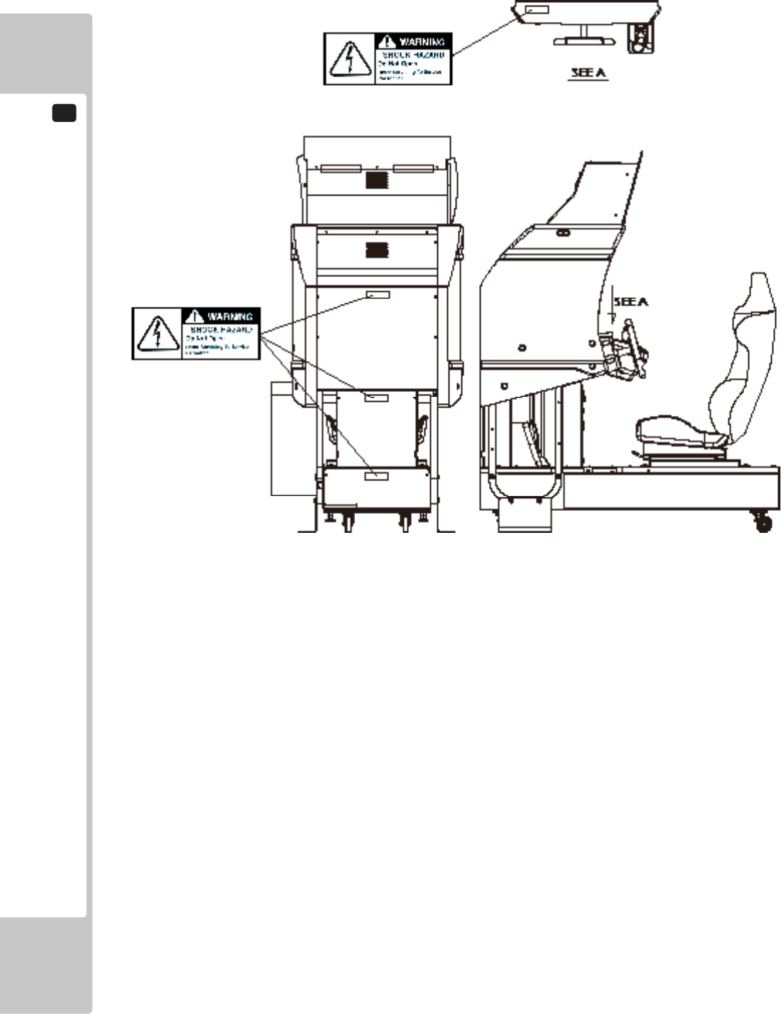
CONCERNINGTHESTICKERDISPLAY CONCERNINGWARNINGDISPLAYS
This SEGA product has stickers attached describing
the product manufacture No. (Serial No.) and Electrical
Specications. It also has a Sticker describing where to
contact for repair and for purchasing parts.
When inquiring about or asking for repairs, mention
the Serial No. and Name of Machine indicated on
the Sticker. The Serial Number indicates the product
register. Identical machines could have different
parts depending on the date of production. Also,
improvements and modications might have been made
after the publication of this manual. In order to ensure
you order the correct parts, mention the Serial No. when
contacting the applicable places.
This SEGA product has warning displays on stickers,
labels and/or printed instructions adhered/attached to or
incorporated in the places where a potentially hazardous
situation could arise. The warning displays are intended
for accident prevention for customers and for avoiding
hazardous situations relating to maintenance and
servicing work. Some portions of the cabinet contain
high voltage and may cause accidents if touched. When
performing maintenance, be very careful of the warning
displays. It is especially important that any complex
repair and replacement work not mentioned herein
should be performed by those technical personnel who
have knowledge of electricity and technical expertise.
In order to prevent accidents, caution any customer
ignoring the warnings to cease and desist immediately.
1
HANDLING PRECAUTIONS
4
PRECAUTIONS REGARDING INSTALLATION LOCATION
2
5
PRECAUTIONS REGARDING INSTALLATION LOCATION
2
2-1 LIMITATIONS OF USAGE
Thisproductisanindoorgamemachine.Donotinstallitoutside.Evenindoors,
avoidinstallinginplacesmentionedbelowsoasnottocauseare,electric
shock,injuryand/ormalfunction.
-Placessubjecttorainorwaterleakage,orplacessubjecttohighhumidityin
theproximityofanindoorswimmingpooland/orshower,etc.
-Placessubjecttodirectsunlight,orplacessubjecttohightemperaturesinthe
proximityofheatingunits,etc.
-Placeslledwithinammablegasorvicinityofhighlyinammable/volatile
chemicalsorhazardousmatter.
-Dustyplaces.
-Slopedsurfaces.
-Placessubjecttoanytypeofviolentimpact.
-Vicinityofanti-disasterfacilitiessuchasreexitsandreextinguishers.
-Areaswherethetemperatureexceedstheapplicabletemperature(ambient
temperature)rangeof5to30degreescentigrade.
• BesuretochecktheElectricalSpecications.Ensurethatthisproduct
iscompatiblewiththelocation'spowersupply,voltage,andfrequency
requirements.AplatedescribingElectricalSpecicationsisattachedtothe
product.Non-compliancewiththeElectricalSpecicationscancauseare
andelectricshock.
• Thisproductrequiresabreakerandearthmechanismaspartofthelocation
facilities.Usingtheproductwithoutthesecancauseareandelectricshock.
• Ensurethattheindoorwiringforthepowersupplyisratedat15Aorhigher
(ACsinglephase100V~120Varea).Non-compliancewiththeElectrical
Specicationscancauseareandelectricshock.
• Besuretouseanindependentpowersupplyequippedwithanearthleakage
breaker.Usingapowersupplywithoutanearthleakagebreakercancausean
outbreakofreifapowersurgeoccurs.
• Puttingmanyloadsononeelectricaloutletcancausegenerationofheatanda
reresultingfromoverload.
• Whenusinganextensioncord,ensurethatthecordisratedat15Aorhigher
(AC100V~120Varea).Usingacordratedlowerthanthespeciedratingcan
causeareandelectricshock.
2
PRECAUTIONS REGARDING INSTALLATION LOCATION
6
Toinstallthisproduct,theentrancemustbeatleast1minwidthand1.8minheight.
2-2 OPERATION AREA
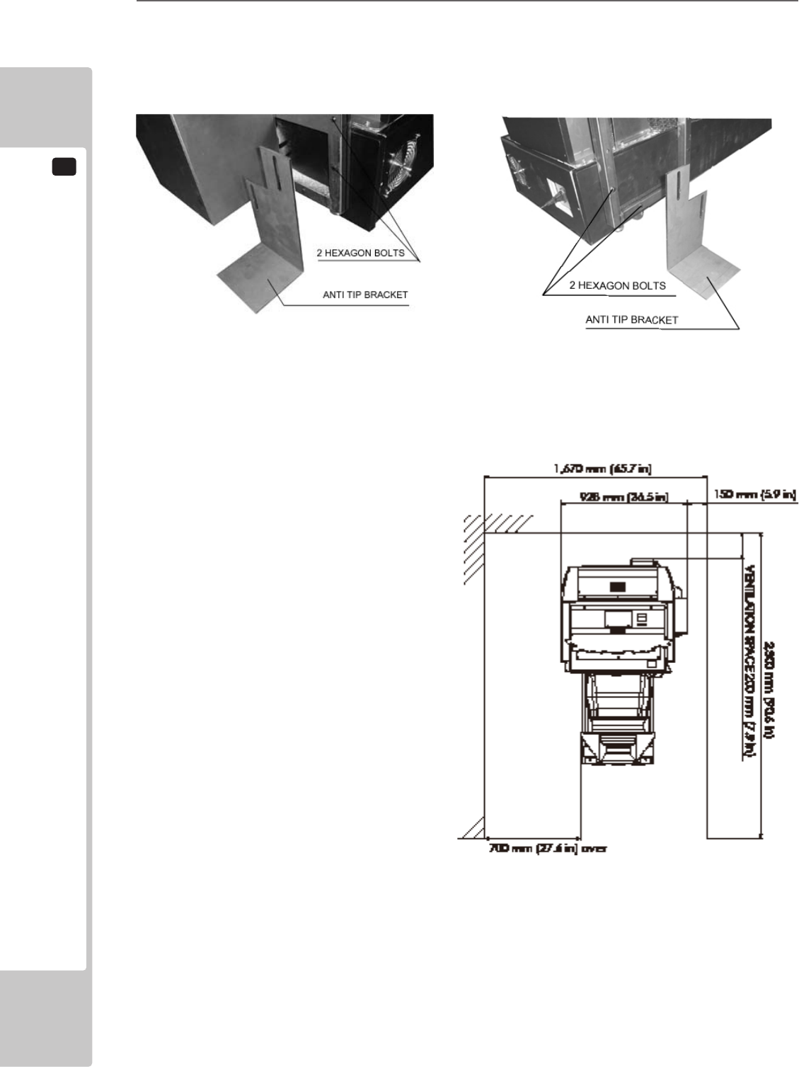
• Forsafeoperation,useandoperatethisproductinanareameasuringatleast
1.67m(65.7in)inwidthand2.3m(90.6in)indepth.Theareaprescribedinthis
manualisabsolutelynecessary,forifoneshouldfalloverandhittheirhead
againstsomething,therecouldbeaseriousaccident.
• Besuretoprovidesufcientspacespeciedinthismanual.Donotallowobjects
toblocktheventilationports.Itcancausegenerationofheatandare.
• SEGAshallnotbeheldresponsiblefordamageorcompensationfordamageto
athirdparty,resultingfromthefailuretoobservethisinstruction.
• Ifthemachinedoesnottthroughtheentrywaytotheinstallationlocation,do
notdisassembleitwithoutrstconsultingtheinstructions.Themachineshould
onlybedisassembledinaccordancewiththeinstructionslistedinthismanual;
donotattempttodisassembleitinanyotherway.Thismaycauseelectric
shockorshortcircuits.
PRECAUTIONS REGARDING PRODUCT OPERATION
3
7
To avoid injury and trouble, be sure to pay attention to the behavior of visitors and players.
BEFORE OPERATION
PRECAUTIONS REGARDING PRODUCT OPERATION
3
Inordertoavoidaccidents,checkthefollowingbeforestartingtheoperation:
• Toensuremaximumsafetyfortheplayersandthecustomers,ensurethatwhere
theproductisoperatedhassufcientlightingtoallowanywarningstoberead.
Operationunderinsufcientlightingcancausebodilycontactwitheachother,
hittingaccident,and/ortroublebetweencustomers.
• Besuretoperformappropriateadjustmentofthemonitor(projector).For
operationofthismachine,donotleavemonitor'sickeringordeviationas
is.Failuretoobservethiscanhaveabadinuenceupontheplayers'orthe
customers'physicalconditions.
• Itissuggestedtoensureaspaceallowingtheplayerswhofeelsickwhile
playingthegametotakearest.
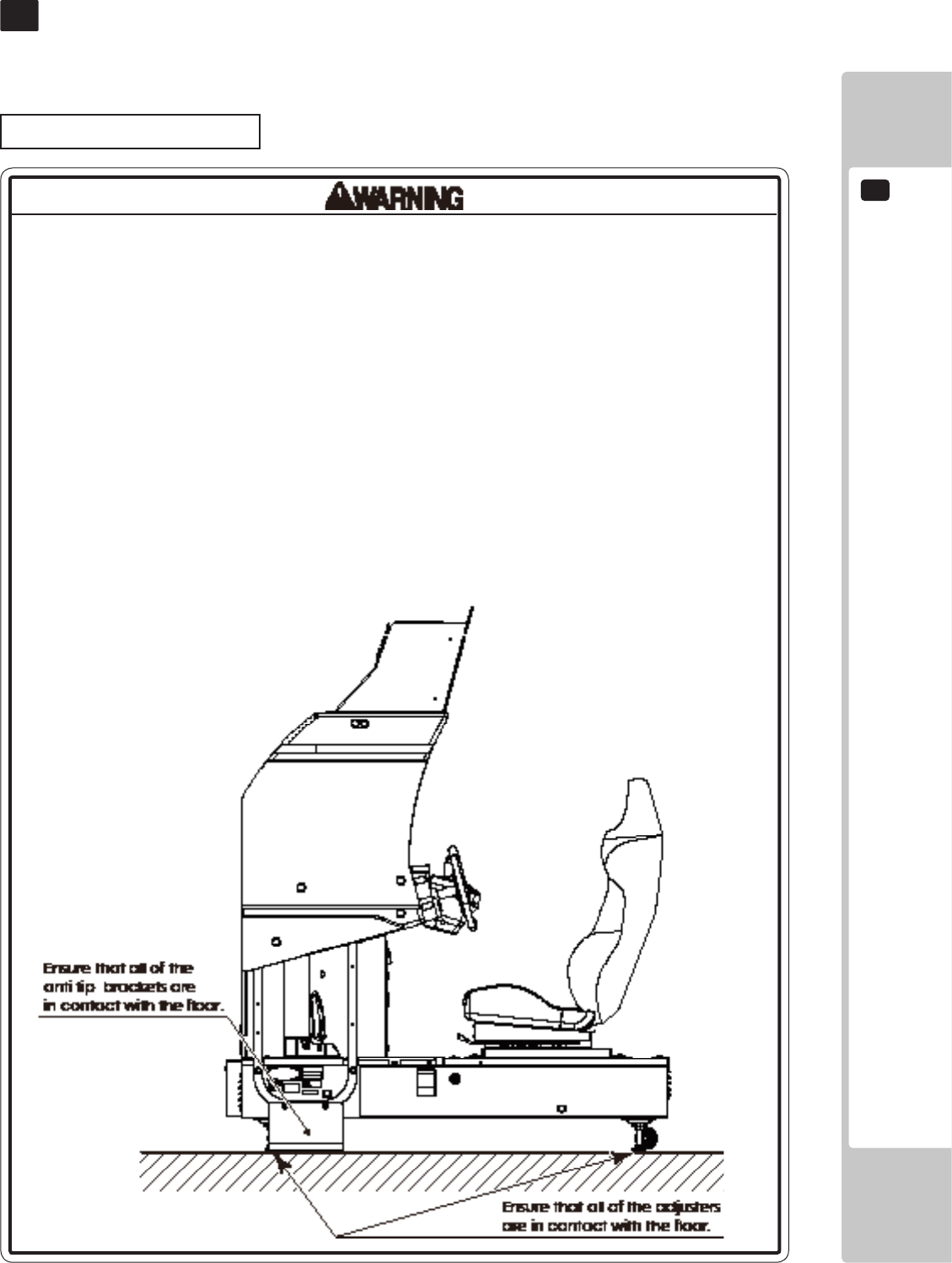
• Checkifalloftheadjustersareincontactwiththesurface.Iftheyarenot,the
Cabinetcanmoveandcauseanaccident.
3 FIG. 01
3
PRECAUTIONS REGARDING PRODUCT OPERATION
8
• Duringdailycleaning,besuretocheckthesurfaceofthesteeringwheel,gear
shifter,andotherpartsthattheplayertoucheswithhishandsfordamage,
cracks,orloosescrews.Ifaplayerusesthemachinewhileitisdamaged,
cracked,orhasaloosescrew,theplayermaybecomeinjured.
• Duringdailycleaning,besuretochecktheseatforanyabnormality,wetness,
etc.Failuretodothismayresultindeliberatetamperingornegligencebeing
leftundetected.
• Toavoidinjury,besuretoprovidesufcientspacebyconsideringthepotentially
crowdedsituationattheinstallationlocation.Insufcientinstallationspacecan
causemakingbodilycontactwitheachother,hittingaccidents,and/ortrouble
betweencustomers.
• Donotputanyheavyitemonthisproduct.Placinganyheavyitemonthe
productcancauseafallingdownaccidentorpartsdamage.
• Donotclimbontheproduct.Climbingontheproductcancausefallingdown
accidents.Tocheckthetopportionoftheproduct,useastepladder.
• Toavoidelectricshock,checktoseeifdoor&coverpartsaredamagedor
omitted.
• Toavoidelectricshock,shortcircuitand/orpartsdamage,donotputthe
followingitemsonorintheperipheryoftheproduct.Flowervases,owerpots,
cups,watertanks,cosmetics,andreceptacles/containers/vesselscontaining
chemicalsandwater.
PRECAUTIONS REGARDING PRODUCT OPERATION
3
9
DURING OPERATION (PAYING ATTENTION TO CUSTOMERS)
• Forsafetyreasons,donotallowanyofthefollowingpeopletoplaythegame.
-Thosewhoneedassistancesuchastheuseofanapparatuswhenwalking.
-Thosewhohavehighbloodpressureoraheartproblem.
-Thosewhohaveexperiencedmuscleconvulsionorlossofconsciousnesswhen
playingvideogames,etc.
-Thosewhohaveneckorspinalcordproblems.
-Thosewhoareintoxicatedorundertheinuenceofdrugs.
-Pregnantwomen.
-Personssusceptibletomotionsickness.
-Personswhodisregardtheproduct'swarningdisplays.
• Evenplayerswhohaveneverbeenadverselyaffectedbylightstimulusmight
experiencedizzinessorheadachedependingontheirphysicalconditionwhen
playingthegame.Smallchildrenareespeciallylikelytoexperiencethese
symptoms.Cautionguardiansofsmallchildrentokeepwatchontheirchildren
duringplay.
• Instructthosewhofeelsickduringplaytohaveamedicalexamination.
• Toavoidinjuryfromfallsandelectricshocksduetospilleddrinks,instructthe
playernottoplaceheavyitemsordrinksontheproduct.
• Toavoidelectricshocksandshortcircuits,donotallowcustomerstoput
handsandngersorextraneousmatterintheopeningsoftheproductorsmall
openingsinoraroundthedoors.
• Toavoidfallsandresultinginjury,immediatelystopthecustomerfromleaning
againstorclimbingontheproduct,etc.
• Toavoidelectricshockandshortcircuit,donotallowcustomerstounplugthe
powerplugwithoutajustiablereason.
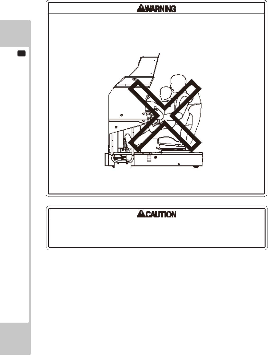
• Thisgameisforoneplayeronly.Iftwoormorecustomersattempttositinthe
seatandplayatthesametime,itmayresultsinplayersfallingover,fallingoff,
orcatchingbodypartsintheride.
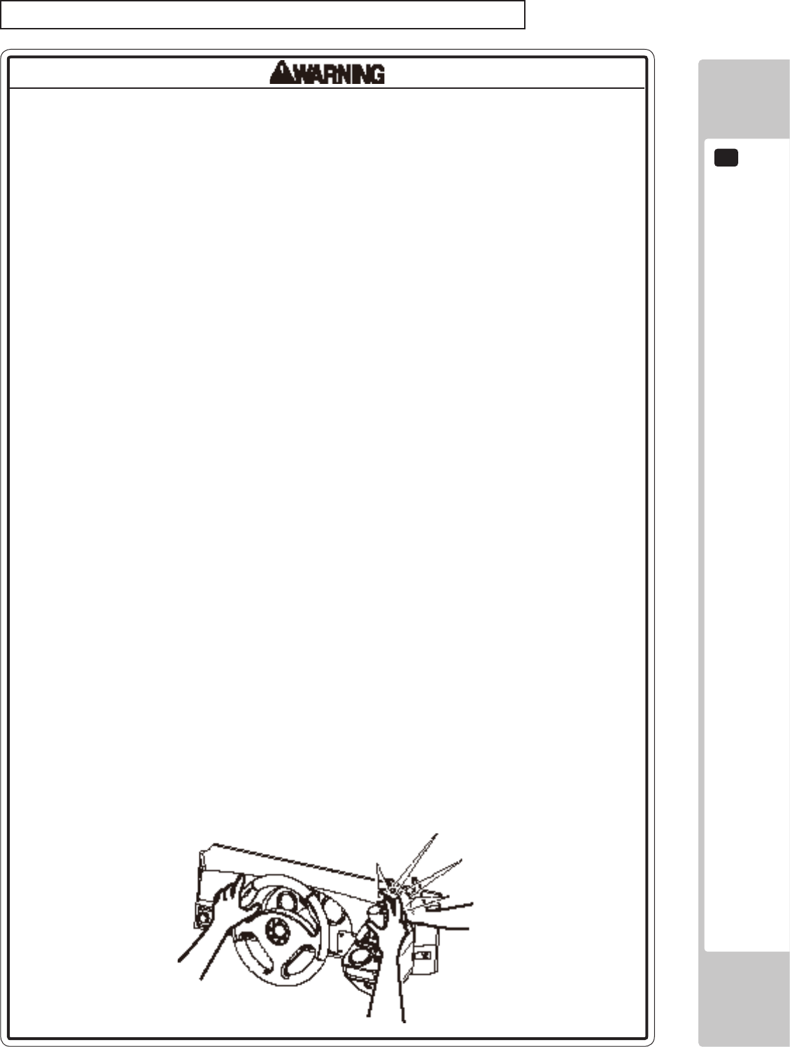
• Personsotherthantheplayershouldnotbeallowedtotouchthecontrolsduring
play.Theymaybrushagainstorcollidewiththecontrolsortheplayer,possibly
resultinginaccidents.
3 FIG. 02
3
PRECAUTIONS REGARDING PRODUCT OPERATION
10
Immediatelystopsuchviolentactsashittingandkickingtheproduct.Suchviolent
actscancausepartsdamageorfallingdown,resultingininjuryduetofragments
andfallingdown.
• Customersshouldbewarnednottoplacechildrenontheirlapswhiletheyplay
thegame.Doingsomaycausethechildtobecometrappedbetweenthe
playerandthecontrolpaneland/orcausethemachinetotipover.
3 FIG. 03
PARTS DESCRIPTIONS
4
11
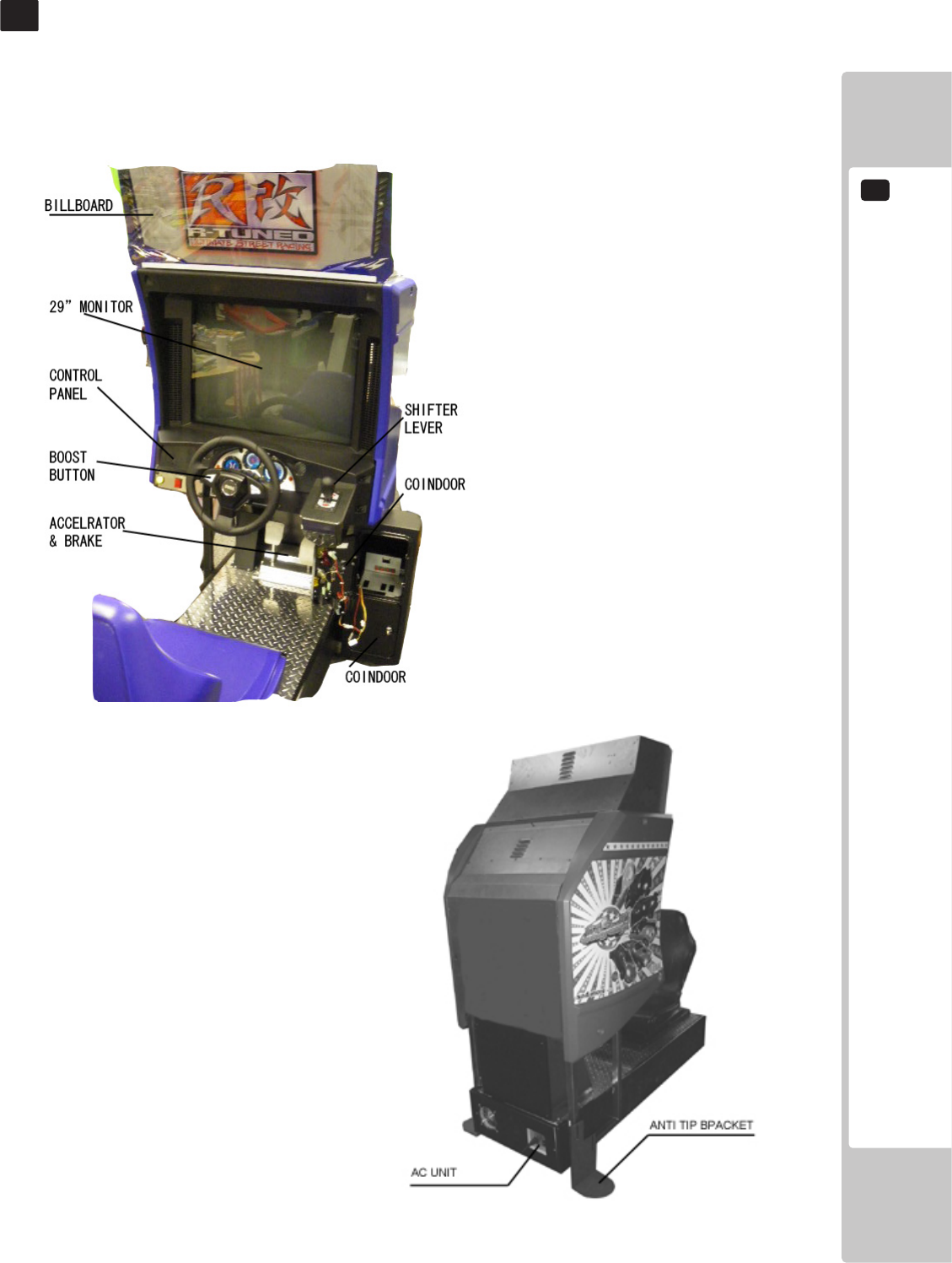
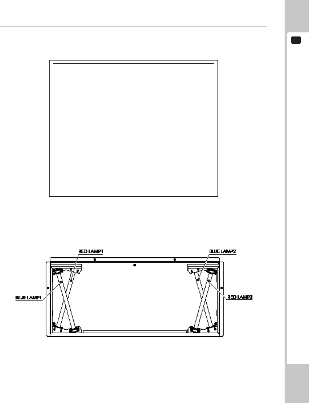
4 FIG. 02 Rear View
PART DESCRIPTIONS
4
5
ACCESSORIES
12
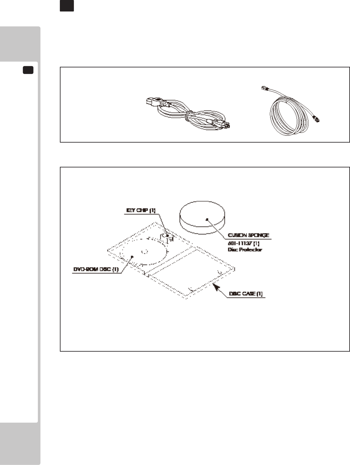
Conrm that the accessories listed in the table below are present when setting up the product. Accessories marked
“Spare” in the note column are consumable items but included as spares.
5 TABLE 01
5 TABLE 02 SOFTWARE KIT 610-0727-0060<USA>
ACCESSORIES
5
OWNER’S MANUAL
553-30-300 (1)
This manual
AC CABLE (Power Code) COMMUNICATION CABLE 5m
99-00-017 (1)
DVD SOFTWARE KIT (1)
When you order the DVD-ROM disc only, specify the part number 610-0726-0044 (DVD SOFT RTV).
NOTE; The game software has been pre-installed in the main PCB and the
key chip has been pre-set to the main PCB.
Please use the DVD software, only when necessary for some reason
such as replacing the main PCB.
However to install the software, the DVD DRIVE and USB(mini type)
cabele need to be prepared separately.
Those are not included in the unit and available separately at SEGA.
ASSEMBLY AND INSTALLATION
6
13
ASSEMBLY AND INSTALLATION
6
• Performassemblyworkbyfollowingtheprocedurehereinstated.Failureto
complywiththeinstructionscancauseelectricshock.
• Performassemblingasperthismanual.Sincethisisacomplexmachine,
incorrectassemblingcancauseanelectricshock,machinedamageand/or
improperfunctioningasperspeciedperformance.
• Whenassembling,morethanonepersonisrequired.Dependingonthe
assemblywork,therearesomecasesinwhichworkingbyonepersonalone
cancausepersonalinjuryorpartsdamage.
• Ensurethatconnectorsareproperlyconnected.Improperconnectionscan
causeelectricshock.
• Thisworkshouldbecarriedoutbythesitemaintenancepersonnelorother
qualiedprofessionals.Workperformedbynon-technicalpersonnelcancause
asevereaccidentsuchaselectricshock.Failingtocomplywiththisinstruction
cancauseasevereaccidentsuchaselectricshocktotheplayerduring
operation.Ifnoonewithpropertechnologicalexpertiseisavailable,request
servicefromtheofceindicatedinthisdocumentorthepointofpurchasesoas
toensuresafety.
• Providesufcientspacesothatassemblingcanbeperformed.Performing
workinplaceswithnarrowspaceorlowceilingmaycauseanaccidentand
assemblyworktobedifcult.
• Toperformworksafelyandavoidseriousaccidentsuchasthecabinetfalling
down,donotperformworkinplaceswherestep-likegradedifferences,aditch,
orslopeexist.
• Becarefulnottodamagethewires.Damagedwiresmaycauseelectricshock
orshortcircuitorpresentariskofre.
• Donotleavepowercords,groundwires,ornetworkcablesexposedinareas
ofheavyfoottrafc.Doingsomaycausethemtobecomedamaged,possibly
resultinginelectricshockand/orshortcircuits.Whenlayingwiringacrossthe
oor,alwaysusesafetycoverstoprotectthewires.
• Thepowercordforthisproducthasagroundterminal.Makesuretousethis
groundterminalwhenpluggingitintoanindooroutlet.Failuretoproperly
groundtheproductcouldleadtoelectrocution.Itcanalsoleadtomalfunction.
6
ASSEMBLY AND INSTALLATION
14
When carrying out the assembling and installation, follow the following 6-item sequence.
6-1 Fixation to installation site
6-2 Turning on the power (Software Installation)
6-3 Checking assembly (Setup)
• Whenopening/closing,attaching/removingdoorsorlids,becarefulthatyour
handorngerdoesnotgetcaughtinanything.
• Toperformtheoperationsafelyandaccuratelyyoumustuseasafe,steady
footstoolorstepladder.Workingwithoutthismayleadtoafallandpossible
injury.
• Wearappropriateworkclothingsothatworkcanbeperformedsafely.Use
glovesandsafetyshoestopreventaccidentsorinjuries.
• Wheninstallingawireprotectioncoveroveraoor,useamaterialshaped
sothatnoonepassingbywillstumbleoverit.Usingamaterialthatcouldbe
stumbledovermightleadtoanaccidentalfall.
• Handleplasticpartswithcare.Excessiveweightorpressuremaycausethemto
breakandthebrokenpiecesmaycauseinjury.
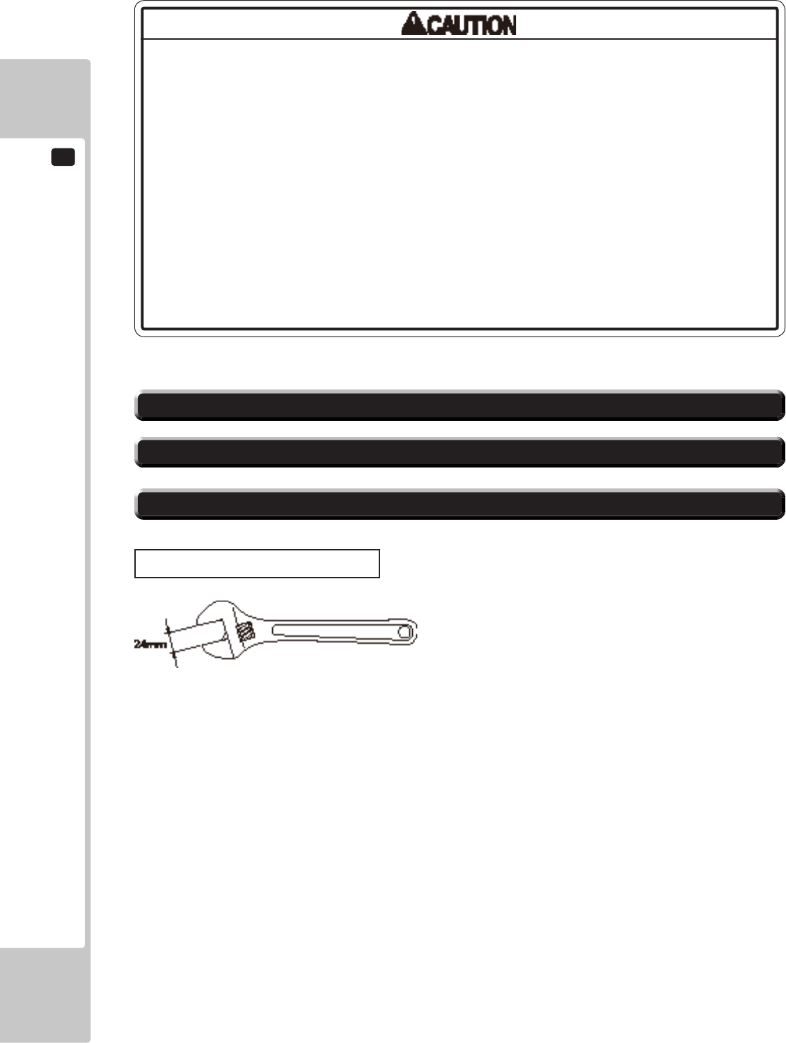
Tools necessary for work
Spanner with measuring distance of 24 mm to opposite side (for M16 hexagon bolts)
ASSEMBLY AND INSTALLATION
6
15
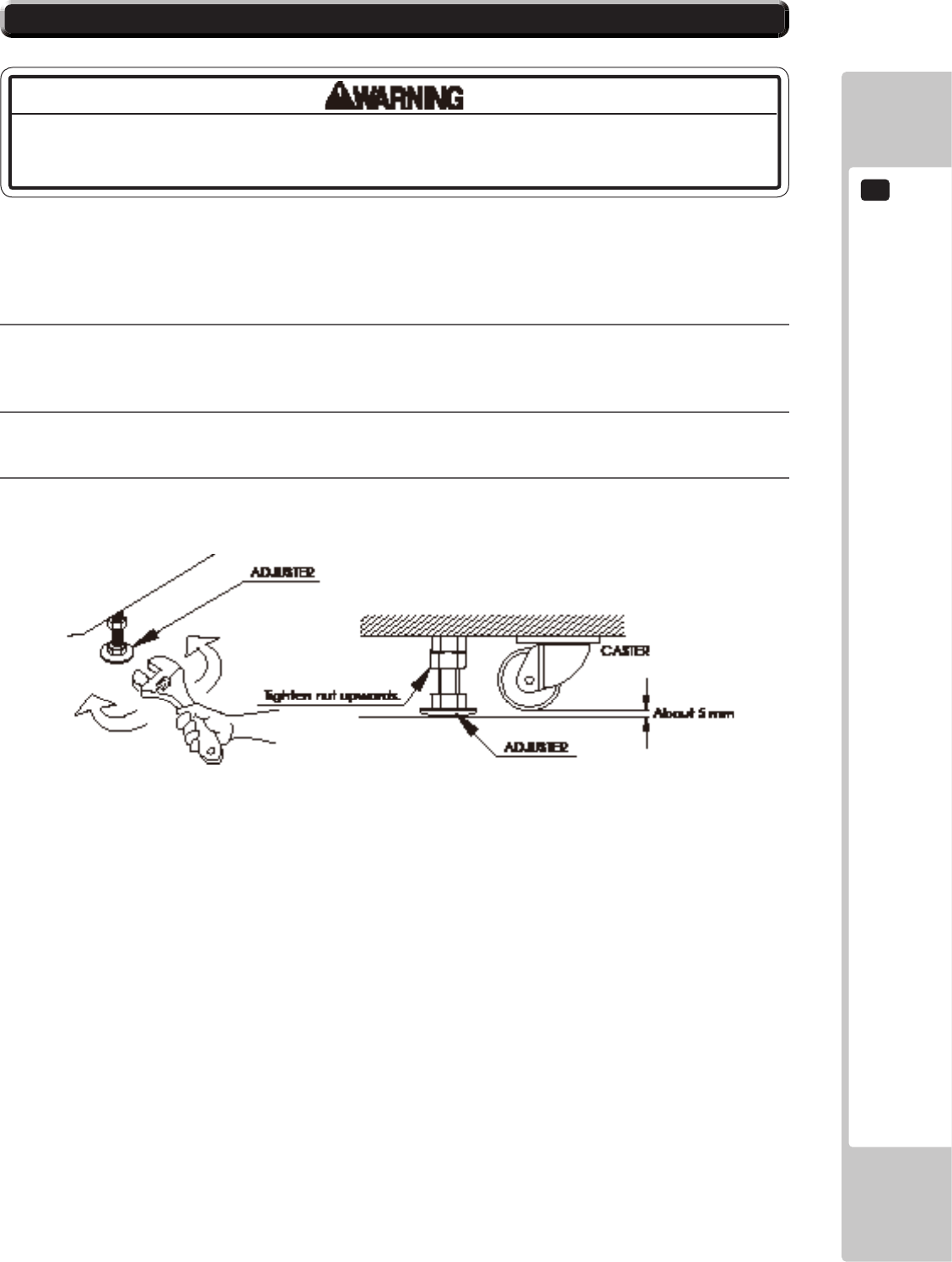
6-1 FIXATION TO INSTALLATION SITE
Makesurethatalltheadjusterscontacttheoor.Otherwisethecabinetcould
move,causinganaccident.
This product has 4 casters and 4 adjusters.
Up to 4 machines can be connected for multi-player games. If several machines are to be installed, refer to Chapter
19.
1
Move the product to the installation site. See Chapter 19 for an example of installation. Make sure to leave
enough passage space for the player to get into the seat. Also leave some space on the back lid side for
performing maintenance work later.
2
Have all the adjusters make contact with the oor. Adjust the adjuster’s height by using a wrench so that the
machine position is kept level.
3
After making adjustment, fasten the adjuster nut upward and secure the height of adjuster.
6-2 FIG. 02
6
ASSEMBLY AND INSTALLATION
16
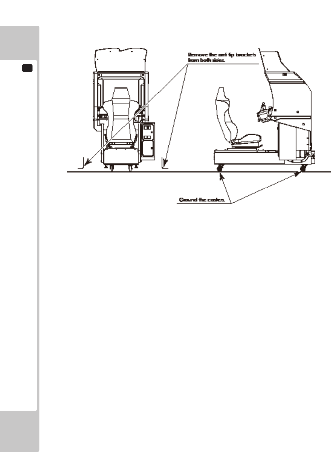
4
Attach the anti tip brackets to the left and right sides. Remove the 2 hexagon bolts from each side. These
will be used to fasten the anti tip brackets.
6-2 FIG. 03
Provide ventilation space for the ventilation opening.
Allow more than 70 cm (approx. 28 in) of space for
customer trafc.
6-2 FIG. 05
ASSEMBLY AND INSTALLATION
6
17
• DonotuseorstoretheDVDDRIVEorDVDwireinanyofthefollowinglocations,
asthismayresultinseriousdamage.
[Donotuseorstoreintheselocations]
-Anywherewhichmayvibrateorshocktheequipment
-Indirectsunlight
-Indampordustyplaces
-Inplaceswithasharpchangeintemperature
-Closetoanythingthatgivesoffheat(aheater,etc.)
-Closetoanythingwithastrongmagneticeld(magnets,monitor,speakers,
radio,etc.)
-Anywherethatislikelytogetwet(kitchen,etc.)
-Anywherewithaslopeorincline
-Anywherewithcorrosivegasintheair(chlorine,hydrogensulde,ammonia,
sulfurdioxide,etc.)
-Anywherewithstrongstaticelectricity
[Donotuseintheselocations]
-Closetoanythingthatishighlyretentiveofheat(carpet,sponge,cardboard,
etc.)
-AnywherethatblockstheDVDDRIVEairvent.
• TheDVDDRIVEisadelicatepieceofequipment.Avoidthefollowing.
-Droppingorshakingitviolently.
-Gettingwaterorotherliquidsonit,orplacingsmallitemsontopofit.
-Placinglargeorheavyitemsontopofit.
-DrinkingorsmokingclosetotheDVDDRIVE.
• DonotturnoffthepowertotheDVDDRIVEwhenitsaccesslampisonor
ashing,asthiscouldcausedamagetothedevice.
6-2 TURNING ON THE POWER (SOFTWARE INSTALLATION)
• BecarefulnottodamagetheDVDwirebygettingitcaughtbetweenobjects,
etc.Doingsomaycauseashortcircuitorre.
• Thefollowingexplanationassumesthattheproducthasbeenassembled
properlyasexplainedabove.Ifthereisanerrororiftheproductoperatesina
mannerotherthanasindicatedbelow,cutoffthepowersupplyimmediately.
Failuretodosomayresultinareorelectricalshock.
• IfyoulookdirectlyatthelaserbeamintheDVDDRIVE,youcouldsuffervision
impairment.DonotlookinsidetheDVDDRIVE.
The software installation is not necessary for this game, as it is pre-installed into the
main PCB. Please refer to the following section, only when necessary.
6
ASSEMBLY AND INSTALLATION
18
• Donotallowanyforeignmaterials,suchasliquids,metalsorsmokeinsidethe
DVDDRIVE.
• Useasoft,dryclothtowipeoffanydirtormarksontheDVDDRIVE.
-Ifyouneedtouseacleaningagent,alwaysusea“neutral”agentdilutedin
water.
-Neveruseproductsorcleaningagentscontainingbenzene,alcohol,thinners,
etc.
• DonottouchthelensinsidetheDVDDRIVE.Doingsomaypreventitfrom
readingaccurately.
• ThechipcomponentsonICboardscanbedamagedbyelectrostaticdischarge
fromthehumanbody.BeforehandlinganICboard,alwaysneutralizeanystatic
chargeinthebodybytouchingagroundedmetalsurface.
• Somepartsarenotdesignedandmanufacturedspecicallyforthekit.The
manufacturersmaydiscontinue,orchangethespecicationsofsuchgeneral
purposeparts.Ifthisisthecase,SEGAcannotrepairorreplaceafailedkit
whetherornotawarrantyperiodhasexpired.
ASSEMBLY AND INSTALLATION
6
19
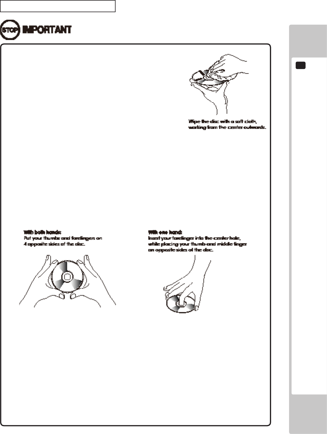
Handling the DVD-ROM Disc
• DonotuseaDVD-ROMwithadamagedfront.This
maycauseamalfunction.
• InserttheDVD-ROMintotheDVDDRIVEwiththe
labelfacingupwards.
• Donotgetngerprintsordustparticlesonthedisc.
Contaminateddiscsmayloweraudioandvideo
quality,andmayresultinreadmalfunctions.
• Whencleaningthedisc,donotusevolatile
chemicals(benzene,thinner,etc.),cleaning
sprays,orantistaticagents.
• Donotuseacracked,warped,ordamageddisc.Donotattachpapersorseals
ontothedisctoavoidscratchingit.Donotuseadiscwithsignsofpeeledseals,
tape,etc.IfsuchadiscisplacedintheDVD-ROMDRIVE,malfunctions,suchas
theinabilitytoremovethediscfromthedrive,mayresult.
• Whencleaningaheavilycontaminateddisc,useacleancloththathasbeen
soakedinwaterandsqueezed.Afterwiping,removeanyremainingmoisture
withaclean,drycloth.
• HowtoHoldaDisc
Whenhandlingadisc,becarefulnottocontaminateitwithyourngerprints.
• Thesoftwareisnotinstalledonthegameboard(LINDBERGH)whenthepower
supplyisengaged,sothe“Error22”messageisnotamalfunction.However,
ifthereisanothererrordisplay,orifthereisnovideooutputatall,theremight
havebeenanerrorinproductassembly,wiringconnectionsmightbefaulty,or
theLINDBERGHmightnotbefunctioningproperly.
• Afterthepowersupplyisengaged,waitfor“Error22”messagetobedisplayed.
Iftheproductisindiscriminatelyoperatedinanywaybeforehand,therecould
beunexpectedproblemsormalfunctions,aswellasdamagetoparts.
• Once“Error22”isdisplayed,settheDVD-ROMintheDVDDRIVEandre-engage
thepowersupply.Installationtakesplace.
6-5 FIG. 01
6-5 FIG. 02
6-5 FIG. 03
6
ASSEMBLY AND INSTALLATION
20
Take out the DVD software kit provided.
1
Turn on the MAIN POWER switch on the AC unit.
2
The LINDBERGH startup image appears on the screen. However, it does take several minutes for the
projector image to become visible. Wait for at least one minute. An error will occur. Check to see if it is
“Error 22.” If it is “Error 22,” proceed to the next operation. If it is not “Error 22,” take corrective measures
as indicated in the LINDBERGH service manual.
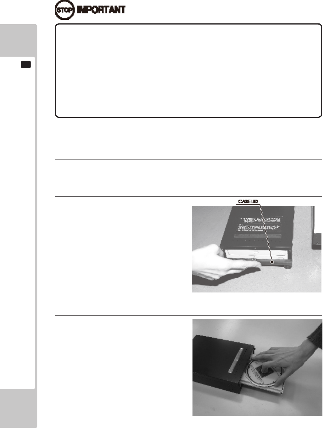
3
Remove 1 urea (resin-head) screw, and then
remove DVD DRIVE case lid.
4
Press the DVD DRIVE switch. The DVD DRIVE
tray comes out. Set the DVD from the DVD
software kit into the tray. Always have the DVD
label side facing upward.
6-5 FIG. 05
6-5 FIG. 04
• Afterthepowersupplyisengaged,theDVDDRIVEtraywillnotcomeout
forabout30secondsevenifyoupresstheswitch.ThisisduetoDVDDRIVE
initialization.
• TheDVDDRIVEtraycancomeoutorreturnonlywhilethepowersupplyis
engaged.Thetraycannotbeopenedorclosedwhilethepowerisoff.
• Evenafterthesoftwarehasbeeninstalled,storetheDVDsoftwarekit,DVDDRIVE
andDVDwireinasecurelocation.
• Ifforanyreasoninstallationcannotbecompleted,anerrorisdisplayed.Refer
totheLINDBERGHservicemanualandtakecorrectiveaction.
ASSEMBLY AND INSTALLATION
6
21
5
Press the DVD DRIVE switch and the tray returns to its original position.
6
Reset power. Turn the MAIN POWER switch to OFF, wait for at least 10 minutes, and then turn the switch
to ON. Wait until the projector lamp cools.
7
Software installs automatically from the DVD to the LINDBERGH. In some cases, it may take as long as
30 minutes for the software to install to the LINDBERGH.
8
After the software installation, the game image appears automatically.
9
Press the DVD DRIVE switch to have the tray come out, and then remove the DVD.
10
Press the DVD DRIVE switch to have the tray return. When the power is cut off the tray will not move.
11
Set the MAIN POWER switch to OFF.
12
Remove 2 DVD wires from the DVD DRIVE.
13
Refer to steps 1-13 in “6-3 ATTACHING DVD DRIVE AND KEY CHIP” and follow the steps in reverse
order to detach the DVD wire (2 m) from the cabinet.
14
Attach DVD DRIVE case lid and fasten it with 1 urea (resin-head) screw.
Store DVD DRIVE and DVD software kit at a location where there is no dust or cigarette smoke.
15
Turn on the MAIN POWER switch on the AC unit. When the game image appears, installation is complete.
6
ASSEMBLY AND INSTALLATION
22
Checking Assembly
In the TEST MODE, ensure that the assembly has been made correctly and IC BD. is satisfactory (refer to Chapter 9).
Refer to the LINDBERGH Service Manual for details on SYSTEM TEST MODE and “9-3 GAME TEST MODE”
for details on GAME TEST MODE.
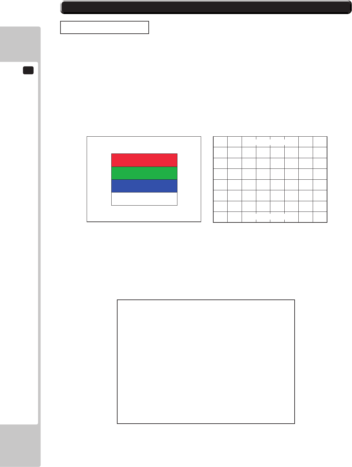
(1) C.R.T. TEST
In the TEST mode menu, selecting C.R.T. TEST allows the screen (on which the monitor is tested) to be displayed.
Although the monitor adjustments have been made at the time of shipment from the factory, make needed by
watching the test mode screen. If it is necessary, adjust the monitor by referring to Chapter 14.
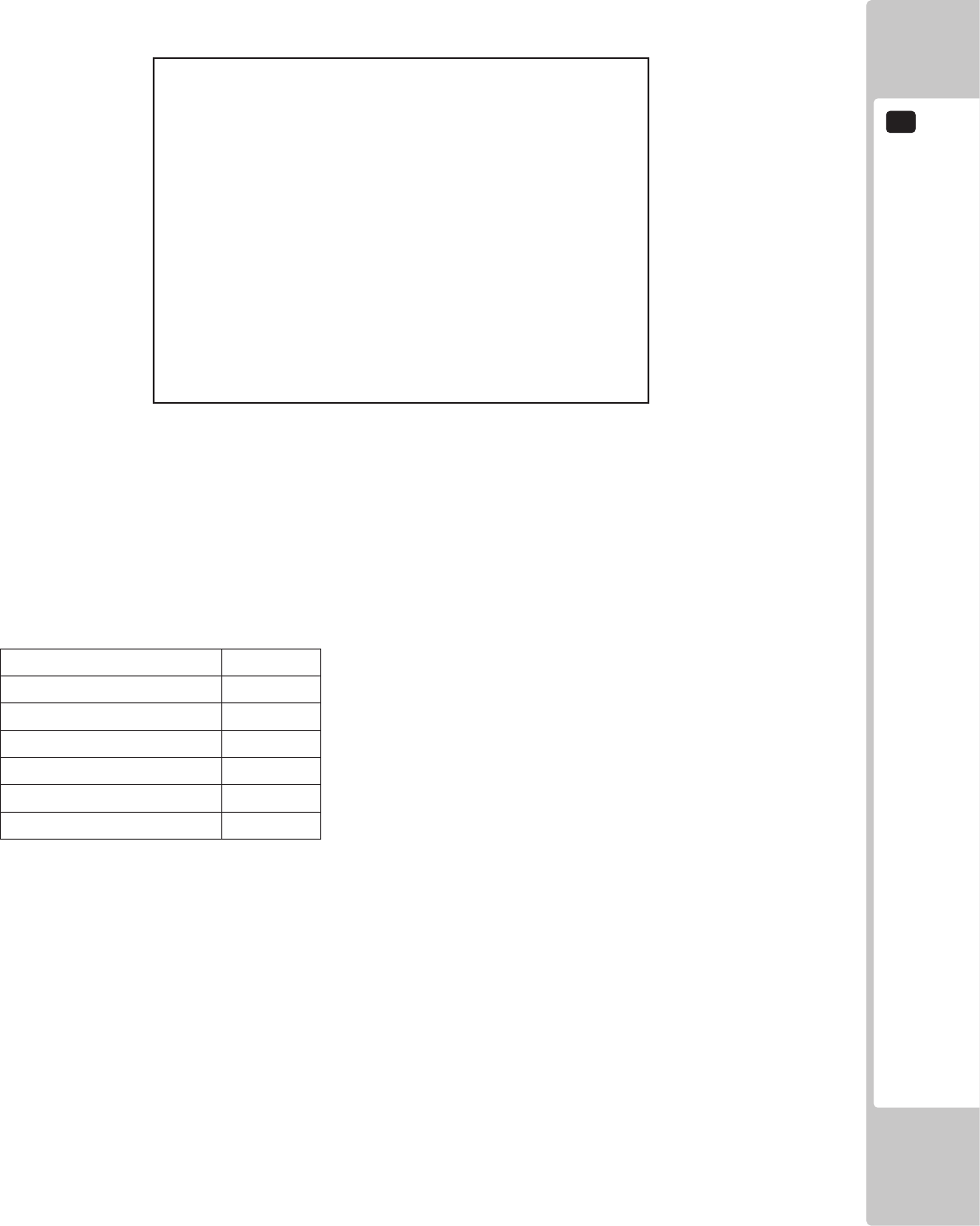
(2) INPUT TEST
Selecting the INPUT TEST on the game test mode menu screen (on which each switch is tested) to be displayed.
Press each switch. If the display beside each switch indicates “ON”, the switch and wiring connections are
satisfactory.
6-3 CHECKING ASSEMBLY (SETUP)
MONITOR TEST 2/2
PRESS TEST TO EXIT
MONITOR TEST 1/2
1 32
PRESS TEST TO NEXT
INPUT TEST
STEERING 00H
GAS 00H
BRAKE 00H
GEAR POSITION N
START OFF
VIEW CHANGE OFF
BOOST OFF
SERVICE OFF
TEST OFF
PRESS TEST AND SERVICE BUTTON TO EXIT
6-6 FIG. 01 6-6 FIG. 02
6-6 FIG. 03
ASSEMBLY AND INSTALLATION
6
23
(3) OUTPUT TEST
Select OUTPUT TEST from the menu in the test mode to cause the screen (on which each lamp is tested) to appear.
Ensure that lamp light up satisfactorily.
(4) SPEAKER TEST
Check to make sure the speakers are functioning properly using the SPEAKER TEST in SYSTEM TEST MODE.
This product makes use of the speakers as shown below. Set the RIGHT SPEAKER and LEFT SPEAKER to “ON”
and check to make sure that there is sound output.
6-6 TABLE 01
SPEAKER SETTING
RIGHT SPEAKER ON
LEFT SPEAKER ON
REAR RIGHT SPEAKER OFF
REAR LEFT SPEAKER OFF
CENTER SPEAKER OFF
WOOFER SPEAKER OFF
Perform the above inspections also at the time of monthly inspection.
6-6 FIG. 04
OUTPUT TEST
START BUTTON OFF
VIEW CHANGE BUTTON OFF
BOOST BUTTON OFF
RED LAMP 1 OFF
RED LAMP 2 OFF
BLUE LAMP 1 OFF
BLUE LAMP 2 OFF
-> EXIT
SELECT WITH SERVICE BUTTON
AND PRESS TEST BUTTON
6
ASSEMBLY AND INSTALLATION
24
SETTINGS AT TIME OF INSTALLATION
When2ormoregamemachinesaretobeinstalled,usetheGAMETESTMODEto
settheseatnumberforthecabinetandperformthesettingsforin-housematch-
ups.
Using TEST MODE, set, adjust and conrm the settings shown below. Refer to the LINDBERGH Service Manual
for details on SYSTEM TEST MODE and “9-3 GAME TEST MODE” for details on GAME TEST MODE.
● Perform the following settings in SYSTEM TEST MODE:
COIN ASSIGNMENTS
Set up the coin settings under COIN ASSIGNMENTS.
COIN CHUTE TYPE COMMON
SERVICE TYPE COMMON
NETWORK SETTING
Select the MAIN NETWORK and set up in the following manner:
DHCP DISABLE
There is no need to set a specic value for the IP address. Leave the displayed IP
address as is and exit the settings.
PRECAUTIONS WHEN MOVING THE MACHINE
7
25
PRECAUTIONS WHEN MOVING THE MACHINE
7
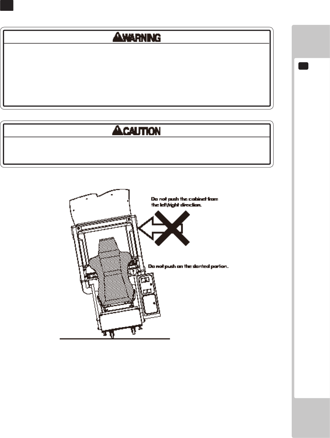
Donotpushonanypartsmadeofglass(e.g.CRTscreen)orplastic,astheseparts
maybreakandresultinbodilyinjury.
• Alwaysdisconnectthepowercablebeforemovingtheproduct.Ifitismoved
withthepowercableconnected,thecablecouldbedamaged,causingreor
electricshock.
• Donotpushthecabinetfromtheleft/rightwhenattemptingtomovetheunit.
Pushingfromthesidesmaycausetheunittotipandresultininjuryanddamage
toparts.
7 FIG. 01
7
PRECAUTIONS WHEN MOVING THE MACHINE
26

PLAYING THE GAME
1
27
GAME DESCRIPTION
8
8-1 GAME OVERVIEW
This product is a racing game set in real places.
Vehicles are equipped with an unlimited booster and drifts can be achieved by simply turning the steering wheel,
enabling anyone to enjoy street racing.
Choose from either one-player Single Player Mode or Versus Mode where 2 to 4 players can race at the same time.
Record personal data such as the cars you have earned, player name and best times using the R-Tuned Garage Card.
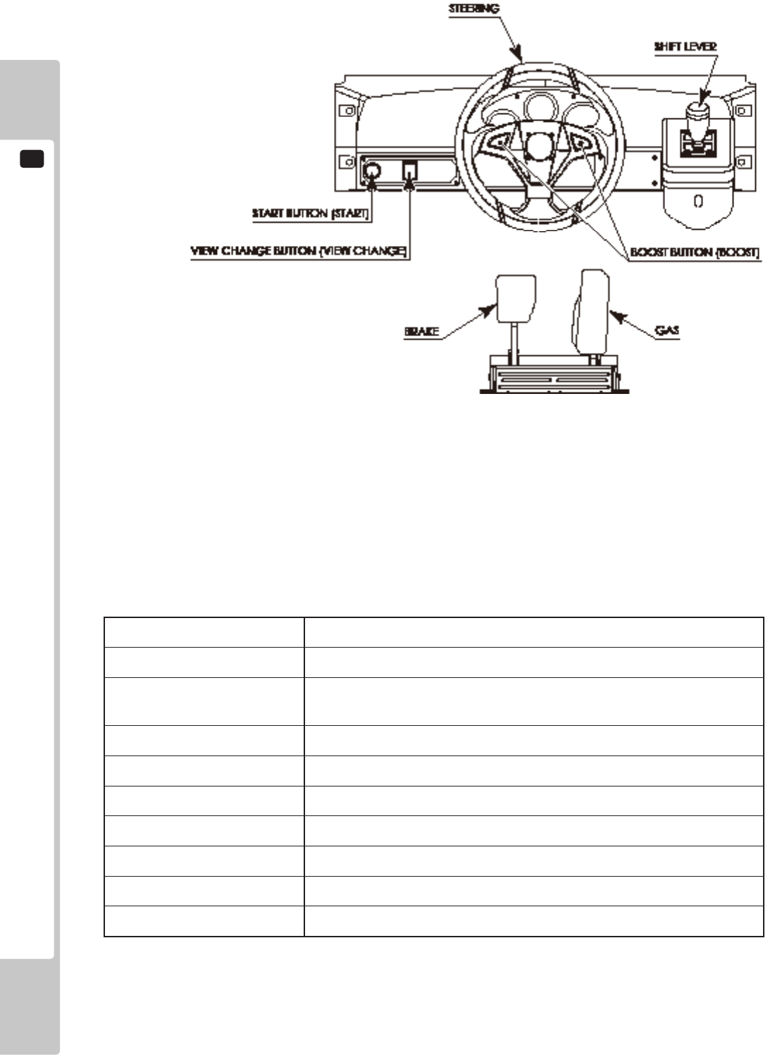
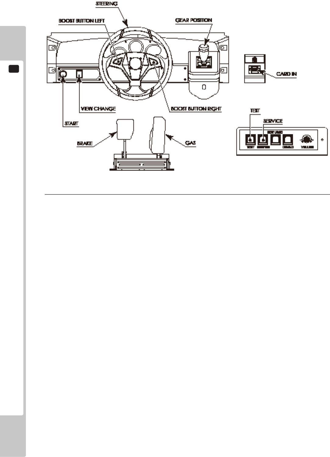
8-1-1 BASIC CONTROLS
● GAS
The car accelerates.
● BRAKE
The car decelerates and will stop if you continue to press the brake.
● STEERING
Changes the direction the car is going.
● BOOST BUTTON
Press down while moving to make the car accelerate rapidly.
There are 2 BOOST buttons on the left and the right of the steering wheel, each with the same function. The
resulting boost effect will be the same whether you press either button or both at the same time.
● SHIFT LEVER
Change gears when using manual transmission.
If you accelerate without using the shift lever for a certain period of time, the car will automatically switch to
automatic transmission.
● VIEW CHANGE BUTTON
Switch between 3 different views.
BOOST and Steering Wheel Vibration
Hold one of the BOOST buttons on the steering wheel to accelerate rapidly.
While boosting, the steering wheel will vibrate vigorously for an intense racing experience.
The level of steering wheel vibration can be set to NORMAL or LIGHT in Test Mode. See “8-3-8 FORCE
FEEDBACK” for more information about settings.
When starting the game, the player can voluntarily select either AGGRESSIVE (BOOST vibration ON) or MILD
(BOOST vibration OFF).
NOTE: BOOST can only be changed in Single Player Mode. The steering wheel response cannot be changed in
Versus Mode. It is automatically set to AGGRESSIVE. However, the MILD setting will be activated if you
insert a card with which you have previously played using the MILD setting in Single Player Mode.
1
PLAYING THE GAME
28
1-1-1 FIG. 01
8-1-2 CAR SELECTION
Choose from 20 models of popular Japanese and American cars.
1-1-2 TABLE 01
MAKE MODEL
TOYOTA SUPRA (JZA80), CELICA (ZZT231), CELICA (ST205)
NISSAN SKYLINE (BNR34), SKYLINE (BNR32), FAIRLADY Z (Z33),
FAIRLADY Z (Z32)
HONDA NSX (NA1), S2000 (AP1), INTEGRA (DC2)
MAZDA RX-7 (FD3S), RX-7 (FC3S), RX-8 (SE3P)
MITSUBISHI MOTORS LANCER EVOLUTION IX (CT9A), ECLIPSE (D32A)
SUBARU IMPREZA WRX (GC8), LEGACY B4 (BL5)
FORD MUSTANG (2006)
CHEVROLET CORVETTE (2005)
PONTIAC GTO (2004)
PLAYING THE GAME
1
29
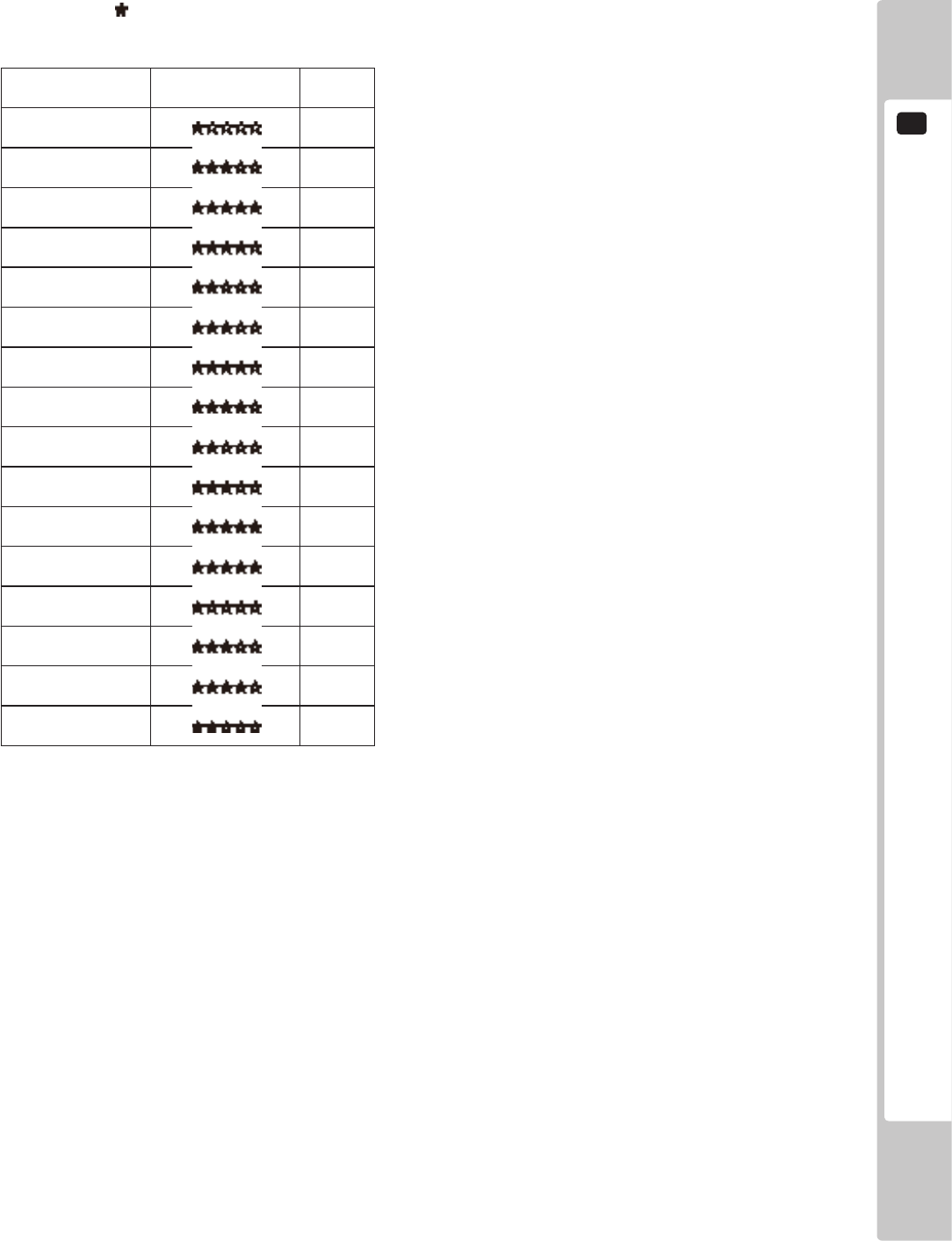
8-1-3 RACE COURSE
There are 4 areas with 4courses each, for a total of 16 courses. All courses are circuit tracks.
The more stars ( ) a course has, the higher its level of difculty.
1-1-3 TABLE 01
Course Name Difculty (1-5) Laps
Shinjuku A 5
Shinjuku B 3
Shinjuku C 3
Shinjuku D 3
Shibuya A 3
Shibuya B 3
Shibuya C 2
Shibuya D 5
Hong Kong A 4
Hong Kong B 2
Hong Kong C 2
Hong Kong D 2
New York A 5
New York B 3
New York C 2
New York D 4

1
PLAYING THE GAME
30
8-2 MODE OVERVIEW
8-2-1 SINGLE PLAYER MODE
Race against 3 computer-controlled rivals in this mode. You can win prize money depending on your results.
● Battle
Four players race simultaneously competing for the top position.
Scores are calculated based on your performance in the race, and the goal is to nish in rst place with the
highest score possible.
● Time Attack
Race alone and attempt to beat the times set by your 3 rivals.
The game will end if the time reaches zero.
Time is added when you pass a checkpoint or complete a lap.
Record the password displayed on the Result Screen and register it on the Internet to participate in the Internet
Ranking.
■ Rivals
Within each area there is one rare rival with more prize money than normal rivals.
In addition, there is a boss that will sometimes appear in any of the areas. You can receive even more prize
money against the boss.
■ Course Skill
Course Skill is a value that indicates your prociency at each course. It increases based on the results of battles
against your rivals.
As this value increases, your rivals also become stronger, but the prize money and score you can get will also
increase. One of the game’s objectives is to increase your Course Skill to MAX for every course.
8-2-2 VERSUS MODE
This mode allows players to compete against other machines in the same location.
Players win money based on results. Prize money varies depending on the of players competing.
When one player passes a checkpoint, time is added for all player.
When a player crosses the nish line, the remaining time for all other players will change to 10 seconds, and if they
cannot nish within 10 seconds, time will be up and the race will end.
When this happens, a player's nishing place will be determined by their position when time runs out.
■ Versus Win Total Display
You will receive a star ( ) each time you nish 1st in Versus Mode.
This will be displayed beneath your name during races to show your opponents how many times you have won.
1-2-2 FIG. 01
PLAYING THE GAME
1
31
8-3 HOW TO PLAY
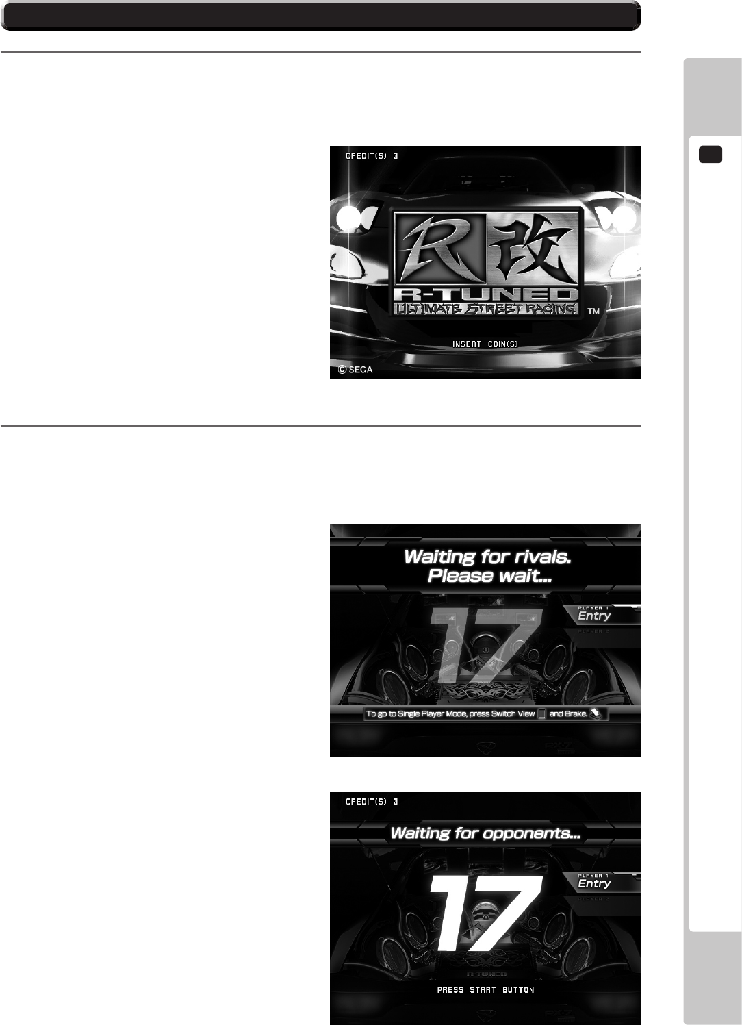
1
Insert coins. The game will start automatically when you have met the required amount of credits.
NOTE: If QUICK START is set to OFF in Test Mode, the game will not begin until the START button is pressed.
See 2-3-4 GAME ASSIGNMENTS for more information about QUICK START settings.
2
The game will wait for opponents from possible opponent machines not being played. Versus Mode will
begin if sufcient coins are inserted into another machine while you are waiting for opponents. The wait for
opponents will end when the countdown reaches zero or when the number of players reaches the set amount,
and the game will begin with the current number of waiting players. (Single Player Mode will begin if there
is one player.)
NOTE: You will not be taken to the waiting for
opponents screen if there is only a single
machine or the machine has not been set up for
Versus Mode.
■ How to Stop Waiting for Opponents
To go straight to Single Player Mode without
connecting with opponents, press the VIEW
CHANGE button and the Brake Pedal
simultaneously.
1-3 FIG. 01
1-3 FIG. 02
1-3 FIG. 03
1
PLAYING THE GAME
32
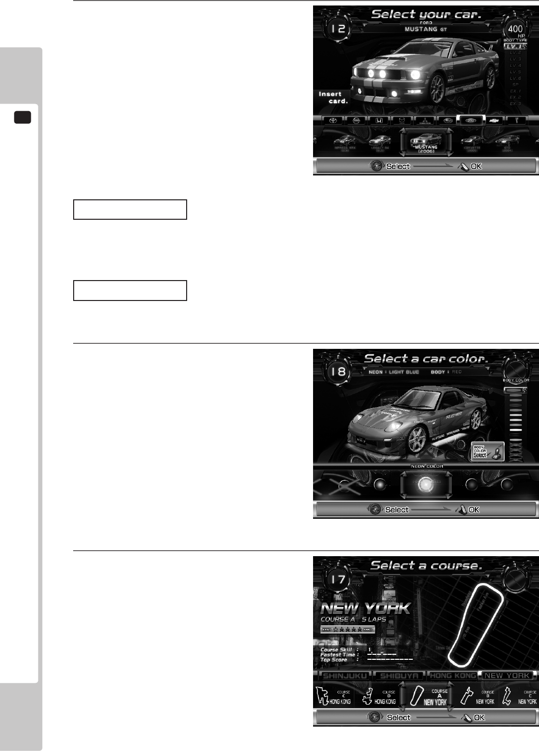
3
Select the car you will use. Use the steering
wheel to select the car and the shift lever to
choose the car level. Conrm your selection
with the Accelerator.
NOTE: The BOOST button can also be used to select
left and right, and the START button can be
used to conrm.
Inserting Card
If you want to use a “R-Tuned Garage Card/IC Card”, insert it while on the Car Selection Screen.
The card information will be shown with a conrmation window displaying “Use this card?.” Choose YES to use the
card.
Level Selection
When using a card, you can select the car level if you have earned cars.
The higher a car’s level, the greater the horsepower it will have and the ashier it will look.
4
Select the car body color and neon color
(undercarriage lights).
Choose the neon color using the steering wheel
or BOOST button and the body color using the
shift lever, then conrm your selection with the
Accelerator or the START button.
Colors crossed out by an “X” cannot be
selected. These can be used after meeting
certain conditions when using a card.
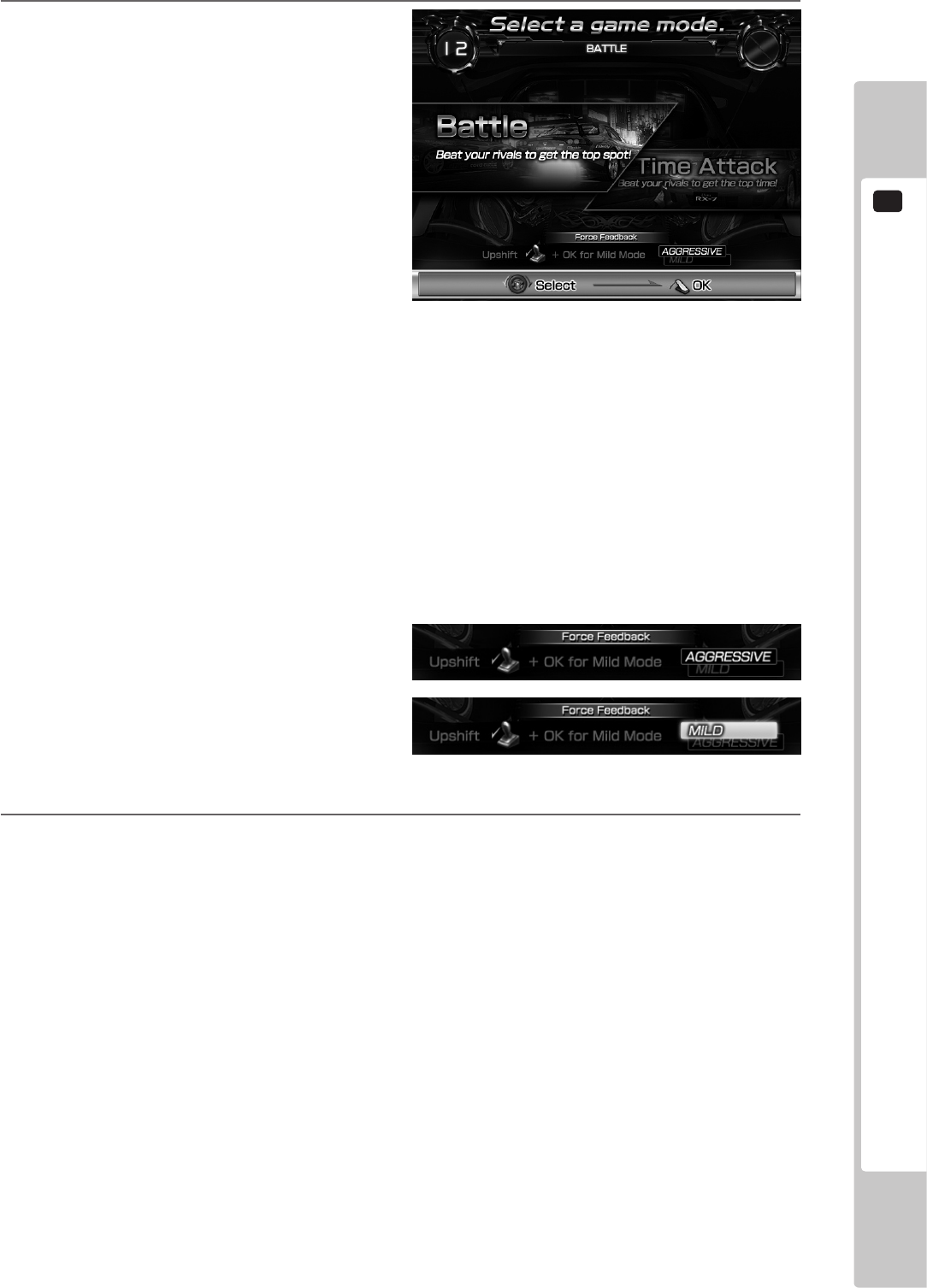
5
Select the course. Use the steering wheel to
select the course and conrm your selection
with the Accelerator.
NOTE: The BOOST buttons can also be used to select
left and right, and the START button can be
used to conrm.
In Versus Mode, course conrmation is decided
by the most votes. If 2 courses have the same
number of votes, then the course with the
lowest difculty rating will be chosen.
1-3 FIG. 05
1-3 FIG. 06
1-3 FIG. 04
PLAYING THE GAME
1
33
6
Select the game mode. Use the steering wheel
to select the mode and conrm your selection
with the Accelerator. (Only in Single Player
Mode.)
NOTE: The BOOST button can also be used to select
left and right, and the START button can be
used to conrm.
Push the shift lever up (forward) while on the Game Mode Selection Screen to change how the steering
wheel reacts when you press the BOOST button. (The steering wheel response cannot be changed in Versus
Mode. It is automatically set to AGGRESSIVE. However, the MILD setting will be activated if you insert a
card with which you have previously played using the MILD setting in Single Player Mode.)
NOTE: Releasing the lever will cause it to return to its original position. Conrm your selection while holding the
lever in place.
AGGRESSIVE: The steering wheel moves from left to right, giving you a dynamic controls experience.
MILD: Vibrations during boosting is set to OFF.
7
Various tutorials related to the game are displayed while the game is loading.
When the game starts, rst demo is shown, and then play begins.
1-3 FIG. 07
1-3 FIG. 08
1
PLAYING THE GAME
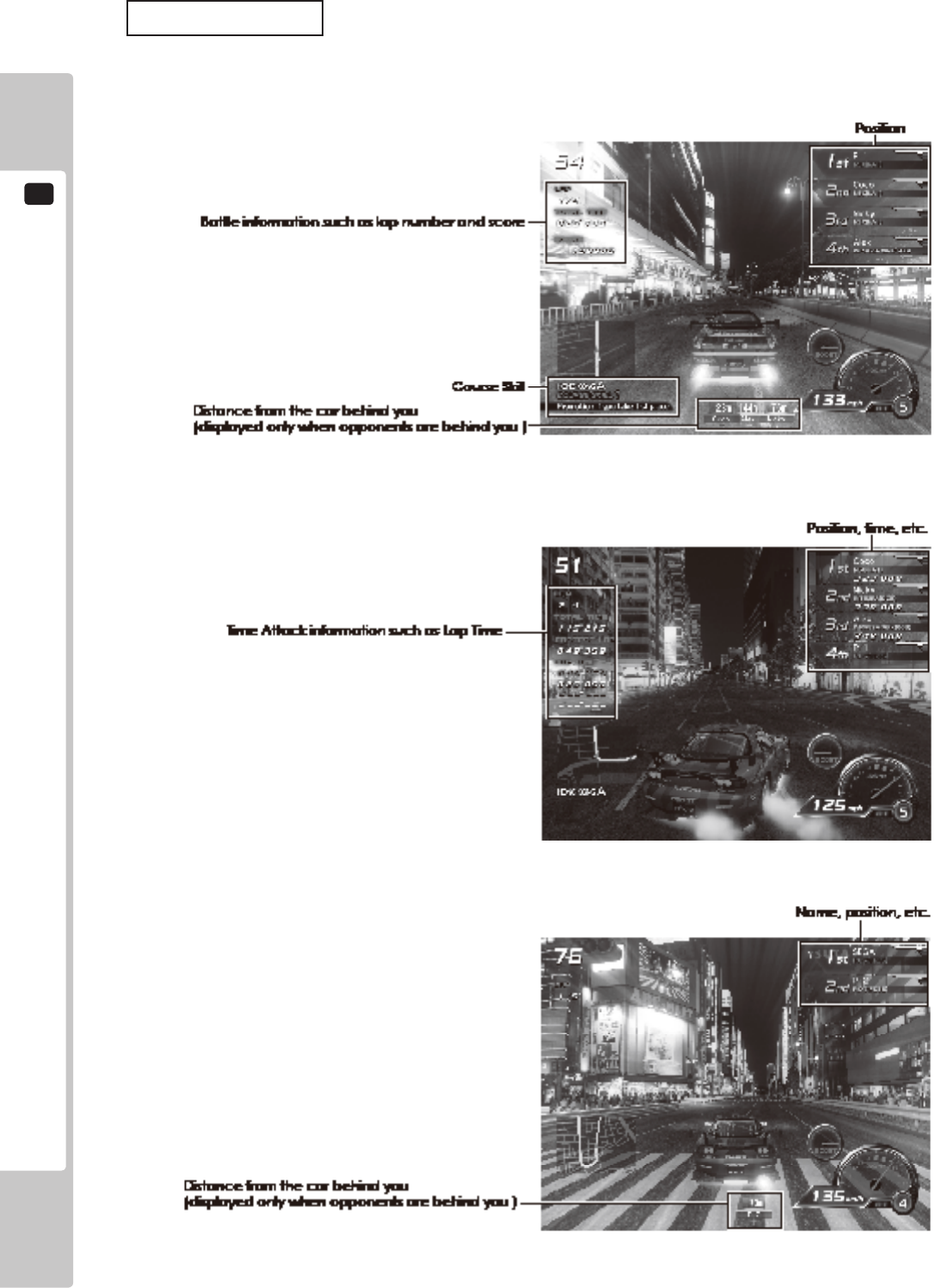
34
Game Screens
The content of the on-screen display is different for Single Player Mode (Battle), Single Player Mode (Time Attack)
and Versus Mode.
■ Single Player Mode (Battle)
■ Single Player Mode (Time Attack)
■ Versus Mode
1-3 FIG. 09
1-3 FIG. 10
1-3 FIG. 11
PLAYING THE GAME
1
35
Changing Between Automatic and Manual Transmission
This game employs a semi-automatic transmission system. Transmission is normally set to automatic (AT) but
the shift lever may be used to change gear during gameplay to change to manual transmission (MT). Additionally,
transmission can be set to MT from the outset by moving the shift lever during the pre-race countdown. If you
accelerate without using the shift lever for a certain period of time when using MT, the car will automatically switch
to automatic transmission.
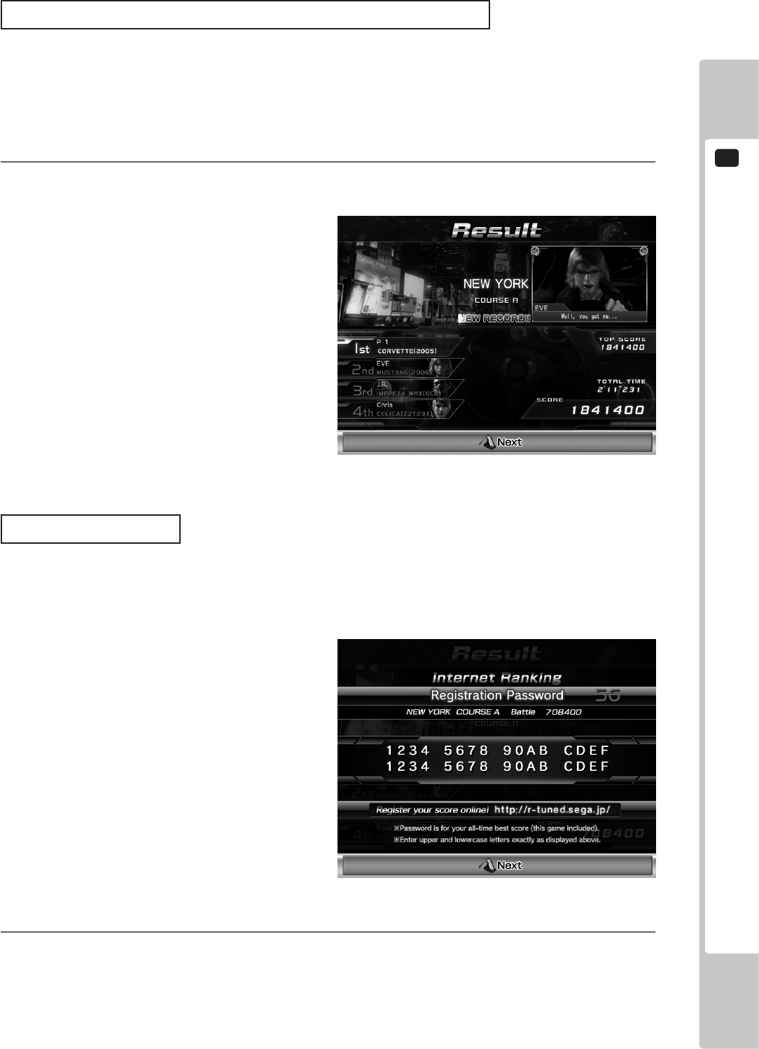
8
When the race is over, results will be displayed (Result Screen). The information displayed on-screen will
vary depending on the mode.
Internet Ranking
Follow the instructions on the Result Screen and press the VIEW CHANGE button. The “Best score for that course
saved on the card” will be displayed by a password. (A password will only be displayed when playing using a card.)
Register this password on the ofcial R-Tuned website (http://r-tuned.sega.jp) to participant in the Internet Ranking.
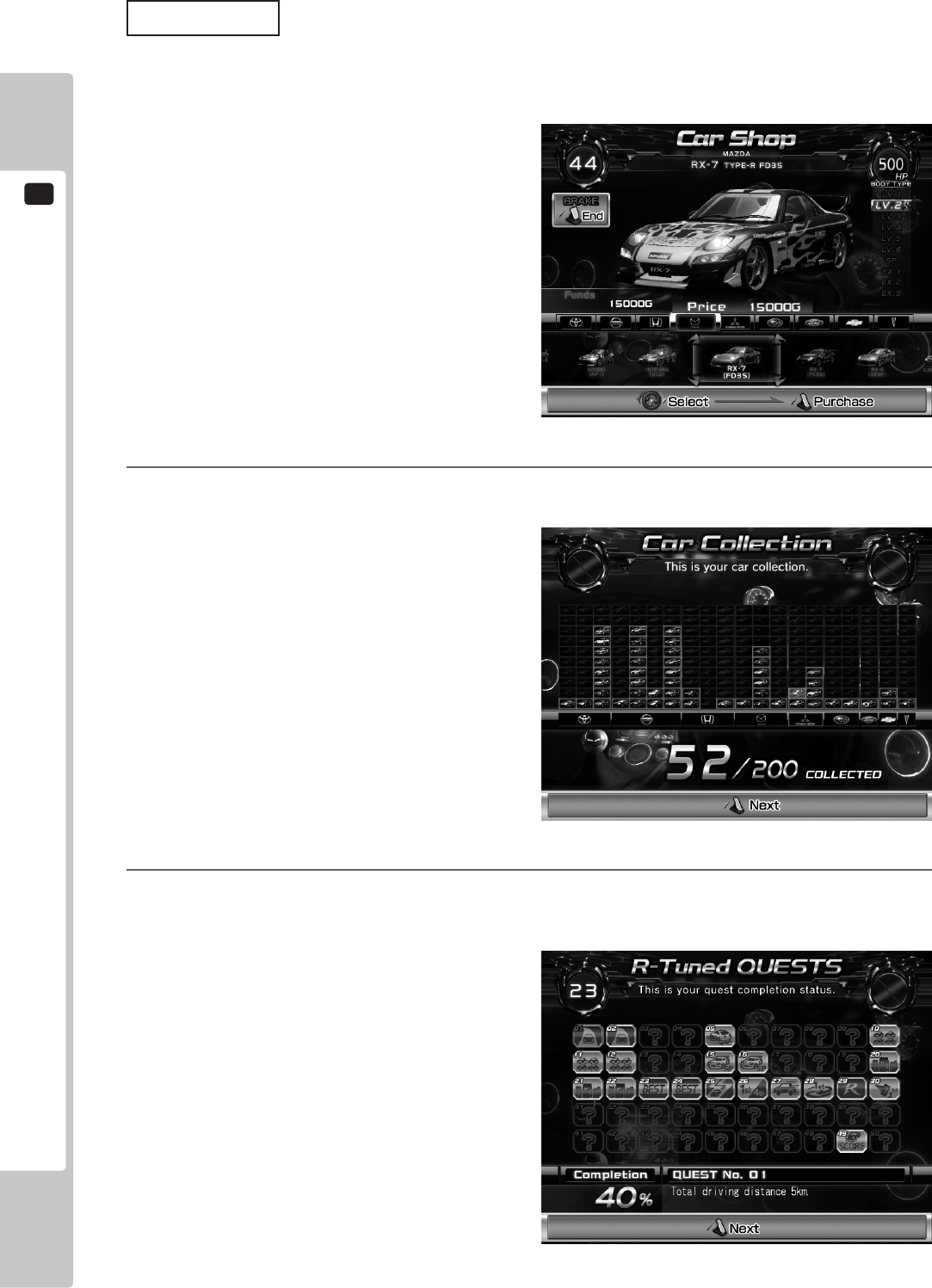
9
In Single Player Mode only, after a race is over you can use the prize money to buy new cars.
Use the steering wheel to select the car that you want to buy and step on the Accelerator to conrm your
choice. Stepping on the brake, will end the Shop Screen without purchasing anything.
NOTE: The BOOST button can also be used to select left and right, and the START button can be used to conrm.
1-3 FIG. 12
1-3 FIG. 13
1
PLAYING THE GAME
36
Car Levels
The higher a car’s level, the greater the horsepower it will have and the ashier it will look.
In the Car Shop you can buy cars one level up from your current car. However, you will be unable to buy cars of
some levels unless certain conditions have been met.
10
Your current car collection is displayed only in Single Player Mode. Use the accelerator to move to the next
car.
11
Your current quest completion status is displayed only in Single Player Mode. View the details of each quest
by selecting it with the steering wheel or shift lever. Use the accelerator to move to the next quest.
1-3 FIG. 14
1-3 FIG. 15
1-3 FIG. 16
PLAYING THE GAME
1
37
Quests
Quests are missions with conditions that must be met, such as “Take 1st Place on Shinjuku Course A.” There are 50
quests in total. If you meet the hidden clear conditions, the quest will be marked as “Complete.”
The completion of all quests is one of the objectives of the game.
Unlocking Limited Colors
When you complete specic quests, you will then be able to use previously unavailable body and neon colors.
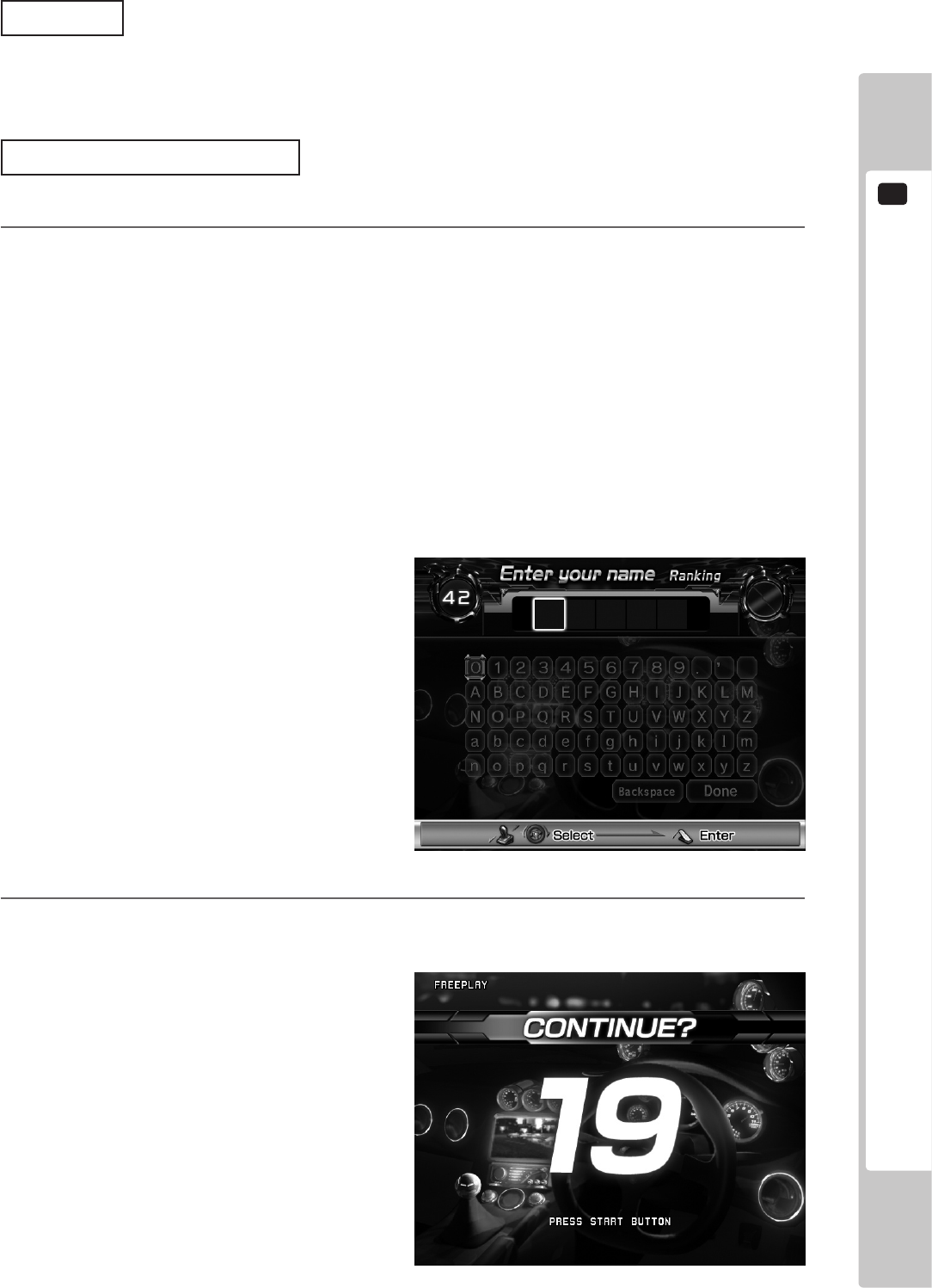
12
If you achieve a Ranking in Single Player Mode, you can enter your name. This name (5 English letters)
will be displayed on the advertising screen.
Additionally, when creating a new card, you can enter your name and save it to the card regardless of your
result. Enter up to 5 English letters or symbols.
If you achieve a Ranking when using a card, the name saved on the card will be the name displayed in the
Rankings.
NOTE: If LANGUAGE is set to JAPANESE in Test Mode, you can enter your name up to 5 hiragana characters,
katakana characters, symbols or English letters. See 9-3-4 GAME ASSIGNMENTS for more information
about LANGUAGE settings.
Use the steering wheel to move the cursor left and right and the shift bar to move the cursor up and down.
Conrm with the Accelerator or START button.
13
In Single Player Mode only, the Continue Screen will display “CONTINUE?” when the game is over.
Insert the required coins and press the START button to re-enter the Car Selection Screen and continue
playing.
1-3 FIG. 17
1-3 FIG. 18
1
PLAYING THE GAME
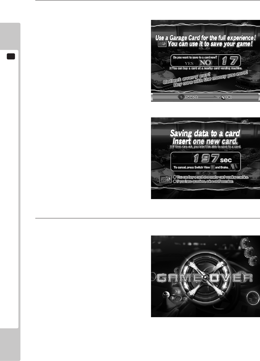
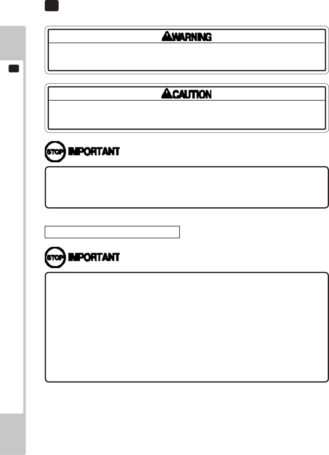
38
14
Even after a game ends, if you insert a new card, data from the game just played can be saved to the card.
To save your data to a card, follow the on-screen instructions and insert your new card.
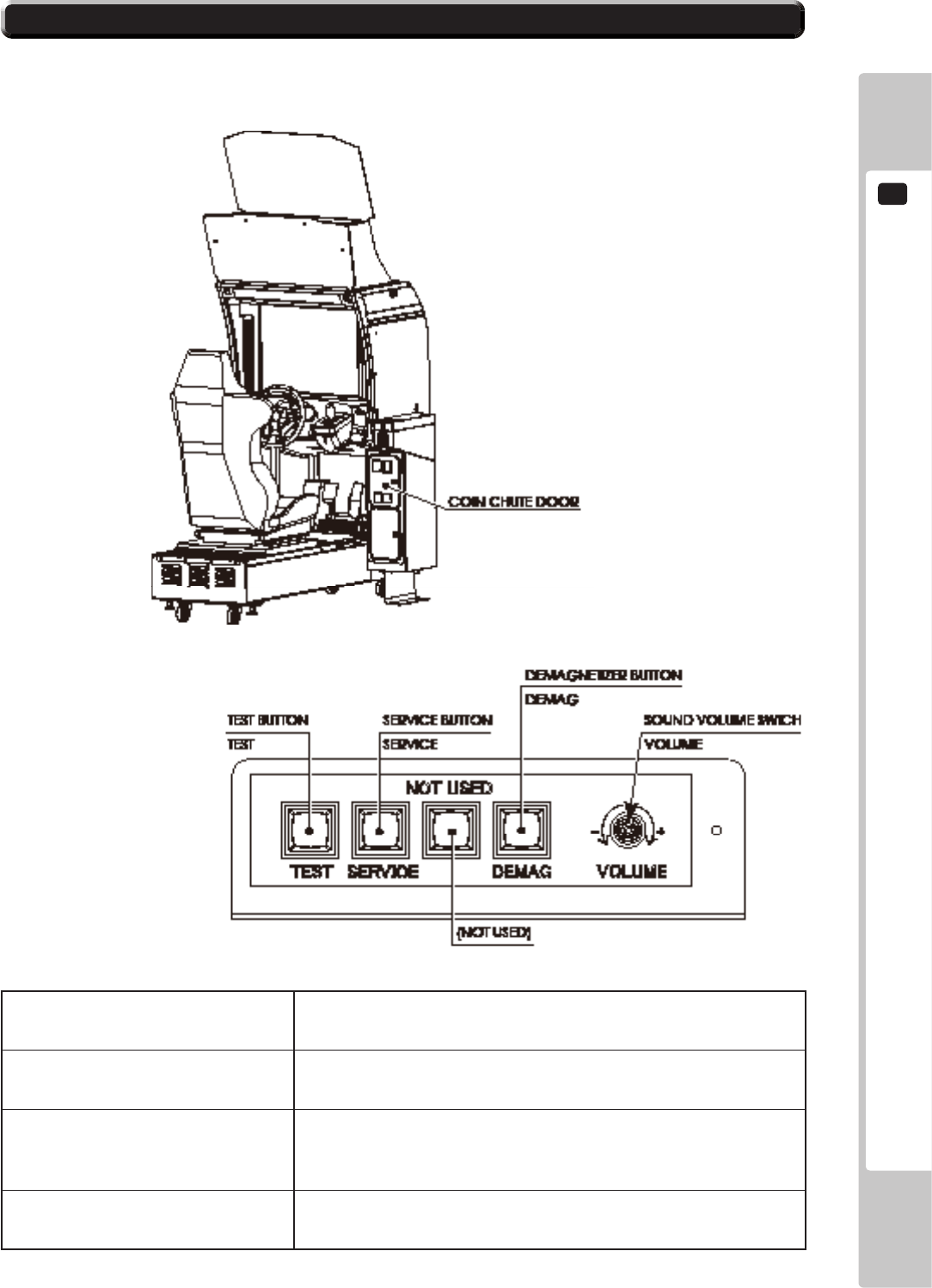
15
When either Single Player Mode or Versus Mode nish, the game is over. If you were using a card, it will be
ejected.
1-3 FIG. 19
1-3 FIG. 20
1-3 FIG. 21

PLAYING THE GAME
1
39
8-4 HINTS FOR PLAYING THE GAME
● BOOST
Hold the BOOST buttons to accelerate rapidly.
While pressed, the steering wheel will vibrate vigorously.
The BOOST buttons can be pressed an unlimited number of times, but you will lose a lot of time if you collide
with an opponent or a wall while using it.
● Drift
Turn the steering wheel dramatically before going into a turn to skid sideways (drift) through the turn. This
eliminates the need for braking.
The trick is to turn the steering wheel long before the corner, even when driving in a straight line.
If you use BOOST while drifting, you will lose control of the car and be unable to corner properly.
● High-Speed Drift
Pressing the accelerator just before or while drifting will carry out a “high-speed drift” from which it is very
difcult to decelerate. The sound of a high-speed drift is different from that of a standard drift.
● SLIP STREAM
It is possible to achieve a speed faster than the top speed of your car by following close behind an opponent.
When doing this, the word “SLIP STREAM” will be displayed above your speedometer.
2
TEST MODE
40
• WhenyouentertheTestMode,fractionalcoinandbonusadderdataiserased.
• Adjustthesoundtotheoptimumvolume,takingintoconsiderationthe
environmentalrequirementsoftheinstallationlocation.
TEST MODE
Becarefulthatangerorhanddoesnotgetcaughtwhenopening/closingthe
coinchutedoor.
Donottouchanypartsthatarenotspeciedinthesedirections.Touching
unspeciedlocationsmayleadtoelectricshockorcauseshortcircuits.
9
Caution when Initiating Test Mode
• Whenagameisnished(gameoverorgamecleared),thisproductproduces
ICcardssothattheycanbeusednormally.Forthisreason,ifTestModeis
enteredduringagame,theICcardwillbecomeunabletonishnormally,and
theresultsofthepreviousgamecannotbesaved.Itisthereforeimportantto
ensurethatnocustomersareplayingwhenenteringTestMode.Alsonotethat
thereisapossibilitythatanICcardmaybecomedamagedifTestModeis
enteredwhilethecardisbeingreadorwrittento.
• Whenmultiplecabinetsarelinked,enteringTestModeononeunitand
disconnectingtheLANcablewillcausetheothercabinetstowaitforallcurrent
gamesandthenstop.Notethatthesteeringwheelwillmoveatthistimeand
returntoitsdefault.
TEST MODE
2
41
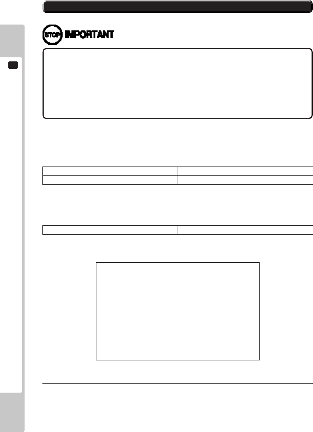
9-1 SWICH UNIT
In Test Mode, the switch unit in the coin chute door is operated.
Unlock and open the coin chute door. Inside is a switch unit.
TEST Button (TEST) Establishes Test Mode. Becomes the button to conrm selections in
Test Mode.
SERVICE Button (SERVICE) Makes it possible to enter credits for service without increasing the
coin meter. Becomes the button to select items in Test Mode.
DEMAGNETIZER Button (DEMAG) Eliminates the on-screen color unevenness due to magnetization
of CRT. First use this SW before performing the monitor's color
adjustment.
Sound Volume Switch (VOLUME) This is the volume knob for speakers at the left and right of the
control panel. Turn the knob to the right to increase speaker volume.
2-1 FIG. 01
2-1 FIG. 02 SWICH UNIT
2
TEST MODE
42
9-2 SYSTEM TEST MODE
• RefertoBOOKKEEPINGinGAMETESTMODEforthisproduct’sdata.
• Adjustforanappropriatesoundvolumeinconsiderationoftheinstallationsite.
• RemovingtheCoinMetercircuitryrendersthegameinoperable.
• ReadtheLINDBERGHServiceManualincludedwiththeproductfordetails
aboutSystemTestMode.However,thesettingsforthisproductshouldfollowthe
specicationsinthismanual.
System Test Mode can be used to check that the main circuit operations are correct, adjust Monitor and perform
coin/credit settings etc. Read the LINDBERGH Service Manual for details.
However, this product can only be used with the settings shown below.
COIN ASSIGNMENTS
COIN CHUTE TYPE COMMON
SERVICE TYPE COMMON
NOTE: When installing this title, the default setting of GAME COST SETTING is 1CREDIT TO START and
1CREDIT TO CONTINUE.
NETWORK SETTING
DHCP DISABLE
1
When the TEST Button is pressed, the System Test Menu Screen appears.
2
Use the SERVICE Button to move the cursor to the desired test item.
3
Press the TEST Button to conrm selection of the item.
SYSTEM TEST MENU
SYSTEM INFORMATION
STORAGE INFORMATION
JVS TEST
MONITOR TEST
SPEAKER TEST
COIN ASSIGNMENTS
CLOCK SETTING
NETWORK SETTING
GAME TEST MODE
-
> EXIT
SELECT WITH SERVICE AND PRESS TEST
2-2 FIG. 01
TEST MODE
2
43
9-3 GAME TEST MODE
• TochangesettingsintheGameTestMode,simplymakingchangesonthe
settingscreenwillnotbeeffective.CompletetheTestModeinnormalfashion.
• Usewiththespeciedsettings.Ifsettingsotherthanthosespeciedareused,
inappropriateoperationsormalfunctionmayoccur.
9-3-1 GAME TEST MODE
1
Select GAME TEST MODE from the System Test Menu Screen to display the Game Test Mode Screen as
follows.
NOTE: This game’s Screen Display Safe Areas (areas that deal with crucial game menus and text, PL displays etc.)
are denoted by white lines. Adjust the monitor so that the top, bottom, left and right white lines are displayed
within the screen. Refer to the Owner’s Manual included with the cabinet for further information on how to
adjust the monitor.
R-Tuned
GAME TEST MODE
INPUT TEST
OUTPUT TEST
GAME ASSIGNMENTS
LINK SETTING
GAME SYSTEM INFORMATION
CARD R/W TEST
FORCE FEEDBACK
STEER ADJUSTMENT
CLOSE SETTING
IC CARD CHECK
BOOKKEEPING
BACKUP DATA CLEAR
-
> EXIT
SELECT WITH SERVICE BUTTON AND PRESS TEST BUTTON
2-3-1 FIG. 01
4
When testing and checking are completed, select EXIT and press the TEST Button. The System Test Menu
Screen reappears.
5
When all tests are completed, select EXIT and press the TEST Button. The Game Screen reappears.
2
TEST MODE
44
2
For each following item, a test or setting is implemented, or data is displayed.
INPUT TEST Tests each input device used for game.
OUTPUT TEST Tests each output device used for game.
GAME ASSIGNMENTS Adjusts all game settings.
LINK SETTING Adjusts settings used when multiple cabinets are connected.
GAME SYSTEM INFORMATION View information about the game.
CARD R/W TEST Tests the card reader/writer.
Not displayed when the CARD SYSTEM is OFF. See “2-3-4 GAME
ASSIGNMENTS” for more information about CARD SYSTEM
settings.
FORCE FEEDBACK Set the STEERING resistance.
STEER ADJUSTMENT Adjusts the STEERING.
CLOSE SETTING Premises closing setting.
Only displayed on the cabinet for which the LINK ID is set to 1.
These settings are applied to all other connected cabinets. See “2-3-5
LINK SETTING” for more information about LINK ID settings.
Not displayed when the CARD SYSTEM is OFF. See “2-3-4 GAME
ASSIGNMENTS” for more information about CARD SYSTEM
settings.
IC CARD CHECK View the contents of an IC card.
Not displayed when the CARD SYSTEM is OFF. See “2-3-4 GAME
ASSIGNMENTS” for more information about CARD SYSTEM
settings.
BOOKKEEPING Displays all recorded game data.
BACKUP DATA CLEAR Erases all types of game records.
3
Use the SERVICE Button to move the cursor to the desired test item. Press the TEST Button to select the
test item.
4
After changing the settings, select EXIT and press the TEST Button to return to the Game Test Menu
Screen.
5
On the GAME TEST MODE screen, select EXIT and press the TEST Button. The SYSTEM TEST MENU
screen reappears.
6
On the SYSTEM TEST MENU screen, select EXIT and press the TEST Button. The game screen reappears.
TEST MODE
2
45
9-3-2 INPUT TEST
Select INPUT TEST to display the following screen and check the status of input devices.
This test should be used periodically to check that each input device is functioning correctly.
1
On the GAME TEST MODE screen, select INPUT TEST and press the TEST Button. The INPUT TEST
screen appears.
2
Manipulate each switch, etc., to check screen display.
Test the STEERING, GAS and BRAKE controls to ensure that they are functioning properly and that the
parameters change smoothly as each input device is operated. The STEERING value will decrease when the
steering wheel is turned to the left and increase when turned to the right.
Display N, UP and DOWN using the GEAR POSITION. N should display there is no control input. Verify
that both UP and DOWN display in sync with the position of the gear shifter.
CARD IN will change to ON when a card is inserted.
Not displayed when the CARD SYSTEM is OFF. See “9-3-4 GAME ASSIGNMENTS” for more
information about CARD SYSTEM settings.
Other controls are working properly if the OFF display changes to ON when operating the corresponding
input device.
2-3-2 FIG. 01
INPUT TEST
STEERING **H
GAS **H
BRAKE **H
BOOST BUTTON LEFT OFF
BOOST BUTTON RIGHT OFF
GEAR POSITION N
START OFF
VIEW CHANGE OFF
CARD IN OFF
SERVICE OFF
TEST OFF
SELECT WITH SERVICE BUTTON AND PRESS TEST BUTTON
2
TEST MODE
46
2-3-2 FIG. 02
3
When all checks are completed, press the TEST Button and the SERVICE Button simultaneously. The
GAME TEST MODE screen reappears.
TEST MODE
2
47
9-3-3 OUTPUT TEST
This screen is for conrming the proper operation of each output device used by the game.
Periodically use this screen to check the status of each output device.
The items that can be tested vary depending on the CABINET TYPE. See “9-3-4 GAME ASSIGNMENTS” for
more information about CABINET TYPE settings.
1
On the GAME TEST MODE screen, select OUTPUT TEST and press the TEST Button. The OUTPUT
TEST screen appears.
OUTPUT TEST
START BUTTON LAMP OFF
VIEW BUTTON LAMP OFF
RED LAMP LEFT OFF
RED LAMP RIGHT OFF
BLUE LAMP LEFT OFF
BLUE LAMP RIGHT OFF
BOOST LAMP RED OFF
BOOST LAMP GREEN OFF
BOOST LAMP BLUE OFF
CARD LOCK OFF
-
> EXIT
SELECT WITH SERVICE BUTTON AND PRESS TEST BUTTON
The BLUE LAMPS and RED LAMPS are located within the billboard box.
2-3-3 FIG. 01 CONVERT
2-3-3 FIG. 02
2
TEST MODE
48
OUTPUT TEST
START BUTTON LAMP OFF
VIEW BUTTON LAMP OFF
SIDE LAMP RED OFF
SIDE LAMP GREEN OFF
SIDE LAMP BLUE OFF
BOOST LAMP RED OFF
BOOST LAMP GREEN OFF
BOOST LAMP BLUE OFF
SPEAKER LAMP RED OFF
SPEAKER LAMP GREEN OFF
SPEAKER LAMP BLUE OFF
CARD LOCK OFF
-
> EXIT
SELECT WITH SERVICE BUTTON AND PRESS TEST BUTTON
2-3-3 FIG. 03 ORIGINAL
2
Each item is explained below.
Select CARD LOCK and press the TEST Button to turn it ON. The card reader/writer locking mechanism
will activate. Press the TEST Button again to release the locking mechanism and turn it OFF.
Not displayed when the CARD SYSTEM is OFF. See “9-3-4 GAME ASSIGNMENTS” for more
information about CARD SYSTEM settings.
As for all other options, press the TEST Button on an item to change the condition to ON, turning on its
indicator light. Press the TEST Button again to change the condition to OFF, turning off the light.
3
Press the SERVICE Button and move the cursor to select the item (output device).
4
When all checks are completed, select EXIT and press the TEST Button. The GAME TEST MODE screen
reappears.
TEST MODE
2
49
9-3-4 GAME ASSIGNMENTS
All settings such as level of game difculty are adjusted.
Setting changes do not become effective until EXIT has been selected on the GAME TEST MODE screen. After a
setting has been changed, be sure to always exit the GAME TEST MODE.
Only displayed on the cabinet for which the LINK ID is set to 1. These settings are applied to all other connected
cabinets. See “9-3-5 LINK SETTING” for more information about LINK ID settings.
1
On the GAME TEST MODE screen, select GAME ASSIGNMENTS and press the TEST Button. The
GAME ASSIGNMENTS screen appears.
GAME ASSIGNMENTS
DIFFICULTY NORMAL
ADVERTISE SOUND ON
SPEEDOMETER KM/H
QUICK START ON
LANGUAGE ENGLISH
CARD SYSTEM ON
CABINET TYPE ORIGINAL
DEFAULT SETTING
-
> EXIT
SELECT WITH SERVICE BUTTON AND PRESS TEST BUTTON
2-3-4 FIG. 01
2
Each item is explained below.
DIFFICULTY Set level of difculty to one of ve levels; VERY EASY → EASY → NORMAL →
HARD → VERY HARD.
VERY EASY is the easiest, and VERY HARD is the most difcult. (Default setting:
NORMAL)
NOTE: Only displayed on the cabinet for which the LINK ID is set to 1.
ADVERTISE SOUND Set sound on the advertising screen. (Default setting: ON)
SPEEDOMETER Set the speedometer to display speed in kilometers per hour (KM/H) or miles per
hour (MPH). (Default setting: KM/H)
QUICK START Set game to start automatically when the required number of credits is inserted.
(Default setting: ON)
NOTE: Only displayed on the cabinet for which the LINK ID is set to 1.
The game will only begin automatically when sufcient credits are inserted During
the advertising screen.
LANGUAGE Set either Japanese (JAPANESE) or English (ENGLISH) as the display language.
(Default setting: ENGLISH)
CARD SYSTEM Set whether or not to use the card reader/writer. (Default setting: ON).
CABINET TYPE Set whether you are using an R-Tuned original cabinet (ORIGINAL) or a converted
cabinet (CONVERT). (Default setting: ORIGINAL)
DEFAULT SETTING Restore all GAME ASSIGNMENTS settings to default.
3
Use the SERVICE Button to move the cursor to the desired test item. Press the TEST Button to select the
test item.
4
When all setting adjustments are completed, select EXIT and press the TEST Button. The GAME TEST
MODE screen reappears.
2
TEST MODE
50
• Ensurethatyousetupeachcabinetcorrectly.Incorrectsettingscanleadto
malfunctions.
• PlayersusingcabinetswithlowerLINKIDnumbersstartfurthertotheleftin“Versus
Mode.”Whenpositioningcabinets,ensurethatyouarrangethemsothatthe
LINKIDnumbersincreasefromlefttoright.
• Whenmultiplecabinetsarelinked,enteringTestModeononeunitand
disconnectingtheLANcablewillcausetheothercabinetstowaitforallcurrent
gamesandthenstop.Notethatthesteeringwheelwillmoveatthistimeand
returntoitsdefault.
9-3-5 LINK SETTING
Set which cabinets to link when multiple cabinets are operating.
1
On the GAME TEST MODE screen, select LINK SETTING and press the TEST Button. The LINK
SETTING screen appears.
LINK SETTING
LINK ID 1
TOTAL MACHINE 1
GROUP 1
DEFAULT SETTING
-
> EXIT
SELECT WITH SERVICE BUTTON AND PRESS TEST BUTTON
2-3-5 FIG. 01
2
Each item is explained below.
LINK ID Assign an ID to the cabinet. Choose from 1, 2, 3 or 4. (Default setting: 1).
TOTAL MACHINE Set how many cabinets can play. Set a number 1, 2, 3 or 4 depending on the total
number of units connected. (Default setting: 1)
Set the cabinet to 1 if it is not for Versus Mode.
GROUP Select 1, 2, 3 or 4 when it is necessary to divide cabinets into groups. Cabinets set in
the same group are linked and can play in Versus Mode. (Default setting: 1)
DEFAULT SETTING Restore all LINK SETTING settings to default.
TEST MODE
2
51
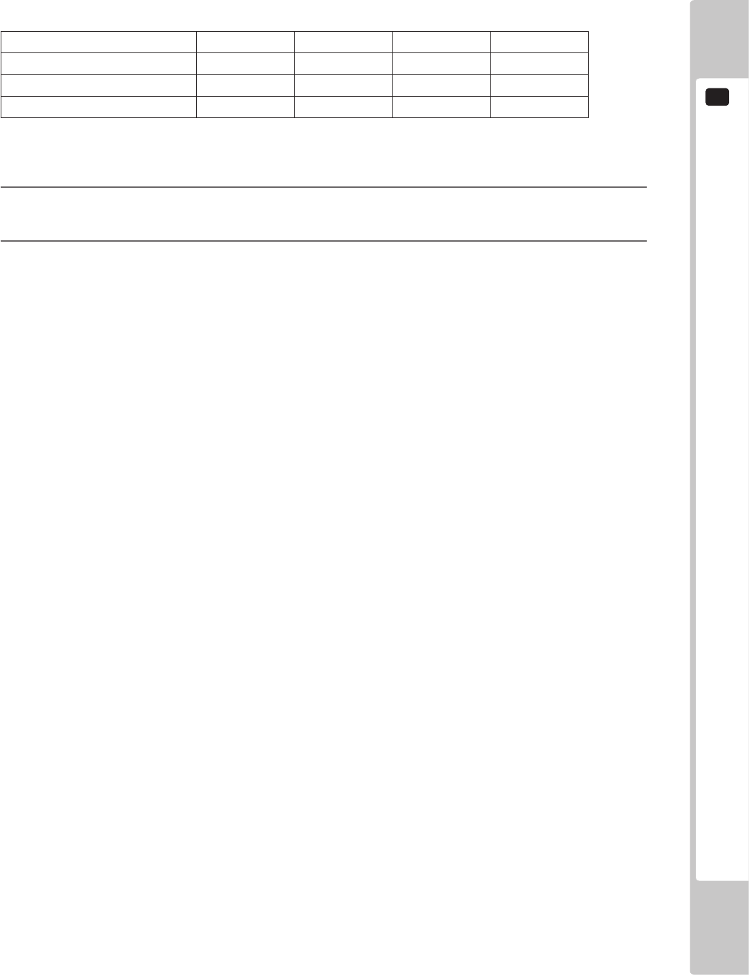
Example Settings
Below are the settings that would be used when 4 cabinets are connected where cabinet A is for exclusively for
Single Player Mode and cabinets B, C and D can be used for Versus Mode.
Cabinet A Cabinet B Cabinet C Cabinet D
LINK ID Setting 1 1 2 3
TOTAL MACHINE Setting 1 3 3 3
GROUP Setting 1 2 2 2
When the race starts in Versus Mode, cabinet B will be on the left, cabinet C in the middle and cabinet D on the
right.
3
Use the SERVICE Button to move the cursor to the desired test item. Press the TEST Button to select the
test item.
4
When all setting adjustments are completed, select EXIT and press the TEST Button. The GAME TEST
MODE screen reappears.
2
TEST MODE
52
9-3-6 GAME SYSTEM INFORMATION
View information about the game.
1
On the GAME TEST MODE screen, select GAME SYSTEM INFORMATION and press the TEST Button.
The GAME SYSTEM INFORMATION screen appears.
GAME SYSTEM INFORMATION
TITLE: R-Tuned
DATE: ****-**-**T**:**:**
VERSION: *.***
-
> EXIT
PRESS TEST BUTTON TO EXIT
2-3-6 FIG. 01
2
Press the TEST Button again to return to the GAME TEST MODE screen.
TEST MODE
2
53
9-3-7 FORCE FEEDBACK
WhenFORCEFEEDBACKisselected,“Initializekickback...”willbedisplayedand
thesteeringwheelwillrotate.MakesurethatnooneistouchingtheSTEERING
beforerunningthesetestsascontactmaycauseinjury.
Sets the strength of vibration, reaction, and resistance of the steering wheel.
1
Select FORCE FEEDBACK on the GAME TEST MODE screen and press the TEST Button.
The next screen is displayed and initialization of the drive board is carried out. Do not touch the steering
wheel during this time.
FORCE FEEDBACK
Initialize kickback ...
Please DO NOT touch the steering wheel.
2-3-8 FIG. 01
2
TEST MODE
54
2
The FORCE FEEDBACK screen is displayed when the drive board initialization is complete.
FORCE FEEDBACK
FORCE NORMAL
FORCE TEST
CENTER OFF
LEFT OFF
RIGHT OFF
-
> EXIT
SELECT WITH SERVICE BUTTON AND PRESS TEST BUTTON
2-3-8 FIG. 02
3
Each item is explained below.
FORCE Set the strength required to turn the steering wheel to NORMAL or LIGHT. (Default
setting: NORMAL)
FORCE TEST Apply force to the steering wheel to check its movement.
Turn the steering wheel left and right when the screen indicates LEFT and RIGHT. When
CENTER is displayed, the steering wheel will return to the center.
4
Use the SERVICE Button to move the cursor to the desired test item. Press the TEST Button to select the
test item.
5
When all setting adjustments are completed, select EXIT and press the TEST Button. The GAME TEST
MODE screen reappears.
TEST MODE
2
55
9-3-8 STEER ADJUSTMENTS
Calibrate the standard steering settings to be used in the game.
1
On the GAME TEST MODE screen, select STEER ADJUSTMENTS and press the TEST Button. The
STEER ADJUSTMENTS screen appears.
STEER ADJUSTMENTS
(MIN -40: MAX 40)
STEERING = *** o
^
CENTER
LEFT
RIGHT
-
> EXIT
SELECT WITH SERVICE BUTTON AND PRESS TEST BUTTON
2-3-9 FIG. 01
2
Center the steering wheel.
If the “o” is not in line with the middle of the “^” above the word CENTER, press the SERVICE Button and
align the cursor with either LEFT or RIGHT and press the TEST Button to move the “^” until it is directly
below the “o.”
Aligning the cursor with RIGHT and pressing the TEST Button will cause the “^” to slide to the right.
Aligning the cursor with LEFT and pressing the TEST Button will cause the “^” to slide to the left.
3
When you have nished calibrating the steering wheel, select EXIT and press the TEST Button to return to
the GAME TEST MODE screen.

2
TEST MODE
56
9-3-9 CLOSE SETTING
EnsurethatyouhavepreviouslyadjustedthetimesettingsinSystemTestMode.
Closesettingswillnotfunctioncorrectlyifthecabinet’stimesettingsareincorrect.
Checkthetimesettingsofeachindividualcabinetifmultipleunitsareconnected.
RefertotheLINDBERGHServiceManualfordetailsregardingtimesettings.
Set closing time settings.
A notication that the service is coming to an end is displayed 15 minutes before the set closing time, and cards will
stop being accepted from 10 minutes before the time. The option to continue is not offered if playing with a card.
1
On the GAME TEST MODE screen, select CLOSE SETTING and press the TEST Button. The CLOSE
SETTING screen appears.
CLOSE SETTING
SCHEDULE TYPE DAY
HOURS 24
MINUTES 00
DEFAULT SETTING
-
> EXIT
SELECT WITH SERVICE BUTTON AND PRESS TEST BUTTON
2-3-10 FIG. 01
TEST MODE
2
57
CLOSE SETTING
SCHEDULE TYPE WEEK
(Sun) HOURS 24
MINUTES 00
(Mon) HOURS 24
MINUTES 00
(Tue) HOURS 24
MINUTES 00
(Wed) HOURS 24
MINUTES 00
(Thu) HOURS 24
MINUTES 00
(Fri) HOURS 24
MINUTES 00
(Sat) HOURS 24
MINUTES 00
DEFAULT SETTING
-
> EXIT
SELECT WITH SERVICE BUTTON AND PRESS TEST BUTTON
2-3-10 FIG. 02
2
Each item is explained below.
SCHEDULE TYPE Can be set by the day (DAY) or by the week (WEEK). (Default setting: DAY)
When DAY is selected, the closing time will be set at the same time every day.
When WEEK is selected, the closing time can be set differently for each day.
HOURS Set the “HOURS” for the closing time. (Default setting: 24)
Either set a time from 18:00 to 30:00 (6am) or select ALL TIME.
24 → 25 → 26 → 27 → 28 → 29 → 30 → ALL TIME → 18 → 19 → 20 → 21 →
22 → 23 → 24...
Setting ALL TIME will mean a Card can be used 24 hours a day.
MINUTES Set the “MINUTES” for the closing time. (Default setting: 00)
Adjust in 5 minute increments.
00 → 05 → 10 → 15 → ... → 50 → 55 → 00...
This option will not be displayed if the HOURS item has been set to ALL TIME.
DEFAULT SETTING Restore all CLOSE SETTING settings to their default.
3
Use the SERVICE Button to move the cursor to the desired test item. Press the TEST Button to select the
test item.
4
When all setting adjustments are completed, select EXIT and press the TEST Button. The GAME TEST
MODE screen reappears.
2
TEST MODE
58
9-3-10 BOOKKEEPING
Each game record can be viewed.
1
On the GAME TEST MODE screen, select BOOKKEEPING and press the TEST Button. The
BOOKKEEPING 1/2 screen appears.
BOOKKEEPING 1/2
COIN 1 *
COIN 2 *
TOTAL COINS *
COIN CREDITS *
SERVICE CREDITS *
TOTAL CREDITS *
PRESS TEST BUTTON TO CONTINUE
2-3-12 FIG. 01
2
Each item is explained below.
COIN 1 Number of coins inserted in coin chute 1.
COIN 2 Number of coins inserted in coin chute 2.
TOTAL COINS Total number of coins inserted in all coin chutes.
COIN CREDITS Number of credits for coins inserted.
SERVICE CREDITS Number of credits entered with the SERVICE Button.
TOTAL CREDITS Total number of all credits.
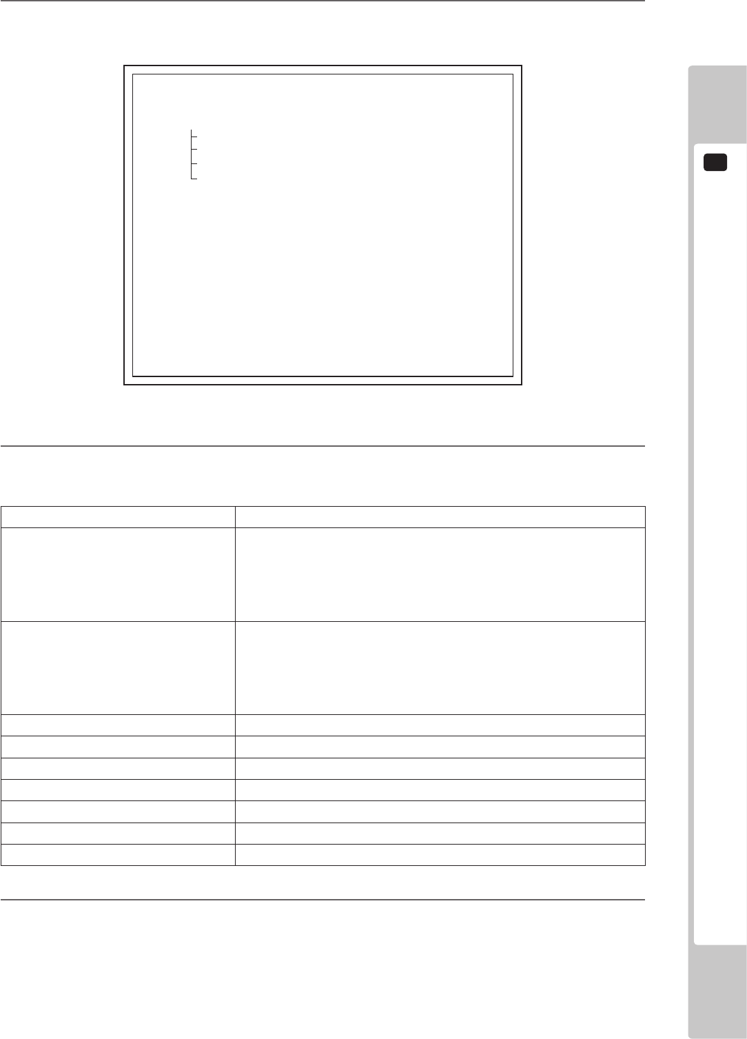
TEST MODE
2
59
3
Press the TEST Button on BOOKKEEPING 1/2 to move to BOOKKEEPING 2/2.
BOOKKEEPING 2/2
NUMBER OF GAMES *
START COUNT (WITH CARD) *
CONTINUE COUNT (WITH CARD) *
START COUNT (NO CARD) *
CONTINUE COUNT (NO CARD) *
SINGLE PLAY COUNT *
VERSUS PLAY COUNT *
TOTAL TIME **:**:**
PLAY TIME **:**:**
AVERAGE TIME **:**:**
PRESS TEST BUTTON TO EXIT
2-3-12 FIG. 02
4
Each item is explained below.
NUMBER OF GAMES Total number of games played.
START COUNT (WITH CARD) Total number of games started using an IC card.
Not displayed when CARD SYSTEM is OFF. (Displayed as START
COUNT with no differentiation between WITH CARD and NO
CARD.) See “2-3-4 GAME ASSIGNMENTS” for more information
about CARD SYSTEM settings.
CONTINUE COUNT
(WITH CARD)
Total number of games continued using a card.
Not displayed when CARD SYSTEM is turned off. (Displayed as
START COUNT with no differentiation between WITH CARD
and NO CARD.) See “2-3-4 GAME ASSIGNMENTS” for more
information about CARD SYSTEM settings.
START COUNT (NO CARD) Total number of games started without using a card.
CONTINUE COUNT (NO CARD) Total number of games continued without using a card.
SINGLE PLAY COUNT Number of times played in Single Player Mode.
VERSUS PLAY COUNT Number of times played in Versus Mode.
TOTAL TIME Amount of time the cabinet has been in operation.
PLAY TIME Amount of time game has been played.
AVERAGE TIME Average play time for one game.
5
Press the TEST Button to return to the GAME TEST MODE Screen.
2
TEST MODE
60
9-3-11 BACKUP DATA CLEAR
Delete all game records (game scores and GAME TEST MODE BOOKEEPING data).
1
On the GAME TEST MODE screen, select BACKUP DATA CLEAR and press the TEST Button. The
BACKUP DATA CLEAR screen appears.
BACKUP DATA CLEAR
YES (CLEAR)
-
> NO (CANCEL)
SELECT WITH SERVICE BUTTON AND PRESS TEST BUTTON
BACKUP DATA CLEAR
COMPLETED
PRESS TEST BUTTON TO EXIT
2-3-13 FIG. 01
2
Select item to either clear data or to cancel the function, and then conrm with the TEST Button.
YES (CLEAR) All game records are cleared. After clearing, “COMPLETED” is displayed.
NO (CANCEL) All game records are not cleared.
3
When YES (CLEAR) has been selected and the TEST Button pressed, all data is cleared. Then
“COMPLETED” is displayed and press the TEST Button to return to the GAME TEST MODE screen.
Move the cursor to NO (CANCEL) and press the TEST Button to return to the GAME TEST MODE screen
without clearing the data.
2-3-13 FIG. 02
TEST MODE
2
61
9-3-12 DEFAULT SETTING
The DEFAULT SETTING option for each item allows you to restore all values and settings to their default.
1
For example, select DEFAULT SETTING on the GAME ASSIGNMENTS screen and press the TEST
Button to display the DEFAULT SETTING screen.
GAME ASSIGNMENTS DEFAULT SETTING
YES (DEFAULT SETTING)
-
> NO (CANCEL)
SELECT WITH SERVICE BUTTON AND PRESS TEST BUTTON
2-3-14 FIG. 01
2
Each item is explained below.
YES (DEFAULT SETTING) Restore all game settings to their default.
NO (CANCEL) Do not restore all game setting to their default.
3
Select YES (DEFAULT SETTING) and press the TEST Button to restore all settings to their default, and
select NO (CANCEL) and press the TEST Button to return to the GAME ASSIGNMENTS screen.
10
CONTROL PANEL (HANDLE MECHA)
62
CONTROL PANEL (HANDLE MECHA)
10
• ExerciseextremecautionwhenhandlingtheinternalpartsoftheControlPanel.
Watchoutfordamage,warpingandloss.Thelossofjustonepiecemayresultin
damagetoorleadtofaultyoperationoftheentireunit.
• Becarefulthatyourngersdonotgetcaughtwhenopeningandclosingthe
controlpanel,adjustingtheVRbracket,orperformingothermaintenancetasks.
• Whensecuringtheplastic-madeparts,donotexcessivelyfastenscrewsand
nuts.Failuretoobservethismaydamagethepartsandcauseinjurydueto
fragmentsresultingfromdamage.
• Donottouchthesteeringwheelwhenswitchingontheunit.Thesteeringwheel
undergoesautomaticinitializationaftertheunitisswitchedon.
• Inordertopreventanelectricshockandshortcircuit,besuretoturnpoweroff
beforeperformingworkbytouchingtheinteriorpartsoftheproduct.
• Becarefulnottodamagethewires.Damagedwiresmaycauseelectricshock
orshortcircuitorpresentarerisk.
• Donottouchundesignatedplaces.Touchingplacesnotdesignatedcancause
electricshockorshortcircuit.
• Thisworkshouldbeperformedbythesitemaintenanceindividualorother
skilledprofessional.Performingworkbynon-technicalpersonnelcancause
electricshockhazard.
• DonotperformworkotherthanthosespeciedinthisManualinorderto
preventaccidentsduringperformingworkandoperationafterperformingwork.
PerformingworknotspeciedinthisManualmayrequirespecialtrainingforthis
product.Ifperformingworkotherthanthosestatedinthismanualisrequiredfor
repair,contacttheofceshereinstatedinthismanualorwhereyoupurchased
theproductfromandaskforrepairorinquirehowtorepair.
• Beverycarefulwhensoldering.Handlingasolderingironcarelesslymayresult
inareoraburn.
• Beextremelycarefulwhenheatingtheheat-shrinkabletube.Failuretodoso
mayresultinareorburns.
• Immediatelyafterthegameisnished,themotormaystillbeveryhot.
Whenperformingtheremovalwork,waituntilthemotorcoolsoff.
• Thisunitisaheavyitemweighingapproximately20kg(44.1lb).Therefore,be
verycarefulwhenperformingthework.Usepluralworkers.
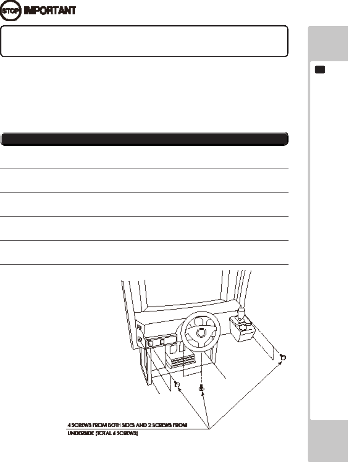
CONTROL PANEL (HANDLE MECHA)
10
63
10-1 REMOVING THE CONTROL PANEL
Besuretoperformvolume'smovevaluesettingintheINPUTASSIGNMENTSinthe
GameTestModeafterreplacingoradjustingtheVolume.
In cases the Steering operability is poor and the adjustment of VOLUME SETTING in the TEST mode has no effect,
the causes may be the volume gear's mesh failure and or volume malfunctioning.
Adjust volume gear mesh or replace the volume as per the following procedure.
In this product, when the steering wheel is moved fully left/right, if the volume shaft is rotating within the movable
range, the volume is not feared to be damaged.
Secure the volume in the manner the volume shaft is oriented as shown and the gears are appropriately engaged
when the steering wheel is in the centering position allowing the car to go straight forward.
A 5 mm hexagonal wrench is required for the following procedure.
1
Turn off the power.
2
Remove 4 screws from both sides of the Control Panel’s front part.
3
Remove 2 screws from underside of the Control Panel.
4
Wiring connectors are connected inside the Control Panel. Be careful not to damage any of the wiring, and
carefully pull out the Control Panel.
5
Unplug the wiring connectors.
10-1 FIG. 01
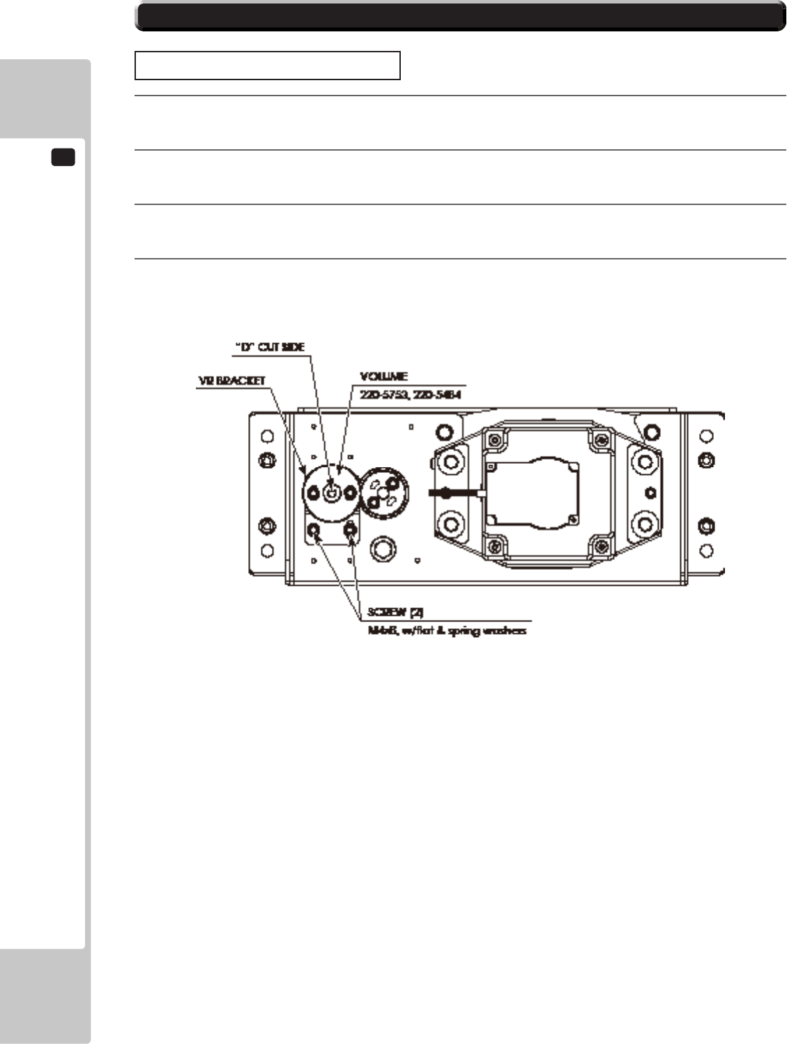
10
CONTROL PANEL (HANDLE MECHA)
64
10-2 ADJUSTING/REPLACING THE VOLUME
ADJUSTMENT PROCEDURE
1
Loosen the 2 screws that secure the VR Bracket and move the VR Bracket to adjust the angle and condition
of the gear alignment.
2
Keeping the handle straight, align the gears so that the direction of the D Cut side of the V.R. Shaft matches
that shown in the diagram.
3
Tighten the 2 screws and secure the VR Bracket.
4
Check to make sure the value on the Input Test screen is within the range 80H ± 8H when the steering unit
is in the straight position.
10-2 FIG. 01
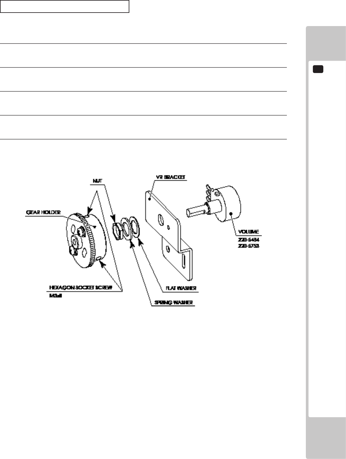
CONTROL PANEL (HANDLE MECHA)
10
65
REPLACEMENT PROCEDURE
This procedure requires the following tools: Phillips screwdriver for the M4 screws, 1.5 mm hexagonal wrench,
11-12 mm monkey wrench, nipper, cutter, wire stripper, soldering iron, industrial dryer and heat-shrinkable tube.
1
Remove the connectors.
2
Remove the 2 screws securing the VR Bracket and remove the entire Bracket and V.R.
3
Loosen the 2 hexagon socket screws on the Gear Holder and remove the Gear Holder.
4
Remove the nut securing the VR Bracket, then separate the Volume from the VR Bracket and replace it.
5
Check to make sure the value on the Input Test screen is within the range 80H ± 8H when the steering unit
is in the straight position.
10-2 FIG. 02
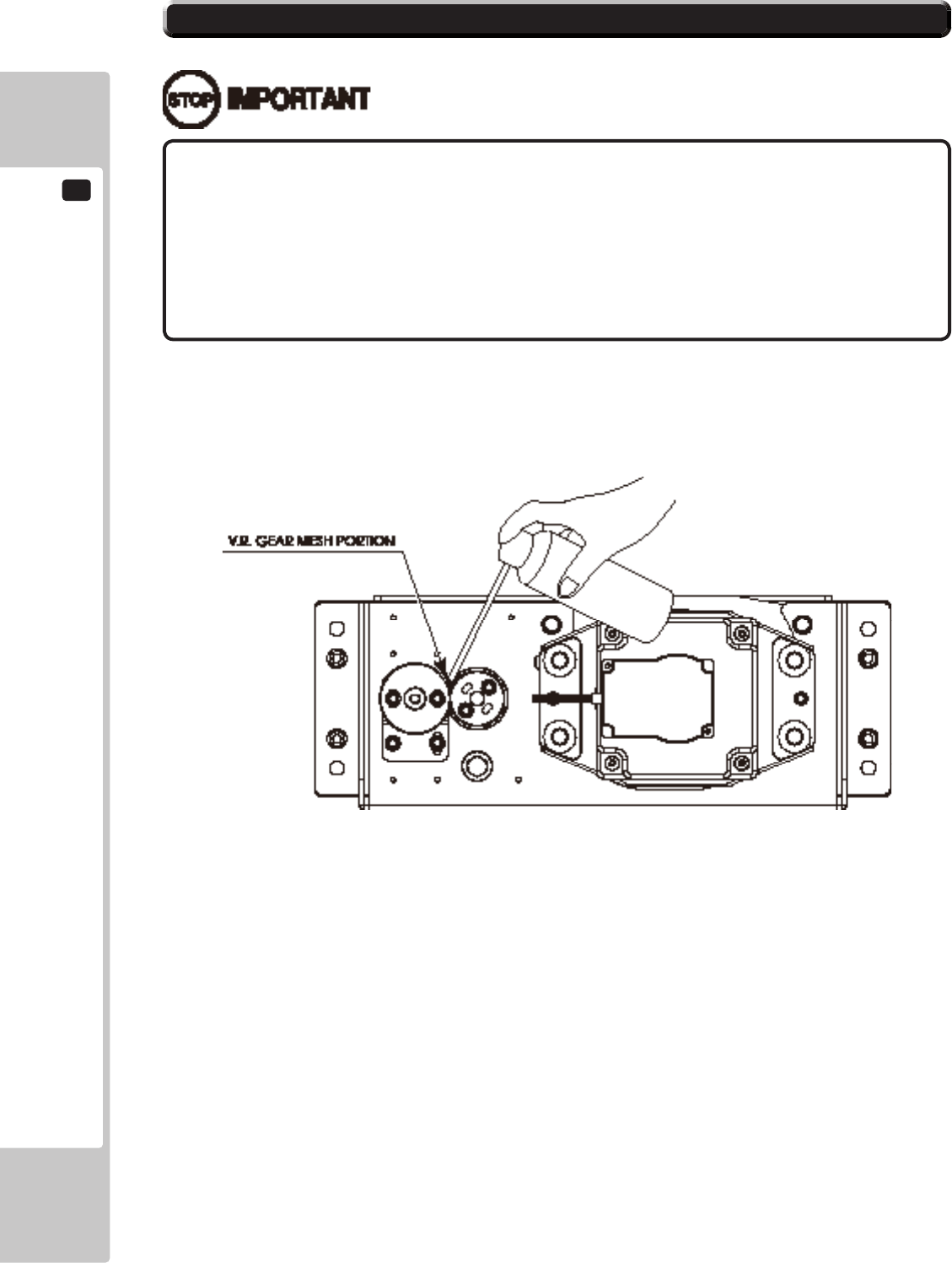
10
CONTROL PANEL (HANDLE MECHA)
66
• Besuretousethedesignatedgrease.Usingundesignatedgreasecancause
partsdamage.
• Donotapplygreasetolocationsotherthanasspecied.Doingsomaycreate
ariskofoperationalproblemsanddeteriorationofparts.
• Thedesignatedperiodsforgreasingserveonlyasaguide.Wheneverthereare
squeaksorotheranomalies,applygreaseatdesignatedlocations.
10-3 GREASING
Use spray grease once every three months to grease up the gear mesh portion of the constituent parts.
Use "Grease Mate" (part number 090-0066) for the spray grease.
10-3 FIG. 01
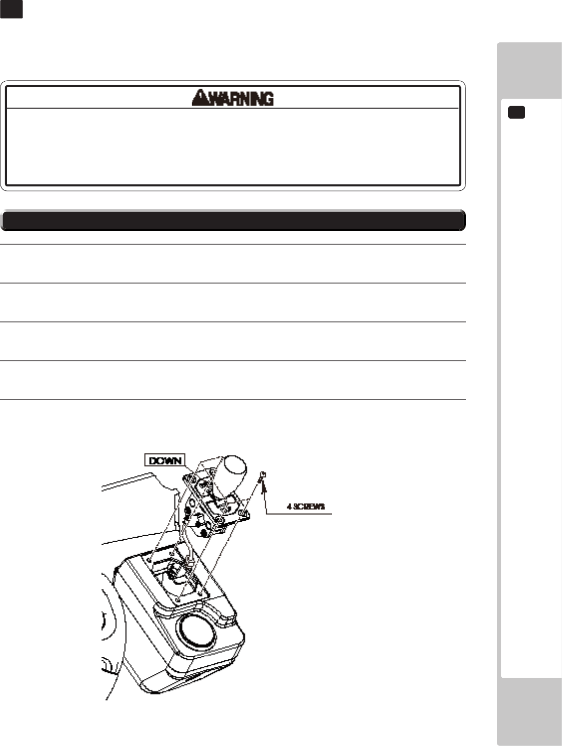
SHIFT LEVER
11
67
SHIFT LEVER
11
11-1 REMOVING THE SHIFT LEVER
• Whenworkingwiththeproduct,besuretoturnthepoweroff.Workingwiththe
poweronmaycauseanelectricshockorshortcircuit.
• Becarefulnottodamagethewires.Damagedwiresmaycauseanelectric
shock,shortcircuitorpresentariskofre.
In the Test Mode, if the SHIFT LEVER's SW can not be inputted satisfactorily, replace the Switch.
When performing the work, remove the Shift Lever Unit.
1
Turn the power off.
2
Remove 4 screws to lift the Shift Lever Unit.
3
Disconnect the connector to remove the Shift Lever Unit.
4
When reinstalling, follow the procedure opposite as when removing. At this time, ensure that "DOWN"
display appears on the upper part as shown.
5
After reinstalling, be sure to check INPUT TEST in the Game Test mode.
11-1 FIG. 01
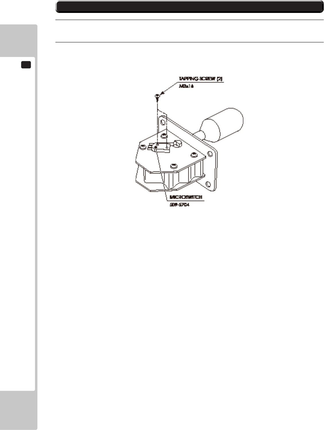
11
SHIFT LEVER
68
11-2 SWITCH REPLACEMENT
1
Disconnect the wiring connector of the switch to be replaced.
2
Remove the 2 tapping screws to replace the Microswitch.
11-2 FIG. 01
ACCELERATOR & BRAKE
12
69
Besuretoperformvolume'smovevaluesettingintheINPUTASSIGNMENTSinthe
GameTestModeafterreplacingoradjustingtheVolume.
ACCELERATOR & BRAKE
12
Donottouchthesteeringwheelwhenswitchingontheunit.Thesteeringwheel
undergoesautomaticinitializationaftertheunitisswitchedon.
• Alwaysdisengagethepowerbeforebeginningwork.Otherwisetherecould
beanelectricshockorshortcircuit.NotethatwhenusingTESTmodetherewill
beelectricityrunningthroughthemachine.Donottouchanypartsthatarenot
speciedinthesedirections.
• Becarefulnottodamagethewires.Damagedwiresmaycauseelectricshock
orshortcircuitorpresentariskofre.
• Donottouchundesignatedplaces.Touchingplacesnotdesignatedcancause
electricshockorshortcircuit.
• Thisworkshouldbeperformedbysitemaintenancepersonnelorotherskilled
professionals.Workperformedbynon-technicalpersonnelcancauseasevere
accidentsuchasanelectricshock.
• Topreventaccidentswhileworkingorwhileoperatingtheproductafterithas
beeninstalled,besurenottoconductanyproceduresotherthanthosegivenin
thismanual.Ifaprocedurenotgiveninthismanualisrequired,requestservice
fromtheofcegiveninthismanualorfromthepointofpurchase.
When the accelerator and brake pedal do not operate properly, either the volume attachment position must be
adjusted, or the volume must be replaced. Also, the gear alignment position and spring should be greased once every
three months.
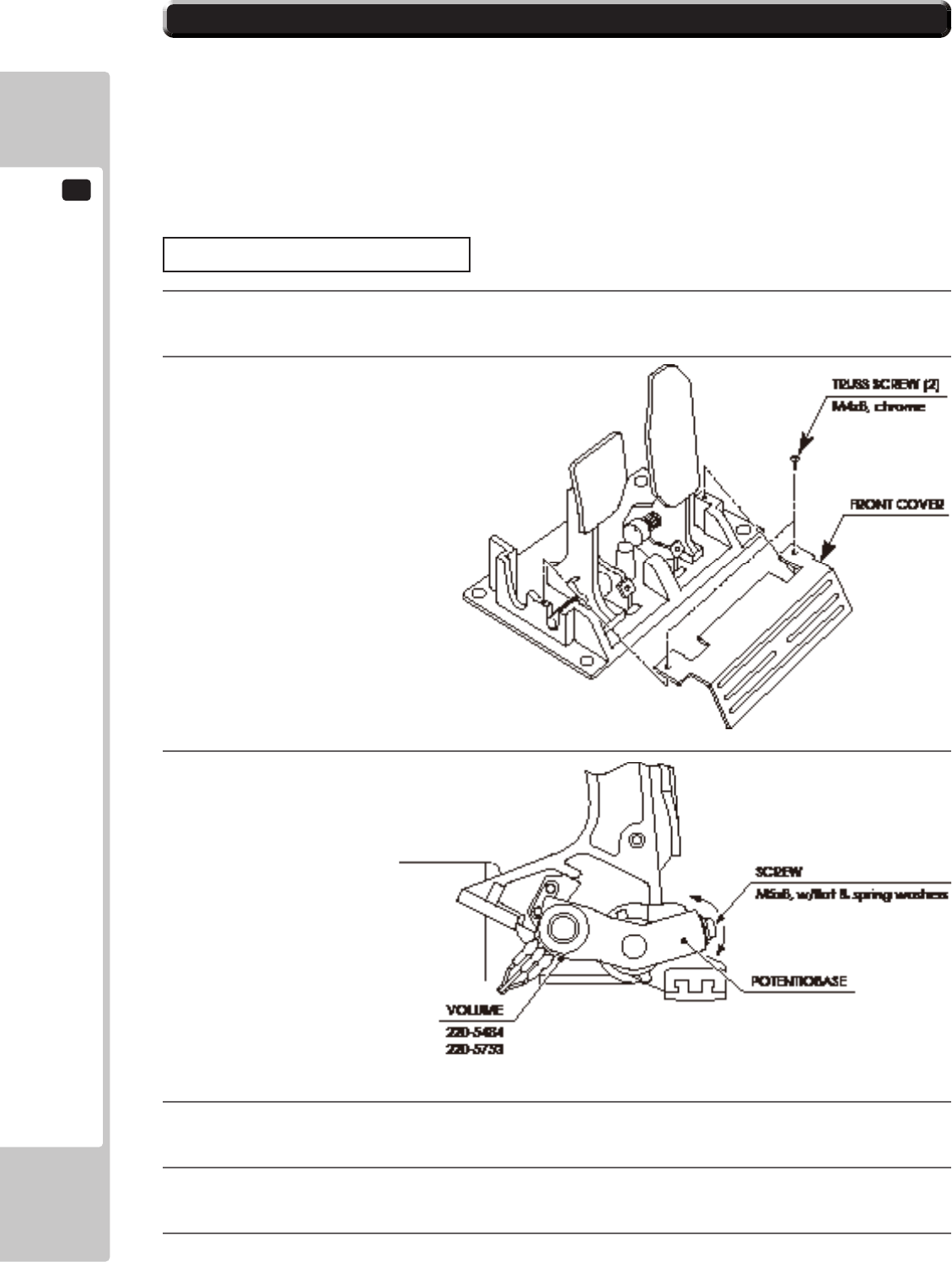
12
ACCELERATOR & BRAKE
70
12-1 VOLUME ADJUSTMENT AND REPLACEMENT
The appropriate value for acceleration volume is under 30H when released and over C0H when stepped on.
The appropriate value for brake volume is under 30H when released and over C0H when stepped on.
Check Volume values in the TEST mode.
Since work is performed inside the energized cabinet, be very careful so as not to touch undesignated places.
Touching places not specied can cause electric shock or short circuit.
The following tools are required for the operations below: Phillips screwdrivers for M4 and M5, hexagon wrench
with measuring distance of 1.5 mm, and thread sealant.
ADJUSTING PROCEDURE
1
Turn off the power.
2
Remove two truss screws, and remove the front cover of
the accelerator and brake.
3
Loosen the screw that secures the potentiobase,
and adjust the volume values by moving the base.
4
Fasten the potentiobase.
5
On the INPUT ASSIGNMENTS Screen in the Game Test Mode, set the volume values.
6
Conrm that the values change smoothly by operating the pedal.
12-1 FIG. 01
12-1 FIG. 02
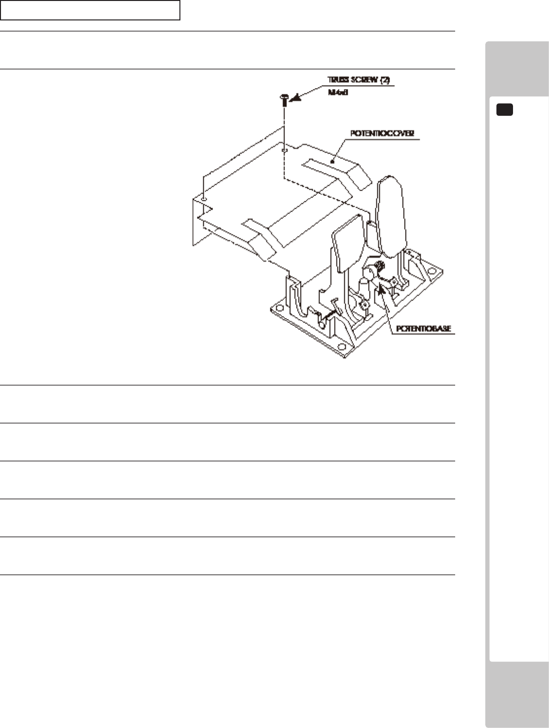
ACCELERATOR & BRAKE
12
71
REPLACING THE VOLUME
1
Turn off the power.
2
Remove two screws, and remove the potentiocover.
3
Undo the connector of the volume to be replaced.
4
Remove the screw that fastens the potentiobase.
5
With the volume still attached, remove the potentiobase.
6
Remove the base and the gears, and replace the volume. When attaching the volume, use the thread locker.
7
After replacement, set the volume as described in the “Adjusting Procedure” section above.
8
After adjusting the setting, conrm that the values change smoothly by operating the pedal.
12-1 FIG. 03
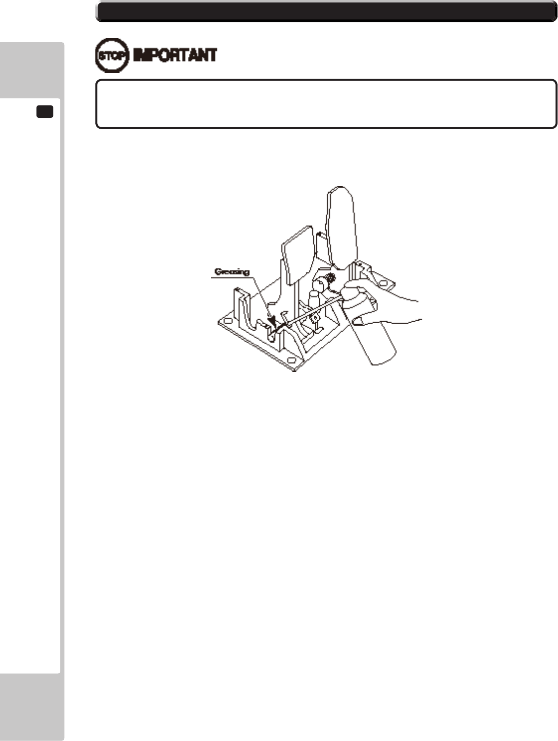
12
ACCELERATOR & BRAKE
72
Besuretousethedesignatedgrease.Usingundesignatedgreasecancauseparts
damage.
12-2 GREASING
Grease the spring and gear alignment area once every three months.
Use GREASE MATE (PART No. 090-0066) as spray grease.
12-2 FIG. 01
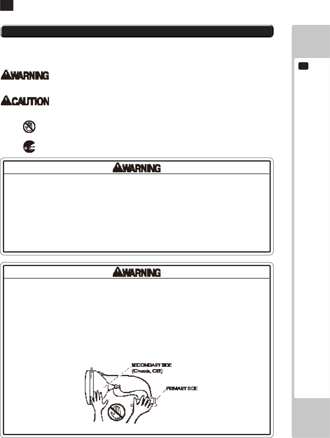
MONITOR
13
73
MONITOR
13
13-1
CAUTIONS AND WARNINGS CONCERNING THE SAFETY FOR HANDLING THE MONITORS
• Whenperformingsuchworkasinstallingandremovingthemonitor,inserting
anddisconnectingtheexternalconnectorstoandfrommonitorinteriorandthe
monitor,besuretodisconnectthepowerconnector(plug)beforestartingthe
work.Proceedingtheworkwithoutfollowingthisinstructioncancauseelectric
shockormalfunctioning.
• Usingthemonitorbyconvertingitwithoutobtainingapriorpermissionisnot
allowed.SEGAshallnotbeliableforanymalfunctioningandaccidentcaused
bysaidconversion.
• PrimarysideandSecondaryside
Themonitor'scircuitwhichisdividedintothePrimarysideandSecondaryside,
iselectricallyisolated.Donottouchtheprimaryside,ordonottouchboththe
primarysideandthesecondarysidesimultaneously.Failingtoobservethe
instructioncancauseelectricshockandthisisverydangerous.Whenmaking
monitoradjustments,useanonconductivedriverandmakeadjustmentwithout
touchinganypartotherthantheAdjustmentV.R.andknob.Also,besurenotto
causeashort-circuittothePrimarysideandSecondaryside.Ifshort-circuited,it
cancauseelectricshockormalfunctioning,whichisverydangerous.
Before handling the monitors, be sure to read the following explanations and comply with the caution/warning
instructions given below. Note that the caution/warning symbol marks and letters are used in the instructions.
Indicates that handling the monitors erroneously by disregarding this warning may cause a
potentially hazardous situation, which could result in death or serious injury.
Indicates that handling the monitors by disregarding this caution may cause a potentially
hazardous situation, which could result in personal injury and or material damage.
Indicates that access to a specic part of the equipment is forbidden.
Indicates the instruction to disconnect a power connector or to unplug.
14-1 FIG. 01
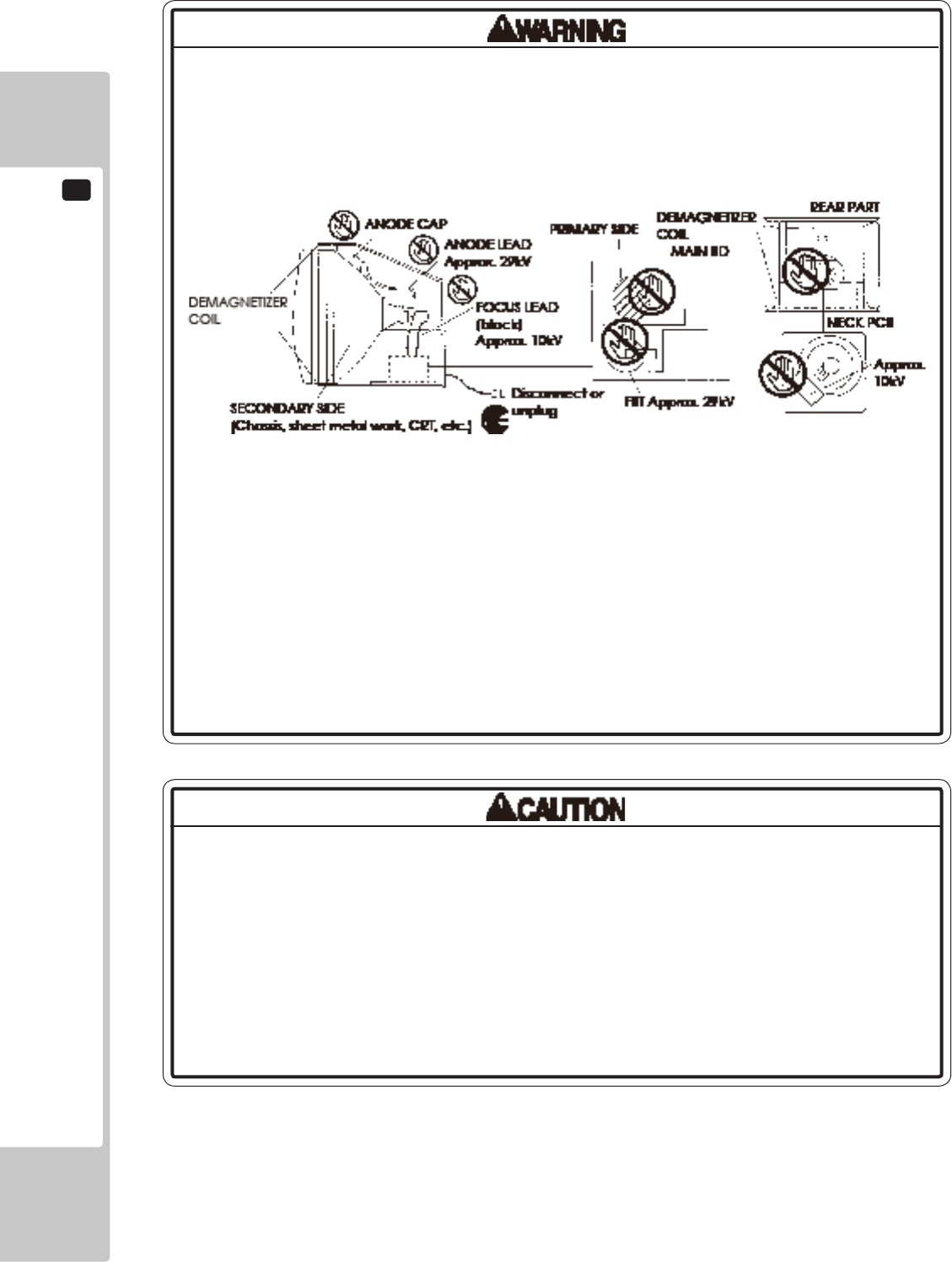
13
MONITOR
74
• StaticElectricity
TouchingtheCRTsurfacesometimescausesyoutoslightlyfeelelectricity.Thisis
becausetheCRTsurfacesaresubjecttostaticandwillnotadverselyaffectthe
humanbody.
• Installationandremoval
EnsurethattheDemagnetizerCoil,FBT(Fly-BackTransformer),AnodeLeadand
FocusLeadarenotpositionedclosetothesheetmetalwork'ssharpedges,etc.
andavoiddamagingtheinsulatedportionssoasnottocauseelectricshock
andmalfunctioning.(Forthenameofparts,refertotheaboveFigures).
• High-tensionVoltage
Someofthepartsinsidemonitoraresubjecttohigh-tensionvoltageinexcess
of20,000voltsandverydangerous.Therefore,donottouchthemonitorinterior.
Shouldsoldering&paperwastes,etc.bemixedinthemonitorinterior,turnthe
poweroffsoasnottocausemalfunctioningorrehazard.
• ConnectingtheCRTandPCB
ForcombiningtheCRTandPCB,usethespeciedpartNo.tomaintainthe
statusofadjustmentsmadeatthefactory.TheanodeoftheCRTitselfwillbe
accumulativelychargedastimeelapses,generatinghigh-tensionvoltage
whichisverydangerous.ThemonitorshouldbeusedwiththeChassis,CRTand
PCBassembled.Whenrepair,etc.isrequiredatthetimeofmalfunctioning,
besuretosenditinan"asisassembled"condition.Ifthesearedisassembled,
what'schargedtosaidhightensionvoltagecanbedischarged,causing
averyhazardoussituation.Therefore,undernocircumstancesshoulditbe
disassembled.
14-1 FIG. 02
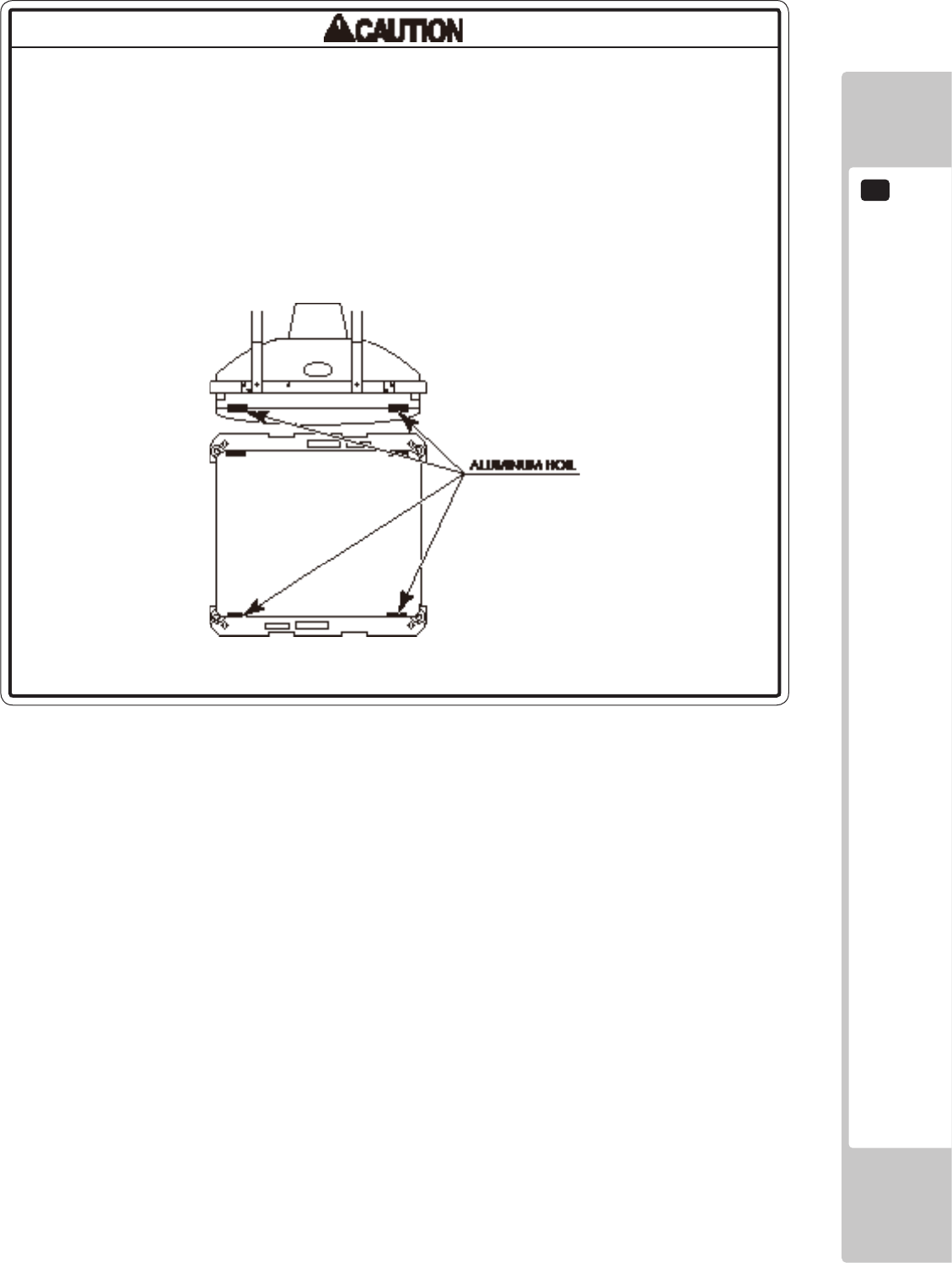
MONITOR
13
75
Forthepurposeofstaticprevention,specialcoatingisappliedtotheCRTface
ofthisproduct.Toprotectthecoating,payattentiontothefollowingpoints.
Damagingthecoatinglmcancauseelectricshocktothecustomers.
• Donotapplyorrubwithaharditem(arodwithpointededge,pen,etc.)toor
ontheCRTsurfaces.
• Avoidapplyingstickers,seals,etc.ontheCRTface.
• DonotremovealuminumfoilsfromtheCRTcorners.Removingthealuminum
foilscancausestaticpreventioneffectstobelowered.
14-1 FIG. 03
13
MONITOR
76
13-2 CLEANING THE CRT SURFACES
StaticpreventivecoatingisappliedtotheCRTsurfaces.Whencleaning,pay
attentiontothefollowingpoints.Peelingoffofstaticpreventivecoatcancause
electricshock.
• Removesmearsbyusingadry,softcloth(annels,etc.).Donotuseacoarse
gauze,etc.
• Forsmearremovingsolvent,alcohol(ethanol)isrecommended.Whenusing
chemicaldetergent,besuretofollowinstructionsbelow:
-Dilutechemicaldetergentwithwateranddipasoftclothinandthenthoroughly
wringittowipesmearsoff.
-Donotuseachemicaldetergentcontaininganabradant,powderorbleaching
agent.
-Donotusealkalinechemicaldetergentssuchas"glasscleaner"availableon
themarketorsolventssuchasthinner,etc.
• DonotruborscratchtheCRTfacewithharditemssuchasbrushes,scrubbrush,
etc.
Clean the CRT surfaces once a week. When cleaning, pay attention to the above caution so that the antistatic coating
will not come off.
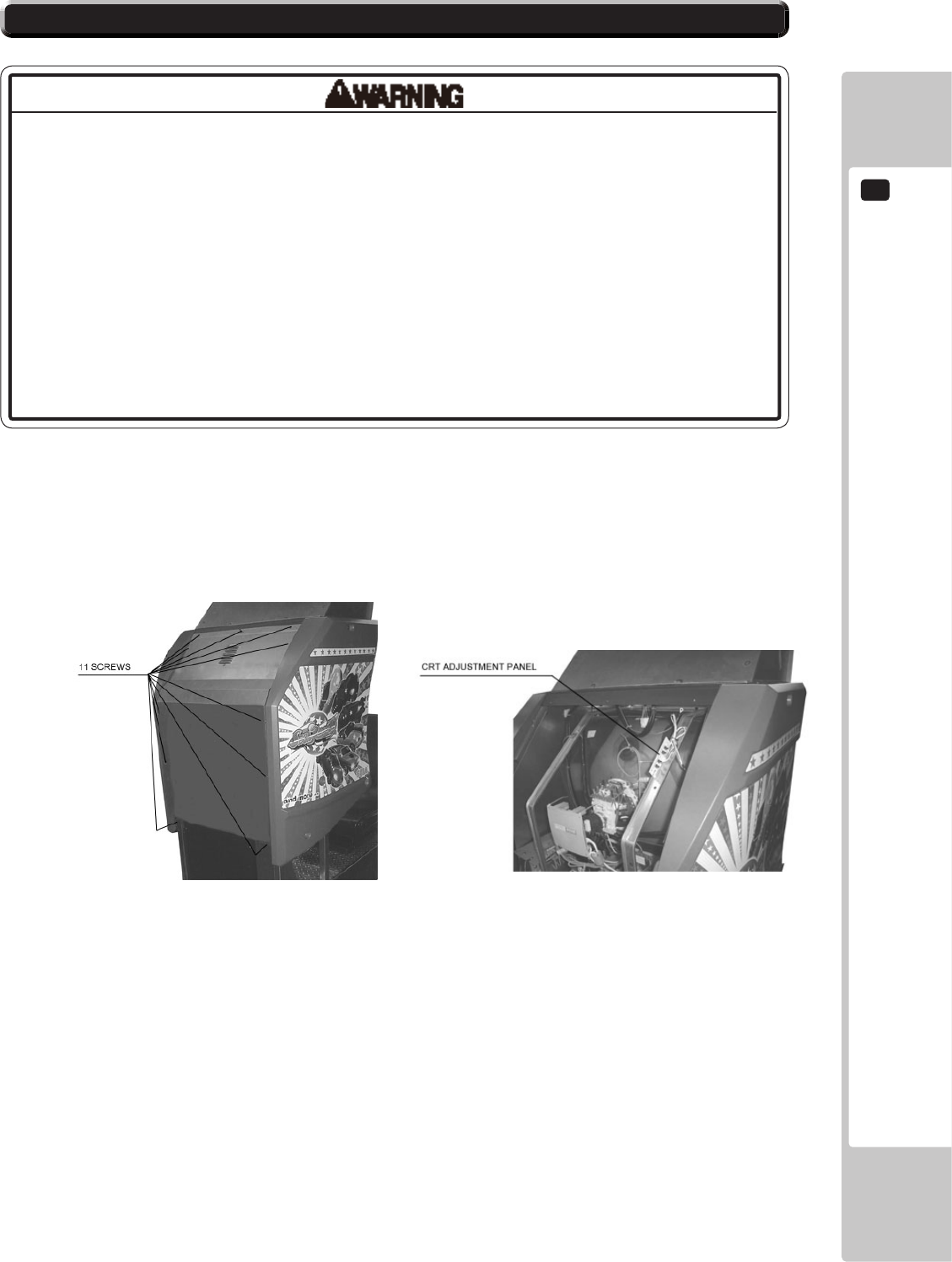
MONITOR
13
77
13-3 ADJUSTMENT PROCEDURE
• Monitoradjustmentshavebeenmadeatthetimeofshipment.Therefore,do
notmakefurtheradjustmentwithoutajustiablereason.Adjustingthemonitor
whichcontainshightensionpartsisdangerouswork.Also,anerroneous
adjustmentcancausedeviatedsynchronizationandimagefault,resultingin
malfunctioning.
• Besuretoperformappropriateadjustmentofthemonitor(projector).For
operationofthismachine,donotleavemonitor'sickeringordeviationas
is.Failuretoobservethiscancausetoworsentheplayers'orthecustomers'
physicalconditions.
• Donottouchundesignatedplaces.Touchingplacesnotdesignatedcancause
electricshockorshortcircuit.
To make monitor adjustment, take off back cover removing 11 screws.
The adjustment board appears when the back cover is open.

13
MONITOR
78
This product’s monitor is SANWA 29PFX (Sega part#: 99-60-718). For adjustment method, carefully read and
carry out the following. With this product, the hue of each color cannot be adjusted.
There are 4 buttons to operate the adjustment.
Pressing FUNCTION button displays the menu screen.
- When pressing the DEGAUSS button, degaussing is performed.
Once degaussed, it takes 30 minutes or longer to have degaussing function agai.
CONT : adjusts image contrast.
With the UP button, it becomes deep and becomes light with the DOWN button.
BRIT : adjusts the on-screen image brightness.
With the UP button, it becomes bright and becomes dark with the DOWN button.
HSIZ : adjusts the horizontal image size.
With the UP button, it becomes large and becomes small with the DOWN button.
HPOS : adjusts the horizontal image's position.
With the UP button, it moves to the left and moves to the right with the DOWN button.
VSIZ : adjusts the vertical image size.
With the UP button, it becomes large and becomes small with the DOWN button.
VPOS : adjusts the vertical image's position.
With the UP button, it moves upwards and moves downwards with the DOWN button.
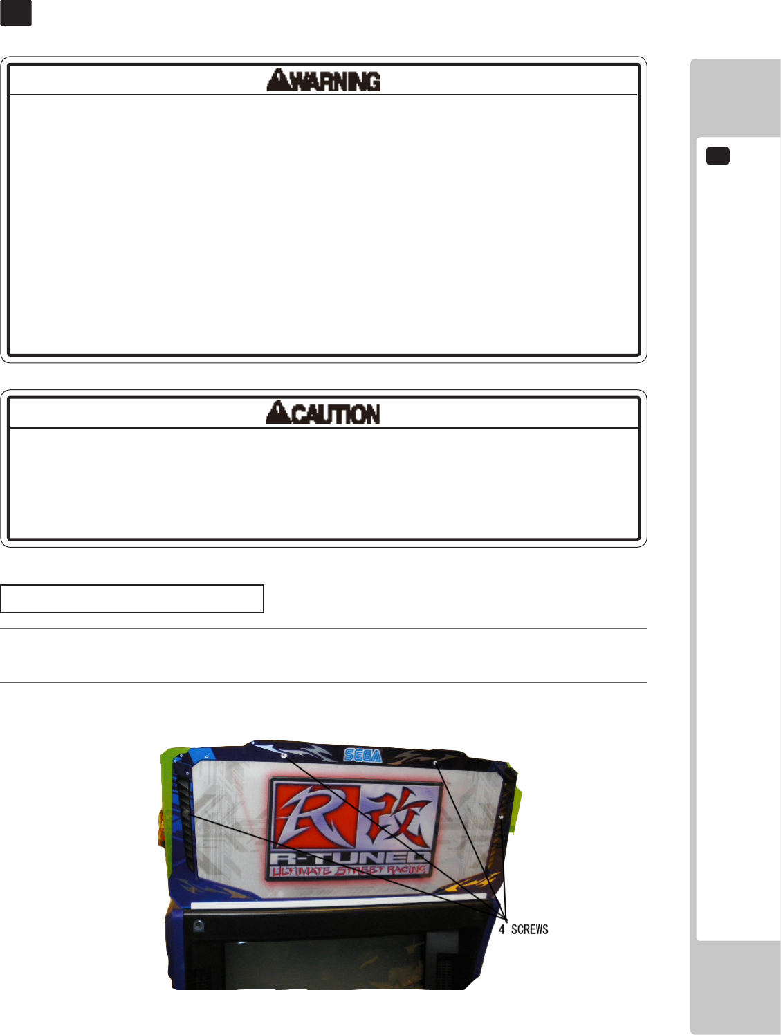
FLUORESCENT LIGHT/OTHER LAMPS REPLACEMENT
14
79
FLUORESCENT LIGHT/OTHER LAMPS REPLACEMENT
14
• Becarefulwhenhandlingtheplasticparts.Failuretoobservethismaycause
injuryordamageduetofragments,etc.
• Donotattempttoreplacebillboarduorescentlampswhilestandingonthe
base.Ifyoushouldmisstepwhileworking,youcouldstumbleorfalldown.
• Whenworkingwiththeproduct,besuretoturnthepoweroff.Workingwiththe
poweronmaycauseanelectricshockorshortcircuit.
• Youmaygetburnedbyahotuorescentlamporotherlamps.Payfullattention
tothelampswhenperformingthework.
• Besuretouselampsofthedesignatedrating.Usinglampsofundesignated
ratingcancauseareormalfunctioning.
• Thereisthedangerofshortcircuitsorsmokegenerationduetodeterioration
ofinsulationinlightingxturesresultingfromagedeterioration.Checkfor
anomaliessuchasthefollowing:Doesitsmelllikesomethingisburning?Isthere
socketdiscoloration?Areanylampsbeingreplacedfrequently?Dolampsnot
goonproperly?
Billboard Fluorescent Light
1
Turn off the power.
2
Remove the 4 screws then remove the front billboard plate.
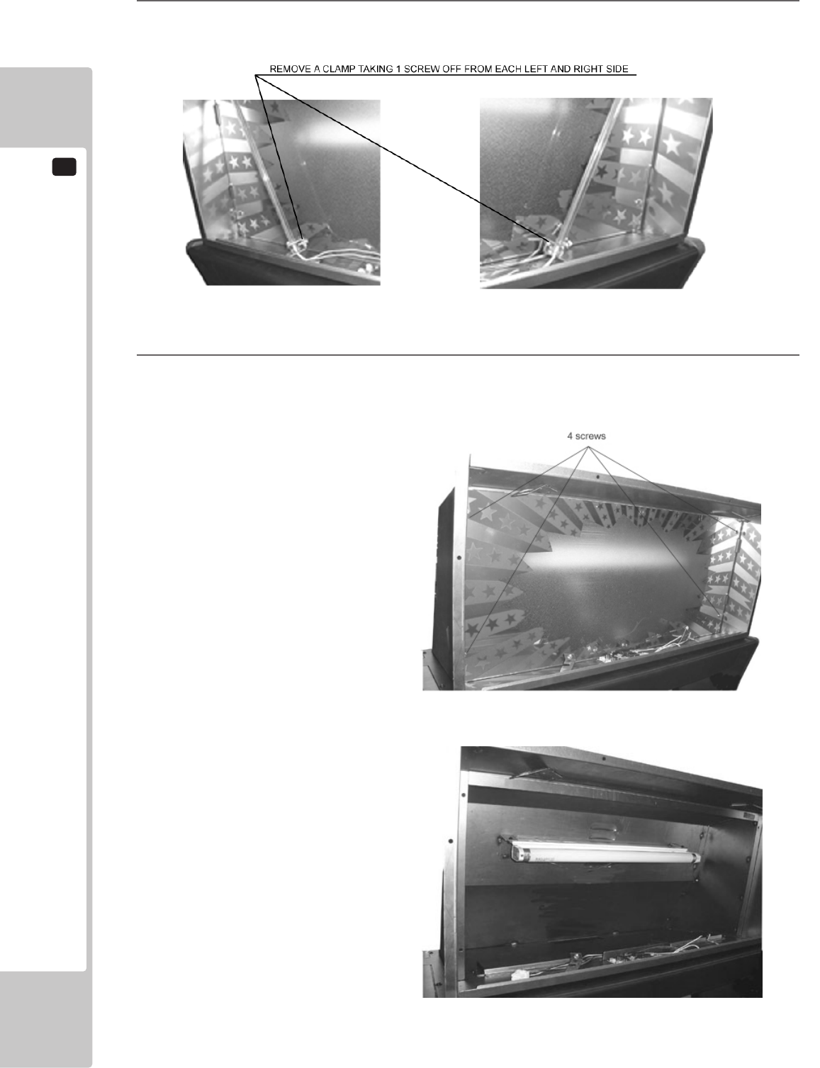
14
FLUORESCENT LIGHT/OTHER LAMPS REPLACEMENT
80
3
Remove a clamp taking a screw out and remove a red CCFL from each left and right side.
4
Remove the back marquee plate and replace the uorescent light and glow lamp.
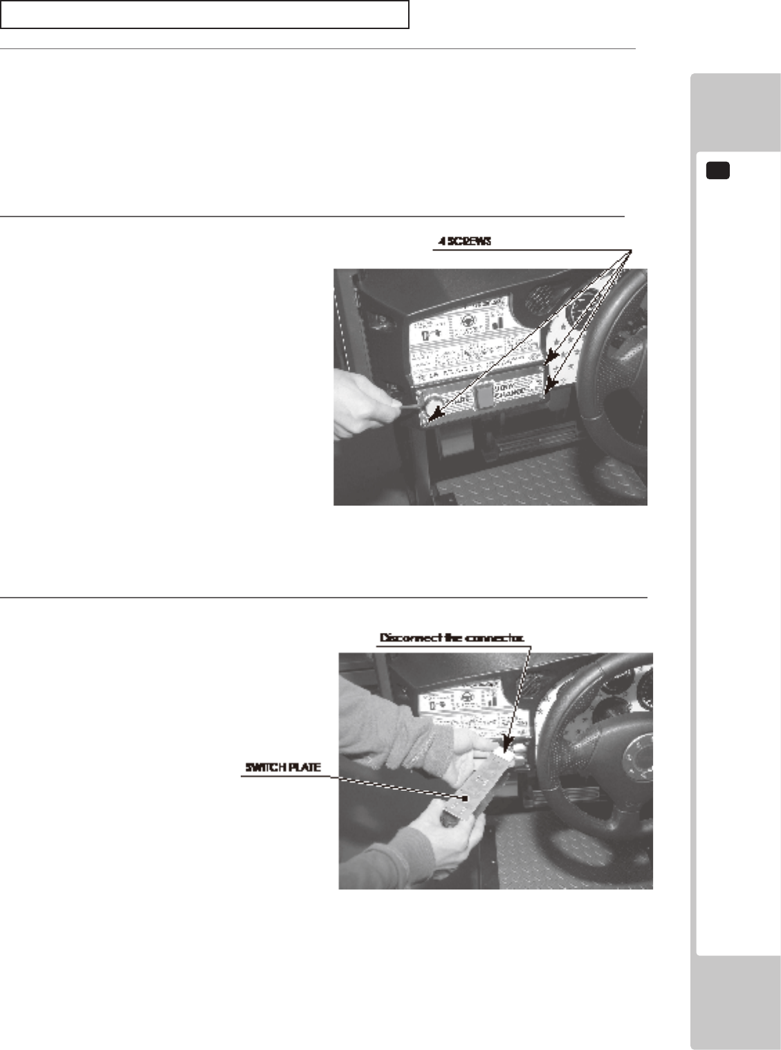
FLUORESCENT LIGHT/OTHER LAMPS REPLACEMENT
14
81
3
Remove the Switch Plate. The Switch Plate contains wiring connections. Disconnect the connector, taking
care not to damage the wiring.
2
Remove 4 screws.
Start Button Lamp, View Change Button Lamp
1
Turn off the power.
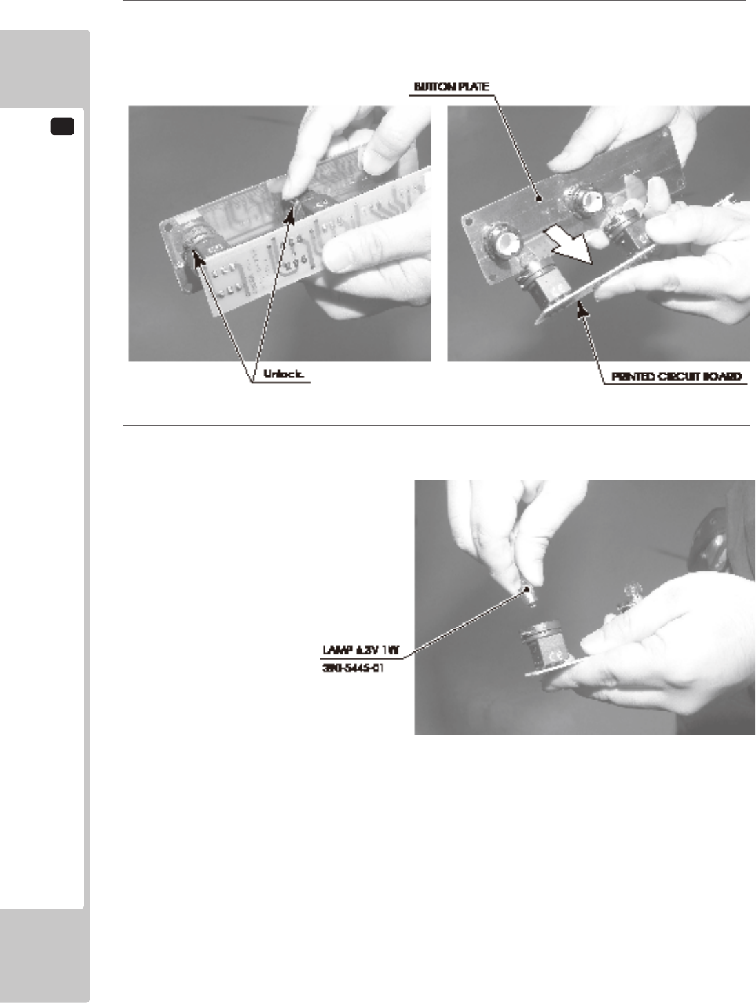
14
FLUORESCENT LIGHT/OTHER LAMPS REPLACEMENT
82
5
Press and turn the lamp counter-clockwise to remove it.
4
There is a metal tting at the base of the buttons on the Button Plate. Rotate this metal tting to unlock it,
then remove the printed circuit board from the Button Plate.
PERIODIC INSPECTION
15
83
PERIODIC INSPECTION
15
• Onceayear,checktoseeifpowercordsaredamaged,theplugissecurely
inserted,dustisaccumulatedbetweenthesocketoutletandthepowerplug,
etc.Usingtheproductwithaccumulateddustintheinteriormaycausereor
electricshock.
• Neveruseawaterjet,etc.tocleantheinsideandoutsideofthecabinet.If
wetnessoccursforanyreason,donotusetheproductuntilithascompletely
dried.
• Onceayear,requesttheofceshownonthismanualorthedealerfromwhom
theproductwasoriginallypurchasedtoperformtheinternalcleaning.Usingthe
productwithaccumulateddustintheinteriormaycausereorotheraccidents.
Notethatyouareliableforthecostofcleaningtheinteriorparts.
• Thereisthedangerofaccidentsinvolvingelectricalshortscircuitsorrecaused
byfactorssuchasthedeteriorationofinsulationinelectricalandelectronic
equipmentovertime.Checkthattherearenoabnormalitiessuchasodorsfrom
burning.
The items listed below require periodic check and maintenance to retain the performance of this machine and to
ensure safe business operation.
When handling the controller, the player will be in direct contact with it. In order to always allow the player to enjoy
the game, be sure to clean it regularly. Also, it is advisable to provide wet tissue, etc. available for player use.
16 TABLE 01 PERIODIC INSPECTION TABLE
ITEMS DESCRIPTION PERIOD
CABINET Conrm that adjusters contact oor Daily
CONTROL PANEL Volume inspection Monthly
Gear alignment inspection Every 3 months
Greasing Every 3 months
SHIFT LEVER Switch inspection Monthly
Greasing Every 3 months
ACCELERATOR & BRAKE Volume inspection Monthly
Gear and spring potion greasing Every 3 months
MONITOR Screen cleaning Weekly
Conrm settings Monthly or when
moving
COIN CHUTE DOOR Coin switch inspection Monthly
Coin insertion test Monthly
Selector cleaning Every 3 months
SEAT Greasing to the seat rail Every 3 months
GAME BD Memory Test Monthly
Conrm settings Monthly
POWER CABLES Inspection, Cleaning 1 year
INTERIOR Cleaning 1 year
CABINET SURFACES Cleaning As appropriate

15
PERIODIC INSPECTION
84
Cleaning the Cabinet Surfaces
When the cabinet surfaces are badly soiled, remove stains with a soft cloth dipped in water or diluted (with water)
chemical detergent and squeezed dry. To avoid damaging surface nish, do not use such solvents as thinner, benzine,
etc. other than ethyl alcohol, or abrasives, bleaching agent and chemical dustcloth.
Some general-purpose household, kitchen and furniture cleaning products may contain strong solvents that degrade
plastic components, coatings, and print. Before using any cleaning product, read the product's cautionary notes
carefully and test the product rst on a small area that is not highly visible.
Seat (Greasing to Seat Rail Portion)
Move the Seat to the rearmost position and apply spray greasing to the portion shown at the right once every 3
months by using NOK KLUBER L60 or GREASE MATE SEGA PART No. 090-0066.
After greasing, move the Seat a few times forward and backward so as to allow the grease to be applied all over
uniformly.
Be sure to wipe grease which attaches to the surfaces of the PROTECT RUBBER on the Seat Rail, or any excess
grease.
TROUBLE SHOOTING
16
85
TROUBLESHOOTING
16
16-1
TROUBLESHOOTING (WHEN NO ERROR MESSAGE IS SHOWN)
• Inordertopreventelectricshockandshortcircuit,besuretoturnpoweroff
beforeperformingwork.
• Becarefulsoasnottodamagewirings.Damagedwiringcancauseelectric
shockorshortcircuit.
• AfterremovingthecauseofthefunctioningoftheCircuitProtector,reinstatethe
CircuitProtector.Dependingonthecauseofthefunctioning,usingtheCircuit
Protectorasiswithoutremovingthecausecancausegenerationofheatand
rehazard.
• Intheeventthataproblemcannotberesolvedbyemployingtheprocedures
listedinthisManual,besuretorequestservicefromtheofceshownon
thisManualorthedealerfromwhomtheproductwasoriginallypurchased.
AttemptstoemployproceduresotherthanthosespeciedinthisManualcan
causeelectricalshock,shorting,orre.
• Intheeventofaproblemthatisnotdescribedhere,besuretocontactthe
ofceshownonthisManualorthedealerfromwhomtheproductwasoriginally
purchased.Carelessattemptsatrepaircanresultinelectricalshock,shorting,
orre.
If a problem occurs, rst check to make sure that the wiring connectors are properly connected.
17 TABLE 01
PROBLEM CAUSE COUNTERMEASURES
When the main SW is
turned ON, the machine
is not activated.
The power is not ON. Firmly insert the plug into the outlet.
Incorrect power source/voltage. Make sure that the power supply/voltage
are correct.
The Circuit Protector functioned due
to momentary overcurrent.
After eliminating the cause of overload,
have the Circuit Protector of the AC Unit
restored.
The fuse of the connect board
was blown out due to momentary
overcurrent.
After eliminating the cause of overload,
replace the specied rating fuse.
Fluorescent lamp inside
FL box doesn’t light up.
Connector connection fault. Check connector connections between
the Cabinet and the FL box.
Fluorescent lamp and glow lamp need
replacement.
Replace the uorescent lamp and the
glow lamp.
Sound is not emitted. Sound volume adjustment is not
correct.
Adjust the Switch Unit’s sound
adjustment volume.
Faulty connections for various
connectors.
Check the connections for the game
board, amp, speakers and Volume
connectors.
Malfunctioning BD, amp and speaker. Perform Sound Test. <See System Test
Mode in LINDBERGH Service Manual.>
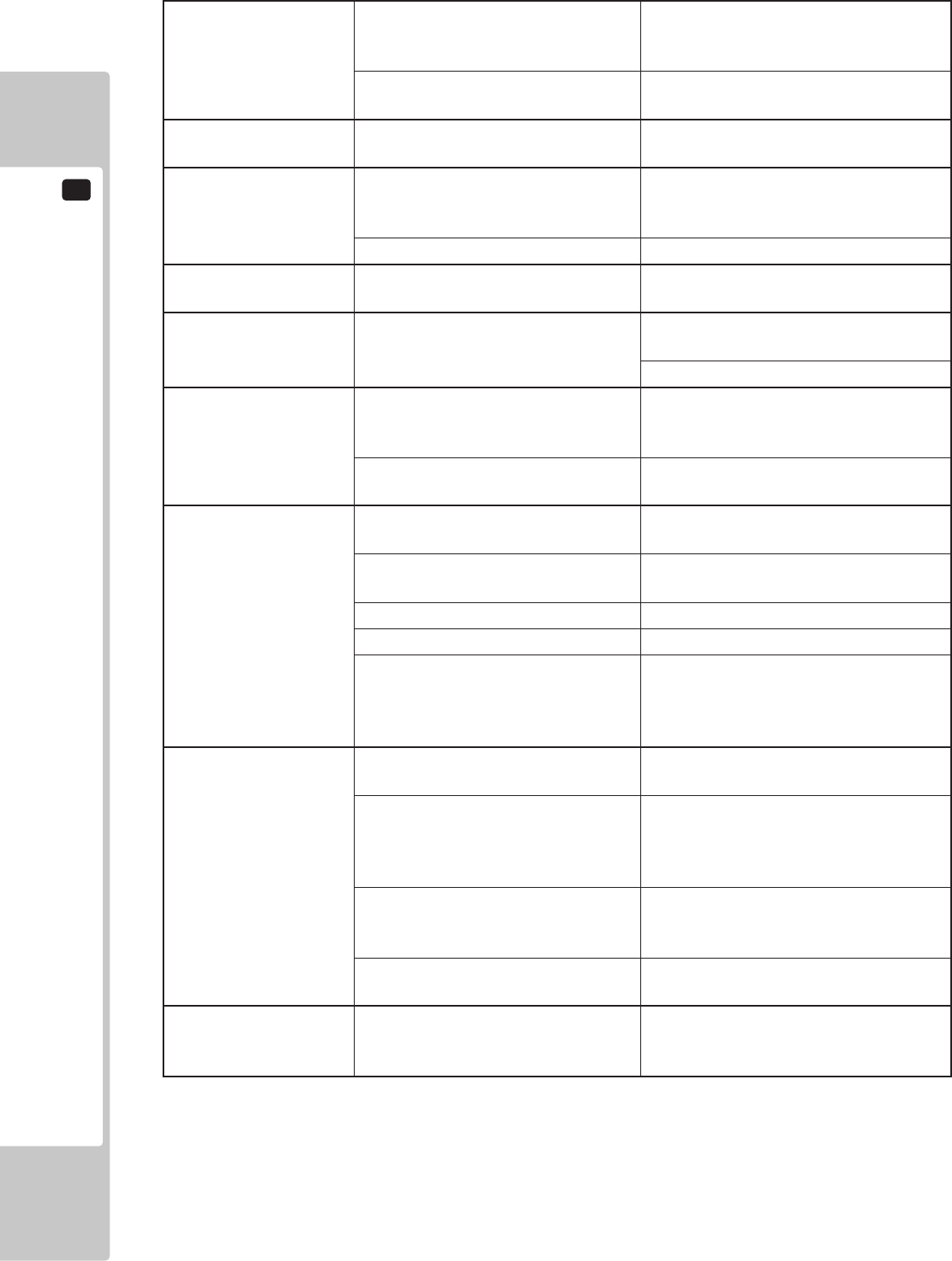
16
TROUBLESHOOTING
86
Sounds are emitted and
the lamps are lit, but the
screen is black.
Faulty connections for the visual
signal connector or the monitor power
connector.
Check the connections for the monitor
and game board connectors.
Broken monitor. Contact the company from whom the unit
was purchased.
Irregular/uneven colors
on the monitor screen.
Magnetization to the CRT. Press the Demagnetization switch on the
switch unit.
Colors on the monitor
screen are strange.
Faulty connection for the visual signal
connector.
Check the visual signal connector
connection and make sure it is secured
properly.
Screen adjustment is not appropriate. Make adjustment appropriately.
The on-screen image
sways and/or shrinks.
The power source and voltage are no
correct.
Make sure that the power supply and
voltage are correct.
Does not accept input
from any switch or
volume.
Faulty connector connections. Check the connection for the I/O Board
and Cabinet connector.
Check the power for the I/O Board.
Does not accept input
from the Shift Lever.
Faulty connector connections. Check the connections for the connectors
in the Control Panel and between the
Control Panel and the Cabinet.
Broken Microswitch. Replace the Microswitch.
<Microswitch 509-5704>
Steering (Servomotor)
response is incorrect.
Incomplete power on check. Power on and verify that the power on
check completes properly.
Deviation of the volume value. Adjust the volume value in the Test
Mode.
Volume gear engagement fault. Adjust the engagement of the gear.
Volume malfunctioning. Replace the volume.
Detached wires. Check for faulty wire connections around
moving parts.
When replacing wires, secure them so
that they do not touch any moving parts.
No response from
Steering (Servomotor).
Failure of power-on checking
procedure.
Reconnect the power and complete a
power-on checking procedure.
Faulty connector connections. Check the connections for the connectors
between the Game Board and Servodriver
and between the Servodriver and the
Servomotor.
Thermal element in the Servodriver is
operating.
Occurs when the internal temperature
reaches 70°C (158°F) and corrects
automatically when the unit cools.
Momentary overload caused a fuse on
the Servodriver to blow.
Contact the company from whom the unit
was purchased.
Steering (Servomotor)
is weak in its force
feedback.
Aging of the force feedback
mechanism.
Reset in the Test Mode. <See Chapter 9.>
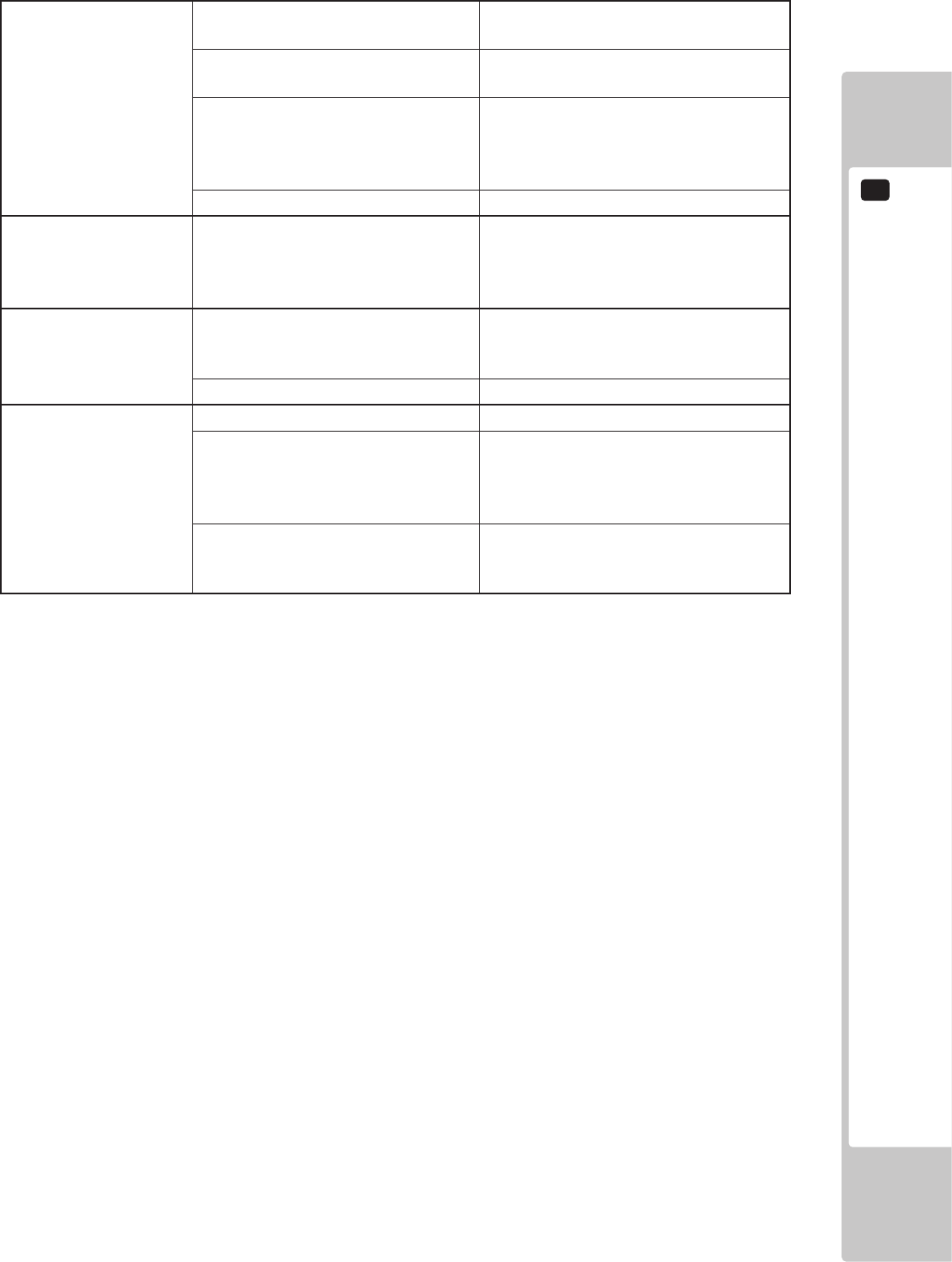
TROUBLE SHOOTING
16
87
The accelerator or
brake does not perform
appropriately.
Incorrect volume setting. Adjust the volume value in the Test
Mode.
Faulty Volume attachment or adjust
gear alignment.
Adjust the volume attachment and verify
in Test Mode.
Faulty connector connection. Check the connections for the accelerator
and brake connectors and the connectors
between the accelerator, brake and
cabinet.
Failure of the volume. Replace the volume.
Start button and View
Change button input
does not work and they
do not ash.
Faulty connector connections. Check the connections for the connectors
between the I/O Board, the cabinet and
the control panel and those inside the
control panel.
Start button and View
Change button input
works, but they do not
ash.
Unveried settings or operation. The Start button only ashes when Free
Play is set. Check the operation in Test
Mode.
The lamp is burnt out. Replace the lamp.
Failure of the network
play.
Network play is wrongly set. Reset correctly.
Communication cables are
disconnected.
Communication cables are wrongly
connected.
Reconnect the cables.
Damage of communication cables. Reconnect the cables correctly.
Replace the cables. Contact the company
from whom the unit was purchased.
16
TROUBLESHOOTING
88
• Incasefusereplacementsotherthanthosestatedinthismanualarenecessary,
contactwhereyoupurchasedtheproductfromforinquiriesregardingthis
matter.
• Inordertopreventanelectricshock,besuretoturnpoweroffandunplugfrom
thesocketoutletbeforeperformingworkbytouchingtheinternalpartsofthe
product.
• Becarefulsoasnottodamagewirings.Damagedwiringcancauseelectric
shockandshortcircuitaccidents.
• Besuretousefusesmeetingspeciedrating.Usingfusesexceedingthe
speciedratingcancausereandelectricshockaccidents.
• Aftereliminatingthecauseoftheblowingoffuse,replacethefuse.Depending
onthecauseoffuseblowing,continuedusewiththefuseasisblowncancause
generationofheatandrehazard.
Replacing Fuses
Fuses are located on the AC power plate on the back of the cabinet and on the transformer inside upper back lid..

TROUBLE SHOOTING
16
89
16-2 ERROR MESSAGES
This product displays the following messages when it detects an error. Read the error description and follow
the steps indicated. Refer to the LINDBERGH Service Manual for details on error messages displayed with the
LINDBERGH logo.
Error 11
JVS I/O board is not connected to main board.
The I/O board and the LINDBERGH have been disconnected.
Check to make sure the I/O board and the LINDBERGH are properly connected.
Error 12
JVS I/O board does not fulll the game spec.
The number of I/O boards are not sufcient to run the application.
Check to make sure the I/O board and the LINDBERGH are properly connected.
Error 15
Game Program Not Found.
The key chip intended for the application is not connected or is loose.
Check to make sure the key chip and the LINDBERGH are properly connected.
Error 1000
Network is Disconnected.
Communication has been broken.
This occurs when the packet does not arrive in a specic amount of time.
Check to make sure the network devices of all the cabinets are properly connected.
See the NOTE below.
Error 1001
MAIN-Cabinet Not Found.
The main cabinet (CABINET ID 1) was not found when the application was started or a timeout occurred
while waiting for communication. Communication will time out after approximately 2 minutes.
- In GAME TEST mode, check to make sure the main cabinet (CABINET ID 1) is properly set up.
- In the case of a time out, turn the power to all the connected cabinets off and then on again.
Error 1002
SUB-Cabinet Not Found.
The sub cabinets (CABINET ID 2-4) were not found when the application was started or a timeout occurred
while waiting for communication. Communication will time out after approximately 2 minutes.
- In GAME TEST mode, check to make sure the sub cabinets (CABINET ID 2-4) are properly set up.
- In the case of a time out, turn the power to all the connected cabinets off and then on again.

16
TROUBLESHOOTING
90
Error 1003
Same CabinetID Found.
The connected cabinets have the same CABINET ID.
In GAME TEST mode, set the CABINET IDs making sure that they are all different.
Error 1004
Network has not been initialized.
The network has not been initialized.
Check to make sure the network device on the LINDBERGH is functioning properly.
Error 1005
Network cannot use.
The network cannot be used.
Check to make sure the network device on the LINDBERGH is functioning properly.
NOTE: Thisgameissetupsothatifonecabinetcomesupwiththemessage,″Error1000Networkis
Disconnected,″thesamemessagewillappearonalltheothercabinetsaswell.Torecovertheconnection,
checkthenetworkdevicesconnectingthecabinets,andthenturnthepowerofftoallthecabinetsshowing
theerrorandthenonagain.
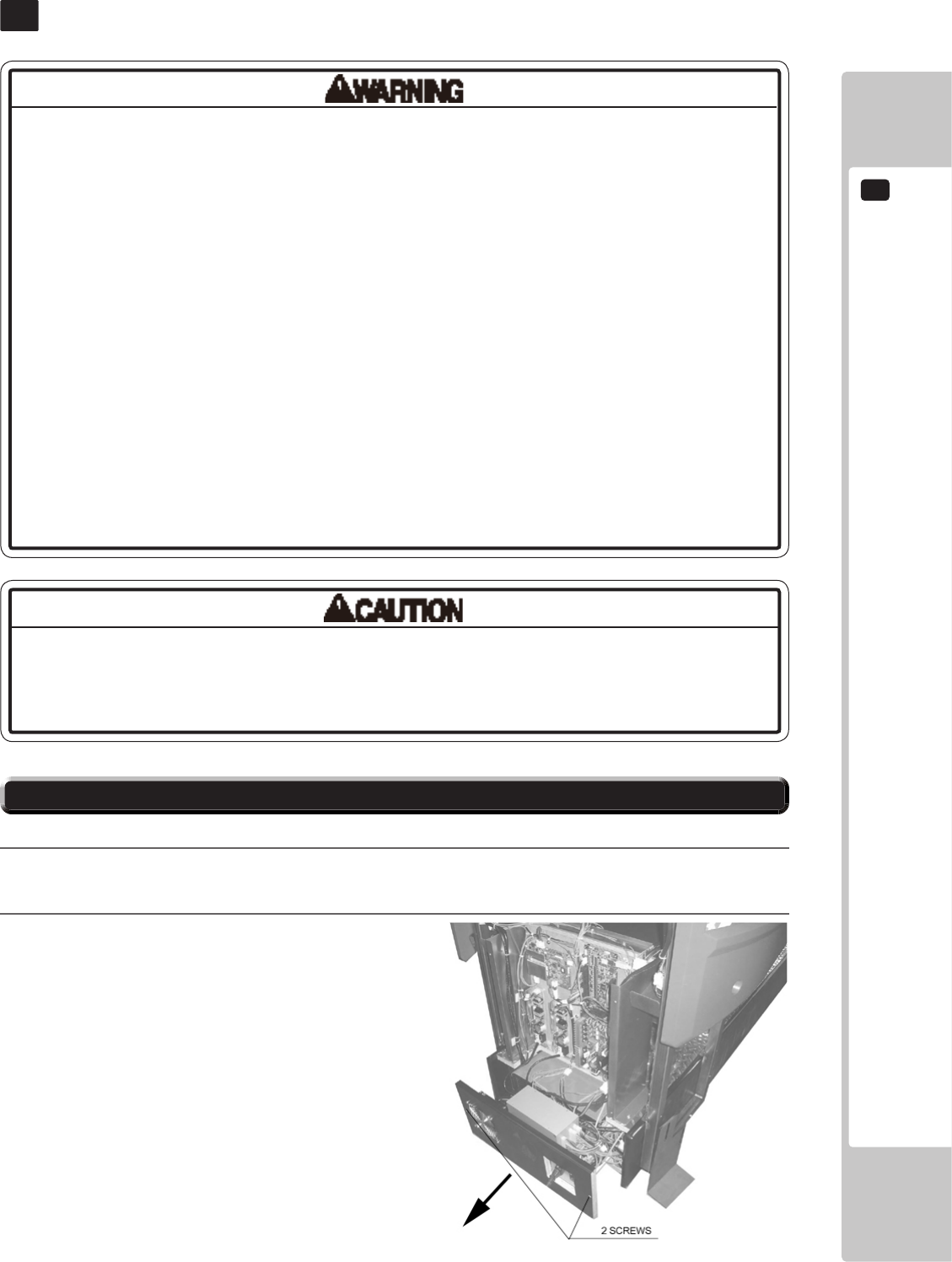
GAME BOARD
17
91
GAME BOARD
17
17-1 REMOVING THE LINDBERGH
Inthisproduct,settingchangesaremadeduringthetestmode.Thegameboard
neednotbeoperated.Usethegameboard,etc.asiswiththesamesettingmade
atthetimeofshipmentsoasnottocauseelectricshockandmalfunctioning.
• Inordertopreventelectricshockandshortcircuithazards,besuretoturn
poweroffbeforeperformingwork.
• Becarefulnottodamagethewires.Damagedwiresmaycauseelectricshock
orshortcircuitorpresentarerisk.
• Whenreplacingorrepairingthegameboardandthenreturningittothe
cabinet,besuretoreconnectalltheconnectorscorrectly.Improperconnection
maycauseelectricshock,shortcircuitorre.
• Whenconnectingtheconnector,checktheorientationcarefullyandconnect
securely.Theconnectormustbeconnectedintheproperdirection.Ifitis
connectedinthewrongdirectionorindiscriminatelyataninclinesothataload
isapplied,theconnectororitsterminalpinscouldbreak,causingashortcircuit
orre.
• Noconnectorsotherthanthoseconnectedonthegameboardwhenrst
deliveredcanbeusedbthisproduct.Donotconnectanyotherwirestoanyof
theunusedconnections.Thismayleadtothegenerationofheat,smokeorburn
outs.
1
Turn off the power.
2
Remove 2 truss screws and pull out the PCB base..
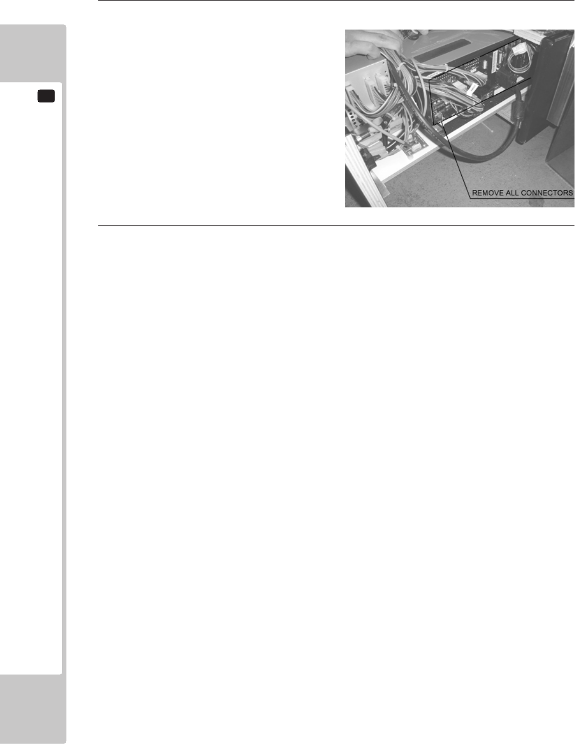
17
GAME BOARD
92
3
Remove all connectors connecting to the game board.
4
Remove 4 screws and remove the game board.
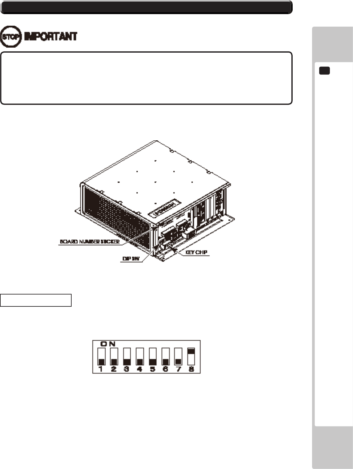
GAME BOARD
17
93
• Thegameboardbecomesthegameboardforthisproductoncethekeychip
isinserted.
• TheDIPSW(dipswitchesontheboardmustbesetasspeciedbelow.Ifset
incorrectlyforthisproduct,anerrorwillbedisplayedandthegamewillnotrun.
17-2 COMPOSITION OF THE GAME BOARD
ASSY CASE LBG L 1GB RTV (844-0019D-01) <USA>
DIP SW Setting
Use this product with the DIP SW settings shown in the gure below.
18-2 FIG. 02
18-2 FIG. 01
18
COMMUNICATION PLAY
94
COMMUNICATION PLAY
18
18-1 INSTALLATION PRECAUTIONS
• Toperformworksafely,besuretosecurethespacecorrespondingtonumber
ofmachinestobelinked.Failuretoobservethiscancauseaccident.
• Toavoidaccidents,useacablecoverthatwillnotcausepatronstotripwhen
layingnetworkcablesinareasofheavyfoottrafc.
• Topreventaccidentsandactsofvandalism,coverthenetworkcableswiththe
strongestcoverpossible.
• Beforestartingtowork,ensurethatthePowerSWisOFF.Failuretoobservethis
cancauseelectricshockorshortcircuit.
• Usecaresoasnottodamagewirings.Damagedwiringcancauseelectric
shockorshortcircuit.
• Donottouchundesignatedplaces.Touchingplacesnotdesignatedcancause
electricshockorshortcircuit.
• Theworkdescribedbelowshouldbecarriedoutbythesitemaintenance
personnelorotherqualiedprofessional.Workcarriedoutbypersonnelwithout
thenecessaryskillortechnologycancauseaccident.
• Toperformworksafelyandavoidseriousaccidentsuchasthecabinetfalling
down,donotperformworkinplaceswherestep-likegradedifferences,aditch,
orslopeexist.
• Topreventaccidentswhileworkingorwhileoperatingtheproductafterit
hasbeeninstalled,besurenottoconductanyproceduresotherthanthose
giveninthismanual.Therearecasesinwhichproceduresnotcoveredinthis
manualrequirespecialtoolsandskills.Ifaprocedurenotgiveninthismanualis
required,requestservicefromtheofcegiveninthismanualorfromthepointof
purchase.
For this game, up to 4 machines can be connected to allow up to 4 players to play simultaneously. In this instance,
connecting the communication cable and setting for the communication play are required.
Since 2 or more machines are to be linked, sufcient power corresponding to the number of machines used need to
be supplied. Note that as a standard, the per machine capacity should be 7 A for the 100-120 V area.
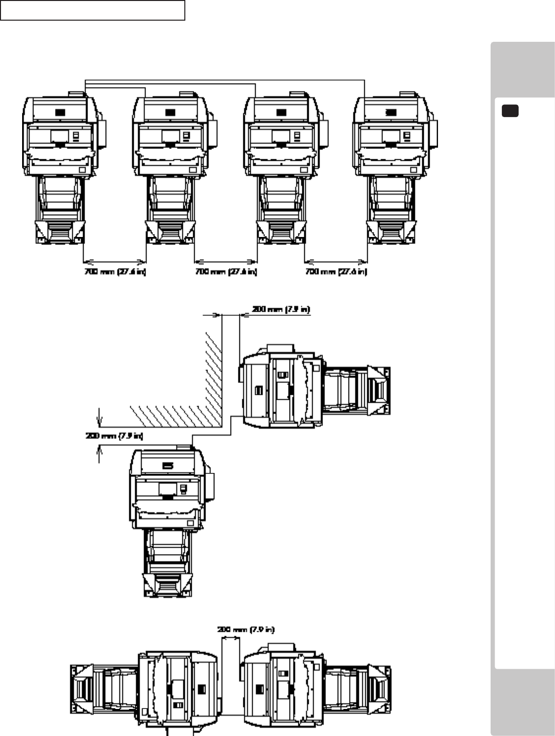
COMMUNICATION PLAY
18
95
Distance between Machines
The maximum distance between the game machines depends on the length of the cables connecting them, but make
sure the units are separated from each other by at least 70 cm (27.6 in) so that players can pass between them. Do
not install more than the designated number shown in the layout diagram.
19-1 FIG. 01

18
COMMUNICATION PLAY
96
18-2 CONNECTING THE COMMUNICATION CABLE
This game can be linked up to 4 units.
(For 2 units link play)
The LAN ports on the game boards in both unit must be connected with network (LAN) cable.
(For 3 or more units link play)
The hub is necessary to enable 3 or more units link play, but it is not included in the unit.
It must be prepared separately. (It is available at SEGA as an optional part (part#: 601-11351), if necessary)
Then the LAN port on the game board in each unit must be connected to the hub with network (LAN) cable.
COMMUNICATION PLAY
18
97
18-3 NETWORK PLAY SETTINGS
Each of the linked machines must be set up for network play. If the machines are not set up correctly, network play
will not be possible.
For this game, up to 4 machines can be connected to allow up to 4 players to play simultaneously.
1
Turn on the power on each machine to be used in network play.
2
Cause all of the machines to enter the Test Mode.
3
Select the GAME TEST MODE and press the Test button to display the GAME TEST MENU screen.
4
Select the GAME ASSIGNMENTS in the GAME TEST MENU screen and press the Test button.
5
Perform the CABINET ID setting. Set the different ID number to each machine. Be sure to assign one of
them with the ID number of “1.”
6
Cause all of the machines to exit from the TEST MODE. Always select EXIT in the SYSTEM TEST
MENU screen.
GAME ASSIGNMENTS
CABINET ID XXX
GAME DIFFICULTY NORMAL
CONTINUE ON
ADVERTISE SOUND ON
COMMENTARY VOLUME HIGH
NUM OF LAPS 3
HEAT 1
DRESS CODE LOW
SPEEDOMETER KM/H
CASUAL USER MODE OFF
DEFAULT SETTING
-> EXIT
19-3 FIG01 GAME ASSIGNMENTS Screen
18
COMMUNICATION PLAY
98
• Innetworkplay,difcultylevelandothersettingsaremadefromCABINETID
Number1.ChangingthesettingsatCABINETIDNumber1alsochangesthe
settingsforotherunits.
• IfoneoftheunitsattachedfornetworkplayentersTestMode,theotherunitwill
displaytheErrorscreen.
• Evenwhenunitsareconnectedfornetworkplay,eachseat,eachgamemay
begivendifferentcostsettings.Incorrectcostsettingsmaycausebudget
balancingproblems.
18-4 NETWORK PLAY PRECAUTIONS
The operation of a unit when connected to other units for network play is different than that of a stand-alone unit.
Administration of network units should be handled carefully.
Entering Test Mode will cause any other machines set up for network play to display the Error screen. When
customers are playing the game, do not enter Test Mode on any network play-enabled machine.
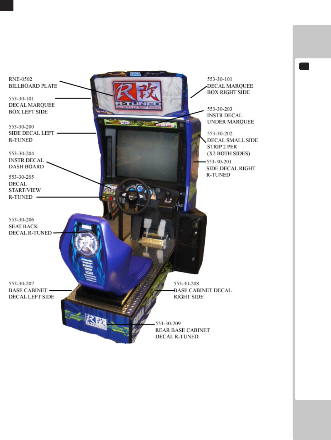
DESIGN-RELATED PARTS
19
99
DESIGN-RELATED PARTS
19
For the warning display stickers, refer to Chapter 1.
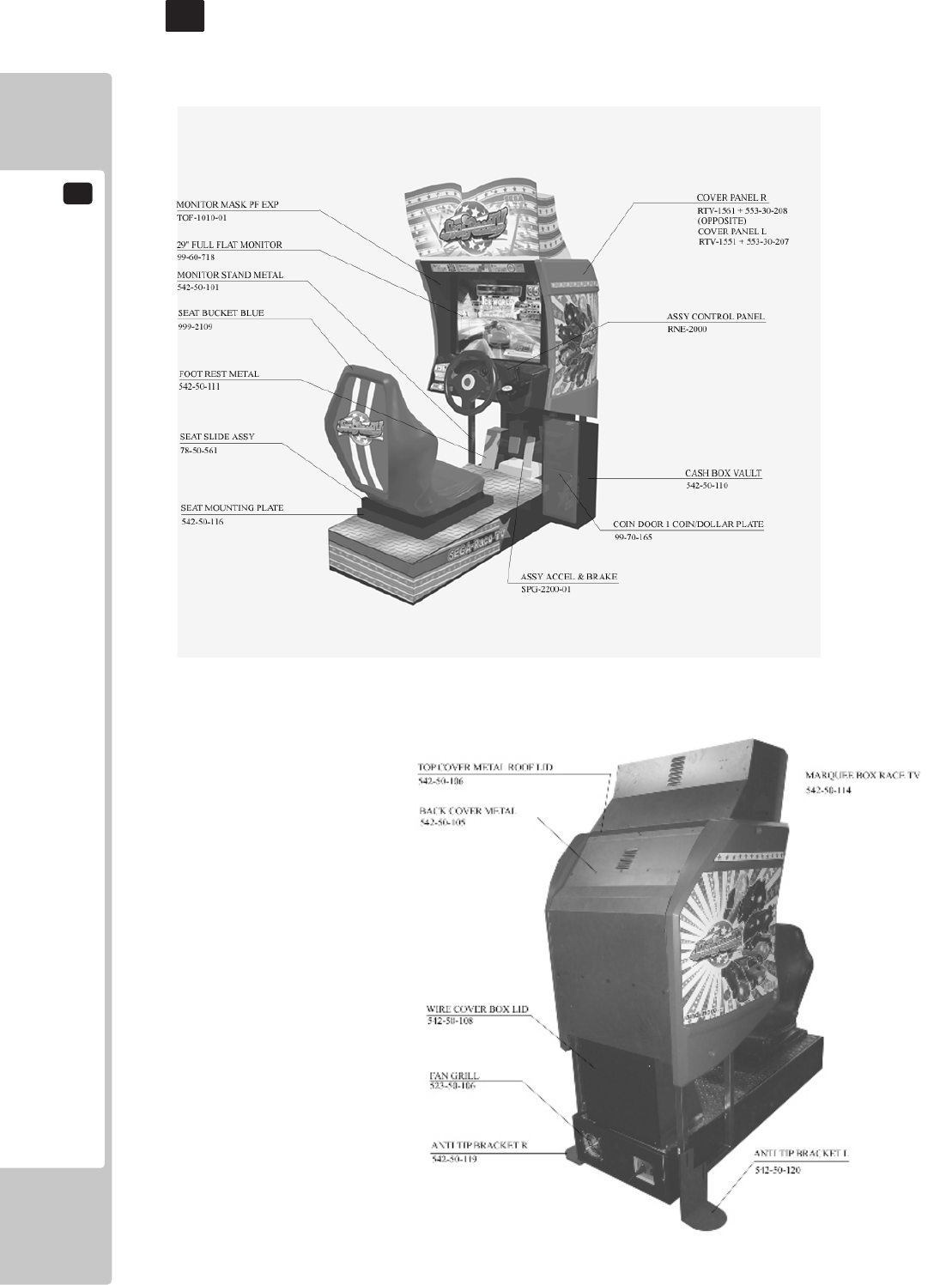
20
PARTS LIST
100
PARTS LIST
20
(CABINET PARTS)
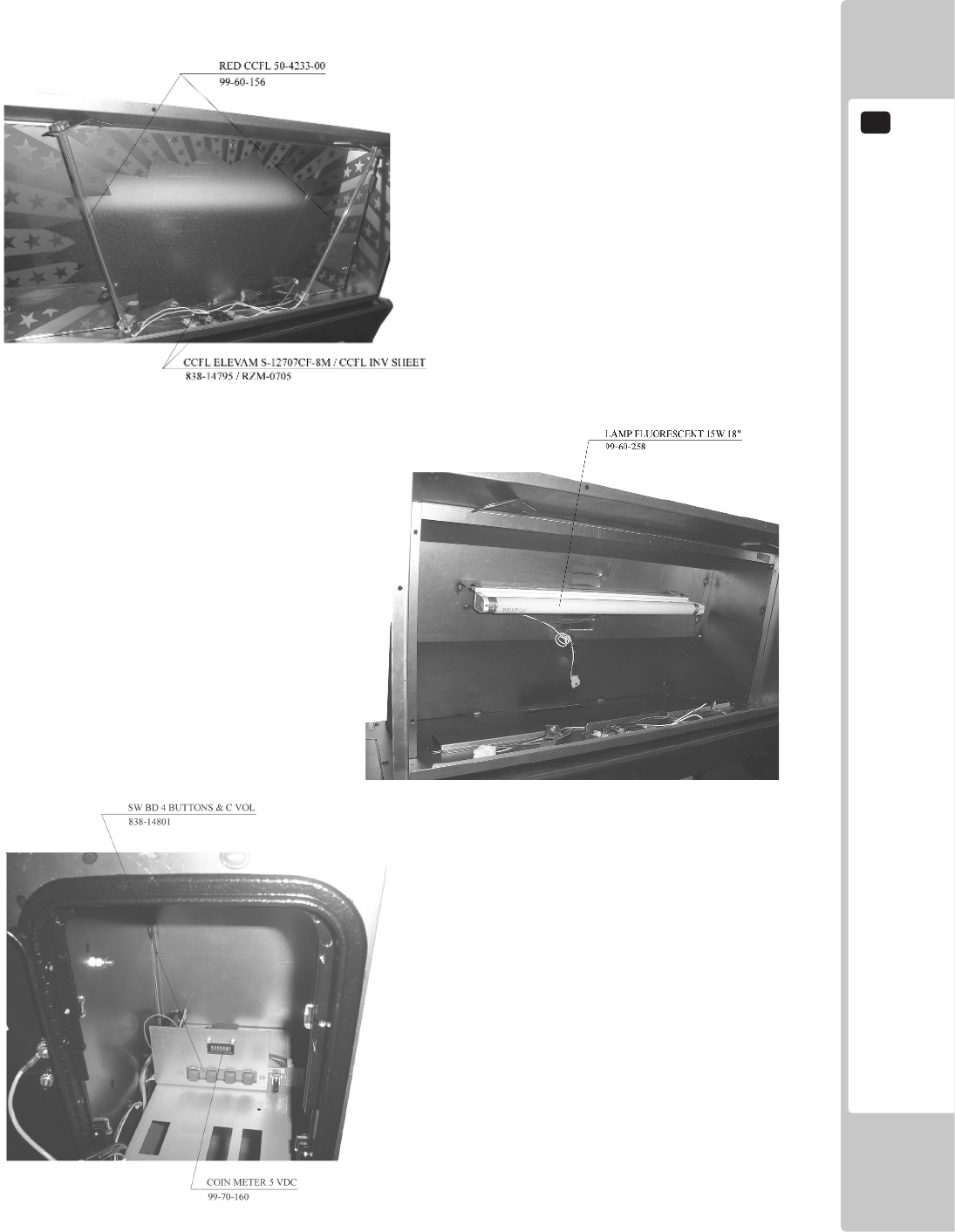
PARTS LIST
20
101
(INSIDE ELECTRIC COMPONENTS)
MARQUEE BOX
COIN BOX
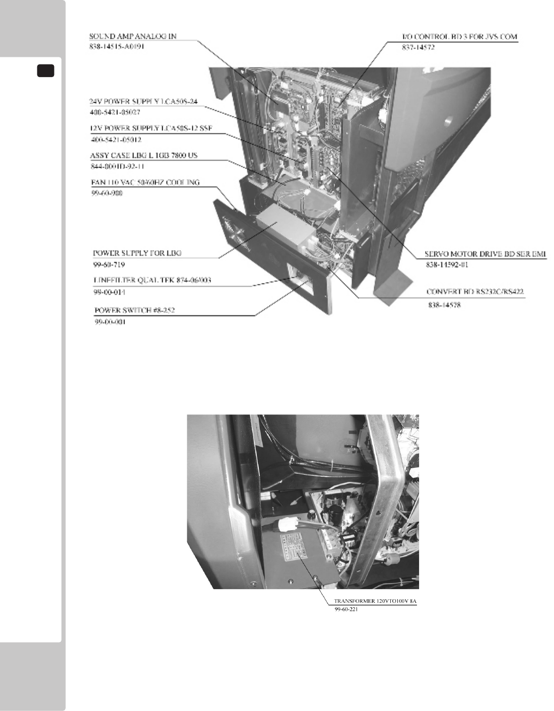
20
PARTS LIST
102
INSIDE THE CABINET BACK LOWER PORTION
INSIDE THE CABINET BACK UPPER PORTION
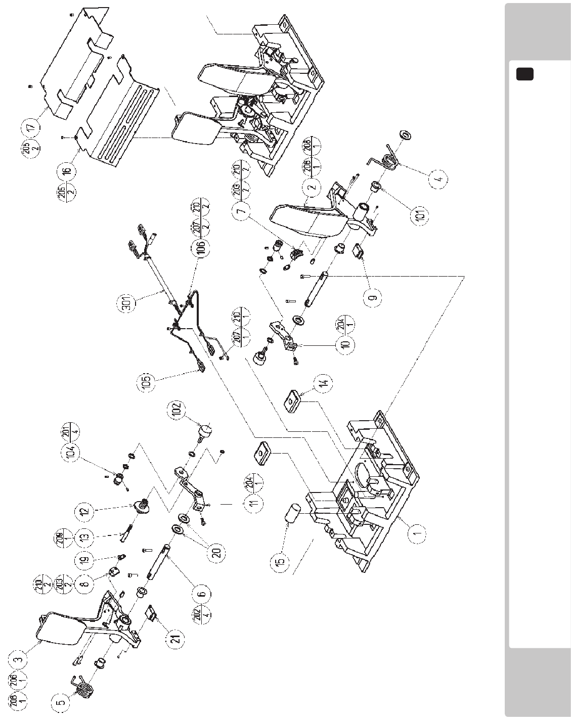
PARTS LIST
20
103
ASSY ACCEL&BRAKE (SPG-2200-01) (D-1/2)

20
PARTS LIST
104
ITEM NO. PART NO. DESCRIPTION NOTE
1 SPG-2201 BASE
2 SPG-2202 ACCEL PEDAL
3 SPG-2203 BRAKE PEDAL
4 SPG-2204 ACCEL SPRING
5 SPG-2205 BRAKE SPRING
6 SPG-2206 SHAFT
7 SPG-2207 ACCEL GEAR
8 SPG-2208 BRAKE GEAR
9 SPG-2209 NEUTRAL STOPPER
10 SPG-2210 VR PLATE ACCEL
11 SPG-2211 VR PLATE BRAKE
12 SPG-2212 AMPL GEAR
13 SPG-2213X GEAR SHAFT
14 SPG-2214 STOPPER
15 SPG-2215 RUBBER CUSHION
16 SPG-2216 COVER
17 SPG-2217 VR COVER
19 SPG-2219 GEAR STAY
20 SPG-2220 WSHR
21 SPG-2221 NEUTRAL STOPPER D
101 100-5263 BEARING 12(OILES 80F-1212)
102 220-5484 VOL CONT B-5K OHM
102 220-5753 VOL CONT B-5K OHM (TOCOS)
104 601-7944 GEAR 15
105 310-5029-F15 SUMITUBE F F15MM
106 280-0419 HARNESS LUG
201 028-A00304-P SET SCR HEX SKT CUP P M3x4
202 020-000520-0Z HEX SKT H CAP SCR BLK M5x20
203 000-P00420 M SCR PH M4x20
204 000-P00512-W M SCR PH W/FS M5x12
205 000-T00408-0C M SCR TH CRM M4x8
206 FAS-450005 SPR PIN BLK OZ 6x10
207 000-P00405 M SCR PH M4x5
208 FAS-000001 M SCR TH CRM M3x6
209 050-H00500 HEX NUT M5
210 060-F00400 FLT WSHR M4
301 600-6840-01 WIRE HARN ACCEL&BRAKE YL
ASSY ACCEL&BRAKE (SPG-2200-01) (D-2/2)
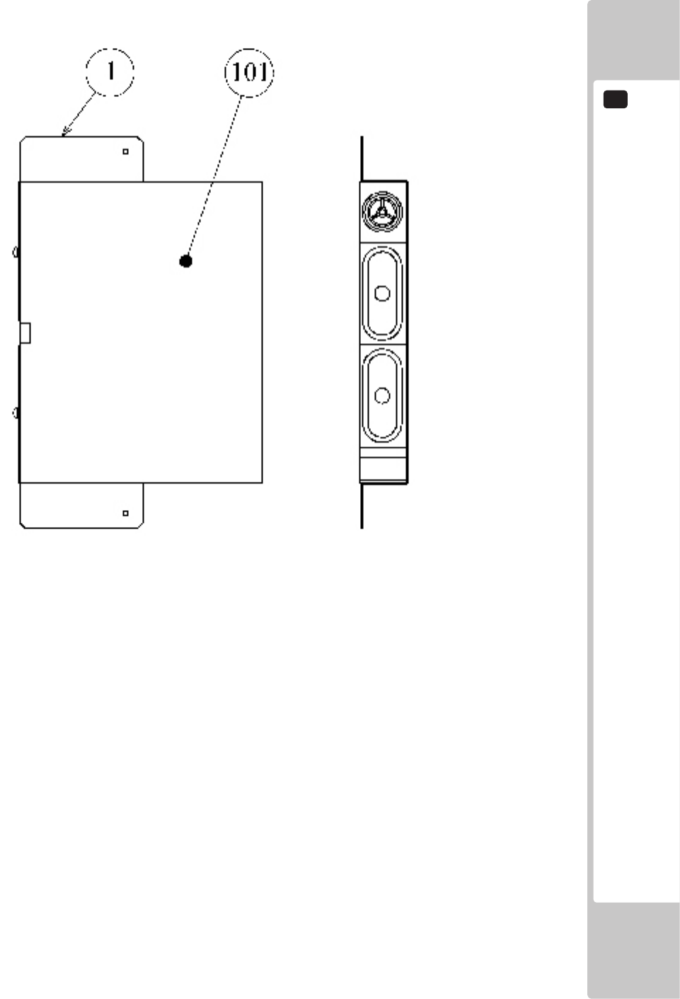
PARTS LIST
20
105
ITEM NO. PART NO. DESCRIPTION NOTE
1 542-50-104 SPEAKER HOLD DOWN METAL
101 130-5156-02 SPEAKER BOX 8OHM 20W VA1 YL
ASSY SPEAKER L
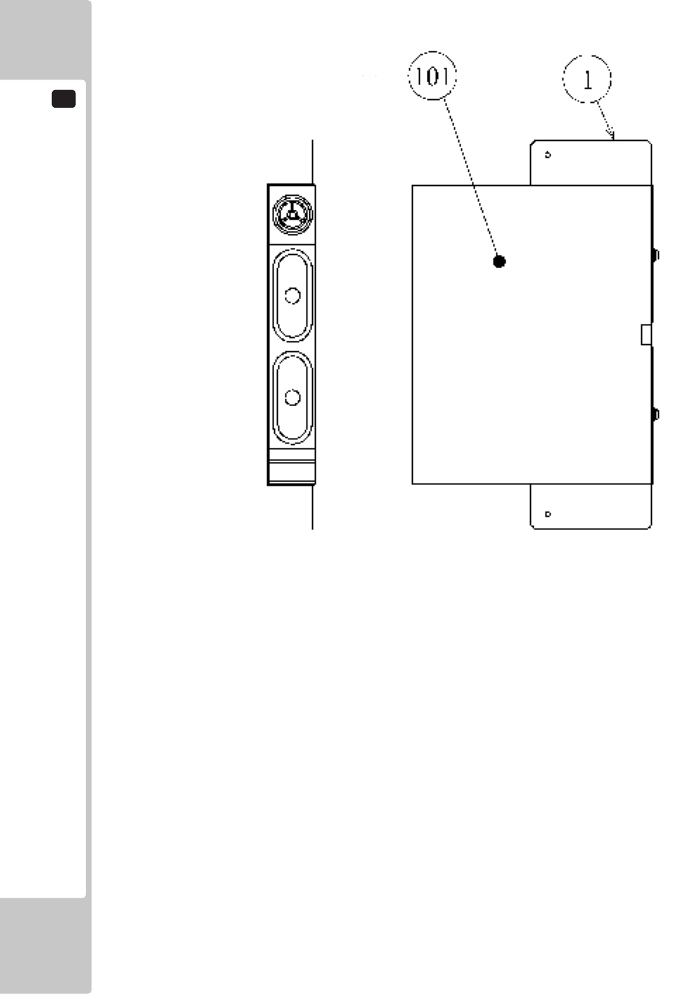
20
PARTS LIST
106
ITEM NO. PART NO. DESCRIPTION NOTE
1 542-50-104 SPEAKER HOLD DOWN METAL
101 130-5156-02 SPEAKER BOX 8OHM 20W VA1 YL
ASSY SPEAKER R
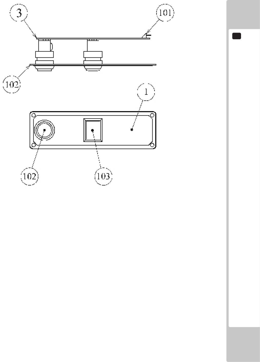
PARTS LIST
20
107
ITEM NO. PART NO. DESCRIPTION NOTE
1 RTV-2101 STICKER START/VIEW
2 ORT-2101 BUTTON PLATE
3 171-6478B PC BD LIGHTING SWX5
101 212-5205-12 CONN JST M 12P RTA
102 509-5560-Y-91 PB SW W/L 6V 1L Y ROHS
103 509-5561-R-91 PB SW W/L 6V 5L R ROHS
NOTE: When attaching the STICKER, line it up with the hole.
ASSY SW PLATE
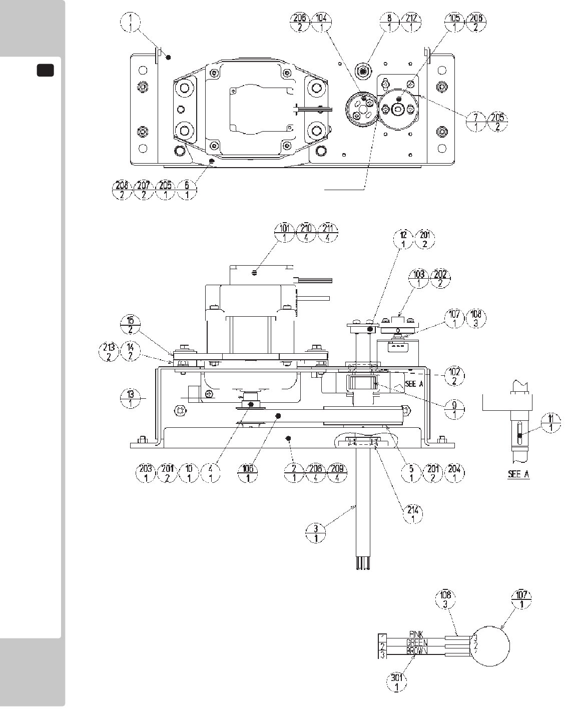
20
PARTS LIST
108
GREASING
NOTES:
1: Screw components must be coated with thread
sealant.
(Except for the U NUT)
2:FasteningTorque:M3:0.74N•mM4:1.8N•m
M6:5.6N•mM8:17.4N•m(8):20.0N•m
3: The motor shaft should be installed in a position
such that, when the steering wheel shaft is
centered, the key structure surface comes to ±45
degrees from the top.
4: Timing Belt S5M Initial Tension 95~165[N]
Span=130[mm] Belt width=15[mm]
Unit weight=0.034[kg/(10mm width x 1m length)]
(Mitsuboshi Belting Ltd.)
Unit weight=0.039[kg/(10mm width x 1m length)]
(Bando Chemical Industries, Ltd.)
ASSY HANDLE MECHA (RTV-2500) (D-1/2)

PARTS LIST
20
109
ASSY HANDLE MECHA (RTV-2500) (D-1/2)
ITEM NO. PART NO. DESCRIPTION NOTE
1 ORA-2501 HANDLE BASE
2 SPG-2502 BASE LID
3 ORA-2502 HANDLE SHAFT
4 SPG-2504 PULLEY 20 S5M
5 SPG-2505 PULLEY 60 S5M
6 ORA-2503 MOTOR BRKT
7 ORA-2504 VR BRKT
8 ORA-2505 STOPPER BOLT
9 ORA-2506 STOPPER RUBBER
10 SPG-2453 KEY 4x4x40
11 DYN-1270 STOPPER KEY
12 SLC-1130 ADJUST RING
13 ORA-2507 MOTOR SHAFT COLLAR
14 253-5592 MOTOR INSULATOR A
15 253-5593 MOTOR INSULATOR B
101 350-5805-02 SERVO MOTOR W/FG SIDE TYPE
102 100-5112 BEARING 17 (NSK 6003ZZ)
103 601-8966 GEAR HOLDER
104 601-6172 GEAR 48
105 601-6959 GEAR 64
106 601-9173 TIMING BELT (150 S5M 475)
107 220-5484 VOL CONT B-5K OHM
107 220-5753 VOL CONT B-5K OHM (TOCOS)
108 310-5029-F20 SUMITUBE F F 20MM
201 028-A00408-P SET SCR HEX SKT CUP P M4x8
202 028-A00308-P SET SCR HEX SKT CUP P M3x8
203 065-S012S0-Z STP RING BLK OZ S12
204 065-S020S0-Z STP RING BLK OZ S20
205 000-P00408-W M SCR PH W/FS M4x8
206 000-P00412-W M SCR PH W/FS M4x12
207 030-000612-S HEX BLT W/S M6x12
208 060-F00600 FLT WSHR M6
209 050-U00600 U NUT M6
210 030-000840-S HEX BLT W/S M8x40
211 068-852216 FLT WSHR 8.5-22x1.6
212 060-S01200 SPR WSHR M12
213 012-P00412 TAP SCR #2 PH 4x12
214 FAS-650023 WAVE WSHR 26.4-34.2x0.3
301 600-6866-01 WIRE HARN ASSY HANDLE MECHA VR
ASSY HANDLE MECHA (RTV-2500) (D-2/2)
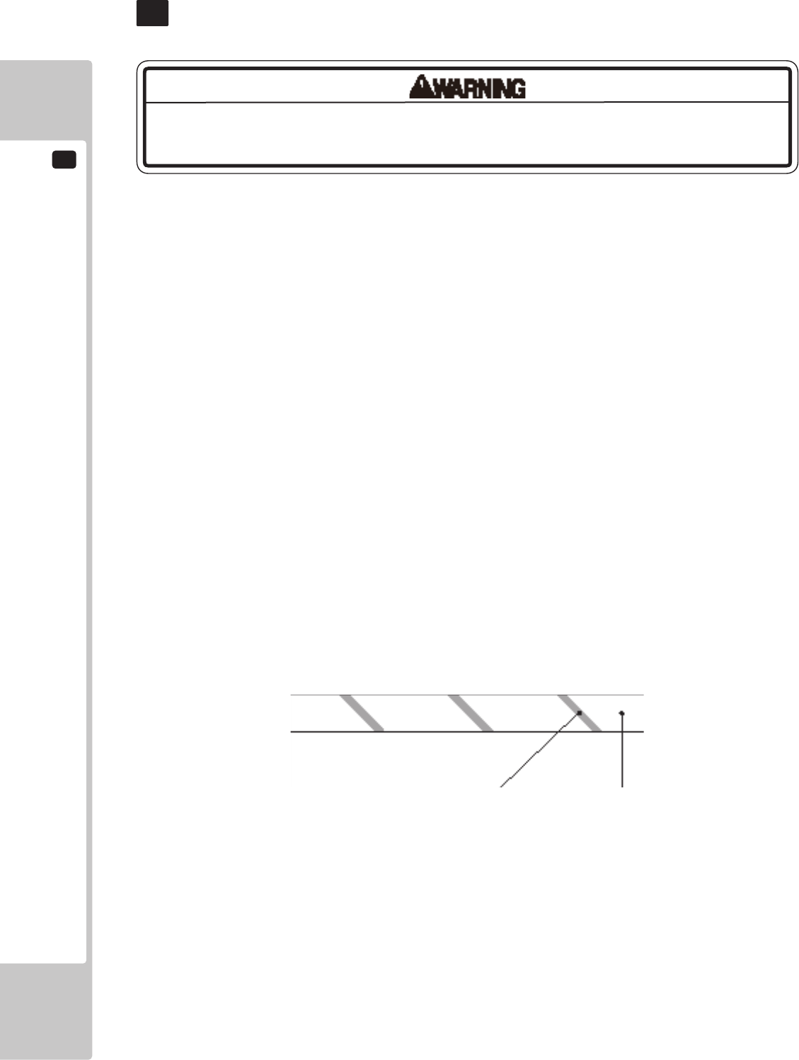
21
WIRE COLOR CODE TABLE
110
The color codes for the wires used in the diagrams in the following chapter are as follows.
A PINK
B SKY BLUE
C BROWN
D PURPLE
E LIGHT GREEN
Wires other than those of any of the above 5 single colors will be displayed by 2 alphanumeric characters.
1 RED
2 BLUE
3 YELLOW
4 GREEN
5 WHITE
7 ORANGE
8 BLACK
9 GRAY
If the right-hand side numeral of the code is 0, then the wire will be of a single color shown by the left-hand side
numeral (see the above).
Note 1: If the right-hand side numeral is not 0, that particular wire has a spiral color code. The left-hand side
character shows the base color and the right-hand side one, the spiral color.
<Example> 51………WHITE/RED
RED WHITE
Note 2: The character following the wire color code indicates the size of the wire.
U: AWG16
K: AWG18
L: AWG20
None: AWG22
The DC power wire color for this product is different from previous SEGA titles.
Working from the previous wire colors will create a high risk of re.
WIRE COLOR CODE TABLE
21
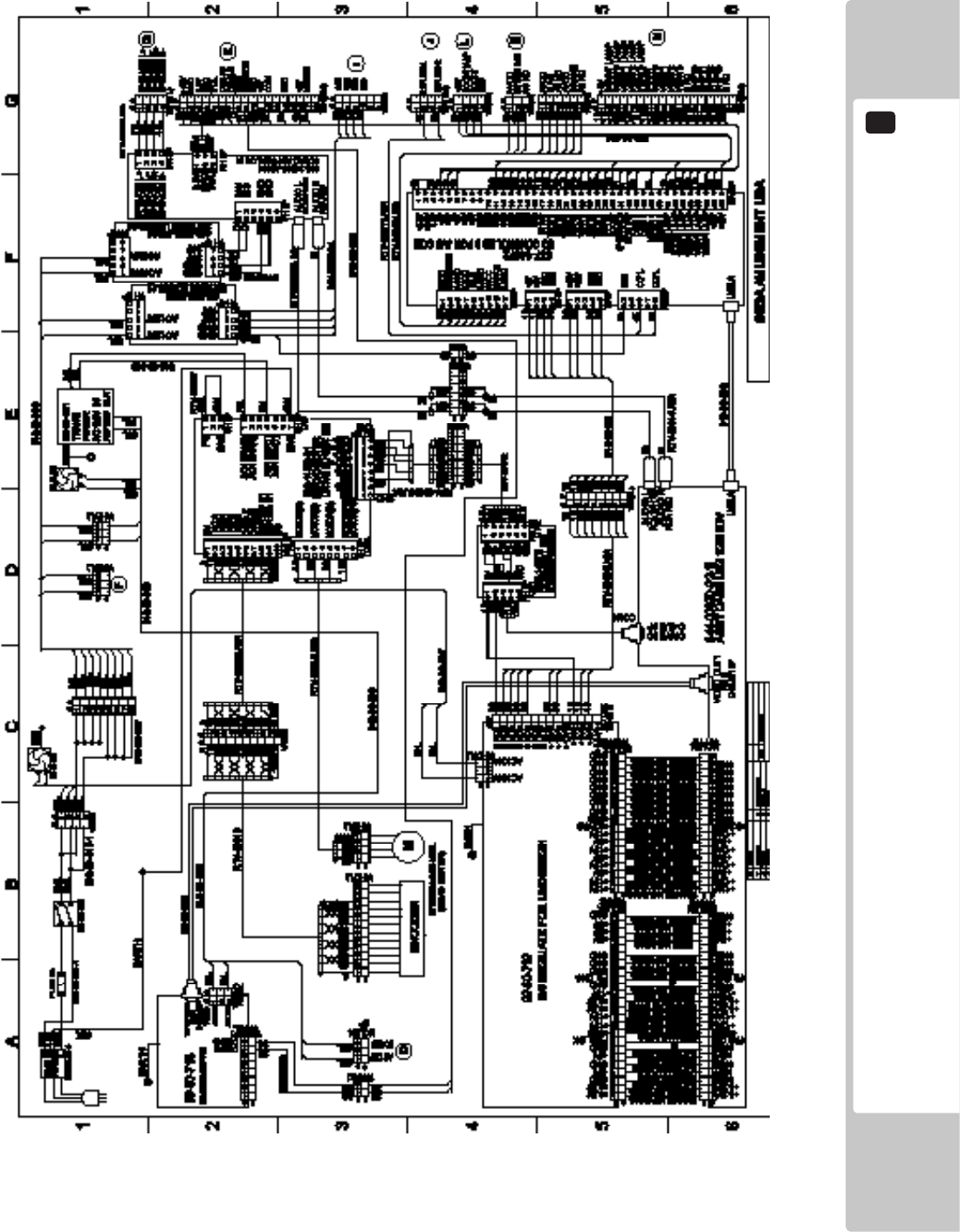
WIRING DIAGRAM
22
111
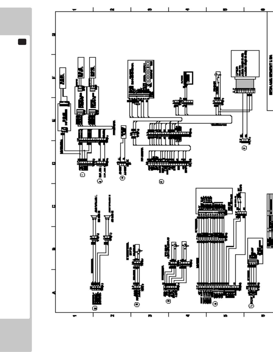
22
WIRING DIAGRAM
112
List of Third-Party Rights
Copyright (c) 1998, Todd C. Miller
All rights reserved.
Redistribution and use in source and binary forms, with or without modication, are permitted
provided that the following conditions are met:
Redistributions of source code must retain the above copyright notice, this list of conditions and
the following disclaimer.
Redistributions in binary form must reproduce the above copyright notice, this list of conditions
and the following disclaimer in the documentation and/or other materials provided with the
distribution.
Neither the name of the University of California, Berkeley nor the names of its contributors may
be used to endorse or promote products derived from this software without specic prior written
permission.
THIS SOFTWARE IS PROVIDED BY THE COPYRIGHT HOLDERS AND CONTRIBUTORS "AS IS" AND ANY
EXPRESS OR IMPLIED WARRANTIES, INCLUDING, BUT NOT LIMITED TO, THE IMPLIED WARRANTIES OF
MERCHANTABILITY AND FITNESS FOR A PARTICULAR PURPOSE ARE DISCLAIMED. IN NO EVENT SHALL
THE COPYRIGHT OWNER OR CONTRIBUTORS BE LIABLE FOR ANY DIRECT, INDIRECT, INCIDENTAL,
SPECIAL, EXEMPLARY, OR CONSEQUENTIAL DAMAGES (INCLUDING, BUT NOT LIMITED TO,
PROCUREMENT OF SUBSTITUTE GOODS OR SERVICES; LOSS OF USE, DATA, OR PROFITS; OR BUSINESS
INTERRUPTION) HOWEVER CAUSED AND ON ANY THEORY OF LIABILITY, WHETHER IN CONTRACT,
STRICT LIABILITY, OR TORT (INCLUDING NEGLIGENCE OR OTHERWISE) ARISING IN ANY WAY OUT OF
THE USE OF THIS SOFTWARE, EVEN IF ADVISED OF THE POSSIBILITY OF SUCH DAMAGE.
Copyright (C) 1991-2, RSA Data Security, Inc. Created 1991. All rights reserved.
License to copy and use this software is granted provided that it is identied as the "RSA Data
Security, Inc. MD5 Message-Digest Algorithm" in all material mentioning or referencing this
software or this function.
License is also granted to make and use derivative works provided that such works are identied
as "derived from the RSA Data Security, Inc. MD5 Message-Digest Algorithm" in all material
mentioning or referencing the derived work.
RSA Data Security, Inc. makes no representations concerning either the merchantability of this
software or the suitability of this software for any particular purpose. It is provided "as is" without
express or implied warranty of any kind.
Copyright (C) 1995-1997 Eric Young (eay@mincom.oz.au)
All rights reserved.
This package is an DES implementation written by Eric Young (eay@mincom.oz.au).
The implementation was written so as to conform with MIT's libdes.
This library is free for commercial and non-commercial use as long as the following conditions are
aheared to. The following conditions apply to all code found in this distribution.
Copyright remains Eric Young's, and as such any Copyright notices in the code are not to be
removed.
If this package is used in a product, Eric Young should be given attribution as the author of
that the SSL library. This can be in the form of a textual message at program startup or in
documentation (online or textual) provided with the package.
Redistribution and use in source and binary forms, with or without modication, are permitted
provided that the following conditions are met:
1. Redistributions of source code must retain the copyright notice, this list of conditions and the
following disclaimer.
2. Redistributions in binary form must reproduce the above copyright notice, this list of conditions
and the following disclaimer in the documentation and/or other materials provided with the
distribution.
3. All advertising materials mentioning features or use of this software must display the following
acknowledgement:
This product includes software developed by Eric Young (eay@mincom.oz.au)
THIS SOFTWARE IS PROVIDED BY ERIC YOUNG "AS IS" AND ANY EXPRESS OR IMPLIED WARRANTIES,
INCLUDING, BUT NOT LIMITED TO, THE IMPLIED WARRANTIES OF MERCHANTABILITY AND FITNESS FOR
A PARTICULAR PURPOSE ARE DISCLAIMED. IN NO EVENT SHALL THE AUTHOR OR CONTRIBUTORS
BE LIABLE FOR ANY DIRECT, INDIRECT, INCIDENTAL, SPECIAL, EXEMPLARY, OR CONSEQUENTIAL
DAMAGES (INCLUDING, BUT NOT LIMITED TO, PROCUREMENT OF SUBSTITUTE GOODS OR SERVICES;
LOSS OF USE, DATA, OR PROFITS; OR BUSINESS INTERRUPTION)HOWEVER CAUSED AND ON ANY
THEORY OF LIABILITY, WHETHER IN CONTRACT, STRICT LIABILITY, OR TORT (INCLUDING NEGLIGENCE
OR OTHERWISE) ARISING IN ANY WAY OUT OF THE USE OF THIS SOFTWARE, EVEN IF ADVISED OF THE
POSSIBILITY OF SUCH DAMAGE.
The license and distribution terms for any publically available version or derivative of this code
cannot be changed. i.e. this code cannot simply be copied and put under another distribution
license [including the GNU Public License.]
The reason behind this being stated in this direct manner is past experience in code simply
being copied and the attribution removed from it and then being distributed as part of other
packages. This implementation was a non-trivial and unpaid effort.
