Arcade Sonic Dash Extreme OSM.indb User Manual
2016-10-03
User Manual: Arcade Sonic Dash Extreme
Open the PDF directly: View PDF ![]() .
.
Page Count: 160 [warning: Documents this large are best viewed by clicking the View PDF Link!]
IMPORTANT
• Before using this product, read this manual carefully to understand the
contents herein stated.
• After reading this manual, be sure to keep it near the product or in a
convenient place for easy reference when necessary.
OWNER'S MANUALSONIC DASH EXTREME ARCADE 420-0024-01UK
Sega Amusements International Limited.
42 Barwell Business Park, Leatherhead Road, Chessington, Surrey, KT9 2NY. United Kingdom.
Telephone: +44 (0) 208 391 8090 Facsimile: +44 (0) 208 391 8089
email: sales@segaarcade.com Web: http://www.segaarcade.com
© SEGA
420-0024-01UK
1st PRINTING

BEFORE USING THE PRODUCT,
BE SURE TO READ THE FOLLOWING:
To maintain safety:
To ensure the safe operation of this product, be sure to read the following before usage.
The following instructions are intended for the users, operators and the personnel in charge of the
operation of the product. After carefully reading and suffi ciently understanding the warning displays
and cautions, handle the product appropriately. Be sure to keep this manual close to the product or
in a convenient place for future reference.
Herein, explanations which require special attention are enclosed with dual lines. Depending on
the potentially hazardous degrees, the terms of DANGER, WARNING, CAUTION, etc. are used.
Be sure to understand the contents of the displays before reading the text.
Indicates that mishandling the product by disregarding this pictograph will
cause severe injury or death.
Indicates that mishandling the product by disregarding this warning will cause
a potentially hazardous situation which can result in death or serious injury.
Indicates that mishandling the product by disregarding this caution will cause
a slight hazardous situation which can result in personal injury and/or material
damage.
For the safe usage of the product, the following pictographs are used:
Indicates "HANDLE WITH CARE." In order to protect the human body and equipment,
this display is attached to places where the instruction manual should be referred to.
Indicates a "protective earth terminal." Before operating the equipment, be sure to connect
it to the ground.
(The step may be omitted for products in which a power cable with earth is used.)
• Perform work in accordance with the instructions herein stated.
Instructions for work are explained by paying attention to the aspect of accident prevention.
Failing to perform work as per the instructions can cause accidents. In the case where only
those who have technical expertise should perform the work to avoid hazardous situation, the
instructions herein state that the site maintenance personnel should perform such work.
• Be sure to turn off the power before working on the machine.
To prevent an electric shock, be sure to turn off the power and unplug the power cable before
carrying out any work that requires direct contact with the interior of the product. If the work is
to be performed in the power-on status, the instruction manual herein always states to that effect.
• Be sure to ground the earth terminal.
(This is not required in the case where a power cable with earth is used.)
This product is equipped with the earth terminal. When installing the product, connect the earth
terminal to the "accurately grounded indoor earth terminal" by using an earth wire. Unless the
product is grounded appropriately, the user can be subject to an electric shock. After performing
repair, etc. for the control equipment, ensure that the earth wire is fi rmly connected to the control
equipment.
• Ensure that the power supply used is equipped with an earth leakage breaker.
Using a power supply which is not equipped with the earth leakage breaker can cause a fi re when
earth leakage occurs.
• Be sure to use fuses which meet the specifi ed rating.
(Only for the machines which use fuses.)
Using fuses exceeding the specifi ed rating can cause a fi re and an electric shock.
• Specifi cation changes (removal of equipment, conversion and addition) not
designated by SEGA are not allowed.
The parts of the product include warning labels for safety, covers for personal protection, etc. It
is very hazardous to operate the product by removing parts and/or modifying the circuits. Should
doors, lids and protective parts be damaged or lost, refrain from operating the product, and
contact where the product was purchased from or the offi ce herein stated.
SEGA shall not be held responsible for any accidents, compensation for damage to a third party,
resulting from the specifi cations not designated by SEGA.
• Ensure that the product meets the requirements of appropriate electrical
specifi cations.
Before installing the product, check for electrical specifi cations. SEGA products have a
nameplate on which electrical specifi cations are described. Ensure that the product is compatible
with the power supply voltage and frequency requirements of the location. Using any electrical
specifi cations different from the designated specifi cations can cause a fi re and an electric shock.
• Install and operate the product in places where appropriate lighting is available,
allowing warning labels to be clearly read.
To ensure safety for the customers, labels and printed instructions describing potentially
hazardous situations are applied to places where accidents can be caused. Ensure that where the
product is operated has suffi cient lighting allowing the warnings to be read. If any label is peeled
off, apply it again immediately. Please place an order with where the product was purchased from
or the offi ce herein stated.
• When handling the monitor, be very careful.
(Applies only to products with monitors.)
Some of the monitor parts are subject to high tension voltage. Even after turning off the power,
some portions are still subject to high tension voltage sometimes. Monitor repair and replacement
should be performed only by those technical personnel who have knowledge of electricity and
technical expertise.
• Be sure to adjust the monitor properly.
(Applies only to products with monitors.)
Do not operate the product leaving on-screen fl ickering or blurring as it is. Using the product
with the monitor not properly adjusted may cause dizziness or a headache to an operator, a
player, or the customers.
• When transporting or reselling this product, be sure to attach this manual to the
product.
* In the case where commercially available monitors and printers are used in this product, only the
contents relating to this product are explained herein. Some commercially available equipment
has functions and reactions not stated in this manual. Read this manual together with the specifi c
instruction manual of such equipment.
* Descriptions herein contained may be subject to improvement changes without notice.
* The contents described herein are fully prepared with due care. However, should any question
arise or errors be found, please contact SEGA.
INSPECTIONS IMMEDIATELY AFTER TRANSPORTING THE PRODUCT TO THE LOCATION
Normally, at the time of shipment, SEGA products are in a status allowing for usage immediately
after transporting to the location. Nevertheless, an irregular situation may occur during
transportation. Before turning on the power, check the following points to ensure that the product
has been transported in a satisfactory status.
Are there any dented portions or defects (cuts, etc.) on the external surfaces of the cabinet?
Are casters and adjusters damaged?
Do the power supply voltage and frequency requirements meet with those of the location?
Are all wiring connectors correctly and securely connected? Unless connected in the correct way,
connector connections can not be made accurately. Do not insert connectors forcibly.
Do power cables have cuts and dents?
Are all accessories available?
Can all doors and lids be opened with the accessory keys? Can doors and lids be fi rmly closed?
INTRODUCTION
iii
INTRODUCTION
This manual is intended to provide detailed descriptions together with all necessary information covering the general
operation of electronic assemblies, electro-mechanicals, servicing control, spare parts, etc. for the product,
"SONIC DASH EXTREME" Arcade
This manual is intended for the owners, personnel managers in charge of operation of this product.
Operate the product after carefully reading and suffi ciently understanding the instructions.
In the unlikely event that the product does not function correctly, DO NOT allow anyone other than a technician
to touch the internal system. Turn off the power to the machine, making sure to unplug the electrical cord from the
outlet, and contact the offi ce listed below or the point-of-purchase for this product.
Use of this product is unlikely to cause physical injuries or damage to property. However, points that require special
attention are indicated by bold text, the word “IMPORTANT” and the symbol below.
Indicates important information that, if ignored, may result in the mishandling
of the product and cause faulty operation or damage to the product.
Sega Amusements International Limited.
42 Barwell Business Park, Leatherhead Road, Chessington, Surrey, KT9 2NY. United Kingdom.
Telephone: +44 (0) 208 391 8090 Facsimile: +44 (0) 208 391 8089
email: sales@segaarcade.com Web: http://www.segaarcade.com
SPECIFICATIONS
Standard Cabinet
Machine Dimensions: 1,09m (42.9in.) [Width] x 1.70m (49.2in.) [Depth]
Machine Height: 2.6m (102.3.) (Installed)
Machine Weight: 159kg Approx (Installed)
Power, maximum current: AC115-240V 60~50Hz 1.1A (253W)
iv
INTRODUCTION
Parts replacement, maintenance inspections and troubleshooting should be carried out by site maintenance personnel
or other qualifi ed professionals. This manual includes directions for potentially dangerous procedures which should
only be carried out by professionals with the appropriate specialised knowledge.
The site maintenance personnel or other qualifi ed professionals mentioned in this manual are defi ned as follows:
Site maintenance personnel:
Individuals with experience in maintaining amusement equipment, vending machines, etc., working under the
supervision of the owner/operator of this product to maintain machines within amusement facilities or similar
premises by carrying out everyday procedures such as assembly, maintenance inspections, and replacement of units/
expendable parts.
Activities to be carried out by site maintenance personnel:
Amusement equipment/vending machine assembly, maintenance inspection and replacement of units/expendable
parts.
Other qualifi ed professionals:
Persons employed by amusement equipment manufacturers, or involved in design, production, testing or
maintenance of amusement equipment. The individual should have either graduated from technical school or hold
similar qualifi cations in electrical/electronics/mechanical engineering.
Activities to be carried out by other qualifi ed professionals:
Amusement equipment/vending machine assembly, repair/adjustment of electrical/electronic/mechanical parts.
Defi nition of 'Site Maintenance Personnel or Other Qualifi ed Individuals
Defi nition of 'Site Maintenance Personnel or Other Qualifi ed Individuals
Procedures not described in this manual or marked as ‘to be carried out by site
maintenance personnel or other qualifi ed professionals’ should not be carried
out by personnel without the necessary skill or technology. Work carried out by
unqualifi ed persons may cause serious accidents, including electrocution.
INTRODUCTION
v
Waste of Electrical and Electronic Equipment (WEEE) Statement.
Waste of Electrical and Electronic Equipment (WEEE) Statement.
The WEEE (Waste of Electrical and Electronic Equipment) directive places an obligation on all EU based
manufacturers and importers of Electrical and Electronic Equipment to take back products at the end of their
useful life. Sega Amusements Europe Ltd accepts its responsibility to fi nance the cost of treatment and recovery of
redundant WEEE in the United Kingdom in accordance with the specifi ed WEEE recycling requirements.
The symbol shown below will be on all products manufactured from 13th August 2005, which indicates this product
must NOT be disposed of with other normal waste. Instead, it is the user’s responsibility to dispose of their waste
equipment by arranging to return it to a designated UK collection point for the correct recycling of waste electrical
and electronic equipment.
For more information about where you can send your waste equipment for recycling contact your local authority
offi ce.
For non-UK users contact your local authority offi ce for information on the recycling of Waste Electrical and
Electronic Equipment.
Battery Recycling Statement.
Battery Recycling Statement.
The EC Directive on Batteries and Accumulators (2006/66/EC) aims to minimise the impact of batteries on
the environment and encourage the recovery of the materials they contain. To achieve increased collection and
recycling of waste batteries, the Directive places ‘producer responsibility’ obligations on manufacturers and
importers of portable, industrial and automotive batteries.
The symbol shown below will be on all equipment fi tted with batteries from 26th September 2008 and indicates
they must NOT be disposed of with other normal waste. Instead, it is the user’s responsibility to dispose of used
batteries by arranging to return them to a designated collection point for the correct recycling.
For more information about where you can send your waste batteries for recycling contact your local authority
offi ce.
REGISTERED IN ENGLAND REGISTERED NO. 1711515
REGISTERED OFFICE: BLOCK C 42 BARWELL BUSINESS PARK, CHESSINGTON, SURREY KT9 2NY

MICROSOFT SOFTWARE LICENSE AGREEMENT
WINDOWS EMBEDDED 8 STANDARD
Thank you for choosing a device preinstalled with Windows Embedded 8 Standard. This is a license agreement between you and SEGA. This agreement describes your rights to use the
Windows Embedded 8 Standard software included on this device. The Windows Embedded 8 Standard software also includes any separate media on which you received the software. For
your convenience, we’ve organized this agreement into two parts. The fi rst part includes introductory terms phrased in a question and answer format; the Additional Terms follow and contain
greater detail. You should review the entire agreement, including any linked terms, because all of the terms are important and together create this contract that applies to you. You can review
linked terms by pasting the forward link into your browser window once the software is running. The Additional Terms contain a binding arbitration clause and class action waiver. If
you live in the United States, these affect your rights to resolve a dispute with SEGA, or with Microsoft, and you should read them carefully.
By accepting this agreement or using the software, you agree to all of these terms and consent to the transmission of certain information for Internet-based features of the software.
If you do not accept and comply with these terms, you may not use the software or features. Instead, you may contact SEGA to determine its return policy for a refund or credit under
that policy.
How can I use the software? The software is licensed, not sold. Under this agreement, we grant you the right to install and run one copy only on the device with which you acquired the
software (the licensed device), for use by one person at a time, but only if you comply with all the terms of this agreement. The software is not licensed to be used as server software or for
commercial hosting – so, for example, you may not make the software available for simultaneous use by multiple users over a network. For more information on multiple user scenarios, see
the Additional Terms.
May I make a backup copy? Yes, you may make a single copy of the software for backup purposes, and use that backup copy as described below.
Can I transfer the software to another user? You may transfer the software directly to another user, only with the licensed device. The transfer must include the software, proof of pur-
chase, and, if provided with the device, an authentic Windows label such as the certifi cate of authenticity label, including the product key. You may not keep any copies of the software or any
earlier version. Before any permitted transfer, the other party must agree that this agreement applies to the transfer and use of the software.
Does the software collect my personal information? If you connect your licensed device to the Internet, some features of the software may connect to Microsoft or service provider com-
puter systems to send or receive information, including personal information. You may not always receive a separate notice when they connect. If you choose to use any of these features, you
agree to send or receive this information when using that feature. Many of these features can be switched off or you can choose not to use them.
How does Microsoft use your information? Microsoft uses the information it collects through the software features to upgrade or fi x the software and otherwise improve its products and
services. In certain circumstances, Microsoft also shares it with others. For example, Microsoft shares error reports with relevant hardware and software vendors, so that the vendors can use
the information to improve how their products run with Microsoft products. You agree that Microsoft may use and disclose the information as described in Microsoft’s Privacy Statement at
go.microsoft.com/fwlink/?LinkId=190175.
What does this agreement apply to? The Windows Embedded 8 Standard software on this licensed device includes software licensed from Microsoft Corporation or its affi liate. This agree-
ment (including any printed-paper license terms that accompany the software) applies to the software, any separate media on which you received the software, and any Microsoft updates,
supplements, and services for the software, unless other terms come with them.
Are there things I’m not allowed to do with the software? Yes. Because the software is licensed, not sold, SEGA and Microsoft reserve all rights (such as rights under intellectual property
laws) not expressly granted in this agreement. In particular, this license does not give you any right to, and you may not: use features of the software separately; publish, copy (other than the
permitted backup copy), rent, lease, or lend the software; transfer the software (except as permitted by this agreement); attempt to circumvent technical protection measures in the software;
or reverse engineer, decompile, or disassemble the software, except if the laws where you live permit this even when this agreement does not. In that case, you may do only what your law al-
lows. When using Internet-based features , you may not use those features in any way that could interfere with anyone else’s use of them, or to try to gain access to any service, data, account,
or network in an unauthorized manner.
ADDITIONAL TERMS
1. License Rights and Use Scenarios
a. Device. In this agreement, “device” means a hardware system with internal storage capable of running the software. The software is licensed to run on up to two
processors on the licensed device at any one time.
b. Specifi c Use. SEGA designed the licensed device for a specifi c use. You may only use the software for that use.
c. Other Software. You may use other programs with the software as long as the other programs
• directly support the specifi c use for the licensed device, or
• provide system utilities, resource management, or anti-virus or similar protection.
Software that provides consumer or business tasks or processes may not run on the licensed device. This includes word processing, spreadsheet, database,
scheduling and personal fi nance software. The licensed device may use terminal services protocols to access such software running on a server.
d. Device connections. You may not use the software as server software. In other words, more than one device may not access, display, run, share or use the soft
ware at the same time. You may allow up to 20 other devices to access the software installed on the licensed device for the purpose of using fi le services, print
services, Internet information services, and Internet connection sharing and telephony services on the licensed device. The 20 connection limit applies to devices
that access the software indirectly through “multiplexing” or other software or hardware that pools connections. You may use unlimited inbound connections at
any time via TCP/IP.
e. Remote Access Technologies. The software contains Remote Desktop and Remote Assistance technologies that enable the software or applications installed on
the licensed device to be accessed remotely from other devices.
• Remote Desktop. The single primary user of the licensed device may access a session from any other device using Remote Desktop or similar tech-
nologies. A “session” means the experience of interacting with the software, directly or indirectly, through any combination of input, output and display
peripherals. Other users, one at a time, may access the licensed software running on this host device, from any device using Remote Desktop, but only
if the remote device is separately licensed to run Windows Embedded 8 Standard.
• Remote Assistance. You may use Remote Assistance or similar technologies to share an active session without obtaining any additional licenses for the
software. Remote Assistance allows one user to directly connect to another user’s device, usually to correct problems.
2. Binding Arbitration and Class Action Waiver
a. Application. This Section 2 applies to any dispute EXCEPT IT DOES NOT INCLUDE A DISPUTE RELATING TO THE ENFORCEMENT OR VALIDITY
OF YOUR, SEGA’S, OR EITHER OF OUR LICENSORS’ INTELLECTUAL PROPERTY RIGHTS. Dispute means any dispute, action, or other controversy
between you and SEGA, or you and Microsoft, concerning the software (including its price) or this agreement, whether in contract, warranty, tort, statute,
regulation, ordinance, or any other legal or equitable basis. “Dispute” will be given the broadest possible meaning allowable under law.
b. Notice of Dispute. In the event of a dispute, you or SEGA must give the other a Notice of Dispute, which is a written statement of the name, address, and
contact information of the party giving it, the facts giving rise to the dispute, and the relief requested. Send it by U.S. Mail to SEGA, ATTN: LEGAL DEPART
MENT. SEGA will send any Notice of Dispute to your U.S. Mail address if available, or otherwise to your e-mail address. You and SEGA will attempt to
resolve any dispute through informal negotiation within 60 days from the date the Notice of Dispute is sent. After 60 days, you or SEGA may commence
arbitration.
c. Small claims court. You may also litigate any dispute in small claims court in your county of residence or the SEGA’s principal place of business, if the dispute
meets all requirements to be heard in the small claims court. You may litigate in small claims court whether or not you negotiated informally fi rst.
d. Binding arbitration. If you and SEGA, or Microsoft, do not resolve any dispute by informal negotiation or in small claims court, any other effort to resolve the
dispute will be conducted exclusively by binding arbitration. You are giving up the right to litigate (or participate in as a party or class member) all disputes in
court before a judge or jury. Instead, all disputes will be resolved before a neutral arbitrator, whose decision will be fi nal except for a limited right of appeal
under the Federal Arbitration Act. Any court with jurisdiction over the parties may enforce the arbitrator’s award.
e. Class action waiver. Any proceedings to resolve or litigate any dispute in any forum will be conducted solely on an individual basis. Neither you, SEGA, nor
Microsoft, will seek to have any dispute heard as a class action, as a private attorney general action, or in any other proceeding in which any party acts or pro
poses to act in a representative capacity. No arbitration or proceeding will be combined with another without the prior written consent of all parties to all af
fected arbitrations or proceedings.
f. Arbitration procedure. Any arbitration will be conducted by the American Arbitration Association (the “AAA”), under its Commercial Arbitration Rules.
If you are an individual and use the software for personal or household use, or if the value of the dispute is $75,000 or less whether or not you are an individual
or how you use the software, the AAA Supplementary Procedures for Consumer-Related Disputes will also apply. To commence arbitration, submit a Com
mercial Arbitration Rules Demand for Arbitration form to the AAA. You may request a telephonic or in-person hearing by following the AAA rules. In a dispute
involving $10,000 or less, any hearing will be telephonic unless the arbitrator fi nds good cause to hold an in-person hearing instead. For more information, see
adr.org or call 1-800-778-7879. You agree to commence arbitration only in your county of residence or in the SEGA’s principal place of business. SEGA agrees
to commence arbitration only in your county of residence. The arbitrator may award the same damages to you individually as a court could. The arbitrator may
award declaratory or injunctive relief only to you individually, and only to the extent required to satisfy your individual claim.
vi
MICROSOFT SOFTWARE LICENSE AGREEMENT
g. Arbitration fees and incentives
i. Disputes involving $75,000 or less. SEGA will promptly reimburse your fi ling fees and pay the AAA’s and arbitrator’s fees and expenses. If you
reject the SEGA’s last written settlement offer made before the arbitrator was appointed (“last written offer”), your dispute goes all the way to an
arbitrator’s decision (called an “award”), and the arbitrator awards you more than the last written offer, SEGA will give you three incentives: (1) pay
the greater of the award or $1,000; (2) pay twice your reasonable attorney’s fees, if any; and (3) reimburse any expenses (including expert witness
fees and costs) that your attorney reasonably accrues for investigating, preparing, and pursuing your claim in arbitration. The arbitrator will deter
mine the amounts.
ii. Disputes involving more than $75,000. The AAA rules will govern payment of fi ling fees and the AAA’s and arbitrator’s fees and expenses.
iii. Disputes involving any amount. In any arbitration you commence, SEGA will seek its AAA or arbitrator’s fees and expenses, or your fi ling fees it
reimbursed, only if the arbitrator fi nds the arbitration frivolous or brought for an improper purpose. In any arbitration SEGA commences, it will pay
all fi ling, AAA, and arbitrator’s fees and expenses. It will not seek its attorney’s fees or expenses from you in any arbitration. Fees and expenses are
not counted in determining how much a dispute involves.
h. Claims or disputes must be fi led within one year. To the extent permitted by law, any claim or dispute under this agreement to which Section 2 applies must be
fi led within one year in small claims court (Section 2.c) or in arbitration (Section 2.d). The one-year period begins when the claim or dispute fi rst could be fi led. If
such a claim or dispute is not fi led within one year, it is permanently barred.
i. Severability. If the class action waiver in Section 2.e is found to be illegal or unenforceable as to all or some parts of a dispute, then Section 2 will not apply to those
parts. Instead, those parts will be severed and proceed in a court of law, with the remaining parts proceeding in arbitration. If any other provision of Section 2 is
found to be illegal or unenforceable, that provision will be severed with the remainder of Section 2 remaining in full force and effect.
j. Third-Party Benefi ciary. Microsoft Corporation is not a party to this agreement but is a third-party benefi ciary of your and the SEGA’s agreement to resolve disputes
through informal negotiation and arbitration. If your dispute is with Microsoft, Microsoft agrees to do everything SEGA agrees to do in Section 2, and you agree to
do everything regarding Microsoft that Section 2 requires you to do regarding SEGA. Mail a Notice of Dispute with Microsoft to Microsoft Corporation, ATTN:
LCA ARBITRATION, One Microsoft Way, Redmond, WA 98052-6399. You may commence an arbitration or small claims court case against Microsoft in your
county of residence or King County, Washington.
3. CHOICE OF LAW
The laws of the state or country where you live govern all claims and disputes under this agreement, including breach of contract claims and claims under state consumer protection laws, unfair
competition laws, implied warranty laws, for unjust enrichment, and in tort. If you acquired the software in any other country, the laws of that country apply. This agreement describes certain le-
gal rights. You may have other rights, including consumer rights, under the laws of your state or country. You may also have rights with respect to the party from whom you acquired the software.
This agreement does not change those other rights if the laws of your state or country do not permit it to do so.
4. INTERNET-BASED FEATURES; PRIVACY
The following software features use Internet protocols, which send to Microsoft (or its suppliers or service providers) device information, such as your Internet protocol address, the type of
operating system, browser and name and version of the software you are using, and the language code of the device where the software is installed. Microsoft uses this information to make the
Internet-based features available to you, in accordance with the Windows 8 Privacy Statement, at go.microsoft.com/fwlink/?LinkId=190175. Some Internet-based features may be delivered at a
later date via Microsoft’s Windows Update service—if, for example, you acquire an application that relies on one of those services. SEGA may have elected to turn on one or more of the follow-
ing features in the licensed device.
a. Windows Update. If you use the Windows Update service in the software, updates or downloads to the Windows Update service will be required for proper func
tioning of the service, from time to time, and will be downloaded and installed without further notice to you.
b. Windows Digital Rights Management technology. Some content owners use Windows digital rights
management technology (WDRM) to protect their copyrights and other intellectual property, including by disabling the software’s ability to play protected content if
WDRM fails. You agree that Microsoft may include a revocation list with the licenses.
c. Windows Media Player. When you use Windows Media Player, it checks with Microsoft for compatible online music services in your region and new versions of
the player. You may only use Windows Media Player as described at go.microsoft.com/fwlink/?LinkId=104605.
d. Windows Defender. If turned on, Windows Defender will search your licensed device for many types of malicious software, including viruses, worms, bots, rootkits,
“spyware”, “adware” and other potentially unwanted software. If it fi nds potentially unwanted software, the software will ask you if you want to ignore, disable
(quarantine) or remove it. If you choose the “recommended” security settings when you fi rst start using the software, such malware and other potentially unwanted
software rated “high” or “severe” will automatically be removed. This removal may result in other software on your licensed device ceasing to work or your breach
ing a license to use that software. It is possible that software that is not unwanted may be removed or disabled. If you use Windows Defender and Windows Update,
Windows Defender is regularly updated through Windows Update.
e. Malicious software removal. If you use Windows Update, at least once each month the software will scan for and remove from your licensed device the malware
listed at go.microsoft.com/fwlink/?LinkId=241725. After the scan completes, a report will be sent to Microsoft with specifi c information about malware detected,
errors, and other information about your device. This information is used to improve the software and other Microsoft products. You may disable the software’s
reporting functionality by following the instructions found at go.microsoft.com/fwlink/?LinkId=241725.
f. SmartScreen Filter. If enabled, the SmartScreen Filter will check the addresses of webpages and downloads you attempt to view against a frequently updated list
of webpages and downloads that have been reported to Microsoft as unsafe or suspicious. SmartScreen will also check downloaded programs that you attempt to
run against a list of commonly downloaded or run programs to help you make more informed trust decisions. More information can be found by visiting the Internet
Explorer Privacy Statement go.microsoft.com/fwlink/?LinkId=239590. By enabling SmartScreen in either Windows or Internet Explorer, you consent to this fea
ture, and you agree to use the SmartScreen Filter only in conjunction with Windows or Internet Explorer. You may not, either manually or by enabling or author
izing any software or service, copy, display, distribute, collect or store any data provided by the SmartScreen Filter.
g. IPv6 Network Address Translation (NAT) Traversal service (Teredo). Each time you start your licensed device, Teredo will attempt to locate a public Internet
Protocol version 6 (IPv6) service on the Internet. This occurs automatically when your licensed device is connected to a public or private network, but does not
occur on managed networks such as enterprise domains. If you use a program that requires Teredo to use IPv6 connectivity, or if you confi gure your fi rewall to
always enable IPv6 connectivity, then Teredo will periodically contact the Microsoft Teredo service over the Internet. The only information sent to Microsoft is
standard computer information and the name of the service requested (for example teredo.ipv6.microsoft.com). The information sent from your licensed device by
Teredo is used to determine if your licensed device is connected to the Internet and if it can locate a public IPv6 service. Once the service is located, information is
sent to maintain a connection with the IPv6 service.
h. Plug and Play and Plug and Play Extensions. Your licensed device may not have the drivers needed to communicate with hardware that you connect to your licensed
device. If so, the update feature of the software can obtain and install the correct driver on your licensed device. An administrator can disable this update feature.
i. Digital certifi cates. The software uses digital certifi cates to confi rm the identity of Internet users sending X.509 standard encrypted information, to digitally sign fi les
and macros, and to verify the integrity and origin of fi le contents. The software may retrieve and update certifi cates, certifi cate
revocation lists, and the list of trusted certifi cation authorities, over the Internet.
j. Network awareness. This feature determines whether a system is connected to a network by either passive monitoring of network traffi c or active DNS or HTTP
queries. The query transfers only standard TCP/IP or DNS information for routing purposes. You can switch off the active query feature through a registry setting.
k. Accelerators. When you click on or move your mouse over an Accelerator in Internet Explorer, any of the following may be sent to the applicable service provider
(which may not be Microsoft): the title and full web address or URL of the current webpage, standard computer information, and any content you have selected. For
more information, see go.microsoft.com/fwlink/?LinkId=239590.
l. Search provider update. The software will download an update to the data on your device about search providers. This update upgrades your providers with the
latest features, such as new icons or search suggestions. This is a one-time update, but the software will try to perform the update several times if it does not success
fully download the update. For more information, see go.microsoft.com/fwlink/?LinkId=239590.
m. Cookies. If you choose to use online features in the software, such as online Help and Support, cookies may be set. To learn how to block, control and delete cook
ies, please read the cookies section of the privacy statement at go.microsoft.com/fwlink/?linkId=74170.
n. Customer Experience Improvement Program (CEIP). This software uses CEIP. CEIP automatically sends Microsoft information about your hardware and how you
use this software. We do not use this information to identify or contact you. CEIP will also periodically download a small fi le to your computer. This fi le helps us
collect information about problems that you have while using the software. When available, new help information about the errors might also be automatically
downloaded. To learn more about CEIP, see http://go.microsoft.com/fwlink/?LinkID=52097.
o. Automatic Updates. Software with Click-to-Run technology may check with Microsoft now and then for updates and supplements. If the software fi nds updates and
supplements, it might download and install them on your licensed device.
p. Auto Root Update. The Auto Root Update feature updates the list of trusted certifi cate authorities. You can switch off the Auto Root Update feature.
q. Microsoft Error Reporting Service. This feature helps Microsoft and Windows partners diagnose problems in the software and provide solutions. Not all problems
will have a solution but when a solution is available, it will be offered as a step to solve a problem you have reported or as an update to install. As part of setup and
installation, the Microsoft Error Reporting Service sends to Microsoft information about setup and installation failures in order to attempt to diagnose the problem.
To help prevent problems and make the software more reliable, some solutions are also included in service packs and future versions of the software.
r. Silverlight and Silverlight Software Development Kit. Silverlight contains an Automatic Update feature that is on by default. You may turn off this feature while
Silverlight is running (“opt out”). Unless you expressly opt out of this feature, this feature will
MICROSOFT SOFTWARE LICENSE AGREEMENT
vii

• connect to Microsoft or service provider computer systems over the Internet,
• use Internet protocols to send to the appropriate systems standard computer information, such as
• your computer’s Internet protocol address,
• the type of operating system, browser and name and version of Silverlight you are using, and
• the language code of the device where you installed Silverlight, and
• automatically download and install, or prompt you to download and/or install, current updates to Silverlight.
In some cases, you will not receive a separate notice before this feature takes effect. By installing the software, you consent to the transmission of standard computer information
and the automatic downloading and installation of updates.
s. Microsoft Digital Rights Management. If you use Silverlight to access content that has been protected with Microsoft Digital Rights Management (DRM), in order
to let you play the content, the software may automatically
• request media usage rights from a rights server on the Internet and
• download and install available DRM Updates.
For more information about this feature, including instructions for to turning the Automatic Updates off, go to go.microsoft.com/fwlink/?LinkId=147032.
t. Windows Rights Management Services. The software contains a feature that allows you to create content that cannot be printed, copied or sent to others without
your permission. You must connect to Microsoft to use this feature for the fi rst time. Once a year, you must re-connect to Microsoft to update it. You may choose not
to use this feature.
u. Windows Time Service. This service synchronizes with time.windows.com once a week to provide your licensed device with the correct time. You can turn this
feature off or choose your preferred time source within the Date and Time Control Panel applet. The connection uses standard NTP protocol.
v. Windows (or Microsoft) Update Feature. You may connect new hardware to the licensed device. Your licensed device may not have the drivers needed to communi
cate with that hardware. If so, the update feature of the software can obtain the correct driver from Microsoft and install it on your licensed device. You can switch
off this update feature.
5. PROOF OF LICENSE
The elements of a valid license include a genuine product key, successful activation of the software, an authentic Windows label such as a Certifi cate of Authenticity (COA), and proof of
purchase from a supplier of genuine Microsoft software. A valid license may also include a Windows activation fi le installed on the licensed device by SEGA. If there is a COA or other Windows
label, it must be affi xed to the licensed device or appear on the SEGA’s software packaging or peripherals when purchased. If you receive an authenticity label separate from your licensed device,
it does not establish proof of license. For further information about Microsoft genuine software, see howtotell.com.
6. UPDATES AND UPGRADES
You may only obtain updates or upgrades for the software from Microsoft or authorized sources. You may not be able to obtain certain updates or upgrades from SEGA, or Microsoft, if your
copy of the software is improperly licensed. Certain upgrades, support, and other services may be offered only to users of genuine Microsoft software. For more information about Genuine
Windows, see go.microsoft.com/fwlink/?LinkId=104612.
To use upgrade software, you must fi rst be licensed for the software that is eligible for the upgrade. Upon upgrade, this agreement takes the place of the agreement for the software you upgraded
from. After you upgrade, you may no longer use the software you upgraded from.
7. FONTS, ICONS, IMAGES, AND SOUNDS
a. Font components. While the software is running, you may use its fonts to display and print content. You may temporarily download the fonts to a printer or other
output device to print content, and you may embed fonts in content only as permitted by the embedding restrictions in the fonts.
b. Icons, images, and sounds. While the software is running, you may access and use its icons, images, sounds, and media only from the licensed device. You may not
share the sample images, sounds and media provided with the software or use them for any other purpose.
8. .NET FRAMEWORK
The software includes one or more components of the .NET Framework, which you may use only as described at go.microsoft.com/fwlink/?LinkId=66406 if you use the .NET Framework
components to conduct internal benchmark testing.
9. VHD BOOT. Additional copies of the software created using the software’s Virtual Hard Disk functionality (“VHD
Image”) may be pre-installed on the physical hard disk of the licensed device. These VHD Images may only be used for maintaining or updating the software installed on the physical hard disk
or drive. If the VHD Image is the only software on your device, it may be used as the primary operating system but all other copies of the VHD Image may only be used for maintenance and
updating.
10. NOT FAULT TOLERANT. The software is not fault tolerant. SEGA installed the software on the licensed device and is responsible for how it operates on the device.
11. RESTRICTED USE. The Microsoft software was not designed for systems that require fault-tolerant performance. You may not use the Microsoft software in any device or system in which
a failure or fault of any kind of the software could reasonably be seen to lead to death or serious injury of any person, or to severe physical or environmental damage.
12. EXPORT RESTRICTIONS. You must also comply with all domestic and international export laws and regulations that apply to the software, which include restrictions on destinations, end
users, and end use. For further information on geographic and export restrictions, visit go.microsoft.com/fwlink/?LinkId=141397 and microsoft.com/exporting.
13. NO WARRANTIES FOR THE SOFTWARE. The software is provided “as is”. You bear all risks of using it. Microsoft gives no express warranties, guarantees or conditions. Any warran-
ties you receive regarding the licensed device or the software do not originate from, and are not binding on, Microsoft or its affi liates. When allowed by your local laws, SEGA and Microsoft
exclude implied warranties of merchantability, fi tness for a particular purpose and non-infringement.
14. LIABILITY LIMITATIONS. You can recover from Microsoft and its affi liates only direct damages up to two hundred fi fty U.S. Dollars (U.S. $250.00), or equivalent in local currency. You
cannot recover any other damages, including consequential, lost profi ts, special, indirect or incidental damages.
This limitation applies to:
· anything related to the software, services, content (including code) on third party internet sites, or third party programs, and
· claims for breach of contract, breach of warranty, guarantee or condition, strict liability, negligence, or other tort to the extent permitted by applicable law.
It also applies even if Microsoft should have been aware of the possibility of the damages. The above limitation may not apply to you because your country may not allow the exclusion or limita-
tion of incidental, consequential or other damages.
15. REFUND PROCEDURES
If you are seeking a refund, contact SEGA to determine its return policy for a refund or credit. You must comply with that policy, which might require you to return the software with the entire
licensed device on which the software is installed for a refund.
16. ENTIRE AGREEMENT
This agreement (together with printed-paper license terms or other terms accompanying any software supplements, updates, and services that are provided by SEGA, or Microsoft, and that
you use), and the terms contained in web links listed in this agreement, are the entire agreement for the software and any such supplements, updates, and services (unless SEGA, or Microsoft,
provides other terms with such supplements, updates, or services).
17. FOR AUSTRALIA ONLY. Our goods come with guarantees that cannot be excluded under the Australian Consumer Law. You are entitled to a replacement or refund for a major failure and
compensation for any other reasonably foreseeable loss or damage. You are also entitled to have the goods repaired or replaced if the goods fail to be of acceptable quality and the failure does not
amount to a major failure. Goods presented for repair may be replaced by refurbished goods of the same type rather than being replaced. Refurbished parts may be used to repair the goods.
For further information regarding this warranty and to claim expenses in relation to the warranty (if applicable), please contact the manufacturer or installer; see the contact information provided
in the system packaging.
viii
MICROSOFT SOFTWARE LICENSE AGREEMENT
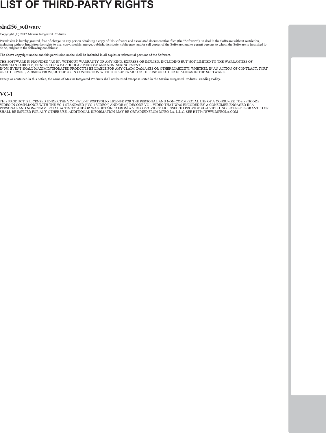
LIST OF 3rd PARTY RIGHTS
ix
x
TABLE OF CONTENTS
INTRODUCTION iii
1
HANDLING PRECAUTIONS 1
2
PRECAUTIONS REGARDING INSTALLATION 4
3 PRECAUTIONS REGARDING OPERATION 7
4 PART DESCRIPTIONS 10
5 ACCESSORIES 11
6 ASSEMBLY AND INSTALLATION 12
6-1 INSTALLING THE CABINET 13
6-2 FIXATION TO SITE 17
6-3 POWER SUPPLY AND OTHER CONNECTIONS 19
6-4 TURNING ON THE POWER 20
6-5 CONFIRMATION OF ASSEMBLY 22
6-6 APPLYING WARNING LABELS (EPILEPTIFORM SEIZURES) 23
7 PRECAUTIONS WHEN MOVING THE MACHINE 24
7-1 PRECAUTIONS WHEN MOVING FROM SITE 25
8 GAME DESCRIPTION 26
8-1 HOW TO PLAY 26
9 EXPLANATION OF TEST AND DATA DISPLAY 33
9-1 SWITCH UNIT AND COIN METER. 34
9-2 SYSTEM TEST MODE 35
9-3 SYSTEM INFORMATION 37
9-4 STORAGE INFORMATION 39
9-5 JVS TEST 41
9-6 MONITOR TEST 44
9-7 SPEAKER TEST 45
9-8 COIN ASSIGNMENTS 46
9-9 CLOCK SETTING 52
9-10 NETWORK SETTING 54
9-11 GAME TEST MENU 58
9-12 BOOKKEEPING 59
9-13 INPUT TEST 64
9-14 OUTPUT TEST 65
9-15 TICKET TEST 66
9-16 GAME ASSIGNMENTS 67
9-17 TICKET SETTINGS 69
9-18 BONUS SETTINGS 70
9-19 DIFFICULTY SETTINGS 71
9-20 BACKUP DATA CLEAR 72
9-21 TICKET ERROR 73

xi
10 CONTROLLER UNIT(S) 74
10-1 REMOVING THE CONTROLLER 75
11 GRAPHICS DISPLAY 78
11-1 SAFETY PRECAUTIONS WHEN HANDLING THE MONITOR 78
12 COIN HANDLING 84
12-1 CLEANING THE COIN SELECTOR 84
12-2 FAULT FINDING 87
12-3 ADJUSTING THE PRICE OF PLAY (EXCEL) 88
13 LAMPS AND LIGHTING 92
13-1 COIN DOOR LAMP 92
13-2 BILLBOARD LED LIGHTING 93
13-3 HALF HOOP LED LIGHTING 95
13-4 FULL HOOP LED LIGHTING 97
14 PERIODIC INSPECTION 99
15 TROUBLESHOOTING 101
15-1
TROUBLESHOOTING (WHEN NO ERROR MESSAGE IS SHOWN) 101
16 GAME BOARD (NuSX) 104
16-1 HANDLING PRECAUTIONS 105
16-2 GAME BOARD (NuSX) - LOCATION 106
16-3 NuSX CLEANING 107
16-4 REPLACING THE LITHIUM BATTERY 108
16-5 NuSX CONNECTIONS 113
16-6 ERROR CODES 114
17 DESIGN RELATED PARTS 123
18 PARTS LIST 124
19 COLOUR CODE TABLE 145
20 SCHEMATIC DIAGRAMS 146
xii
This page intentially left blank
HANDLING PRECAUTIONS
1
1
1
1
HANDLING PRECAUTIONS
When installing or inspecting the machine, be very careful of the following points and pay attention to ensure that
the player can enjoy the game safely.
Non-compliance with the following points or inappropriate handling running counter to the cautionary matters
herein stated can cause personal injury or damage to the machine.
● Proceed with checks and tasks as indicated in these instructions. If instructions
are not followed, or if tasks and/or checks are neglected, an electric shock or
other very serious accident, even fatal accident can occur. Also, customers
could be injured while operation the product.
● Before performing work, be sure to turn the power off. Performing the work with-
out turning the power off can cause an electric shock or short circuit. In cases
where work should be performed in the status of power on, this manual always
states to that effect.
● To avoid an electric shock or short circuit, do not plug in or unplug quickly.
● To avoid an electric shock, do not plug in or unplug with a wet hand.
● Do not expose power cords or earth wires on the surface, (fl oor, passage, etc.)
If exposed, the power cords and earth wires are susceptible to damage. Dam-
aged cords and wires can cause an electric shock or short circuit.
● To avoid causing a fi re or an electric shock, do not put things on or damage
the power cords.
● When or after installing the product, do not unnecessarily pull the power cord. If
damaged, the power cord can cause a fi re or an electric shock.
● In case the power cord is damaged, ask for a replacement through where the
product was purchased from or the offi ce herein stated. Using the cord as is
damaged can cause fi re, an electric shock or leakage.
● Be sure to perform grounding appropriately. Inappropriate grounding can
cause an electric shock.
● Be sure to use fuses meeting the specifi ed rating. Using fuses exceeding the
specifi ed rating can cause a fi re or an electric shock.
● Be sure that connections such as IC BD are made properly. Insuffi cient insertion
can cause an electric shock.
● Specifi cation changes, removal of equipment, conversion and/or addition, not
designated by SEGA are not permitted.
- Failure to observe this may cause a fi re or an electric shock. Non-compliance
with this instruction can have a bad infl uence upon physical conditions of the
players or the onlookers, or result in injury during play.
- SEGA shall not be held responsible for damage, compensation for damage to
a third party, caused by specifi cation changes not designated by SEGA.
● Do not perform any work or change parts not listed in this manual. Doing so
may lead to an accident.
2
HANDLING PRECAUTIONS
1
1
For the IC board circuit inspections, only the use of a logic tester is
recommended. Using a Multi Tester or General Purpose Tester may result in
damage to IC Circuits.
Static electricity from your body may damage some electronics devices
on the IC board. Before handling the IC board, touch a grounded metallic
surface so that the static electricity can be discharged.
This video gaming cabinet utilises a motorised steering feedback system.
Do not attempt to service this part or any other part in close proximity to the
steering mechanism whilst power is applied.
Some parts are not designed and manufactured specifically for this game
machine. The manufacturers may discontinue, or change the specifi cations of
such general-purpose parts. If this is the case, SEGA cannot repair or replace
a failed game machine whether or not a warranty period has expired.
● If you need to perform any work not listed in this manual, request work from the
offi ce indicated in this manual or the point of purchase, or inquires for details.
● Be sure to perform periodic maintenance inspections herein stated.
● Do not touch undesignated places. Touching places not designated can cause
an electric shock or short circuit.
● Whenever any fasteners (e.g. screws, nuts) have been lost, be sure to use re-
placement fasteners with the proper dimensions as specified in this manual.
If fasteners or any other fi xings are used which do not correspond with the di-
mensions as outlined in this manual it may cause damage and/or separation of
parts that may result in secondary accidents.
● When connecting a connector, check the direction carefully. Connectors must
be connected in only one direction. If indiscriminate loads are applied in mak-
ing connections, the connector to its terminal fi xtures could be damaged, re-
sulting in electric shock, short circuit or fi res.
HANDLING PRECAUTIONS
3
1
1
CONCERNING THE STICKER DISPLAY
This SEGA product has stickers attached describing the product manufacture No. (Serial No.) and Electrical
Specifi cations. It also has a Sticker describing where to contact for repair and for purchasing parts.
When inquiring about or asking for repairs, mention the Serial No. and Name of Machine indicated on the Sticker.
The Serial Number indicates the product register. Identical machines could have different parts depending on the
date of production. Also, improvements and modifi cations might have been made after the publication of this
manual. In order to ensure you order the correct parts, mention the Serial No. when contacting the applicable places.
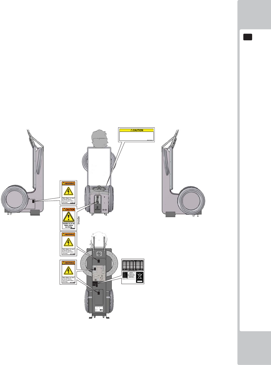
CONCERNING WARNING DISPLAYS
This SEGA product has warning displays on stickers, labels and/or printed instructions adhered/attached to or
incorporated in the places where a potentially hazardous situation could arise. The warning displays are intended
for accident prevention for customers and for avoiding hazardous situations relating to maintenance and servicing
work. Some portions of the cabinet contain high voltage and may cause accidents if touched. When performing
maintenance, be very careful of the warning displays. It is especially important that any complex repair and
replacement work not mentioned herein should be performed by those technical personnel who have knowledge of
electricity and technical expertise.
In order to prevent accidents, caution any customer ignoring the warnings to cease and desist immediately.
If you or your child have experienced a convulsive attack, loss of
consciousness, etc. due to light stimulus or TV games, or fear that you
might experience such symptoms, be very careful of using this
machine.
If you feel sick while playing the game, immediately discontinue use
and take a rest.
4
PRECAUTIONS REGARDING INSTALLATION LOCATION
2
2
2
PRECAUTIONS REGARDING INSTALLATION
• This product is an indoor game machine. Do not install it outside. Even indoors,
avoid installing in places mentioned below so as not to cause a fi re, electric
shock, injury and/or malfunction.
• Places subject to rain or water leakage, or places subject to high humidity in
the proximity of an indoor swimming pool and/or shower, etc.
• Places subject to direct sunlight, or places subject to high temperatures in the
proximity of heating units, etc.
• Places filled with inflammable gas or vicinity of highly inflammable/volatile
chemicals or hazardous matter.
• Dusty places.
• Sloped surfaces.
• Places subject to any type of violent impact.
• Vicinity of anti-disaster facilities such as fi re exits and fi re extinguishers.
• Areas where the temperature exceeds the applicable temperature (ambient
temperature) range of 5 to 30 degrees centigrade.
LIMITATIONS OF USAGE
• Be sure to check the Electrical Specifications. Ensure that this product
is compatible with the location's power supply, voltage, and frequency
requirements. A plate describing Electrical Specifi cations is attached to the
product. Non-compliance with the Electrical Specifi cations can cause a fi re
and electric shock.
• This product requires a breaker and earth mechanism as part of the location
facilities. Using the product without these can cause a fi re and electric shock.
• Ensure that the indoor wiring for the power supply is rated at 15 A or higher
(AC single phase 100 V ~ 120 V area), and 7 A or higher (AC 220 V ~ 240 V
area). Non-compliance with the Electrical Specifi cations can cause a fi re and
electric shock.
• Be sure to use an independent power supply equipped with an earth leakage
breaker. Using a power supply without an earth leakage breaker can cause
an outbreak of fi re if a power surge occurs.
• Putting many loads on one electrical outlet can cause generation of heat and
a fi re resulting from overload.
• When using an extension cord, ensure that the cord is rated at 15 A or higher
(AC 100 V ~ 120 V area) and 7 A or higher (AC 220 V ~ 240 V area). Using a
cord rated lower than the specifi ed rating can cause a fi re and electric shock.
PRECAUTIONS REGARDING INSTALLATION LOCATION
5
2
2
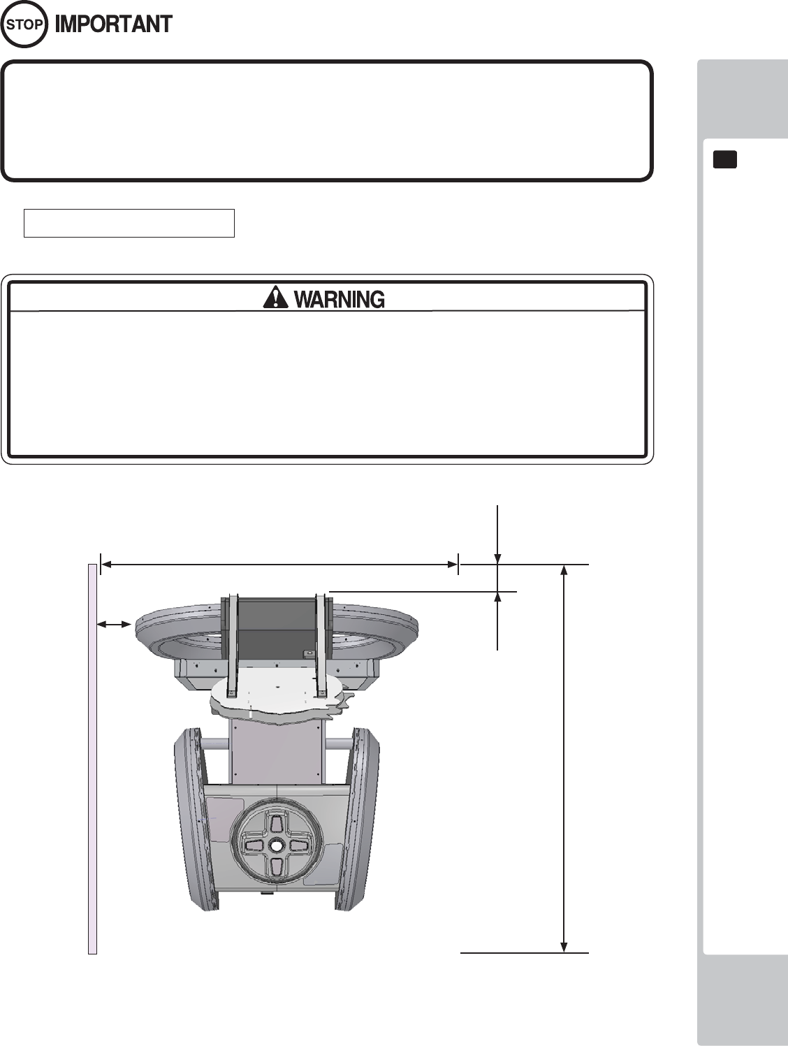
OPERATION AREA
Securing a safe area for operation as described in this manual will ensure
safe operation for players and observers.
SEGA shall not be held responsible for damage or compensation for damage
to a third party, resulting from the failure to observe this instruction.
For the operation of this machine, secure a minimum area of 1.7m (W) x 2.0m (D).
Be sure to provide suffi cient space specifi ed in this manual. Do not allow objects
to block the ventilation ports. It can cause generation of heat and a fi re.
Suffi cient space either side of the playing area must be allowed for the player to
enter or exit the game safely.
1700mm
2000mm
200mm
300mm
6
PRECAUTIONS REGARDING INSTALLATION LOCATION
2
2
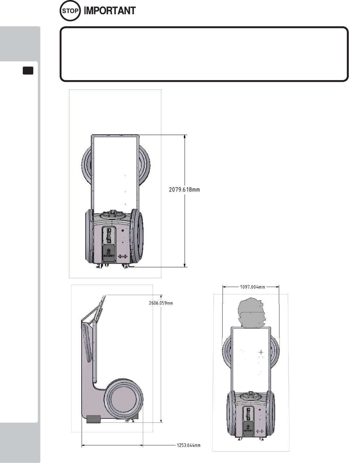
To install this product, the entrance must be at least 1.2m in width and 2.1 m
in height (without Assy Billboard) and 2.7m (with Assy Billboard).
Do not attempt to push/pull whilst holding onto the Assy Billboard. This may
result in part damage and or personal injury.
PRECAUTIONS REGARDING PRODUCT OPERATION
7
3
3
3 PRECAUTIONS REGARDING OPERATION
To avoid injury and trouble, be sure to pay attention to the behavior of visitors and players.
In order to avoid accidents, check the following before starting the operation:
• To ensure maximum safety for the players and the customers, ensure that
where the product is operated has suffi cient lighting to allow any warnings to be
read. Operation under insuffi cient lighting can cause bodily contact with each
other, hitting accident, and/or trouble between customers.
• Be sure to perform appropriate adjustment of the display (LCD, Plasma, CRT
or Projector). For operation of this machine, do not leave monitor's fl ickering or
deviation as is. Failure to observe this can have a bad infl uence upon the players'
or the customers' physical conditions.
• It is suggested to ensure a space allowing the players who feel sick while
playing the game to take a rest.
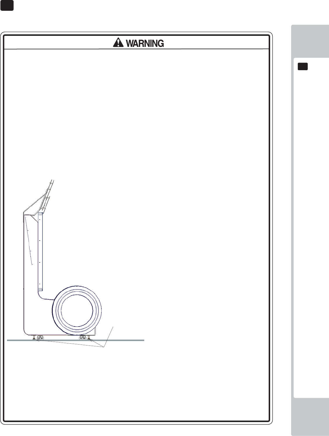
• Check if all of the adjusters are in contact with the surface. If they are not, the
Cabinet can move and cause an accident.
• Do not put any heavy item on this product. Items, if placed on this product
may fall and cause injury to the player / observer.
• Do not climb on the product. Climbing on the product can cause falling down
accidents. To check the top portion of the product, use a step ladder.
Each leg adjuster MUST be lowered so that the
casters are raised approximately 5mm off the
fl oor.
8
PRECAUTIONS REGARDING PRODUCT OPERATION
3
3
It is recommended that wet towels (paper towels) be provided.
• To avoid electric shock, ensure that all covers and panels are undamaged
and fi tted. Do not operate with covers removed.
• To avoid electric shock, short circuit and/or parts damage, do not put the
following items on or in the periphery of the product.
Flower vases, flowerpots, cups, water tanks, cosmetics, and receptacles/
containers/vessels containing chemicals and water.
• To avoid injury, be sure to provide sufficient space by considering the
potentially crowded situation at the installation location. Insufficient installation
space can cause making bodily contact with each other, hitting accidents, and/
or trouble between customers.
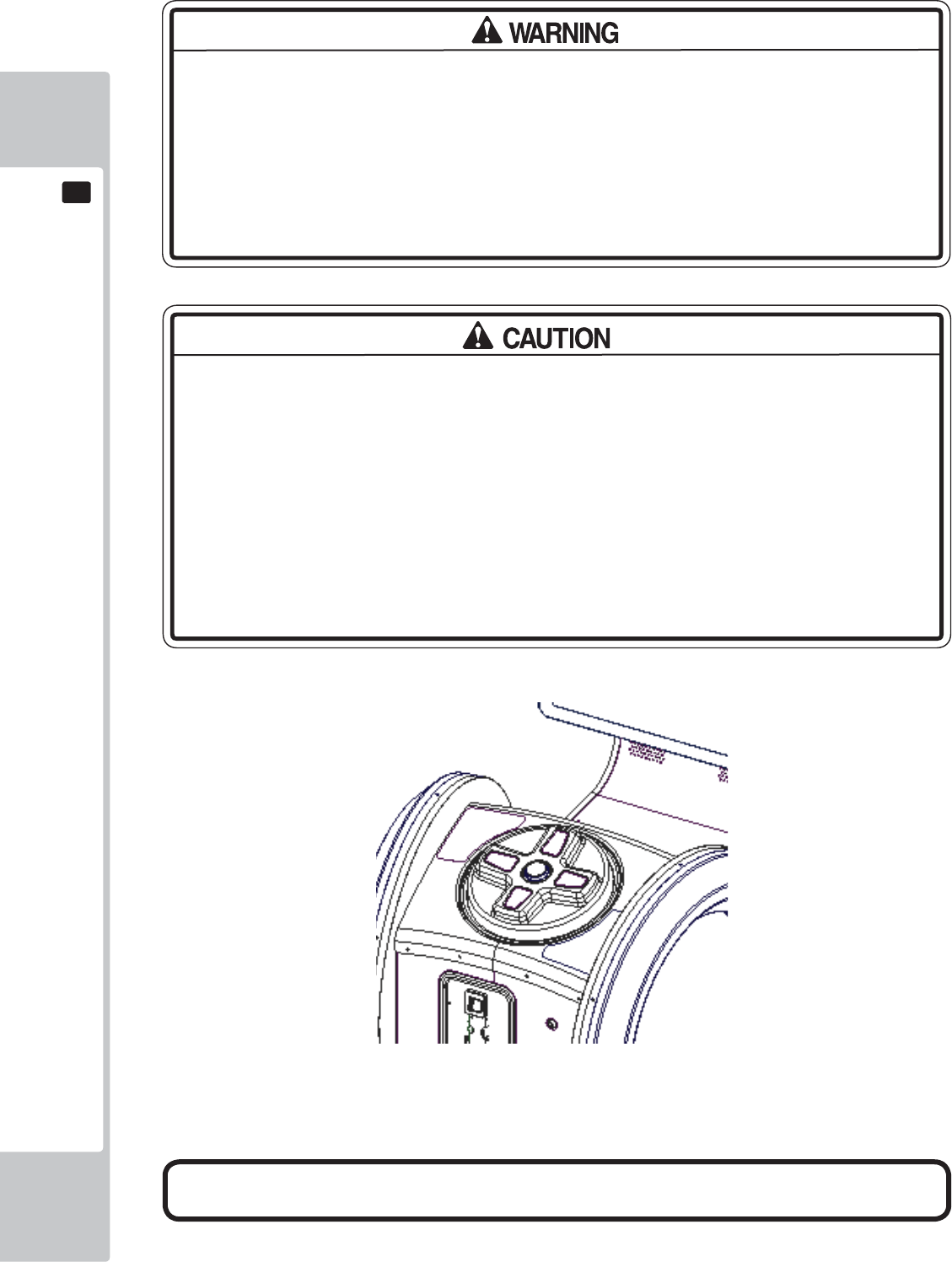
• Everyday when cleaning the Controller, inspect the controller and make sure
that there are no cracks in the surface, and that the fastening screws are not
loose. If the game is played with cracks or loose screws, it can cause injuries to
the player.
• Do not allow more than one person to play the game at any one time.
Frequent checks to the controller for and signs of dmaage or wear and tear.
PRECAUTIONS REGARDING PRODUCT OPERATION
9
3
3
To avoid injury and trouble, be sure to constantly give careful attention to the behavior and manner of the visitors
and players.
• For safety reasons, do not allow any of the following people to play the game.
- Those who have high blood pressure or a heart problem.
- Those who have experienced muscle convulsion or loss of consciousness
when playing video games, etc.
- Those who have neck or spinal cord problems.
- Those who are intoxicated or under the infl uence of drugs.
- Pregnant women.
- Those who are not in good health.
- Those who do not follow the attendant’s instructions.
- Those who cannot grasp the Control Unit securely because of immobility in
fi ngers, hands or arms.
- Persons who disregard the product's warning displays.
• This product is intended for a single player only. Having two or more persons
simultaneously playing this product can result to injury to the player and possible
damage to the product.
• Even players who have never been adversely affected by light stimulus might
experience dizziness or headache depending on their physical condition
when playing the game.
• Small children are especially likely to experience these symptoms. Caution
guardians of small children to keep watch on their children during play.
• Instruct those who feel sick during play to have a medical examination.
• To avoid injury from falls and electric shocks due to spilled drinks, instruct the
player not to place heavy items or drinks on the product.
• To avoid electric shocks and short circuits, do not allow customers to put
hands and fi ngers or extraneous matter in the openings of the product or small
openings in or around the doors.
• To avoid falls and resulting injury, immediately stop the customer from leaning
against or climbing on the product, etc.
• To avoid electric shock and short circuit, do not allow customers to unplug the
power plug without a justifi able reason.
• Instruct the guardians of small children to keep an eye on their children.
• Children cannot sense danger. Allowing small children to get near a player
who is playing the game could result in the children being bumped, struck or
knocked down.
DURING OPERATION (PAYING ATTENTION TO CUSTOMERS)
10
PART DESCRIPTIONS
4
4
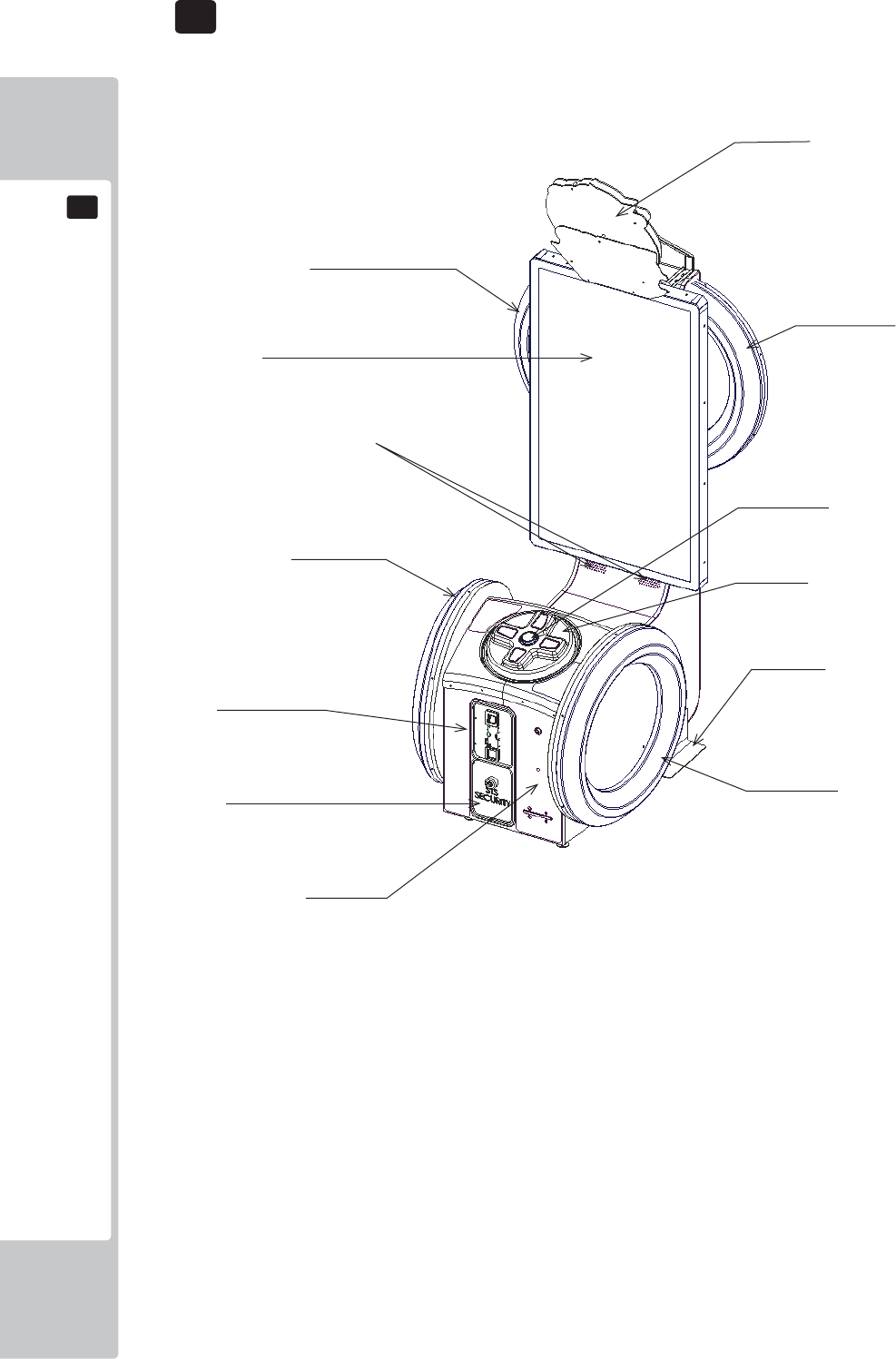
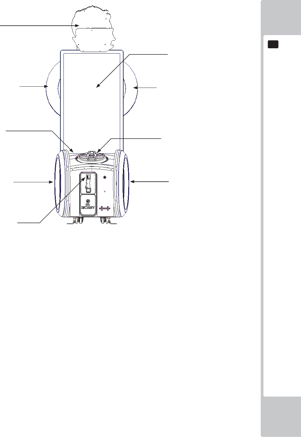
4 PART DESCRIPTIONS
Billboard
Half Hoop L
Half Hoop R
55” LED Screen
Full Hoop L
Speakers
Full Hoop R
STS Secure Door
Ticket Door
Stabilisers
Double Framed Mini
Door (DFMD)
Controller
Dash Button
ACCESSORIES
11
5
5
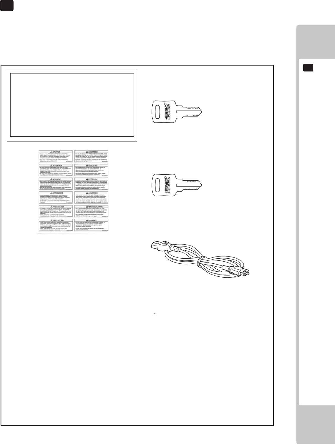
5 ACCESSORIES
Confi rm that the accessories listed in the table below are present when setting up the product.
Accessories marked “Spare” in the note column are consumable items but included as spares.
DESCRIPTION: OWNER’S MANUAL
Part No. (Qty.):
420-0024-01UK(1)
Parts not labeled with part numbers are as yet
unregistered or cannot be registered. Be sure to handle
all parts with care, as some parts are not available for
purchase separately.
KEY MASTER
220-5575-01UK (2)
For operating/closing the doors
KEY
(2)
For the cashbox door
(Located inside the coin chute door at time of
shipment)
POWER CORD
LM1227 (1) <UK>
LM1226 (1) <EU>
For installation. See chapter 6.
440-CS0186UK
Sticker C Epilepsy Multi (1)
12
ASSEMBLY AND INSTALLATION
6
6
6 ASSEMBLY AND INSTALLATION
• Perform assembly work by following the procedure herein stated. Failure to
comply with the instructions can cause electric shock.
• Perform assembly as per this manual. Since this is a complex machine,
incorrect assembling can cause an electric shock, machine damage and/or
improper functioning as per specifi ed performance.
• When assembling, more than one person is required. Depending on the
assembly work, there are some cases in which working by one person alone
can cause personal injury or parts damage.
• Ensure that connectors are properly connected. Improper connections can
cause electric shock.
• Be careful not to damage the wires. Damaged wires may cause electric shock
or short circuit or present a risk of fi re.
• Do not unnecessarily push the display screen.
• This work should be carried out by site maintenance personnel or other
qualifi ed professionals. Work performed by non-technical personnel can cause
a severe accident such as electric shock. Failing to comply with this instruction
can cause a severe accident such as electric shock to the player during
operation. If no one with proper technological expertise is available, request
service from the offi ce indicated in this document or the point of purchase so
as to ensure safety.
• Provide suffi cient space so that assembling can be performed. Performing
work in places with narrow space or low ceiling may cause an accident and
assembly work to be diffi cult.
• To perform work safely and avoid serious accident such as the cabinet falling
down, do not perform work in places where step-like grade differences, a
ditch, or slope exist.
• This product does not use any connectors other than those connected to and
used by the game board when it leaves the factory. Do not needlessly connect
wires to unused connectors. This could lead to overheating, generation of
smoke and burn related injuries.
• Handle molded parts with care. Excessive weight or pressure may cause them
to break and the broken pieces may cause injury.
• To perform the operation safely and accurately you must use a safe, steady
footstool or stepladder. Working without this may lead to a fall and possible
injury.
ASSEMBLY AND INSTALLATION
13
6
6
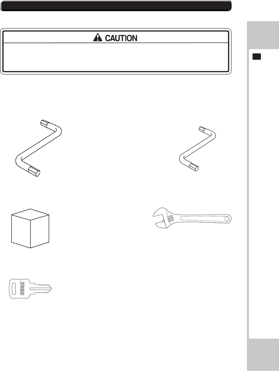
Tools required for installation:
• To perform work safely and securely, be sure to prepare a step which is in a
safe and stable condition. Performing work without using a step may lead to
injury of damage to components.
Allen Key (M8) (Not Supplied)
- Attaching ASSY BILLBOARD to cabinet
- Attaching BKT CABI LOWER
Allen Key (M4) (Not Supplied)
- Attaching ASSY Billboard to cabinet
Step or Ladders
- Aid in fi xing Billboard and Billboard Panel.
Adjustable Wrench
- Secure cabinet into position.
KEY
- Gain access to Coin Tower
6-1 INSTALLING THE CABINET
14
ASSEMBLY AND INSTALLATION
6
6
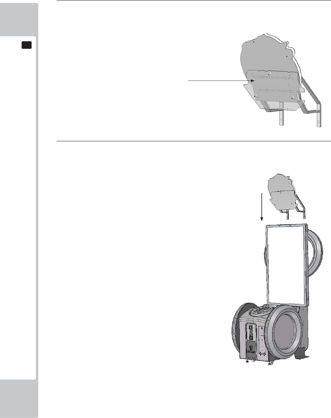
1
The Billboard is separately wrapped along with the cabinet and needs to be applied prior install..
2
Using a Step Ladder or Stool, raise the ASSY BILLBOARD and align with the fi xing holes at the top of the
cabinet.
6-1-1 INSTALLING THE ASSY BILLBOARD
Assy Billboard - SND 0500UK
ASSEMBLY AND INSTALLATION
15
6
6
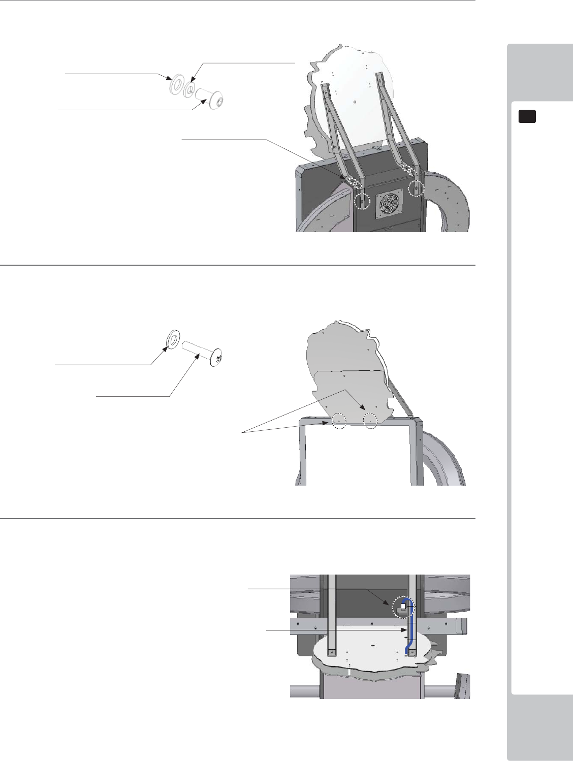
3
Once in position, secure the ASSY BILLBOARD at the rear of the cabinet using (6) M8x25 SKT CAP
Screws and washers (029-B00825-0B/060-S00800-0B/068-852216-0B)
4
Fit and secure the remaining 2 fi xings at the front of the ASSY BILLBOARD using (2) M4x12 SKT CAP
Screws and washers.
5
Once the ASSY BILLBOARD is secure, make the connection to the cabinet where shown.
Make sure that there are no trailing cables. Any loose cables must be secure to the ASSY BILLBOARD
brackets.
x6
x2
Fixing locations
M8x20 Socket Cap Screws
029-B00825-0B
M4 WSHR 16OD FLT BLK
068-441614-0B
M4x12 SKT BH BLK
029-B00412-0B
ASSY BILLBOARD lighting harness
M8 WSHR 22OD FLT BLK
068-852216-0B
M8 WSHR SPR BLK
060-S00800-0B
Fixing Points
Conection Point
16
ASSEMBLY AND INSTALLATION
6
6
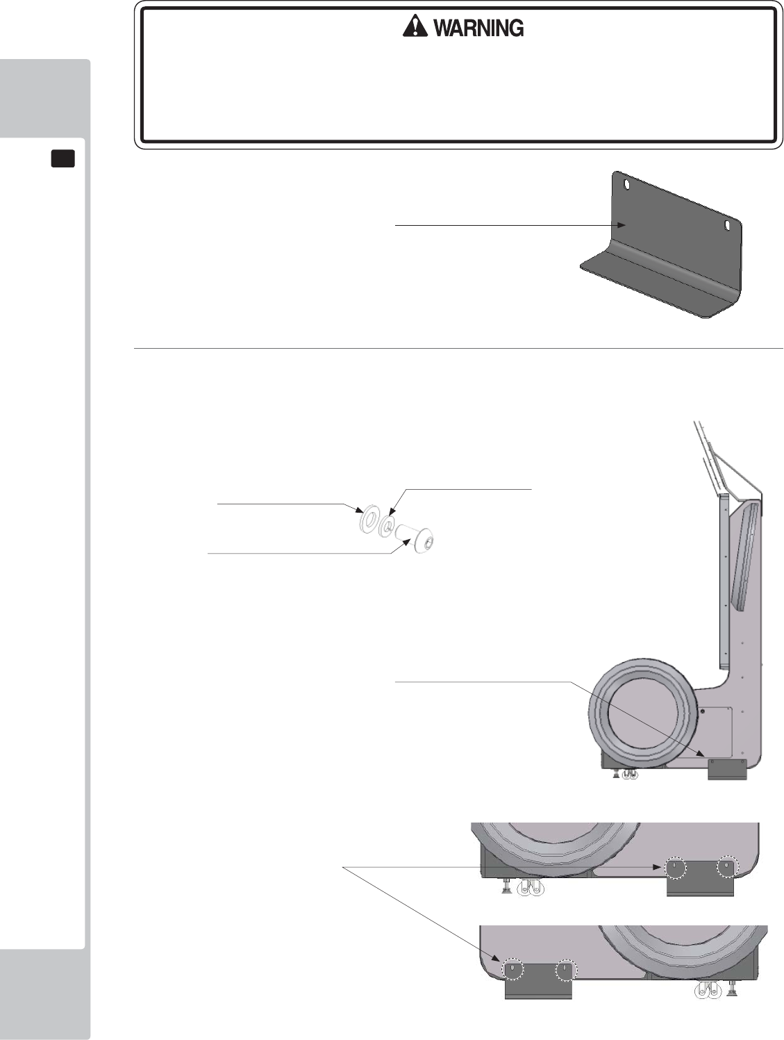
6
Apply the BKT CABI LOWER to both side of the cabinet as shown. Secure using (4) M8x25 SKT CAP
Screws and washers (029-B00825-0B/060-S00800-0B/068-852216-0B)
Fixing Points
BKT CABI LOWER (2)
PD-1002UK
BKT CABI LOWER (2)
PD-1002UK
• Due the nature and the design of the cabinet it is IMPORTANT that the CABINET
LOWER BRACKETS are fi tted to both sides of the cabinet. These brackets, when
fi tted provide the cabinet with extra stability. Failing to apply these brackets to
the cabinet may render the cabinet unstable.
x4
M8x20 Socket Cap Screws
029-B00825-0B
M8 WSHR 22OD FLT BLK
068-852216-0B
M8 WSHR SPR BLK
060-S00800-0B
ASSEMBLY AND INSTALLATION
17
6
6
• Make sure that all the adjusters contact the fl oor. Otherwise the cabinet could
move, causing an accident.
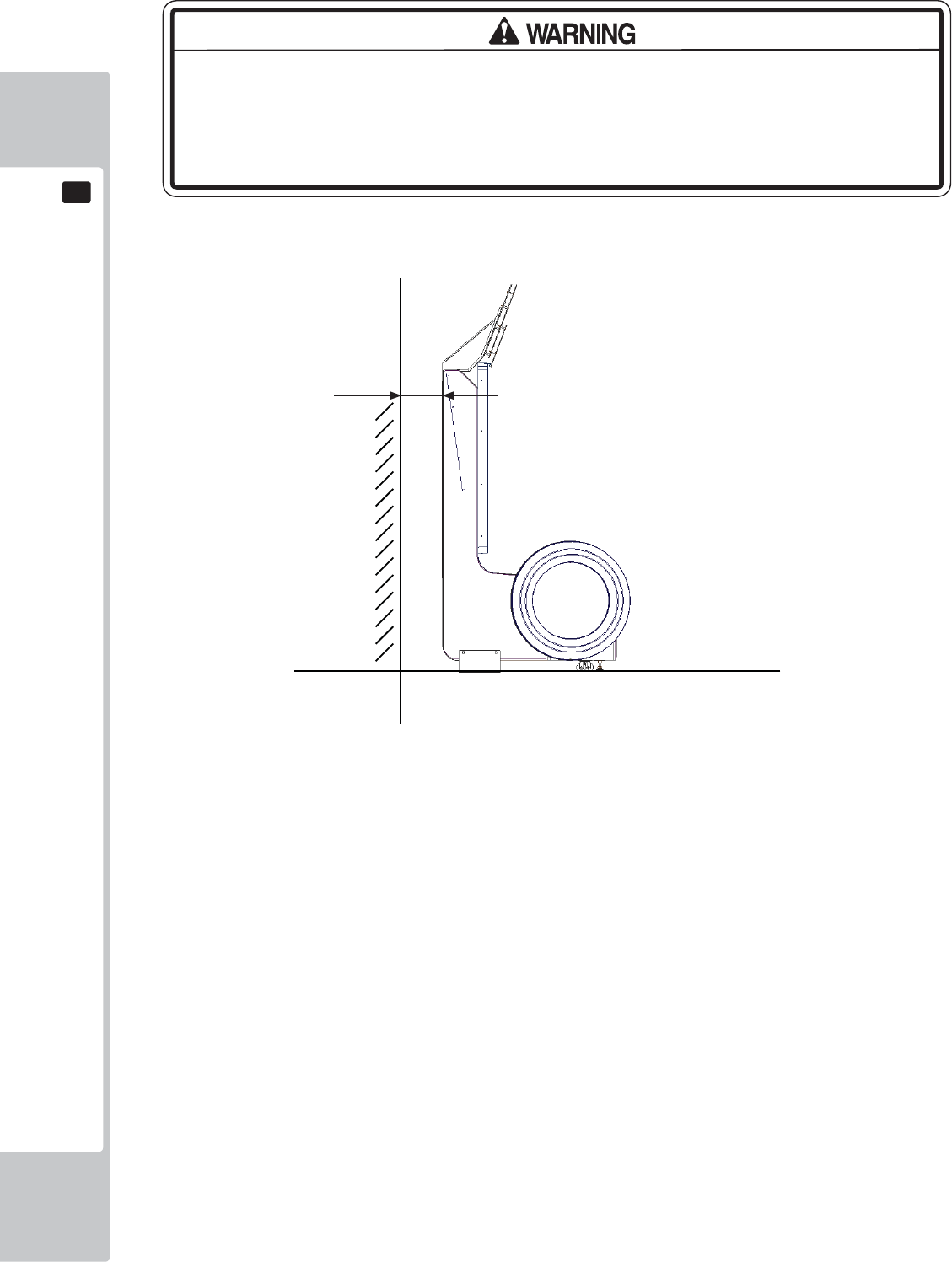
• Provide a ventilation space at least 20cm wide behind the cabinet. There are
ventilation holes on the back of the cabinet. Do not block the ventilation holes.
Doing so could trap heat inside resulting in fi re. It could also result in equipment
damage or cause parts to become exhausted prematurely.
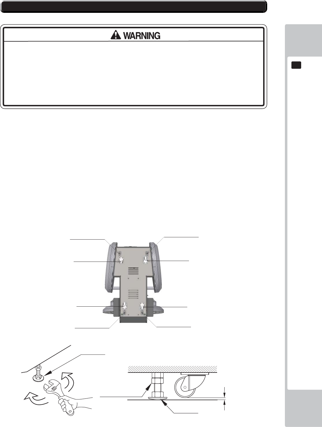
The product is equipped with 4 casters and 4 adjusters.
When installation position / site has been determined, have the adjusters come in direct contact with the floor.
Establish a gap of about 5 mm between the fl oor and the casters and adjust the unit so that it will remain level.
1 Move the product to the installation site.
2 Bring the adjusters into direct contact with the fl oor. Use a wrench to align the height of the adjusters until the
cabinet is perfectly level.
3 After setting, turn adjuster nuts upwards to tighten them and secure adjuster heights.
Approx. 5 mm
ADJUSTER
Fasten the nuts in an
upward direction.
ADJUSTER
CASTER
6-2 FIXATION TO SITE
/(*$'-867(5 /(*$'-867(5
/(*$'-867(5 /(*$'-867(5
&DVWRU
&DVWRU
&DVWRU
&DVWRU
18
ASSEMBLY AND INSTALLATION
6
6
200mm
• Provide a ventilation space at least 20cm wide behind the cabinet. There are
ventilation holes on the back of the cabinet. Do not block the ventilation holes.
Doing so could trap heat inside resulting in fi re. It could also result in equipment
damage or cause parts to become exhausted prematurely.
Leave a 200mm gap for ventilation
ASSEMBLY AND INSTALLATION
19
6
6
• Use the power supply equipped with an earth leakage breaker. Use of power
supply without such a breaker could result in fi re if there is a current leakage.
• Have available a securely grounded indoor ground terminal. Without proper
grounding, customers could be electrocuted and product operations might not
always be stable.
• Do not expose the power cord or ground wire. If these are exposed, customers
could stumble over them, for instance, and easily damage them. Additionally, if
these lines are damaged, there could be a risk of electrical shock or short circuit.
Set these lines at locations where they will not interfere with customer traffi c, or
attach covers to them.
• After laying out the power cord on the floor, be sure to always protect it. If
the power cord is left exposed, it can easily be damaged, resulting in electrical
shock.
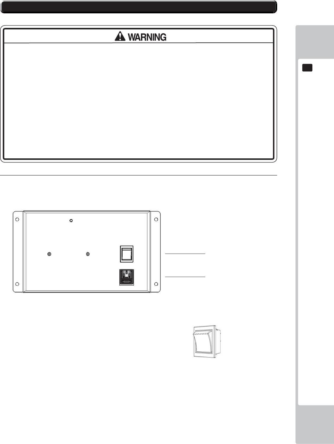
1
Confi rm that the main switch is at OFF.
Mains Switch shown in
OFF position
Mains ON/OFF Switch
IEC Inlet
6-3 POWER SUPPLY AND OTHER CONNECTIONS
USE ONLY 250V FUSES
20
ASSEMBLY AND INSTALLATION
6
6
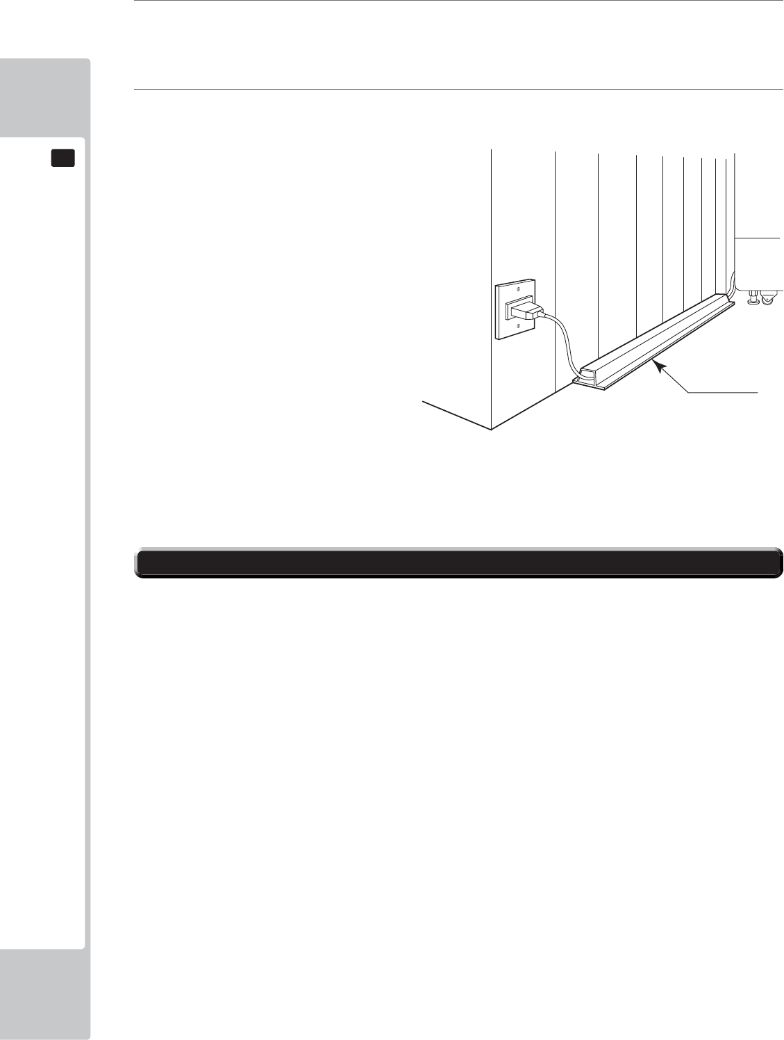
2
Fully insert the power cord connector on the side opposite the power plug into the AC unit IEC inlet. Insert
the power cord plug into the outlet.
3
The power code is laid out indoors. Protect the power cord by attaching wire cover to it.
WIRE COVER
Set the main switch of the AC unit to ON and engage the power.
When you turn on the power, the billboard LED lights will come on.
After the SEGA LOGO start up screen is displayed on the LCD screen, the Advertise (Attract) Mode will
start.
The decorative LEDs within the FULL and HALF HOOPS will scroll through a variation of colours.
Start up sounds are output from the speakers on the left and right of the cabinet together with display of the
SEGA startup screen.
Even when the power source has been cut off, credit count, ranking data, game settings and bookkeeping
data are kept stored in the product. However, fractional coin counts (inserted coins that do not amount to one
credit) and bonus adder counts are not kept.
6-4 TURNING ON THE POWER
ASSEMBLY AND INSTALLATION
21
6
6
Attract Mode - Game
COMPONENTS WHICH CHANGE STATE WHEN POWER IS APPLIED
Billboard illumination
Audio output
SEGA logo
Half Hoop Illumination
Full Hoop Illumination
Half Hoop Illumination
Full Hoop Illumination
Coin Door Lamp
Controller Illumination

22
ASSEMBLY AND INSTALLATION
6
6
In the test mode, ascertain that the assembly has been made correctly and IC Board is satisfactory.
In the test mode, perform the following test: (refer to chapter 9).
9-13 INPUT TEST
This menu is used to test the system inputs such as steering, pedals and buttons. To implement the test, press each
device that is listed and check the results on screen.
9-14 OUTPUT TEST
This menu is used to test the system oututs such as Lamps and LED.
9-8 COIN ASSINMENTS
As this system utilises a Credit Board PCB, it is important that the setting remain 1 COIN 1 PLAY. Deveation from
this setting when using the Credit Board PCB can result in unusual credit outputs.
9-15 TICKET TEST
This menu will allow you to check the output of tickets. (Not required in Amusement Only Mode)
9-16 GAME ASSIGNMENTS
This test is required to confi gure the game according to its location.
6-5 CONFIRMATION OF ASSEMBLY
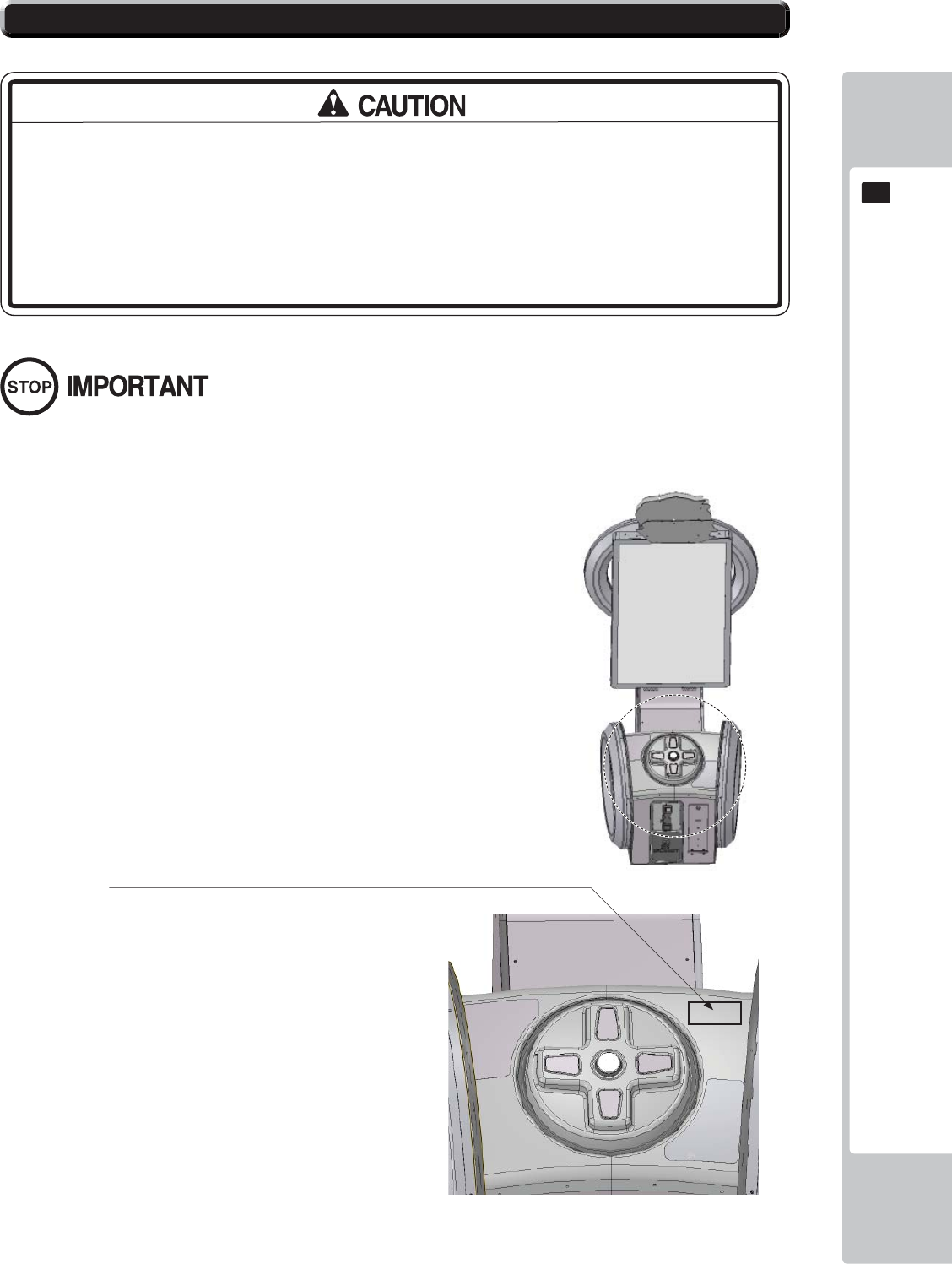
ASSEMBLY AND INSTALLATION
23
6
6
• The operator MUST apply the Epileptiform Seizure Label to this product.
Failing to apply this label may result in the player/observer suffering from a
photosensitive seizure. Warning the potential player/ observer of this before
the start of a game may prevent such accidents.
• It is also important to apply the correct language label for each location. There
are nine (9) different language labels - please apply the label which matches
your location. (ENGLISH is fi tted by default).
Application of any warning labels must be placed in a location which is easy for the player/observer to read.
Please follow the instructions below and apply the label in the location stated.
The Epileptiform Seizure label is supplied in 9 different languages.
Please choose the label which matches your language location.
Apply the label to the top right hand corner of the Control Panel.
This location is unobstructed and can be easily read by players and
observers alike.
6-6 APPLYING WARNING LABELS (EPILEPTIFORM SEIZURES)
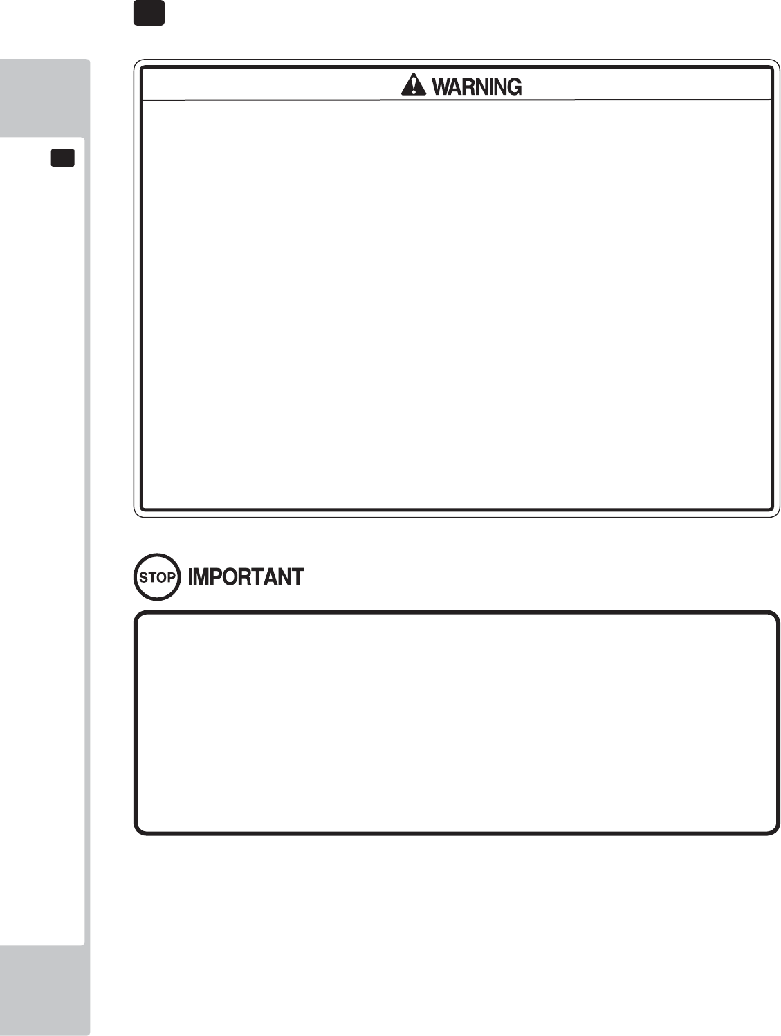
24
PRECAUTIONS WHEN MOVING THE MACHINE
7
7
7 PRECAUTIONS WHEN MOVING THE MACHINE
• When moving the cabinet, do not grip or push the Billboard Plate. Doing so
could deform or damage the part.
• When moving the cabinet, do not grip or push the HOOPS. Doing so could
deform or damage the part.
• When moving the cabinet, do not grip or push the Controller. Doing so could
deform or damage the part.
• If moving through a door or place with a low ceiling such as an elevator, you
should take apart the billboard and billboard plate.
• Always disconnect the power cable before moving the product. If it is moved
with the power cable connected, the cable could be damaged, causing fi re
or electric shock.
• To move the unit over the floor, pull in the adjustors and have the casters
contact the floor. Remove the CABINET LOWER BRACKETS. While moving the
unit, be careful that the casters do not roll over the power cord or the ground
wire. If cord or wire is damaged, there could be electrical shocks and/or short
circuits.
• When crossing a sloped or stepped area, always have the machine travel
lengthways with the screen towards the slope. Travelling with the machine
in a sideways position could result in the machine falling over onto its side.
Always use a minimum of two people working together plus lifting apparatus
to accommodate slopped areas or stairs.
• To lift up the cabinet, hold it at the bottom at the designated lifting points. If you
hold it anywhere else, the weight of the cabinet could cause damage to parts
or attachments, resulting in injury.
• Do not push the cabinet from the side when moving. Pushing from the side as it
may result in the cabinet falling over.
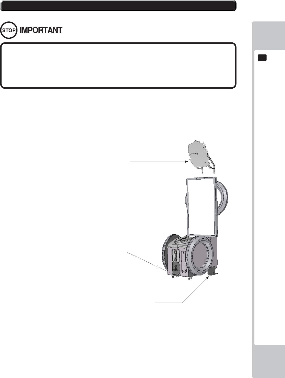
PRECAUTIONS WHEN MOVING THE MACHINE
25
7
7
• When moving the cabinet, do not grip or push the Billboard Plate. Doing so
could deform or damage the part.
• If moving through a door or place with a low ceiling such as an elevator, you
should take apart the billboard and billboard plate.
Detailed instructions for removing the Assy Billboard and Billboard Plate can be found in Chapter 6 of this manual.
Please follow these instruction in reverse order for removal.
7-1 PRECAUTIONS WHEN MOVING FROM SITE
Ensure that the casters come
into contact with the fl oor before
moving.
Remove the Lower Stability
Brackets when moving over
greater distances.
Remove the Billboard and Billboard Plate
when transporting the machine in and out
of buildings or when passing through areas
with low ceilings.
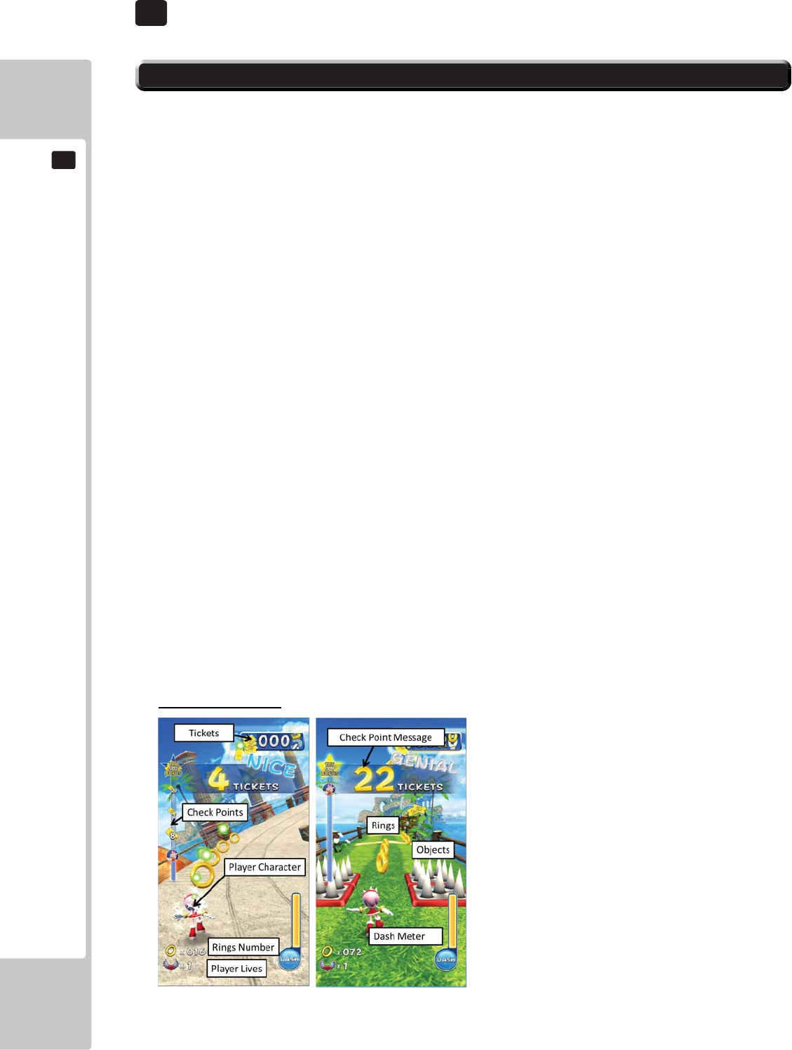
26
GAME DESCRIPTION
8
8
8 GAME DESCRIPTION
8-1 HOW TO PLAY
GAME INTRODUCTION
This machine has two game modes. One is “Ticket Redemption, the other is “Amusement only” (Fun for
play, no tickets).
(Redemption /Amusement mode)
1. After the coins are inserted, available credits will display at the bottom of the screen.
2. After required coins are inserted, the text will change from “Please insert coins” into “Please press
start button”. The start button on the cabin will be fl ickering.
3. Coin system can accumulate up to 24 credits. Credits beyond 24 will not be counted and not
returned to player, but will be recorded by system internal counter.
4. “INSERT COIN(S)”/”INSERT MORE COIN(S)” may change to “SWIPE CARD TO PLAY”. Based on
the difference of test mode settings,
*If you set mode setting “AUTO START ON” , Players can immediately play this game without pressing
start button when credits are available to play.
GAME SCREEN
Below shows each game screen mode of redemption mode and arcade mode.
Redemption mode
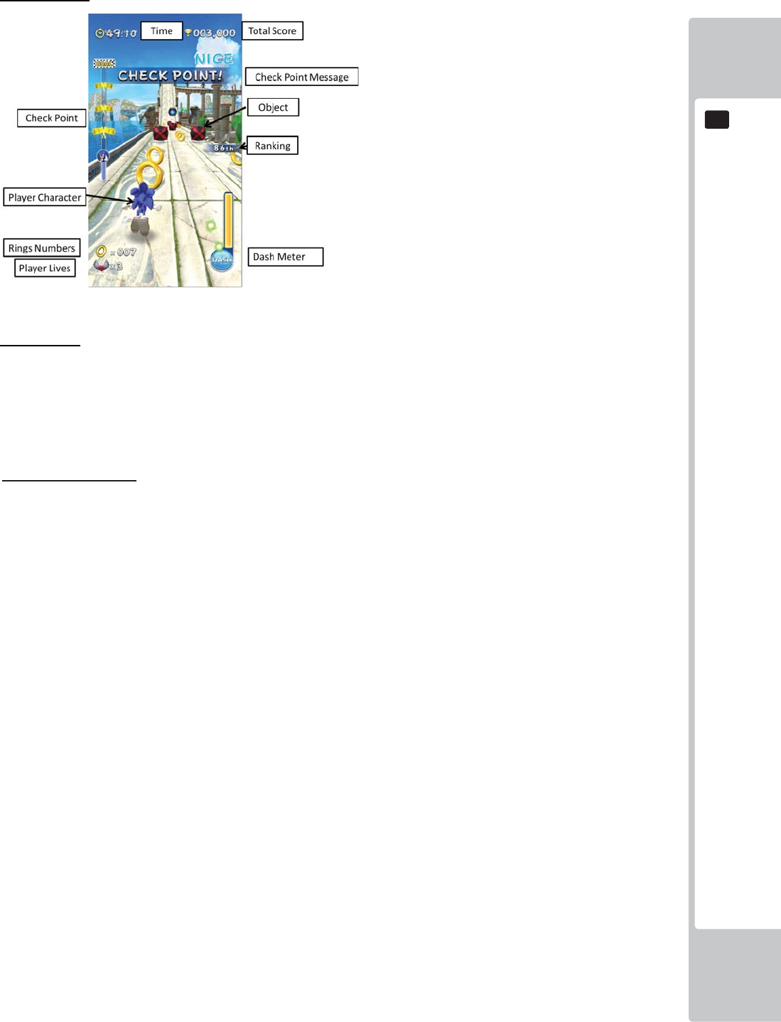
GAME DESCRIPTION
27
8
8
Arcade mode
Basic Rules
Player’s target is to reach goal. For that, some actions are required.
Redemption/Arcade
1. Player’s character has limited lives for playing game. *
2. Character automatically go forward when this game starts
3. Reach to the goal area by controlling the character.
4. Player character will encounter diffi culties like objects and creatures on the route.
5. Otherwise, There are some items that support character.
6. Character’s lives are reduced when player fails to avoid certain objects or hit against creatures
without accumulating rings.
7. Game is over when there is no left lives.
*Under the redemption mode, life is fi xed as one.

28
GAME DESCRIPTION
8
8
Basic Control
Take action with D-pad and button not only for avoiding crashing but also attacking the creatures.
1. Player can use a D-Pad and a Dash button for some action.
2. Each direction on D-Pad means take action like below.
Up:Jump
Left:Move to Left
Right:Move to Right
Down:Rolling(Lower position and attack with rolling)
3. Character can dash with pressing start/dash button when dash meter is fully charged. Dash
means not only does the character speed up but also protected from any trouble.
Rings, Items, Objects
- Rings
・Dash meter will increase when your character collects rings. When the Dash meter is full, Player
can make their character Dash using the DASH ACTION button.
- Items
・There are items on route. For instance, bonus rings which help in protecting your character etc.
- Objects
• There are some structures made by wood, stones on the route.
• Players can avoid crashing into these with using D-pad/Dash.
• If a character crashes into an object, the character lives will be reduced.
- Creatures
• A Player can avoid or beat creatures when Rolling or by pressing the DASH button.
• When character crash into creatures, the character will lose all their rings. If a character crashes
with creatures without rings, the character lives will be reduced.
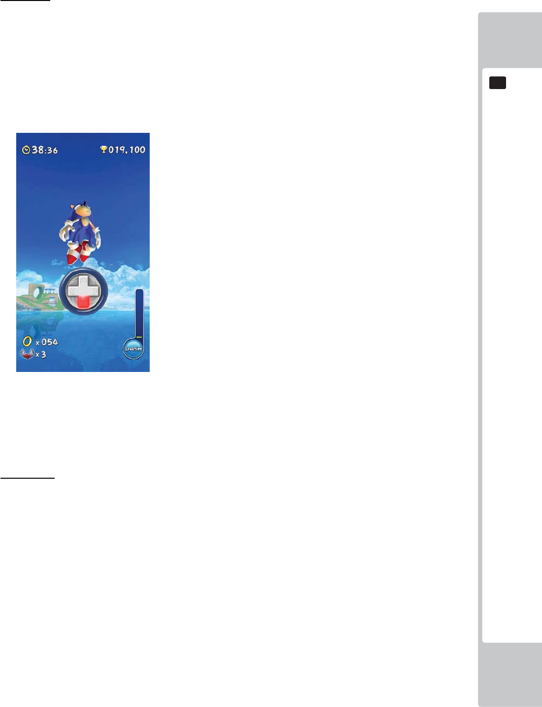
GAME DESCRIPTION
29
8
8
Mini Game
・As the game continues, There is an area where the character automatically jump to sky.
・This is called a “Mini Game” where "ACTION!” will take place.
・A players have to turn D-Pad directions on screen information within limited time.
・If the player succeed in action, he/she can gain extra score bonus.
・If the player fail in action, he/she can’t gain it.
[ACTION! screen]
Boss Battle
At the end of the level, there will be an Eggman boss to fi ght against. Just like in mini game, a
player needs to turn D-Pad directions or press the button on screen information.
If the player succeed in action, BOSS life gauge will decrease. When the BOSS life gauge decreas-
es to 0, it is defeated.
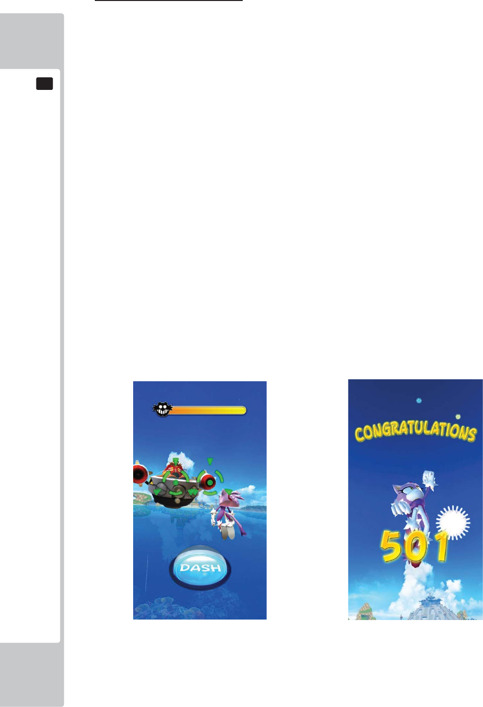
30
GAME DESCRIPTION
8
8
Summary of Redemption mode.
- Flow
1. A player will select his/her character.*
2. After character selected, each stage will automatically be selected.
*If you set mode setting “SKIP SELECT SEQUENCE ON”, a player character is automatically
selected.
3.Game starts
4. The Player can get tickets with going through check points and collecting rings.
5. The Player can collect tickets when reaching each Checkpoint or the Goal.
6. The player can also get bonus ticket when he/she collects rings.
- Mini Game
• As the game plays along, mini game sequence will start. The player has to turn D-Pad directions
and follow on-screen information.
- Boss Battle(Super Bonus)
• If you set “SUPER BONUS ON” on the test mode, Boss battle sequence will start after player
pass through the goal. The player can get super bonus if he/she defeats the boss.
• Boss battle is a timing game which involves pressing the DASH button.
[Redemption mode: Boss Battle] [Redemption mode: Super Bonus]
Closing credits - When a player completes the super bonus, Closing credits will show on screen.
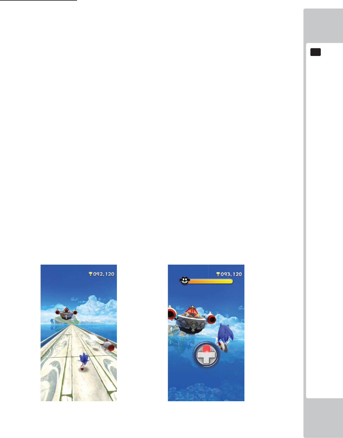
GAME DESCRIPTION
31
8
8
Summary of Arcade mode.
- Flow
1. A player will select his/her character.*
2. After a character is selected, the player will choose a diffi culty and stage.
3. Game starts
4. This mode has time limits. If time is over, it means game over.
5. Amusement mode has various scores for different skills of players.
6. Daily top 10 high score rank will show on attract mode.
- Mini Game
•
As game plays along, mini game sequence will start. The player has to turn D-Pad directions on
screen information.
- Boss Battle
• If a player reaches the goal point, the Boss Battle will start.* Player can get good score by the
beating boss.
• Boss Battle has only one chance. If player misses, Game will be over.
・Amusement Boss Battle has two sequence.
1. Missile Battle - Objective is to avoid the missiles which Eggman fi res
2. Action Battle - It has 3 time battle. The fi rst and second battle as same as mini game(D-
pad), but the last 3rd battle is timing action as same as redemption boss battle.
[Boss Battle 1 Missile Battle] [Boss Battle 2 Action Battle]
If a player defeat Eggman, he/she can gain bonus scores.

32
GAME DESCRIPTION
8
8
Ranking
Amusement mode has daily ranking system. Players can join a daily top 10 ranking where he/she can
enter his/her name within 3 characters.
[Name entry]
-Closing credits
If a player defeats Eggman and also gain the top score of the day, closing credit will show on the screen.
EXPLANATION OF TEST AND DATA DISPLAY
33
9
9
9 EXPLANATION OF TEST AND DATA DISPLAY
Perform tests and data checks periodically by manipulating the TEST Button and SERVICE Button in the cabinet.
Follow the instructions in this chapter to conduct checks when the game machine is fi rst installed, when money is
being collected, or when the game machine does not operate properly.
Shown overleaf are the tests and screens to be used for different problems.
• When installing 2 of more cabinets which are networked together. The GAME
SETTINGS which are adjusted within the fi rst cabinet are refl ected throughout all
cabinets within that network.
• When changing the game confi guration within the TEST MODE, be sure to exit
all screens in the correct manner by choosing exit. DO NOT turn the machine
ON/OFF to resume game. Changes WILL NOT take effect unless the correct
method is used.
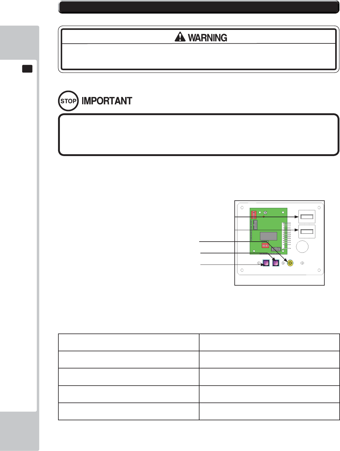
34
EXPLANATION OF TEST AND DATA DISPLAY
9
9
9-1-1 SWITCH UNIT
Open the coin chute door, and the switch unit shown will appear.
The functioning of each SW is as follows:
TEST Button (TEST): For the handling of the Test Button, refer to the
following pages.
SERVICE Button (SERVICE): Gives credits without registering on the coin meter.
Sound Volume Switch (SOUND VOLUME): Adjust sound volume for all of the machines’ speakers.
Coin Counter Counts and displayes coins in $0.10 units.
Game Counter Counts games played
• Adjust the sound to the optimum volume, taking into consideration the
environmental requirements of the installation location.
• Removing the Coin Meter circuitry renders the game inoperable.
9-1 SWITCH UNIT AND COIN METER.
Never touch places other than those specifi ed. Touching places not specifi ed can
cause electric shock and short circuit accidents.
9-1-1 FIG. 01
Volume Control
Service Button
Test Button
Game Counter (not used)
Coin Counter
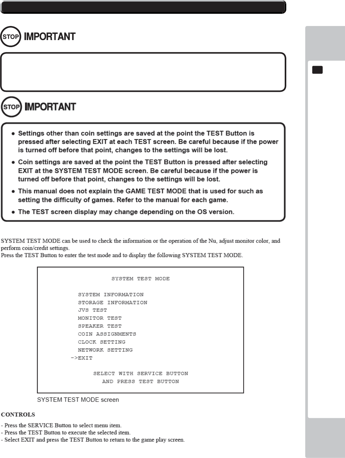
EXPLANATION OF TEST AND DATA DISPLAY
35
9
9
9-2 SYSTEM TEST MODE
The details of changes to Test Mode settings are saved when you exit from each
Test Mode by selecting EXIT. Be careful because if the power is turned off before
that point, changes to the settings will be lost.
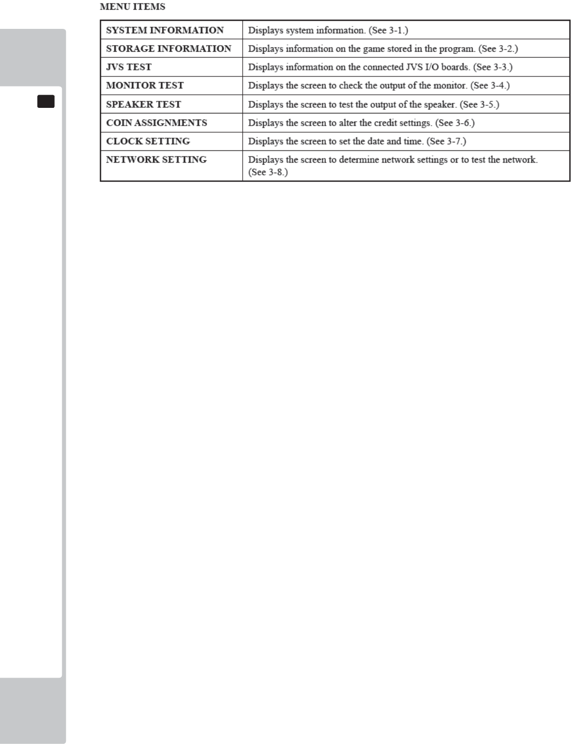
36
EXPLANATION OF TEST AND DATA DISPLAY
9
9
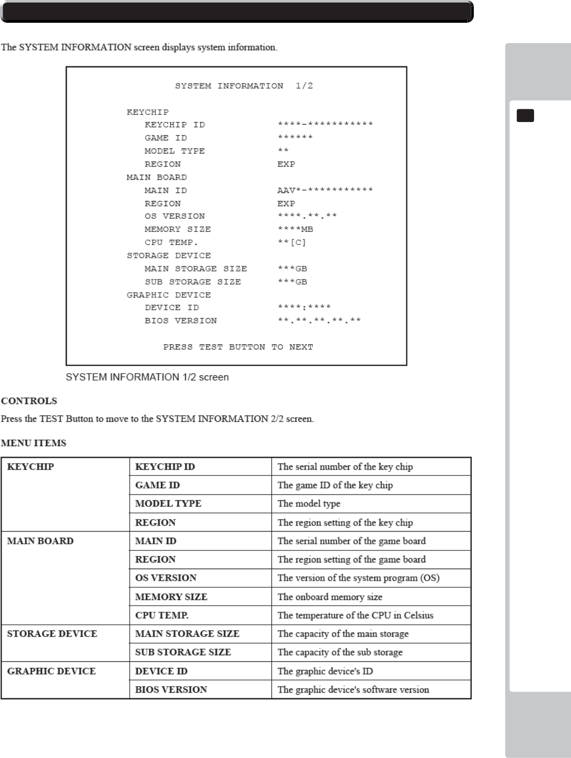
EXPLANATION OF TEST AND DATA DISPLAY
37
9
9
9-3 SYSTEM INFORMATION
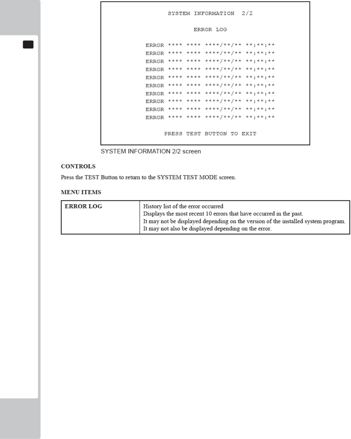
38
EXPLANATION OF TEST AND DATA DISPLAY
9
9
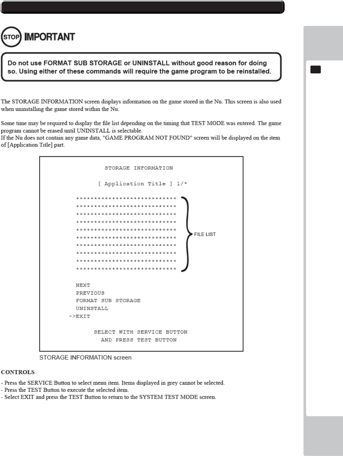
EXPLANATION OF TEST AND DATA DISPLAY
39
9
9
9-4 STORAGE INFORMATION
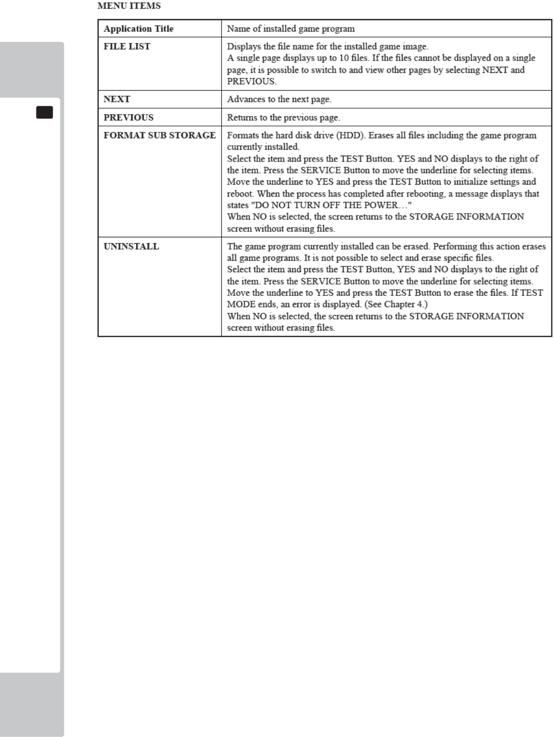
40
EXPLANATION OF TEST AND DATA DISPLAY
9
9
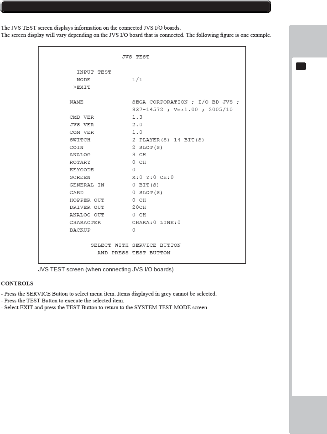
EXPLANATION OF TEST AND DATA DISPLAY
41
9
9
9-5 JVS TEST
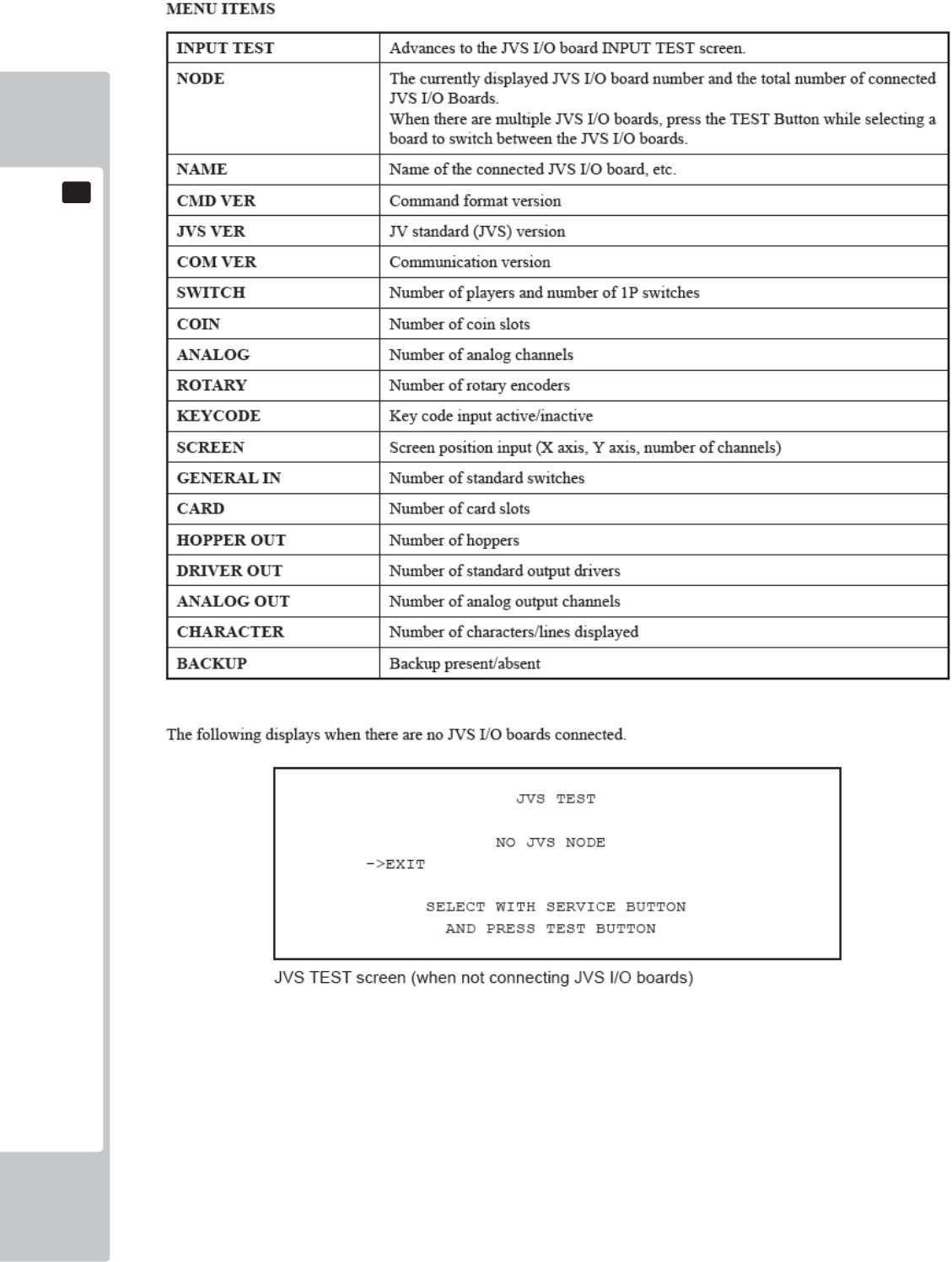
42
EXPLANATION OF TEST AND DATA DISPLAY
9
9
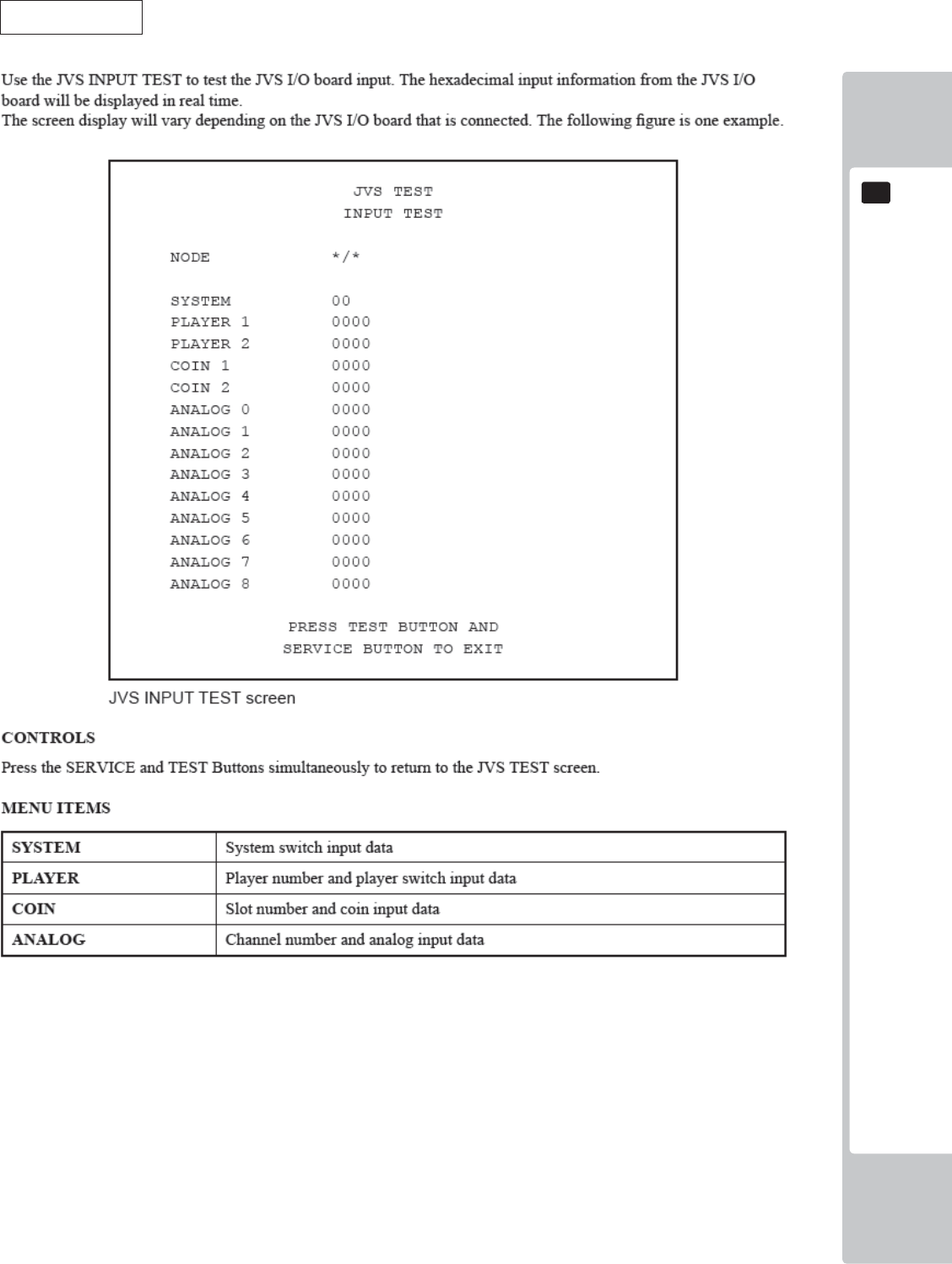
EXPLANATION OF TEST AND DATA DISPLAY
43
9
9
JVS INPUT TEST
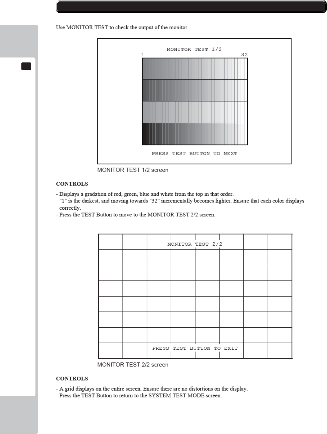
44
EXPLANATION OF TEST AND DATA DISPLAY
9
9
9-6 MONITOR TEST
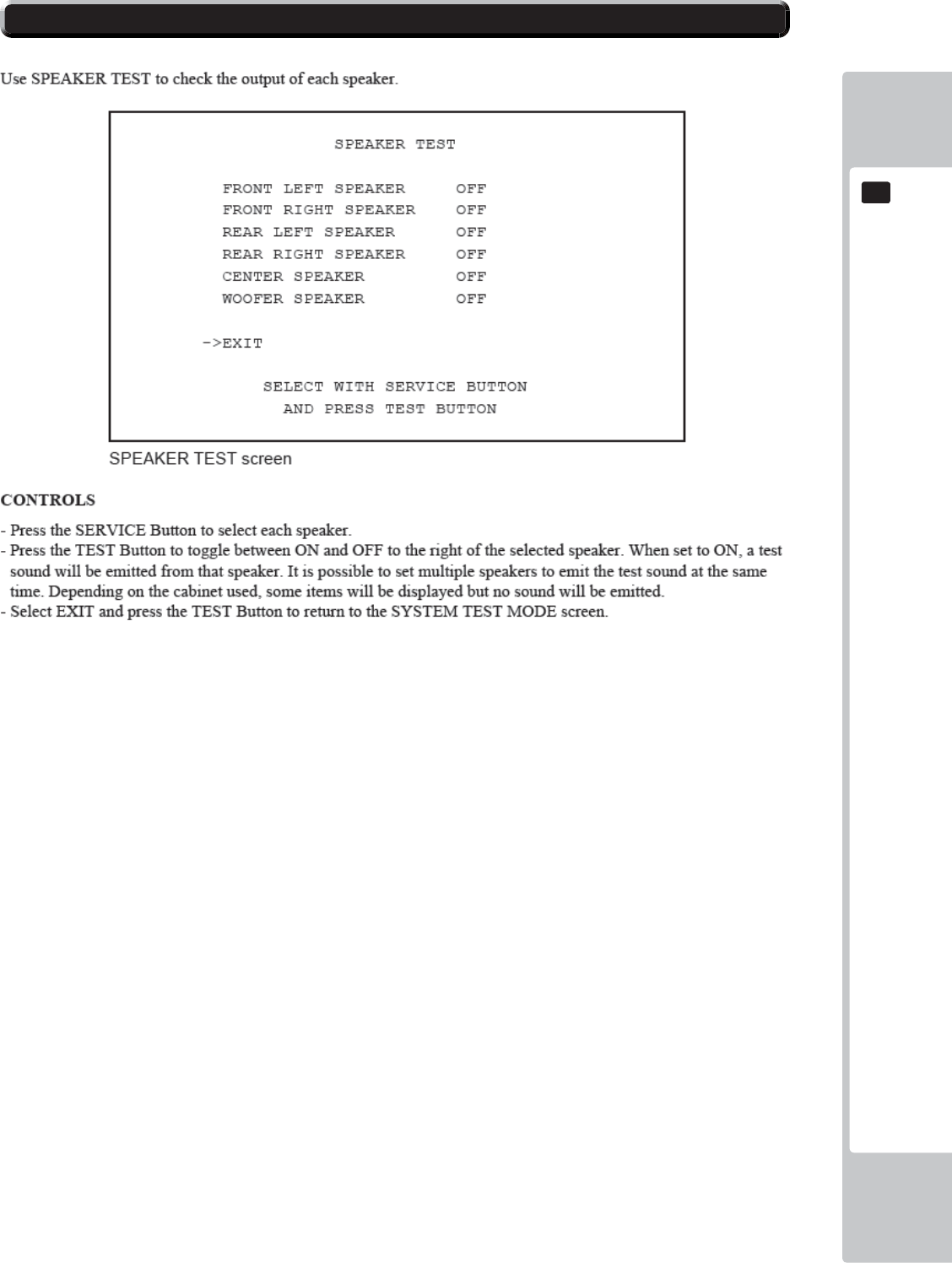
EXPLANATION OF TEST AND DATA DISPLAY
45
9
9
9-7 SPEAKER TEST
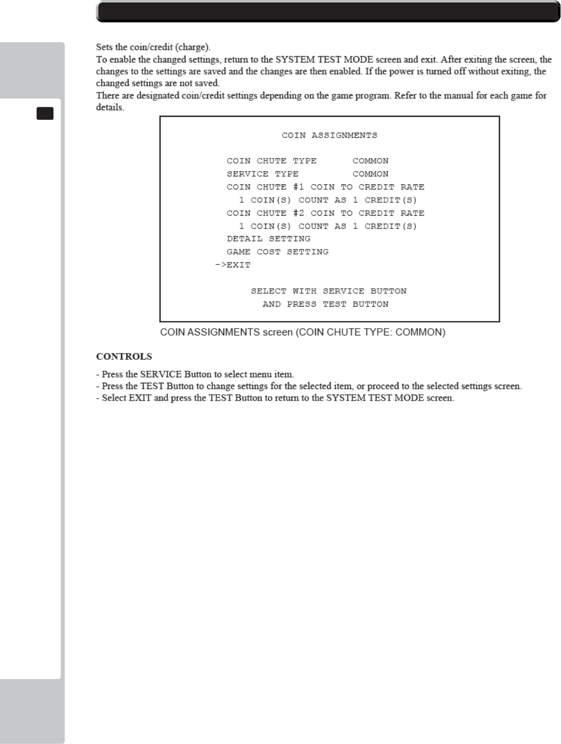
46
EXPLANATION OF TEST AND DATA DISPLAY
9
9
9-8 COIN ASSIGNMENTS
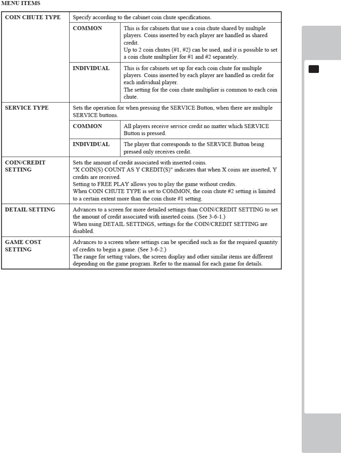
EXPLANATION OF TEST AND DATA DISPLAY
47
9
9
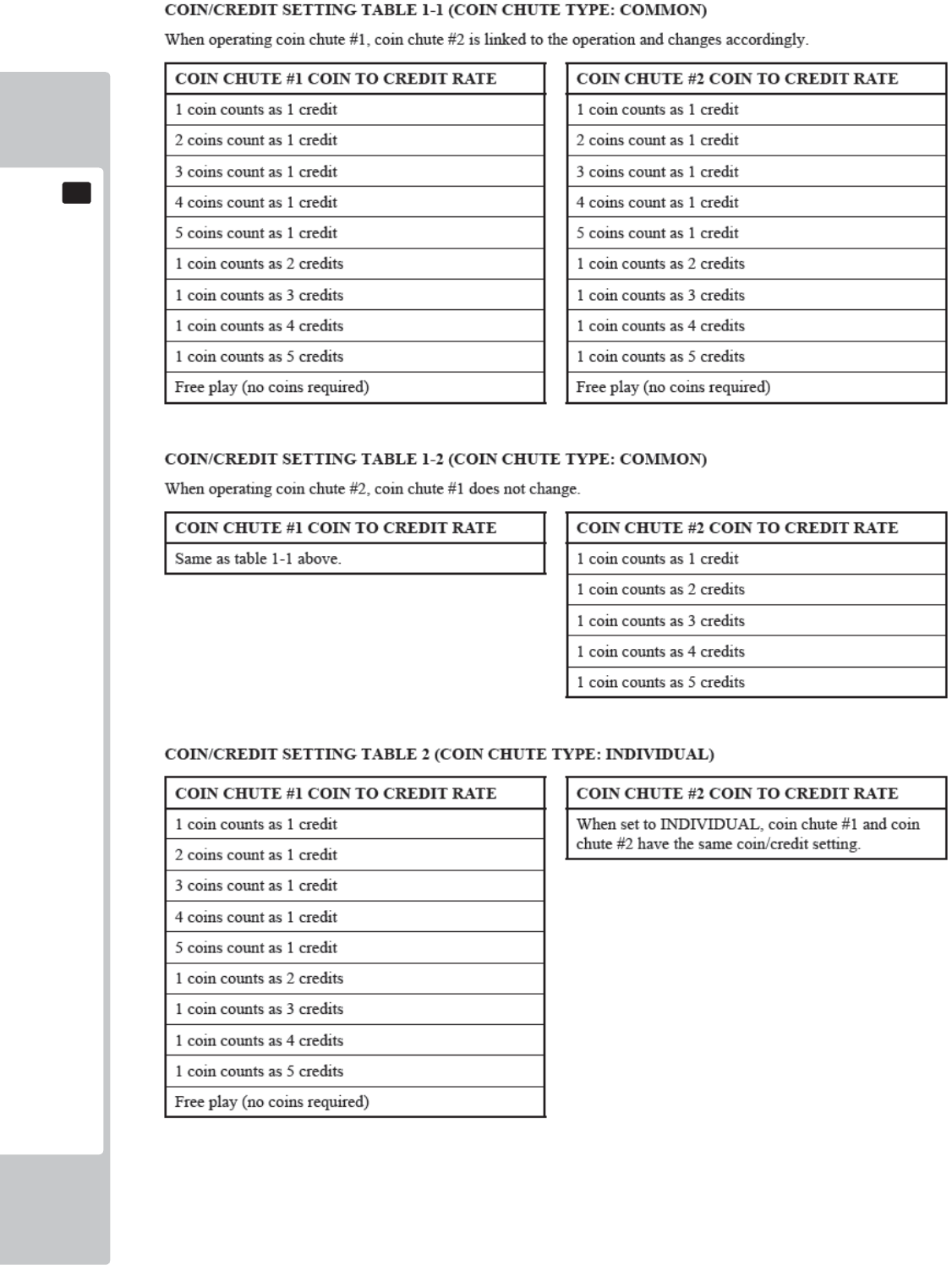
48
EXPLANATION OF TEST AND DATA DISPLAY
9
9
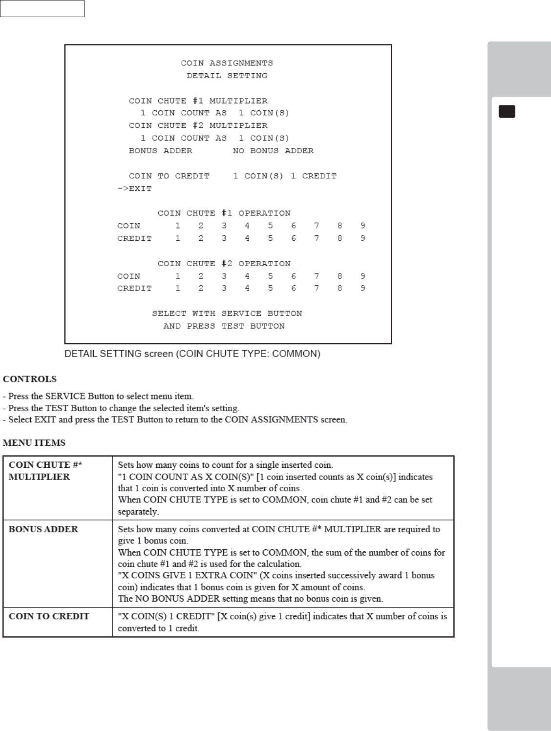
EXPLANATION OF TEST AND DATA DISPLAY
49
9
9
DETAIL SETTING
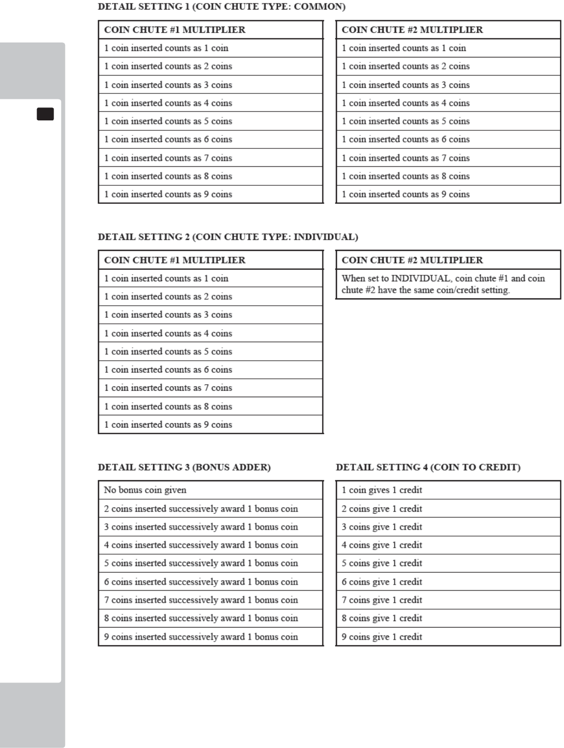
50
EXPLANATION OF TEST AND DATA DISPLAY
9
9
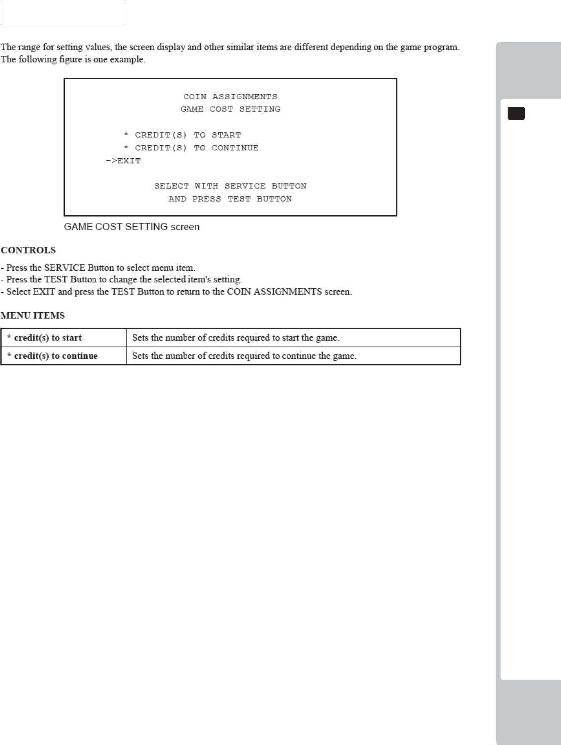
EXPLANATION OF TEST AND DATA DISPLAY
51
9
9
GAME COST SETTINGS
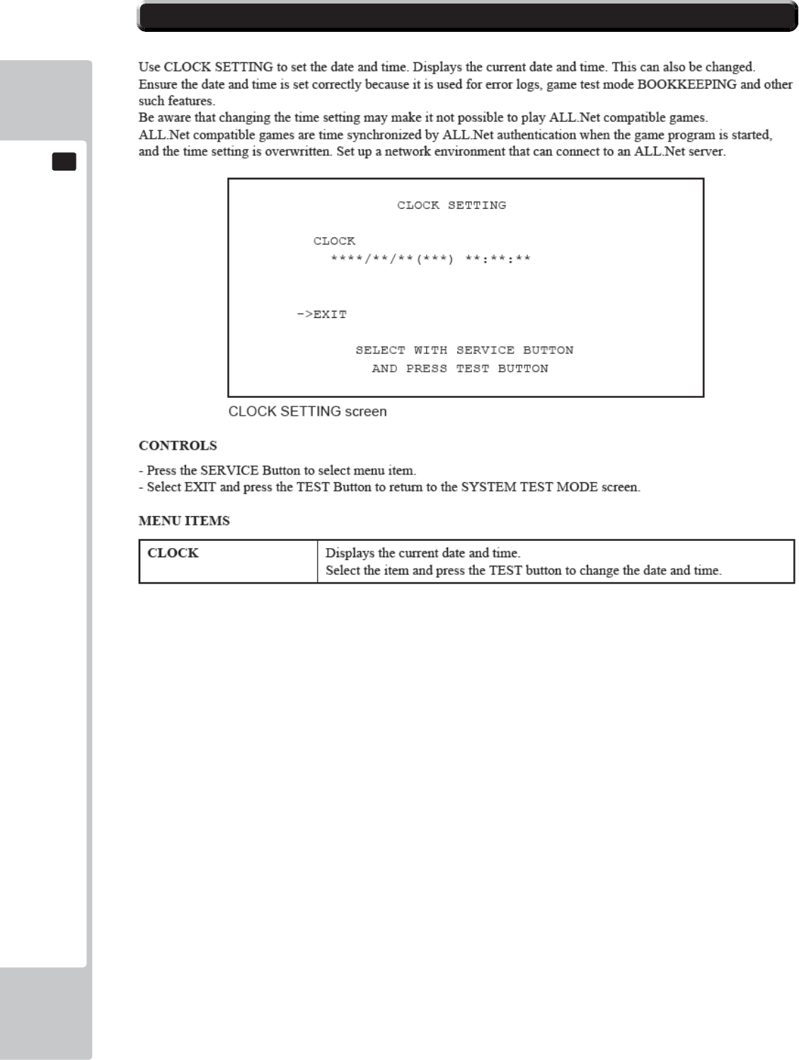
52
EXPLANATION OF TEST AND DATA DISPLAY
9
9
9-9 CLOCK SETTING
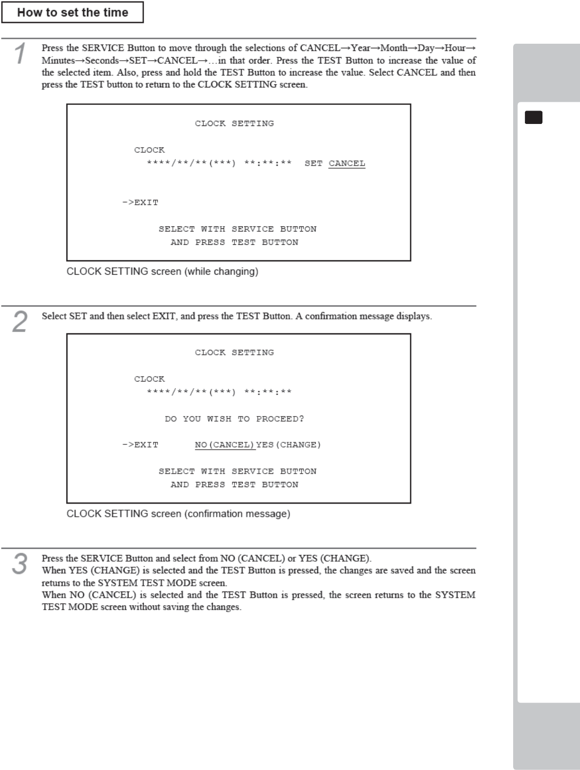
EXPLANATION OF TEST AND DATA DISPLAY
53
9
9
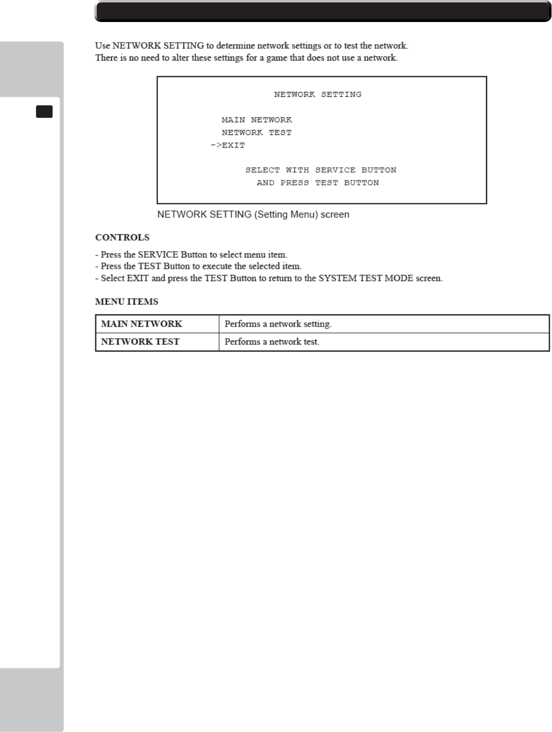
54
EXPLANATION OF TEST AND DATA DISPLAY
9
9
9-10 NETWORK SETTING
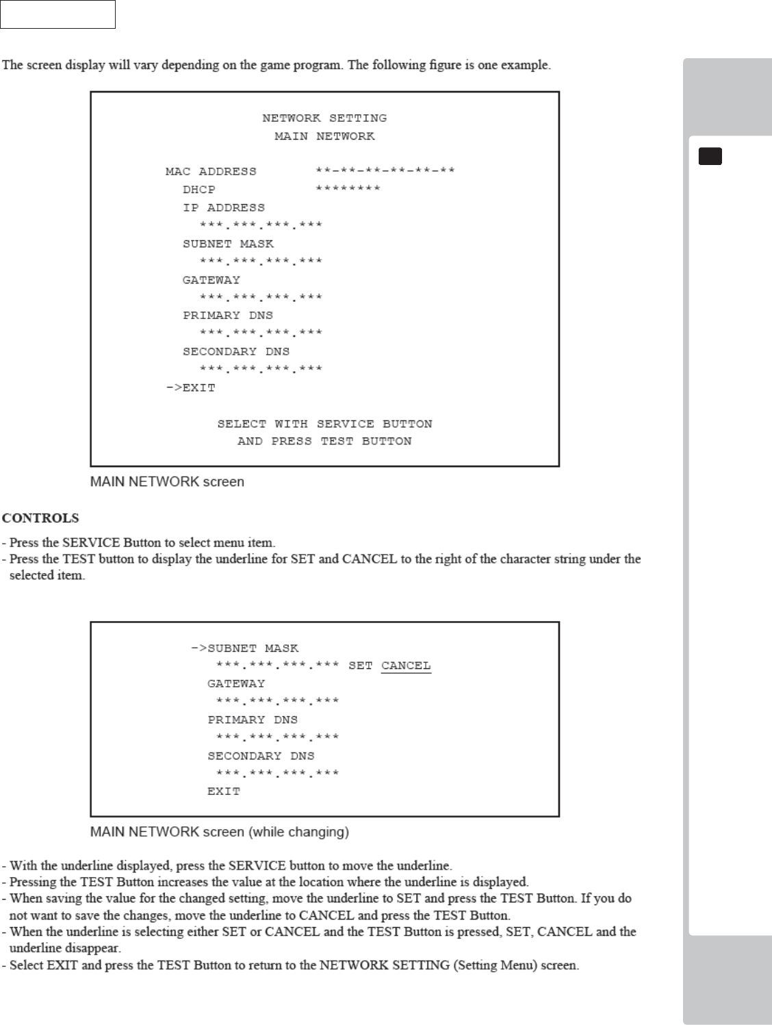
EXPLANATION OF TEST AND DATA DISPLAY
55
9
9
MAIN NETWORK
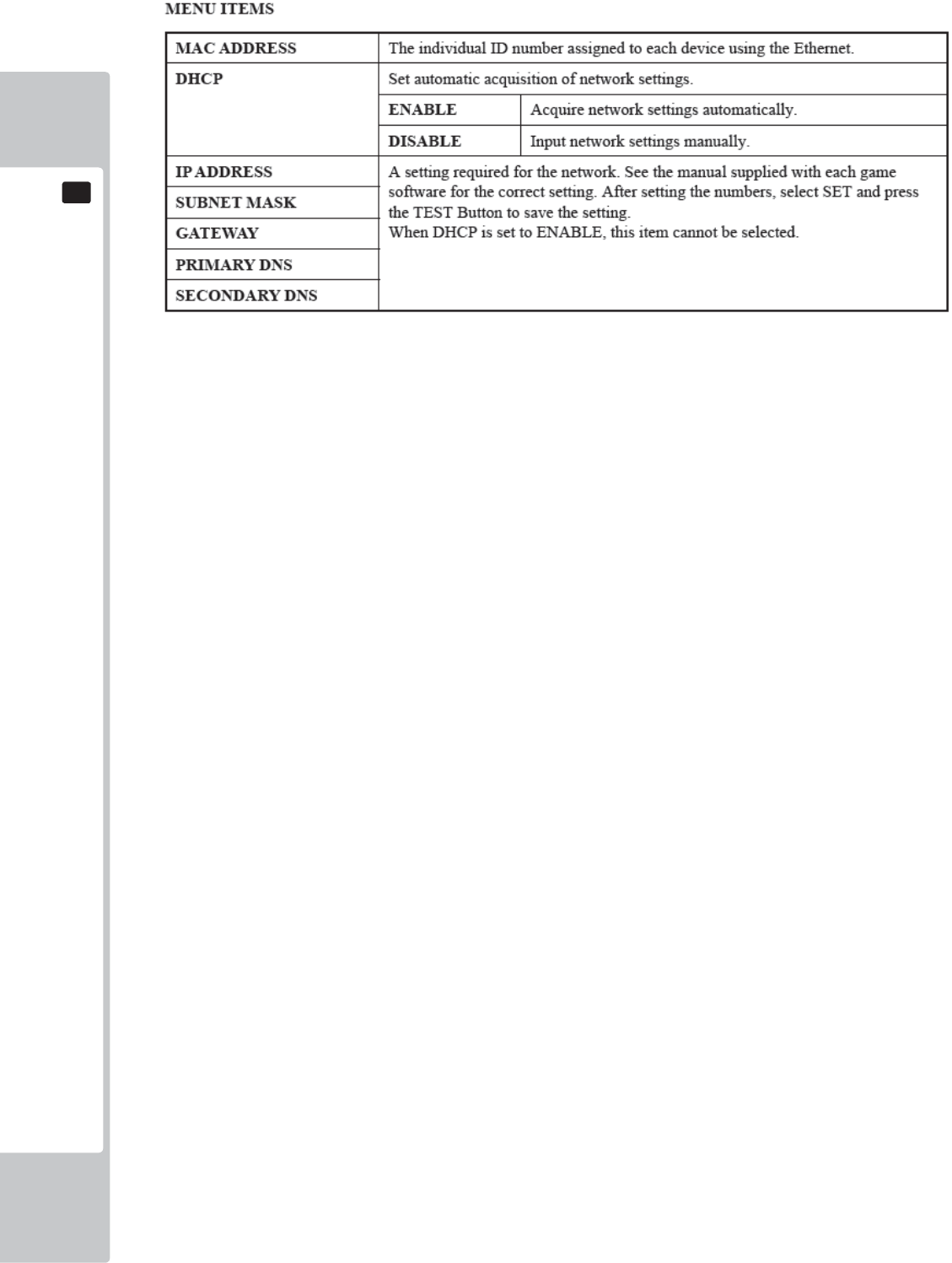
56
EXPLANATION OF TEST AND DATA DISPLAY
9
9
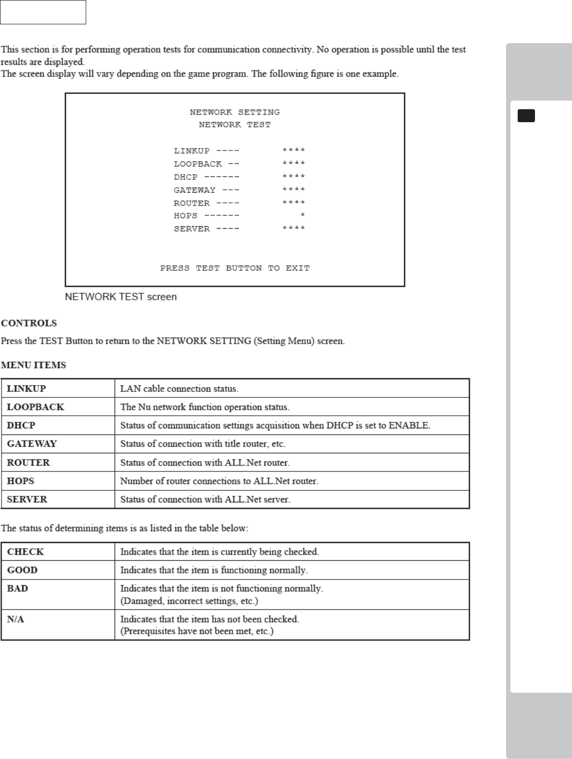
EXPLANATION OF TEST AND DATA DISPLAY
57
9
9
NETWORK TEST
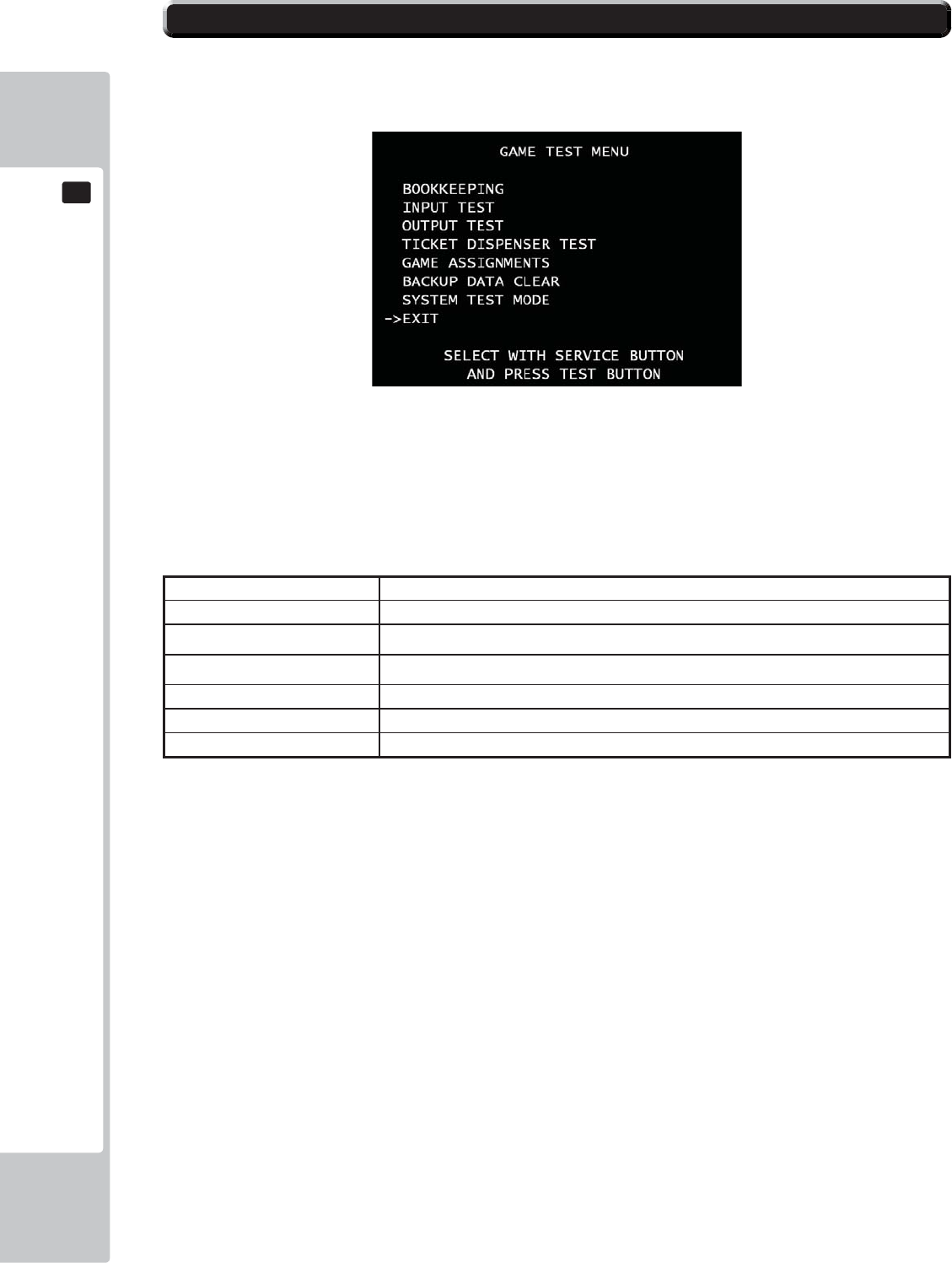
58
EXPLANATION OF TEST AND DATA DISPLAY
9
9
GAME TEST MENU
Press test button to enter GAME TEST MENU screen.
■Control
- Use the SERVICE Button to move the cursor to the desired test item.
- Press the TEST Button to confi rm selection of the item.
- Select EXIT and press the TEST Button to return to the SYSTEM TEST MODE screen.
■Menu Item
BOOKKEEPING Displays all recorded game data.
INPUT TEST Tests each input device used for the game.
OUTPUT TEST Tests each output device used for the game.
TICKET DISPENSER TEST Tests vending ticket machines.
GAME ASSIGNMENTS Adjusts all game settings
BACKUP DATA CLEAR Erases all types of game records.
SYSTEM TEST MODE Enter SYSTEM TEST MODE
9-11 GAME TEST MENU
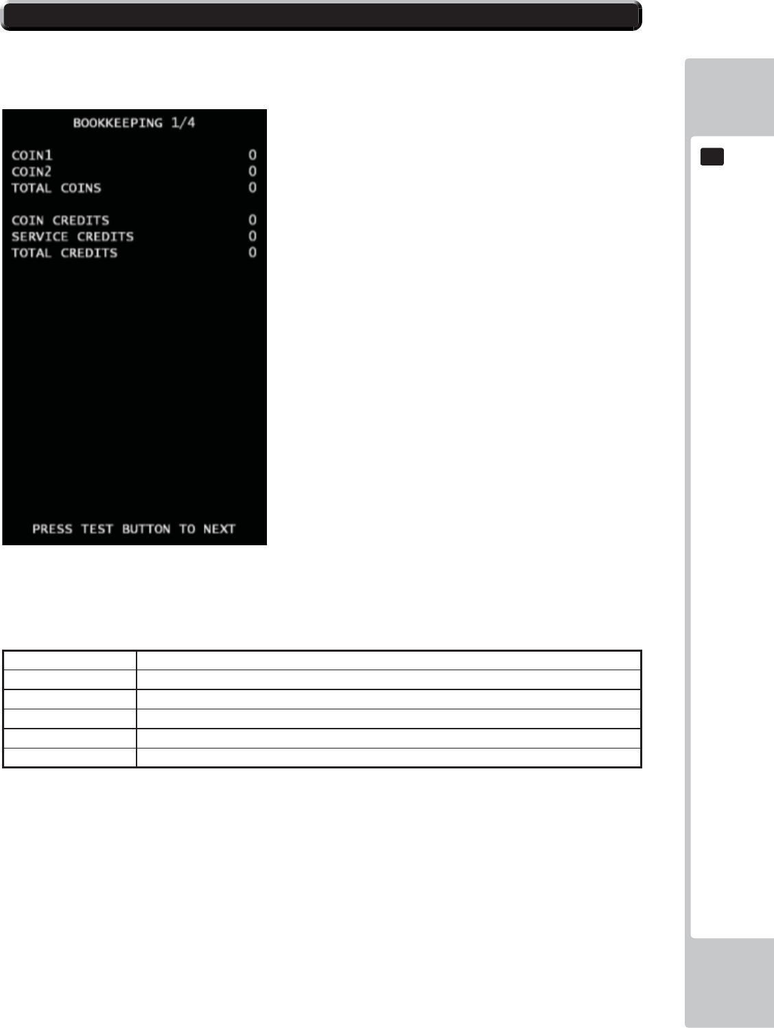
EXPLANATION OF TEST AND DATA DISPLAY
59
9
9
BOOKKEEPING(1/4)
Each game record can be viewed.
■Control
- Press the TEST Button to move to BOOKKEEPING 2/4 screen.
■Menu Item
COIN1 Number of coins inserted in coin chute 1.
COIN2 Number of coins inserted in coin chute 2.
TOTAL COINS Total Number of coins inserted in coin chute.
COIN CREDITS Number of credits for coins inserted.
SERVICE CREDITS Number of credits entered with the SERVICE Button.
TOTAL CREDITS Total number of all credits.
9-12 BOOKKEEPING
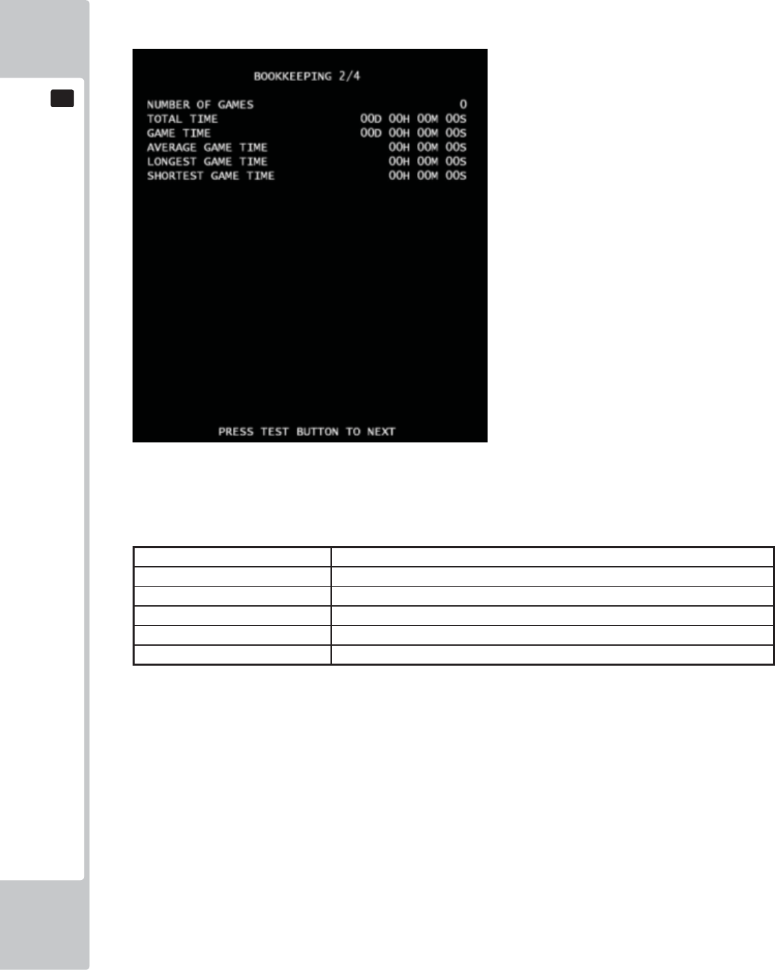
60
EXPLANATION OF TEST AND DATA DISPLAY
9
9
BOOKKEEPING(2/4)**Video Redemption
*It has difference text between Video Redemption mode and Amusement only mode for Bookkeeping 2/4.
■Control
- Press the TEST Button to move to BOOKKEEPING 2/4 screen.
■ Menu Item
NUMBER OF GAMES Total number of games played by a player.
TOTAL TIME Amount of time the cabinet has been in operation.
GAME TIME Amount of time the game has been played.
AVERAGE GAME TIME Average control time for one game.
LONGEST GAME TIME Longest play time for one game.
SHORTEST GAME TIME Shortest play time for one game.
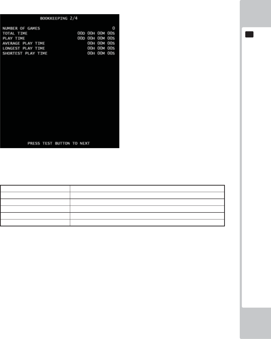
EXPLANATION OF TEST AND DATA DISPLAY
61
9
9
BOOKKEEPING(2/4) *Amusement only mode
■Control
- Press the TEST Button to move to BOOKKEEPING 3/4 screen.
■ Menu Item
NUMBER OF GAMES Total number of games played by a player.
TOTAL TIME Amount of time the cabinet has been in operation.
PLAY TIME Amount of time the game has been played.
AVERAGE PLAY TIME Average play time for one game..
LONGEST PLAY TIME Longest play time for one game.
SHORTEST PLAY TIME Shortest play time for one game.
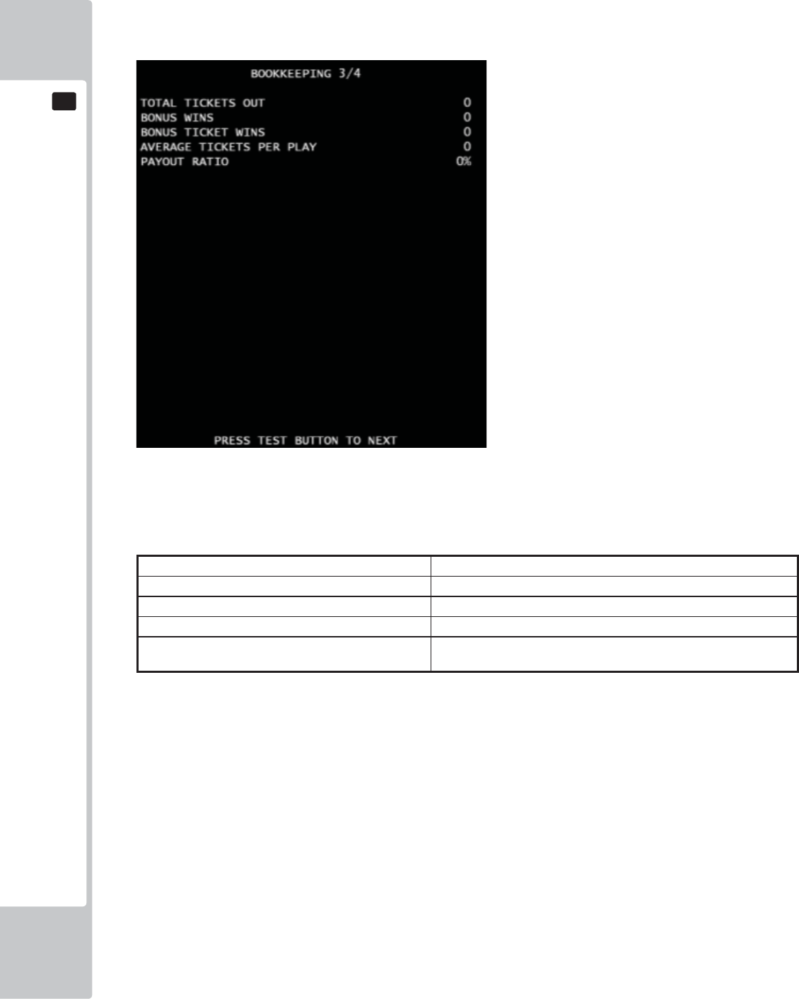
62
EXPLANATION OF TEST AND DATA DISPLAY
9
9
BOOKKEEPING(3/4)
*It is for Video Redemption mode only. On the Amusement only mode, text color changes to gray.
■Control
- Press the TEST Button to move to BOOKKEEPING 4/4 screen.
■ Menu Item
TOTAL TICKET OUT Total number of paid tickets..
BONUS WINS Amount of time of Super Bonus
BONUS TICKET WINS Amount of tickets paid by Super Bonus
AVERAGE TICKETS PER PLAY Average tickets paid number for one game.
PAYOUT RATIO Ticket Payout Rate by income. If the Payout Rate is over than 100, it
will display “100%.”
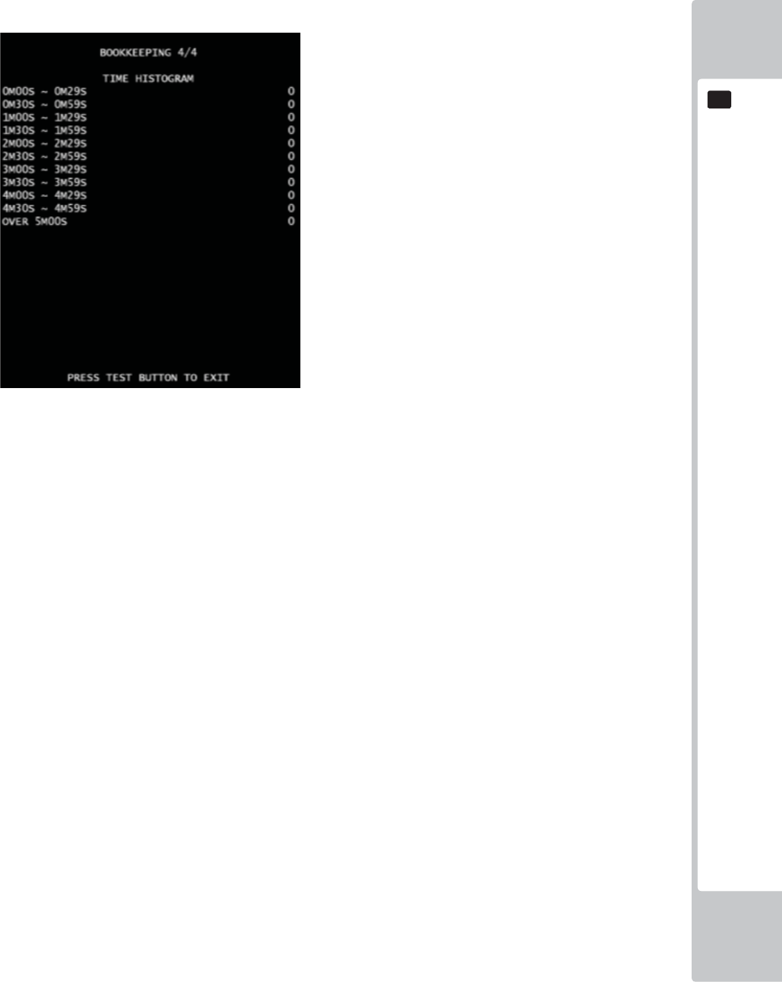
EXPLANATION OF TEST AND DATA DISPLAY
63
9
9
BOOKKEEPING(4/4)
■Control
- Press the TEST Button to return to GAME TEST MODE screen.
■Menu Item
Play time will be recorded into different lines by 30 seconds intervals.
All play times over 5 minutes are written into the line OVER 5M00S.
.
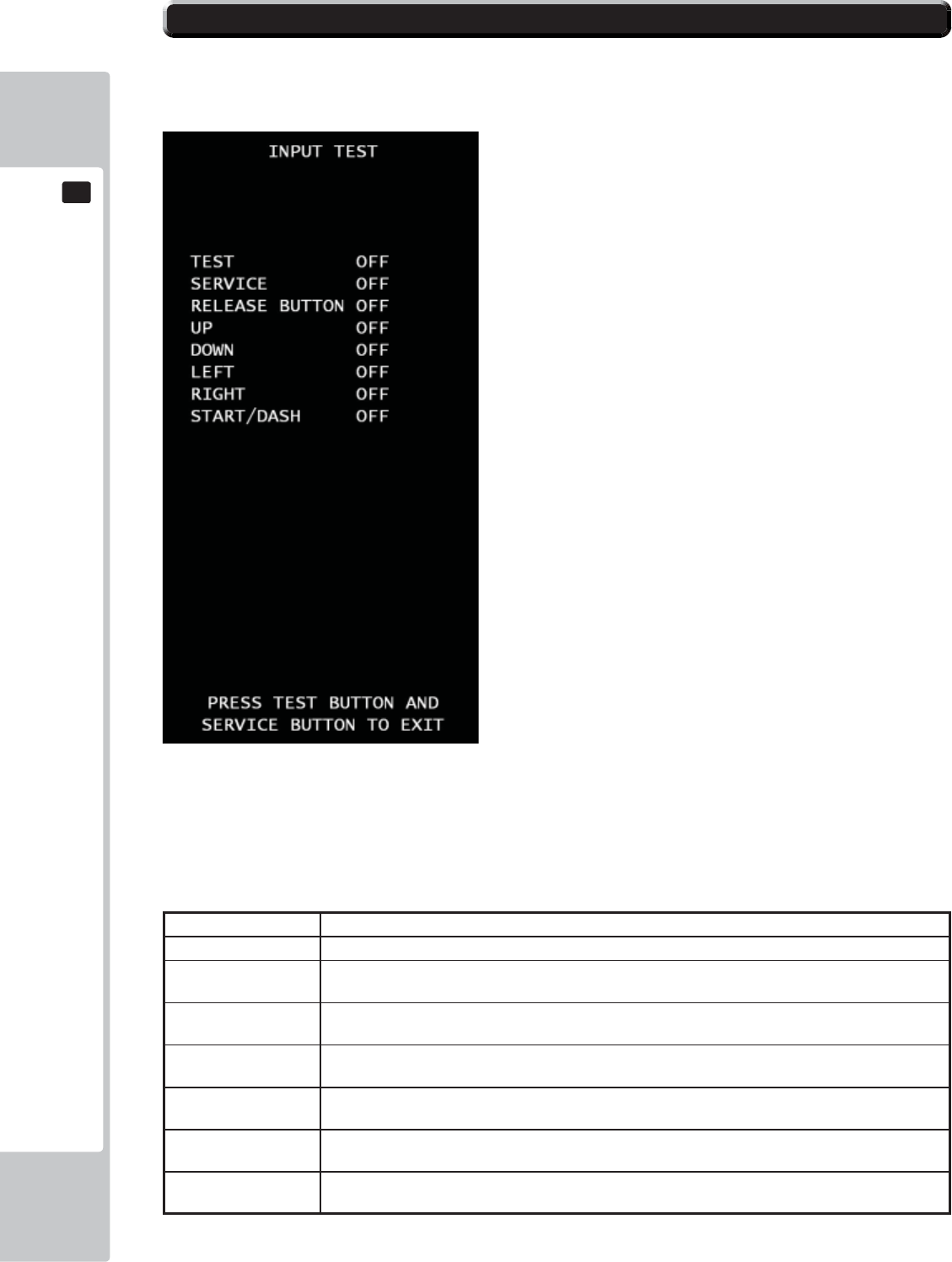
64
EXPLANATION OF TEST AND DATA DISPLAY
9
9
INPUT TEST
Look up the status of each input devices.
■Control
- Press TEST button and SERVICE button at the same time to return to GAME TEST MODE screen.
- When the corresponding menu items displays from “OFF” to “ON” or corresponding data reacts to the ac-
tion,
the device is then functional.
■Menu Item
TEST Press TEST button, this item will display “ON”, release the button, the item will display “OFF”.
SERVICE Press SERVICE button, this item will display “ON”, release the button, the item will display “OFF”.
RELEASE BUTTON Press ticket release button inside ticket vending box, this item will display “ON”, release the button,
the item will display “OFF”.
UP Press UP side of the direction pad, this item will display “ON”, release the button, the item will
display “OFF”.
DOWN Press Down side of the direction pad, this item will display “ON”, release the button, the item will
display “OFF”.
LEFT Press Left side of the direction pad, this item will display “ON”, release the button, the item will
display “OFF”.
RIGHT Press Right side of the direction pad, this item will display “ON”, release the button, the item will
display “OFF”.
START/DASH Press the START/DASH button, the item will display “ON”, release the button, the item will display
“OFF”
9-13 INPUT TEST
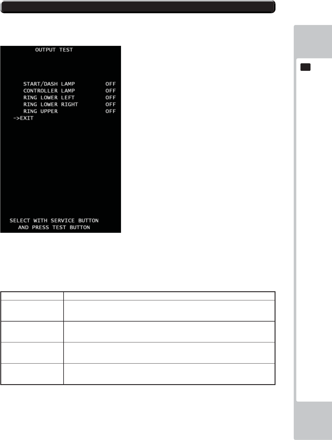
EXPLANATION OF TEST AND DATA DISPLAY
65
9
9
OUTPUT TEST
Test all the output devices utilized in game. Please test all the output devices in regular term.
■Control
- Use the SERVICE Button to move the cursor to the desired test item.
- Press the TEST Button to confi rm selection of the item.
- Select EXIT and press the TEST Button to return to GAME TEST MODE screen.
■Menu Item
START/DASH LAMP START/DASH button to light the lamp.
CONTROLLER LAMP The lamp of the direction button is on. Every time the test button is pressed, the color will dis-
play in the order RED-GREEN-BLUE-MAGENDA-CYAN-YELLOW-WHITE-OFF. Default is
“OFF”.
RING LOWER LEFT The lamp at the left ring of lower cabinet is on. Every time the test button is pressed, the color
will display in the order
RED-GREEN-BLUE-MAGENDA-CYAN-YELLOW-WHITE-OFF. Default is “OFF”.
RING LOWER RIGHT The lamp at the right ring of lower cabinet is on. Every time the test button is pressed, the color
will display in the order
RED-GREEN-BLUE-MAGENDA-CYAN-YELLOW-WHITE-OFF. Default is “OFF”.
RING UPPER The lamp at both sides of the screen is on. Every time the test button is pressed, the color will
display in the order RED-GREEN-BLUE-MAGENDA-CYAN-YELLOW-WHITE-OFF. Default
is “OFF”.
9-14 OUTPUT TEST
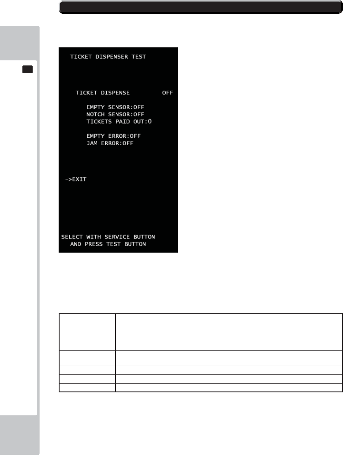
66
EXPLANATION OF TEST AND DATA DISPLAY
9
9
TICKET DISPENSER TEST
Test all the ticket vending devices utilized in game.
■Control
- Use the SERVICE Button to move the cursor to the desired test item.
- Press the TEST Button to confi rm selection of the item.
- Select EXIT and press the TEST Button to return to GAME TEST MODE screen.
■Menu Item
TICKET DISPENSE Press TEST button, this item will display “ON” and Ticket vending works. The test button is pressed
again, the item will display “OFF” and Ticket vending stops.
EMPTY SENSOR The status of ticket empty sensor. The item will display “OFF” of ticket box is enough to play to
vend tickets. If it’s not, the sensor will work and the item will display “ON”.
NOTCH SENSOR The status of notch sensor for the ticket. The item will display ”ON” when sensor fi nd the notch of
ticket.
TICKET PAID PUT Amount of tickets paid during this mode.
EMPTY ERROR The current status of ticket empty error. If the status is error, The item will display “ON”
JAM ERROR The current status of ticket jam error. If the status is error, The item will display “ON
If Error status is “ON”, please respond for each error, and then press Ticket
Release Switch to back normal.
9-15 TICKET TEST
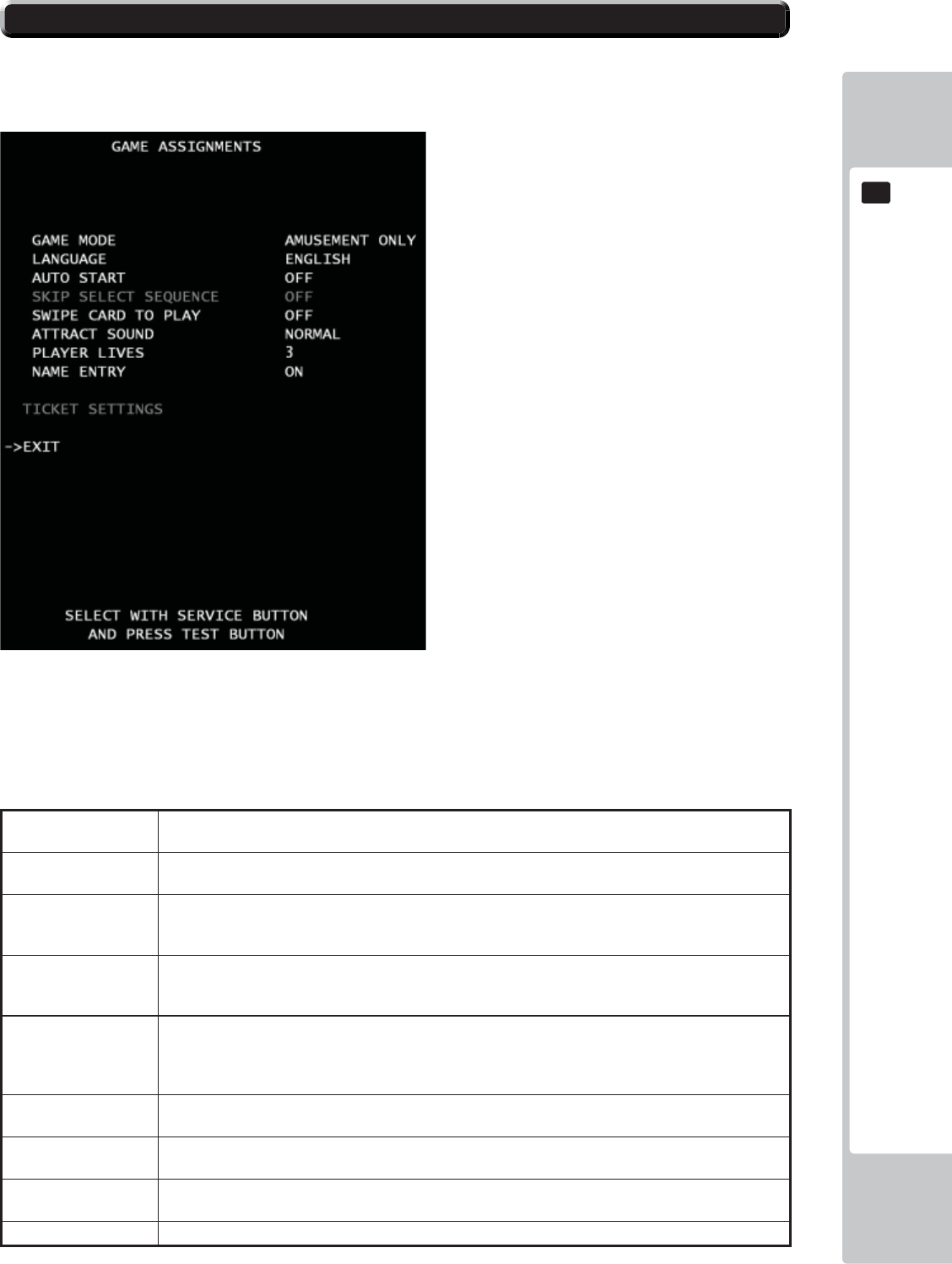
EXPLANATION OF TEST AND DATA DISPLAY
67
9
9
GAME ASSIGNMENTS
Game setting confi guration. The gray color means not select. It depends on each mode.
■Control
- Use the SERVICE Button to move the cursor to the desired test item.
- Press the TEST Button to confi rm selection of the item.
- Select EXIT and press the TEST Button to return to the GAME TEST MODE screen.
■Menu Item
GAME MODE Set “Ticket Redemption” or “Amusement Only” (no tickets). “TICKET REDEMPTION” is set by
default.
LANGUAGE Set a language. 6 options ENGLISH – FRENCH – ITALIAN – SPANISH – TURKISH - RUSSI to
choose from. ENGLISH is set by default.
AUTO START Can set automatic start. If the option is set to “ON”, The game will start without pressing start button
when credits is available to play. If the option is set to “OFF”, The game will wait to start until press-
ing start button as usual. “OFF” is set by default.
*SKIP SELECT SE-
QUENCE
Set skip a character select sequence. If the option is set to “ON”, it will skip and automatically select
players character with random. If the option is set to “OFF”, A character select sequence appears..
“OFF” is set by default *Ticket Redemption mode only available.
SWIP CARD TO
PLAY
Change the text at the screen bottom.
If the setting is set to “ON”, “SWIPE CARD TO PLAY” will be shown at the screen bottom. If the
setting is set to “OFF”, “INSERT COIN(S)”/“INSERT MORE COIN(S)” will be shown at the screen
bottom as usual. “OFF” is set by default.
ATTRACT SOUND Set the volume of attraction movie. 5 options NORMAL- OFF - 1/4 – 1/2 – 3/4 to choose from.
“NORMAL” is set by default.
**PLAYER LIVES Sets the number of monkeys (lives). 6 options 3 – 4- 5- UNLIMITED – 1 – 2 to choose from. 3 is set
by default.** Amusement only mode is available. 1 is fi xed on video redemption mode.
**NAME ENTRY Set name entry sequence. If the option is set to “ON”, high scored player can entry his name to rank-
ing . If the option is set to “OFF”, it will not ***Amusement only available.
*TICKET SETTING Move to TICKET SETTING MODE *Ticket Redemption mode only available.
9-16 GAME ASSIGNMENTS
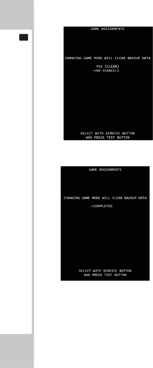
68
EXPLANATION OF TEST AND DATA DISPLAY
9
9
Changing game mode.
When game mode changes, below screen will be shown.
■Control
*Press SERVICE button to select menu item.
*Select “YES (CLEAR) and press TEST button to clear all backup data. When “COMPLETED” is displayed,
press TEST button again and return to GAME TEST MODE screen.
*Select “NO (CANCEL)” and press TEST button, no action will be executed and return to GAME ASSIGN-
MENTS screen directly.
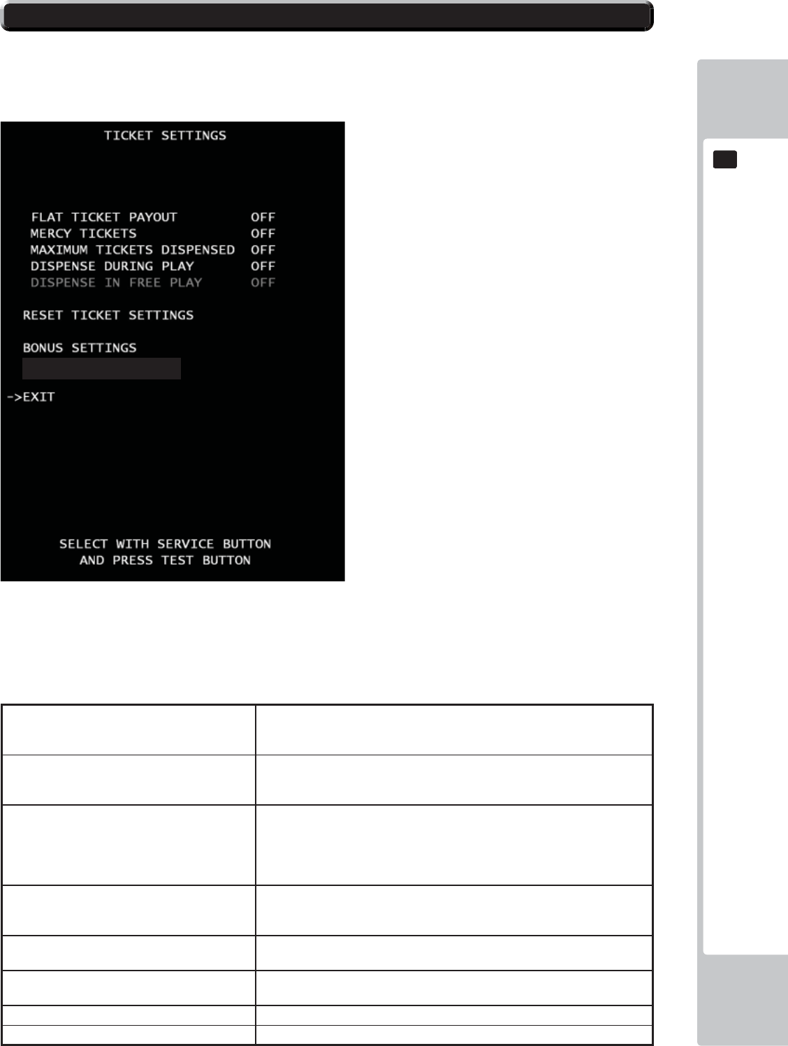
EXPLANATION OF TEST AND DATA DISPLAY
69
9
9
ATTENTION!!!
We recommend BACKUP DATA CLEAR when the Ticket payout setting and setting that related to Payout rate were
changed because some time cause confusion of BOOKKEEPING data.
■Control
- Use the SERVICE Button to move the cursor to the desired test item.
- Press the TEST Button to confi rm selection of the item.
- Select EXIT and press the TEST Button to return to the GAME ASSIGNMENT screen.
■Menu Item
FLAT TICKET PAYOUT Each player will receive the same amount of tickets,
Regardless of points scored. Every time the test button is pressed, the color
will display in the order +1 from 1 to 10. OFF is set by default.
MERCY TICKET Player will receive ticket(s) regardless of points
scored. Every time the test button is pressed, the number will display in the
order +1 from 1 to 5. OFF is set by default.
MAXIMUM TICKETS DISPENSED Sets the maximum number of tickets through the
dispenser for each game. Any value in excess of the
set value must be paid manually by attendant.. Every time the test button is
pressed, the number will display in the order +100 from 100 to 1000. OFF is
set by default.
DISPENSE DURING PLAY If set to ON, tickets will be paid during game play.
Default value is OFF, all tickets will be paid at the
end of the game. OFF is set by default.
DISPENSE IN FREE PLAY* Enables/disables ticket payout in FREE PLAY.
*This setting is used only in “FREE PLAY” mode.
RESET TICKET SETTING Set all of the TICKET SETTINGS back to the factory
default values.
BONUS SETTING Go to Bonus Settings
DIFFICULTY SETTING Go to Diffi culty Settings
DIFFICULTY SETTINGS
9-17 TICKET SETTINGS
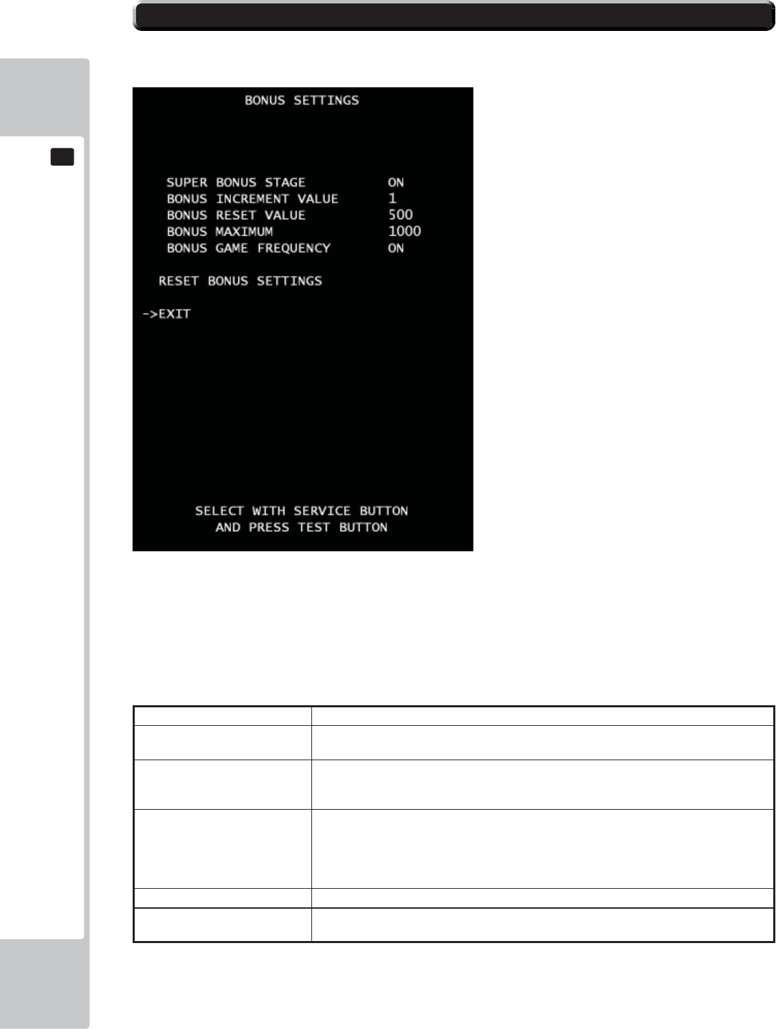
70
EXPLANATION OF TEST AND DATA DISPLAY
9
9
Ticket bonus setting.
■Control
- Use the SERVICE Button to move the cursor to the desired test item.
- Press the TEST Button to confi rm selection of the item.
- Select EXIT and press the TEST Button to return to the TICKET SETTING screen.
■Menu Item
SUPER BONUS STAGE If set to ON, the Bonus stage appears after a character pass the goal. ON is set by default.
BONUS INCREMENT VALUE Amount of points will increase for every game played.
If set to OFF, non progressive. 2 option “1” and “OFF” to choose from. 1 is set by default.
BONUS RESET VALUE The beginning/reset value of the Bonus
amount. Every time the test button is pressed, the number will display in the order +50
from 100 to 1000. Under 100, you can set 25, 50, 75. 500 is set by default.
BONUS MAXIMUM Sets the number of maximum progressive value.
*Please set “BONUS RESET VALUE” up fi rst. The
maximum number must be more than “BONUS
RESET VALUE” amount. Every time the test button is pressed, the number will display in
the order +50 from 100 to 1000. Under 100, you can set 25, 50, 75.1000 is set by default.
BONUS GAME FREQUENCY Use random frequency in Super Bonus game. ON is set by default.
RESET BONUS SETTING Set all of the BONUS SETTINGS back to the factory
default values.
9-18 BONUS SETTINGS
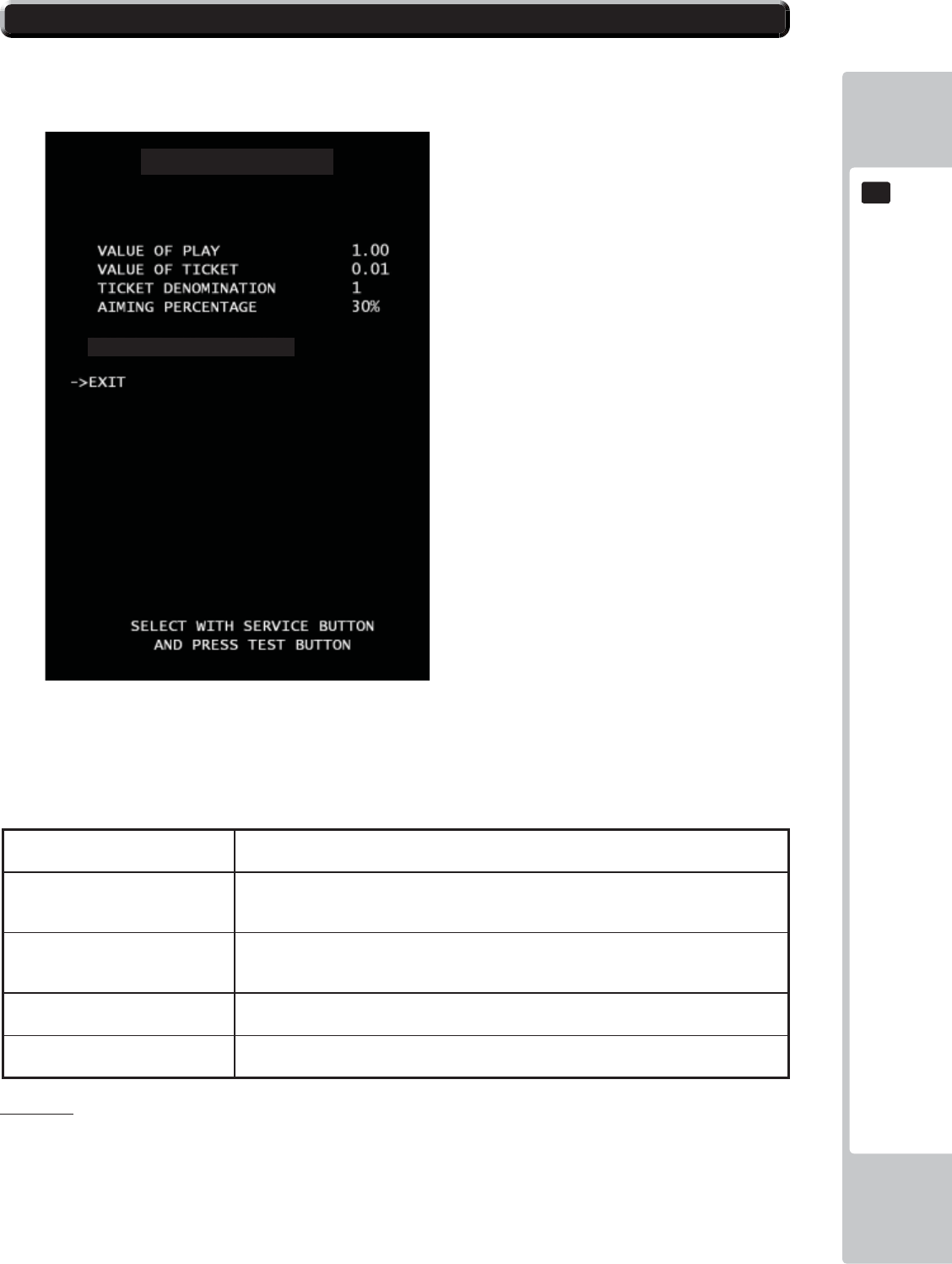
EXPLANATION OF TEST AND DATA DISPLAY
71
9
9
DIFFICULTY SETTING
Ticket OUTPUT setting.
■Control
- Use the SERVICE Button to move the cursor to the desired test item.
- Press the TEST Button to confi rm selection of the item.
- Select EXIT and press the TEST Button to return to the TICKET SETTING screen.
■Menu Item
VALUE OF PLAY Set monetary cost per play. Every time the test button is pressed, the number will display
in the order +0.01 from 0.2 to 2.0. 1.00 is set by default.
VALUE OF TICKET Set monetary value of each ticket. Every time the test button is pressed, the number
will display in the order +0.01 from 0.01 to 0.10. Under 0.01, you can set 0.001, 0.002,
0.005. 0.01 is set by default.
TICKET DENOMINATION This setting is used only if the game is using 2
points ticket. If you are using a 2 points ticket,
set this value to 2. 1 is set by default.
AIMING PERCENTAGE Set targeting percentage. Every time the test button is pressed, the number will display
in the order +5 from 5% to 80%. 30% is set by default.
RESET SETTINGS Set all of the DIFFICULTY SETTINGS back to the
factory default values.
DIFFICULTY SETTINGS
RESET DIFFICULTY SETTINGS
Please note:
If any changes are made to either DIFFICULTY settings or VALUE settings then it is recommended that the BACK UP DATA is
also cleared. Please refer to Section 9-20 (Page 74) of this manual.
9-19 DIFFICULTY SETTINGS
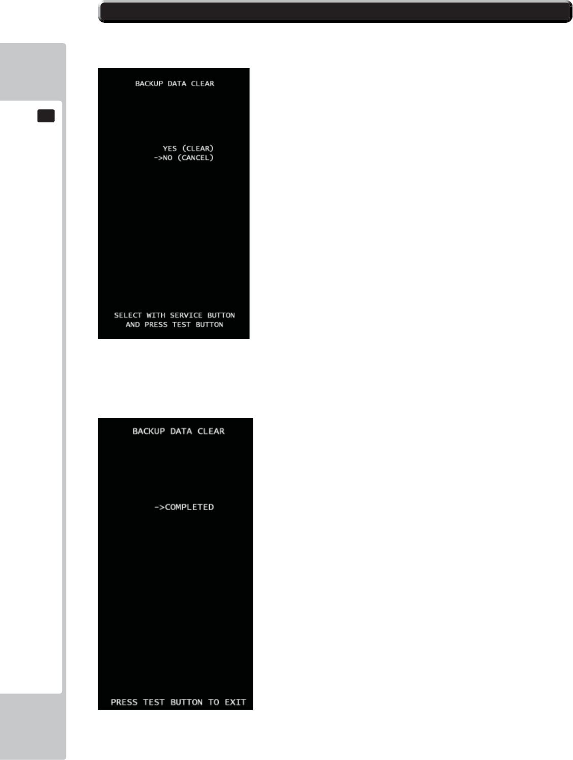
72
EXPLANATION OF TEST AND DATA DISPLAY
9
9
BACKUP DATA CLEAR
Clear all game records
■Control
*Press SERVICE button to select menu item.
*Select “YES (CLEAR) and press TEST button to clear all backup data. When “COMPLETED” is dis-
played, press TEST button again and return to GAME TEST MODE screen.
***Select “NO (CANCEL)” and press TEST button, no action will be executed and return to GAME TEST MODE screen
directly.
9-20 BACKUP DATA CLEAR

EXPLANATION OF TEST AND DATA DISPLAY
73
9
9
Ticket Dispenser Error
EMPTY ERROR
This message will be displayed immediately in game mode if the tickets are not
fi lled and set in ticket BIN & Dispenser. Fill tickets and press Ticket Release Switch to back
normal.
JAM ERROR
This message will appear when ticket(s) are jammed on TICKET DISPENSER.
After remove jammed tickets then fi ll the tickets correctly then press Ticket
Release Switch to back normal.
MAX TICKETS ERROR
This message will be appeared when the ticket payout numbers over the number
that set at MAXIMUM TICKETS DISPENSE. Verify the ticket number on screen
then press Ticket Release Switch to back normal.
9-21 TICKET ERROR
74
CONTROL UNIT
10
• When working with the product, be sure to turn the power off. Working with the
power on may cause an electric shock or short circuit.
• Be careful not to damage the wires. Damaged wires may cause an electric
shock, short circuit or present a risk of fi re.
• Exercise due caution in performing soldering work. If soldering iron is handled
carelessly, there could be fi res or burns.
• When fastening plastic parts, be careful not to tighten screws or nuts excessively.
If these are tightened to excess, parts could be damaged, resulting in injuries
from fragments, etc.
• After the unit has been disassembled and reassembled again, check carefully
that the unit has been reassembled correctly.
• Once the product has been disassembled, use slack preventive agent. Coat
screws with suitable amounts of this agent and then tighten them. If this agent is
not used, the product might start rattling or come apart.
• Use the slack preventive agent prescribed in these instructions. If any other
agent is used, there could be chemical changes that inhibit the use of screws
and part surfaces could be damaged.
• Be careful not to damage or lose small parts or screws.
• When a part has been replaced, be sure to always make adjustments and
check conditions in Test Mode.
10 CONTROLLER UNIT(S)
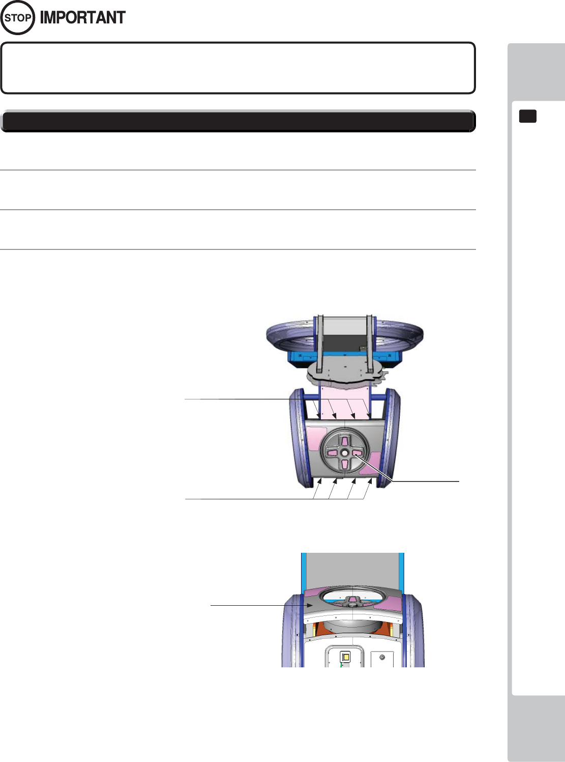
CONTROL UNIT
75
10
10-1 REMOVING THE CONTROLLER
Be sure to perform TEST in the INPUT ASSIGNMENTS in the Game Test Mode after
replacing or adjusting switches.
A 5 mm hexagonal wrench is required for the following procedure.
1
Turn off the power.
2
Remove the 8 hexagon socket button head screws from both sides of the Control Panel’s front and back.
3
Gentle lift the Control Panel Cover and place to one side.
10-1 FIG. 01
D-PAD
Remove the (4) fi xings from the rear
of the Control Panel Cover
Remove the (4) fixings from the
front of the Control Panel Cover
10-1 FIG. 02
Carefully raise the Control
Panel Cover
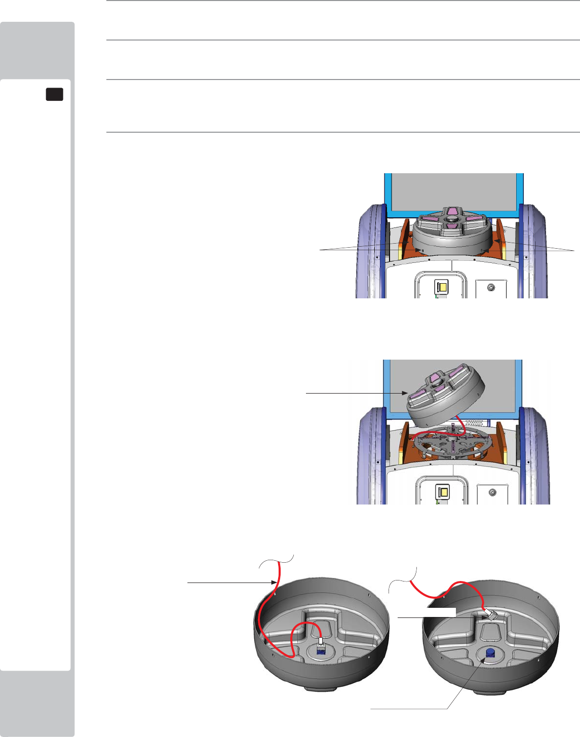
76
CONTROL UNIT
10
4
Locate the (6) fi xings, 3 positioned either side of the D-Pad and remove.
5
Once all (6) fi xings have been removed, carefully lift the D-Pad.
6
Once the D-pad has cleared the mechanics of the Controller, carefully overturn the D-Pad cover to locate
the Button and Button harness.
7
Holding the Lamp housing between your fi nger and thumb, gently twist as you pull the Lamp housing away
from the Button housing
Remove the (3) fixings from either
side of the D-PAD (6 in total)
10-1 FIG. 03
10-1 FIG. 04
10-1 FIG. 05
Flip the D-PAD cover over to reveal the
Button and Lamp Housing
Button Housing
Lamp Housing
Harness
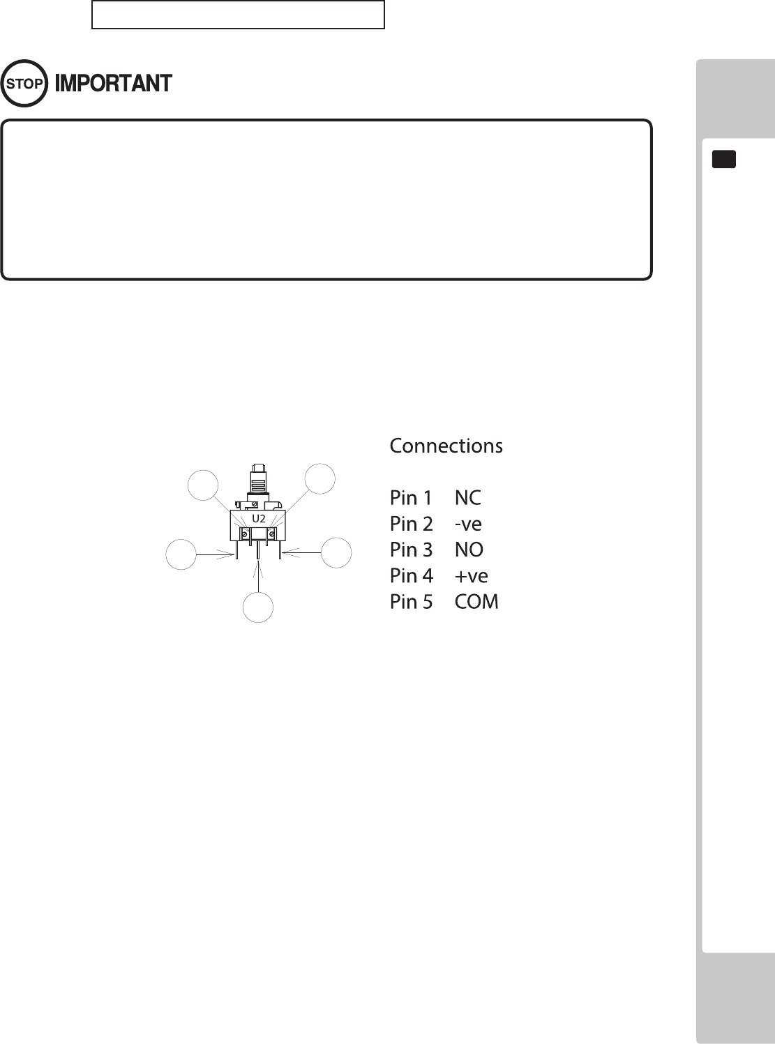
CONTROL UNIT
77
10
BULB/LED REPLACEMENT
• Be sure to replace the lamp like for like. Replacing the lamp or LED with a
different type/value may cause malfunction, electrical component failure or
even a fi re hazard.
• Take care when replacing 'Glass' bulbs. The integrity of a glass bulb may be
impaired. Use protective gloves and/or eye wear when removing as the glass
may shatter and cause injury.
IMPORTANT: This game uses an LED within the DASH Button Assy.
10-2 FIG. 06
78
GRAPHICS DISPLAY
11
Responding to breakdown or abnormality
● If smoke or a strange odor appears, immediately unplug the power cable from
the power source.
Continuing to use the product may cause a fi re or an electric shock. Ensure
that smoke is no longer emitted, and contact the point of purchase.
● If nothing displays on the screen, immediately unplug the power cable from
the power source.
Continuing to use the product may cause a fi re or an electric shock. Contact
the point of purchase and request an inspection.
● If water or a foreign object enters the monitor’s interior, immediately unplug the
power cable from the power source.
Continuing to use the product may cause a fi re or an electric shock. Contact
the point of purchase and request an inspection.
● If the monitor is dropped or the cabinet is damaged, immediately unplug the
power cable from the power source.
Continuing to use the product may cause a fi re or an electric shock. Contact
the point of purchase and request an inspection.
During operation
● Do not repair, reconstruct, or disassemble the monitor.
The monitors interior contains high voltage parts. A fi re or an electric shock
could result.
For inspections, adjustments, and repair of the monitors interior, request work
from the point of purchase.
● Do not insert foreign objects.
If metal objects or fl ammable materials such as paper are inserted into the
interior through ventilation openings or other apertures, an electric shock could
result.
● In the event of a thunder storm, do not touch the product or the power cable.
An electric shock could result.
● Make sure to perform appropriate adjustments. Do not operate
the product when the screen is fl ickering, distorted, or experiencing other
abnormalities. Images from an improperly adjusted screen could cause
players and other customers to experience dizziness, headaches, and other
ailments.
11-1 SAFETY PRECAUTIONS WHEN HANDLING THE MONITOR
11 GRAPHICS DISPLAY
GRAPHICS DISPLAY
79
11
CLEAN THE SCREEN DAILY.
11-2 CLEANING THE SCREEN SURFACE
● Use a soft, dry cloth (fl annel-type) to wipe away dirt. Do not use materials such
as coarse mesh gauze.
● Alcohol (ethanol) is the recommended solvent for removing dirt. When using a
cleaning agent, follow the precautions below.
- Dilute neutral cleaning agents for home use with water. Soak a soft cloth in the
solution, and wring it thoroughly before wiping the screen.
- Do not use abrasive cleaning agents or powders, or cleaning agents
containing bleach.
- Do not use alkaline cleaning agents such as glass cleaners, or solvents such as
thinners.
● Do not scrub or scratch the screen surface with abrasive materials such as
brushes or scrub brushes.
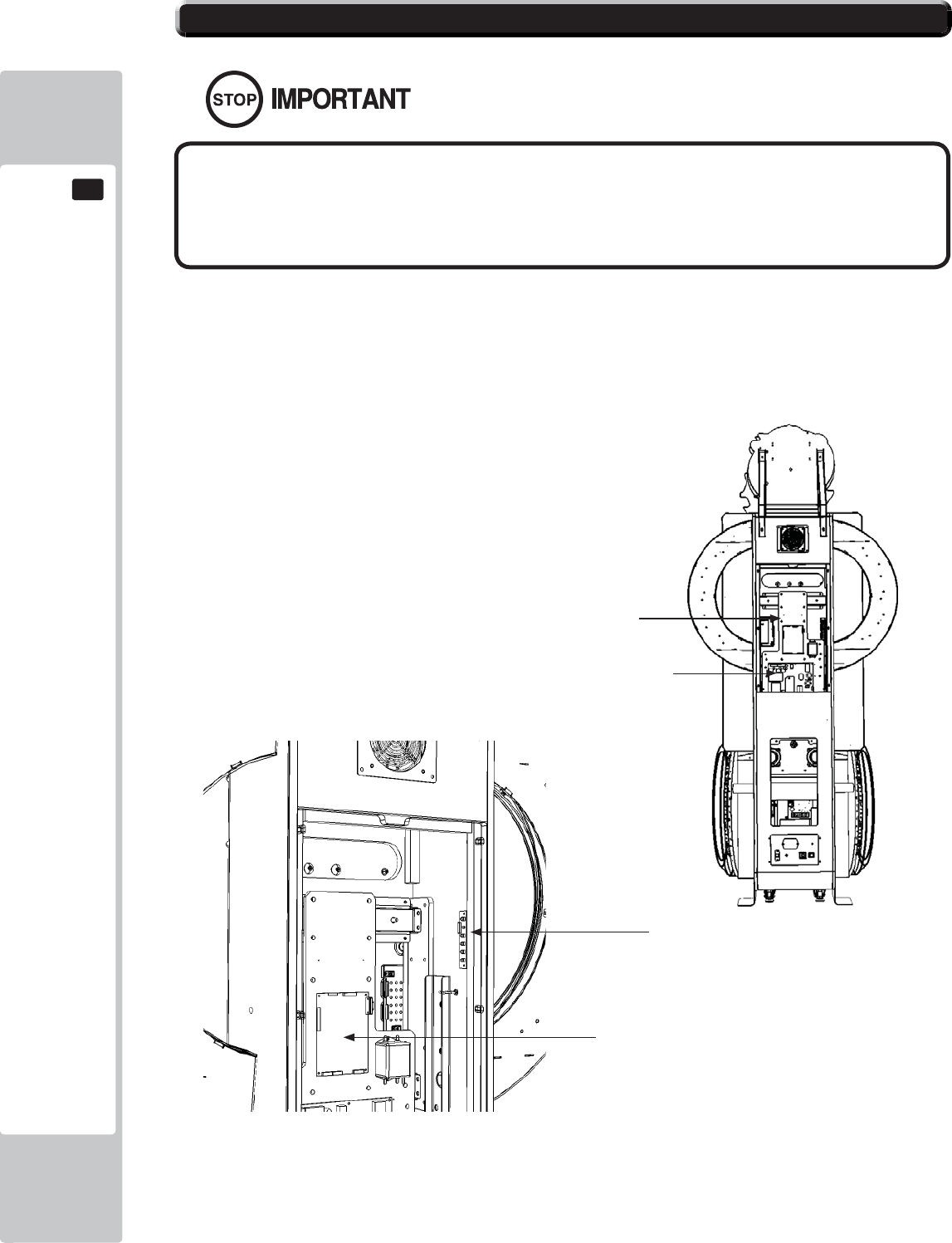
80
GRAPHICS DISPLAY
11
11-3 ADJUSTMENT METHOD
All adjustment values are set accurately at the time of shipping from the
factory. Do not readjust these values needlessly or apply adjustments not
specifi ed in this manual. The display may not appear properly if the values
are incorrect.
CONTROL - ADJUSTMENT PROCEDURE
This sections explains basic control procedures for making adjustments using the buttons on
the 'Monitor Adjustment Board'
This Adjustment Board, and the
Monitor Power Supply are located
behind the Rear Door.
11-3 Fig. 01
11-3 Fig. 02
Power Supply
LCD Driver Bd
55” LCD Panel
LCD Controller PCB
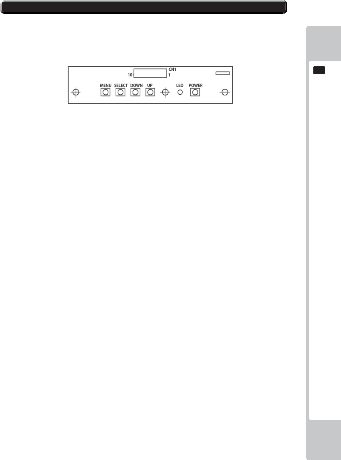
GRAPHICS DISPLAY
81
11
11-3 ADJUSTMENT METHOD
Button Names and Functions
MENU: Turn the Picture Menu display ON and OFF.
SELECT: Gains entry to the Item selected in the menu. (Highlights in Yellow when selected)
Exits the Item adustment. Any changes made during this
operation are actioned.
DOWN: Moves the cursor (Black Bar) down to select a menu item.
Decrease the value of, or change, a selected menu item.
UP: Move the cursor (Black Bar) up to select a menu item.
Increase the value of, or change, a selected menu item.
LED: LED illuminates green: Monitor is operating.
LED fl ashes red: Power is off.
POWER: Turns the LCD Display ON and OFF. (Usually, it’s not necessary to operate.)
11-3 Fig. 03
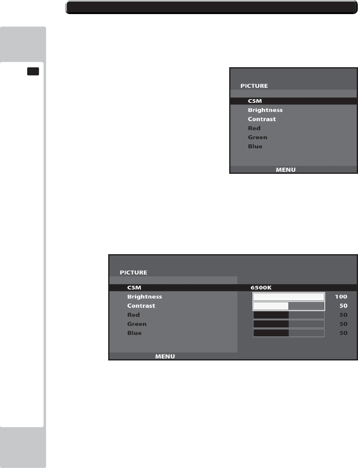
82
GRAPHICS DISPLAY
11
11-3 ADJUSTMENT METHOD
On-Screen Display (OSD)
Press the MENU Button while the OSD is not displayed to bring up the Picture Menu.
On the Picture Menu, it is possible to perform various screen adjustments.
Use the UP and DOWN Buttons to move the ‘Black Bar’to the item you want to adjust.
After selecting the desired item, pressing the SELECT Button will extend the MENU Screen and allow
adjustments to be changed.
Within each item, press the SELECT Button to exit the adjustment screen. The adjustment values at this time will be
saved simultaneously.
The current options are set at :
CSM - 6500K
Brightness - 100
Contrast - 50
11-3 Fig. 04
11-3 Fig. 05
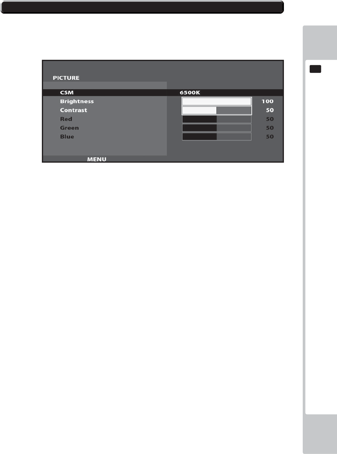
GRAPHICS DISPLAY
83
11
11-3 ADJUSTMENT METHOD
On-Screen Display (OSD) <continued>
Available Settings
CSM (Selects Operation Mode))
Selection availble - 6500K - 9300K - USER
BRIGHTNESS (Adjust Brightness)
Adjust screen Brightness. - Values: 0 - 100
(0” being the darkest setting, and “100” being the brightest)
CONTRAST (Adjust Contrast)
Adjust Contrast level. - Values: 0 - 100
(0” having the least amount of difference between light and dark, and “100” having the most)
NOTE : The Red, Green, and Blue adjustments are unavailable in the Mode of Operation selected on the Screen
shown in 11-3 Fig. 06. These adjustments can only be made is the CSM option is set to ‘User’.
11-3 Fig. 06
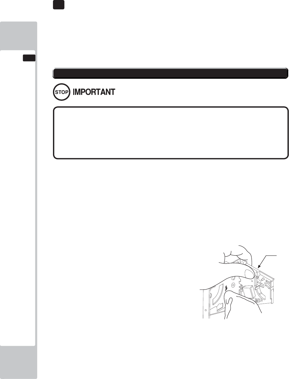
84
COIN HANDLING
12
12 COIN HANDLING
If the coin is not rejected when the REJECT button is pressed, open the coin chute door and open the
selector gate. After removing the jammed coin, put a normal coin in and check to see that the selector
correctly functions.
The Coin Selector should be cleaned once every 3 months.
When cleaning, follow the procedure below:
12-1 FIG 1
● Remove and clean smears by using a soft cloth dipped in water or diluted
chemical detergent and then squeezed dry.
● Never apply machine oil, etc. to the Coin Selector.
● After cleaning the Coin Selector, insert a regular coin in the normal
working status and ensure that the selector correctly functions.
12-1 CLEANING THE COIN SELECTOR
GATE
Handling the Coin Jam
1
2
3
Turn the power for the machine OFF. Open the Coin Chute Door
Remove the Coin Selector from the Coin Chute Door
Open the gate and dust off by using a soft brush (Small soft Paint Brush, etc.)
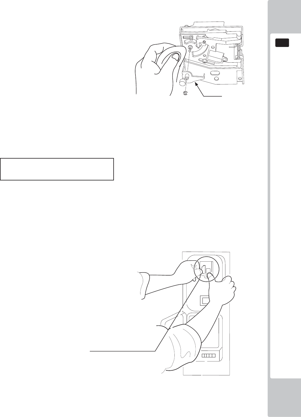
COIN HANDLING
85
12
Remove and clean smears by using a soft cloth dipped in water or diluted chemical detergent
and then squeezed dry.
Remove the CRADLE.. When removing the
retaining ring (E ring) be very careful so as not
to bend the rotary shaft.
Remove stain from the rotary shaft and shaft
receiving portions by wiping off with a soft
cloth. etc.
After wiping off as per previous step, further apply a dry cloth to completely dry the Coin
Selector.
CLEANING THE COIN SELECTOR (MECHANICAL).
Once every month, when performing the Coin SW Test, simultaneously check the following:
Does the Coin Meter count satisfactorily?
Does the coin drop into the cashbox correctly?
Is the coin rejected when inserted while keeping the REJECT Button pressed down?
Coin Insertion Test
12-1 FIG 2
12-1 FIG 3
CRADLE
Insert a coin while keeping
the REJECT Button pressed
down and check if it is
rejected.
1
2
3
4
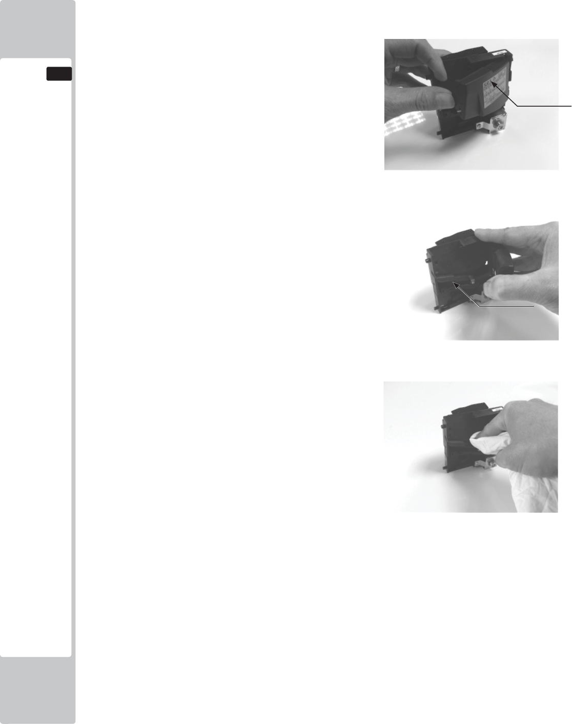
86
COIN HANDLING
12
Remove and clean smears by using a damp soft
cloth dipped in water. DO NOT use any diluted
chemical detergent or cleansing agent as this will
impair the workings of the component.
Open the reject gate to gain access to the rundown
path.
Remove the dirt and stains from the runway by
wiping off with a soft damp cloth.
After wiping off as per previous step, further apply
a dry cloth to completely dry the coin Selector.
CLEANING THE COIN SELECTOR (SR3/NRI) <continued>
1
2
3
4
GATE
RUNWAY
COIN HANDLING
87
12
12-2 FAULT FINDING
Fault Finding
The following information is presented for customers’ guidance in rectifying a fault but does not cover all possible
causes.
All acceptors with electronic faults should be returned to an approved service centre for repair.
SYMPTOM INVESTIGATE POSSIBLE CAUSE
Acceptor does not
work (all coins reject)
Connector Poor Contact
Loose Wire
Power Supply Not switched on
Incorrect voltage
Inadequate current
Rise time too slow
Inhibit all inputs Acceptor Inhibited
Accept gate Gate not free or dislocat-
ed
Accept channel Obstruction
Reject gate Not fully closed
LED on rear cover RED
EEPROM chksm error
SR Sensor fault
Credit opto fault
Credit sensor blocked
Reject lever pressed
LED on rear cover YEL-
LOW Reinstall power
Poor Acceptance
Power Supply Voltage less than 10v
(Voltage drops when coil
engages)
Accept gate Gate jam or dislocated
Connector Loose
Coin rundown Dirty
Bank Select Both banks enabled
Coin stick or jam in
acceptor.
Accept channel Acceptor dirty or may
have some damage
Accept gate
Reject gate
A true coin type rejects Label Coin not programmed
No accept signal Connector Loose or broken wire
Accept channel Path dirty or obstructed
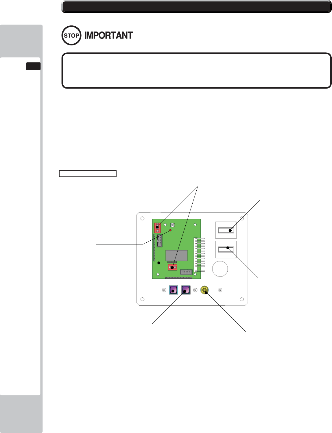
88
COIN HANDLING
12
This product comes equipped with a Money Controls SR3 Coin Acceptor. To adjust the price of play ALL
credit setting are adjusted via the EXCEL CREDIT BOARD.
IMPORTANT!
The CREDIT SETTINGS within the SYSTEM TEST MODE must be set to 1 coin 1 credit to allow the
CREDIT BOARD to function correctly.
The VTS BD has a built in Credit Board. This is controlled by 2 DIL Switches. These allow the operator to
select the price of play, type of coin acceptor and region.
EXCEL Credit Board
12-3 ADJUSTING THE PRICE OF PLAY (EXCEL)
DIL SW3 (Regional Settings)
Adjust these switches to specify the type of Coin Acceptor used and currency.
Default = SW1&SW2 ON - SR3 in parallel mode, Sterling.
TEST BUTTON Provides access to the TEST MENU when pressed.
SERVICE BUTTON Provides a SERVICE CREDIT when pressed
Status LED Flashes when functioning.
CHANNEL 1 To Coin Acceptor (SR3 TYPE.)
DIL SW1 (credit settings) Adjust to required price of pay.
VOL CONTROL MAIN VOLUME ADJUSTMENT (FRONT SPEAKERS)
EXCEL CREDIT PCB
STATUS LED
TEST BUTTON
DIP SWITCHES
COUNTER 1
COUNTER 2
VOLUME CONTROL
SERVICE BUTTON
● The price of play is determined by the confi guration of switches located on
either an EXCEL board or VTS board. The type of board used is determined by
product location. Switch settings for both types of board remain the same.
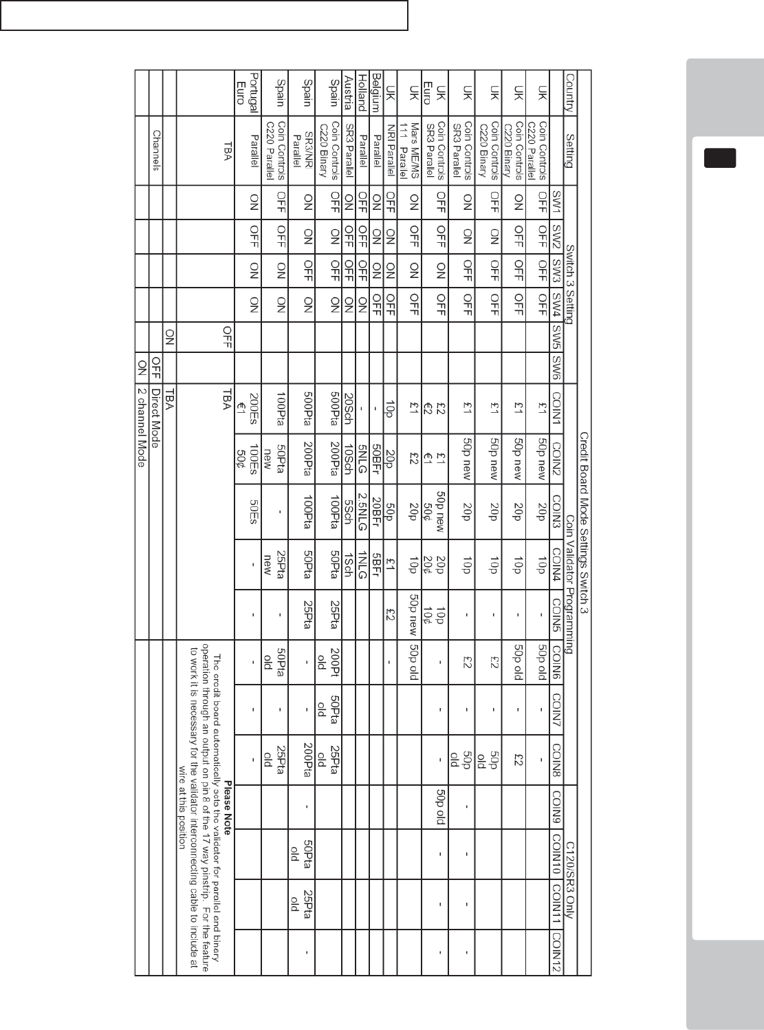
COIN HANDLING
89
12
REGIONAL AND ACCEPTOR SETTINGS (SW3)
Note: These switch settings are under constant review and may change due to world currency updates.
Set SW 1 according to the option settings found in the relevant Price of Play Settings Table on the following pages.
Set SW 3 on the VTS /Excel board as shown in the table above corresponding to the country required.
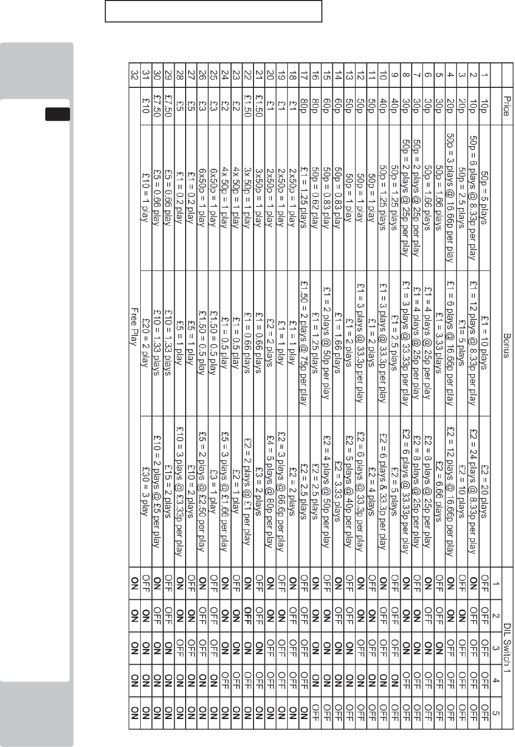
90
COIN HANDLING
12
STERLING PRICE OF PLAY SETTINGS (SW1)
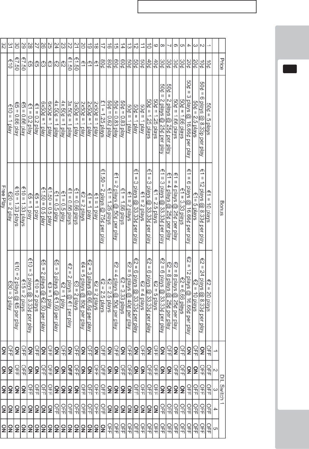
COIN HANDLING
91
12
EURO PRICE OF PLAY SETTINGS (SW1)
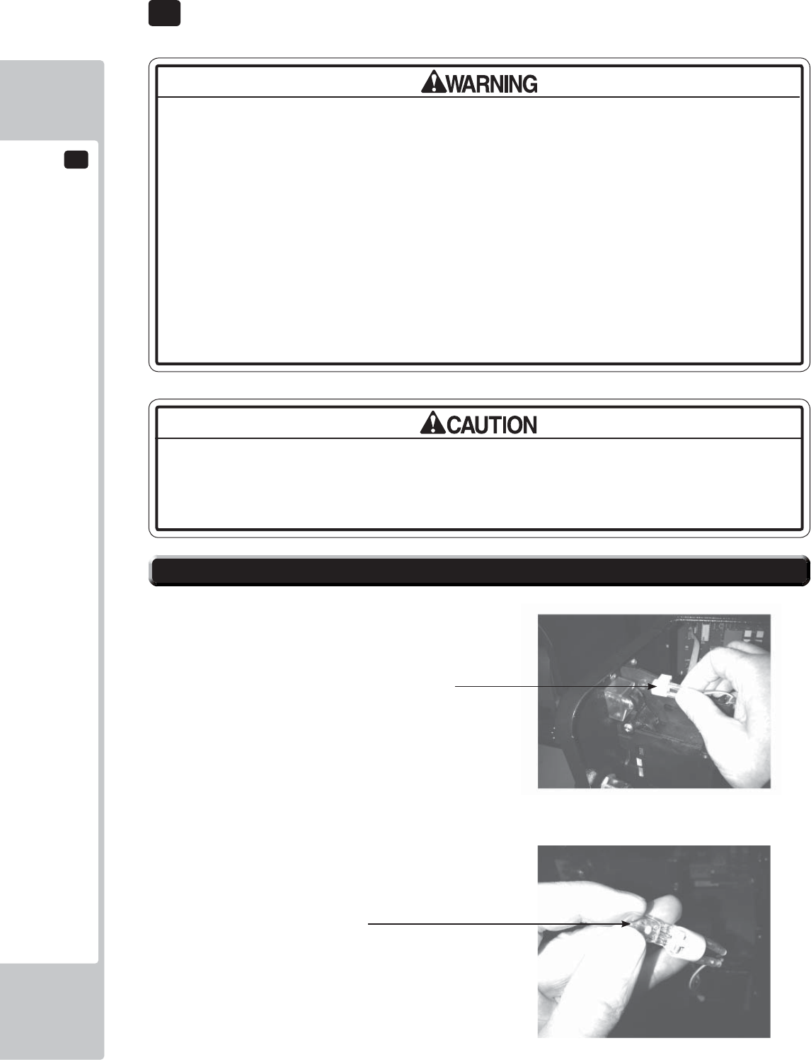
13
LAMPS AND LIGHTING
92
The Coin Door Lamp utilises a 12v 1.2w Wedge Bulb. It is important that you
replace this bulb or any other bulb of that of the same voltage and rating.
Failing to observe this caution may result in PCB failure or possible fi re hazard.
• When working with the product, be sure to turn the power off. Working with the
power on may cause an electric shock or short circuit.
• You may get burned by a hot fl uorescent lamp or other lamps. Pay full attention
to the lamps when performing the work.
• Be sure to use lamps of the designated rating. Using lamps of undesignated
rating can cause a fi re or malfunctioning.
• There is the danger of short circuits or smoke generation due to deterioration
of insulation in lighting fi xtures resulting from age deterioration. Check for
anomalies such as the following: Does it smell like something is burning? Is there
socket discoloration? Are any lamps being replaced frequently? Do lamps not
go on properly?
Step 1. Open the Coin Door and locate the Lamp Housing
directly behind the Coin Insert Bezel.
Step 2. Hold the Lamp Housing fi rmly between your index
fi nger and thumb and gently pull upwards. Do Not try
to remove the Lamp Housing whilst holding the bulb as
the bulb may break causing injury.
Step 3. Once the Lamp Housing has been removed, carefully
hold the bulb between your fi ngers and pull the Lamp
Housing away.
Do not twist either bulb or Lamp Housing whilst removing the
bulb as this may cause damage to both bulb and or Housing.
Step 4. Simply push-fi t a replacement bulb of the same type
and follow these steps in reverse to refi t.
13-1 COIN DOOR LAMP
Lamp Housing
Type: Wedge Bulb - 12v, 1.2w
13 LAMPS AND LIGHTING
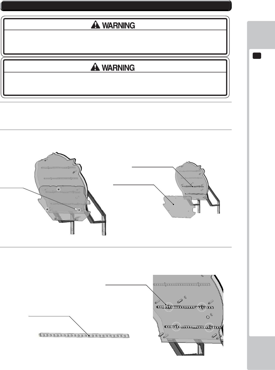
LAMPS AND LIGHTING
13
93
3
Depending on which LED strip to replace, remove the relevant cable ties which support the LED strip to the
Billboard and remove.
1
The Billboard LED’s are located between the back section of the Billboard and the front Artwork, before
attempting to change the Tube, TURN THE POWER OFF.
2
To gain access to the outer LED strips, extract the (3) M4x50 TMP BH PAS (008-B00450) fi xing screws
which hold the Billboard Title Panel in place and remove.
13-2 BILLBOARD LED LIGHTING
THIS WORK ON TOP OF THE CABINET, SHOULD NOT BE UNDERTAKEN WITHOUT THE
USE OF A SUITABLE STEP OR FOOTSTOOL.
MAKE SURE THAT THE MAIN SUPPLY VOLTAGE TO THE MACHINE IS SWITCHED OFF
AND UNPLUGGED BEFORE ATTEMPTING TO CARRY OUT THIS WORK
Title Panel
LED Strips
Fixings (3)
LED STRIP RIGID
390-2112-032WUK
Cable Ties
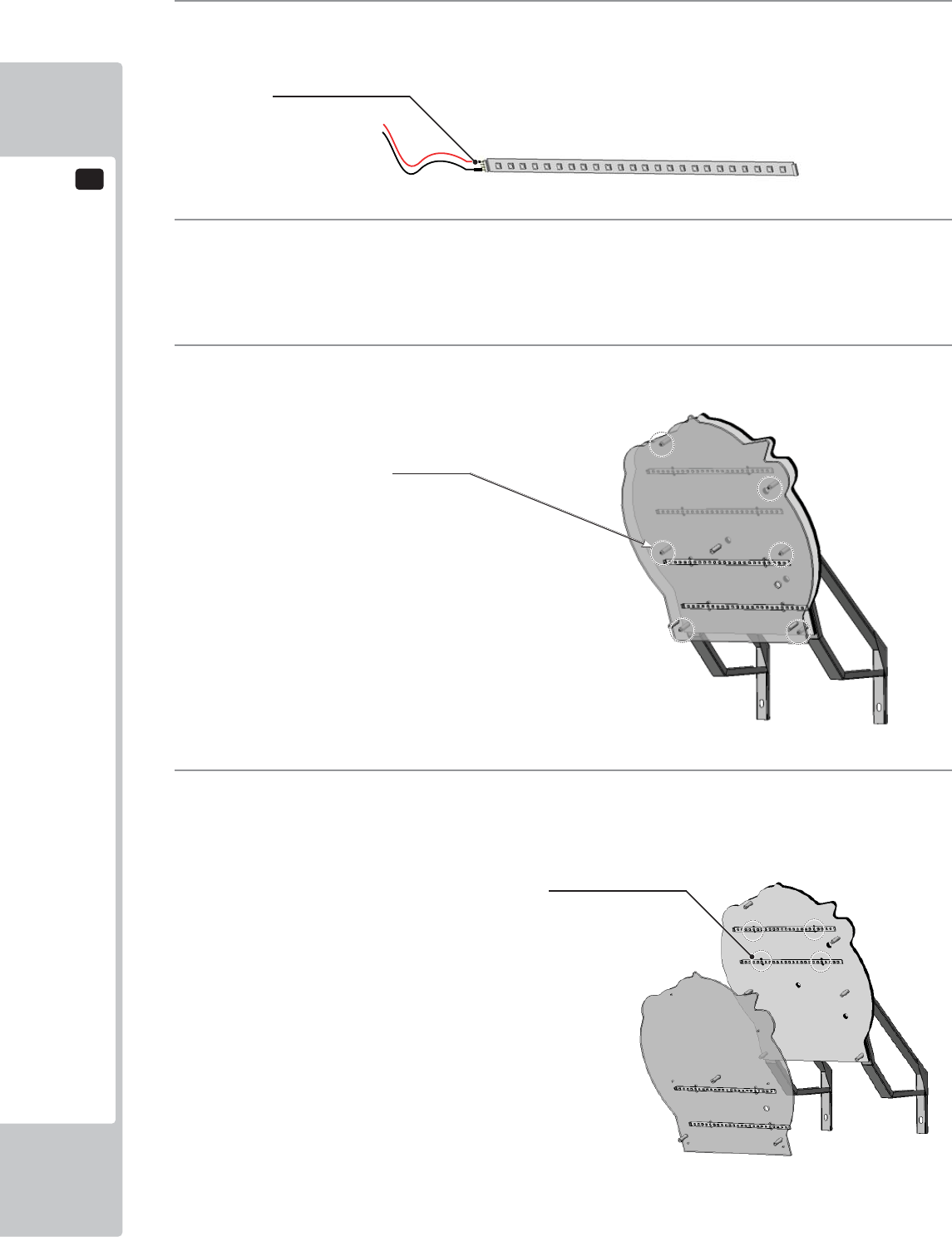
13
LAMPS AND LIGHTING
94
4
Using a sharp handled blade, carefully strip back the protective sleeving to reveal the solder joint.
Using a Soldering Iron carefully unsolder the harness from the defective LED strip.
5
Once the harness has been successfully removed from the LED strip, resolder it to the replacement LED
making note of the polarity. If the connections are reversed the LED will not light and may cause damage to
the PCB.
6
To gain access tot he inner LED strip, follow steps 1 and 2 then locate the 6 M4x50 TMP BH PAS
(008-B00450) fi xing which hold the outer Billboard in place and remove.
7
Using the same method in STEPS 3, 4 and 5 remove the defective LED strip and replace. Reassemble in
reverse order.
Fixings (6)
Cable Ties
SLEEVE
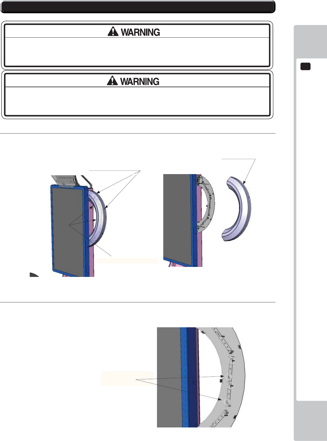
LAMPS AND LIGHTING
13
95
13-3 HALF HOOP LED LIGHTING
1
To remove the HALF HOOP Outer cover, locate and remove the (7) M4x12 SKT BH PAS (029-B00412).
Remove (4) from the outer edge and (3) from the inner edge.
2
Once the outer cover is removed, disconnect the suspected LED Bd at both ends and remove the (4) M3x16
SKT BH BLK fi xings which secure the LED Bd to the metal frame.
THIS WORK ON TOP OF THE CABINET, SHOULD NOT BE UNDERTAKEN WITHOUT THE
USE OF A SUITABLE STEP OR FOOTSTOOL.
MAKE SURE THAT THE MAIN SUPPLY VOLTAGE TO THE MACHINE IS SWITCHED
OFF BEFORE ATTEMPTING TO CARRY OUT THIS WORK
Fixing Points x (4) OUTER
(4) M3x16 SKT BH BLK
020-B00316-0B
HALF HOOP
Fixing Points x (3) INNER
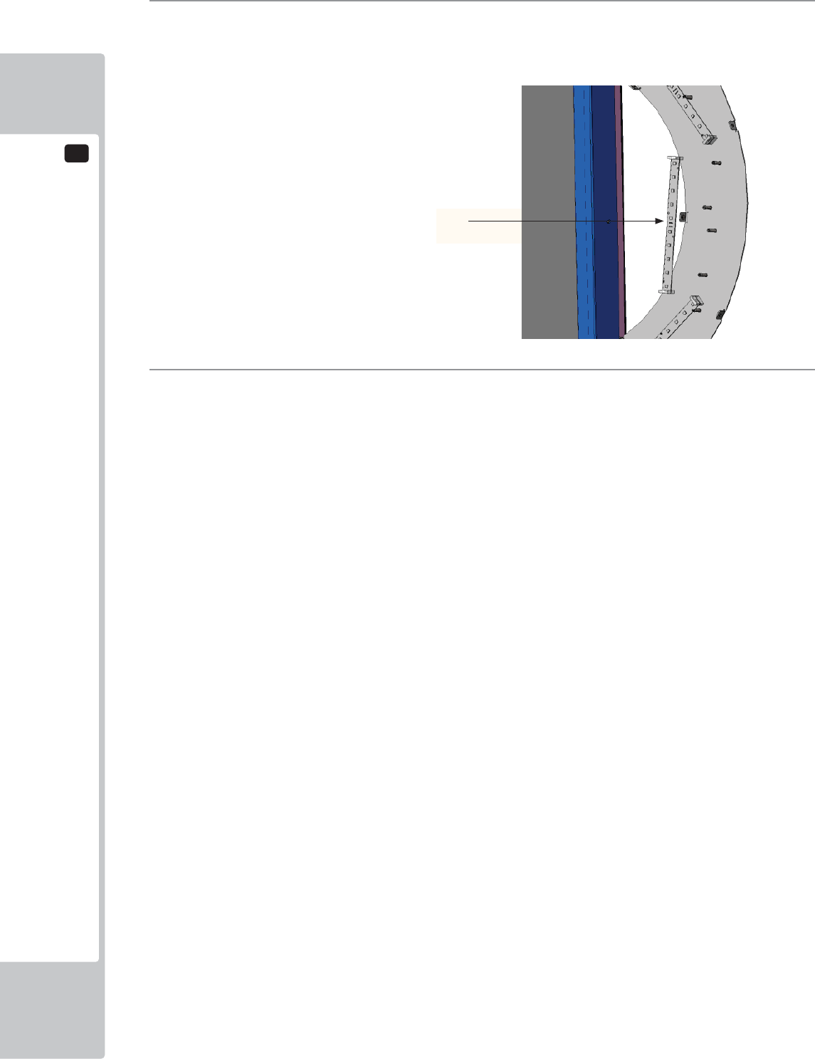
13
LAMPS AND LIGHTING
96
3
Replace the defective LED board with that of the same type. HALF RING LED BD (601-13101-001)
4
When replacing, take precautions not to overtighten. Reconnect the harnesses and refi t the Outer Ring Cover
using the fi xings removed in step 1,
Half Ring LED
601-13101-001
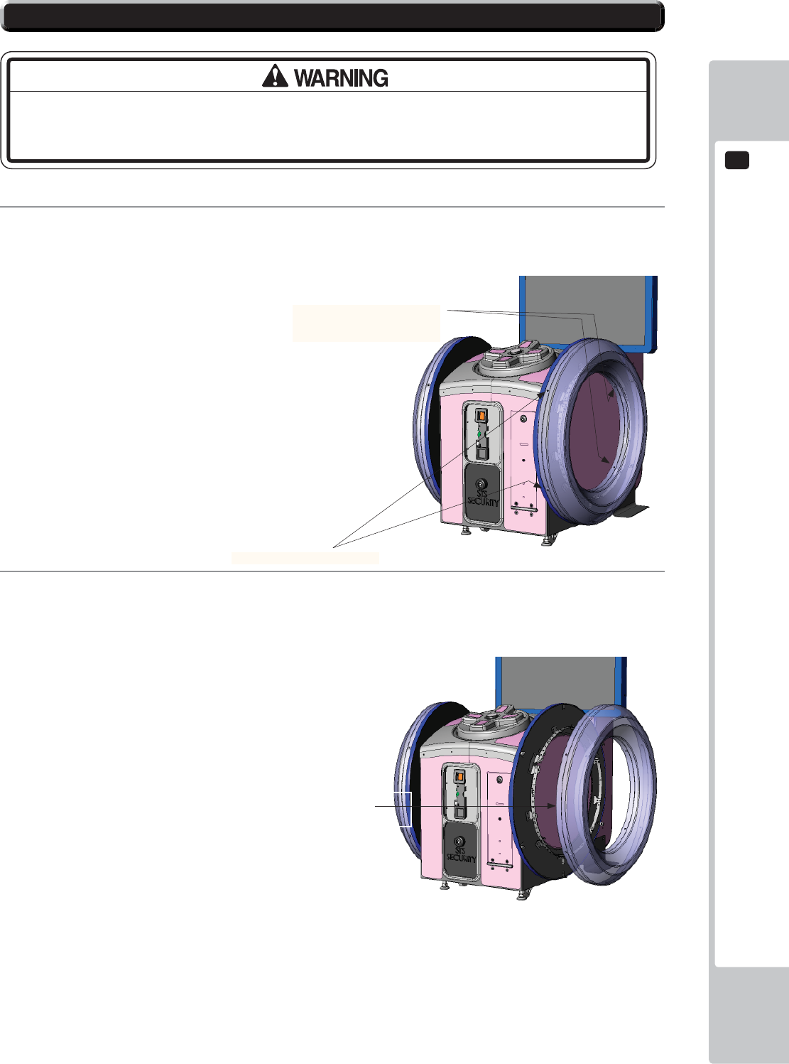
LAMPS AND LIGHTING
13
97
1
To remove the FULL HOOP Outer cover, locate and remove the (9) M4x12 SKT BH PAS (029-B00412).
Remove (5) from the outer edge and (4) from the inner edge.
2
Carefully remove the COVER SIDE RING and place fl at to one side.
13-4 FULL HOOP LED LIGHTING
MAKE SURE THAT THE MAIN SUPPLY VOLTAGE TO THE MACHINE IS SWITCHED
OFF BEFORE ATTEMPTING TO CARRY OUT THIS WORK
Fixing Points x (4) INNER
COVER SIDE RING
SND-1402-01UK
Fixing Points x (5) OUTER
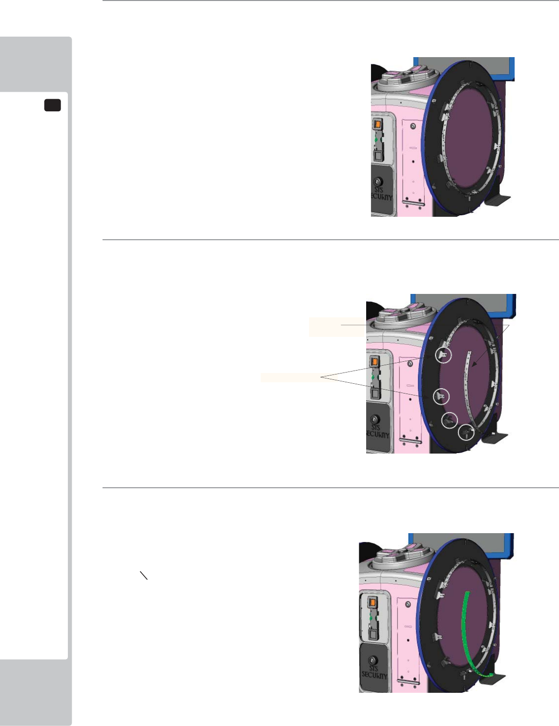
13
LAMPS AND LIGHTING
98
3
With the COVER SIDE RING removed, locate the suspect LED BD to replace and disconnect the
connectors at both ends.
4
Once the Cover has been removed and the harness disconnected, remove the (4) M3x16 SKT BH BLK
fi xings which secure the LED Bd to the metal retaining brackets.
5
Replace the suspect LED Bd with on of the same type and secure using the same fi xings from Step 4.
Reconnect at both ends and replace the COVER RING SIDE. Follow instructions in reverse order.
RING LED
601-13101-002
Fixing points (4)
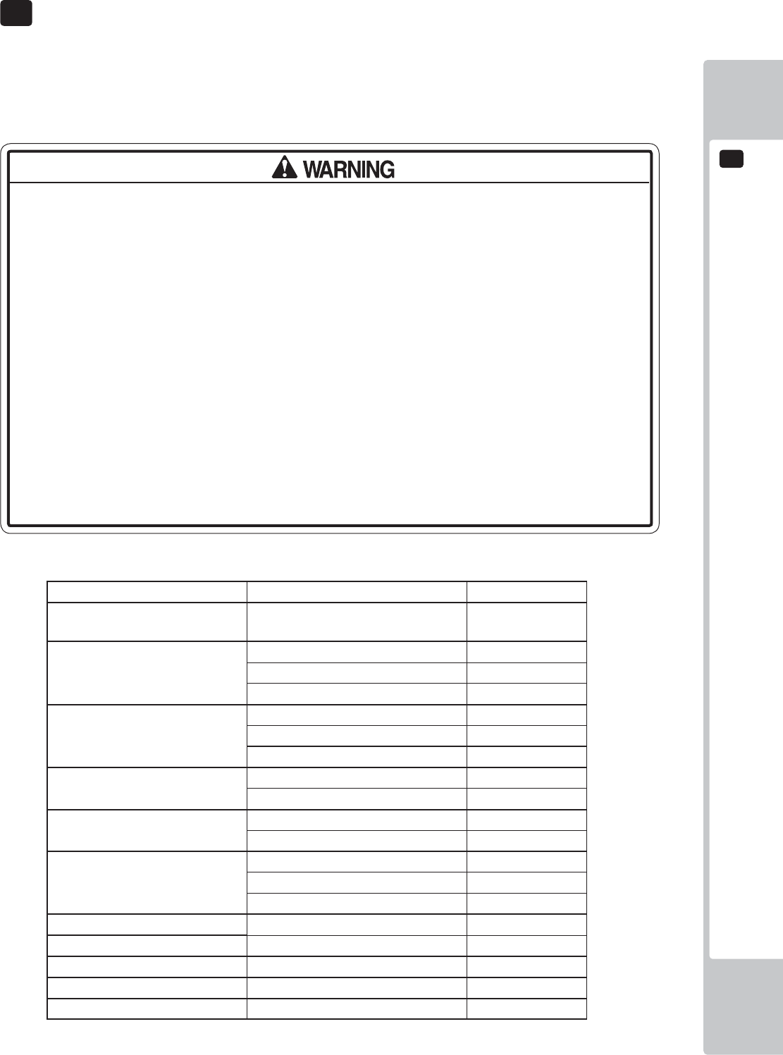
PERIODIC INSPECTION
14
99
• Every 6 months check to see if power cords are damaged, the plug is securely
inserted, dust is accumulated between the socket outlet and the power plug, etc.
Using the product with accumulated dust in the interior may cause fi re or electric
shock.
• Never use a water jet, etc. to clean the inside and outside of the cabinet. If
wetness occurs for any reason, do not use the product until it has completely
dried.
• Once a year, request the offi ce shown on this manual or the dealer from whom
the product was originally purchased to perform the internal cleaning. Using the
product with accumulated dust in the interior may cause fi re or other accidents.
Note that you are liable for the cost of cleaning the interior parts.
• There is the danger of accidents involving electrical shorts circuits or fire
caused by factors such as the deterioration of insulation in electrical and
electronic equipment over time. Check that there are no abnormalities such as
odors from burning.
The items listed below require periodic check and maintenance to retain the performance of this machine and to
ensure safe business operation.
When handling the controller, the player will be in direct contact with it. In order to always allow the player to enjoy
the game, be sure to clean it regularly. Also, it is advisable to provide wet tissue, etc. available for player use.
14 TABLE 01 PERIODIC INSPECTION TABLE
ITEMS DESCRIPTION PERIOD
CABINET Confi rm that adjusters contact
fl oor
Daily
CONTROL PANEL
CONTROLLER
Operation inspection Weekly
Cover and fi xings inspection Every 1 month
Switch and lighting inspection Every 3 months
COIN ACCEPTOR Acceptance of coins Daily
Coin Lamp Every 3 months
Cleaning Every 3 months
HALF HOOP Lighting Every 1 month
Condition Every 3 months
FULL HOOP Lighting Every 1 month
Confi rm settings Every 3 months
TICKET MECHANISM Operation Monthly
Cleaning Monthly
Sensor out Every 3 months
BILLBOARD Lighting Every 3 months
GAME BOARD Confi rm settings Monthly
POWER CABLES Inspection, Cleaning 6 months
INTERIOR Cleaning Yearly
CABINET SURFACES Cleaning As appropriate
14 PERIODIC INSPECTION
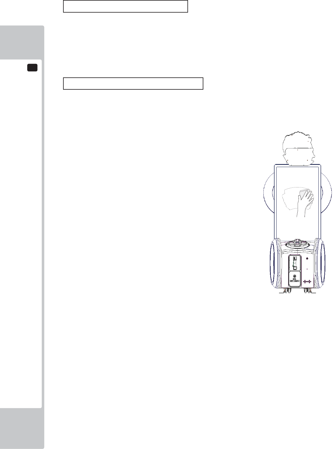
14
PERIODIC INSPECTION
100
Cleaning the Cabinet Surfaces
When the cabinet surfaces are badly soiled, remove stains with a soft cloth dipped in water or diluted (with water)
chemical detergent and squeezed dry. To avoid damaging surface fi nish, do not use such solvents as thinner, benzine,
etc. other than ethyl alcohol, or abrasives, bleaching agent and chemical dustcloth.
Some general-purpose household, kitchen and furniture cleaning products may contain strong solvents that degrade
plastic components, coatings, and print. Before using any cleaning product, read the product's cautionary notes
carefully and test the product fi rst on a small area that is not highly visible.
Screen (Cleaning)
The 55" LED Monitor is protected by a safety glass which is mounted infront of the screen. It is important that the
screen is cleaned regularly as so not to impair the players experience. It is recommended that the glass is cleaned
once a week to keep the viewing area free from marks or dust. When cleaning use a well known branded glass
cleaner.
TROUBLESHOOTING
15
101
15-1
TROUBLESHOOTING (WHEN NO ERROR MESSAGE IS SHOWN)
• In order to prevent electric shock and short circuit, be sure to turn power off
before performing work.
• Be careful so as not to damage wirings. Damaged wiring can cause electric
shock or short circuit.
• After removing the cause of the functioning of the Circuit Protector, reinstate
the Circuit Protector. Depending on the cause of the functioning, using the Circuit
Protector as is without removing the cause can cause generation of heat and fi re
hazard.
• In the event that a problem cannot be resolved by employing the procedures
listed in this Manual, be sure to request service from the office shown on this
Manual or the dealer from whom the product was originally purchased. Attempts
to employ procedures other than those specified in this Manual can cause
electrical shock, shorting, or fi re.
• In the event of a problem that is not described here, be sure to contact the
offi ce shown on this Manual or the dealer from whom the product was originally
purchased. Careless attempts at repair can result in electrical shock, shorting, or
fi re.
If a problem occurs, fi rst check to make sure that the wiring connectors are properly connected.
15 TABLE 01
PROBLEM CAUSE COUNTERMEASURES
When the main SW is
turned ON, the machine
is not activated.
The power is not ON. Firmly insert the plug into the outlet.
Incorrect power source/voltage. Make sure that the power supply/voltage
are correct.
The Fuse on the AC Unit has blown
due to momentary over current.
After eliminating the cause of overload,
replace the specifi ed rating fuse.
The fuse of the connect board has
blown due to momentary over
current.
After eliminating the cause of overload,
replace the specifi ed rating fuse.
15 TROUBLESHOOTING
15
TROUBLESHOOTING
102
Sound is not emitted. Sound volume adjustment is not
correct
Adjust the Switch Unit’s sound
adjustment volume.
Faulty connections for various
connectors
Check the connections for the game
board, amp, speakers and Volume
connectors
Malfunctioning BD, amp and speaker Perform Sound Test.
Sounds are emitted and
the lamps are lit, but the
screen is black.
Faulty connections for the visual
signal connector or the monitor power
connector
Check the connections for the monitor
and game board connectors.
Faulty LCD Display See Chapter 11
Colors on the monitor
screen are strange.
Faulty connection for the visual signal
connector.
Check the visual signal connector
connection and make sure it is secured
properly.
Screen adjustment is not appropriate. Make adjustment appropriately.
The on-screen image
sways and/or shrinks.
The power source and voltage are no
correct.
Make sure that the power supply and
voltage are correct.
Does not accept input
from any switch or
volume.
Faulty connector connections. Check the connection for the I/O Board
and Cabinet connector.
Check the power for the I/O Board.
No LED lighting from
HOOPS or HALF
HOOPS
Faulty connector connections. Check the connection for the I/O Board
and Cabinet connector.
Check the power for the I/O Board.
Faulty PSU Check for Power LED indicator on PSU.
No Ticket output Faulty connector connections. Check the connections for the connectors
between the I/O Board and Ticket
Dispenser.
No Motor drive Check for Power LED indicator on PSU.
Motor drives but no Tickets
dispensed.
Check feed of tickets within Ticket
dispenser.
Game will not start Faulty connections Check connections to and from the
Controller and I/O Bd.
Check Connections at Switch.
TROUBLESHOOTING
15
103
• In case fuse replacements other than those stated in this manual are
necessary, contact where you purchased the product from for inquiries regarding
this matter.
• In order to prevent an electric shock, be sure to turn power off and unplug
from the socket outlet before performing work by touching the internal parts of the
product.
• Be careful so as not to damage wirings. Damaged wiring can cause electric
shock and short circuit accidents.
• Be sure to use fuses meeting specified rating. Using fuses exceeding the
specifi ed rating can cause fi re and electric shock accidents.
• After eliminating the cause of the blowing of fuse, replace the fuse. Depending
on the cause of fuse blowing, continued use with the fuse as is blown can cause
generation of heat and fi re hazard.
Replacing Fuses
Fuses are located on the following:
SND-1080UK Assy AC Unit (1) 3.15 Time Delay 20mm
(1) 3.15 Time Delay 20mm (Spare)
838-14551-02UK AC Distribution PCB (2) 6.3A Time Delay 20mm
104
GAME BOARD
16
● When working with the product, be sure to turn the power off. Working with the
power on may cause an electric shock or short circuit.
● Be careful not to damage the wires. Damaged wires may cause an electric
shock, short circuit or present a risk of fi re.
● Do not use this product with connectors other than those that were connected
and used with the game board at the time of shipping. Do not carelessly connect
wires to connectors that were not used at the time of shipping, as this may cause
overheating, smoke or fi re damage.
In this product, setting changes are made during the test mode. The game board
need not be operated. Use the game board, etc. as is with the same setting made
at the time of shipment so as not to cause electric shock and malfunctioning.
Static electricity from your body may damage some electronics devices
on the IC board. Before handling the IC board, touch a grounded metallic
surface so that the static electricity can be discharged.
16 GAME BOARD (NuSX)
GAME BOARD
105
16
16-1 HANDLING PRECAUTIONS
● To prevent electric shock or IC Board malfunctioning, be sure to turn off the
power for the cabinet when installing or removing the IC Board.
● Extraneous matter such as dust on the IC Board can cause the IC Board to
generate heat and result in a fi re due to short circuit, etc. Ensure the IC Board
surfaces are always kept clean.
● Always follow the usage conditions from SEGA as well as the usage conditions
for the cabinet you are using for NuSX. Failure to do so may cause an
overheating and fi re.
● Be sure to connect the IC Board and connectors completely. Insuffi cient
insertion can damage IC Board, etc.
● For the IC Board circuit inspection, only the use of Logic Tester is permitted. The
use of ordinary testers is not permitted as these can damage the IC Board.
● Do not subject the IC Board to static electricity when installing the IC Board in
the cabinet or when connecting wire harness connectors to the IC Board.
● When soldering buttons, etc. to the wire harnesses, be sure to remove the wire
harnesses from the IC Board so as not to subject the IC Board to heat.
● Some parts are the ones designed and manufactured not specifi cally for this
product. The manufacturers may discontinue, or change the specifi cations of,
such general-purpose parts. If this is the case, SEGA cannot repair or replace a
failed product whether or not a warranty period has expired.
• It is important that the NuSX Game Bd is cleaned free from dust regularly.
If dust accumulates within the NuSX Game bd, the Game bd may
malfunction.
• If any components are removed during cleaning be sure to reconnect
them in the same manner as they were removed. Ill fitted components
may malfunction, become faulty or may possibly cause a fi re hazard.
• If you are unsure about refi tting components then please contact the point
of sale to arrange for a return or replacement NuSX Game Bd.
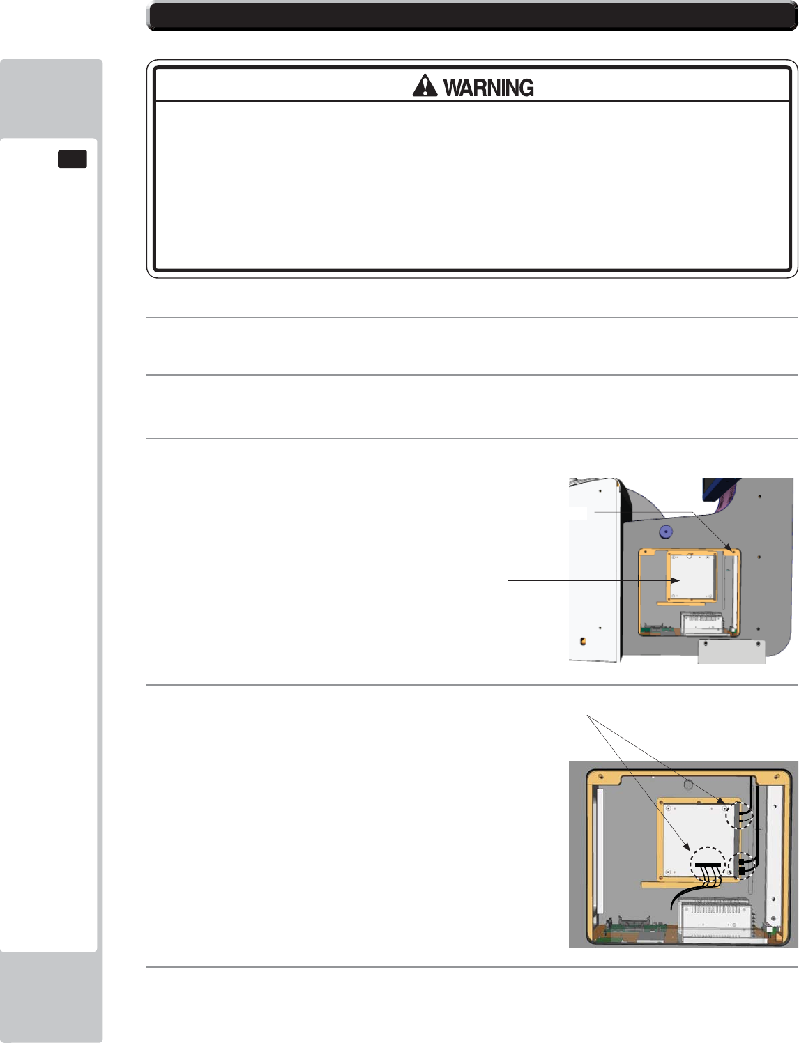
106
GAME BOARD
16
16-2 GAME BOARD (NuSX) - LOCATION
● When returning the game board after making repairs or replacements,
make sure that there are no errors in the connection of connectors. Erroneous
connections can lead to electrical shock, short circuits or fi res.
● When connecting a connector, check the direction carefully. Connectors must
be connected in only one direction. If indiscriminate loads are applied in making
connections, the connector or its terminal fi xtures could be damaged, resulting in
electrical shock, short circuits or fi res.
The NuSX Game Bd is fi tted at the rear of the cabinet and mounted to the inside RH cheek.
1
Remove the power from the machine and disconnect the Power lead.
2
Remove the (2) fi xings from the upper corners of the door. Unlock and remove the door using the key
(supplied)
3
The NuSX is located directly inside mounted to the inside wall of the cabinet.
4
Disconnect the Video, Audio, USB and COM 2 harnesses from the NuSX Game Bd..
5
Locate the (6) M4 fi xings positioned on the outer edges of the wooden mount. Unscrew and remove. The
Game board can now be removed from the cabinet.
Fixing locations
NuSX Game Bd
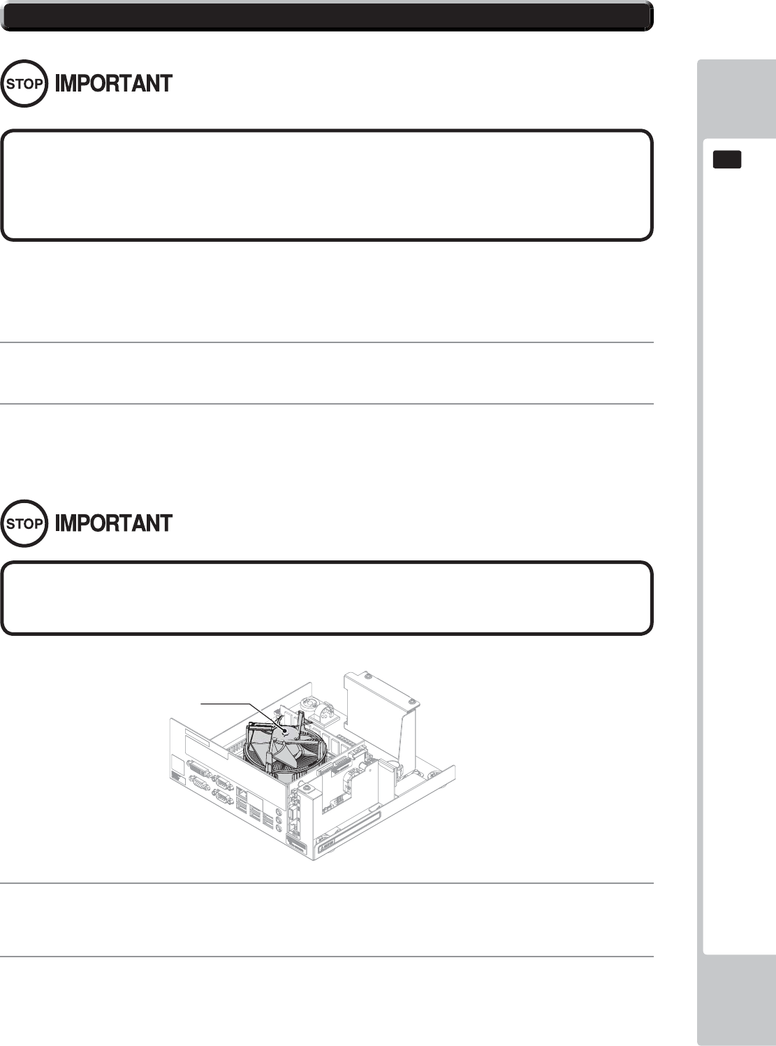
GAME BOARD
107
16
16-3 NuSX CLEANING
• If either ERROR 0090 or ERROR0091 are displayed then the Game bd must
be cleaned and made free from dust particles. These ERRORs have been
put in place to prevent the Game bd from overheating in not cleaned on
a regularly basis.
It is important that once a year the CPU cooling fan is cleaned and made free from dust. Please refer to section 16-2
for the NuSX removal procedure.
1
Refer to section 16-2 of this manual for removal of the NuSX Game Bd procedure.
3
Also clean any accumulated dust from within the CASE using an aerosol air cleaner. Take care not to
damage parts.
4
By referring to section 16-2 and following it in reverse order, please attach the NuSX to the cabinet.
2
Use an aerosol air spray to remove the dust which has accumulated in and around the CPU cooler. Once
completed use a small vacuum cleaner to suck up any loose dust particles and to clean out the Cooler fan.
The fan blade will rotate when using a Vacuum cleaner to clean it. Using your fi nger, press down lightly
upon the centre of the fan to prevent it from rotating.
CPU COOLER
Please be aware as not to damage the CPU COOLER blades or housing. These
parts are delicate and can damage easily. Take care when cleaning.
108
GAME BOARD
16
16-4 REPLACING THE LITHIUM BATTERY
• All maintenance must be performed by a qualified technical. Work carried
out by any other than a qualified technician may cause the product to
malfunction, overheat or even an electric shock.
• Please remove power before commencing any work. Failure to remove power
may cause an electric shock, short circuit or fi re hazard.
• Take care when working within the NuSX case as not to damage the IC Board
or its component and harnessing. Damaging any of these parts may cause
and electric shock, short circuit or fi re hazard.
• Please adhere to the following when handling batteries:-
-Never try to charge or apply any voltage to the battery with the purpose in
which to charge.
-Never try to disassemble the battery.
-Do not apply heat to the battery or store it near a heat source.
-Do not dispose of a battery within a fi re or try to incinerate.
-Do not dispose of batteries along with normal household waste.
• Please do not carry out any repairs/maintenance not described within this
manual. Carrying out repairs/maintenance outside this manual may result in
electric shock, short circuit or fi re hazard.
• When Power is fi rst applied after maintenance, please be aware of the state
of the CPU and other electronic components. If anything outside the normal
operation occurs be ready to remove power.
• Please take care when reconnect harnesses. Make sure connectors are fi rmly
connected. If damage occurs during reconnecting then please contact your
local SEGA offi ce for replacement.
GAME BOARD
109
16
● Make sure you do not damage the printed board and wires. Such damage can
lead to electric shock, short circuit and fi re hazard.
● To prevent overheating, explosion, or fi re:
- Do not recharge, disassemble, heat, incinerate, or short the battery.
- Do not allow the battery to come into direct contact with metallic objects or
other batteries.
- To preserve the battery, wrap it in tape or other insulating material.
● Follow local regulations when disposing of the battery. Improper disposal can
damage the environment.
● Even the site maintenance personnel or other qualifi ed professionals must not
perform replacement operations for parts not described in this manual. In the
event that such work is required either contact the offi ce listed in this manual or
fi rst confi rm the procedure with the place or offi ce of purchase. Failure to do so
may lead to electric shock or short circuit.
● Do not turn on the power with current carrying parts exposed. Doing so could
result in electric shock or short circuit.
● The batteries in NuSX can be used for approximately 5 years of standard usage.
If the battery appears to require replacement sooner than 5 years it is more
likely that an error has occurred with some other part of the board. Rather
than exchanging the battery requesting repair of the board itself may be more
appropriate.
● Static electricity from your body may damage some electronics devices on the
IC board. Before handling the IC board, touch a grounded metallic surface so
that the static electricity can be discharged.
To avoid risk of malfunction and damage:
- Make sure the positive and negative ends are aligned correctly.
- Use only batteries approved for use with this unit.
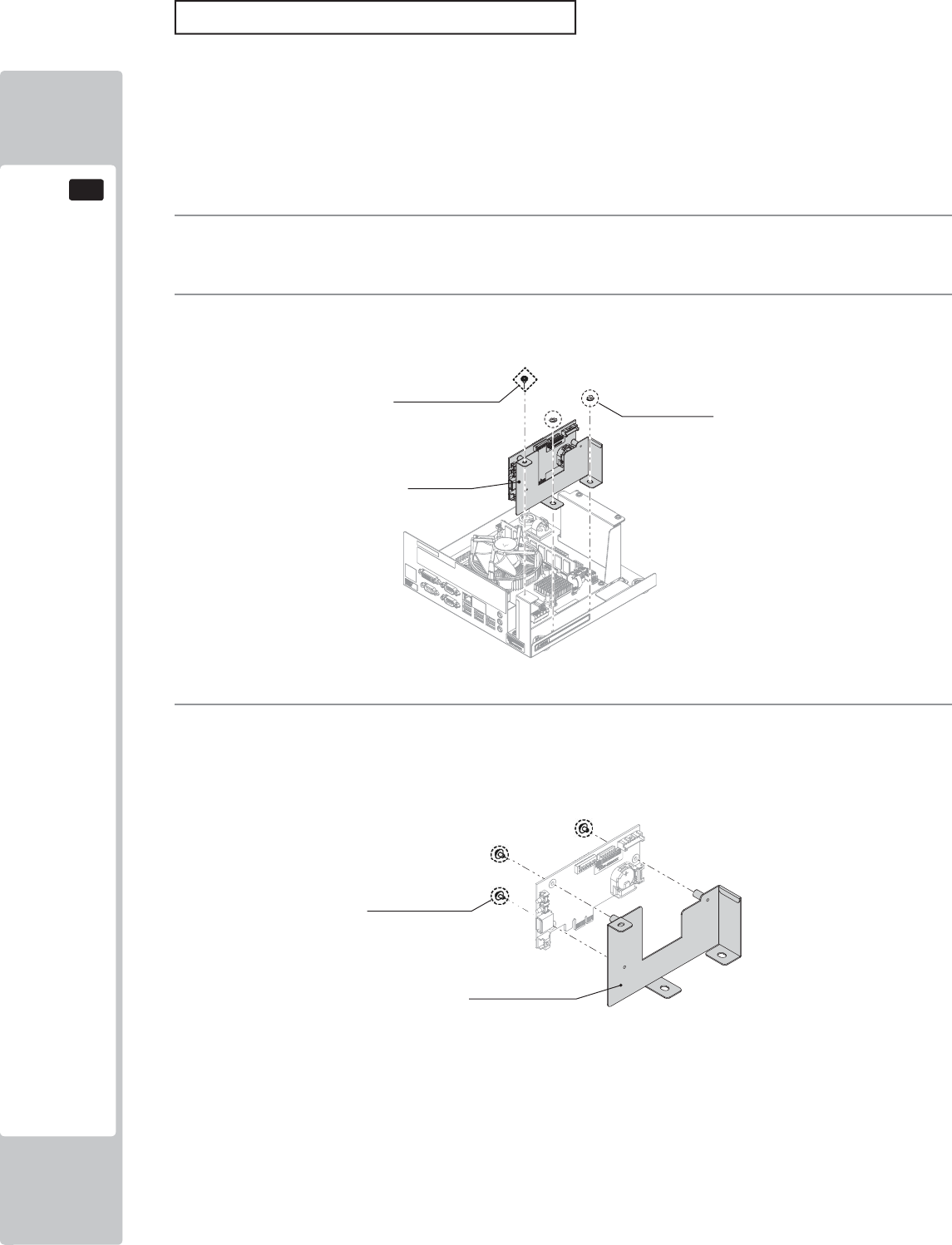
110
GAME BOARD
16
AM EXPANSION BOARD
1
Please refer to section 16-2 of this manual for instructions on safely removing the NuSX Bd from the
cabinet.
3
Once the Expansion Bd is removed from the NuSX. Unscrew and remove the (3) M3x6 Machine screws
which secure the Expansion Bd to the Expansion Bd Brkt.
2
To remove the Expansion Bd, unscrew the single M3 machine screw and the (2) M4 fl ange nuts.
Only replace the battery when prompted by the displayed error. Do not perform this task otherwise.
The battery within the AM Expansion Board has a life span of approximately 5 years of normal use. After 5 years
normal operation the AM Expansion Bd may no loger be able to save the backup data. Please replace the battery
within this time.
If within the 5 years of normal operation the battery needs replacing, please contact your local Sega Service centre
as it may be considered that some abnormalities may have occured within the Game Bd.
AM Expansion Bd
(1) Screw
M3 × 6, flat, spring wshr (2) Flang Nuts
M4
(3) Screws
M3 × 6、Flat Spring Wshr
AM Expansion Bd Bkt
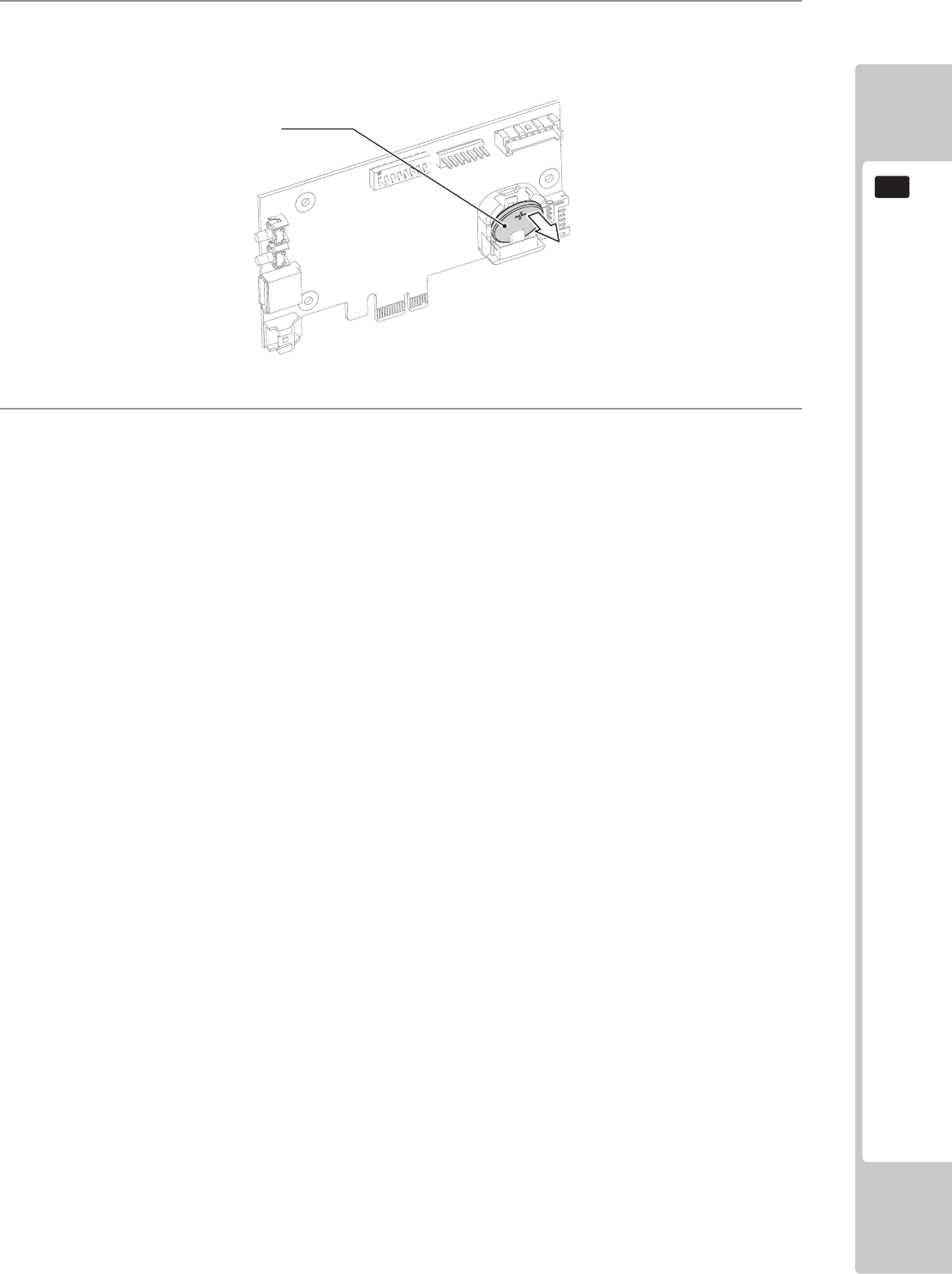
GAME BOARD
111
16
4
To remove the battery from the Expansion Bd, using your fi nger nad thumb, lift up the battery to enable you
to grasp it from the top. Take note of the battery orientation. The (+) positive is facing outside.
5
After the new battery has been replaced, please refer to these instructions and apply them in reverse order to
reassemble.
Lithium Battery
401-0054
y
y
y
y
40
1-
00
5
4
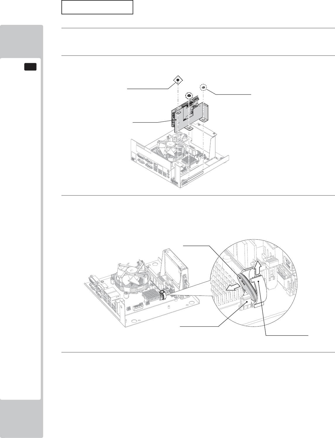
112
GAME BOARD
16
MAIN BOARD
1
Please refer to section 16-2 of this manual for instructions on safely removing the NuSX Bd from the
cabinet.
2
Remove the Expansion Bd, unscrew the single M3 machine screw and the (2) M4 fl ange nuts.
3
To replace the battery on the MAIN BD. Pull up the lock on the battery holder and remove the Lithium
battery. It is important that the Lithium battery is replaced immediately. If a time of 100 seconds or more
lapses then it is possible that a CMOS Checksum error may occur. You may receive an error in the display.
If is occurs then please contact your local Sega Service center as described within this manual.
4
To reassemble, follow these instructions in reverse order.
AM Expansion Bd
(1) Screw
M3 × 6, flat, spring wshr (2) Flang Nuts
M4
Lithium Battery
401-0054
y
y
4
0
1-
00
5
4
Jumper Socket
Battery holder lock
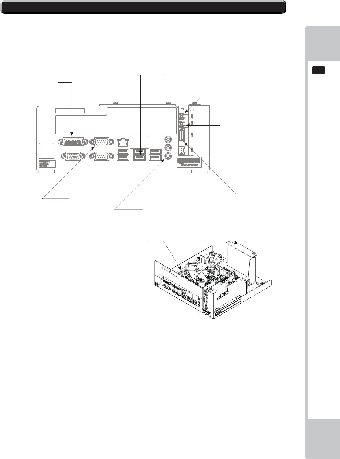
GAME BOARD
113
16
16-5 NuSX CONNECTIONS
The NuSX GAme Bd has various connections which are required by this game and therefore need to be connected
for the game to function correctly.
Any other connection made to the NuSX which are not highlighted in this section shoul d not be made.
DO NOT connects phone chargers or any other auxillary electronic item into the unused USB posts. Connection
items such as chargers will cause an over current power demand which can result in malfunction or even fire
hazzard.
PWR INPUT
Sw1
Test Switch
Sw2
Service Switch
JVS
USB to JVS I/O Bd
Audio Out
3.5mm Jack to Audio Amp
COM 2
LED Controller
DVI
Video Output
USB
Security Key Chip
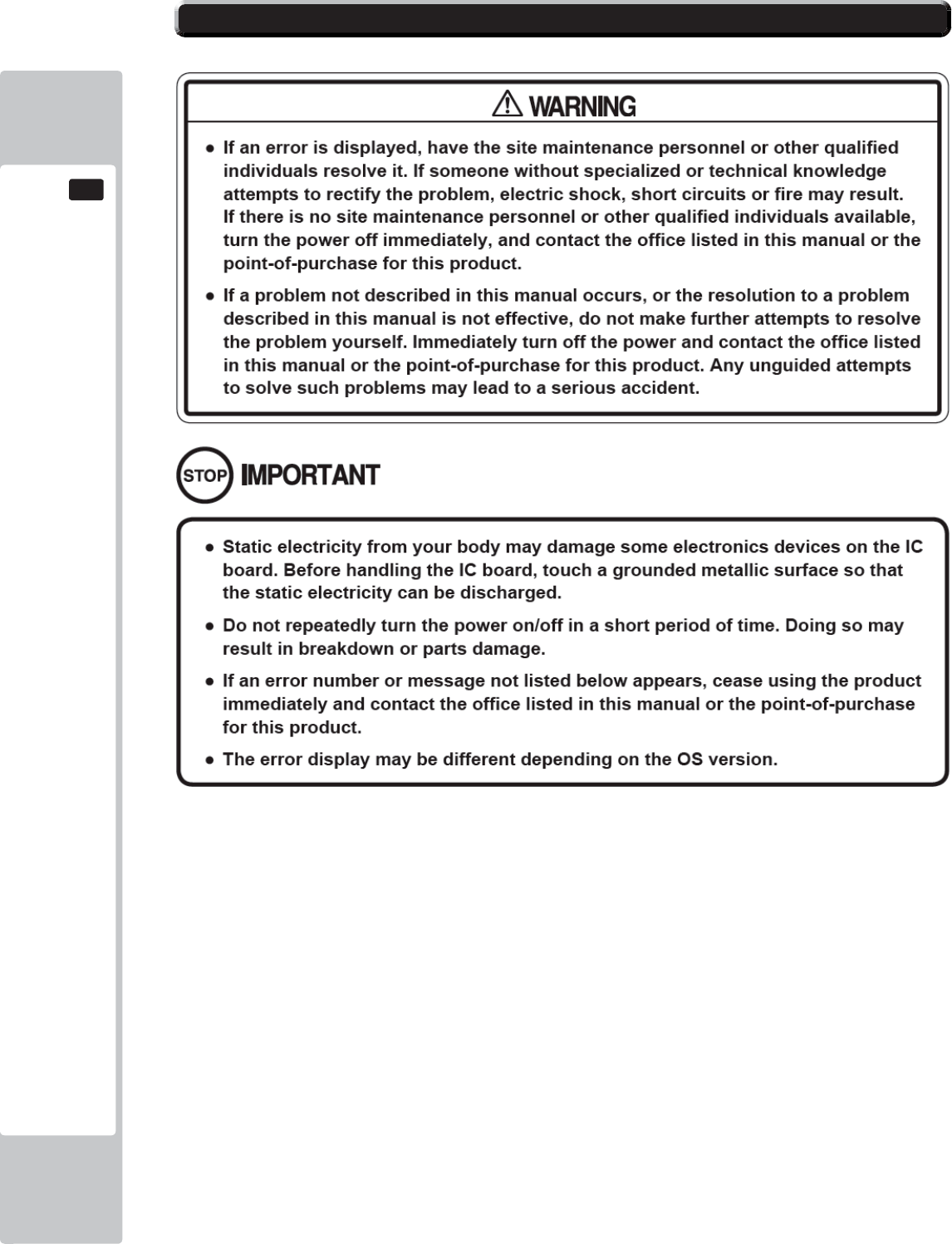
114
GAME BOARD
16
16-6 ERROR CODES
The NuSX is equipped to display various errors on-screen to help solve any problems. If an error is displayed, the
game cannot be used. Use the following table of causes and countermeasures to solve the problem.
If the problem cannot be resolved, contact the offi ce listed inthe manual or the Point-of-purchase.
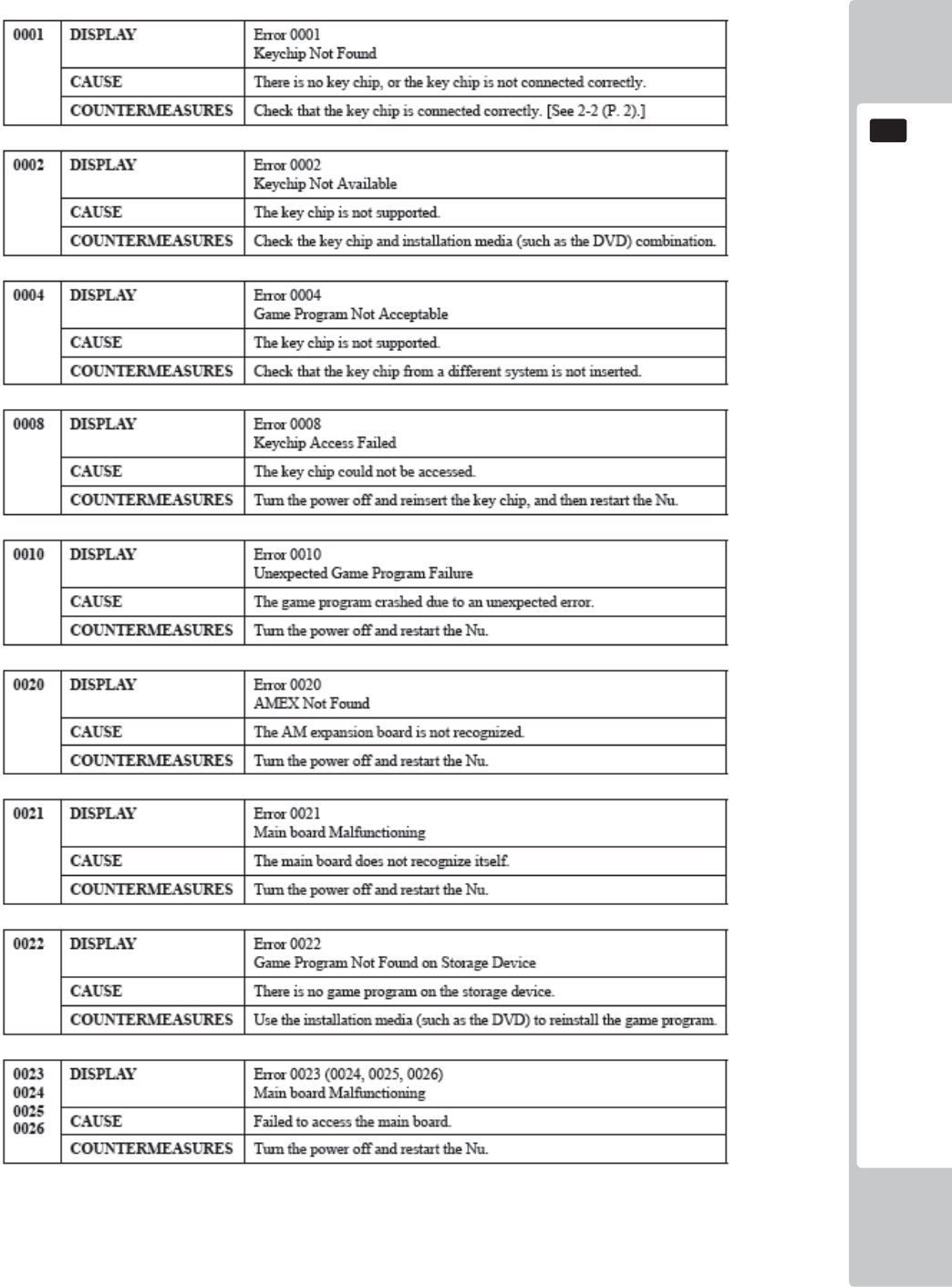
GAME BOARD
115
16
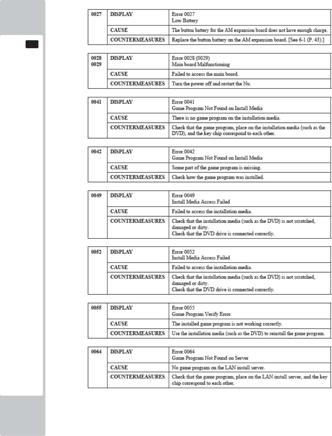
116
GAME BOARD
16
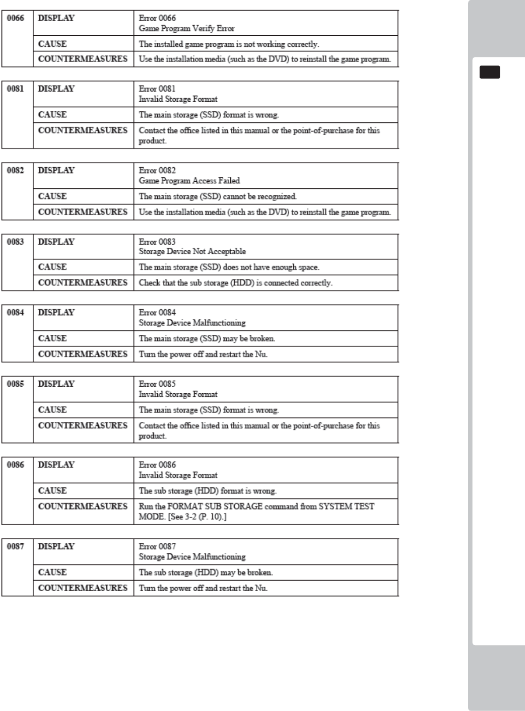
GAME BOARD
117
16
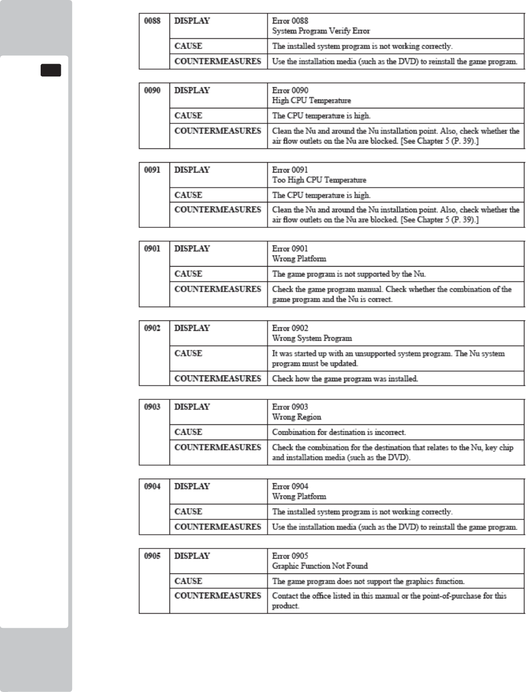
118
GAME BOARD
16
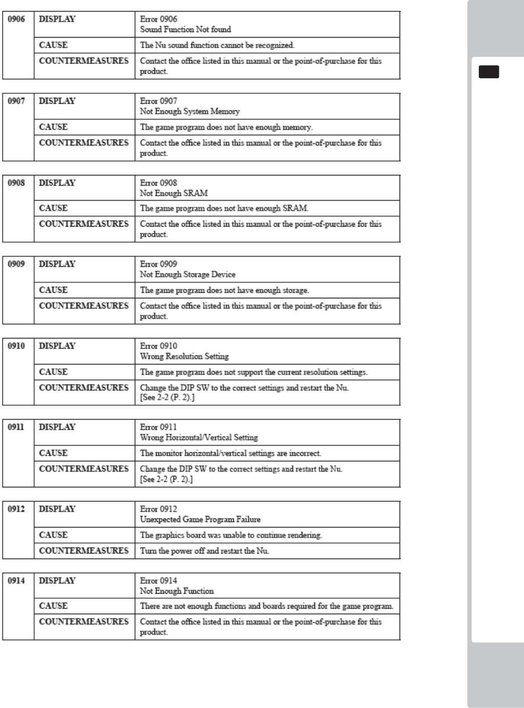
GAME BOARD
119
16
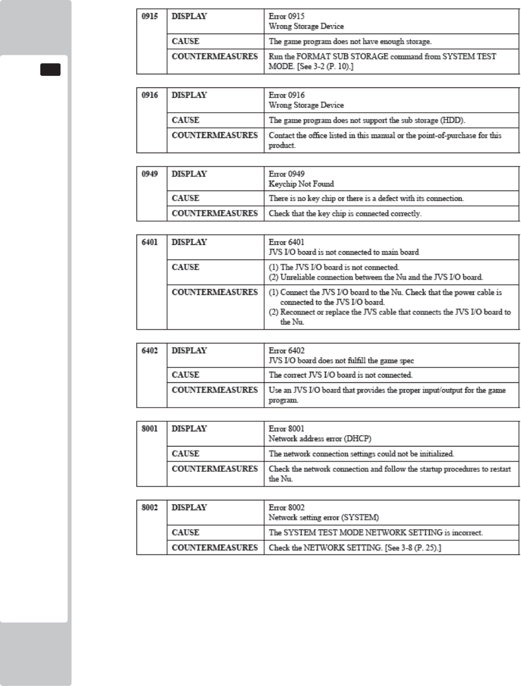
120
GAME BOARD
16
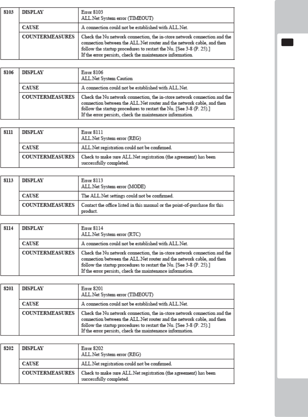
GAME BOARD
121
16
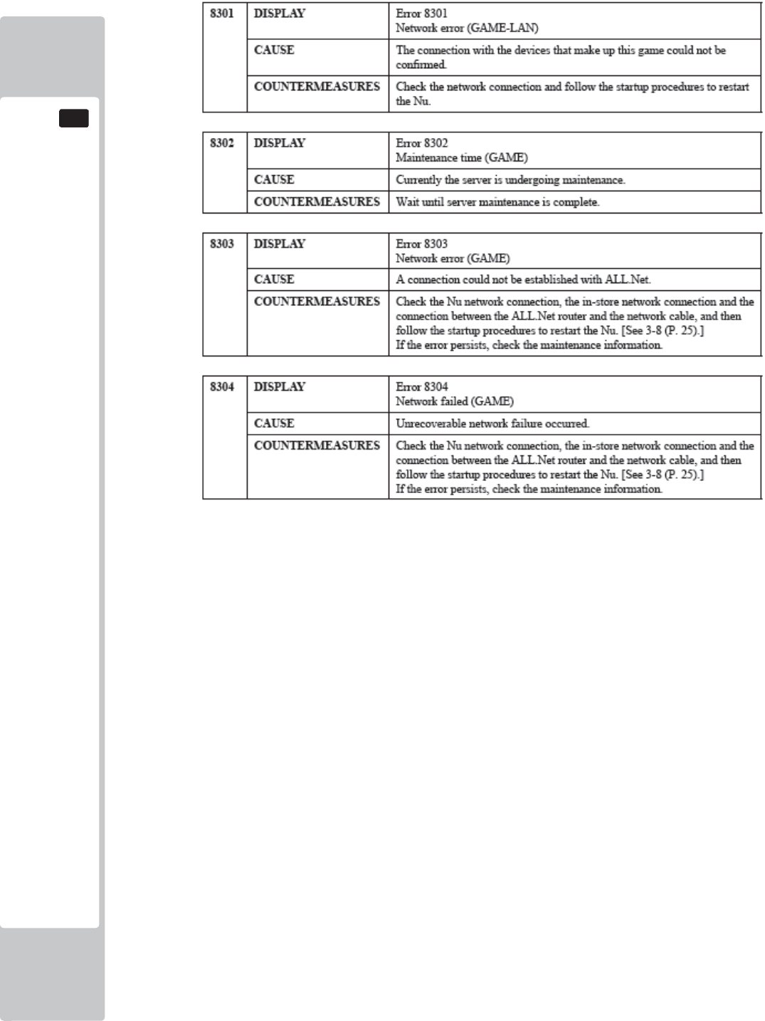
122
GAME BOARD
16
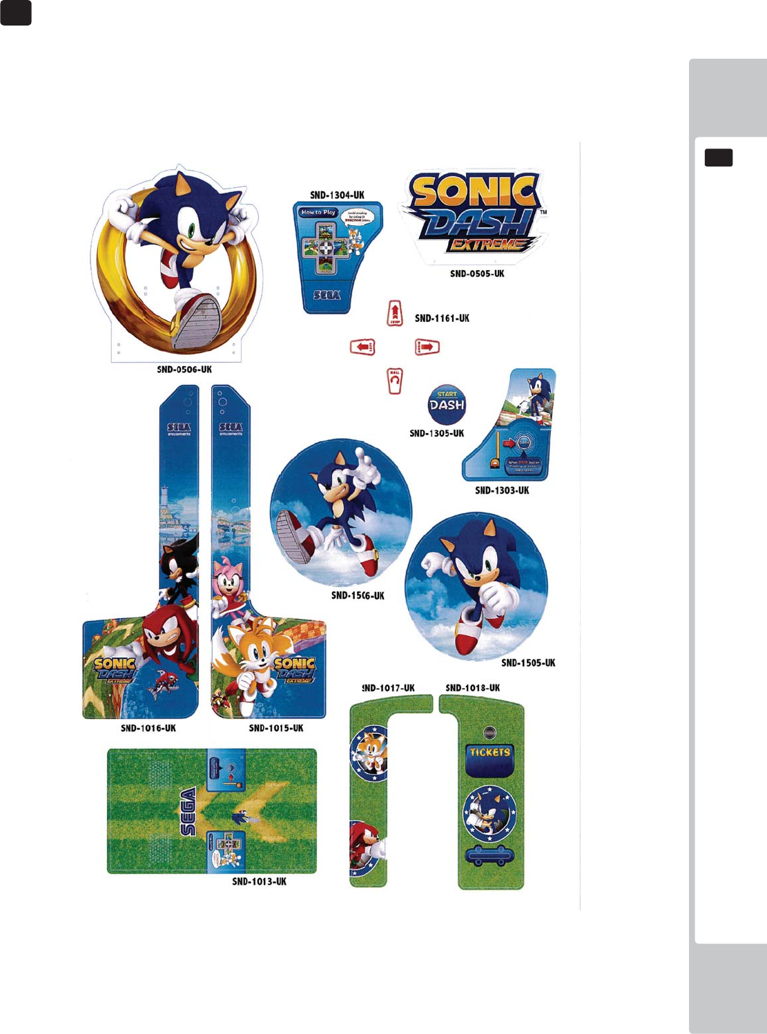
DESIGN - RELATED PARTS
123
17
17
For the warning display stickers, refer to Section 1.
17 DESIGN RELATED PARTS
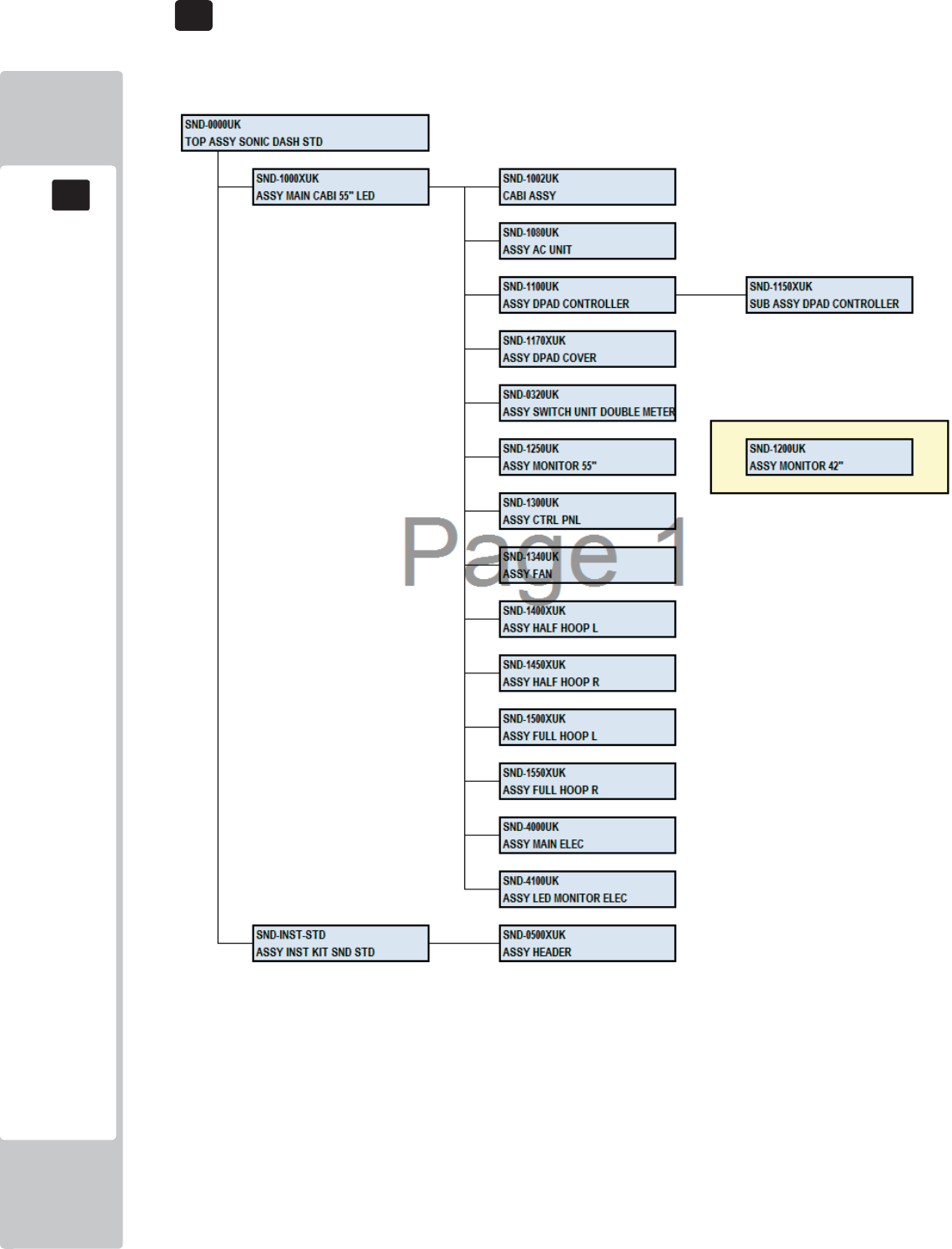
PARTS LIST
18
18
124
ASSY TOP SONIC DASH STRUCTURE
18 PARTS LIST
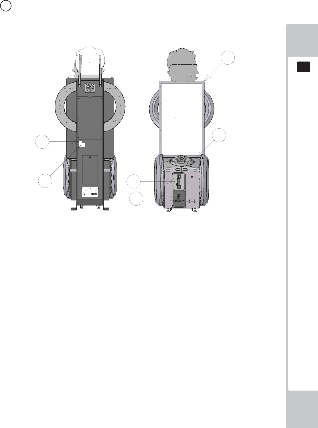
PARTS LIST
18
18
125
1 ASSY TOP SONIC DASH (SND-0000UK) (D-1/1)
ITEM PART NUMBER DESCRIPTION QTY
*1 SND-1000XUK ASSY MAIN CABI 55" LED 1
*20 421-7988-91UK STICKER SERIAL NUMBER UK 2
*21 440-WS0100UK LABEL WARNING FORK HERE 4
*22 440-DS0010UK LABEL DANGER HI VOLT 5
*23 LB1046 LABEL TESTED FOR ELEC. SAFETY 1
*24 LB1130 LABEL WEEE WHEELIE BIN 1
*25 440-CS0186-01UK STICKER CAUTION EPILEPSY 2
*26 440-CS0010UK LABEL CAUTION GENERIC 2
*101 220-5374-01 DOOR DFMD W/FR&LOCK C120 UNIV 1
*102 220-5575UK LOCK (J9117) KEY TO LIKE 22MM W CAM 1
*103 OS1247 ALUMINIUM STICKY CLIP ASK-3 3
*105 220-5727-01B DOOR CASH H.S. STS 1
*401 SND-INST-STD ASSY INST KIT SND STD 1
*410 PK0502 PALLET SND STD 1
*411 PK0503 SHRINK WRAP SND STD 1
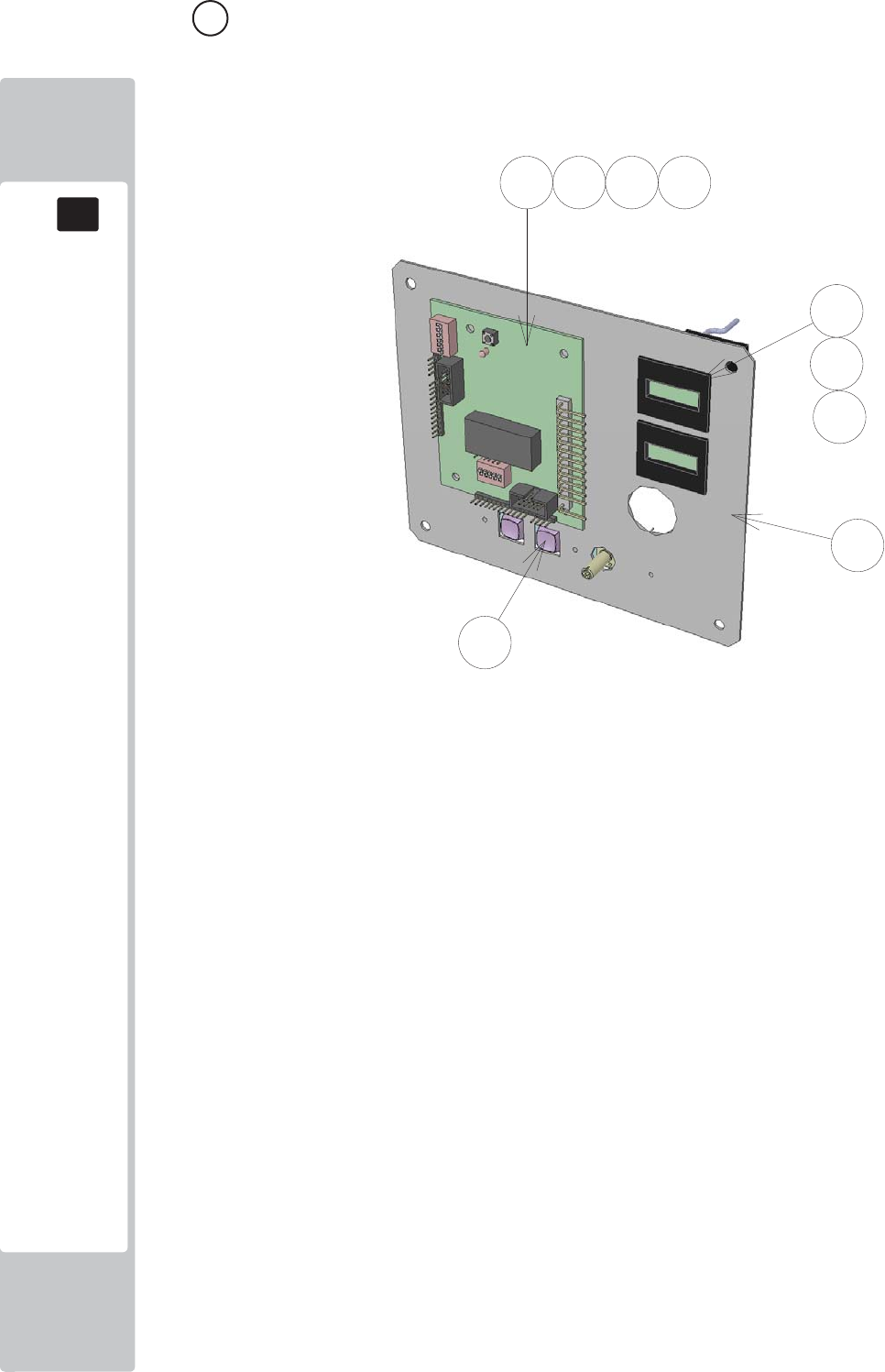
PARTS LIST
18
18
126
2 ASSY SW UNIT DOUBLE METER (SND-0302UK) (D-1/1)
ITEM PART NUMBER DESCRIPTION QTY
***1 SSR-0321UK SW BRKT DOUBLE METER 1
***2 LB1152 STICKER VTS 1
***101 838-14548-01AUK SW & VOL CTL BD 1
***102 280-L00706-PM STANDOFF 6.4MM HOLE PM 4
***103 EP1380-01 CREDIT BOARD EXCEL 1
***104 220-5643UK COIN METER SMALL 12V 2
***106 601-6231-B095 EDGE TRIM NEW TYPE 0.91t 0.1
***107 OS1098 CRIMP BELL END SMALL 4
***108 601-0460 CABLE TIE NYLON 100MM 2
***201 020-000308-0B M3X8 SKT CAP BLACK 3
***202 060-F00300-0B M3 WSHR FORM A FLT BLACK 3
***203 060-S00300-0B SPR WASHR BLK M3 3
***301 SND-60006UK WH COIN HANDLING 1
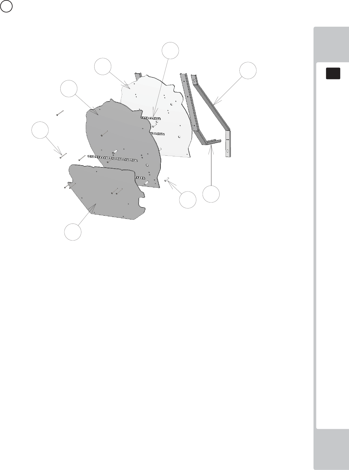
PARTS LIST
18
18
127
3 ASSY HEADER (SND-0500UK) (D-1/1)
ITEM PART NUMBER DESCRIPTION QTY
***1 SND-0511XUK BRKT SECURE HEADER REAR SUPP 2
***3 SND-0513XUK BRKT SECURE HEADER REAR 2
***5 SND-0505UK PNL HEADER FRONT 1
***6 SND-0506UK PNL HEADER REAR 1
***7 SND-0517XUK PNL HEADER BACKBOARD 1
***102 280-L01030-0S STANDOFF 10OD 5.2ID 30L 9
***103 601-0460 CABLE TIE NYLON 100MM 11
***201 050-F00400 M4 NUT FLG SER PAS 7
***202 008-B00450 M4X50 TMP BH PAS 9
***203 068-441614 M4 WSHR 16OD FLT PAS 5
***204 029-B00412 M4X12 SKT BH PAS 2
***301 SND-6001UK ASSY LED RIGID 12V WHT 320mm 1
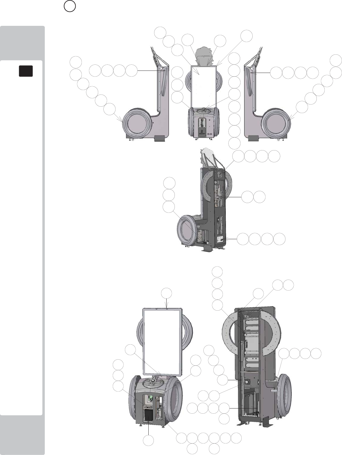
PARTS LIST
18
18
128
4 ASSY MAIN CABI (SND-1000UK) (D-1/3)

PARTS LIST
18
18
129
4 ASSY MAIN CABI (SND-1000UK) (D-2/3)
ITEM PART NUMBER DESCRIPTION QTY
**1 SND-1002UK ASSY CABINET 1
**2 SND-1100UK ASSY DPAD CONTROLLER 1
**3 SND-1250UK ASSY MONITOR 55" 1
**4 SND-1300UK ASSY CTRL PNL 1
**5 SND-1340UK ASSY FAN 1
**6 SND-1400XUK ASSY HALF HOOP L 1
**7 SND-1450XUK ASSY HALF HOOP R 1
**8 SND-1500XUK ASSY FULL HOOP L 1
**9 SND-1550XUK ASSY FULL HOOP R 1
**10 SND-4000UK ASSY MAIN ELEC 1
**11 SND-4100UK ASSY LED MONITOR ELEC 1
**12 SND-1080UK ASSY AC UNIT 1
**13 SND-0320UK ASSY SWITCH UNIT DOUBLE METER 1
**14 SND-1170XUK ASSY DPAD COVER 1
**21 SND-1003UK BRKT CHANNEL CHEEK 2
**23 SND-1005UK BRKT MON SUPP CROSS BEAM 2
**24 SND-1006UK PLATE SUPPORT HALF HOOP 2
**25 SND-1007UK SPACER FULL HOOP SUPP 2
**26 SND-1008XUK PLATE BB LIGHT MTG 1
**28 SND-0512XUK BRKT SECURE HEADER MON 2
**29 SND-1011UK BRKT MTG TICKET RELEASE BTN 1
**31 SND-1013UK SPEAKER COVER 1
**33 SND-1015UK STICKER CHEEK L 1
**34 SND-1016UK STICKER CHEEK R 1
**35 SND-1017UK STICKER FRONT L 1
**36 SND-1018UK STICKER FRONT R 1
**40 PG-1106UK HOLDER TICKET 1
**41 PG-1107UK BRKT RETAIN TICKET HOLDER 1
**42 PP1087 BOX CASH FOR MINI DOOR 1
**43 DUT-0302UK COIN PATH PLATE 1
**101 848-1001D-02 ASSY NUSX W HDD EXP 1
**102 610-0890-007BG KEY CHIP NUSX SONIC DR 1
**107 220-0001-01UK TICKET VEND UNIT TD-963CR 1
**108 130-010-04020 SPKR 4OHM 20W FR 10 HM 4898 2
**109 838-0015UK TICKET INTERFACE BOARD 1
**110 EP1820 SW MICRO LEVER RS 1
**112 280-A01264-WX ROUTER TWIST D12 SO6.4 WOOD X 25
**113 280-A02064-WX ROUTER TWIST D20 SO6.4 WOOD X 2

PARTS LIST
18
18
130
4 ASSY MAIN CABI (SND-1000UK) (D-3/3)
**201 029-B00840-0B M8X40 SKT BH BLK 12
**202 060-S00800-0B M8 WSHR SPR BLK 12
**203 068-852216-0B M8 WSHR 22OD FLT BLK 24
**204 068-652016-0B M6 WSHR 20OD FLT BLK 12
**205 050-F00600 M6 NUT FLG SER PAS 6
**206 029-B00416 M4X16 SKT BH PAS 8
**207 068-441614 M4 WSHR 16OD FLT PAS 19
**208 029-B00425-0B M4X25 SKT BH BLK 32
**209 060-S00400-0B M4 WSHR SPR BLK 13
**210 068-441614-0B M4 WSHR 16OD FLT BLK 36
**211 030-000650 M6X50 BLT PAS 8
**212 060-S00600 M6 WSHR SPR PAS 16
**213 008-B00450 M4X50 TMP BH PAS 4
**214 050-F00400 M4 NUT FLG SER PAS 4
**215 020-F00830-0B M8X30 SKT CSK BLK 10
**216 050-F00800 M8 NUT FLG SER PAS 10
**217 029-B00825-0B M8X25 SKT BH BLK 2
**218 029-B00612 M6X12 SKT BH PAS 8
**219 012-P03512-FB N6x1/2" S/TAP FLG BLK 12
**220 020-F00625-0Z M6X25 SKT CSK OZ 2
**221 000-P00420 M4X20 MSCR PAN PAS 5
**222 012-P00325 N4X1" S/TAP PAN PAS 4
**223 020-B00316-0B M3X16 SKT BH BLK 2
**224 029-B00412 M4X12 SKT BH PAS 6
**225 060-S00400 M4 WSHR SPR PAS 6
**306 SND-60007UK WH BASEBOC TO COCKPIT 1
**307 SND-60008UK WH FAN & LED 1
**308 SND-60009UK WH TICKET VEND & MICROSW 1
**311 SND-60012UK WH BUTTONS 1
**312 SND-60018UK WH SPEAKERS B 1
**314 SND-60020UK WH LED CNTRL A2 1
**315 SND-60027UK WH LED CNTRL B2 1
**317 600-7500-180UK SER CABLE 9P M/F 22-0012-04 1
**320 600-9050-44K WH EARTH 50CM M4/M4 K 1
**321 600-9150-44K WH EARTH 150CM M4/M4 K 1
**323 600-7141-100UK CABLE JVS TYPE A-B 100cm 1
**324 600-7009-2500UK ASSY RGB CA D-SUB 15 1
**325 600-7155-0180UK CA AUDIO 3.5MM JACK M/M 1.8M 628-7196 1
**326 600-9025-44K WH EARTH 250MM M4/M4 1
**327 600-9050-45K WH EARTH 500MM M4/M5 1
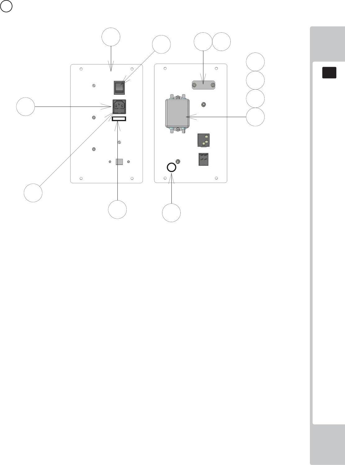
PARTS LIST
18
18
131
5 ASSY AC UNIT (SND-1080UK) (D-1/1)
ITEM PART NUMBER DESCRIPTION QTY
***1 DV-1081UK PLATE AC 1
***2 ST-0403UK PLATE AC CAP 1
***3 LB1096 STICKER PROTECTIVE EARTH 1
***101 EP1302 EUROSOCKET FUSED 10A 250VAC 1
***102 514-5078-3150 FUSE 3.15 T 20MM C RS537-1509 2
***103 SW1109 SWITCH ROCKER 250V AC 1
***104 EP1419 FILTER SCHAFFNER 2030-16-06 1
***108 310-5029-D508 HEAT SHRINK SLEEVING 50.8DIA 4
***109 LB1126-3150-250 FUSE LABEL 3.15A 250V 1
2
***201 029-B00412 M4X12 SKT BH PAS 2
***202 050-F00400 M4 NUT FLG SER PAS 4
***203 060-F00400 M4 WSHR FORM A FLT PAS 2
***204 060-S00400 M4 WSHR SPR PAS 2
***301 SND-60001UK WH AC IN 1
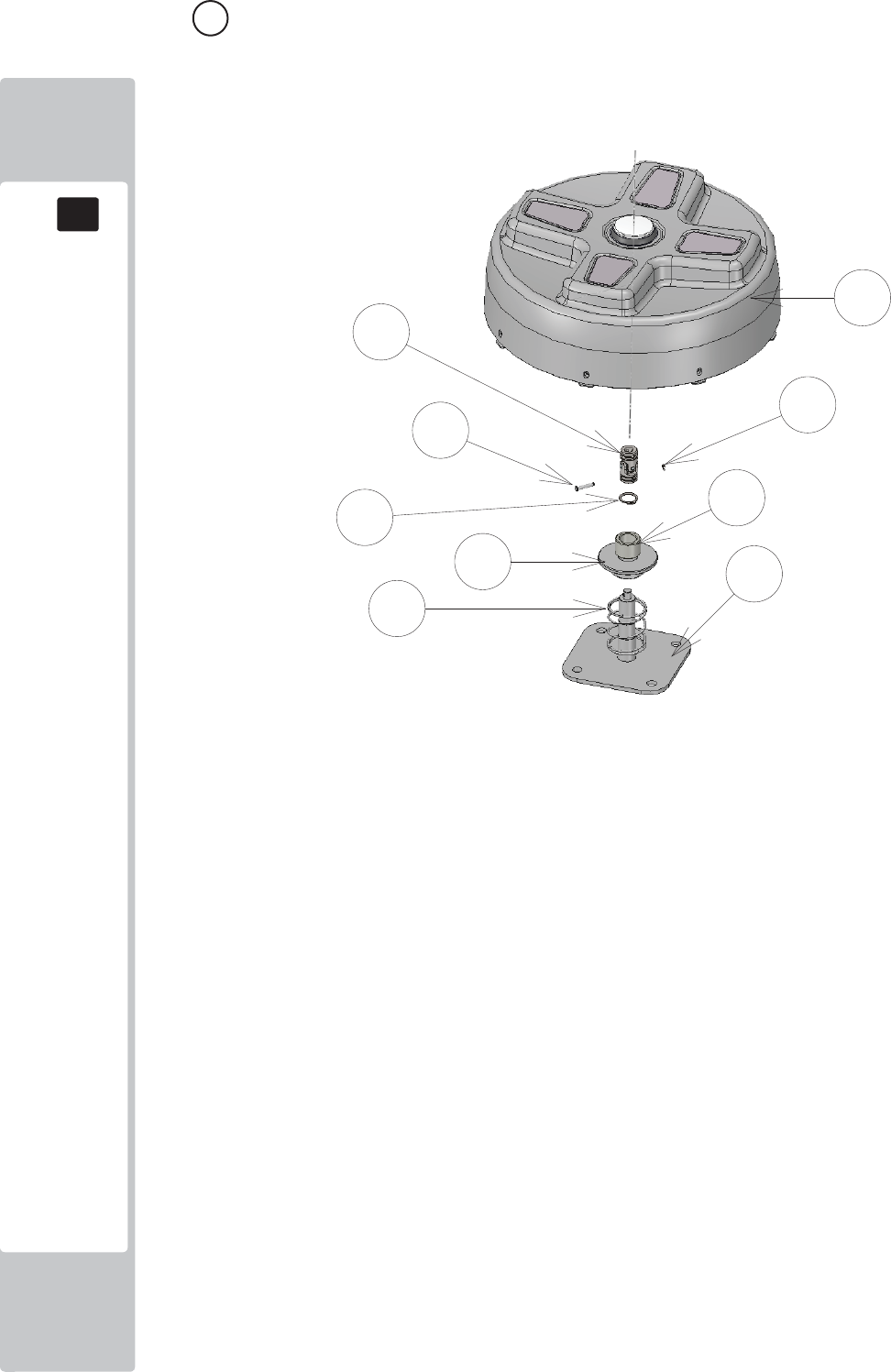
PARTS LIST
18
18
132
6 ASSY DPAD CONTROLLER (SND-1100UK) (D-1/1)
ITEM NO PART NUMBER DESCRIPTION QTY
***1 SND-1101UK BASE CONTROLLER 1
***2 SND-1102UK BASE SPRING RETAINER 1
***3 SND-1103UK BASE SPACER 1
***4 SND-1150XUK SUB ASSY DPAD CONTROLLER 1
***5 SND-1159UK PIN UNIV JOINT RETAIN 1
***101 111-0001-91UK UNIV JOINT 10X20X42 1
***102 125-0004UK SPRING COMP SND DPAD 1
***201 065-C02000 CIRCLIP 20MM 1
***202 065-C04200 CIRCLIP 42MM 1
***203 045-K00438-0Z 4X38 SPIRAL PIN OZ 1
***204 065-E00400 E RING 4MM 1
***301 SND-60014UK WH SERIAL CROSS KEY A 2
***302 SND-60016UK WH SERIAL CROSS KEY B 1
***303 SND-60015UK WH CROSS KEY LED 1
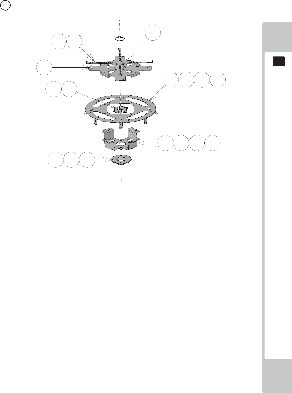
PARTS LIST
18
18
133
7 ASSY SUB ASSY DPAD CONTROLLER (SND-1150UK) (D-1/1)
ITEM NO PART NUMBER DESCRIPTION QTY
****1 SND-1151XUK BASE CONT UPPER 1
****4 SND-1154XUK PLATE DISC 1
****7 SND-1157XUK PLATE CAM 1
****8 SND-1158UK BASE CAM LOWER 1
****101 601-13101-003 CROSS KEY LED ELE-F01770 4
****102 EP1464 SW MICRO RS 159-4411 4
****104 280-L00811-OS STANDOFF 7.94OD 3.56ID 11.11L 8
****201 029-B00412 M4X12 SKT BH PAS 8
****202 060-S00400 M4 WSHR SPR PAS 8
****203 068-441614 M4 WSHR 16OD FLT PAS 8
****204 029-B00612 M6X12 SKT BH PAS 4
****205 060-S00600 M6 WSHR SPR PAS 4
****206 068-652016 M6 WSHR 20OD FLT PAS 8
****207 050-U00600 M6 NUT NYLOK PAS 4
****208 020-B00316-0B M3X16 SKT BH BLK 16
****301 SND-60014UK WH SERIAL CROSS KEY A 2
****302 SND-60015UK WH CROSS KEY LED 1
****303 SND-60016UK WH SERIAL CROSS KEY B 1
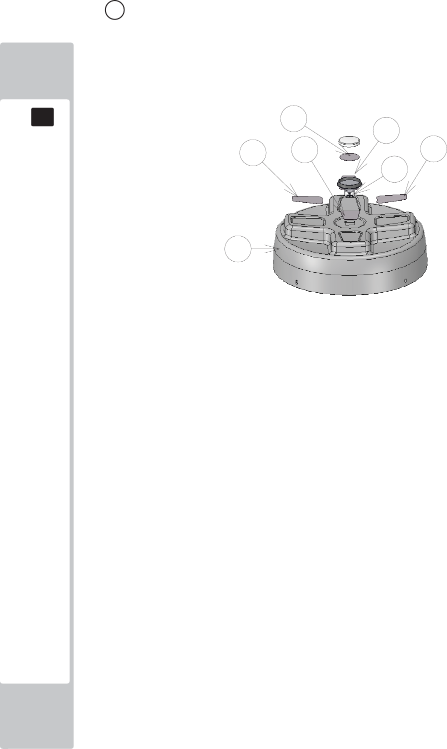
PARTS LIST
18
18
134
8 ASSY DPAD COVER (SND-1170UK) (D-1/1)
ITEM NO PART NUMBER DESCRIPTION QTY
***1 SND-1160UK COVER DPAD 1
***2 SND-1161-01UK DECAL DPAD L 1
***3 SND-1161-02UK DECAL DPAD R 1
***4 SND-1161-03UK DECAL DPAD UP 1
***5 SND-1161-04UK DECAL DPAD DOWN 1
***6 SND-1305UK BUTTON INFILL/INSERT 1
***101 509-0011-01 GPB890 LR HALO BLK/BLU LED U2 1
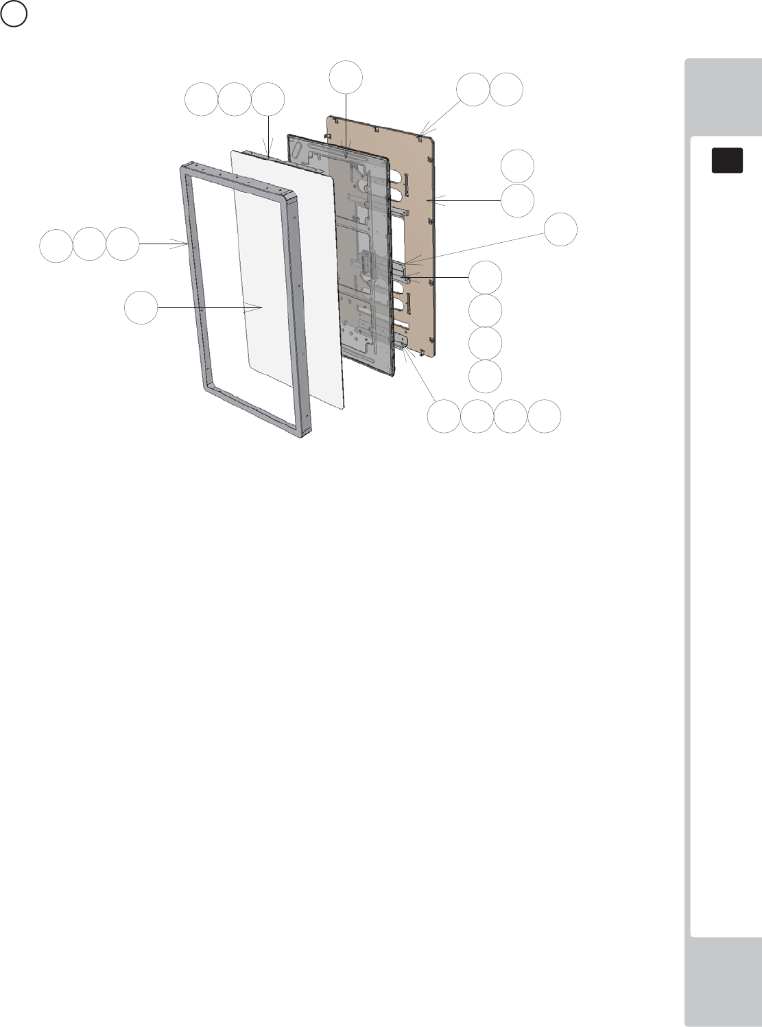
PARTS LIST
18
18
135
9 ASSY MONITOR 55" (SND-1250UK) (D-1/1)
ITEM NO PART NUMBER DESCRIPTION QTY
***1 RND-0198 SND MASK MON 55 METAL 1
***2 SND-1202UK BRKT MONITOR MTG 2
***3 SND-1253UK BRKT GLASS RETAIN HORIZ 55 2
***4 SND-1204UK BRKT MON MASK SUPP 13
***5 SND-1255UK GLASS MONITOR 55 1
***6 SND-1256UK PANEL MONITOR BACK 55 1
***7 SND-1257UK SPACER MTG 55 2
***8 SND-1009UK BRKT SUPP LWR MON 42 1
***101 200-6055-03-AUO 55" LED AUO P550HVN02.2 1
***102 OS1230 FOAM STRIP 2MM X 10MM 1.1
***201 029-B00412-0B M4X12 SKT BH BLK 21
***202 068-441614-0B M4 WSHR 16OD FLT BLK 21
***203 029-B00812-0B M8X12 SKT BH BLK 4
***204 060-S00800-0B M8 WSHR SPR BLK 4
***205 068-852216-0B M8 WSHR 22OD FLT BLK 4
***206 029-B00616-0B M6X16 SKT BH BLK 3
***207 060-S00600-0B M6 WSHR SPR BLK 3
***208 068-652016-0B M6 WSHR 20OD FLT BLK 3
***209 012-P03512-FB N6x1/2" S/TAP FLG BLK 13
***210 012-F03532 N6X1 1/4" S/TAP CSK PAS 4
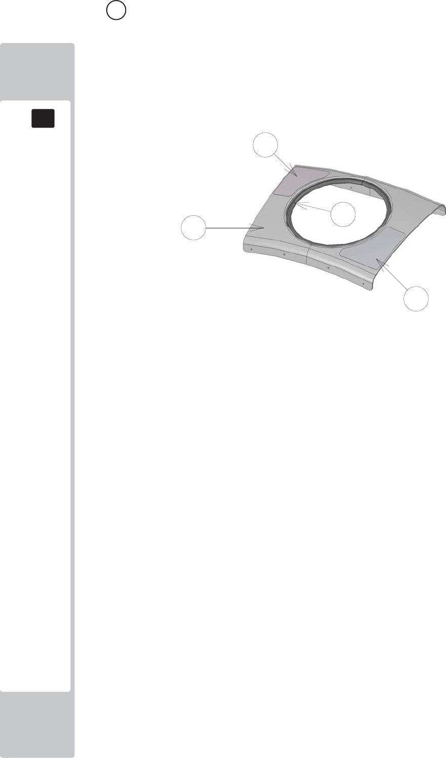
PARTS LIST
18
18
136
10 ASSY CTRL PAN (SND-1300UK) (D-1/1)
ITEM NO PART NUMBER DESCRIPTION QTY
***1 SND-1301UK COVER CTRL PNL 1
***3 SND-1303UK STICKER START SURROUND 1
***4 SND-1304UK STICKER PLAY INST 1
***102 OS1253 EDGING RUBBER BODY SIDE SEAL 1.2
****108 310-5029-D508 HEAT SHRINK SLEEVING 50.8DIA 4
****109 LB1126-5-250 FUSE LABEL 5A 250V 1
****201 000-P00308-W M3X8 MSCR PAN W/FS PAS 2
****202 050-F00400 M4 NUT FLG SER PAS 4
****301 TFF-60001UK WH AC IN 1
****302 600-9020-44K WH EARTH 200MM M4/M4 1
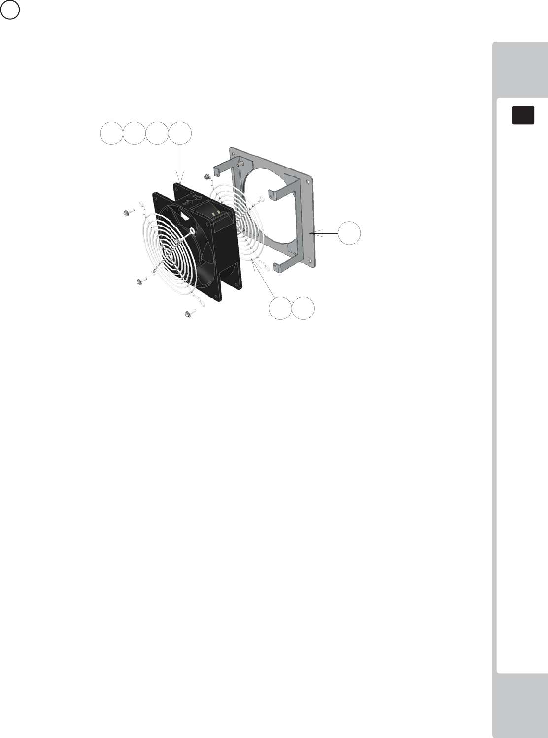
PARTS LIST
18
18
137
ITEM NO PART NUMBER DESCRIPTION QTY
***1 SND-1341UK BRKT FAN MTG 1
***101 260-0012-01UK FAN DC 12V AXIAL 1
***102 FN1012 FAN GUARD METAL 120MM (FG-12) 2
***201 020-B00316-0B M3X16 SKT BH BLK 4
***202 060-S00300-0B M3 WSHR SPR BLK 4
***203 060-F00300-0B M3 WSHR FORM A FLT BLK 4
***204 050-U00400 M4 NUT NYLOK PAS 4
****202 050-F00400 M4 NUT FLG SER PAS 4
****301 TFF-60001UK WH AC IN 1
****302 600-9020-44K WH EARTH 200MM M4/M4 1
11 ASSY FAN (SND-1340UK) (D-1/1)
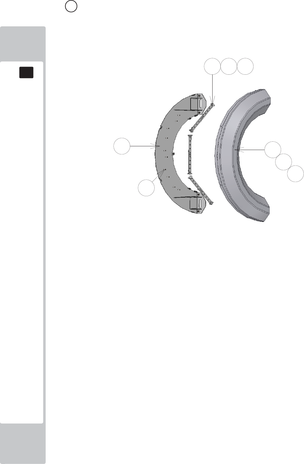
PARTS LIST
18
18
138
12 ASSY HALF HOOP L (SND-1400UK) (D-1/1)
ITEM NO PART NUMBER DESCRIPTION QTY
***1 SND-1401XUK BRKT BASE HALF LOOP 1
***2 SND-1402-02UK COVER SIDE RING (HALF) 1
***101 601-13101-001 HALF RING LED ELE-F01750 3
***102 280-L00605-OS STANDOFF 6.35OD 3.56ID 4.76L 10
***201 029-B00412 M4X12 SKT BH PAS 7
***202 068-441614 M4 WSHR 16OD FLT PAS 7
***203 020-B00316-0B M3X16 SKT BH BLK 10
***204 068-330808-PN M3 WSHR 8OD FLT NYLON 10
***301 SND-60013UK WH SERIAL RGB XY 2
***302 SND-60021UK WH LED HALF HOOP L 1
***303 SND-60022UK WH LED HALF HOOP EXTENSION A 1
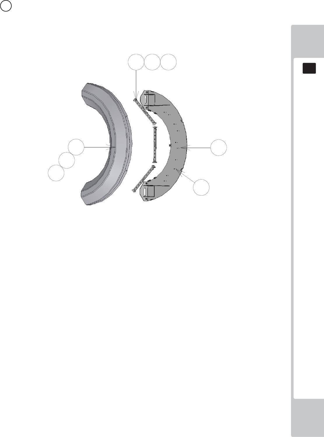
PARTS LIST
18
18
139
13 ASSY HALF HOOP R (SND-1450UK) (D-1/1)
ITEM NO PART NUMBER DESCRIPTION QTY
***1 SND-1401XUK BRKT BASE HALF LOOP 1
***2 SND-1402-02UK COVER SIDE RING (HALF) 1
***101 601-13101-001 HALF RING LED ELE-F01750 3
***102 280-L00605-OS STANDOFF 6.35OD 3.56ID 4.76L 10
***201 029-B00412 M4X12 SKT BH PAS 7
***202 068-441614 M4 WSHR 16OD FLT PAS 7
***203 020-B00316-0B M3X16 SKT BH BLK 10
***204 068-330808-PN M3 WSHR 8OD FLT NYLON 10
***301 SND-60013UK WH SERIAL RGB XY 2
***302 SND-60030UK WH LED HALF HOOP R 1
***303 SND-60022UK WH LED HALF HOOP EXTENSION A 1
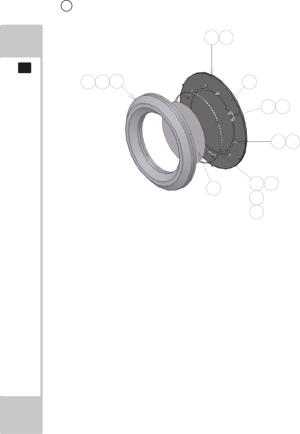
PARTS LIST
18
18
140
14 ASSY FULL HOOP L (SND-1500UK) (D-1/2)
ITEM NO PART NUMBER DESCRIPTION QTY
***1 SND-1501XUK DISC L 1
***2 SND-1402-01UK COVER SIDE RING 1
***3 SND-1512XUK BRKT LED MTG FULL HOOP 10
***5 SND-1505UK INFILL FULL HOOP L 1
***6 SND-1510XUK BRKT LED MTG FULL HOOP DUAL 3
***7 SND-1511XUK BRKT LED MTG FULL HOOP 6
***101 601-13101-002 RING LED ELE-F01760 3
***102 280-L00605-OS STANDOFF 6.35OD 3.56ID 4.76L 12
***201 029-B00412 M4X12 SKT BH PAS 9
***202 068-441614 M4 WSHR 16OD FLT PAS 9
***203 012-P03512-FB N6x1/2" S/TAP FLG BLK 28
***204 020-B00316-0B M3X16 SKT BH BLK 12
***205 068-330808-PN M3 WSHR 8OD FLT NYLON 12
***301 SND-60013UK WH SERIAL RGB XY 2
***302 SND-60024UK WH LED FULL HOOP L 1
*****304 600-9020-44K WH EARTH 20CM M4M4 1
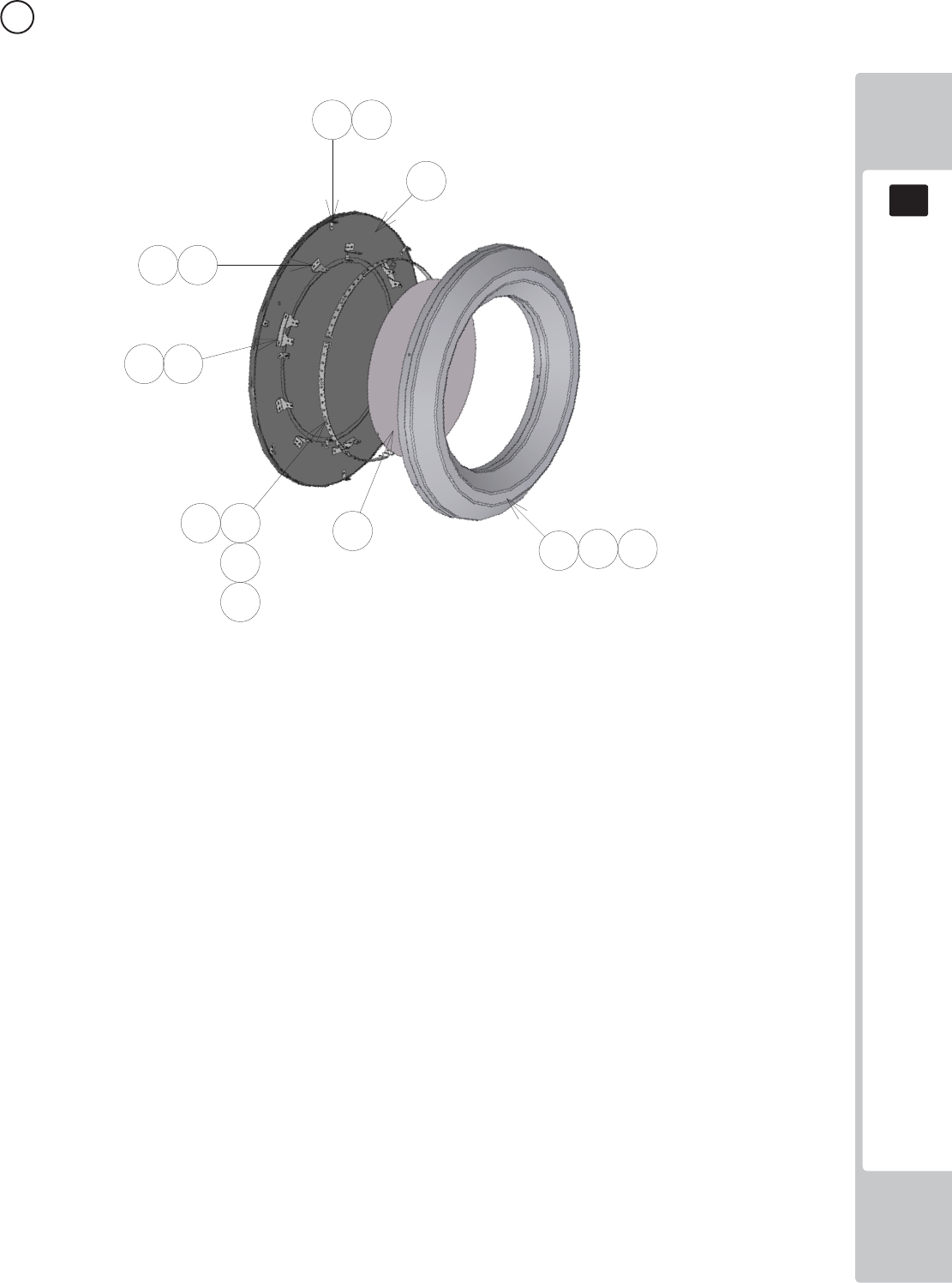
PARTS LIST
18
18
141
15 ASSY FULL HOOP L (SND-1550UK) (D-1/2)
ITEM NO PART NUMBER DESCRIPTION QTY
***1 SND-1551XUK DISC R 1
***2 SND-1402-01UK COVER SIDE RING 1
***3 SND-1512XUK BRKT LED MTG FULL HOOP 10
***5 SND-1506UK INFILL FULL HOOP R 1
***6 SND-1510XUK BRKT LED MTG FULL HOOP DUAL 3
***7 SND-1511XUK BRKT LED MTG FULL HOOP 6
***101 601-13101-002 RING LED ELE-F01760 3
***102 280-L00605-OS STANDOFF 6.35OD 3.56ID 4.76L 12
***201 029-B00412 M4X12 SKT BH PAS 9
***202 068-441614 M4 WSHR 16OD FLT PAS 9
***203 012-P03512-FB N6x1/2" S/TAP FLG BLK 28
***204 020-B00316-0B M3X16 SKT BH BLK 12
***205 068-330808-PN M3 WSHR 8OD FLT NYLON 12
***301 SND-60013UK WH SERIAL RGB XY 2
***302 SND-60025UK WH LED FULL HOOP R 1

PARTS LIST
18
18
142
16 ASSY MAIN ELEC (SND-4000UK) (D-1/2)
ITEM NO PART NUMBER DESCRIPTION QTY
***1 SND-4001UK WOODEN BASE MAIN 1
***2 SND-4002UK PLATE PSU MTG 1
***101 837-14572 I/O CONTROL BD 3 FOR JVS COM 1
***102 400-100-012-02 PSU 12VDC 100W MW SP-100-12 1
***103 400-100-05-01 PSU 5V 100W MW LPS-100-05 1
***104 400-150-012-02 PSU 12VDC 150W MW SP-150-12 1
***105 601-13101-004 LED CONTROL BD ELE-F01780 1
***106 838-14551-02UK AC DISTRIBUTION BD 1
***107 838-8001UK AMP 2.2 VISATON 1
***108 CFB-4003-01UK EARTH PLATE 1
***109 280-A01264-WX ROUTER TWIST D12 SO6.4 WOOD X 8
***110 280-A02064-WX ROUTER TWIST D20 SO6.4 WOOD X 8
***111 OS1011 PCB FEET 8
***201 029-B00412 M4X12 SKT BH PAS 12
***202 060-S00400 M4 WSHR SPR PAS 12
***203 068-441614 M4 WSHR 16OD FLT PAS 4
***204 012-P00325 N4X1" S/TAP PAN PAS 8
***205 012-P00312 N4X1/2" S/TAP PAN PAS 8
***206 012-P03512-FB N6x1/2" S/TAP FLG BLK 4
***301 SND-60002UK WH AC DISTRIBUTION 1
***302 SND-60003UK WH DC DISTRIBUTION 1
***303 SND-60004UK WH MONITOR PSU 1
***304 SND-60005UK WH I/O 1
***305 SND-60017UK WH SPEAKERS A 1
***305 SND-60026UK WH LED CNTRL B1 1
***306 SND-60028UK WH LED CNTRL A1 1
***306 EP1467 USB A - USB MINI 2M 1
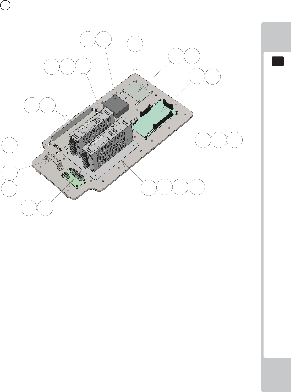
PARTS LIST
18
18
143
16 ASSY MAIN ELEC (SND-4000UK) (D-2/2)
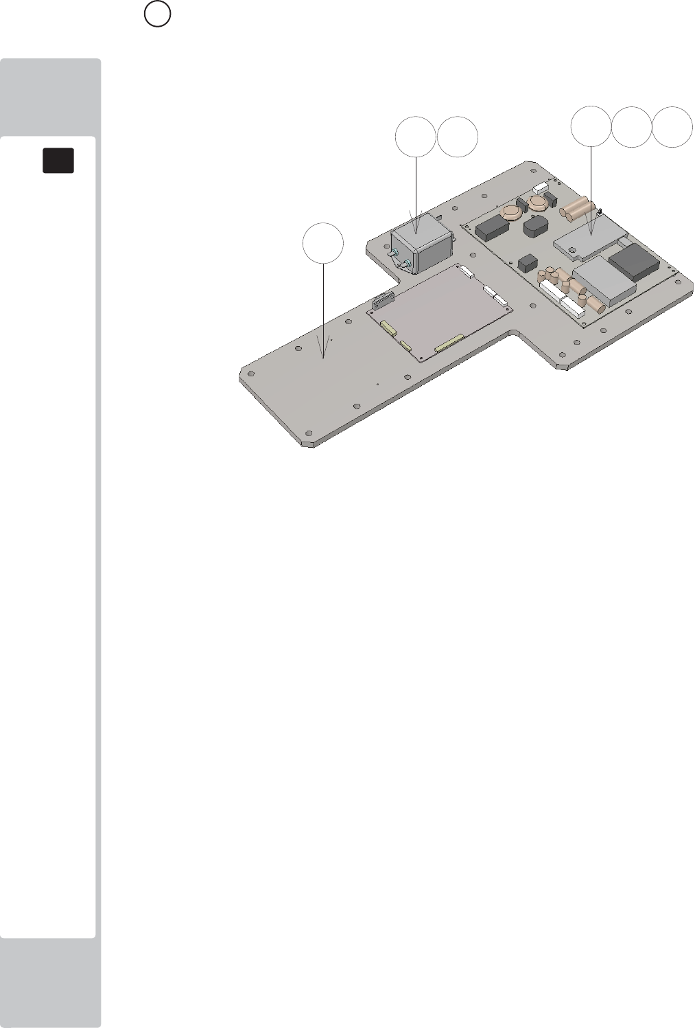
PARTS LIST
18
18
144
17 ASSY LED MONITOR ELEC (SND-4100UK) (D-1/1)
ITEM NO PART NUMBER DESCRIPTION QTY
***1 SND-4101UK PLATE PRISMA BD DMODUL MOUNT 1
***2 440-DS0010UK LABEL DANGER HI VOLT GEN 1
***101 400-160-51224 PSU 42" LED DPS-160AP-2A-PD02 1
***102 280-A01264-WX ROUTER TWIST D12 SO6.4 WOOD X 12
***103 280-L00709-OS STANDOFF 70D 4ID 9L 10
***104 EP1419 FILTER SCHAFFNER 2030-16-06 1
***201 012-P00325 N4X1" S/TAP PAN PAS 10
***202 012-P03512-FB N6x1/2" S/TAP FLG BLK 2
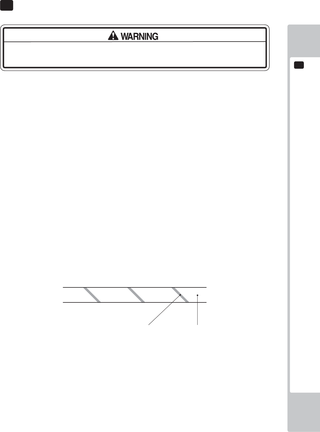
WIRE COLOUR CODE TABLE
19
145
The color codes for the wires used in the diagrams in the following chapter are as follows.
A PINK
B SKY BLUE
C BROWN
D PURPLE
E LIGHT GREEN
Wires other than those of any of the above 5 single colors will be displayed by 2 alphanumeric
characters.
1 RED
2 BLUE
3 YELLOW
4 GREEN
5 WHITE
7 ORANGE
8 BLACK
9 GRAY
If the right-hand side numeral of the code is 0, then the wire will be of a single color shown by the left-
hand side numeral (see the above).
Note 1: If the right-hand side numeral is not 0, that particular wire has a spiral color code. The left-
hand side character shows the base color and the right-hand side one, the spiral color.
<Example> 51………WHITE/RED
RED WHITE
Note 2: The character following the wire color code indicates the size of the wire.
U : AWG16
K : AWG18
L : AWG20
None : AWG22
The DC power wire color for this product is diff erent from previous SEGA titles. Working
from the previous wire colors will create a high risk of fi re.
19 COLOUR CODE TABLE
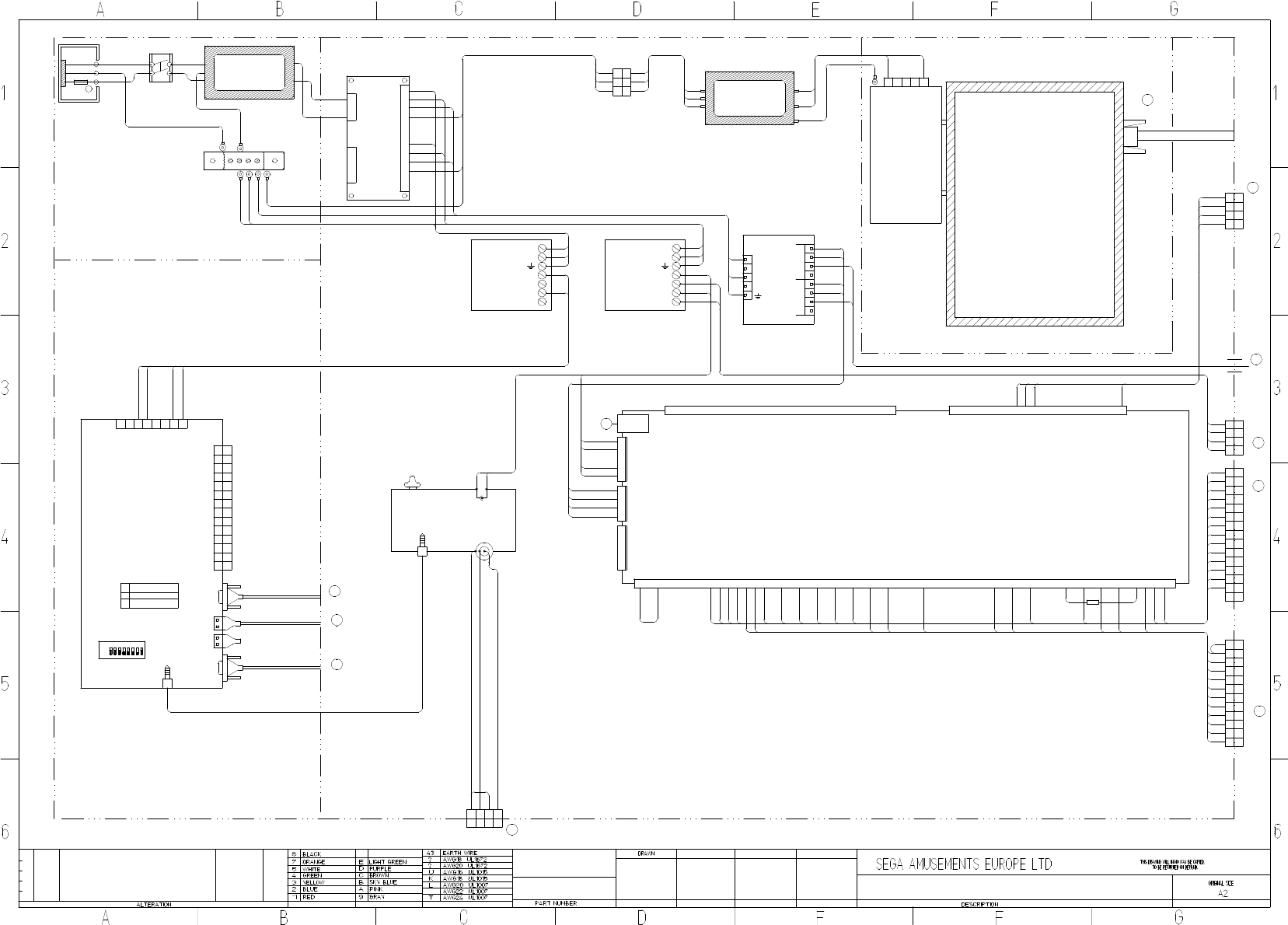
CFB-4003-01UK
EARTH PLATE
838-14551-02UK
AC DISTRIBUTION BOARD
VLR-04V VLR-03V
VLR-12V
1
2
3
1
2
3
4
1
2
3
4
5
6
7
8
9
10
11
12
(L)
(N)
43K
20K
C0K
5
4
3
2
1
55" LED AUO
200-6055-02-AUO
C0L
20L
C0L
20L
C0L
20L
20L
C0L
+5V
+5V
GND
GND
USB A
NH-4P
+EXV
+EXV
+5V
+5V
+5V
+5V
+5V
+5V
GND
GND
GND
GND
GND
GND
GND
GND
+12V
+12V
+12V
+12V
+12V
+12V
+5V
AVCC
AGND
AVCC
AGND
1 2 3 4 5 6 7 8 9 10 11 12 13 14 15 16 17 18 19 20 21 22 23 24 25 26
1610 2317 211813 1514 19 20 261211 25243 2254 71 2 6 98
1610 17 1813 1514 19 2012113 54 71 2 6 98
27 28 29 30 31 32 33 34 35 36 37 38 39 40 41 42 43 44 45 46 47 48 49 50 51 52 53 54 55 56 57 58 59 60
837-14572
I/O CONTROL BOARD 3
FOR JVS COM
1
2
3
4
1
2
3
4
5
+12V
+12V
GND
GND
NH-5P
+12V
+12V
GND
GND
5
1
2
3
4
NH-5P
START1
START2
KEY- RIGHT
KEY LEFT
KEY -UP
KEY - DOWN
TICKET RELEASE
TICKET EMPTY
TICKET COUNT (NOTCH)
SERVICE
TEST
COIN IN
COIN2 RESERVED
COIN METER
START LAMP
TICKET PAY (DRIVE)
TICKET METER
+5V
GND
GND
BOTTOM LED (R)
BOTTOM LED (G)
BOTTOM LED (B)
KEY LED (R)
KEY LED (G)
KEY LED (B)
CONTROL LED (R)
CONTROL LED (G)
CONTROL LED (B)
30X2 & 30
80
30
30
80
1
2
3
4
3
4
2
1
YL
P C
30
30
80
80
3.5mm AUDIO JACK
LINE IN
12V
+
-
AUDIO OUT
3.5mm AUDIO JACK
VOLUME CONTROL
838-8001UK
AMP 2.2 VISATON
30
80
1
2
3
4
91
98
92
98X2
C0L
20L
10
10
80
80
80
10
30
30
80
80
VL
1
2
3 3
2
1
P C
C0L
43K
20L 20L
43K
C0L
1
2
3
4
5
6
7
8
9
10
11
12
13
14
7
11
6
4
3
10
14
9
1
12
2
13
5
8
P C
YL
BUTTONS & CREDIT
80
80
80
80
15
21
27
23
24
32
25
30
30
30
30
30
21
27
23
24
25
15
80
80
80
80
80
80
2
9
7
6
7
4 4
P C
3
9
1
2
5
8 8
6
3
5
1
30
75
D5
48
30X2
30
48
D5
75
45
51
51
45
80
80X2
YL
TEST & SERVICE & TICKET MECH
2
4 4
P C
3
1
2
3
1
YL
A1
A4
A2
30
A2
A1
A4
30
LEDS
FAN & BB LED
P550HVN02.0
PSU 55" LED DPS-283APA-ESS5
400-283-51224
EP1419
NOISE FILTER
2030-16-06
(N)
(L)
(N)
(L)
(E)
20K
C0K
20L
C0L
43K
43K
M4
80
32
80
15 15
4
3
2
1
YL
P C
M4
M4
SND-60001UK
SW1103
SWITCH
EP1302
IEC INLET
5A T
514-5078-5000
(N)
(E)
(L)
EP1419
NOISE FILTER
2030-16-06
(N)
(L)
(N)
(L)
(E)
C0L
20L
43K
400-100-012-02
SP-100-12
7- V+
6- V+
5- V-
4- V-
3-
2-AC/N
1-AC/L
20L
C0L
43K
30X2
80X2 & 80
80X2
400-150-012-02
SP-150-12
7- V+
6- V+
5- V-
4- V-
3-
2-AC/N
1-AC/L
20L
C0L
43K
80X2
30X2
SND-60002UK_R3
SND-60003UK_R3
SND-60003UK_R3
SND-60004UK
SND-60005UK_R3
SND-60005UK_R3
SND-60017UK
SND-4000UK ASSY MAIN ELEC
SND-4000UK ASSY MAIN ELEC
SND-1000UK - ASSY MAIN CABI 42" LED
DV-1080UK -ASSY AC UNIT
SND-1250UK - ASSY MONITOR 55"
M4
20L
C0L
C0L
20L
C0L
20L
43K
C0L
20L
C0L
20L
43K
30
A
G
C
A1 2/2
G4 2/2
E4 2/2
A3 2/2
D
A4 2/2
E
F
A6 2/2
SPEAKERS
D3 2/2
H
D3 1/2
I
G1 1/2
J
B5 1/2
I
B5 1/2
J
SND-60003UK_R3 SND-60003UK_R3
7
LV-
VH
PSU 100W 5V
8
1
VH
LPS-100-5
4
400-100-05-01
1
V+
3
2
N
56
3
2
5
4
10
10
80
80
10
10
D1
12
11
10
11
12
10
D1
80
600-7500-180UK
600-7141-100UK
VGA
600-7155-0180UK
600-7141-100UK
600-7009-2500UK
0.25" TAG AND BOOT0.25" TAG AND BOOT
600-7009-2500UK
ON
7
8
VH
YL
ASSY NUSX GAMEBOARD
7
USB B
DVI
1
2
3
4
5
6
1
2
3
4
5
6
7
8
9
10
11
12
13
C P
3
2
1
14
3.5mm AUDIO JACK
USB A
COM1
DRIVE BD
848-1001D
DIP SWITCH
2 RXD (BROWN)
3 TXD (BLUE)
5 GND (SHIELD)
8
4 5
14
13
VIDEO OUT
9
7
12
6
4
3
D-SUB9P
5
1
11
10
OFF
8
6
2
D7
D7
PAGE 1 OF 2
SONIC DASH EXTREME
SND-0000UK
30/4/2015
SD
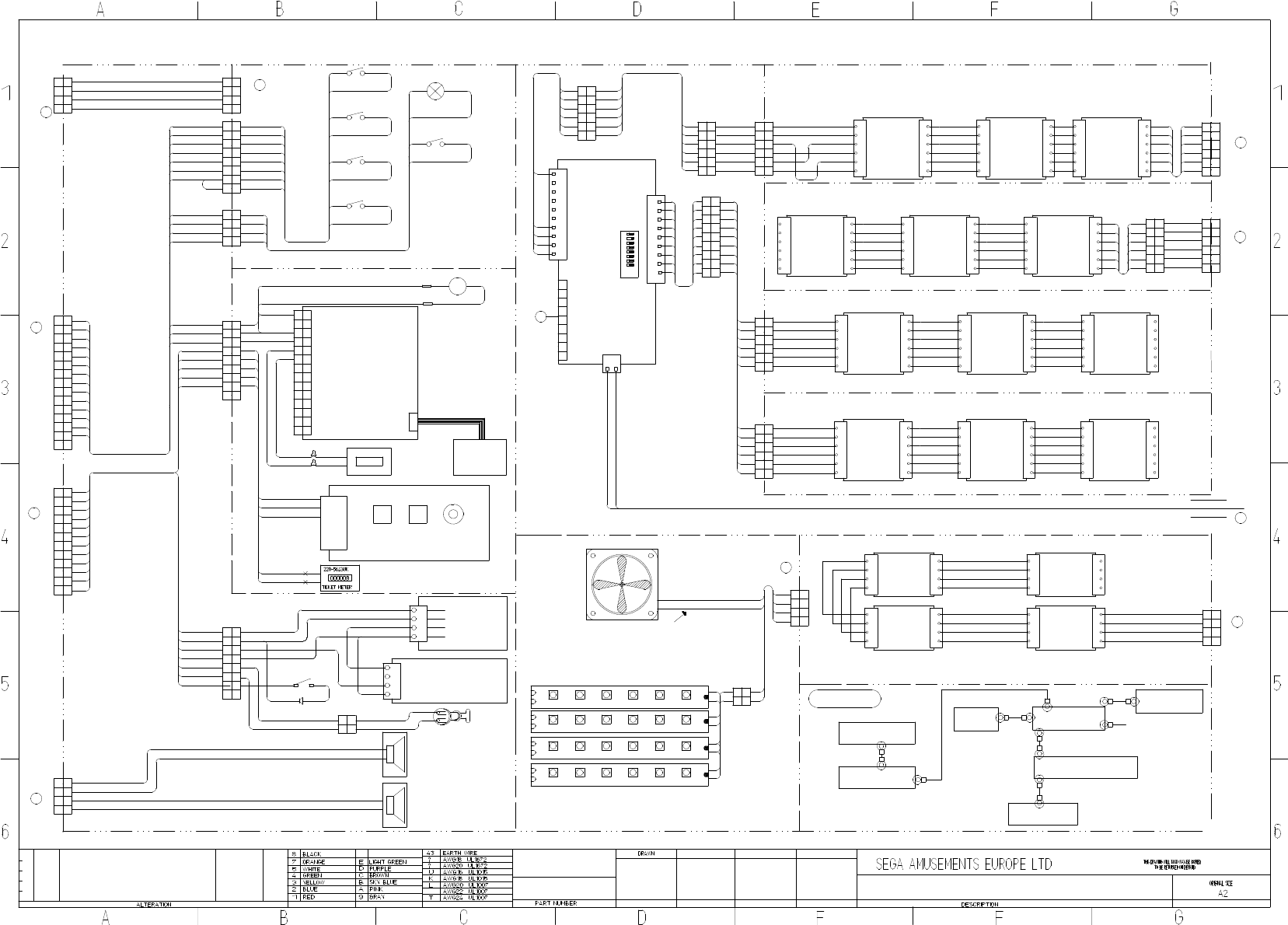
130-010-04020
130-010-04020
91
98
91
98
1
4
3
98
2
92
91
98
2
9
14
7
11
6
7
12
10
4 4
P C
3
10
13
14
9
1
11
12
2
13
5
8 8
25
6
3
5
YL
BUTTONS & CREDIT
1
80
30
80
32
80
80
27
21
24
30
15
23
TEST & SERVICE & TICKET MECH
YL
80
80
45
51
75
D5
48
30
30
1
5
3
6
88
5
2
1
9
3
P C
44
7
6
7
9
2
80
80
30
30 C P
YL
1
2
4
3
4
3
2
1
2
3
4
1
P C
YL
1
2
3
4
3
4
2
1
YL
P C
START LAMP
START
25
30
15
80
30
25
15
80
80
25
15
30
80
24
DOWN
23
UP
80
27
RIGHT
80
21
LEFT
80
2
1
P C
3
4 4
3
1
2
24
23
27
21
6
5
7
YL
8 8
7
5
6
80
80X2
80
80 80
80
80
80
21
27
23
24
2
1
P C
3
YL
3
1
2
32
80
30
80X2
32
30X2 COIN INSERT LAMP
80
30
0.11"
0.11"
L
32
30
80
1
2
3
4
5
6
7
8
9
10
11
12
13
14
00000
EP1380-01
C
11
10
14
12
8
9
13
7
6
5
1
2
4
3
P
+12V
KEY
0V
COIN SIGNAL
+12V
METER OUT
EXCEL CREDIT BOARD
220-5643UK
COIN METER
220-5610-01
SR3 COIN MECH
10W RIBBON CABLE
10
80
30
89
30
80
1
2
3
4
5
6
838-14548-01AUK
SWITCH & VOLUME CONTROL BOARD
TEST SERVICE VOLUME
TEST
SERVICE
GND
VOL 1
VOL 2
VOL 3
30
45
35
35
51
80
30x2
1
2
3
4
NOTCH
GND
ENABLE
12V
MOLEX 03-09-1042
220-0001-01UK
TICKET VEND
UNIT TD-963CR
1
3
2
430
45
80X2
51
1
3
2
4
YL
P C
30
80
51
45
80
75
D5
81
30
CRIMPS
SPEAKERS
30
80
+
-
44
30 P C
3
1
YL
3
2
1
2
A1
A4
A2
AVATAR RGB LED
1
XH
R
B
XH
1+
3
3
4
2
4
2
LED505.PCBX2
G
+
B
G
R
A4
30
A2
A1
AVATAR RGB LED
1
XH
R
B
XH
1+
3
3
4
2
4
2
LED505.PCBX2
G
+
B
G
R
A2
A4
A1
30
A2
A4
A1
30
A4
A2
A4
AVATAR RGB LED
1
XH
R
B
XH
1+
3
3
4
2
4
2
LED505.PCBX2
G
+
B
G
RA1A1
A2
3030
AVATAR RGB LED
1
XH
R
B
XH
1+
3
3
4
2
4
2
LED505.PCBX2
G
+
B
G
R
A2
A4
A1
30
A2
A4
A1
30
CROSS KEY LED
80
CLK
4
SDI
11
3
XH
TCK
2
4
2
GND
3
XY-LED1.1
XH
5
6 6
5
+5V
+5V
+5V
GND
TCK
CLK
+5V
SDI
IN OUT
CLK
4
SDI
11
3
XH
TCK
2
4
2
GND
3
XY-LED1.1
XH
5
6 6
5
+5V
+5V
+5V
GND
TCK
CLK
+5V
SDI
IN OUT
CLK
4
SDI
11
3
XH
TCK
2
4
2
GND
3
XY-LED1.1
XH
5
6 6
5
+5V
+5V
+5V
GND
TCK
CLK
+5V
SDI
IN OUT
1
2
3
4
5
6
7
8
9
10
2
3
1
4
5
6
7
8
1
2
9
8
7
6
5
4
3
2
1
9 PIN D TYPE
VH
XY-IC1.1
LED CONTROLLER
+5V
GND
9
65432
OFF DIP SWITCH
ON
1 87
1-770602-0
10 WAY
AMP CST
AMP CST
770602-9
9 WAY
10
80
10
72
74
71
80
P C
YL
50
50
50
50
50
50
50
50
50
50
50
50
50
50
50
50
50
50
50
50
50
50
50
50 CLK
4
SDI
11
3
XH
TCK
2
4
2
GND
3
XY-LED1.1
XH
5
6 6
5
+5V
+5V
+5V
GND
TCK
CLK
+5V
SDI
IN OUT
CLK
4
SDI
11
3
XH
TCK
2
4
2
GND
3
XY-LED1.1
XH
5
6 6
5
+5V
+5V
+5V
GND
TCK
CLK
+5V
SDI
IN OUT
CLK
4
SDI
11
3
XH
TCK
2
4
2
GND
3
XY-LED1.1
XH
5
6 6
5
+5V
+5V
+5V
GND
TCK
CLK
+5V
SDI
IN OUT
80
71
10
74
72
10
6
3
5
2
YL
C P
3
2
5
4
1
4
6
180
74
72
10
71
10
50
50
50
50
50
50
50
50
50
50
50
50
50
50
50
50
50
50
71
74
72
91
94
92
50
50
50
50
50
50
50
50
50
50
50
50
50
50
50
50
50
50
CLK
4
SDI
11
3
XH
TCK
2
4
2
GND
3
XY-LED1.1
XH
5
6 6
5
+5V
+5V
+5V
GND
TCK
CLK
+5V
SDI
IN OUT
50
50
50
50
50
50
CLK
4
SDI
11
3
XH
TCK
2
4
2
GND
3
XY-LED1.1
XH
5
6 6
5
+5V
+5V
+5V
GND
TCK
CLK
+5V
SDI
IN OUT
CLK
4
SDI
11
3
XH
TCK
2
4
2
GND
3
XY-LED1.1
XH
5
6 6
5
+5V
+5V
+5V
GND
TCK
CLK
+5V
SDI
IN OUT
CLK
4
SDI
11
3
XH
TCK
2
4
2
GND
3
XY-LED1.1
XH
5
6 6
5
+5V
+5V
+5V
GND
TCK
CLK
+5V
SDI
IN OUT
CLK
4
SDI
11
3
XH
TCK
2
4
2
GND
3
XY-LED1.1
XH
5
6 6
5
+5V
+5V
+5V
GND
TCK
CLK
+5V
SDI
IN OUT
CLK
4
SDI
11
3
XH
TCK
2
4
2
GND
3
XY-LED1.1
XH
5
6 6
5
+5V
+5V
+5V
GND
TCK
CLK
+5V
SDI
IN OUT
50
50
50
50
50
50
50
50
50
50
50
50
50
50
50
50
50
50
50
50
50
50
50
50
15 15
SND-1400UK - ASSY HALF HOOP L
SND-1550UK - ASSY FULL HOOP R
10
80
72
10
74
71
P C
P C
80
91
80
10
92
10
94
-
+
390-2112- WUK LED STRIP RIGID WHITE
80
30
YL
P C
1
22
1
x
x
80
30
BOMB
30X2
80X2
EARTH MAP
YL
P C
2
9
7
6
7
4 4
P C
3
9
1
2
5
8 8
6
3
5
1
YL
80X2
10X2
10X2
92
94
91
72
74
71
TICKET LEVEL SWITCH
& LED
80
EP1820
EP1421
M4
M5
M4
M4
M4
M4
M4M4
M4 SND-60004UK
FILTER
SND-60002UK
TEST & SERV BRKT
PSU PLATE
EATH PLATE
AC BRKT
M4
M4
COIN DOOR
SND-1000UK - ASSY MAIN CABI 42" LED
SND-60007UK_R3
SND-60007UK_R3
SND-60018UK_R1
SND-60009UK_R3
SND-60006UK_R2
SND-60012UK_R3
SND-1100UK - ASSY DPAD CONTROLLER
RD-0320UK - ASSY SWITCH UNIT
SND-1000UK - ASSY MAIN CABI 42" LED
6
3
5
2
P C
5
YL
1
2
3
6
1
44
1
4
3
6
3
5
2
4
5
C P
6
1
2
YL
SND-1450UK - ASSY HALF HOOP R
SND-60028UK_R1
SND-60020UK
SND-60026UK_R1
SND-60027UK SND-60021UK_R2 SND-60013UK_R1
SND-60025UK_R1
SND-60024UK_R1
SND-1500UK - ASSY FULL HOOP L
SND-60022UK_R1
SND-60029UK_R1
SND-4000UK ASSY MAIN ELEC
SND-1340UK - ASSY FAN
SND-60015UK
SND-60014UK
SND-60014UK
SND-60016UK
SND-60008UK_R2
SND-1100UK - ASSY DPAD CONTROLLER
SND-60003UK_R2
024
SND-6001UK_R2
EP1464
EP1464
EP1464
EP1464
G4 1/2
D
E
G5 1/2
F
C6 1/2
G2 2/2
B
G1 2/2
B
SND-60030UK_R1
G3 1/2
G
B4 1/2
H
SD SONIC DASH EXTREME
G3 1/2
C
G2 1/2
A
SND-60007UK_R3
A1
30
A4
A2
30
2
1
A4
2
3
YL
1
3
P C
4 4
A1
A2 2
4 4
C P
3
1
2
3
1
YL
LEDS
K
B1 2/2
G5 2/2
K
260-0012-01UK
600-9025-44K
600-9050-45K
600-9050-44K
600-9150-44K
10
12
11
10
11
12
80
D1
6
5
6
5
D1
80
1
2
3
4
838-0015UK
TICKET INTERFACE BD
NH 4P
+12V
DRV IN
DRV OUT
D1
80
ASSY TICKET RELEASE BTN
2
P C
1
2
1
JST SM2 WAY
80
D1
80
D1 80
D1
MOMENTARY PUSH BUTTON SWITCH
RS Stock No.133-6502
Mfr. Part No.MSP121CSW
10
10
71
74
72
91
94
92
10
10
80
1
5
3
6
5
2
1
3
44
6
2
1
5
3
6
5
2
1
3
44
6
2
94
10
92
10
80
91
71
74
10
72
80
10
1
5
3
6
5
2
1
3
44
6
2
1
5
3
6
5
2
1
3
44
6
2
10
10
71
74
72
80 80
10
74
71
72
10
71
10
74
10
80
72
10
10
71
74
72
80
SND-60013UK_R1
SND-60013UK_R1 SND-60013UK_R1
SND-60013UK_R1 SND-60013UK_R1
SND-60013UK_R1 SND-60013UK_R1
SND-6002UK
10
10
71
74
72
80
10
10
71
74
80
72 10
72
74
10
71
80
024
-
+
390-2112- WUK LED STRIP RIGID WHITE
600-7500-180UK
MONITOR
5
6
88
5
9
44
7
6
7
9
30
48
48
30
SND-60006UK_R2
D5
75
80
48
30
D5
75
80
30/4/2015
509-0011-01
"GPB890 LR HALO BLK/BLU LED U2"
HALO BUTTON
MONITOR PSU
M4
600-9010-44K
-
+
+
-
-
+
024
-
+
390-2112- WUK LED STRIP RIGID WHITE
-
+
30
80
024
-
+
390-2112- WUK LED STRIP RIGID WHITE
30X2
80X2
80
30
80X2
30X2
7 7
8 8
D7
D7
D7
2
4
3
1
4
3
1
2
6 6
YL
5 5
P C
72
74
10
10X2
80
71
SND-60031UK
10
72
74
10
80
71
SND-0000UK
PAGE 2 OF 2
