Arcade Ssr Manual User
Ssr Manual SSR Manual SSR Manual sharedfiles soe-web-arcade2-pub
2013-10-07
User Manual: Arcade Ssr Manual
Open the PDF directly: View PDF ![]() .
.
Page Count: 183 [warning: Documents this large are best viewed by clicking the View PDF Link!]
IMPORTANT
• Before using this product, read this manual carefully to understand the
contents herein stated.
• After reading this manual, be sure to keep it near the product or in a
convenient place for easy reference when necessary.
OWNER'S MANUALSONIC AND SEGA ALL-STARS RACING ARCADE 420-0012UK
Sega Amusements Europe Limited.
42 Barwell Business Park, Leatherhead Road, Chessington, Surrey, KT9 2NY. United Kingdom.
Telephone: +44 (0) 208 391 8090 Facsimile: +44 (0) 208 391 8099
email: mailbox@sega.co.uk Web: http://www.sega-amusements.co.uk
© SEGA
420-0012UK
2nd PRINTING

BEFORE USING THE PRODUCT,
BE SURE TO READ THE FOLLOWING:
To maintain safety:
To ensure the safe operation of this product, be sure to read the following before usage.
The following instructions are intended for the users, operators and the personnel in charge of the
operation of the product. After carefully reading and sufciently understanding the warning displays
and cautions, handle the product appropriately. Be sure to keep this manual close to the product or
in a convenient place for future reference.
Herein, explanations which require special attention are enclosed with dual lines. Depending on
the potentially hazardous degrees, the terms of DANGER, WARNING, CAUTION, etc. are used.
Be sure to understand the contents of the displays before reading the text.
Indicates that mishandling the product by disregarding this pictograph will
cause severe injury or death.
Indicates that mishandling the product by disregarding this warning will cause
a potentially hazardous situation which can result in death or serious injury.
Indicates that mishandling the product by disregarding this caution will cause
a slight hazardous situation which can result in personal injury and/or material
damage.
For the safe usage of the product, the following pictographs are used:
Indicates "HANDLE WITH CARE." In order to protect the human body and equipment,
this display is attached to places where the instruction manual should be referred to.
Indicates a "protective earth terminal." Before operating the equipment, be sure to connect
it to the ground.
(The step may be omitted for products in which a power cable with earth is used.)
• Perform work in accordance with the instructions herein stated.
Instructions for work are explained by paying attention to the aspect of accident prevention.
Failing to perform work as per the instructions can cause accidents. In the case where only
those who have technical expertise should perform the work to avoid hazardous situation, the
instructions herein state that the site maintenance personnel should perform such work.
• Be sure to turn off the power before working on the machine.
To prevent an electric shock, be sure to turn off the power and unplug the power cable before
carrying out any work that requires direct contact with the interior of the product. If the work is
to be performed in the power-on status, the instruction manual herein always states to that effect.
• Be sure to ground the earth terminal.
(This is not required in the case where a power cable with earth is used.)
This product is equipped with the earth terminal. When installing the product, connect the earth
terminal to the "accurately grounded indoor earth terminal" by using an earth wire. Unless the
product is grounded appropriately, the user can be subject to an electric shock. After performing
repair, etc. for the control equipment, ensure that the earth wire is rmly connected to the control
equipment.
• Ensure that the power supply used is equipped with an earth leakage breaker.
Using a power supply which is not equipped with the earth leakage breaker can cause a re when
earth leakage occurs.
• Besuretousefuseswhichmeetthespeciedrating.
(Only for the machines which use fuses.)
Using fuses exceeding the specied rating can cause a re and an electric shock.
• Specicationchanges(removalofequipment,conversionandaddition)not
designated by SEGA are not allowed.
The parts of the product include warning labels for safety, covers for personal protection, etc. It
is very hazardous to operate the product by removing parts and/or modifying the circuits. Should
doors, lids and protective parts be damaged or lost, refrain from operating the product, and
contact where the product was purchased from or the ofce herein stated.
SEGA shall not be held responsible for any accidents, compensation for damage to a third party,
resulting from the specications not designated by SEGA.
• Ensure that the product meets the requirements of appropriate electrical
specications.
Before installing the product, check for electrical specications. SEGA products have a
nameplate on which electrical specications are described. Ensure that the product is compatible
with the power supply voltage and frequency requirements of the location. Using any electrical
specications different from the designated specications can cause a re and an electric shock.
• Installandoperatetheproductinplaceswhereappropriatelightingisavailable,
allowing warning labels to be clearly read.
To ensure safety for the customers, labels and printed instructions describing potentially
hazardous situations are applied to places where accidents can be caused. Ensure that where the
product is operated has sufcient lighting allowing the warnings to be read. If any label is peeled
off, apply it again immediately. Please place an order with where the product was purchased from
or the ofce herein stated.
• Whenhandlingthemonitor,beverycareful.
(Applies only to products with monitors.)
Some of the monitor parts are subject to high tension voltage. Even after turning off the power,
some portions are still subject to high tension voltage sometimes. Monitor repair and replacement
should be performed only by those technical personnel who have knowledge of electricity and
technical expertise.
• Be sure to adjust the monitor properly.
(Applies only to products with monitors.)
Do not operate the product leaving on-screen ickering or blurring as it is. Using the product
with the monitor not properly adjusted may cause dizziness or a headache to an operator, a
player, or the customers.
• When transporting or reselling this product, be sure to attach this manual to the
product.
* In the case where commercially available monitors and printers are used in this product, only the
contents relating to this product are explained herein. Some commercially available equipment
has functions and reactions not stated in this manual. Read this manual together with the specic
instruction manual of such equipment.
* Descriptions herein contained may be subject to improvement changes without notice.
* The contents described herein are fully prepared with due care. However, should any question
arise or errors be found, please contact SEGA.
INSPECTIONS IMMEDIATELY AFTER TRANSPORTING THE PRODUCT TO THE LOCATION
Normally, at the time of shipment, SEGA products are in a status allowing for usage immediately
after transporting to the location. Nevertheless, an irregular situation may occur during
transportation. Before turning on the power, check the following points to ensure that the product
has been transported in a satisfactory status.
Are there any dented portions or defects (cuts, etc.) on the external surfaces of the cabinet?
Are casters and adjusters damaged?
Do the power supply voltage and frequency requirements meet with those of the location?
Are all wiring connectors correctly and securely connected? Unless connected in the correct way,
connector connections can not be made accurately. Do not insert connectors forcibly.
Do power cables have cuts and dents?
Are all accessories available?
Can all doors and lids be opened with the accessory keys? Can doors and lids be rmly closed?

iii
420-0012UK
TABLE OF CONTENTS
INTRODUCTION v
1 HANDLING PRECAUTIONS 1
2 PRECAUTIONS REGARDING INSTALLATION 4
3 PRECAUTIONS REGARDING OPERATION 7
4 PART DESCRIPTIONS 10
5 ACCESSORIES 11
6 ASSEMBLY AND INSTALLATION 13
6-1 INSTALLING THE CABINET 14
6-2 INSTALLING THE TICKET BOX (OPTIONAL) 17
6-3 FIXATION TO SITE 20
6-4 POWER SUPPLY AND OTHER CONNECTIONS 22
6-5 TURNING ON THE POWER 23
6-6 CONFIRMATION OF ASSEMBLY 25
6-7 APPLYING WARNING LABELS (EPILEPTIFORM SEIZURES) 26
7 PRECAUTIONS WHEN MOVING THE MACHINE 27
7-1 PRECAUTIONS WHEN MOVING FROM SITE 28
8 GAME DESCRIPTION 29
8-1 GAME OUTLINE 29
9 EXPLANATION OF TEST AND DATA DISPLAY 36
9-1 SWITCH UNIT AND COIN METER. 37
9-2 SYSTEM TEST MODE 38
9-3 GAME TEST MODE 39
10 CONTROLLER UNIT(S) 69
10-1 REMOVING THE CONTROL PANEL 70
10-2 ADJUSTING/REPLACING THE VOLUME 71
10-3 GREASING 73
10-4 START BUTTON ASSY 74
10-5 BRAKE AND ACCELERATOR UNIT 76
11 GRAPHICS DISPLAY 80
11-1 SAFETY PRECAUTIONS WHEN HANDLING THE MONITOR 80

iv
12 COIN HANDLING 86
12-1 CLEANING THE COIN SELECTOR 86
12-2 FAULT FINDING 89
12-3 ADJUSTING THE PRICE OF PLAY (EXCEL) 90
12-4 ADJUSTING THE PRICE OF PLAY (VTS) 91
12-5 SR3 OPTIONS - STERLING / EURO SELECT 95
12-6 SR3 OPTIONS - TEACH AND RUN PROGRAMMING 96
13 LAMPS AND LIGHTING 97
13-1 COIN DOOR LAMP 97
13-2 FLUORESCENT TUBES - BILLBOARD 98
13-3 RACE LEADER LED 100
13-4 START LAMP 102
14 PERIODIC INSPECTION 104
15 TROUBLESHOOTING 106
15-1
TROUBLESHOOTING (WHEN NO ERROR MESSAGE IS SHOWN) 106
16 GAME BOARD (RINGWIDE) 110
17 COMMUNICATION PLAY 135
17-1 INSTALLATION PRECAUTIONS 135
17-2 CONNECTING THE COMMUNICATION CABLE 137
17-3 NETWORK PLAY SETTINGS 138
18 DESIGN-RELATED PARTS 139
19 PARTS LIST 140
20 WIRE COLOUR CODE TABLE 171
21 SCHEMATIC DIAGRAMS 172
INTRODUCTION
v
INTRODUCTION
This manual is intended to provide detailed descriptions together with all necessary information covering the general
operation of electronic assemblies, electro-mechanicals, servicing control, spare parts, etc. for the product,
"SONIC and SEGA ALL-STARS RACING"
This manual is intended for the owners, personnel managers in charge of operation of this product.
Operate the product after carefully reading and sufciently understanding the instructions.
In the unlikely event that the product does not function correctly, DO NOT allow anyone other than a technician
to touch the internal system. Turn off the power to the machine, making sure to unplug the electrical cord from the
outlet, and contact the ofce listed below or the point-of-purchase for this product.
Use of this product is unlikely to cause physical injuries or damage to property. However, points that require special
attention are indicated by bold text, the word “IMPORTANT” and the symbol below.
Indicates important information that, if ignored, may result in the mishandling
of the product and cause faulty operation or damage to the product.
Sega Amusements Europe Limited.
42 Barwell Business Park, Leatherhead Road, Chessington, Surrey, KT9 2NY. United Kingdom.
Telephone: +44 (0) 208 391 8090 Facsimile: +44 (0) 208 391 8099
email: mailbox@sega.co.uk Web: http://www.sega-amusements.co.uk
SPECIFICATIONS
Standard Cabinet
Machine Dimensions: 1,11m (43.7in.) [Width] x 1.70m (66.9in.) [Depth]
Machine Height: 2.2m (86.6in.) (Installed)
Machine Weight: 220kg Approx (Installed)
Power, maximum current: 2A (480w) @ 220~240Vac
vi
INTRODUCTION
Parts replacement, maintenance inspections and troubleshooting should be carried out by site maintenance personnel
or other qualied professionals. This manual includes directions for potentially dangerous procedures which should
only be carried out by professionals with the appropriate specialised knowledge.
The site maintenance personnel or other qualied professionals mentioned in this manual are dened as follows:
Site maintenance personnel:
Individuals with experience in maintaining amusement equipment, vending machines, etc., working under the
supervision of the owner/operator of this product to maintain machines within amusement facilities or similar
premises by carrying out everyday procedures such as assembly, maintenance inspections, and replacement of units/
expendable parts.
Activities to be carried out by site maintenance personnel:
Amusement equipment/vending machine assembly, maintenance inspection and replacement of units/expendable
parts.
Other qualied professionals:
Persons employed by amusement equipment manufacturers, or involved in design, production, testing or
maintenance of amusement equipment. The individual should have either graduated from technical school or hold
similar qualications in electrical/electronics/mechanical engineering.
Activities to be carried out by other qualied professionals:
Amusement equipment/vending machine assembly, repair/adjustment of electrical/electronic/mechanical parts.
Denitionof'SiteMaintenencePersonnelorOtherQualiedIndividuals
Procedures not described in this manual or marked as ‘to be carried out by site
maintenance personnel or other qualied professionals’ should not be carried
out by personnel without the necessary skill or technology. Work carried out by
unqualied persons may cause serious accidents, including electrocution.
INTRODUCTION
vii
Waste of Electrical and Electronic Equipment (WEEE) Statement.
The WEEE (Waste of Electrical and Electronic Equipment) directive places an obligation on all EU based
manufacturers and importers of Electrical and Electronic Equipment to take back products at the end of their
useful life. Sega Amusements Europe Ltd accepts its responsibility to nance the cost of treatment and recovery of
redundant WEEE in the United Kingdom in accordance with the specied WEEE recycling requirements.
The symbol shown below will be on all products manufactured from 13th August 2005, which indicates this product
must NOT be disposed of with other normal waste. Instead, it is the user’s responsibility to dispose of their waste
equipment by arranging to return it to a designated UK collection point for the correct recycling of waste electrical
and electronic equipment.
For more information about where you can send your waste equipment for recycling contact your local authority
ofce.
For non-UK users contact your local authority ofce for information on the recycling of Waste Electrical and
Electronic Equipment.
Battery Recycling Statement.
The EC Directive on Batteries and Accumulators (2006/66/EC) aims to minimise the impact of batteries on
the environment and encourage the recovery of the materials they contain. To achieve increased collection and
recycling of waste batteries, the Directive places ‘producer responsibility’ obligations on manufacturers and
importers of portable, industrial and automotive batteries.
The symbol shown below will be on all equipment tted with batteries from 26th September 2008 and indicates
they must NOT be disposed of with other normal waste. Instead, it is the user’s responsibility to dispose of used
batteries by arranging to return them to a designated collection point for the correct recycling.
For more information about where you can send your waste batteries for recycling contact your local authority
ofce.
REGISTERED IN ENGLAND REGISTERED NO. 1711515
REGISTERED OFFICE: BLOCK C 42 BARWELL BUSINESS PARK, CHESSINGTON, SURREY KT9 2NY

viii
INTRODUCTION
Notes:
Intentionally left blank
HANDLING PRECAUTIONS
1
1
1 HANDLING PRECAUTIONS
When installing or inspecting the machine, be very careful of the following points and pay attention to ensure that
the player can enjoy the game safely.
Non-compliance with the following points or inappropriate handling running counter to the cautionary matters
herein stated can cause personal injury or damage to the machine.
Before performing work, be sure to turn the power off. Performing the work
without turning the power off can cause an electric shock or short circuit.
In cases where work should be performed in the status of power on, this
manual always states to that effect.
To avoid an electric shock or short circuit, do not plug in or unplug quickly.
To avoid an electric shock, do not plug in or unplug with a wet hand.
Do not expose power cords or earth wires on the surface, (oor, passage,
etc.) If exposed, the power cords and earth wires are susceptible to
damage. Damaged cords and wires can cause an electric shock or short
circuit.
To avoid causing a fire or an electric shock, do not put things on or
damage the power cords.
When or after installing the product, do not unnecessarily pull the power
cord. If damaged, the power cord can cause a re or an electric shock.
In case the power cord is damaged, ask for a replacement through where
the product was purchased from or the ofce herein stated. Using the cord
as is damaged can cause re, an electric shock or leakage.
Be sure to perform grounding appropriately. Inappropriate grounding can
cause an electric shock.
Be sure to use fuses meeting the specied rating. Using fuses exceeding
the specied rating can cause a re or an electric shock.
Be sure that connections such as IC BD are made properly. Insufficient
insertion can cause an electric shock.
Specification changes, removal of equipment, conversion and/or
addition, not designated by SEGA are not permitted.
Failure to observe this may cause a fire or an electric shock. Non-
compliance with this instruction can have a bad inuence upon physical
conditions of the players or the onlookers, or result in injury during play.
SEGA shall not be held responsible for damage, compensation for
damage to a third party, caused by specication changes not designated
by SEGA.
Do not perform any work or change parts not listed in this manual. Doing
so may lead to an accident.
If you need to perform any work not listed in this manual, request work
from the office indicated in this manual or the point of purchase, or
inquires for details.
Be sure to perform periodic maintenance inspections herein stated.
2
HANDLING PRECAUTIONS
1
For the IC board circuit inspections, only the use of a logic tester is
recommended. Using a Multi Tester or General Purpose Tester may result in
damage to IC Circuits.
Static electricity from your body may damage some electronics devices
on the IC board. Before handling the IC board, touch a grounded metallic
surface so that the static electricity can be discharged.
This video gaming cabinet utilises a motorised steering feedback system.
Do not attempt to service this part or any other part in close proximity to the
steering mechanism whilst power is applied.
Some parts are not designed and manufactured specifically for this game
machine. The manufacturers may discontinue, or change the specications
of such general-purpose parts. If this is the case, SEGA cannot repair or
replace a failed game machine whether or not a warranty period has
expired.
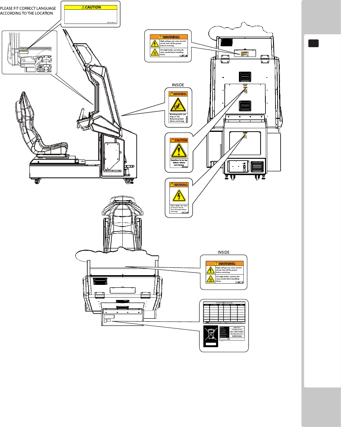
CONCERNING THE STICKER DISPLAY
This SEGA product has stickers attached describing the product manufacture No. (Serial No.) and Electrical
Specications. It also has a Sticker describing where to contact for repair and for purchasing parts.
When inquiring about or asking for repairs, mention the Serial No. and Name of Machine indicated on the Sticker.
The Serial Number indicates the product register. Identical machines could have different parts depending on the
date of production. Also, improvements and modications might have been made after the publication of this
manual. In order to ensure you order the correct parts, mention the Serial No. when contacting the applicable places.
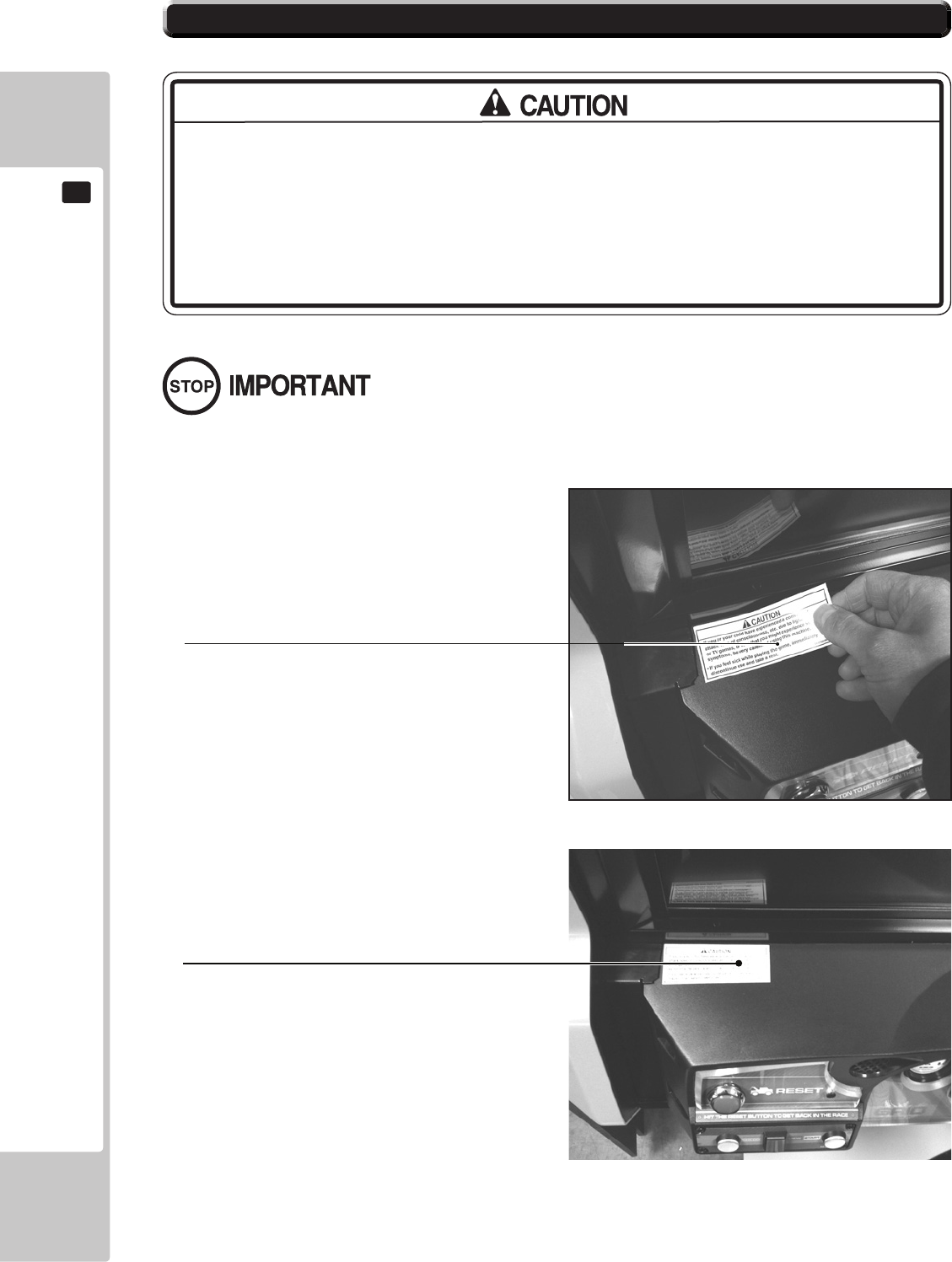
CONCERNING WARNING DISPLAYS
This SEGA product has warning displays on stickers, labels and/or printed instructions adhered/attached to or
incorporated in the places where a potentially hazardous situation could arise. The warning displays are intended
for accident prevention for customers and for avoiding hazardous situations relating to maintenance and servicing
work. Some portions of the cabinet contain high voltage and may cause accidents if touched. When performing
maintenance, be very careful of the warning displays. It is especially important that any complex repair and
replacement work not mentioned herein should be performed by those technical personnel who have knowledge of
electricity and technical expertise.
In order to prevent accidents, caution any customer ignoring the warnings to cease and desist immediately.
HANDLING PRECAUTIONS
3
1
If you or your child have experienced a convulsive attack, loss of
consciousness, etc. due to light stimulus or TV games, or fear that you
might experience such symptoms, be very careful of using this
machine.
If you feel sick while playing the game, immediately discontinue use
and take a rest.
4
PRECAUTIONS REGARDING INSTALLATION LOCATION
2
2 PRECAUTIONS REGARDING INSTALLATION
This product is an indoor game machine. Do not install it outside. Even indoors,
avoid installing in places mentioned below so as not to cause a fire, electric
shock, injury and/or malfunction.
Places subject to rain or water leakage, or places subject to high humidity in the
proximity of an indoor swimming pool and/or shower, etc.
Places subject to direct sunlight, or places subject to high temperatures in the
proximity of heating units, etc.
Places filled with inflammable gas or vicinity of highly inflammable/volatile
chemicals or hazardous matter.
Dusty places.
Sloped surfaces.
Places subject to any type of violent impact.
Vicinity of anti-disaster facilities such as re exits and re extinguishers.
Areas where the temperature exceeds the applicable temperature (ambient
temperature) range of 5 to 30 degrees centigrade.
LIMITATIONS OF USAGE
Be sure to check the Electrical Specifications. Ensure that this product
is compatible with the location's power supply, voltage, and frequency
requirements. A plate describing Electrical Specifications is attached to the
product. Non-compliance with the Electrical Specications can cause a re and
electric shock.
This product requires a breaker and earth mechanism as part of the location
facilities. Using the product without these can cause a re and electric shock.
Ensure that the indoor wiring for the power supply is rated at 15 A or higher (AC
single phase 100 V ~ 120 V area), and 7 A or higher (AC 220 V ~ 240 V area). Non-
compliance with the Electrical Specications can cause a re and electric shock.
Be sure to use an independent power supply equipped with an earth leakage
breaker. Using a power supply without an earth leakage breaker can cause an
outbreak of re if a power surge occurs.
Putting many loads on one electrical outlet can cause generation of heat and a
re resulting from overload.
When using an extension cord, ensure that the cord is rated at 15 A or higher (AC
100 V ~ 120 V area) and 7 A or higher (AC 220 V ~ 240 V area). Using a cord rated
lower than the specied rating can cause a re and electric shock.
PRECAUTIONS REGARDING INSTALLATION LOCATION
5
2
Securing a safe area for operation as described in this manual will ensure
safe operation for players and observers.
SEGA shall not be held responsible for damage or compensation for damage
to a third party, resulting from the failure to observe this instruction.
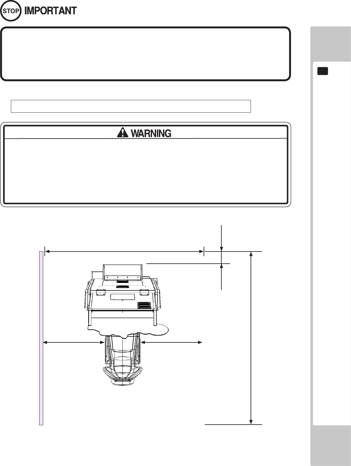
For the operation of this machine, secure a minimum area of 1.86m (W) x 2.73m (D).
Be sure to provide sufcient space specied in this manual. Do not allow objects
to block the ventilation ports. It can cause generation of heat and a re.
Sufcient space either side of the playing area must be allowed for the player to
enter or exit the game safely.
OPERATION AREA (SINGLE CABINET)
1860mm
2730mm
200mm
500mm830mm
6
PRECAUTIONS REGARDING INSTALLATION LOCATION
2
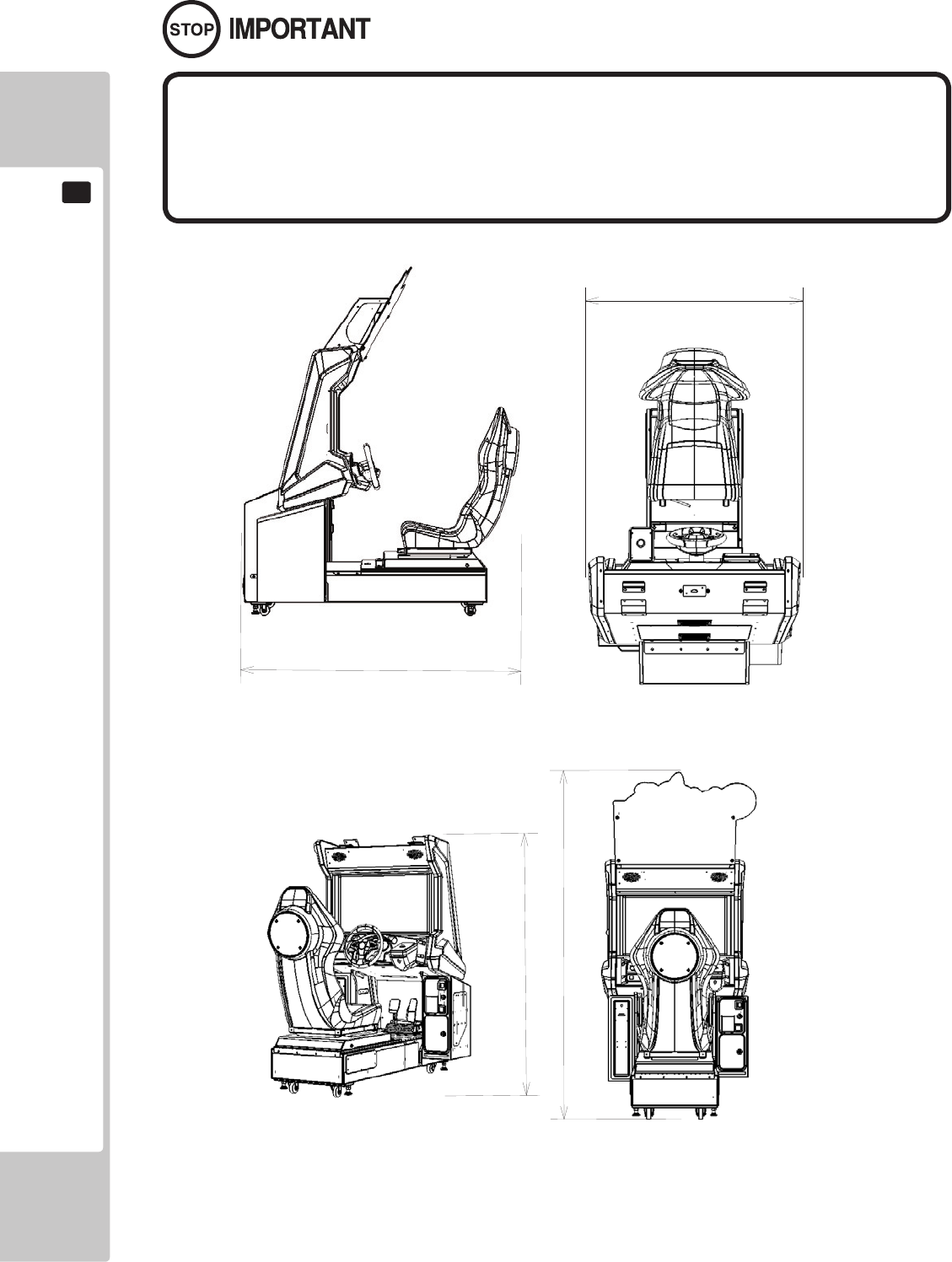
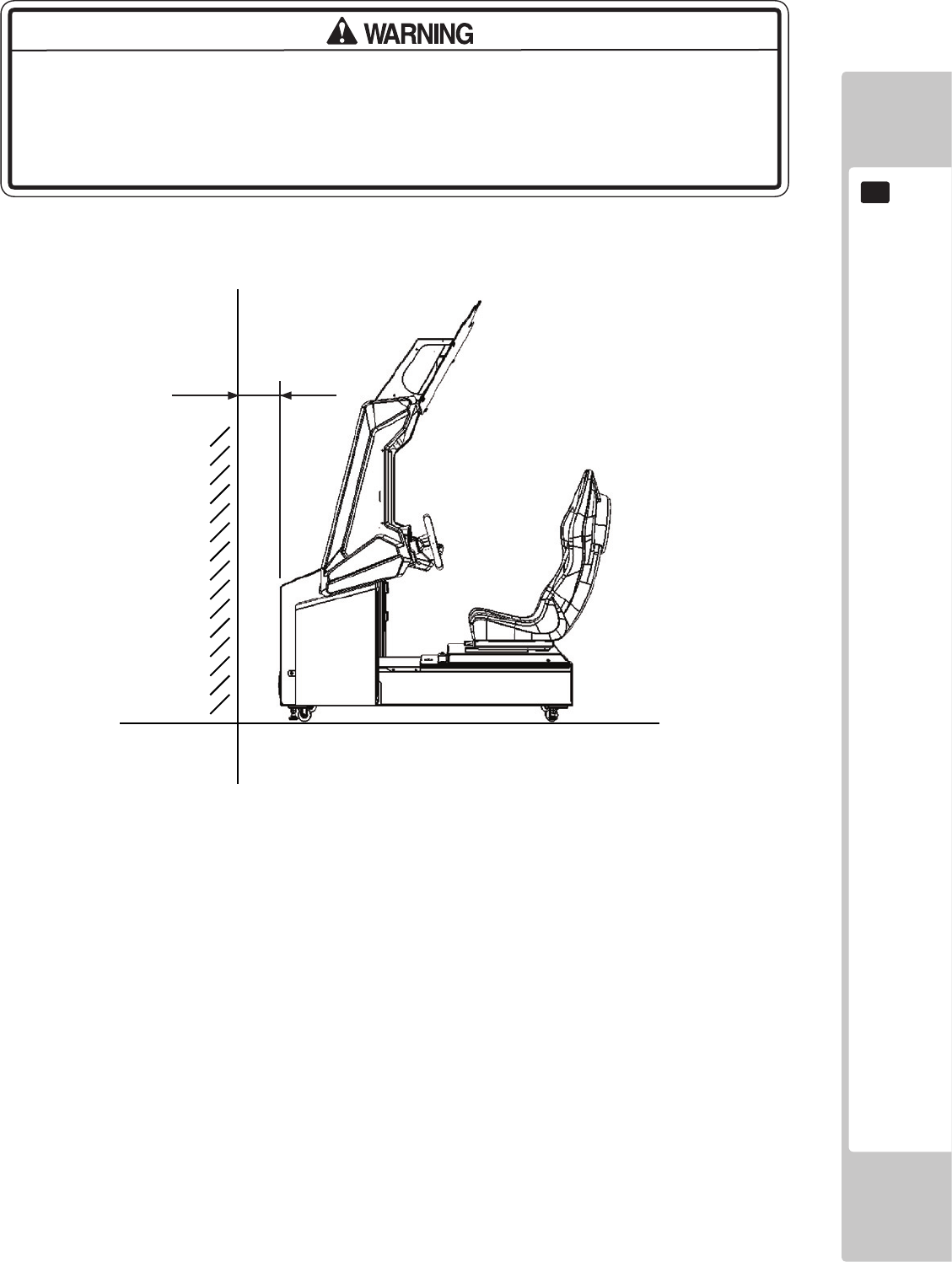
To install this product, the entrance must be at least 1.1m in width and 1.7 m
in height (without Assy Billboard) and 2.21m (with Assy Billboard).
Do not attempt to push/pull whilst holding onto the Assy Billboard. This may
result in part damage and or personal injury.
2207
mm
1610
mm
1700mm
1010mm
PRECAUTIONS REGARDING PRODUCT OPERATION
7
3
3 PRECAUTIONS REGARDING OPERATION
To avoid injury and trouble, be sure to pay attention to the behavior of visitors and players.
In order to avoid accidents, check the following before starting the operation:
• To ensure maximum safety for the players and the customers, ensure that
where the product is operated has sufcient lighting to allow any warnings to be
read. Operation under insufcient lighting can cause bodily contact with each
other, hitting accident, and/or trouble between customers.
• Be sure to perform appropriate adjustment of the display (LCD, Plasma, CRT
or Projector). For operation of this machine, do not leave monitor's ickering or
deviation as is. Failure to observe this can have a bad inuence upon the players'
or the customers' physical conditions.
• It is suggested to ensure a space allowing the players who feel sick while
playing the game to take a rest.
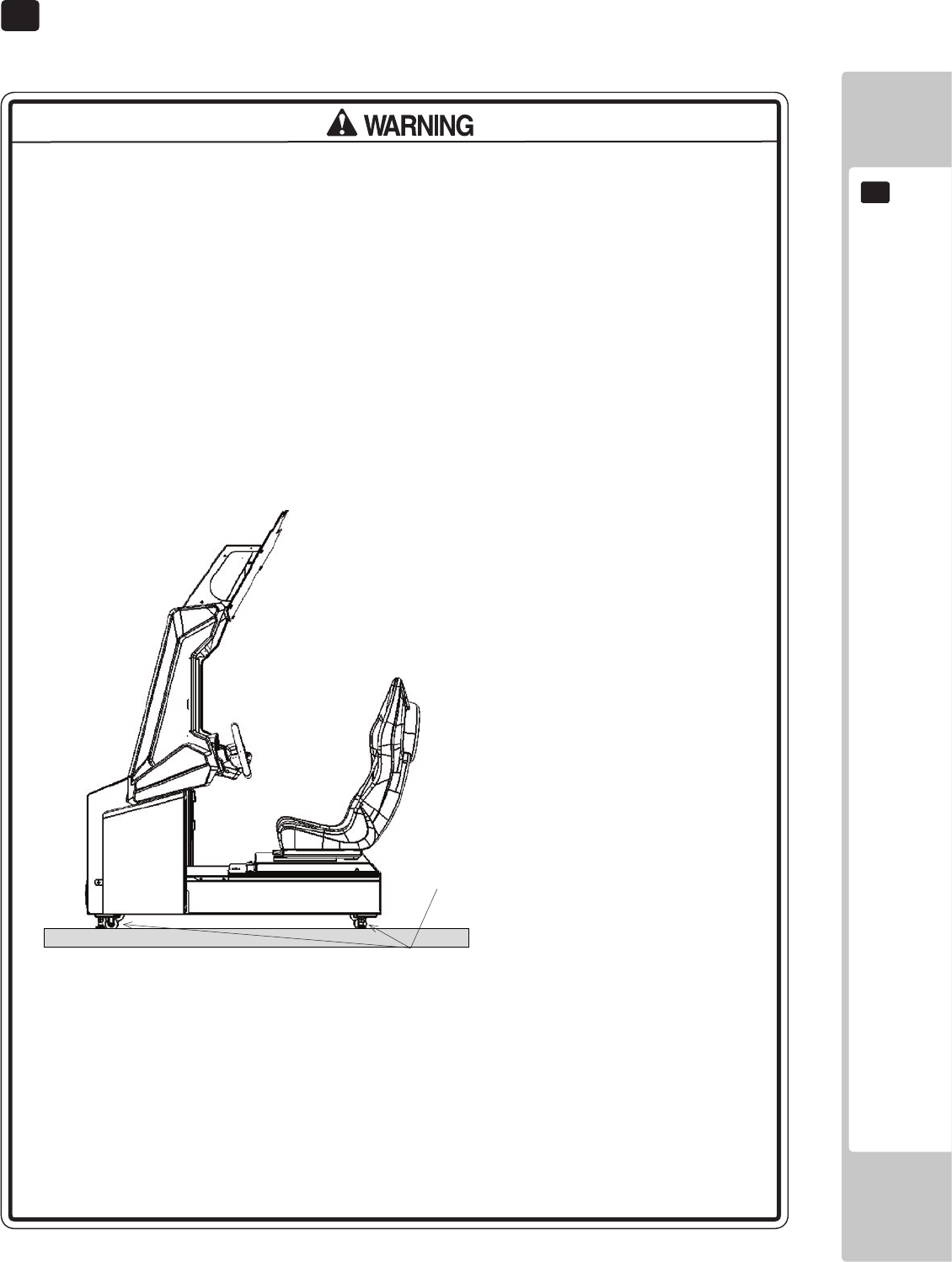
• Check if all of the adjusters are in contact with the surface. If they are not, the
Cabinet can move and cause an accident.
• Do not put any heavy item on this product. Items, if placed on this product
may fall and cause injury to the player / observer.
• Do not climb on the product. Climbing on the product can cause falling down
accidents. To check the top portion of the product, use a step ladder.
Each leg adjuster MUST be lowered so that the
casters are raised approximately 5mm off the
oor.

8
PRECAUTIONS REGARDING PRODUCT OPERATION
3
It is recommended that wet towels (paper towels) be provided.
• To avoid electric shock, ensure that all covers and panels are undamaged
and tted. Do not operate with covers removed.
• To avoid electric shock, short circuit and/or parts damage, do not put the
following items on or in the periphery of the product.
Flower vases, flowerpots, cups, water tanks, cosmetics, and receptacles/
containers/vessels containing chemicals and water.
• To avoid injury, be sure to provide sufficient space by considering the
potentially crowded situation at the installation location. Insufficient installation
space can cause making bodily contact with each other, hitting accidents, and/
or trouble between customers.
• Everyday when cleaning the Controller, inspect the controller and make sure
that there are no cracks in the surface, and that the fastening screws are not
loose. If the game is played with cracks or loose screws, it can cause injuries to
the player.
• Do not allow more than one person in any seat at any time. Do not allow adults
to play the game with a child sitting in their lap.
PRECAUTIONS REGARDING PRODUCT OPERATION
9
3
To avoid injury and trouble, be sure to constantly give careful attention to the behavior and manner of the visitors
and players.
• For safety reasons, do not allow any of the following people to play the game.
- Those who have high blood pressure or a heart problem.
- Those who have experienced muscle convulsion or loss of consciousness
when playing video games, etc.
- Those who have neck or spinal cord problems.
- Those who are intoxicated or under the inuence of drugs.
- Pregnant women.
- Those who are not in good health.
- Those who do not follow the attendant’s instructions.
- Those who cannot grasp the Control Unit securely because of immobility in
ngers, hands or arms.
- Persons who disregard the product's warning displays.
This product is intended for a single player only. Having two or more persons
simultaneously playing this product can result to injury to the player and possible
damage to the product.
• Even players who have never been adversely affected by light stimulus might
experience dizziness or headache depending on their physical condition
when playing the game.
Small children are especially likely to experience these symptoms. Caution
guardians of small children to keep watch on their children during play.
• Instruct those who feel sick during play to have a medical examination.
• To avoid injury from falls and electric shocks due to spilled drinks, instruct the
player not to place heavy items or drinks on the product.
• To avoid electric shocks and short circuits, do not allow customers to put
hands and ngers or extraneous matter in the openings of the product or small
openings in or around the doors.
• To avoid falls and resulting injury, immediately stop the customer from leaning
against or climbing on the product, etc.
• To avoid electric shock and short circuit, do not allow customers to unplug the
power plug without a justiable reason.
• Instruct the guardians of small children to keep an eye on their children.
Children cannot sense danger. Allowing small children to get near a player
who is playing the game could result in the children being bumped, struck or
knocked down.
DURING OPERATION (PAYING ATTENTION TO CUSTOMERS)
10
PART DESCRIPTIONS
4
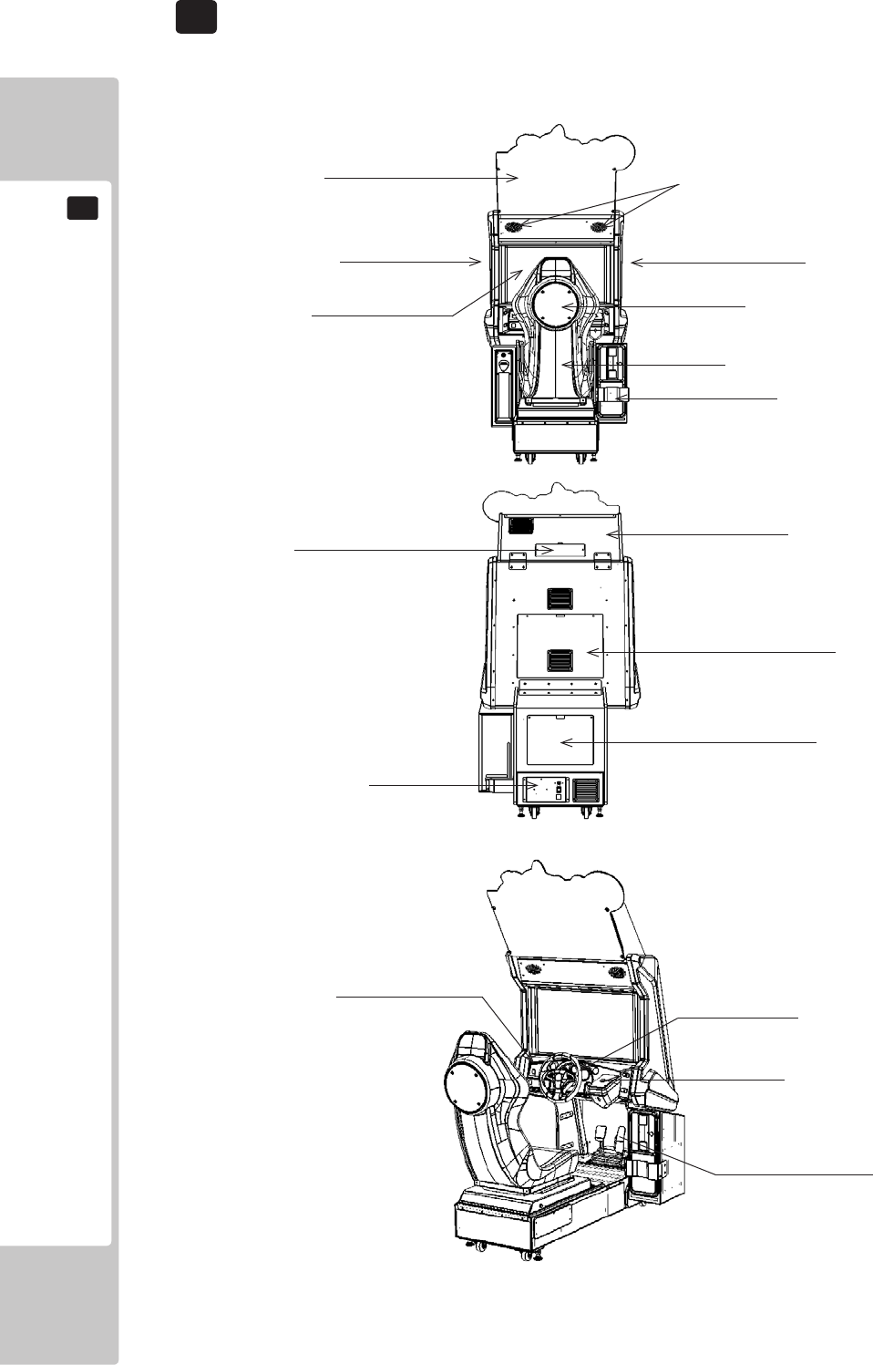
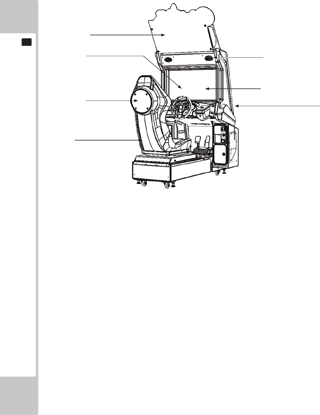
4 PART DESCRIPTIONS
Mon Cover R
Assy LCD Display Seat Woofer
Assy Coin Tower
Assy Seat
Mon Cover L
Speakers
Billboard Plate
Assembly Billboard
Service Door (Billboard)
Service Door (Mon Cabi)
Service Door (Base Box)
Assy AC Unit
Assy Control Panel
Start Button
Accel & Brake Assy
Steering Wheel
ACCESSORIES
11
5
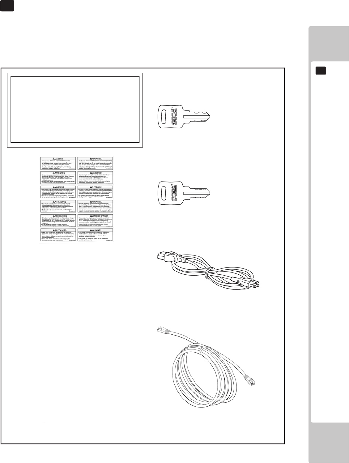
5 ACCESSORIES
Conrm that the accessories listed in the table below are present when setting up the product.
Accessories marked “Spare” in the note column are consumable items but included as spares.
DESCRIPTION: OWNER’S MANUAL
Part No. (Qty.):
420-0012UK(1)
Parts not labeled with part numbers are as yet
unregistered or cannot be registered. Be sure to handle
all parts with care, as some parts are not available for
purchase separately.
KEY MASTER
220-5575-01UK (2)
For operating/closing the doors
KEY
(2)
For the cashbox door
(Located inside the coin chute door at time of
shipment)
POWER CORD
LM1227 (1) <UK>
LM1226 (1) <EU>
For installation. See chapter 6.
Assy LAN Cable 150cm
600-7269-0150UK (1)
440-CS0186UK
Sticker C Epilepsy Multi (1)
12
ACCESSORIES
5
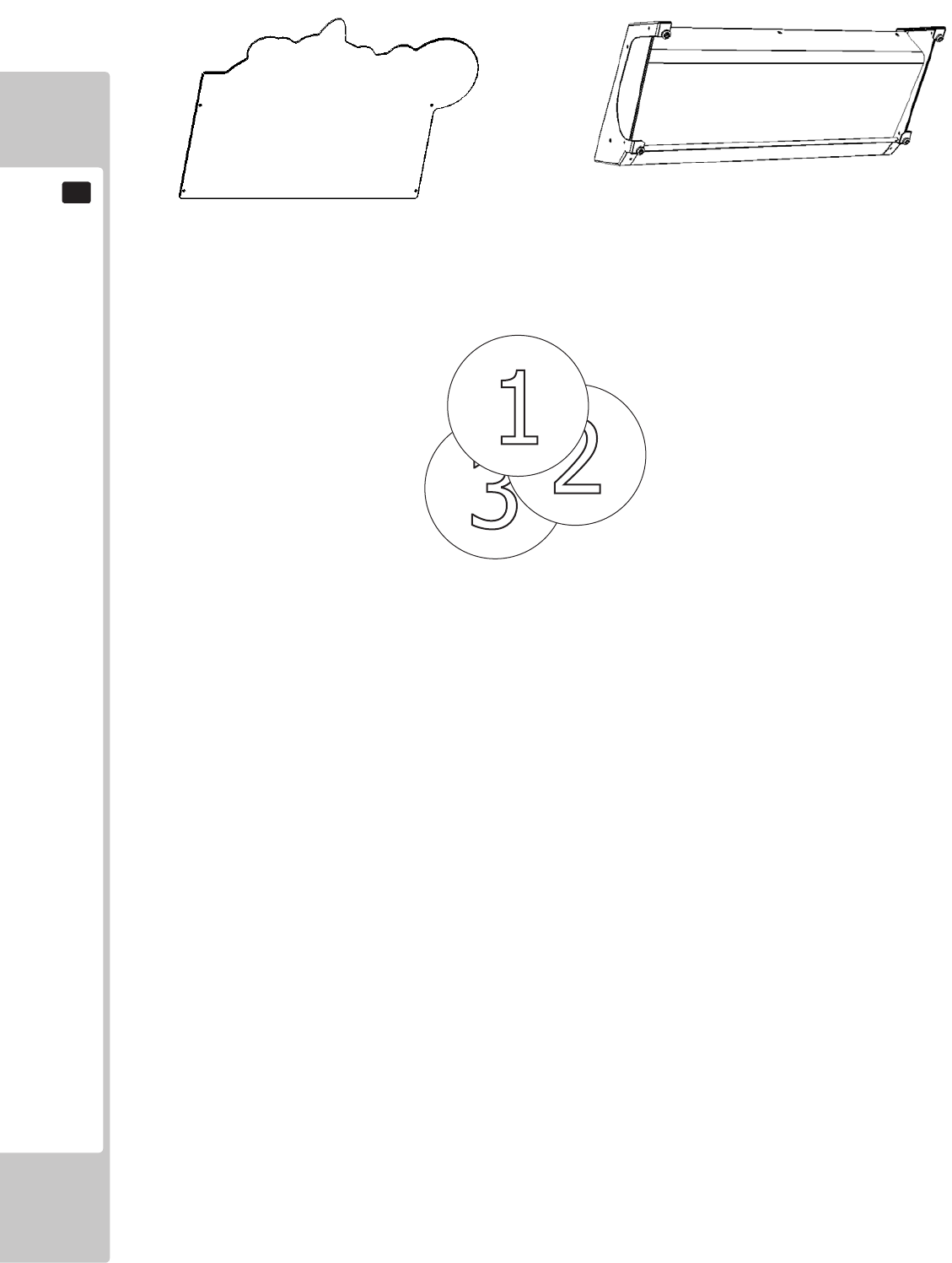
BILLBOARD PLATE
SSR-0507UK
For installation. See chapter 6.
ASSY BILLBOARD
SSR-0500UK
For installation. See chapter 6.
STICKER BILLBOARD INSERT No1-8
SSR-0507-BUK - No1 SONIC
SSR-0507-CUK - No2 TAILS
SSR-0507-DUK - No3 Dr EGGMAN
SSR-0507-EUK - No4 SHADOW
SSR-0507-FUK - No5 AIAI
SSR-0507-GUK - No6 AMY
SSR-0507-HUK - No7 AMIGO
SSR-0507-JUK - No8 BILLY HATCHER
For installation. See chapter 6.
ASSEMBLY AND INSTALLATION
13
6
6 ASSEMBLY AND INSTALLATION
• Perform assembly work by following the procedure herein stated. Failure to
comply with the instructions can cause electric shock.
• Perform assembly as per this manual. Since this is a complex machine,
incorrect assembling can cause an electric shock, machine damage and/or
improper functioning as per specied performance.
• When assembling, more than one person is required. Depending on the
assembly work, there are some cases in which working by one person alone can
cause personal injury or parts damage.
• Ensure that connectors are properly connected. Improper connections can
cause electric shock.
• Be careful not to damage the wires. Damaged wires may cause electric shock
or short circuit or present a risk of re.
• Do not unnecessarily push the display screen.
• This work should be carried out by site maintenance personnel or other
qualied professionals. Work performed by non-technical personnel can cause a
severe accident such as electric shock. Failing to comply with this instruction can
cause a severe accident such as electric shock to the player during operation. If
no one with proper technological expertise is available, request service from the
ofce indicated in this document or the point of purchase so as to ensure safety.
• Provide sufcient space so that assembling can be performed. Performing work
in places with narrow space or low ceiling may cause an accident and assembly
work to be difcult.
• To perform work safely and avoid serious accident such as the cabinet falling
down, do not perform work in places where step-like grade differences, a ditch,
or slope exist.
• This product does not use any connectors other than those connected to and
used by the game board when it leaves the factory. Do not needlessly connect
wires to unused connectors. This could lead to overheating, generation of smoke
and burn related injuries.
• Handle molded parts with care. Excessive weight or pressure may cause them
to break and the broken pieces may cause injury.
• To perform the operation safely and accurately you must use a safe, steady
footstool or stepladder. Working without this may lead to a fall and possible injury.
14
ASSEMBLY AND INSTALLATION
6
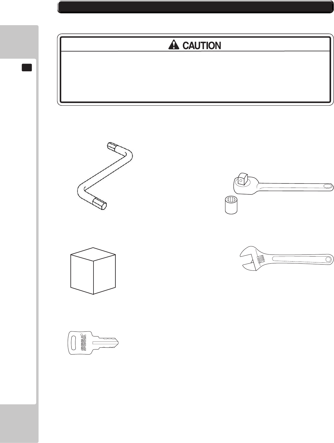
Tools required for installation
• Billboard weighs approximately 19 kg. Have at least 2 people during thisBillboard weighs approximately 19 kg. Have at least 2 people during this
operation. Working alone could result in personal injuries, etc..
• To perform work safely and securely, be sure to prepare a step which is in a
safe and stable condition. Performing work without using a step may lead to injury
of damage to components.
Allen Key (M5)
- Attaching Billboard Panel to Assy Billboard.
(Not Supplied)
Hex Driver or Wrench (M6)
- Attaching Assy Billboard.
Step or Ladders
- Aid in xing Billboard and Billboard Panel.
Adjustable Wrench
- Secure cabinet into position.
KEY
- Gain access to Coin Tower
6-1 INSTALLING THE CABINET
ASSEMBLY AND INSTALLATION
15
6
1
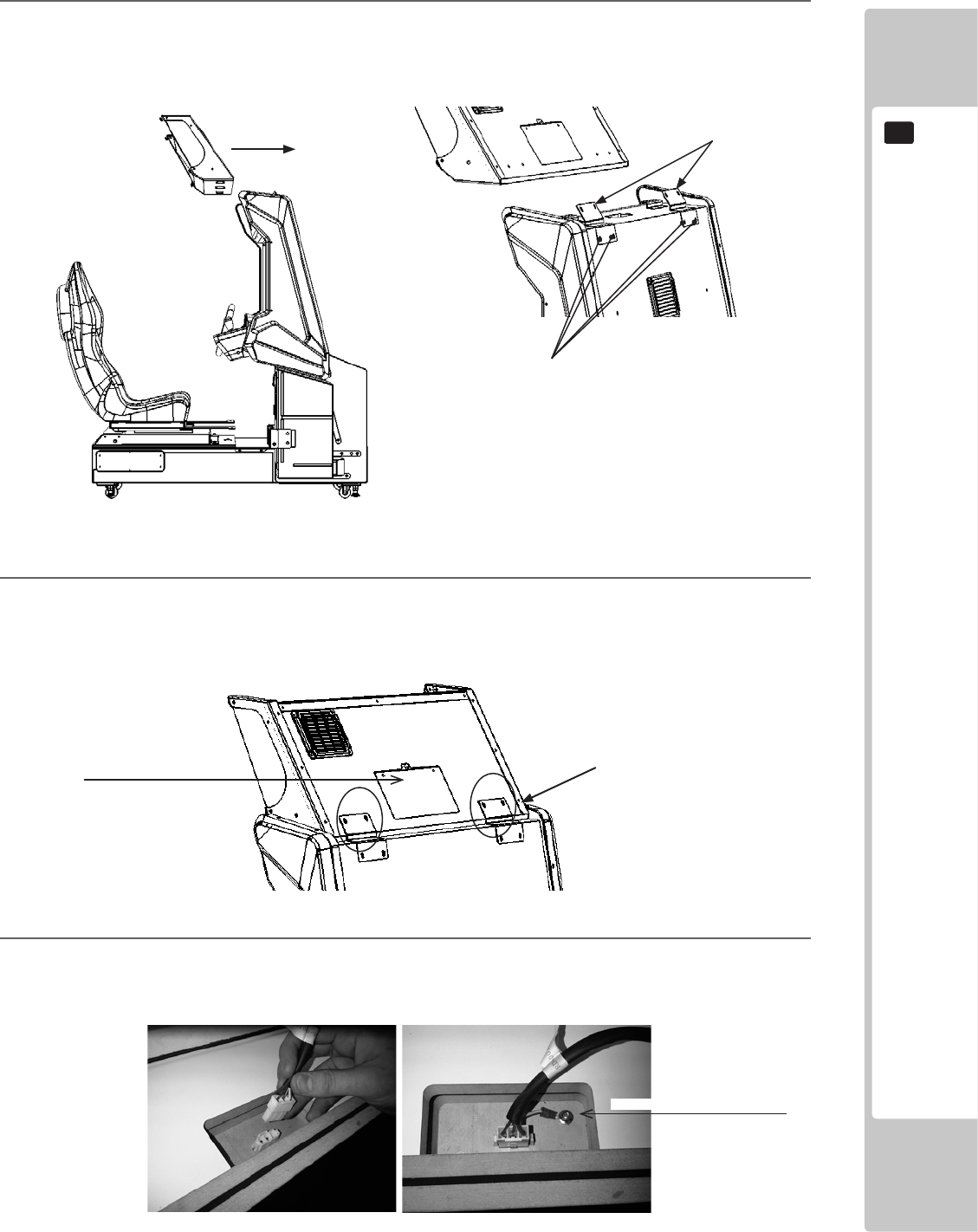
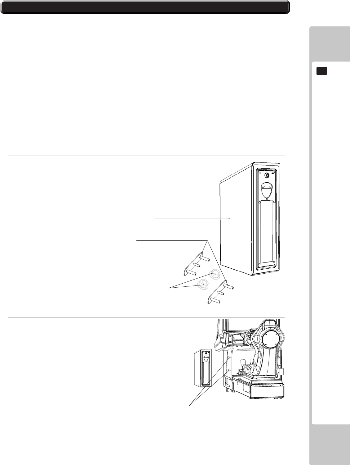
Fit 2x Billboard Holder (RD-2106UK) to the top of the Monitor Cab using 4x M6x20 Hex Bolt Black.
2
Lift and place the billboard on to the Monitor Cabinet from the front and gentle slide until contact with
Billboard Holders. Take care not to trap any wires in this process. Secure the Assy Billboard to the upper
xing points of the Billboard Holder Brackets using 4x M6x20 Hex Bolt Black.
3
Remove the Assy Billboard Rear Cover using a Phillips No1 Screwdriver and locate the Billboard Harness.
Connect the Billboard Harness to the Top of the Monitor Cabinet as shown.
Secure using M6x20 Hex Blt Blk
Billboard Holder
(RD-1206UK)
Fixing Points
6-1-1 INSTALLING THE ASSY BILLBOARD
Billboard Rear Cover
EARTH - M4 NUT FLG PAS
16
ASSEMBLY AND INSTALLATION
6
1
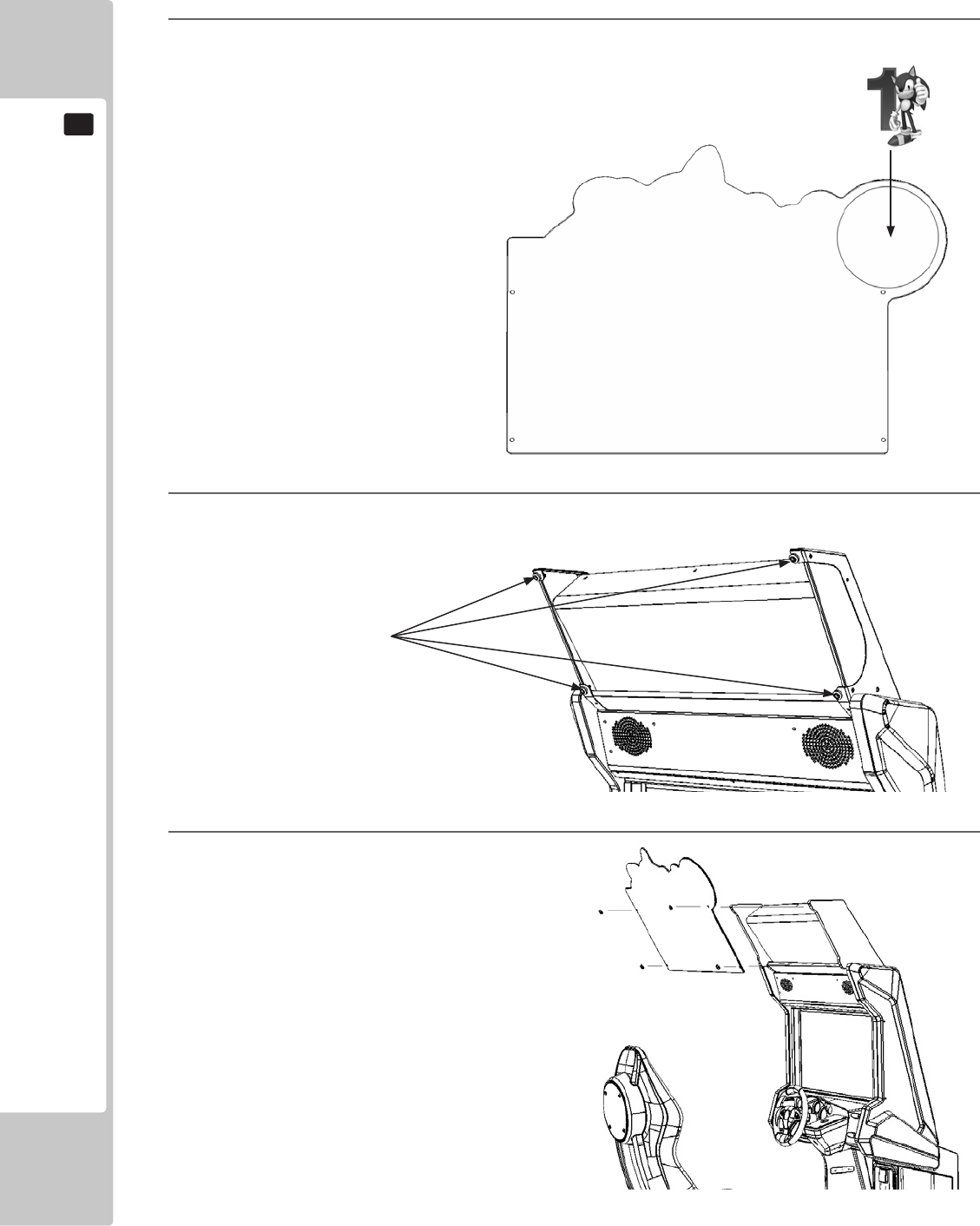
The individual character numbers are self adhesive and are applied onto the back
face of the Billboard Plate.
Take care when handling the Character Number Stickers as the adhesive is applied
to the printed surface it is possible
to leave marks or ngerprints. Wash
hands before applying or use a
surgical type glove.
2
Locate and remove the 4 sets of xings from the Billboard Plate xing points
3
Fix the Billboard Plate into position using the
xings removed in step 2.
Remove xings before tting
the Billboard Plate.
6-1-2 INSTALLING THE BILLBOARD PLATE
ASSEMBLY AND INSTALLATION
17
6
1
Ensure that all parts are present before starting work.
2
Offer the Ticket Vend Unit up to the Cabinet
This game has the option to install a Ticket Unit. The Ticket Unit can be set up to dispense an
amount of tickets to the winner/loser of a race.
Please see section 9 / Game Test Mode / Game Adjustments for full operation settings of the
Ticket Unit.
If you would like to purchase the Ticket Option, please contact your distributor or your local
SEGA Office.
SSR-0700UK - ASSY TICKET VEND UNIT
RD-1214UK - CCT HOLDER X2
050-H00800 - M8 NUT HEX FLG PAS
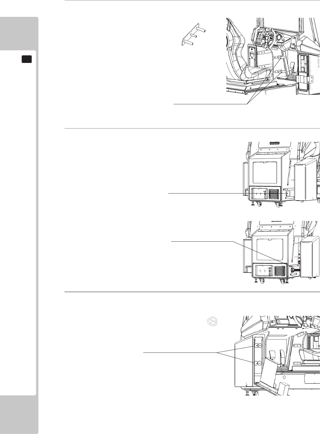
Remove the (6) blind hole coves from the LHS of the cabinet
6-2 INSTALLING THE TICKET BOX (OPTION)
6-2 INSTALLING THE TICKET BOX (OPTIONAL)
18
ASSEMBLY AND INSTALLATION
6
3
Feed both CCT HOLDERS (RD-1214UK) through the cabinet until the threads of the plate appear through
the other side.
4
Before offering the TICKET VEND UNIT up to the cabinet, make sure all connections (including the Earth)
are correctly made between devices.
5
Unlock and open the TICKET VEND UNIT door and carefully offer up to the cabinet. Whilst holding the
TICKET VEND UNIT firmly in place, secure where indicated using the (4) M8 hex nuts provided.
Feed both CCT HOLDERS through cabinet
Secure using the (4) M8 Hex nuts provided.
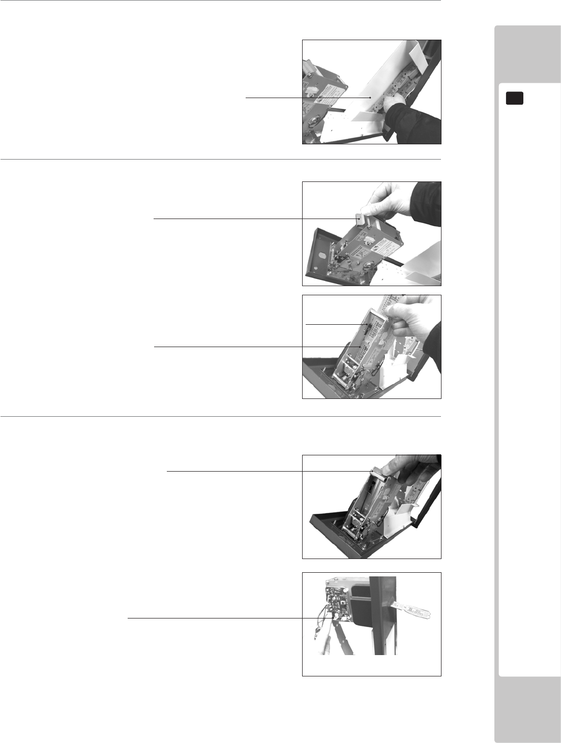
Unscrew the (4) Phillips screws and remove
the Connector Cover Plate
Connect the harness and EARTH from the
TICKET VEND UNIT to the Connector Plate.
Note:
Any excess harness can be pushed into the
Ticket Unit Housing to prevent trapping.
ASSEMBLY AND INSTALLATION
19
6
6
Place the Tickets into the TICKET HOLDER.
7
Feed the Tickets into the TICKET MECH.
8
Press the TEST button on the side of the VEND MECH PCB to check that the Tickets run smoothly through
the unit.
Unclip and remove the Ticket retainier
Ticket Holder
Feed the tickets into the mech, making sure
that the ticket passes through the sensor.
Once the tickets have been fully inserted into
the mech, replace the ticket retainer to secure
tickets into position.
Press the TEST button on the PCB to draw tickets through the
mech and out of the door.
Tear off any excess tickets
Sensor
20
ASSEMBLY AND INSTALLATION
6
• Make sure that all the adjusters contact the oor. Otherwise the cabinet could
move, causing an accident.
• Provide a ventilation space at least 20cm wide behind the cabinet. There are
ventilation holes on the back of the cabinet. Do not block the ventilation holes.
Doing so could trap heat inside resulting in re. It could also result in equipment
damage or cause parts to become exhausted prematurely.
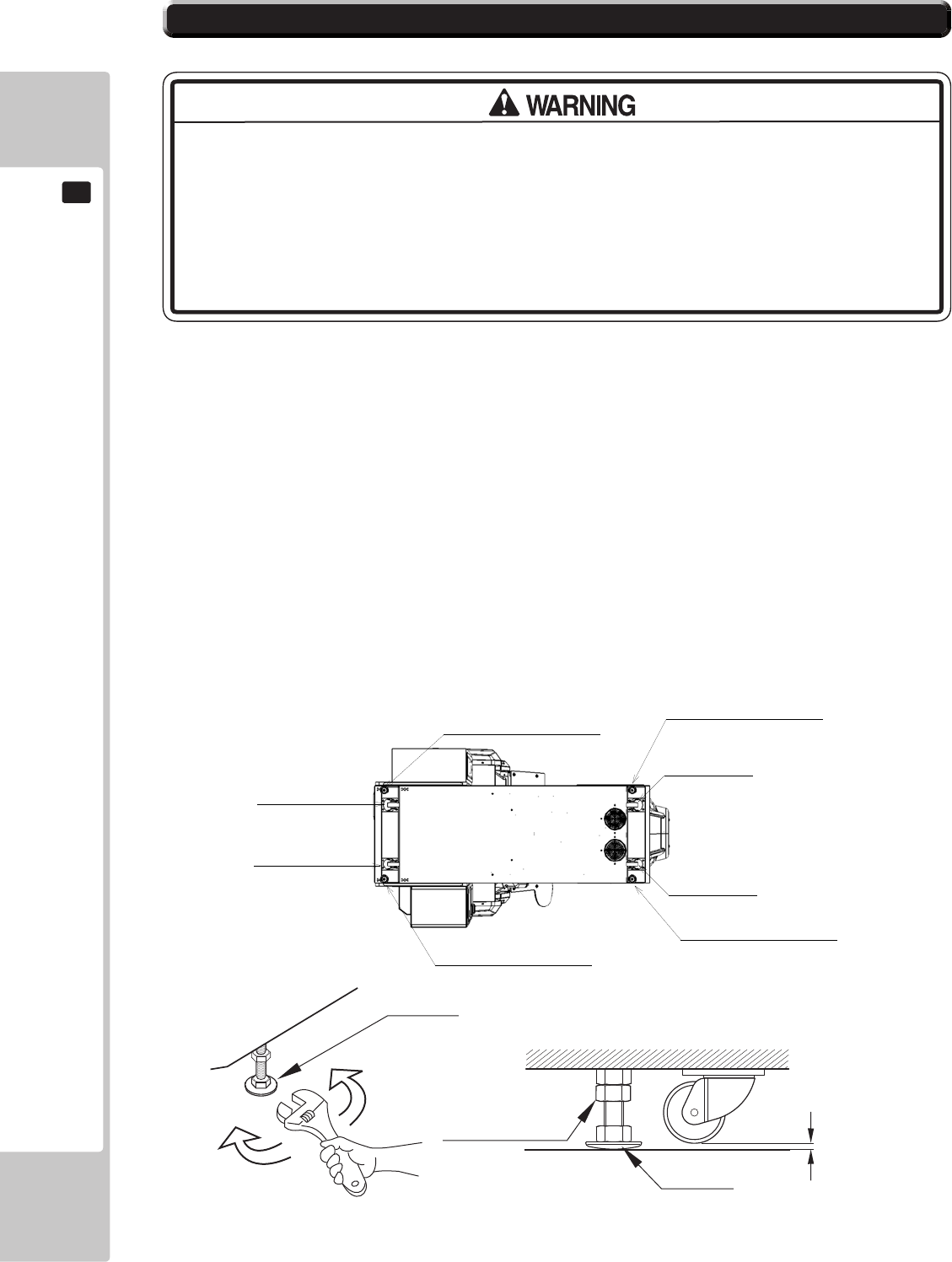
The product is equipped with 4 casters and 4 adjusters.
When installation position / site has been determined, have the adjusters come in direct contact with the floor.
Establish a gap of about 5 mm between the oor and the casters and adjust the unit so that it will remain level.
1 Move the product to the installation site.
2 Bring the adjusters into direct contact with the oor. Use a wrench to align the height of the adjusters until the
cabinet is perfectly level.
3 After setting, turn adjuster nuts upwards to tighten them and secure adjuster heights.
Approx. 5 mm
ADJUSTER
Fasten the nuts in an
upward direction.
ADJUSTER
CASTER
6-3 FIXATION TO SITE
Castors
Castors
Castors
Castors
Leg Adjusters
Leg Adjusters
Leg Adjusters
Leg Adjusters
ASSEMBLY AND INSTALLATION
21
6
200mm
• Provide a ventilation space at least 20cm wide behind the cabinet. There are
ventilation holes on the back of the cabinet. Do not block the ventilation holes.
Doing so could trap heat inside resulting in re. It could also result in equipment
damage or cause parts to become exhausted prematurely.
Leave a 200mm gap for ventilation
22
ASSEMBLY AND INSTALLATION
6
• Use the power supply equipped with an earth leakage breaker. Use of power
supply without such a breaker could result in re if there is a current leakage.
• Have available a securely grounded indoor ground terminal. Without proper
grounding, customers could be electrocuted and product operations might not
always be stable.
• Do not expose the power cord or ground wire. If these are exposed, customers
could stumble over them, for instance, and easily damage them. Additionally, if
these lines are damaged, there could be a risk of electrical shock or short circuit.
Set these lines at locations where they will not interfere with customer trafc, or
attach covers to them.
• After laying out the power cord on the floor, be sure to always protect it. If
the power cord is left exposed, it can easily be damaged, resulting in electrical
shock.
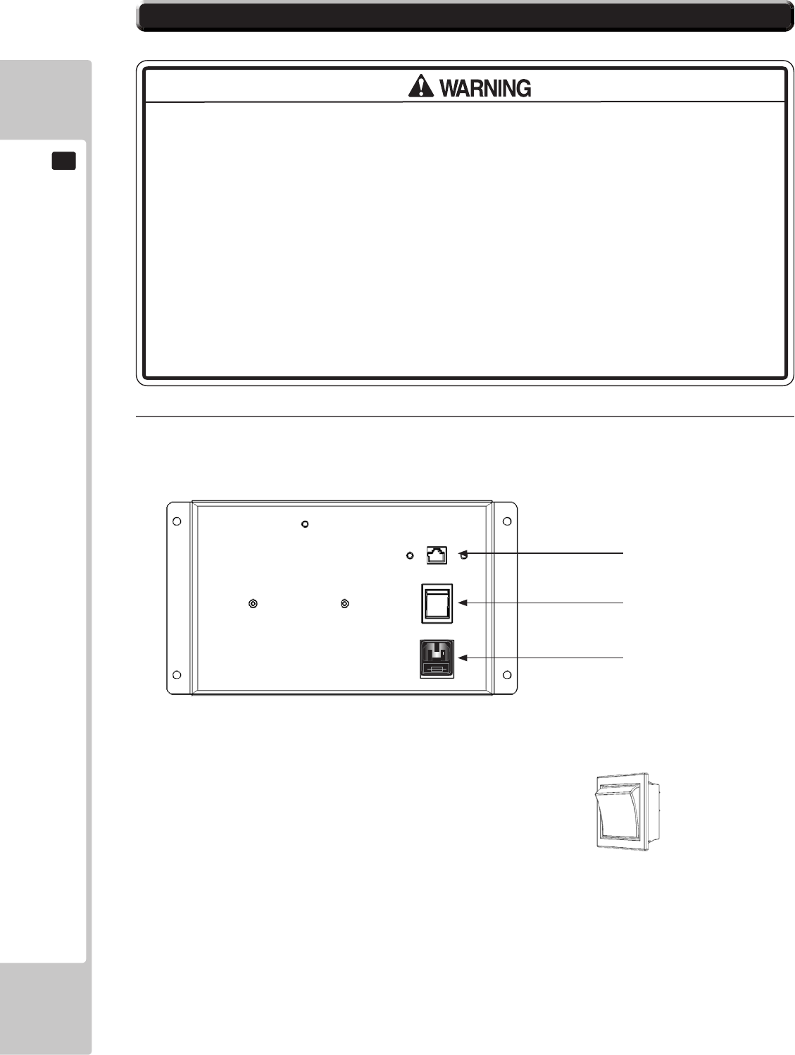
1
Conrm that the main switch is at OFF.
USE ONLY 250V FUSES
Mains Switch shown in
OFF position
Lan Network Connector
Mains ON/OFF Switch
IEC Inlet
6-4 POWER SUPPLY AND OTHER CONNECTIONS
ASSEMBLY AND INSTALLATION
23
6
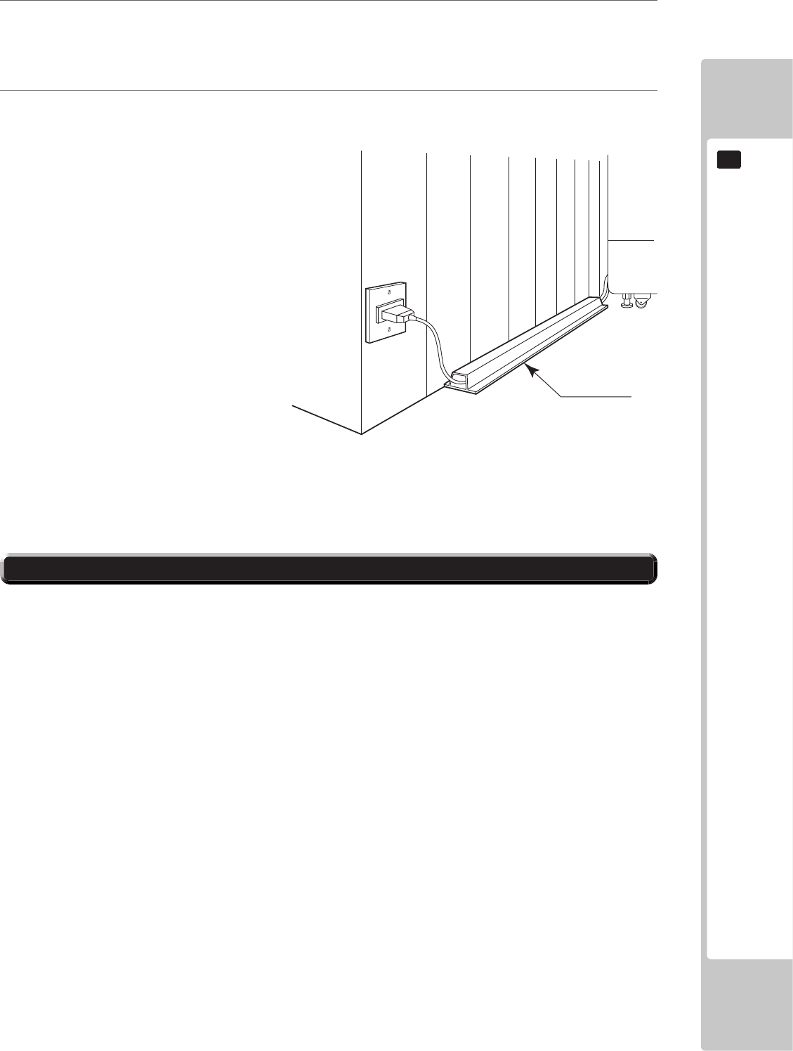
2
Fully insert the power cord connector on the side opposite the power plug into the AC unit IEC inlet. InsertInsert
the power cord plug into the outlet.
3
The power code is laid out indoors. Protect the power cord by attaching wire cover to it.
WIRE COVER
Set the main switch of the AC unit to ON and engage the power.
When you turn on the power, the billboard uorescent lights will come on.
After the SEGA LOGO start up screen is displayed on the LCD screen, the Advertise (Attract) Mode will
start.
The decorative LEDs within the seat and the side covers will scroll through a variation of colours.
Start up sounds are output from the speakers on the left and right of the cabinet together with display of the
SEGA startup screen.
Even when the power source has been cut off, credit count, ranking data, game settings and bookkeeping
data are kept stored in the product. However, fractional coin counts (inserted coins that do not amount to one
credit) and bonus adder counts are not kept.
6-5 TURNING ON THE POWER
24
ASSEMBLY AND INSTALLATION
6
Billboard illumination
Audio output
Attract Mode - Game
LED / Audio output
Seat Illuminates
SEGA logo
COMPONENTS WHICH CHANGE STATE WHEN POWER IS APPLIED
Side Covers Illuminate

ASSEMBLY AND INSTALLATION
25
6
In the test mode, ascertain that the assembly has been made correctly and IC Board is satisfactory.
In the test mode, perform the following test: (refer to chapter 9).
9-3-2 INPUT TEST
This menu is used to test the system inputs such as steering, pedals and buttons. To implement the test, press each
device that is listed and check the results on screen.
9-3-3 OUTPUT TEST
This menu is used to test the system oututs such as Lamps and LED.
9-9 COIN SETTINGS
As this system utilises a Credit Board PCB, it is important that the setting remain 1 COIN 1 PLAY. Deveation from
this setting when using the Credit Board PCB can result in unusual credit outputs.
9-11 NETWORK TEST
Apply and congure the network of each cabinet (only appiles if 2 or more cabinets are linked).
9-3-6 CALIBRATION TEST
This test is required to calibrated both steering mechanism and control pedals. This procedure is always carried out
at the factory before dispatch. However, certain conditions can have an effect on calibration and it is recommended
that re-calibration be carried out at point of installtion.
6-6 CONFIRMATION OF ASSEMBLY
26
ASSEMBLY AND INSTALLATION
6
• The operator MUST apply the Epileptiform Seizure Label to this product. Failing
to apply this label may result in the player/observer suffering from a photosensitive
seizure. Warning the potential player/ observer of this before the start of a game
may prevent such accidents.
• It is also important to apply the correct language label for each location. There
are nine (9) different language labels - please apply the label which matches
your location.
Application of any warning labels must be placed in a location which is easy for the player/observer to read.
Please follow the instructions below and apply the label in the location stated.
The Epileptiform Seizure label is supplied in 9 different
languages. Please choose the label which matches your
language location.
Apply the label to the top left hand corner of the Control
Panel. This location is unobstructed and can be easily
read by players and observers alike.
6-7 APPLYING WARNING LABELS (EPILEPTIFORM SEIZURES)
PRECAUTIONS WHEN MOVING THE MACHINE
27
7
7 PRECAUTIONS WHEN MOVING THE MACHINE
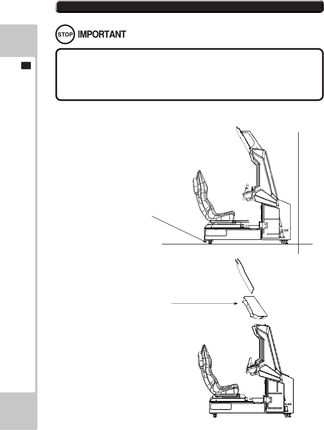
• When moving the cabinet, do not grip or push the Billboard Plate. Doing so
could deform or damage the part.
• If moving through a door or place with a low ceiling such as an elevator, you
should take apart the billboard and billboard plate.
• Always disconnect the power cable before moving the product. If it is moved
with the power cable connected, the cable could be damaged, causing re or
electric shock.
• To move the unit over the floor, pull in the adjustors and have the casters
contact the oor. While moving the unit, be careful that the casters do not roll over
the power cord or the ground wire. If cord or wire is damaged, there could be
electrical shocks and/or short circuits.
• When crossing a sloped or stepped area, always have the machine travel
lengthways. Travelling with the machine in a sideways position could result in the
machine falling over onto its side. Always use a minimum of two people working
together plus lifting apparatus to accommodate slopped areas or stairs.
• To lift up the cabinet, hold it at the bottom at the designated lifting points. If you
hold it anywhere else, the weight of the cabinet could cause damage to parts or
attachments, resulting in injury.
• Do not push the cabinet from the side when moving. Pushing from the side as it
may result in the cabinet falling over.
28
PRECAUTIONS WHEN MOVING THE MACHINE
7
Ensure that the casters come
into contact with the oor
before moving.
• When moving the cabinet, do not grip or push the Billboard Plate. Doing so
could deform or damage the part.
• If moving through a door or place with a low ceiling such as an elevator, you
should take apart the billboard and billboard plate.
Detailed instructions for removing the Assy Billboard and Billboard Plate can be found in Chapter 6 of this manual.
Please follow these instruction in reverse order for removal.
Remove the Billboard and
Billboard Plate when transporting
the machine in and out of
buildings or when passing through
areas with low ceilings.
7-1 PRECAUTIONS WHEN MOVING FROM SITE

GAME DESCRIPTION
29
8
8 GAME DESCRIPTION
GameOverview
Races in SONIC & SEGA ALL-STARS Racing Arcade are against the CLOCK and OTHER OPPONENT CARS.
Each game mode features a RACE TIMER continually counting down the remaining play time which can be
increased by starting a new lap on the track that is being raced upon.
There are several game modes within SONIC & SEGA ALL-STARS Racing Arcade. In addition to choosing either
‘Multiplayer’ or ‘Single Player’, players have 3 different Game Types to choose from in ‘Single Player’.
Single Race
Time Trials
Grand Prix
The game can be played upon a linkable network of up to 8 players. All players in a network can share highscores
and ghost cars
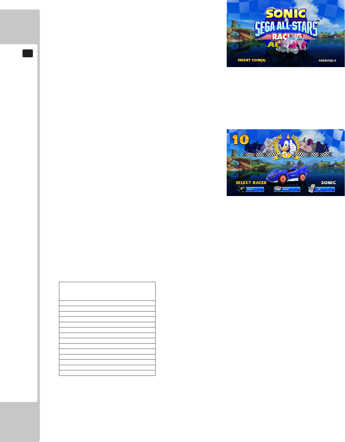
Game Selection
WHEN THE MACHINE IS IN CREDIT AND THE START BUTTON IS PRESSED, THE FOLLOWING GAME
SCREEN IS DISPLAYED, INDICATING THE GAME PLAY AVAILABLE.
Whether a cabinet is not linked up to any other cabinets, or if it is linked up with multiple cabinets, the rst action of
the player is to select whether to enter into a Multiplayer or Single Player game. The default selection is Multiplayer,
so if the game is left to time out on this screen, a Multiplayer Lobby will be created where other players can then
join. This only occurs if the cabinet is linked to other cabinets however. If it is not linked to any others, the player
will automatically be taken into a single player game. If the player wants to enter into a Single Player game, they
must hold down the DRIFT PEDAL in order to be taken to the Single Player Game Mode Select Screen.
During this selection sequence, a COUNTDOWN is displayed in the middle of the screen. If the player does not
hold down the DRIFT PEDAL to enter a Single Player game, the game will automatically set up a Multiplayer
Lobby once the time on the countdown has run out, as long as the cabinet is linked together with other cabinets.
If the player has entered into a Single Player Game, they will have the choice of choosing either SINGLE RACE,
TIME TRIALS or GRAND PRIX.
8-1 GAME OUTLINE

30
GAME DESCRIPTION
8
The default selection is SINGLE RACE and this can be changed by moving the ‘Steering Wheel’ either left or right.
When the desired Game Mode is displayed the player can make their selection by pressing the ACCELERATOR
pedal or START button to conrm their choice. A COUNTDOWN timer is also displayed in the top left corner of the
screen. If the timer is left to run out, whichever Game Mode is highlighted at this time will be automatically selected
and the game will advance to the next stage; Character Select.
GRAND PRIX – 1 PLAYER
Grand Prix is a single player race against AI opponents over
a sequence of tracks. This mode has three races which are
always raced in the same order with the easiest track being
rst and the hardest track being last.
Progress is maintained by completing a lap on the selected
track which acts as a checkpoint, adding on a set amount
of time to the COUNTDOWN timer displayed in the top
middle of the screen. The time handed out at each of these
laps/checkpoints becomes smaller on a harder difficulty
setting.
Upon completing a race, if the player nishes in the top 3 they will automatically be moved on to the next race
which will have a higher difculty.
Depending on what the Grand Prix settings have been set as in the GAME ASSIGNMENTS screen in the Test
Menu, the following actions will occur if the player runs out of time while racing on any of the tracks or fails to
nish within the top 3:
With GRAND PRIX set to ENABLED: If a player fails to nish in the 1st race they will not be able to continue and
will be sent to the Game Over screen. If they fail to nish in the 2nd or 3rd race, they will have the option to retry
the track if they insert a credit. If the player nishes any of the races in 4th position or below, they will be given the
option to retry the track if they insert a credit. If a credit is not inserted to continue in either scenario, the player will
be sent to the Game Over screen.
With GRAND PRIX set to DISABLED: If a player does not nish within the top 3 on any track, they will be taken
straight to the Game Over screen. There is no option to retry the race by inserting a credit.
With GRAND PRIX set to ENABLED ON CREDIT: If a player fails to nish in the 1st race they will not be able
to continue and will be sent to the Game Over screen. If they fail to nish on the 2nd or 3rd race they will be able to
insert a credit top retry that race. If the player nishes within the top 3 in the race, they will have to insert a credit to
be able to continue on to the next race within the Grand Prix.
The tracks that are raced on in Grand Prix are:
SUNSHINE TOUR
TURBINE LOOP
SANDY DRIFTS
During each track, the game will record the player’s total time for that race. At the end of a successfully completed
Grand Prix, the total time from all three tracks is added together, and the player is given a complete Total Time for
the Grand Prix. If the total time achieved in that Grand Prix is among the top 10 times previously recorded on the
cabinet or series of linked cabinets, the player will be prompted to enter a 3 letter name that will be entered into the
High Score Table (HST) for Grand Prix.
In completing all three tracks in Grand Prix by finishing within the top 3, the player will be rewarded with a
completion sequence. The player will then be shown the Credits sequence for the game during the completion
sequence.

GAME DESCRIPTION
31
8
SINGLE RACE – 1 PLAYER
Single Race features a race over multiple laps of a single track against a grid of 7 opponent cars. When a Multiplayer
Race is started, this also takes place over a single race on one track, with 7 opponent cars once again present. Any
positions which are not lled by human players will be lled by AI controlled racers when the race begins. There is
no scoreboard entry in Single Race,
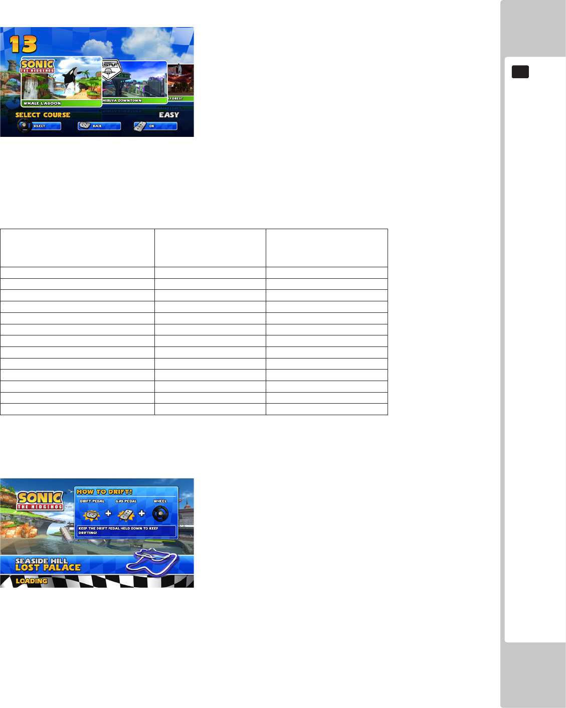
There are ten tracks to pick from in Single Race. These range in difculty from Easy to Medium to Hard, with each
track displaying what difculty they are. The tracks available in Single Race are:
Whale Lagoon
Shibuya Downtown
Outer Forest
Pinball Highway
Rampart Road
Dark Arsenal
Jump Parade
Lost Palace
Highway Zero
Bingo Party
TIME TRIALS – 1 PLAYER
Time Trials features a race over multiple laps of a single track where the aim is for the player to set the fastest lap
time possible. It is a solo race with no opponent cars present, and no weapon items available other than a High Speed
Shoe which the player receives one of at the start of each new lap.
A Ghost Car will also be on the track. This will be a record of the currently held top lap time on that track and will
show the race that the player had when that time was recorded along with the character that they used.
The fastest lap time that the player achieves in the race
will be recorded. If the lap time achieved in that race
is among the top 10 times previously recorded on the
cabinet or series of linked cabinets, the player will be
prompted to enter a 3 letter name that will be entered into
the High Score Table (HST) for that track.
32
GAME DESCRIPTION
8
MULTIPLAYER – 2 TO 8 PLAYERS
When starting up a Multiplayer Single Race, the players
are rst asked to select a character to represent them in the
race before they are taken to the Track Select. Players are
not able to select the same character as one another. Once a
character has been selected, any other player will be unable
to select that character. There is no scoreboard entry in
multiplayer races.
In a multiplayer game, Track Selection is decided upon by
a voting system. Each player within the game will be given
their choice of what track to select. Once all players have
selected a track, whichever track had the most votes will be the one that the players will then race on. In the case of
a tie, the track that is the easiest in difculty of the ones voted for will be the one that is raced on.
The race timer is added to whenever the player (or leading player in the case of link play) begins a new lap. In the
case of Time Over, there are no continues.
Character Selection
The next choice for the player after they select the Game
Mode is to select which Character to use on the track that
they will race on. SONIC & SEGA All-STARS Racing
Arcade has a total of 13 characters selectable with one
secret character also available. Turning the Steering
Wheel left and right will enable the player to see each of
the characters that are available to be selected. When the
desired character is displayed, the selection can be made by pressing either the Gas pedal or the Start button.
During this selection sequence, a COUNTDOWN timer is displayed in the top left hand corner of the screen. If
the player does not make a selection during this time, when the timer reaches zero, the character that is currently
highlighted will be automatically selected and the game will advance to the next stage; Track Select, or if the player
is in Grand Prix, the player will be taken straight to the rst race.
All the characters are available across all the game modes. The list of which characters are available in the game can
be found in the table below:
CHARACTER
SONIC
AIAI
BILLY HATCHER
AMIGO
ULALA
BEAT
B.D. JOE
RYO
RYO (FORKLIFT)*
JACKY & AKIRA
DR. EGGMAN
SHADOW
AMY
TAILS
A secret character (Ryo Forklift) is available in all game modes and can be unlocked by performing the following
actions:
If the player holds down both the Drift Pedal and Item Button on the steering wheel when pressing the Start button
to begin a game, the Ryo Forklift character will become available on the Character Select screen. Players will not be
able to use both versions of Ryo in a Multiplayer race. Only one version of the character can be used.
GAME DESCRIPTION
33
8
TRACK SELECTION
The next choice for the player after selecting their Character is to select which Track to Race on. (In Grand Prix,
the tracks are automatically selected for the player). SONIC & SEGA ALL-STARS Racing Arcade features a total
of 13 tracks though not all tracks are available in every Game Mode. Turning the ‘Steering Wheel’ left and right will
change the selected track and allow the player to view
each track that is selectable in the game mode that is
being played. When the desired track is displayed, it can
be selected by pressing either the Gas pedal or the Start
button to conrm the choice.
During this selection sequence, a COUNTDOWN timer
is displayed in the top left corner of the screen. If no
selection has been made when the timer runs out, the
track that is currently highlighted at that point will be
automatically selected, and the player will be taken to the
loading screen of the race.
Single Race contains 10 tracks. Grand Prix contains 3 tracks which are raced in the same order each time as the
player progresses through the game mode.
The table below shows what Tracks are available to select from for each of the Game Modes.
Track Grand Prix
Single Race
or
Time Trials
Whale Lagoon X O
Shibuya Downtown X O
Outer Forest X O
Pinball Highway X O
Rampart Road X O
Dark Arsenal X O
Jump Parade X O
Lost Palace X O
Highway Zero X O
Bingo Party X O
Sunshine Tour O X
Turbine Loop O X
Sandy Drifts O X
On Screen Display
Before a race begins, an information screen is displayed on the loading screen describing to the player how to Drift
during a race. This is only shown on the loading screens for Single Race, Multiplayer and Time Trials.
34
GAME DESCRIPTION
8
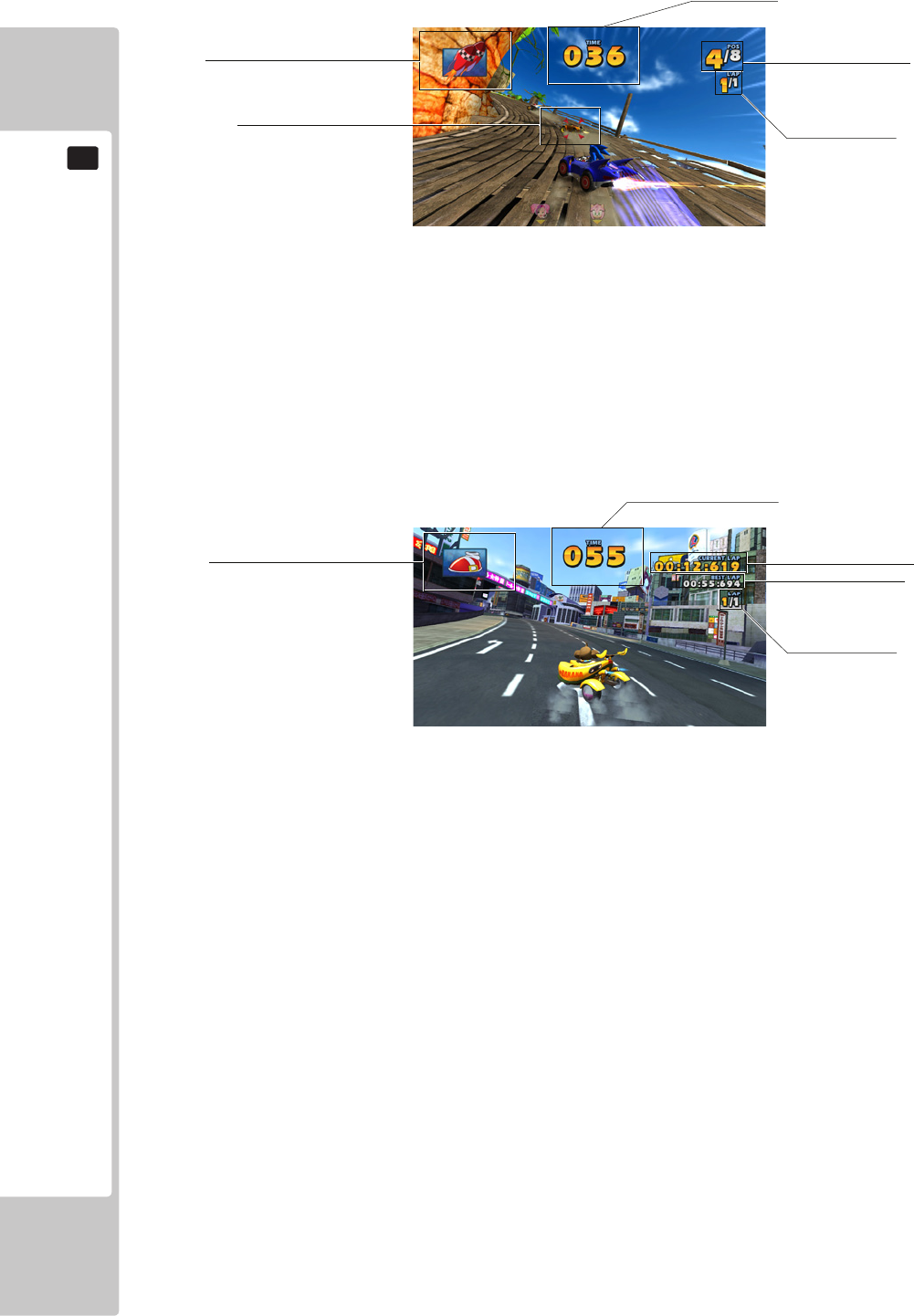
SINGLE RACE AND GRAND PRIX
Item Box – Displays the Item currently held by the player.
Time Left – Time remaining to complete the lap and extend the time.
Lap Indicator – Displays which lap the player is currently on.
Position – Displays the player’s position in the race.
Proximity Indicator – Represents position and distance of opponents approaching from the rear.
TIME TRIALS
Item Box – Displays the Item currently held by the player.
Time Left – Time remaining to complete the lap and extend the time.
Current Lap – Displays the time of the lap the player is currently on.
Best Lap – Displays the time of the best lap that has been achieved on the track.
Lap Indicator – Displays which lap the player is currently on.
ITEM BOX
TIME LEFT
CURRENT LAP
BEST LAP
LAP INDICATOR
ITEM BOX
TIME LEFT
POSITION
LAP INDICATOR
PROXIMITY INDICATOR
GAME DESCRIPTION
35
8
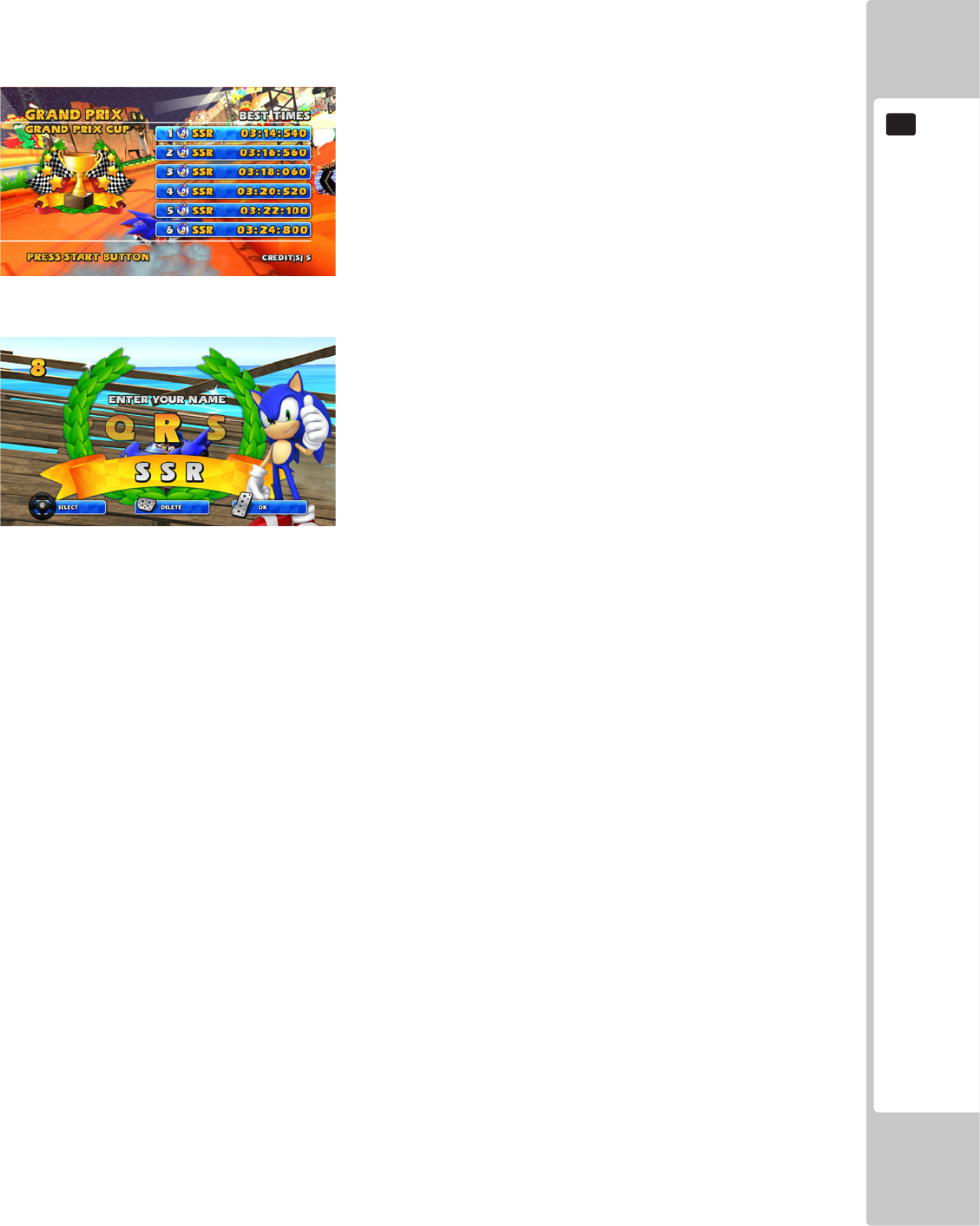
High Score Tables
Each of the single player modes except Single Race will record the fastest lap times with separate data being kept
for each track. In the case of Grand Prix it is not the fastest lap time, but the fastest total time in Grand Prix that is
recorded. Each of the High Score Tables will hold the Top 10 times for each track or Grand Prix.
Data Recorded:
Rank
Character Used
Name (3 characters)
Time
TO ENTER A NEW RECORD
1. Turn the Steering Wheel left and right to scroll to the required letter.
2. Press the Gas Pedal or Start Button to enter the letter.
3. Pressing the Brake Pedal will erase any selected letter.
36
EXPLANATION OF TEST AND DATA DISPLAY
9
9 EXPLANATION OF TEST AND DATA DISPLAY
Perform tests and data checks periodically by manipulating the TEST Button and SERVICE Button in the cabinet.
Follow the instructions in this chapter to conduct checks when the game machine is rst installed, when money is
being collected, or when the game machine does not operate properly.
Shown overleaf are the tests and screens to be used for different problems.
• When installing 2 of more cabinets which are networked together. The GAME
SETTINGS which are adjusted within the rst cabinet are reected throughout all
cabinets within that network.
• When changing the game conguration within the TEST MODE, be sure to exit
all screens in the correct manner by choosing exit. DO NOT turn the machine
ON/OFF to resume game. Changes WILL NOT take effect unless the correct
method is used.
EXPLANATION OF TEST AND DATA DISPLAY
37
9
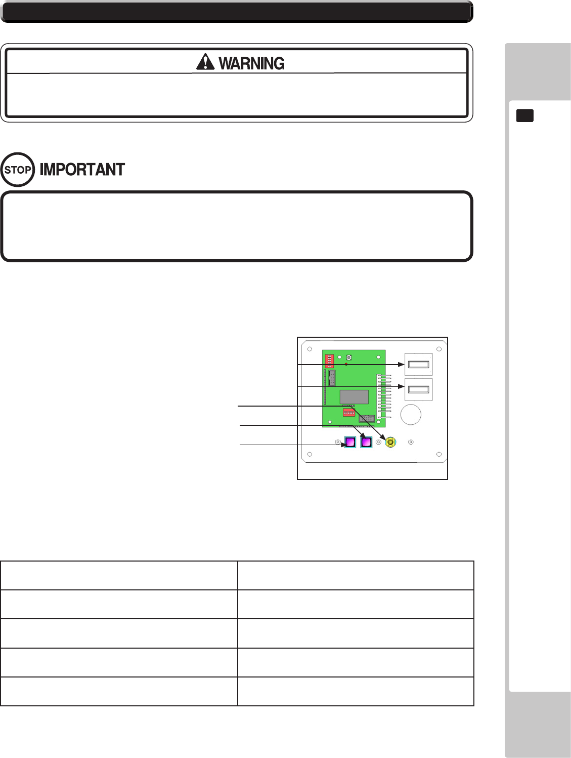
9-1-1 SWITCH UNIT
Open the coin chute door, and the switch unit shown will appear.
The functioning of each SW is as follows:
TEST Button (TEST): For the handling of the Test Button, refer to the
following pages.
SERVICE Button (SERVICE): Gives credits without registering on the coin meter.
Sound Volume Switch (SOUND VOLUME): Adjust sound volume for all of the machines’ speakers.
Coin Counter Counts and displayes coins in $0.10 units.
Game Counter Counts games played
• Adjust the sound to the optimum volume, taking into consideration the
environmental requirements of the installation location.
• Removing the Coin Meter circuitry renders the game inoperable.
9-1 SWITCH UNIT AND COIN METER.
Never touch places other than those specied. Touching places not specied can
cause electric shock and short circuit accidents.
9-1-1 FIG. 01
Volume Control
Service Button
Test Button
Game Counter (not used)
Coin Counter
38
EXPLANATION OF TEST AND DATA DISPLAY
9
9-2 SYSTEM TEST MODE
■ SYSTEM TEST MODE Screen
1 PresstheTESTButtonafterpoweringontheunittodisplaythefollowingSYSTEMTESTMODE.
2 Use the SERVICE Button to move the cursor to the desired test item.
3Press the TEST Button to enter the selected item’s test.
4After the test is complete, move the cursor to EXIT and press the TEST Button to return to the game
play screen.
Each item is explained below.
The details of changes to Test Mode settings are saved when you exit from each
Test Mode by selecting EXIT. Be careful because if the power is turned off before
that point, changes to the settings will be lost.
SYSTEMTESTMODEcanbeusedtochecktheinformationortheoperationofRINGWIDE,adjustMonitorcolor,
andperformcoin/creditsettings.
SYSTEM TEST MODE
GAME TEST MODE ...........................9-3
SYSTEM INFORMATION ....................9-4
STORAGE INFORMATION ................9-5
JVS TEST ............................................9-6
MONITOR TEST .................................9-7
SPEAKER TEST ...................................9-8
COIN ASSIGNMENTS .......................9-9
CLOCK SETTING ..............................9-10
NETWORK SETTING ......................... 9-11
-> EXIT ....................................................9-12
SELECT WITH SERVICE BUTTON
AND PRESS TEST BUTTON
EXPLANATION OF TEST AND DATA DISPLAY
39
9
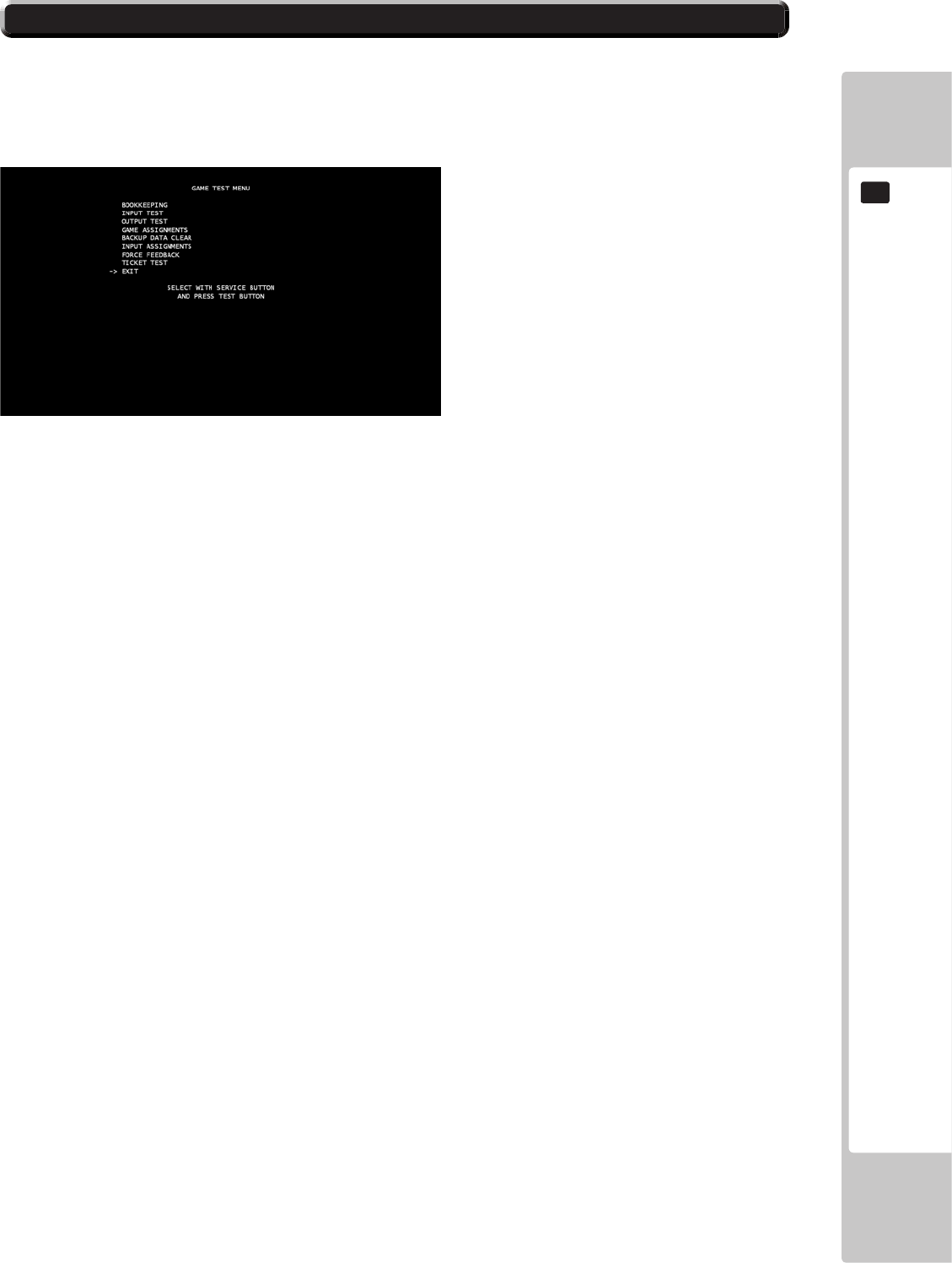
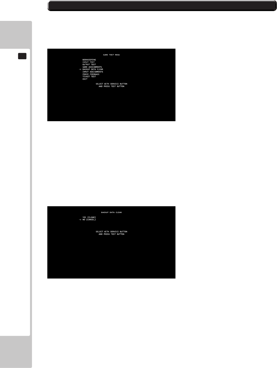
9-3 GAME TEST MODE
Opens the Game Test Mode, allowing game specic settings and tests to be performed. This option will be displayed in grey
until preparations are complete. Select the Game Test Mode option to begin the game test.
The following options are available from the Game Test Mode.
Use the SERVICE button to move the cursor to the desired test item.
Press the TEST button to enter the selected item.
BOOKKEEPING – System meters and bookkeeping.
INPUT TEST – Test routine for input peripherals
OUTPUT TEST – Test routine for out peripherals
GAME ASSIGNMENTS – Change settings within the game.
BACKUP DATA CLEAR – Clear the backup data within the game.
INPUT ASSIGNMENTS – Calibration routine for input peripherals
FORCE FEEDBACK – Change the force feedback settings within the game.
TICKET TEST – Test the ticket settings within the game.
EXIT – Press the Test button to return to the System Test Mode screen.
40
EXPLANATION OF TEST AND DATA DISPLAY
9
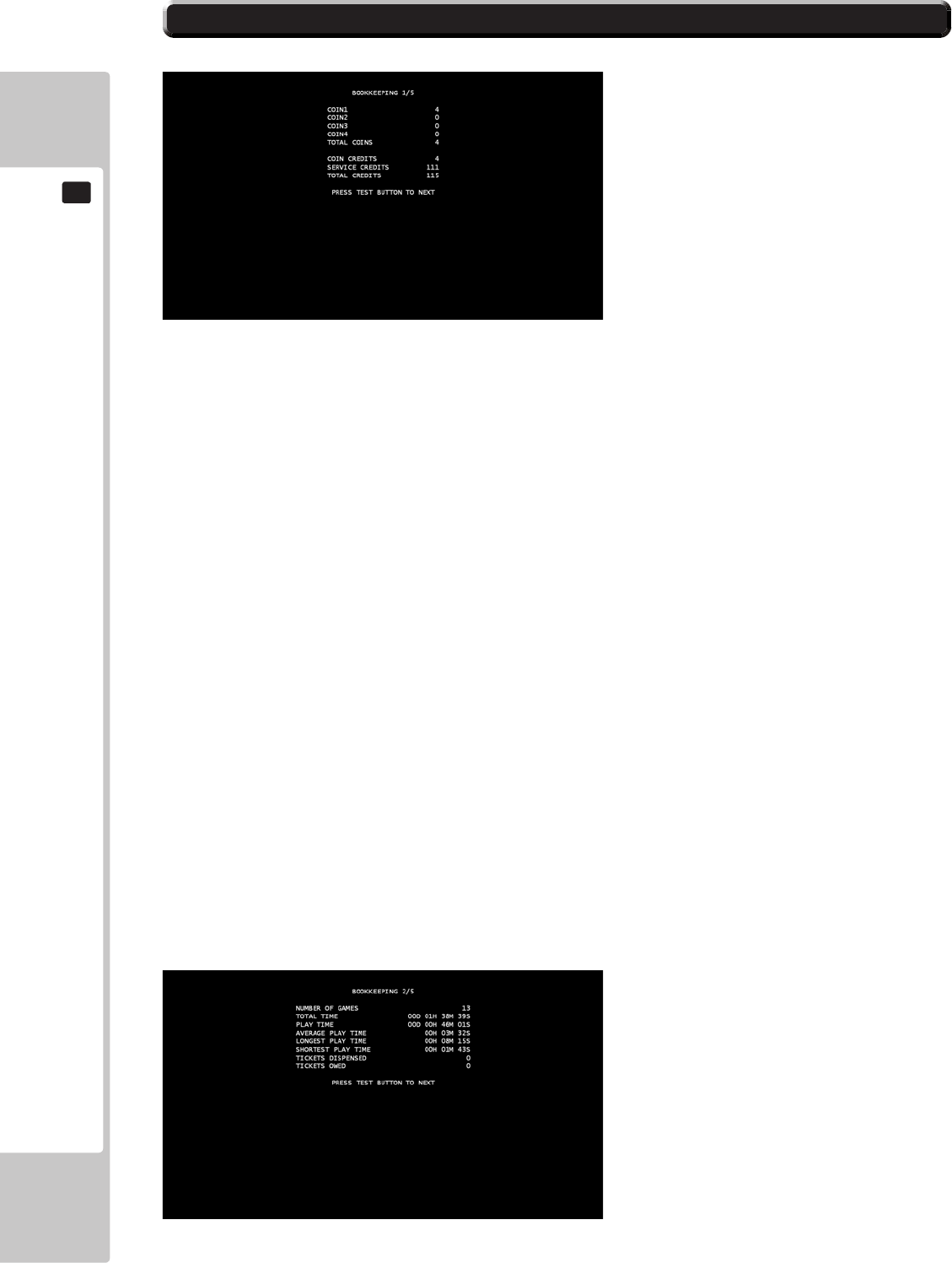
Select “Bookkeeping” from the Game Test Mode screen to enter the Bookkeeping screen.
Bookkeeping Page 1
This test is used to review statistical data from the system. It consists of 5 screens of data. Page 1 displays an overview
of the coins and credits data.
COIN 1 – Displays number of coins used for each cabinet when one coin mech is used and Coin Chute Type is set to
COMMON. This is for Cabinet 1.
COIN 2 – Displays number of coins used for each cabinet when one coin mech is used and Coin Chute Type is set to
COMMON. This is for Cabinet 2. (This is not applicable to Sonic & SEGA All Stars Racing Arcade).
COIN 3 – Displays number of coins used for each cabinet when one coin mech is used and Coin Chute Type is set to
COMMON. This is for Cabinet 3. (This is not applicable to Sonic & SEGA All Stars Racing Arcade).
COIN 4 – Displays number of coins used for each cabinet when one coin mech is used and Coin Chute Type is set to
COMMON. This is for Cabinet 4. (This is not applicable to Sonic & SEGA All Stars Racing Arcade).
TOTAL COINS – Displays the total number of coins used.
COIN CREDITS – Displays the number of credits used by inserting a coin.
SERVICE CREDITS – Displays the number of service credits used.
TOTAL CREDITS – Displays the total number of credits used between COIN and SERVICE
Press the Test Button to go to Page 2.
PAGE 2/5
9-3-1 BOOKKEEPING
EXPLANATION OF TEST AND DATA DISPLAY
41
9
Bookkeeping – Page 2 – Data on Average Game Times
NUMBER OF GAMES – Displays the total number of games played.
TOTAL TIME ON – Displays the total amount of time the cabinet has been on.
PLAY TIME – Displays the total amount of play time within the game.
AVERAGE PLAY TIME – Displays the average amount of time played during each session.
LONGEST PLAY TIME – Displays the longest amount of time played during one session.
SHORTEST PLAY TIME – Displays the shortest amount of time played during one session.
TICKETS DISPENSED – Displays the amount of tickets that have been dispensed.
TICKETS OWED – Displays the number of tickets that are owed.
Press the Test Button to go to Page 3.
PAGE 3/5
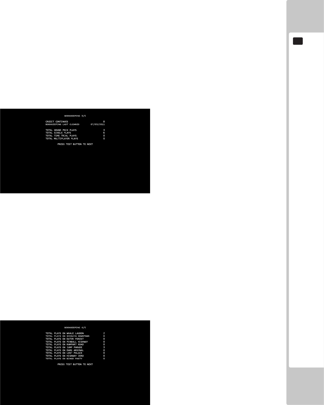
Bookkeeping – Page 3 – Data on Game Mode Plays
CREDIT CONTINUES – The number of coin credit continues used in Grand Prix
BOOKKEEPING LAST CLEARED – Displays the date of the last time the bookkeeping was cleared.
TOTAL GRAND PRIX PLAYS – Displays the total amount of times Grand Prix has been played.
TOTAL SINGLE PLAYS – Displays the total amount of times Single Race has been played.
TOTAL TIME TRIAL PLAYS – Displays the total amount of times Time Trials has been played.
TOTAL MULTIPLAYER PLAYS – Displays the total amount of times Multiplayer has been played.
Press the Test Button to go to Page 4.
PAGE 4/5

42
EXPLANATION OF TEST AND DATA DISPLAY
9
Bookkeeping – Page 4 – Data on Track Plays
TOTAL PLAYS ON WHALE LAGOON – The total amount of times Whale Lagoon has been played.
TOTAL PLAYS ON SHIBUYA DOWNTOWN – The total amount of times Shibuya Downtown has been played.
TOTAL PLAYS ON OUTER FOREST – The total amount of times Outer Forest has been played.
TOTAL PLAYS ON PINBALL HIGHWAY – The total amount of times Pinball Highway has been played.
TOTAL PLAYS ON RAMPART ROAD – The total amount of times Rampart Road has been played.
TOTAL PLAYS ON JUMP PARADE – The total amount of times Jump Parade has been played.
TOTAL PLAYS ON DARK ARSENAL – The total amount of times Dark Arsenal has been played.
TOTAL PLAYS ON LOST PALACE – The total amount of times Lost Palace has been played.
TOTAL PLAYS ON HIGHWAY ZERO – The total amount of times Highway Zero has been played.
TOTAL PLAYS ON BINGO PARTY – The total amount of times Bingo Party has been played.
Press the Test Button to go to Page 5.
PAGE 5/5
Bookkeeping – Page 5 – Data on Characters Used
TOTAL PLAYS WITH SONIC – The total amount of times Sonic has been used.
TOTAL PLAYS WITH AIAI – The total amount of times AiAi has been used.
TOTAL PLAYS WITH AMIGO – The total amount of times Amigo has been used.
TOTAL PLAYS WITH AMY – The total amount of times Amy has been used.
TOTAL PLAYS WITH BEAT – The total amount of times Beat has been used.
TOTAL PLAYS WITH B.D. JOE – The total amount of times B.D. Joe has been used.
TOTAL PLAYS WITH BILLY HATCHER – The total amount of times Billy Hatcher has been used.
TOTAL PLAYS WITH EGGMAN – The total amount of times Eggman has been used.
TOTAL PLAYS WITH RYO (BIKE) – The total amount of times Ryo (Bike) has been used.
TOTAL PLAYS WITH RYO (FORKLIFT) – The total amount of times Ryo (Forklift) has been used.
TOTAL PLAYS WITH SHADOW – The total amount of times Shadow has been used.
TOTAL PLAYS WITH TAILS – The total amount of times Tails has been used.
TOTAL PLAYS WITH ULALA – The total amount of times Ulala has been used.
TOTAL PLAYS WITH JACKIE – The total amount of times Jacky & Akira has been used.
Press the Test Button to return to the Game Test Mode screen.
EXPLANATION OF TEST AND DATA DISPLAY
43
9
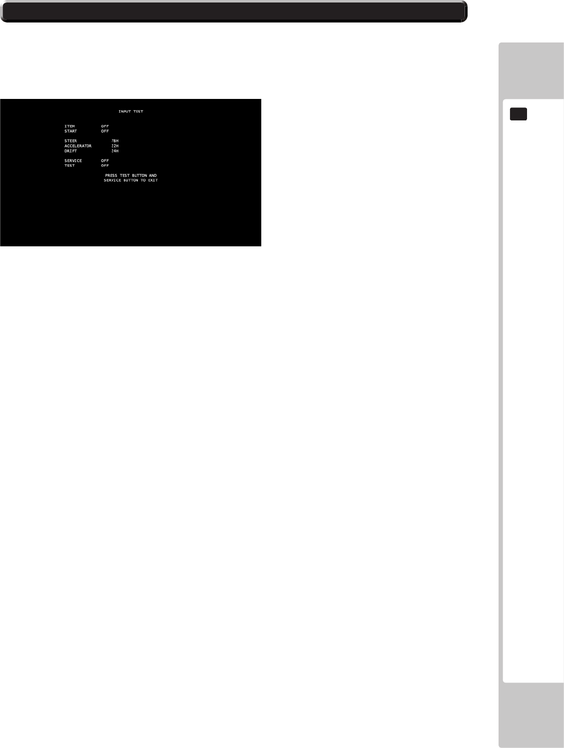
9-3-2 INPUT TEST
INPUT TEST
Select ‘Input Test’ from the Game Test Mode to display the Input Test menu.
This menu is used to test the System Inputs such as Steering, Pedals and Buttons. To implement the test, press each
device that is listed and check the results on screen.
ITEM – ON = Pressed, OFF = Not Pressed.
START – ON = Pressed, OFF = Not Pressed.
STEERING – 0000 = Fully Left; FFH = Fully Right (Numbers are approximate, may vary on cabinets).
ACCELERATOR – 0000 = Pedal Fully Up; FFH = Pedal Fully Down (Numbers are approximate, may vary on
cabinets).
DRIFT – 0000 = Pedal Fully Up; FFH = Pedal Fully Down (Numbers are approximate, may vary on cabinets).
SERVICE – ON = Pressed, OFF = Not Pressed.
TEST – ON = Pressed, OFF = Not Pressed.
Press the TEST and SERVICE button together to return to the Game Test Mode screen.
44
EXPLANATION OF TEST AND DATA DISPLAY
9
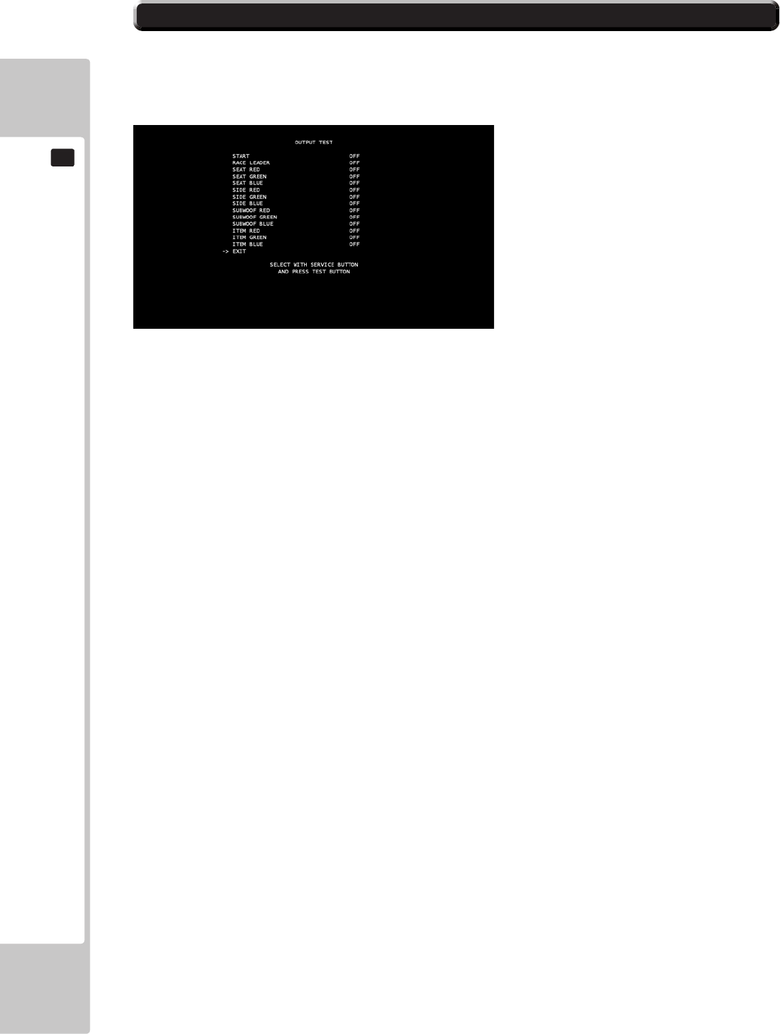
9-3-3 OUTPUT TEST
OUTPUT TEST
Select ‘Output Test’ from the Game Test Mode to display the Output Test Menu.
This test is used to check the System Output on the Lamps in the cabinet.
Use the SERVICE button to move the cursor to the desired test item.
Press the TEST button to test the selected item.
START – ON = Lamp ON, OFF = Lamp OFF.
RACE LEADER – ON = Lamp ON, OFF = Lamp OFF.
SEAT RED – ON = Lamp ON, OFF = Lamp OFF.
SEAT GREEN – ON = Lamp ON, OFF = Lamp OFF.
SEAT BLUE – ON = Lamp ON, OFF = Lamp OFF.
SIDE RED – ON = Lamp ON, OFF = Lamp OFF.
SIDE GREEN – ON = Lamp ON, OFF = Lamp OFF.
SIDE BLUE – ON = Lamp ON, OFF = Lamp OFF.
SUBWOOF/TICKET BOX RED – ON = Lamp ON, OFF = Lamp OFF.
SUBWOOF/TICKET BOX GREEN – ON = Lamp ON, OFF = Lamp OFF.
SUBWOOF/TICKET BOX BLUE – ON = Lamp ON, OFF = Lamp OFF.
ITEM RED – ON = Lamp ON, OFF = Lamp OFF.
ITEM GREEN – ON = Lamp ON, OFF = Lamp OFF.
ITEM BLUE – ON = Lamp ON, OFF = Lamp OFF.
EXIT – Press the Test button to return to the Game Test Mode screen.
EXPLANATION OF TEST AND DATA DISPLAY
45
9
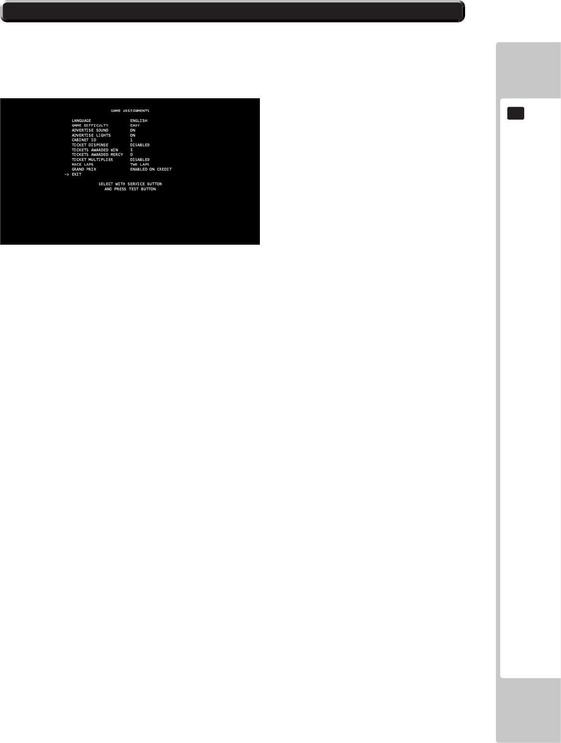
9-3-4 GAME ASSIGNMENTS
GAME ASSIGNMENTS
Select ‘Game Assignments’ from the Game Test Mode to display the Game Assignments Menu.
This test is used to change the game settings within the game.
Use the SERVICE button to move the cursor to the desired test item.
Press the TEST button to change the selected item.
LANGUAGE – Change the language that is used within the game itself. This can be switched between English,
French, German, Spanish, Russian and Turkish.
GAME DIFFICULTY – Change the difculty level of the game. It can be switched between EASY, NORMAL and
HARD.
ADVERTISE SOUND – Set whether music is displayed during the Attract Sequence. It can be switched between ON
and OFF.
ADVERTISE LIGHTS - Set between ON/OFF. When set to ON activates the CABINET LIGHTING FEATURE.
CABINET ID – Set the Cabinet ID.
TICKET DISPENSE – Set whether tickets are dispensed in the game. It can be switched between ENABLED and
DISABLED.
TICKETS AWARDED WIN – Set the amount of tickets that are dispensed when the player wins.
TICKETS AWARDED MERCY – Set the amount of tickets that are dispensed when the player loses.
TICKET MULTIPLIER - Set whether the tickets dispensed are multiplied for a multiplayer race. It can be switched
between ENABLED and DISABLED.
RACE LAPS – Set the number of laps that are used in a race. It can be switched between ONE, TWO or THREE laps.
GRAND PRIX – Set whether the Grand Prix game mode can be used in Single Player. It can be switched between
ENABLED and DISABLED.
EXIT – Press the Test Button to return to the Game Test Mode screen.
46
EXPLANATION OF TEST AND DATA DISPLAY
9
9-3-5 BACKUP DATA CLEAR
BACKUP DATA CLEAR
Select ‘Backup Data Clear’ from the Game Test Mode to display the Backup Data Clear Menu.
This test is used to clear the backup data.
Use the SERVICE button to move the cursor to the desired test item.
Use the TEST button to enter the selected item.
YES (CLEAR) – Clears the backup data. Once completed, press the Test Button to return to the Game Test Mode
screen.
NO (CANCEL) – Does not clear the backup data. Selecting this will return to the Game Test Mode screen.
EXPLANATION OF TEST AND DATA DISPLAY
47
9
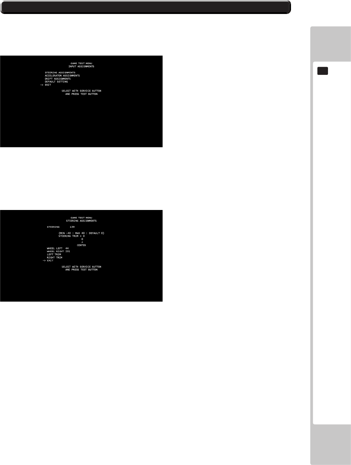
9-3-6 INPUT ASSIGNMENTS
STEERING ASSIGNMENTS
Press the Test Button when Steering is highlighted to enter the Steering Calibration menu.
Use the SERVICE button to move the cursor to the desired test item.
Press the TEST button to enter the selected item.
This screen can be used to check the current calibration of the steering wheel, and the wheel can also be manually
calibrated from here.
STEERING – Displays the number that indicates the centre of the wheel in the calibration settings.
WHEEL LEFT – Displays the current calibration setting for the steering wheel when it is full turned to the LEFT.
Press the Test Button to manually calibrate this setting, by turning the steering wheel fully to the LEFT and then
pressing the Test Button again to save this setting.
WHEEL RIGHT - Displays the current calibration setting for the steering wheel when it is full turned to the RIGHT.
Press the Test Button to manually calibrate this setting, by turning the steering wheel fully to the RIGHT and then
pressing the Test Button again to save this setting.
LEFT TRIM – Pressing the Test Button when this is highlighted will calibrate the wheel slightly to the LEFT with
each button press.
RIGHT TRIM – Pressing the Test Button when this is highlighted will calibrate the wheel slightly to the RIGHT with
each button press.
EXIT – Press the Test Button to return to the Input Assignments menu.

48
EXPLANATION OF TEST AND DATA DISPLAY
9
ACCELERATOR PEDAL ASSIGNMENTS
Press the Test Button when Accelerator Pedal is highlighted to enter the Accelerator Pedal Calibration menu.
Use the SERVICE button to move the cursor to the desired test item.
Press the TEST button to enter the selected item.
This screen can be used to check the current calibration of the accelerator pedal and to manually calibrate the pedal.
ACCELERATOR – Display the current placement of the Accelerator Pedal. Pressing the Accelerator down and
releasing the pedal will change this number.
PEDAL UP – Displays the current calibration setting for the Accelerator Pedal when it is not being pressed down.
Pressing the Test Button will allow for manual calibration, pressing the Test Button again will save this setting.
PEDAL DOWN – Displays the current calibration setting for the Accelerator Pedal when it is pressed fully down.
Pressing the Test Button will allow for manual calibration, pressing the Test Button again will save this setting.
EXIT – Press the Test Button to return to the Input Assignments menu.
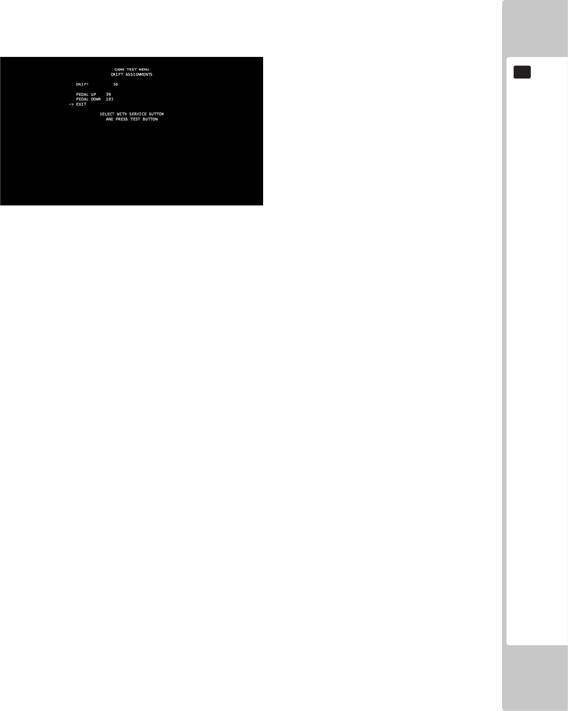
EXPLANATION OF TEST AND DATA DISPLAY
49
9
DRIFT PEDAL ASSIGNMENTS
Press the Test Button when Brake Pedal is highlighted to enter the Brake Pedal Calibration menu.
Use the SERVICE button to move the cursor to the desired test item.
Press the TEST button to enter the selected item.
This screen can be used to check the current calibration of the brake pedal and to manually calibrate the pedal.
DRIFT – Displays the current placement of the Brake Pedal. Pressing the Brake Pedal down and releasing the pedal
will change this number.
PEDAL UP – Displays the current calibration setting for the Brake Pedal when it is not being pressed down. Pressing
the Test Button will allow for manual calibration, pressing the Test Button again will save this setting.
PEDAL DOWN – Displays the current calibration setting for the Brake Pedal when it is pressed fully down. Pressing
the Test Button will allow for manual calibration, pressing the Test Button again will save this setting.
EXIT – Press the Test Button to return to the Input Assignments menu.
DEFAULT SETTING
Press the Test Button when this is highlighted to return all current calibration settings back to their default settings.
EXIT
Press the Test Button to return to the Game Test Menu.
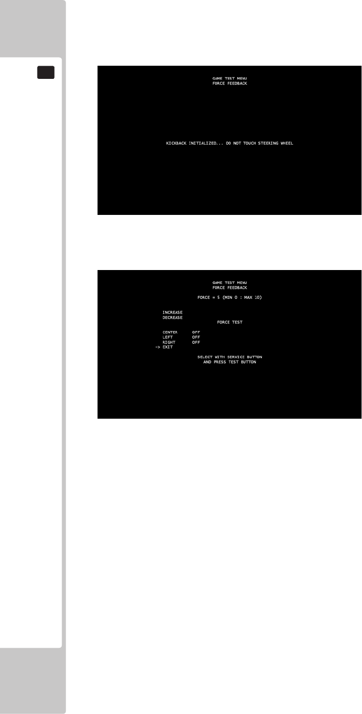
50
EXPLANATION OF TEST AND DATA DISPLAY
9
FORCE FEEDBACK
Select ‘Force Feedback’ from the Game Test Menu screen to display the Force Feedback menu.
This test is used to set the Force Feedback levels on the Steering Wheel. Upon initially entering the screen, the Steering
Wheel will automatically begin a kickback initialisation.
Use the SERVICE button to move the cursor to the desired test item.
Press the TEST button to enter the selected item.
INCREASE –Increases the current Force Feedback setting on the Steering Wheel. The values range from 0-10 in
strength with 0 being the weakest and 10 the strongest.
DECREASE – Decreases the current Force Feedback setting on the Steering Wheel. The values range from 0-10 in
strength with 0 being the weakest and 10 the strongest.
CENTER – ON = Rotates the Steering Wheel to the centre position. OFF = Stops the Steering Wheel rotating to this
position.
LEFT – ON = Rotates the Steering Wheel to the left position. OFF = Stops the Steering Wheel rotating to this position.
RIGHT – ON = Rotates the Steering Wheel to the right position. OFF = Stops the Steering Wheel rotating to this
position.
EXIT – Press the Test Button to return to the Game Test Menu.
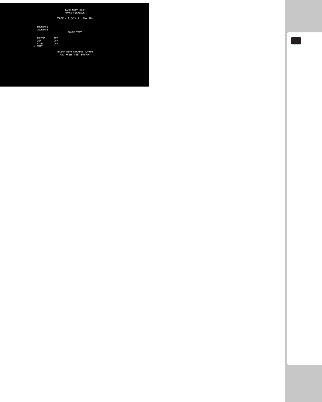
EXPLANATION OF TEST AND DATA DISPLAY
51
9
TICKET TEST
Select ‘Ticket Test’ from the Game Test Menu screen to display the Ticket Test menu.
This test is used to test the ticket dispenser unit, and to reimburse any tickets that are owed to players if the cabinet has
run out of tickets during gameplay.
Use the SERVICE button to move the cursor to the desired test item.
Press the TEST button to enter the selected item.
OPTO INPUT – Flashes ON briey whenever one ticket has been fully dispensed.
DETECT EMPTY – Switches to ON when the ticket dispensing machine has run out of tickets.
TICKET COUNT – States how many tickets have been dispensed in the game.
TICKETS OWED – States how many tickets are owed if the game ran out of tickets during gameplay.
MOTOR TEST – Tests the motor in the ticket dispense machine when switched to ON.
DISPENSE AMOUNT – States how many tickets will be dispensed when DISPENSE TEST is switched to ON. It can
be changed between 1, 5 and 10.
DISPENSE TEST – Dispenses the amount of tickets displayed in the DISPENSE AMOUNT when switched to ON.
RESET – Resets the Ticket Count.
EXIT – Press the Test Button to return to the Game Test Menu.
52
EXPLANATION OF TEST AND DATA DISPLAY
9
9-4 SYSTEM INFORMATION
● KEYCHIP
KEYCHIP ID The serial number of the key chip.
MODEL TYPE The model type.
REGION The region setting of the key chip.
● MOTHER BOARD
MAIN ID The serial number of the game board.
OS VERSION The system’s OS version.
REGION The region setting of the game board.
MEMORY SIZE The onboard memory size.
● STORAGE DEVICE
STORAGE SIZE The total capacity of the program installer device.
● GRAPHIC DEVICE
DEVICE ID The graphic device’s ID.
The SYSTEM INFORMATION screen displays system information.
The following information is displayed on this screen.
SYSTEM INFORMATION 1/2
The SYSTEM INFORMATION 1/2 screen displays system information.
The following information is displayed on this screen.
SYSTEM INFORMATION 1/2
KEYCHIP
KEYCHIP ID A72*-***********
MODEL TYPE *
REGION ***
MOTHER BOARD
MAIN ID ****-***********
OS VERSION *******
REGION **
MEMORY SIZE *****MB
STORAGE DEVICE
STORAGE SIZE *GB
GRAPHIC DEVICE
DEVICE ID ****:****
PRESS TEST BUTTON TO NEXT
PresstheTESTButtontomovetotheSYSTEMINFORMATION2/2.
■SYSTEMINFORMATION1/2Screen
EXPLANATION OF TEST AND DATA DISPLAY
53
9
The SYSTEM INFORMATION 2/2 screen displays system information.
Press the TEST Button on the SYSTEM INFORMATION 2/2 screen to return to the SYSTEM TEST MODE screen.
■SYSTEMINFORMATION2/2Screen
SYSTEM INFORMATION 2/2
The following information is displayed on this screen.
VOLTAGE CPU CORE CPU core voltage
VOLTAGE 3.3V 3.3 V voltage
VOLTAGE 5V 5 V voltage
VOLTAGE 12V 12 V voltage
VOLTAGE BATTERY Backup battery status
FAN CPU CPU fan RPM
FAN CHASSIS Case fan RPM
TEMP CPU CPU temperature
TEMP CHASSIS Case temperature
Press the TEST Button to return to the SYSTEM TEST MODE screen.
SYSTEM INFORMATION 2/2
VOLTAGE CPU CORE +*.**[V]
VOLTAGE 3.3V +*.**[V]
VOLTAGE 5V +**.**[V]
VOLTAGE 12V +*.**[V]
VOLTAGE BATTERY *****
FAN CPU ****[rpm]
FAN CHASSIS ****[rpm]
TEMP CPU **[C]
TEMP CHASSIS **[C]
PRESS TEST BUTTON TO EXIT
54
EXPLANATION OF TEST AND DATA DISPLAY
9
9-5 STORAGE INFORMATION
The STORAGE INFORMATION screen displays information on the game stored in the program installer device.
This screen is also used when uninstalling the game stored within the program installer device.
Until preparations to launch the game are complete, a now checking screen will be displayed and uninstall cannot be
performed.
If the program installer device does not contain any game data, “GAME PROGRAM NOT READY” screen will be displayed
and uninstall cannot be performed.
NOTE: If an uninstall is performed, an install will then have to performed before the game board can be used again. Do not
needless perform an uninstall.
(A)GAMETITLE
(B)INSTALLEDGAMEPROGRAMLIST
- GAME ID
- VERSION
- DATE & TIME OF RELEASE
(C) UNINSTALL
When preparations to launch the game are complete, it is possible to uninstall the game stored in the program
installer device. Select UNINSTALL and then select “YES” to uninstall all game programs stored in the
program installer device. Performing this operation will also mean that GAME TEST MODE will disappear from the
SYSTEM TEST MODE screen.
MovethecursortoEXITandpresstheTESTButtontoreturntotheSYSTEMTESTMODEscreen.
■ STORAGE INFORMATION Screen
Thefollowinginformationisdisplayedonthisscreen.
STORAGE INFORMATION
*********** ••••••••••••••••••••••• (A)
0: *** Ver.*.** ****/**/** **:**:** ••••••••••••••• (B)
1: *** Ver.*.** ****/**/** **:**:**
UNINSTALL •••••••••••••••••••••••••••••••••• (C)
-> EXIT
SELECT WITH SERVICE BUTTON
AND PRESS TEST BUTTON
EXPLANATION OF TEST AND DATA DISPLAY
55
9
9-6 JVS TEST
The JVS TEST screen displays information on the connected JVS I/O boards.
Select INPUT TEST to display input data for the currently displayed JVS I/O board.
Select NODE to display information on the next NODE.
If no JVS I/O boards are connected, the message “NO JVS NODE” will be displayed.
■ JVS TEST Screen
NOTE: The screen display will vary depending on the I/O board that is connected.
The gure above is one example.
JVS TEST
INPUT TEST
NODE 1/*
-> EXIT
NAME SEGA ENTERPRISES,LTD.:
I/O BD JVS :837-13551:
Ver1.00
CMD VER 1.1
JVS VER 2.0
COM VER 1.0
SWITCH 2 PLAYER(S) 13 BIT[S]
COIN 2 SLOT(S)
ANALOG 8 CH
ROTARY 0 CH
KEYCODE 0
SCREEN X:0 Y:0 CH:0
GENERAL IN 0 BIT(S)
CARD 0 SLOT(S)
HOPPER OUT 0 CH
DRIVER OUT 6 CH
ANALOG OUT 0 CH
CHARACTER CHARA:0 LINE:0
BACKUP 0
SELECT WITH SERVICE BUTTON
AND PRESS TEST BUTTON
56
EXPLANATION OF TEST AND DATA DISPLAY
9
The following information is displayed on this screen.
Move the cursor to EXIT and press the TEST Button to return to the SYSTEM TEST MODE screen.
NODE The currently displayed JVS I/O board number and the total number of connected
JVS I/O boards
NAME Name of the connected I/O board, etc.
CMD VER Command format version
JVS VER JVS standard version
COM VER Communication version
SWITCH Number of players and number of 1P switches
COIN Number of coin slots
ANALOG Number of analog channels
ROTARY Number of rotary encoders
KEYCODE Keycode input active/inactive
SCREEN Screen position input (X axis, Y axis, number of channels)
GENERAL IN Number of standard switches
CARD Number of card slots
HOPPER OUT Number of hoppers
DRIVER OUT Number of standard output drivers
ANALOG OUT Number of analog output channels
CHARACTER Number of characters/lines displayed
BACKUP Backup present/absent
EXPLANATION OF TEST AND DATA DISPLAY
57
9
Use the JVS INPUT TEST to test the JVS input.
The hexadecimal input information from the JVS I/O board will be displayed in real time.
■JVSINPUTTESTScreen
NOTE: The screen display will vary depending on the I/O board that is connected.
The gure above is one example.
JVS TEST
INPUT TEST
NODE 1/*
SYSTEM 00 ROTARY 0 0000
PLAYER 1 0000 ROTARY 1 0000
PLAYER 2 0000 ROTARY 2 0000
COIN 1 0000 ROTARY 3 0000
COIN 2 0000 ROTARY 4 0000
ANALOG 0 0000 ROTARY 5 0000
ANALOG 1 0000 ROTARY 6 0000
ANALOG 2 0000 ROTARY 7 0000
ANALOG 3 0000
ANALOG 4 0000
ANALOG 5 0000
ANALOG 6 0000
ANALOG 7 0000
PRESS TEST BUTTON AND
SERVICE BUTTON TO EXIT
JVS INPUT TEST
The following information is displayed on this screen.
Press the SERVICE and TEST Buttons simultaneously to return to the JVS TEST screen.
SYSTEM System switch input data
PLAYER Player number and player switch input data
COIN Slot number and coin input data
ANALOG Channel number and analog input data
ROTARY Rotary number and rotary input data
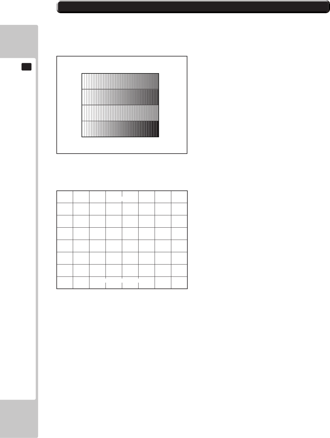
58
EXPLANATION OF TEST AND DATA DISPLAY
9
9-7 MONITOR TEST
Use MONITOR TEST to check the output of the monitor.
Enter MONITOR TEST and the MONITOR TEST 1/2 Screen will be displayed.
■ MONITOR TEST Screen 1/2
■MONITORTESTScreen2/2
Press TEST Button and the screen will change to the MONITOR TEST 2/2 Screen.
Press the TEST Button to return to the SYSTEM TEST MODE screen.
MONITOR TEST 1/2
PRESS TEST BUTTON TO NEXT
1
MONITOR TEST 2/2
PRESS TEST BUTTON TO EXIT

EXPLANATION OF TEST AND DATA DISPLAY
59
9
9-8 SPEAKER TEST
Use SPEAKER TEST to check the output of each speaker by having them each emit a test sound.
Select each speaker with the cursor and press the TEST Button to turn that speaker ON or OFF.
When set to ON a test sound will be emitted from that speaker.
It is possible to set multiple speakers to emit the test sound at the same time.
Depending on the cabinet used, some items will be displayed but no sound will be emitted.
SPEAKER TEST
LEFT SPEAKER OFF
RIGHT SPEAKER OFF
REAR LEFT SPEAKER OFF
REAR RIGHT SPEAKER OFF
CENTER SPEAKER OFF
WOOFER SPEAKER OFF
-> EXIT
SELECT WITH SERVICE BUTTON
AND PRESS TEST BUTTON
■SPEAKERTESTScreen
Move the cursor to EXIT and press the TEST Button to return to the SYSTEM TEST MODE screen.
60
EXPLANATION OF TEST AND DATA DISPLAY
9
9-9 COIN ASSIGNMENTS
Use COIN ASSIGNMENTS to alter the credit settings.
The game will award players the number of credits determined here.
Settings will only be saved if they have been changed.
■ COIN ASSIGNMENTS Screen
[COIN CHUTE TYPE: COMMON]
The following information is displayed on this screen.
(A) COIN CHUTE TYPE
COMMON Allow all credits to be used by all players.
INDIVIDUAL Treat each player’s credits individually.
(B) SERVICE TYPE (Service Button Type)
COMMON
When the COIN CHUTE TYPE is set to COMMON, the number of credits available to all
players will increase by 1.
When the COIN CHUTE TYPE is set to INDIVIDUAL, each player’s credits will increase by
1.
INDIVIDUAL
When the COIN CHUTE TYPE is set to COMMON, the number of credits available to all
players will increase by 1.
When the COIN CHUTE TYPE is set to INDIVIDUAL, the player corresponding to the
SERVICE Button’s credits will increase by 1.
COIN ASSIGNMENTS
COIN CHUTE TYPE COMMON ••••••••••••••••••••• (A)
SERVICE TYPE COMMON ••••••••••••••••••••• (B)
COIN CHUTE #1 COIN TO CREDIT RATE •••••••••••••• (C-1)
1 COIN(S) COUNT AS 1 CREDIT(S)
COIN CHUTE #2 COIN TO CREDIT RATE •••••••••••••• (C-2)
1 COIN(S) COUNT AS 1 CREDIT(S)
DETAIL SETTING ••••••••••••••••••••••••••••••••• (D)
GAME COST SETTING •••••••••••••••••••••••••••• (H)
-> EXIT •••••••••••••••••••••••••••••••••••••••••• (I)
SELECT WITH SERVICE BUTTON
AND PRESS TEST BUTTON
EXPLANATION OF TEST AND DATA DISPLAY
61
9
■ DETAIL SETTING Screen
(C-1) COIN CHUTE #1 COIN TO CREDIT RATE (Coin and credit conversion rate 1)
1 COIN(S) COUNT AS 1 CREDIT(S) 1 coin counts as 1 credit
2 COIN(S) COUNT AS 1 CREDIT(S) 2 coins count as 1 credit
3 COIN(S) COUNT AS 1 CREDIT(S) 3 coins count as 1 credit
4 COIN(S) COUNT AS 1 CREDIT(S) 4 coins count as 1 credit
5 COIN(S) COUNT AS 1 CREDIT(S) 5 coins count as 1 credit
1 COIN(S) COUNT AS 2 CREDIT(S) 1 coin counts as 2 credits
1 COIN(S) COUNT AS 3 CREDIT(S) 1 coin counts as 3 credits
1 COIN(S) COUNT AS 4 CREDIT(S) 1 coin counts as 4 credits
1 COIN(S) COUNT AS 5 CREDIT(S) 1 coin counts as 5 credits
FREE PLAY Free play (no coins required)
DETAIL SETTING More detailed settings
(C-2)COINCHUTE#2COINTOCREDITRATE(Coinandcreditconversionrate2)
When (A) COIN CHUTE TYPE is set to “COMMON,” the detail settings for this item are restricted to the
settings listed in (C-1).
(D) DETAIL SETTING
The COIN ASSIGNMENTS DETAIL SETTING screen allows more detailed settings that cannot be performed on (C)
the COIN TO CREDIT RATE screen to be performed.
[COINCHUTETYPE:COMMON]
COIN ASSIGNMENTS
DETAIL SETTING
COIN CHUTE #1 MULTIPLIER ••••••••••••••••••••••••• E-1
1 COIN COUNT AS 1 COIN (S)
COIN CHUTE #2 MULTIPLIER ••••••••••••••••••••••••• E-2
1 COIN COUNT AS 1 COIN (S)
BONUS ADDER NO BONUS ADDER •••••••••••••• F
COIN TO CREDIT 1 COIN (S) 1 CREDIT ••••••••••••••••• G
-> EXIT
COIN CHUTE #1 OPERATION
COIN 1 2 3 4 5 6 7 8 9
CREDIT 1 2 3 4 5 6 7 8 9
COIN CHUTE #2 OPERATION
COIN 1 2 3 4 5 6 7 8 9
CREDIT 1 2 3 4 5 6 7 8 9
SELECT WITH SERVICE BUTTON
AND PRESS TEST BUTTON
62
EXPLANATION OF TEST AND DATA DISPLAY
9
The following information is displayed on this screen.
(E-1)COINCHUTE#1MULTIPLIER
Coin conversion rate for #1. (How many coins 1 inserted coin counts for)
(E-2)COINCHUTE#2MULTIPLIER
Coin conversion rate for #2. (How many coins 1 inserted coin counts for)
NOTE: When (A) COIN CHUTE TYPE is set to “COMMON,” COIN CHUTE #1 and COIN CHUTE #2 can be set
separately.
(F) BONUS ADDER
Useofabonuscoin.
(G) COIN TO CREDIT
The number of coins to number of credits conversion rate.
Move the cursor to EXIT and press the TEST Button to return to the COIN ASSIGNMENTS screen.
NO BONUS ADDER No bonus coin given
2 COINS GIVE 1 EXTRA COIN 2 coins inserted successively award 1 bonus coin
3 COINS GIVE 1 EXTRA COIN 3 coins inserted successively award 1 bonus coin
4 COINS GIVE 1 EXTRA COIN 4 coins inserted successively award 1 bonus coin
5 COINS GIVE 1 EXTRA COIN 5 coins inserted successively award 1 bonus coin
6 COINS GIVE 1 EXTRA COIN 6 coins inserted successively award 1 bonus coin
7 COINS GIVE 1 EXTRA COIN 7 coins inserted successively award 1 bonus coin
8 COINS GIVE 1 EXTRA COIN 8 coins inserted successively award 1 bonus coin
9 COINS GIVE 1 EXTRA COIN 9 coins inserted successively award 1 bonus coin
EXPLANATION OF TEST AND DATA DISPLAY
63
9
■ GAME COST SETTING Screen
COIN ASSIGNMENTS
GAME COST SETTING
* credit (s) to start
* credit (s) to continue
-> EXIT
SELECT WITH SERVICE BUTTON
AND PRESS TEST BUTTON
(H)GAMECOSTSETTING
Use the COIN ASSIGNMENTS GAME COST SETTING screen to set the cost (number of required credits) that the
game program will use to determine if there are enough credits to play the game.
A total of 8 game costs can be dened. The game cost is dened by the BOOT ID, and when the second boot recognizes
the game, the game cost dened by the BOOT ID will be displayed.
If the game is not recognized, the default game cost will be displayed.
NOTE: The screen display will vary depending on the game that is installed. The gure above is one example.
Move the cursor to EXIT and press the TEST Button to return to the COIN ASSIGNMENTS screen.
(I) EXIT
Move the cursor to EXIT and press the TEST Button to return to the SYSTEM TEST MODE screen.
64
EXPLANATION OF TEST AND DATA DISPLAY
9
9-10 CLOCK SETTING
UseCLOCKSETTINGtosetthedateandtime.
UsetheSERVICEButtontomovethecursortothecategorythatyouwishtochangeandpresstheTESTButtonto
increasethatvalue.HoldingtheTESTButtondownwillmakethevaluecontinuouslyincrease.
(A) CLOCK
Displays the current time and date.
The time and date can be changed by selecting CLOCK.
Use the SERVICE Button to move the underline to the item you want to change and press the TEST Button to change the
value.
If you select EXIT and press the TEST Button after changing the setting, you will be asked whether you really want to
make the changes.
Select “YES” to change the value or “NO” to leave it as it is, and press the TEST Button.
Games connected to the network will adjust the time automatically.
Exercise caution as the game may become unplayable if the time is changed.
(B)TIMEZONE
Displays the time zone setting. If the machine is not available for ALL.Net, it is not displayed.
■ CLOCK SETTING Screen
[DAYLIGHT SAVING TIME (DST): DISABLE]
CLOCK SETTING
CLOCK
20**/ */ * (THU) 12:00:00 •••••••••••••••••••••••••• A
TIMEZONE UTC+09:00 •••••••••••• B
DAYLIGHT SAVING TIME(DST) DISABLE •••••••••••••• C
-> EXIT
SELECT WITH SERVICE BUTTON
AND PRESS TEST BUTTON
EXPLANATION OF TEST AND DATA DISPLAY
65
9
(C)DAYLIGHTSAVINGTIME(DST)
Displays the daylight saving time setting.
If set to ENABLE, you can specify when to start and end daylight saving time.
Move the cursor to EXIT and press the TEST Button to return to the SYSTEM TEST MODE screen.
[DAYLIGHT SAVING TIME (DST): ENABLE]
CLOCK SETTING
CLOCK
20**/ */ *(TUE) 12:00:00
TIMEZONE UTC+09:00
DAYLIGHT SAVING TIME(DST) •••••••••••••••••••••• ENABLE
DST START
MAR/2nd/SUN 02:00:00
DST END
NOV/1st/SUN 02:00:00
-> EXIT
SELECT WITH SERVICE BUTTON
AND PRESS TEST BUTTON
66
EXPLANATION OF TEST AND DATA DISPLAY
9
9-11 NETWORK SETTING
Use NETWORK SETTING to determine network settings or to test the network.
There is no need to alter these settings for a game that does not use a network.
■NETWORKSETTING(SettingMenu)Screen
MAIN NETWORK Performs a network setting.
NETWORK TEST Performs a network test.
Move the cursor to EXIT and press the TEST Button to return to the SYSTEM TEST MODE screen.
The following information is displayed on this screen.
NETWORK SETTING
MAIN NETWORK
NETWORK TEST
-> EXIT
SELECT WITH SERVICE BUTTON
AND PRESS TEST BUTTON
When using a hub for connecting a number of cabinets in a network, please
change the IP addresses accordingly.
IP (192.168.88.XX) XX indicating the cabinet number. i.e. 192.168.88.01 for
cabinet 1. 192.168.88.02 for cabinet 2 and so on up to a
total of 8 cabinets.
• Do not connect any other device into the same hub as the linked cabinet.
Doing so will cause networking problems between cabinets
EXPLANATION OF TEST AND DATA DISPLAY
67
9
■NETWORKSETTING(NetworkSetting)Screen
MAIN NETWORK
Select MAIN NETWORK on the NETWORK SETTING (Setting Menu) and the following screen will be displayed.
The following information is displayed on this screen.
(A)MACADDRESS
The individual ID number assigned to each device using the Ethernet.
(B) DHCP
Set automatic acquisition of network settings.
ENABLE: Acquire network settings automatically. (use when connected to a router)
DISABLE: Input network settings manually. (use when connected to a Hub and/or xed IP address)
(C) IP ADDRESS
A setting required for the network.
After setting the numbers, select SET and press the TEST Button to save the setting.
When DHCP is set to ENABLE, this item cannot be selected.
(D)SUBNETMASK
A setting required for the network.
After setting the numbers, select SET and press the TEST Button to save the setting.
When DHCP is set to ENABLE, this item cannot be selected.
(E) GATEWAY
A setting required for the network. See the manual supplied with each game software for the correct setting.
After setting the numbers, select SET and press the TEST Button to save the setting.
When DHCP is set to ENABLE, this item cannot be selected.
(F)PRIMARYDNS
A setting required for the network. See the manual supplied with each game software for the correct setting.
After setting the numbers, select SET and press the TEST Button to save the setting.
When DHCP is set to ENABLE, this item cannot be selected.
(G) SECONDARY DNS
A setting required for the network. See the manual supplied with each game software for the correct setting.
After setting the numbers, select SET and press the TEST Button to save the setting.
When DHCP is set to ENABLE, this item cannot be selected.
Move the cursor to EXIT and press the TEST Button to return to the NETWORK SETTING (Setting Menu) screen.
NETWORK SETTING
MAC ADDRESS **-**-**-**-**-** ••••••••••••••••••• A
DHCP ******** •••••••••••••••••••••••• B
IP ADDRESS ••••••••••••••••••••••••••••••••••• C
***.***.***.***
SUBNET MASK ••••••••••••••••••••••••••••••••• D
***.***.***.***
GATEWAY •••••••••••••••••••••••••••••••••••• E
***.***.***.***
PRIMARY DNS ••••••••••••••••••••••••••••••••• F
***.***.***.***
SECONDARY DNS •••••••••••••••••••••••••••••• G
***.***.***.***
-> EXIT
SELECT WITH SERVICE BUTTON
AND PRESS TEST BUTTON
68
EXPLANATION OF TEST AND DATA DISPLAY
9
■NETWORKTESTScreen
DHCP Status of communication settings acquisition when DHCP is set to ENABLE.
LOOPBACK RINGWIDE network function operation status.
LINKUP LAN cable connection status.
GATEWAY Status of connection with title router, etc.
ROUTER Status of connection with ALL.Net router.
HOPS Number of router connections to ALL.Net router.
SERVER Status of connection with ALL.Net server.
NETWORK TEST
Check the network connection.
The test will begin as soon as this screen is displayed. The machine cannot be operated until the test is nished.
The status of determining items is as listed in the table below:
CHECK Indicates that the item is currently being checked.
GOOD Indicates that the item is functioning normally.
BAD Indicates that the item is not functioning normally.
(Damaged, incorrect settings, etc.)
N/A Indicates that the item has not been checked.
(Prerequisites have not been met, etc.)
Press the TEST Button to return to the NETWORK SETTING (Setting Menu) screen.
The following information is displayed on this screen.
9-12 EXIT
Exit the Test Mode.
NETWORK TEST
DHCP ------------ ****
LOOPBACK -------- ****
LINKUP ---------- ****
GATEWAY --------- ****
ROUTER ---------- ****
HOPS *
SERVER ---------- ****
PRESS TEST BUTTON TO EXIT
CONTROL UNIT
69
10
• When working with the product, be sure to turn the power off. Working with the
power on may cause an electric shock or short circuit.
• Be careful not to damage the wires. Damaged wires may cause an electric
shock, short circuit or present a risk of re.
• Exercise due caution in performing soldering work. If soldering iron is handled
carelessly, there could be res or burns.
• When fastening plastic parts, be careful not to tighten screws or nuts excessively.
If these are tightened to excess, parts could be damaged, resulting in injuries
from fragments, etc.
• After the unit has been disassembled and reassembled again, check carefully
that the unit has been reassembled correctly.
• Be sure to inspect the outer covers on both gear and hand brake units.
• Assemble so that there is no gap between the L and R covers. If there is a gap
or rattling, the players could get ngers or hands caught, resulting in injury.
• Once the product has been disassembled, use slack preventive agent (product
No. : 090-0012-N). Coat screws with suitable amounts of this agent and then
tighten them. If this agent is not used, the product might start rattling or come
apart.
• Use the slack preventive agent prescribed in these instructions. If any other
agent is used, there could be chemical changes that inhibit the use of screws
and part surfaces could be damaged.
• Be careful not to damage or lose small parts or screws.
• When a part has been replaced, be sure to always make adjustments and
check conditions in Test Mode.
10 CONTROLLER UNIT(S)
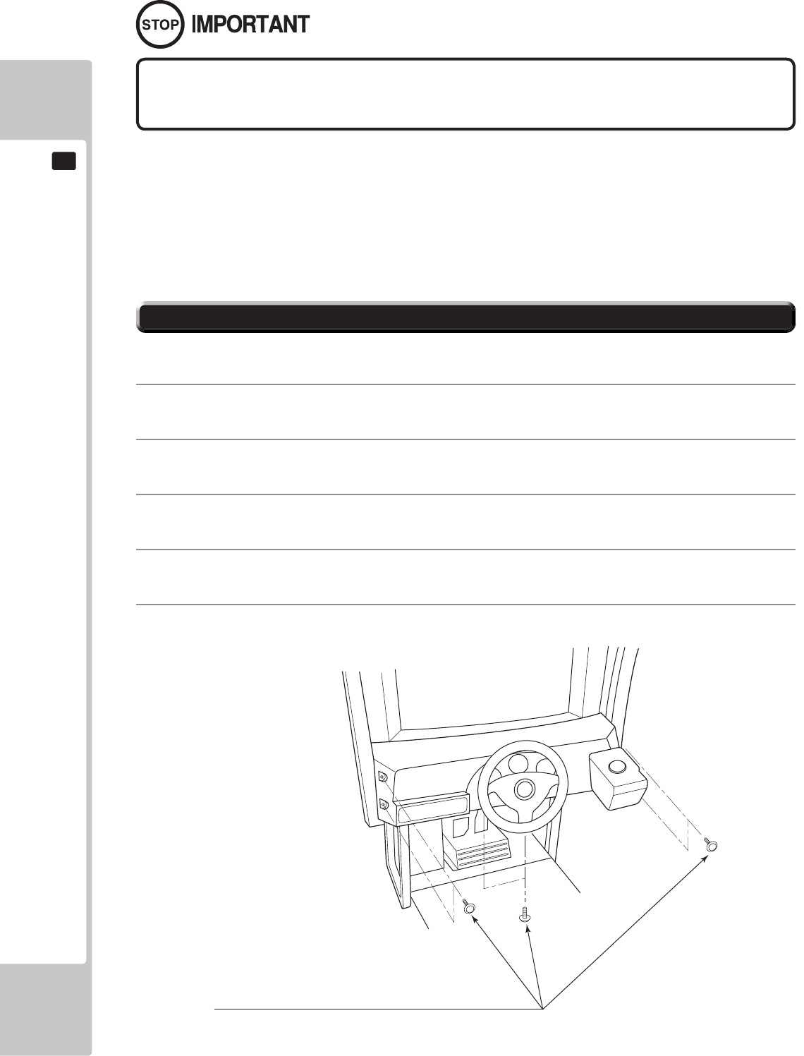
70
CONTROL UNIT
10
10-1 REMOVING THE CONTROL PANEL
Be sure to perform volume's move value setting in the INPUT ASSIGNMENTS in the
Game Test Mode after replacing or adjusting the Volume.
In cases the Steering operability is poor and the adjustment of VOLUME SETTING in the TEST mode has no effect,
the causes may be the volume gear's mesh failure and or volume malfunctioning.
Adjust volume gear mesh or replace the volume as per the following procedure.
In this product, when the steering wheel is moved fully left/right, if the volume shaft is rotating within the movable
range, the volume is not feared to be damaged.
Secure the volume in the manner the volume shaft is oriented as shown and the gears are appropriately engaged
when the steering wheel is in the centering position allowing the car to go straight forward.
A 5 mm hexagonal wrench is required for the following procedure.
1
Turn off the power.
2
Remove the 4 hexagon socket button head screws from both sides of the Control Panel’s front part.
3
Remove the 2 hexagon socket button head screws from underside of the Control Panel.
4
Wiring connectors are connected inside the Control Panel. Be careful not to damage any of the wiring, and
carefully pull out the Control Panel.
5
Unplug the wiring connectors.
HEXAGON SOCKET BUTTON HEAD SCREW (total 6), black
M8x30, flat and spring washers used
10-1 FIG. 01
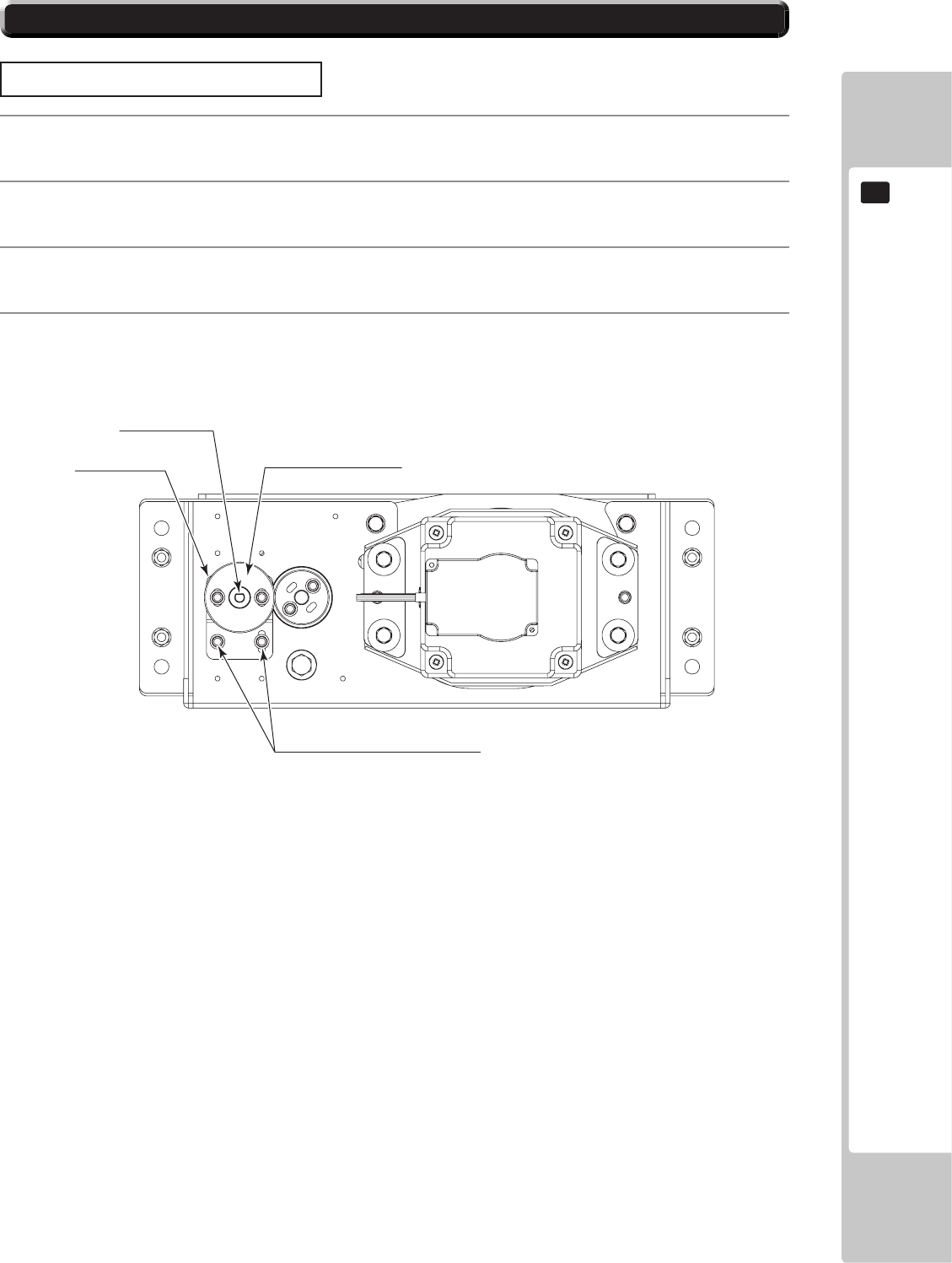
CONTROL UNIT
71
10
10-2 ADJUSTING/REPLACING THE VOLUME
ADJUSTMENT PROCEDURE
1
Loosen the 2 screws that secure the VR Bracket and move the VR Bracket to adjust the angle and condition
of the gear alignment.
2
Keeping the handle straight, align the gears so that the direction of the D Cut side of the V.R. Shaft matches
that shown in the diagram.
3
Tighten the 2 screws and secure the VR Bracket.
4
Check to make sure the value on the Input Test screen is within the range 80H ± 8H when the steering unit
is in the straight position.
“D” CUT SIDE
VR BRACKET
SCREW (2)
M4x8, w/flat & spring washers
VOLUME
220-5753, 220-5484
10-2 FIG. 01
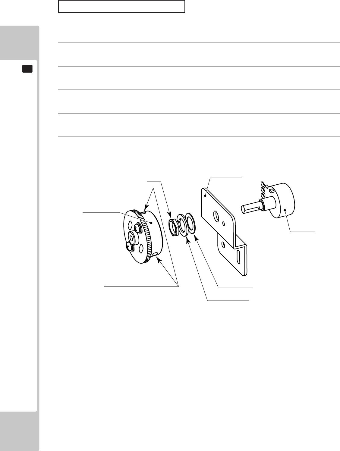
72
CONTROL UNIT
10
REPLACEMENT PROCEDURE
This procedure requires the following tools: Phillips screwdriver for the M4 screws, 1.5 mm hexagonal wrench,
11-12 mm monkey wrench, nipper, cutter, wire stripper, soldering iron, industrial dryer and heat-shrinkable tube.
1
Remove the connectors.
2
Remove the 2 screws securing the VR Bracket and remove the entire Bracket and V.R.
3
Loosen the 2 hexagon socket screws on the Gear Holder and remove the Gear Holder.
4
Remove the nut securing the VR Bracket, then separate the Volume from the VR Bracket and replace it.
5
Check to make sure the value on the Input Test screen is within the range 80H ± 8H when the steering unit
is in the straight position.
GEAR HOLDER
NUT VR BRACKET
FLAT WASHER
SPRING WASHER
HEXAGON SOCKET SCREW
M3x8
VOLUME
220-5484
220-5753
10-2 FIG. 02
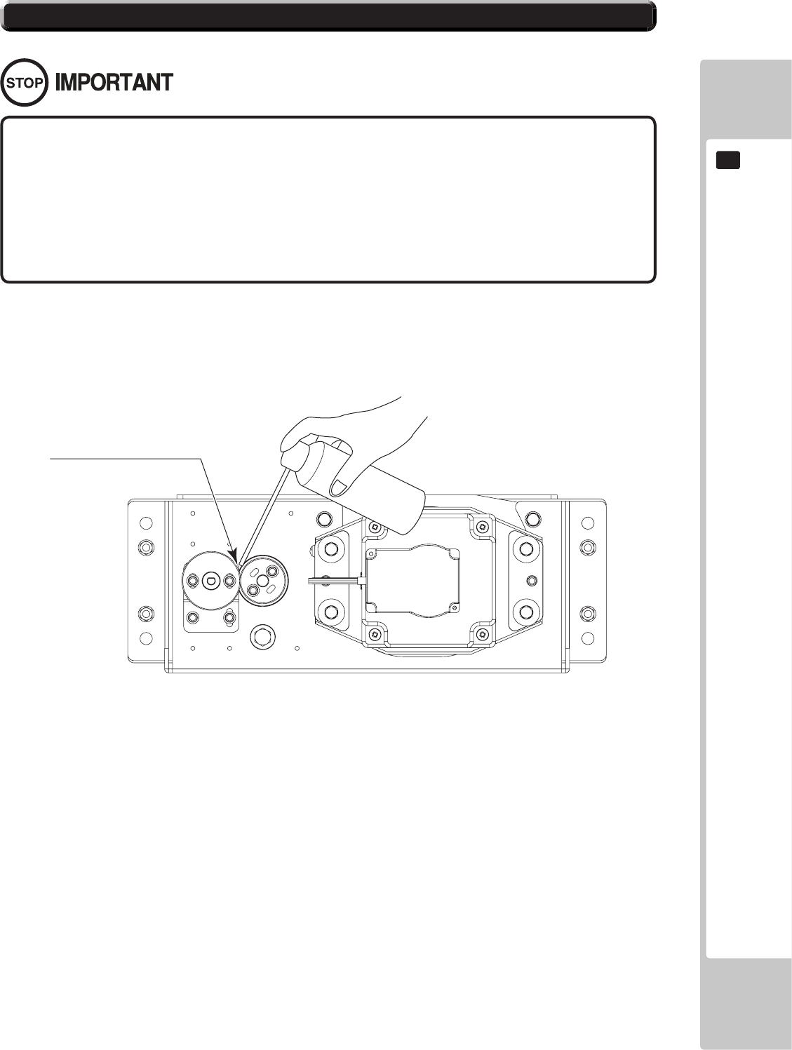
CONTROL UNIT
73
10
• Be sure to use the designated grease. Using undesignated grease can cause
parts damage.
• Do not apply grease to locations other than as specied. Doing so may create
a risk of operational problems and deterioration of parts.
• The designated periods for greasing serve only as a guide. Whenever there are
squeaks or other anomalies, apply grease at designated locations.
Use spray grease once every three months to grease up the gear mesh portion of the constituent parts.
Use "Grease Mate" (part number 090-0066) for the spray grease.
V.R. GEAR MESH PORTION
10-3 FIG. 01
10-3 GREASING
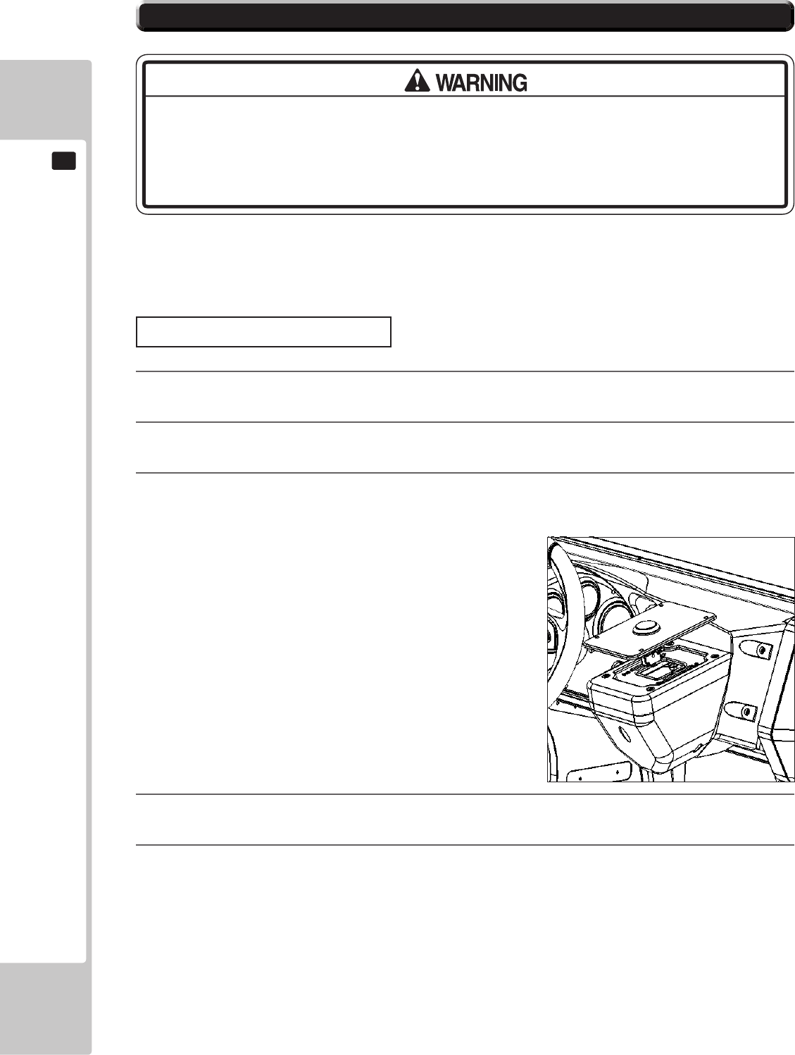
74
CONTROL UNIT
10
If the start switch input does not function correctly on the INPUT TEST screen, the switch may need to be replaced.
To carry out this maintenance, you must rst remove the start button unit.
For this task, you will need a tamper proof wrench (for M4 screws),
● When working with the product, be sure to turn the power off. Working with the
power on may cause an electric shock or short circuit.
● Be careful not to damage the wires. Damaged wires may cause an electric
shock, short circuit or present a risk of re.
1
Turn the power OFF
2
Using the M4 tamper proof wrench remove the four tamper proof screws, 1 located in each of the corner of
the Start Button Plate.
3
Gently lift out the Button Plate to reveal the wiring harness, locate the plug connecting it to the Control panel
and remove the connection. The Button and Plate can now be extracted.
4
When re-installing the Start Button and Plate follow the above instructions in the reverse order. At this time
ensure that the orientation of the Button Plate is correct before securing.
5
After the Re-installation of the Button Plate and Start Button, be sure to check the INPUT TEST in the Game
Test mode to determine it’s correct operation.
10-4 START BUTTON ASSY
Start Button Plate Removal
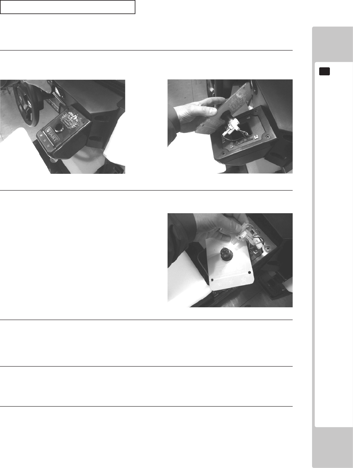
CONTROL UNIT
75
10
Follow the instructions below to change the microswitch.
1
Unscrew and remove the START BUTTON PLATE as explained on the previous page.
2
Remove the microswitch by unclipping it from the Lamp Housing
3
Remove the wiring harness from the old microswitch and re-attach it to the replacement switch in the same
manner
4
Clip the Microswich back into the lamp house making sure that it is fully in place.
5
The unit is now ready to be retted into the Control Panel, to do this follow the instructions in reverse order
Strart Button/switch replacement
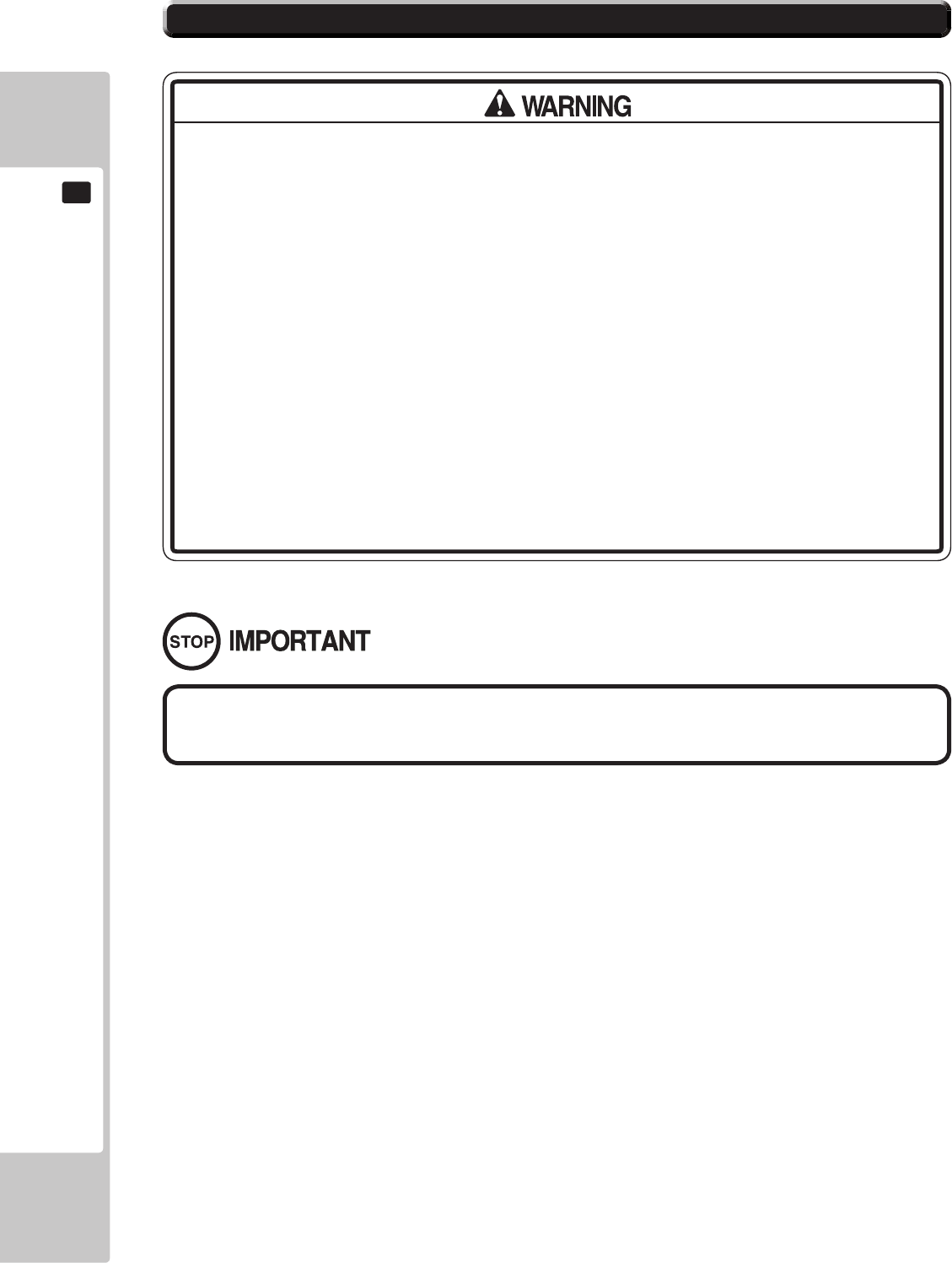
76
CONTROL UNIT
10
If the accelerator or brake pedals are not functioning correctly, you may need to adjust the positioning of the volume
or replace it with a new one. In addition, you should apply grease to the gear contacts and spring parts once every
three months.
When working with the product, be sure to turn the power off. Working with the
power on may cause an electric shock or short circuit. However, the unit must be
switched on when using test mode. Do not touch any part of the unit except those
areas indicated.
Be careful not to damage the wires. Damaged wires may cause an electric shock,
short circuit or present a risk of re.
This work should be performed by site maintenance personnel or other skilled
professionals. Work performed by non-technical personnel can cause a severe
accident such as an electric shock.
To prevent accidents while working or while operating the product after it has
been installed, be sure not to conduct any procedures other than those given
in this manual. There are cases in which procedures not covered in this manual
require special tools and skills.
If a procedure not given in this manual is required, request service from the ofce
given in this manual or from the point of purchase.
Be sure to perform volume's move value setting in the Input Test in the Game
Test Mode after replacing or adjusting the Volume.
10-5 BRAKE AND ACCELERATOR UNIT
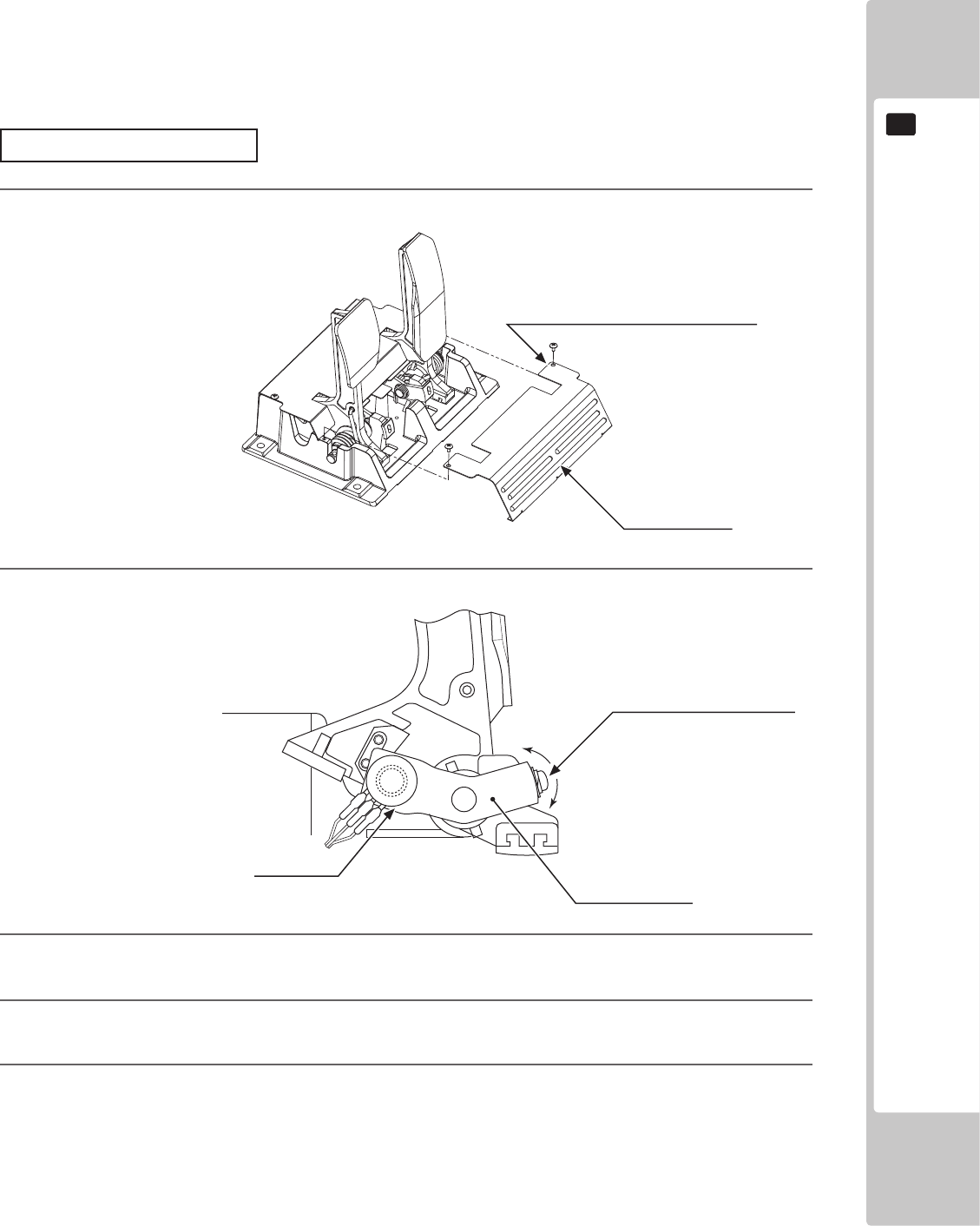
CONTROL UNIT
77
10
When the accelerator pedal is not being pressed, the accelerator volume should have a value of 30H or less. When
the pedal is being pressed, the value should be C0H or greater.
When the brake pedal is not being pressed, the value should be 35H or less. When the pedal is being pressed, it
should be D0H or more. You can view these values in test mode. Note that the unit must be switched on to use test
mode. Do not touch any part of the unit except those areas indicated when the unit is switch on, as there is a danger
of electrical shock or short-circuit.
For this task, you will need a Phillips-head screwdriver (for M4, M5 screws).
Adjusting Procedure
1
On the accelerator and brake pedal unit, remove the two truss screws and lift o the front cover.
10-3 FIG. 01
2
Loosen the single screw that secures the potentiobase, and move the base to adjust the volume
values.
10-3 FIG. 02
3
Secure the potentiobase.
4
Congure the volume values on the INPUT ASSIGNMENTS screen in Game Test Mode.
5
Check that the values change smoothly in response to pedal input.
TRUSS SCREW (2), chrome
M4x8
FRONT COVER
SCREW (1)
M5x12, w/at & spring washers
POTENTIOBASE
VOLUME
220-5484
220-5753
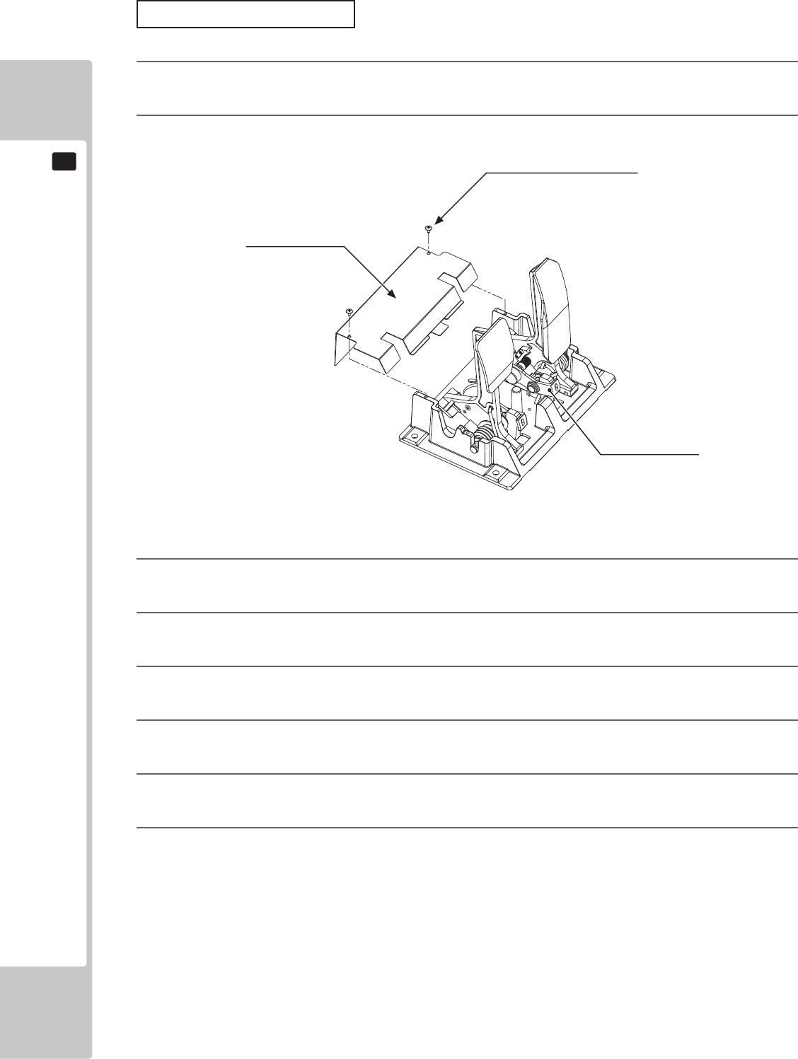
78
CONTROL UNIT
10
Replacing the Volume
1
Switch o the unit.
2
Remove the two screws and lift o the potentio cover.
10-3-1 FIG. 01
3
Detach the connector from the volume to be replaced.
4
Remove the single screw that secures the potentiobase. (see 10-31 FIG. 02).
5
Without detaching the volume, remove the potentiobase. (see 10-31 FIG. 03).
6
Remove the base and gear from the volume, and replace it.
7
After replacement, congure the volume as described above in “Adjusting Procedure”
8
When you have nished, check that the values change smoothly in response to pedal input.
TRUSS SCREW (2), chrome
M4x8
POTENTIO COVER
POTENTIOBASE
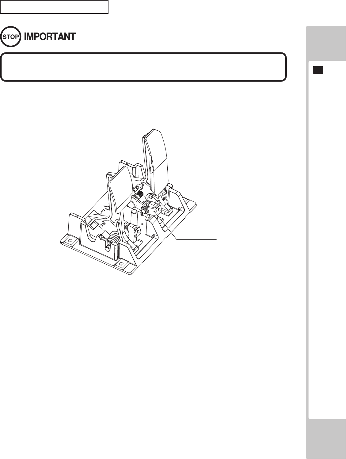
CONTROL UNIT
79
10
Once every three months, you should apply grease to the gear contacts and spring parts.
Use Grease Mate-brand spray grease (Part No.: 090-0066).
10-3-2 FIG. 01
Use only the specied grease. Using any other kind of grease can result in
damage to parts.
POTENTIOBASE
Adjusting the Volume Pot
80
GRAPHICS DISPLAY
11
Responding to breakdown or abnormality
● If smoke or a strange odor appears, immediately unplug the power cable from
the power source.
Continuing to use the product may cause a re or an electric shock. Ensure
that smoke is no longer emitted, and contact the point of purchase.
● If nothing displays on the screen, immediately unplug the power cable from
the power source.
Continuing to use the product may cause a re or an electric shock. Contact
the point of purchase and request an inspection.
● If water or a foreign object enters the monitor’s interior, immediately unplug the
power cable from the power source.
Continuing to use the product may cause a re or an electric shock. Contact
the point of purchase and request an inspection.
● If the monitor is dropped or the cabinet is damaged, immediately unplug the
power cable from the power source.
Continuing to use the product may cause a re or an electric shock. Contact
the point of purchase and request an inspection.
During operation
● Do not repair, reconstruct, or disassemble the monitor.
The monitors interior contains high voltage parts. A re or an electric shock
could result.
For inspections, adjustments, and repair of the monitors interior, request work
from the point of purchase.
● Do not insert foreign objects.
If metal objects or ammable materials such as paper are inserted into the
interior through ventilation openings or other apertures, an electric shock could
result.
● In the event of a thunder storm, do not touch the product or the power cable.
An electric shock could result.
● Make sure to perform appropriate adjustments. Do not operate
the product when the screen is ickering, distorted, or experiencing other
abnormalities. Images from an improperly adjusted screen could cause
players and other customers to experience dizziness, headaches, and other
ailments.
11-1 SAFETY PRECAUTIONS WHEN HANDLING THE MONITOR
11 GRAPHICS DISPLAY
GRAPHICS DISPLAY
81
11
CLEAN THE SCREEN DAILY.
11-2 CLEANING THE SCREEN SURFACE
● Use a soft, dry cloth (annel-type) to wipe away dirt. Do not use materials such
as coarse mesh gauze.
● Alcohol (ethanol) is the recommended solvent for removing dirt. When using a
cleaning agent, follow the precautions below.
- Dilute neutral cleaning agents for home use with water. Soak a soft cloth in the
solution, and wring it thoroughly before wiping the screen.
- Do not use abrasive cleaning agents or powders, or cleaning agents
containing bleach.
- Do not use alkaline cleaning agents such as glass cleaners, or solvents such as
thinners.
● Do not scrub or scratch the screen surface with abrasive materials such as
brushes or scrub brushes.
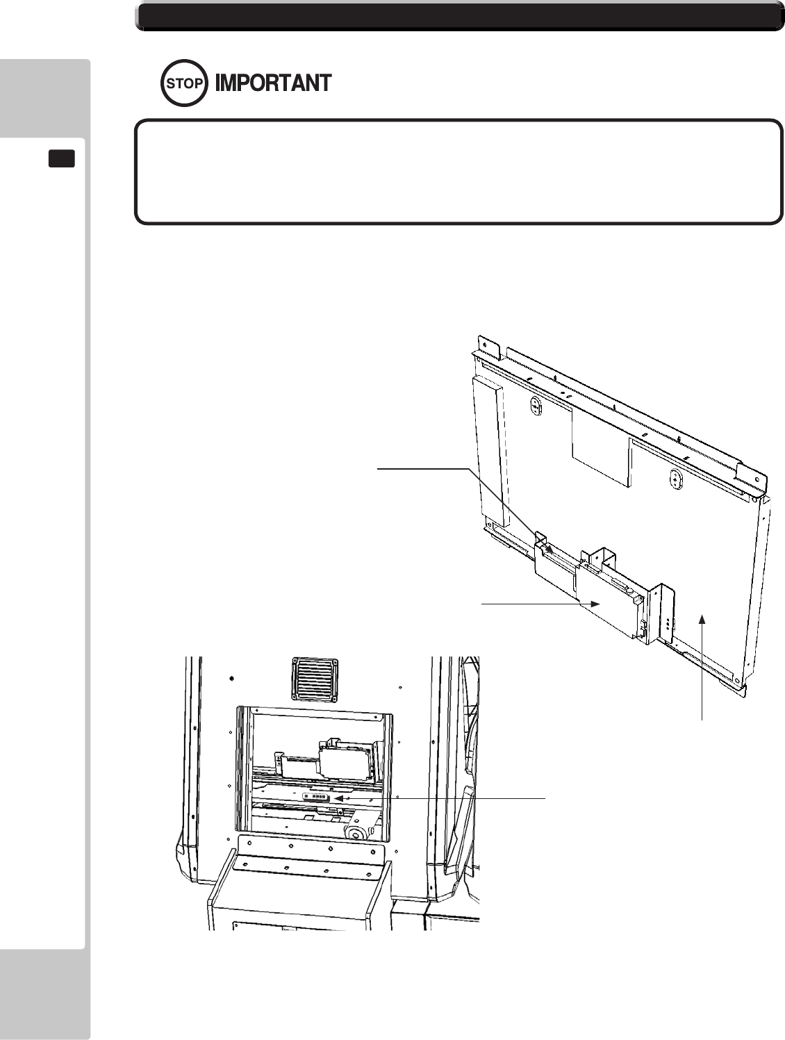
82
GRAPHICS DISPLAY
11
11-3 ADJUSTMENT METHOD
All adjustment values are set accurately at the time of shipping from the
factory. Do not readjust these values needlessly or apply adjustments not
specied in this manual. The display may not appear properly if the values
are incorrect.
CONTROL - ADJUSTMENT PROCEDURE
This sections explains basic control procedures for making adjustments using the buttons on
the 'Monitor Adjustment Board'
This Adjustment Board, and the
Monitor Power Supply are located
behind the Rear Door.
11-3Fig.02
11-3 Fig. 01
Power Supply
LCD Driver Bd
32” LCD Panel
LCD Controller PCB
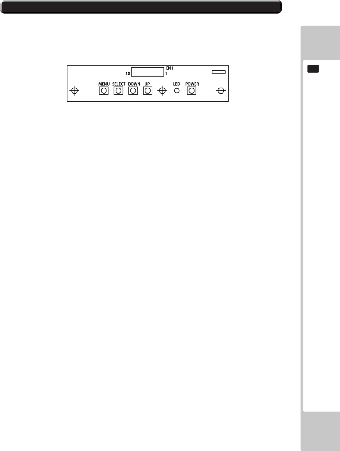
GRAPHICS DISPLAY
83
11
11-3 ADJUSTMENT METHOD
Button Names and Functions
MENU: Turn the Picture Menu display ON and OFF.
SELECT: Gains entry to the Item selected in the menu. (Highlights in Yellow when selected)
Exits the Item adustment. Any changes made during this
operation are actioned.
DOWN: Moves the cursor (Black Bar) down to select a menu item.
Decrease the value of, or change, a selected menu item.
UP: Move the cursor (Black Bar) up to select a menu item.
Increase the value of, or change, a selected menu item.
LED: LED illuminates green: Monitor is operating.
LED ashes red: Power is off.
POWER: Turns the LCD Display ON and OFF. (Usually, it’s not necessary to operate.)
11-3 Fig. 03
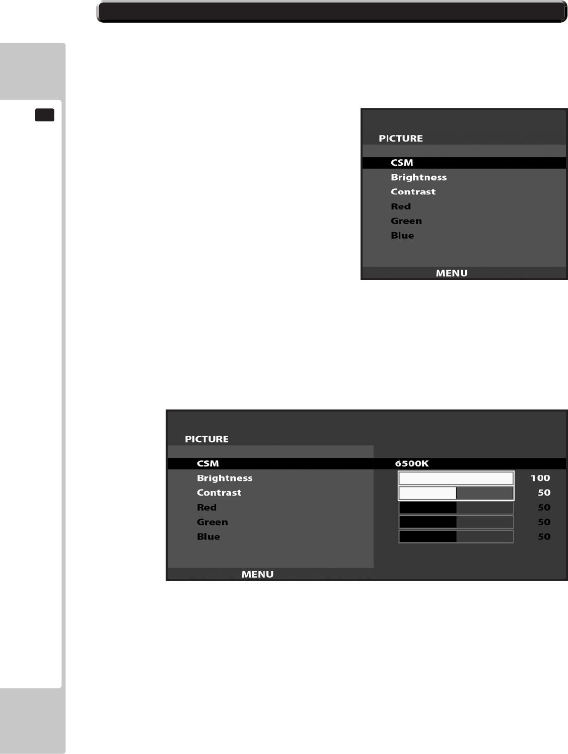
84
GRAPHICS DISPLAY
11
11-3 ADJUSTMENT METHOD
On-Screen Display (OSD)
Press the MENU Button while the OSD is not displayed to bring up the Picture Menu.
On the Picture Menu, it is possible to perform various screen adjustments.
Use the UP and DOWN Buttons to move the ‘Black Bar’to the item you want to adjust.
After selecting the desired item, pressing the SELECT Button will extend the MENU Screen and allow
adjustments to be changed.
Within each item, press the SELECT Button to exit the adjustment screen. The adjustment values at this time will be
saved simultaneously.
The current options are set at :
CSM - 6500K
Brightness - 100
Contrast - 50
11-3 Fig. 04
11-3 Fig. 05
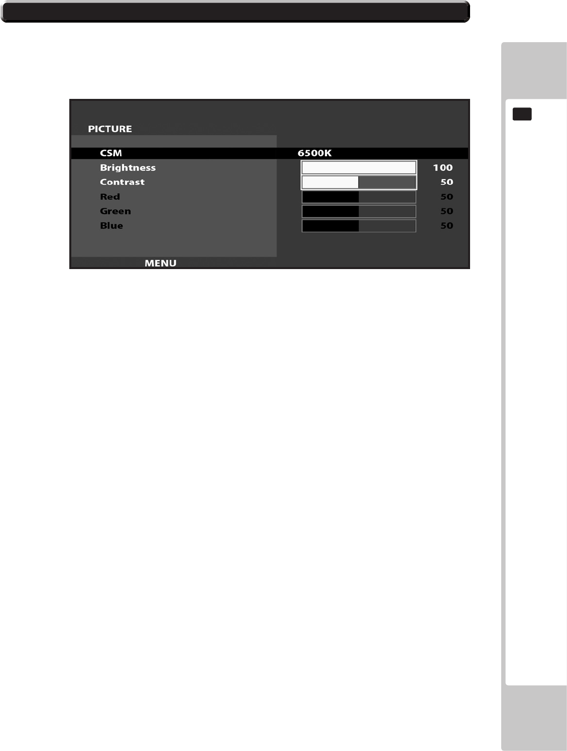
GRAPHICS DISPLAY
85
11
11-3 ADJUSTMENT METHOD
On-Screen Display (OSD) <continued>
AvailableSettings
CSM (Selects Operation Mode))
Selection availble - 6500K - 9300K - USER
BRIGHTNESS (Adjust Brightness)
Adjust screen Brightness. - Values: 0 - 100
(0” being the darkest setting, and “100” being the brightest)
CONTRAST (Adjust Contrast)
Adjust Contrast level. - Values: 0 - 100
(0” having the least amount of difference between light and dark, and “100” having the most)
NOTE : The Red, Green, and Blue adjustments are unavailable in the Mode of Operation selected on the Screen
shown in 11-3 Fig. 06. These adjustments can only be made is the CSM option is set to ‘User’.
11-3 Fig. 06
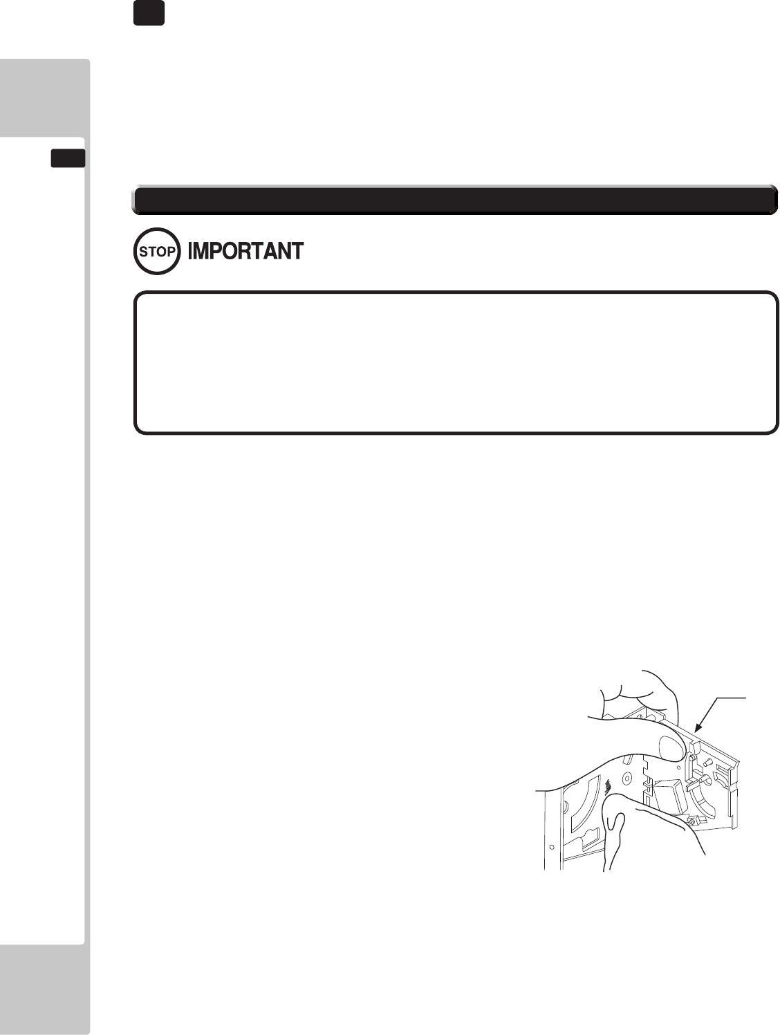
86
COIN HANDLING
12
IfthecoinisnotrejectedwhentheREJECTbuttonispressed,openthecoinchutedoorandopenthe
selectorgate.Afterremovingthejammedcoin,putanormalcoininandchecktoseethattheselector
correctlyfunctions.
TheCoinSelectorshouldbecleanedonceevery3months.
Whencleaning,followtheprocedurebelow:
12-1FIG1
● Remove and clean smears by using a soft cloth dipped in water or diluted
chemical detergent and then squeezed dry.
● Never apply machine oil, etc. to the Coin Selector.
● After cleaning the Coin Selector, insert a regular coin in the normal
working status and ensure that the selector correctly functions.
12-1 CLEANING THE COIN SELECTOR
GATE
Handling the Coin Jam
12 COIN HANDLING
1
2
3
TurnthepowerforthemachineOFF.OpentheCoinChuteDoor
RemovetheCoinSelectorfromtheCoinChuteDoor
Openthegateanddustoffbyusingasoftbrush(SmallsoftPaintBrush,etc.)
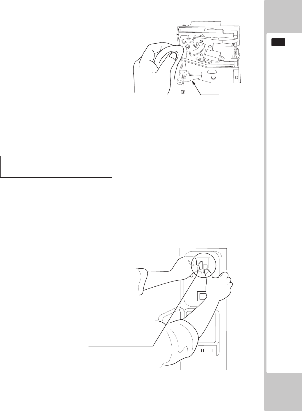
COIN HANDLING
87
12
Removeandcleansmearsbyusingasoftclothdippedinwaterordilutedchemicaldetergent
andthensqueezeddry.
RemovetheCRADLE..Whenremovingthe
retainingring(Ering)beverycarefulsoasnot
tobendtherotaryshaft.
Removestain from therotary shaftand shaft
receivingportionsbywipingoffwithasoft
cloth.etc.
Afterwiping off asper previous step,further apply adry clothto completely drythe Coin
Selector.
CLEANING THE COIN SELECTOR (MECHANICAL).
Onceeverymonth,whenperformingtheCoinSWTest,simultaneouslycheckthefollowing:
DoestheCoinMetercountsatisfactorily?
Doesthecoindropintothecashboxcorrectly?
IsthecoinrejectedwheninsertedwhilekeepingtheREJECTButtonpresseddown?
Coin Insertion Test
12-1 FIG 2
12-1FIG3
CRADLE
Insert a coin while keeping
the REJECT Button pressed
down and check if it is
rejected.
1
2
3
4
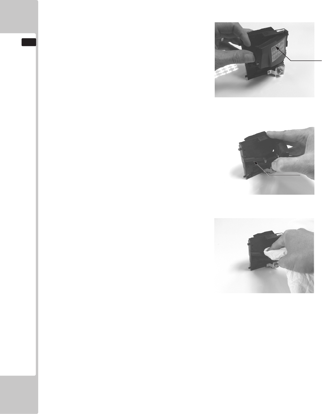
88
COIN HANDLING
12
Remove and clean smears by using a damp soft
cloth dipped in water. DO NOT use any diluted
chemical detergent or cleansing agent as this will
impair the workings of the component.
Open the reject gate to gain access to the rundown
path.
Remove the dirt and stains from the runway by
wiping off with a soft damp cloth.
After wiping off as per previous step, further apply
a dry cloth to completely dry the coin Selector.
CLEANING THE COIN SELECTOR (SR3) <continued>
1
2
3
4
GATE
RUNWAY
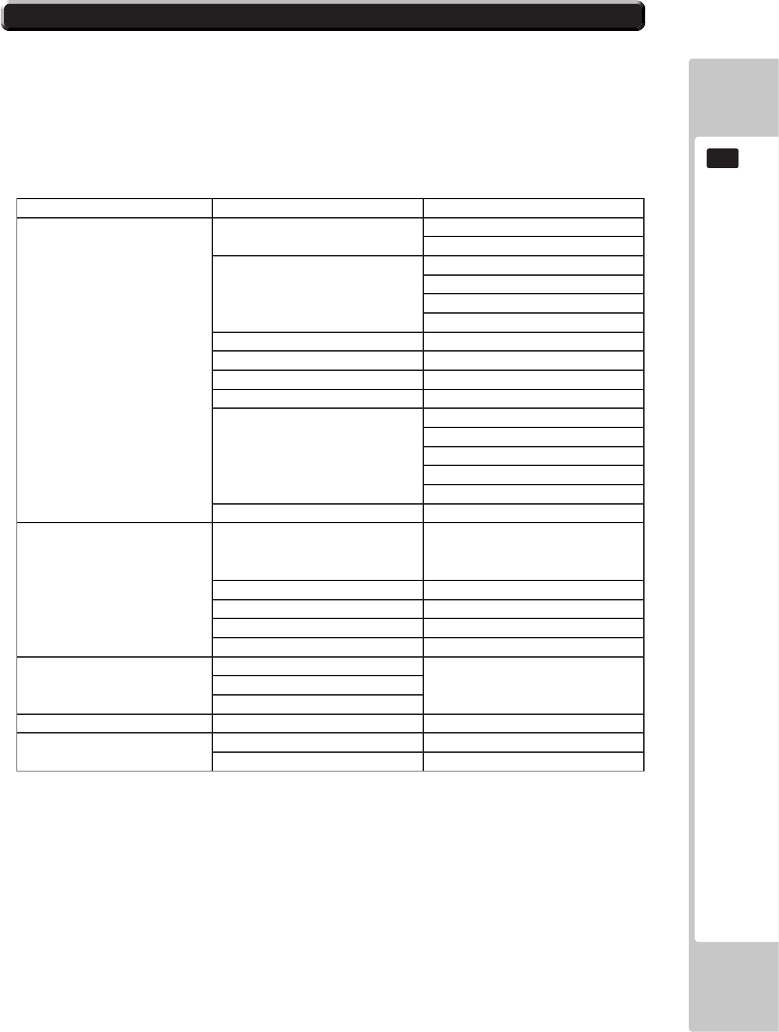
COIN HANDLING
89
12
12-2 FAULT FINDING
Fault Finding
The following information is presented for customers’ guidance in rectifying a fault but does not cover all possible
causes.
All acceptors with electronic faults should be returned to an approved service centre for repair.
SYMPTOM INVESTIGATE POSSIBLE CAUSE
Acceptor does not work
(all coins reject)
Connector Poor Contact
Loose Wire
Power Supply
Not switched on
Incorrect voltage
Inadequate current
Rise time too slow
Inhibit all inputs Acceptor Inhibited
Accept gate Gate not free or dislocated
Accept channel Obstruction
Reject gate Not fully closed
LED on rear cover RED
EEPROM chksm error
SR Sensor fault
Credit opto fault
Credit sensor blocked
Reject lever pressed
LED on rear cover YELLOW Reinstall power
Poor Acceptance
Power Supply Voltage less than 10v
(Voltage drops when coil
engages)
Accept gate Gate jam or dislocated
Connector Loose
Coin rundown Dirty
Bank Select Both banks enabled
Coin stick or jam in
acceptor.
Accept channel Acceptor dirty or may have
some damage
Accept gate
Regect gate
A true coin type rejects Label Coin not programmed
No accept signal Connector Loose or broken wire
Accept channel Path dirty or obstructed
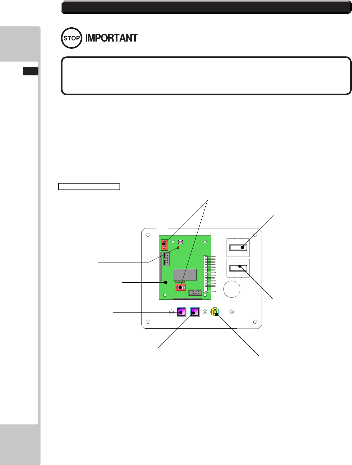
90
COIN HANDLING
12
ThisproductcomesequippedwithaMoneyControlsSR3CoinAcceptor.ToadjustthepriceofplayALL
creditsettingareadjustedviatheEXCELCREDITBOARD.
IMPORTANT!
TheCREDITSETTINGSwithintheSYSTEMTESTMODEmustbesetto1coin1credittoallowthe
CREDITBOARDtofunctioncorrectly.
TheVTSBDhasabuiltinCreditBoard.Thisiscontrolledby2DILSwitches.Theseallowtheoperatorto
selectthepriceofplay,typeofcoinacceptorandregion.
EXCEL Credit Board
12-3 ADJUSTING THE PRICE OF PLAY (EXCEL)
DILSW3(RegionalSettings)
AdjusttheseswitchestospecifythetypeofCoinAcceptorusedandcurrency.
Default=SW1&SW2ON-SR3inparallelmode,Sterling.
TESTBUTTON ProvidesaccesstotheTESTMENUwhenpressed.
SERVICEBUTTON ProvidesaSERVICECREDITwhenpressed
StatusLED Flasheswhenfunctioning.
CHANNEL1 ToCoinAcceptor(SR3TYPE.)
DILSW1(creditsettings) Adjusttorequiredpriceofpay.
VOLCONTROL MAINVOLUMEADJUSTMENT(FRONTSPEAKERS)
EXCEL CREDIT PCB
STATUS LED
TEST BUTTON
DIP SWITCHES
COUNTER 1
COUNTER 2
VOLUME CONTROL
SERVICE BUTTON
● The price of play is determined by the conguration of switches located
on either an EXCEL board or VTS board. The type of board used is determined
by product location. Switch settings for both types of board remain the same.
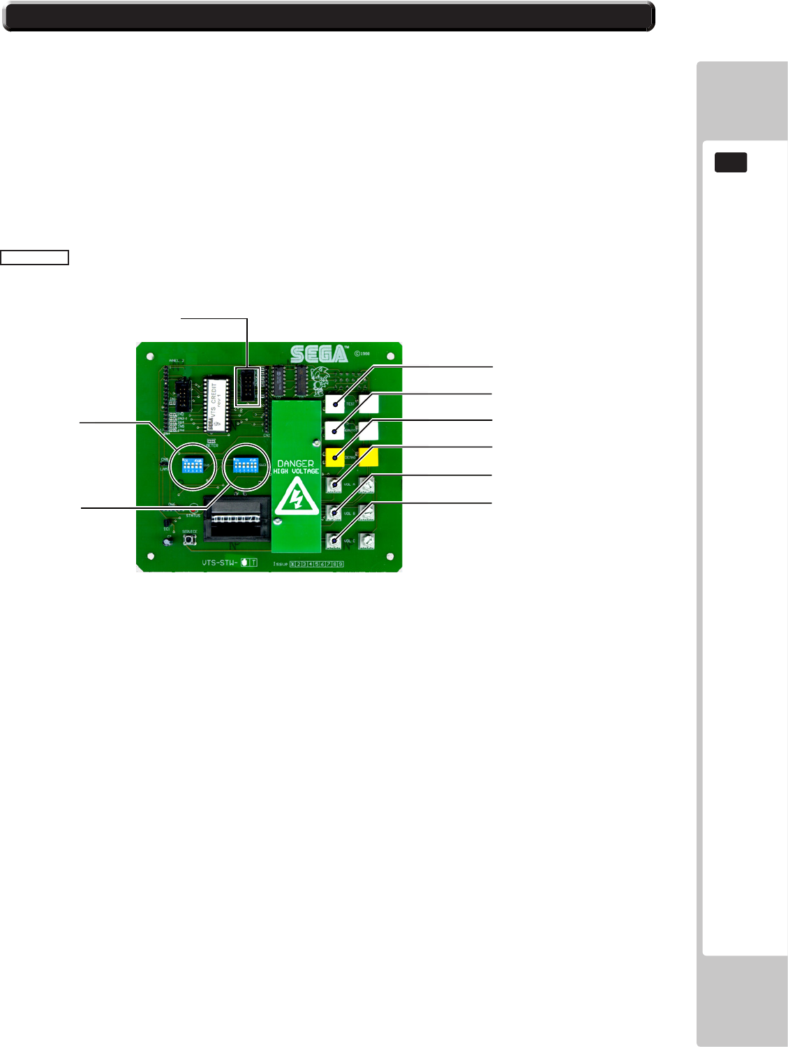
COIN HANDLING
91
12
ThisproductcomesequippedwithaMoneyControlsSR3CoinAcceptor.ToadjustthepriceofplayALL
creditsettingareadjustedviatheEXCELCREDITBOARD.
IMPORTANT!
TheCREDITSETTINGSwithintheSYSTEMTESTMODEmustbesetto1coin1credittoallowthe
CREDITBOARDtofunctioncorrectly.
TheVTSBDhasabuiltinCreditBoard.Thisiscontrolledby2DILSwitches.Theseallowtheoperatorto
selectthepriceofplay,typeofcoinacceptorandregion.
VTS Board
DILSW3(RegionalSettings)
AdjusttheseswitchestospecifythetypeofCoinAcceptorusedandcurrency.
Default=SW1&SW2ON-SR3inparallelmode,Sterling.
TESTBUTTON ProvidesaccesstotheTESTMENUwhenpressed.
SERVICEBUTTON ProvidesaSERVICECREDITwhenpressed
StatusLED Flasheswhenfunctioning.
CHANNELA ToCoinAcceptor(SR3TYPE.)
DILSW1(creditsettings) Adjusttorequiredpriceofpay.
DEMAG NOTUSED
VOLCONTROLA MAINVOLUMEADJUSTMENT(FRONTSPEAKERS)
VOLCONTROLB SECONDARYVOLADJUSTMENT(GUNSPEAKERS)
VOLCONTROLC NOTUSED
TEST BUTTON
SERVICE BUTTON
DEMAG (NOT USED)
VOLUME CONTROL A
VOLUME CONTROL B
VOLUME CONTROL C
DIP SW 3
DIP SW 1
COIN CHANNEL A
12-4 ADJUSTING THE PRICE OF PLAY (VTS)
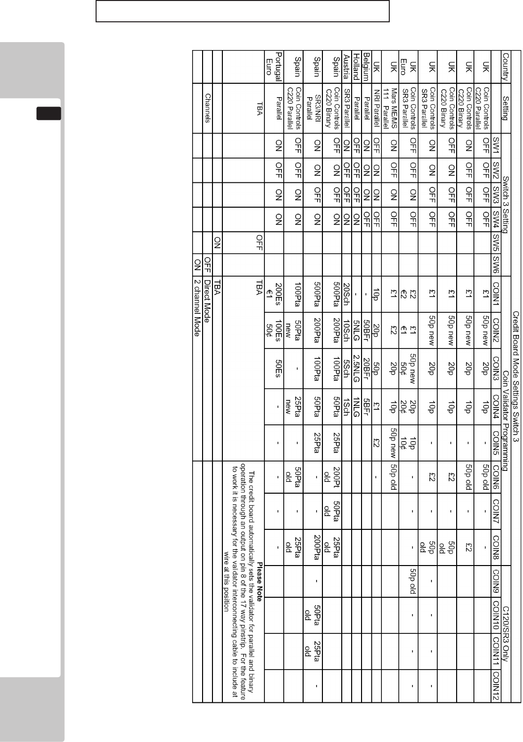
92
COIN HANDLING
12
REGIONAL AND ACCEPTOR SETTINGS (SW3)
Note:Theseswitchsettingsareunderconstantreviewandmaychangeduetoworldcurrencyupdates.
SetSW1accordingtotheoptionsettingsfoundintherelevantPriceofPlaySettingsTableonthefollowingpages.
SetSW3ontheVTS/Excelboardasshowninthetableabovecorrespondingtothecountryrequired.
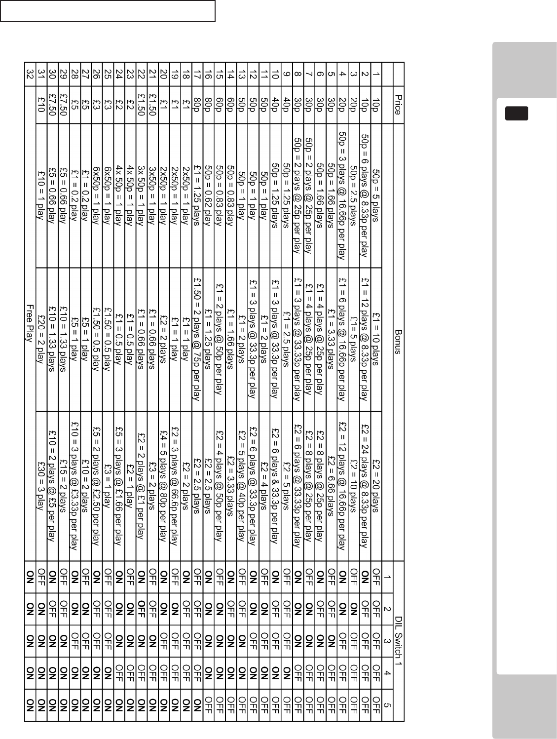
COIN HANDLING
93
12
STERLING PRICE OF PLAY SETTINGS (SW1)
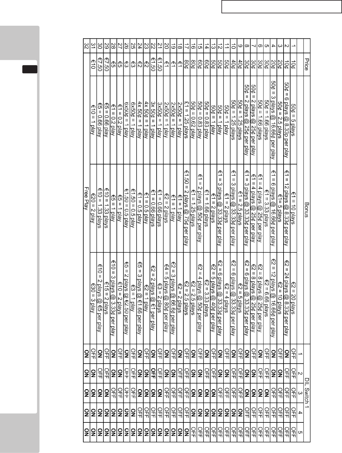
94
COIN HANDLING
12
EURO PRICE OF PLAY SETTINGS (SW1)
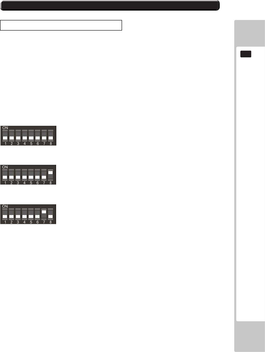
COIN HANDLING
95
12
BANK SELECT
This function allows you to enable both or individual select banks of coins via switches 7 and 8 on the
8 way DIL switch.
This enables the selection of 2 different currencies, one in each bank, or 12 coins/tokens in both banks
from the same country.
To enable/disable the banks set the switches as show below.
Both Banks ON (enabled) - Sterling and Euro’ s
Bank 1 ON (enabled) and Bank 2 OFF (disabled) - Sterling ONLY
Bank 1 OFF (disabled) and Bank 2 ON (enabled) - Euro’ s ONLY
Please remove power from the SR3 before changing the status on the DIP SW.
SELECTING STERLING / EURO OPTION
TheSR3coinacceptor(supplied)isprogrammedtoacceptUKSterlingandtheEuro.Factorysettingis
fortheUKSterling.IfthecongurationneedstochangetotheEuro,thenpleasefollowtheinstructions
belowforchangingovertotheEuroandvisaversa.
12-5 SR3 OPTIONS - STERLING / EURO SELECT
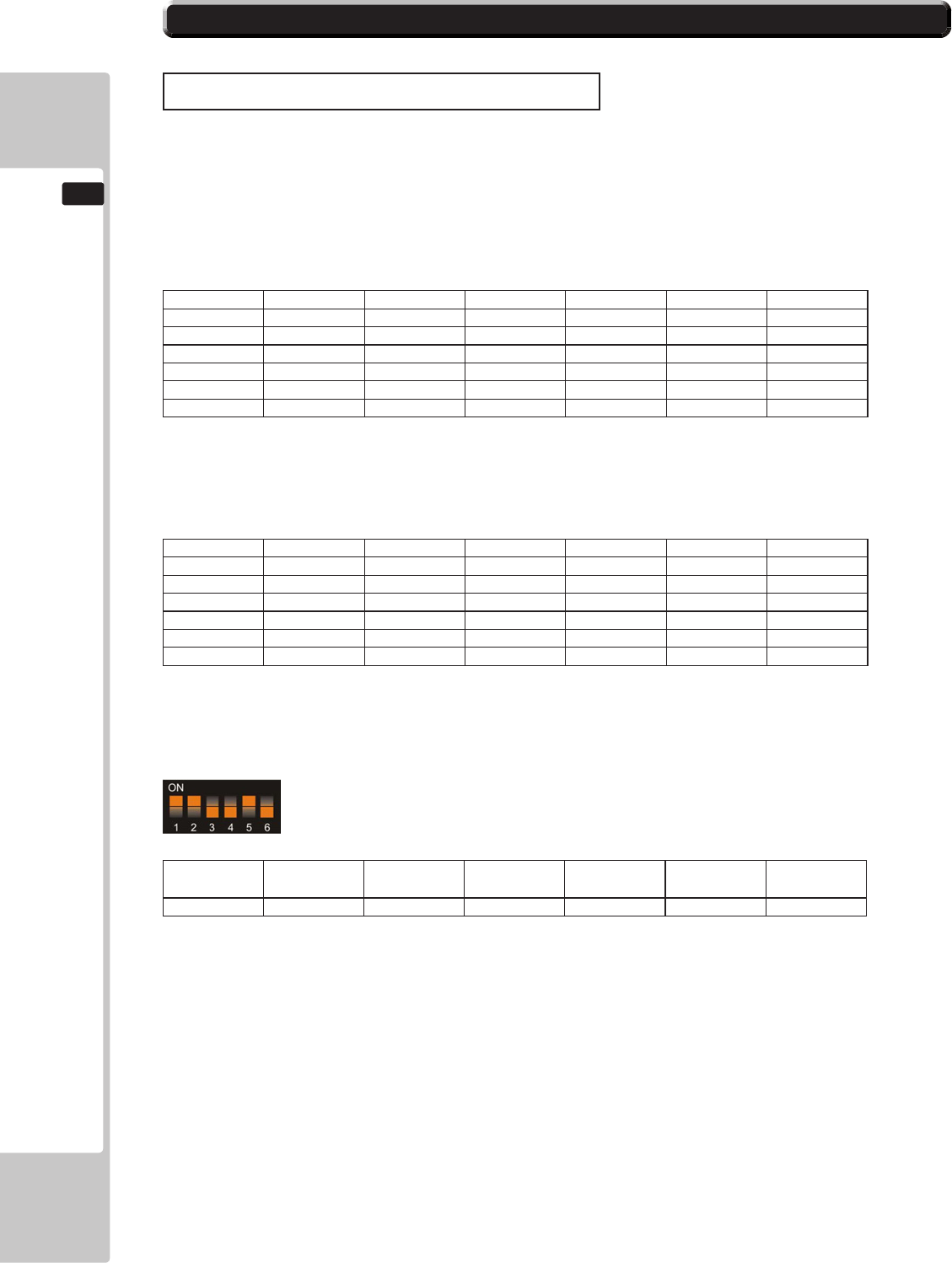
96
COIN HANDLING
12
Table 1: Teach & Run Programming Bank 1.
Coin Number SW1 SW2 SW3 SW4 SW5 SW6
1 o o o ON ON o
2 o o ON o ON o
3 o o ON ON ON o
4 o ON o o ON o
5 o ON o ON ON o
6 o ON ON o ON o
Bank 2
Table 2: Teach & Run Programming Bank 2
Coin Number SW1 SW2 SW3 SW4 SW5 SW6
7 o ON ON ON ON o
8 ON o o o ON o
9 ON o o ON ON o
10 ON o ON o ON o
11 ON o ON ON ON o
12 ON ON o o ON o
TeachandRunEXAMPLE.(Toteachcoinchannel12for£1)
SwitchoffthepowertotheSR3andsettheProgramDILswitchesto:-
MSB
SW1 SW2 SW3 LSB
SW4 TOTAL SW5 SW6
ON ON OFF OFF 12 ON OFF
SwitchonthepowertotheSR3.
Presstherejectleverwithin20seconds.TheLEDwillturnRED.
Startentering£1coinsuntiltheLEDashesGREEN,typicallyafter8to10insertions.
NOTE:IftheLEDturnsGREENafterthe1stcoin,thentheTeach&RunisDISABLED.
PresstherejectleverandtheLEDwillturnGREEN.Thecoinchannelhasnowbeen
programmed.
SET ALL SWITCHES TO THE OFF POSITION.
TEACH AND RUN PROGRAMMING (SR3)
Ifthe machine is positioned in location where only tokens are used, then the SR3 Coin Acceptor can be
programmed to accept and credit special coins/tokens.
Please follow the instructions below to enable and program the TEACH & RUN facility.
12-6 SR3 OPTIONS - TEACH AND RUN PROGRAMMING
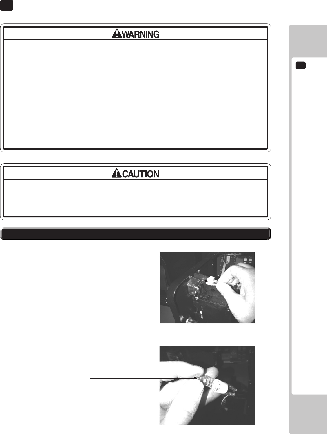
LAMPS AND LIGHTING
13
97
The Coin Door Lamp utilises a 12v 1.2w Wedge Bulb. It is important that youutilises a 12v 1.2w Wedge Bulb. It is important that you a 12v 1.2w Wedge Bulb. It is important that you
replace this bulb or any other bulb of that of the same voltage and rating.
Failing to observe this caution may result in PCB failure or possible re hazard.
• When working with the product, be sure to turn the power off. Working with the
power on may cause an electric shock or short circuit.
• You may get burned by a hot uorescent lamp or other lamps. Pay full attention
to the lamps when performing the work.
• Be sure to use lamps of the designated rating. Using lamps of undesignated
rating can cause a re or malfunctioning.
• There is the danger of short circuits or smoke generation due to deterioration
of insulation in lighting xtures resulting from age deterioration. Check for
anomalies such as the following: Does it smell like something is burning? Is there
socket discoloration? Are any lamps being replaced frequently? Do lamps not
go on properly?
Step 1. Open the Coin Door and locate the Lamp Housing
directly behind the Coin Insert Bezel.
Step 2. Hold the Lamp Housing rmly between your index
nger and thumb and gently pull upwards. Do Not try
to remove the Lamp Housing whilst holding the bulb as
the bulb may break causing injury.
Step 3. Once the Lamp Housing has been removed, carefully
hold the bulb between your ngers and pull the Lamp
Housing away.
Do not twist either bulb or Lamp Housing whilst removing the
bulb as this may cause damage to both bulb and or Housing.
Step 4. Simply push-t a replacement bulb of the same typeSimply push-t a replacement bulb of the same type
and follow these steps in reverse to ret.
13-1 COIN DOOR LAMP
Lamp Housing
Type: Wedge Bulb - 12v, 1.2w
13 LAMPS AND LIGHTING
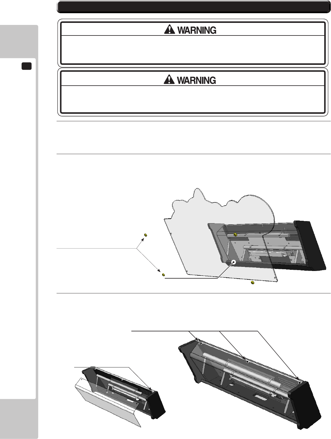
13
LAMPS AND LIGHTING
98
3
Remove the 3x Philips screws which secure the Lamp Cover to the Billboard. Carefully remove the Lamp
Cover taking care not cause damage. If possible, loosen the outer machine screws on both ends of the
Billboard to ease removal.
1
The Billboard Fluorescent Tube is located inside the back section of the Billboard Base, before attempting
to change the Tube, TURN THE POWER OFF.
2
To gain access to the Fluorescent Tube, extract the four xing screws which hold the Billboard Title Panel
in place and remove the cover.
13-2 FLUORESCENT TUBES - BILLBOARD
THIS WORK ON TOP OF THE CABINET, SHOULD NOT BE UNDERTAKEN WITHOUT THE
USE OF A SUITABLE STEP OR FOOTSTOOL.
MAKE SURE THAT THE MAIN SUPPLY VOLTAGE TO THE MACHINE IS SWITCHED OFF
BEFORE ATTEMPTING TO CARRY OUT THIS WORK
Remove the 4 fixings and washers
which secure the Title Panel.
Title Panel
Remove the 3 fixings which secure the
Lamp Cover to the Billboard.
Outer Machine Screws
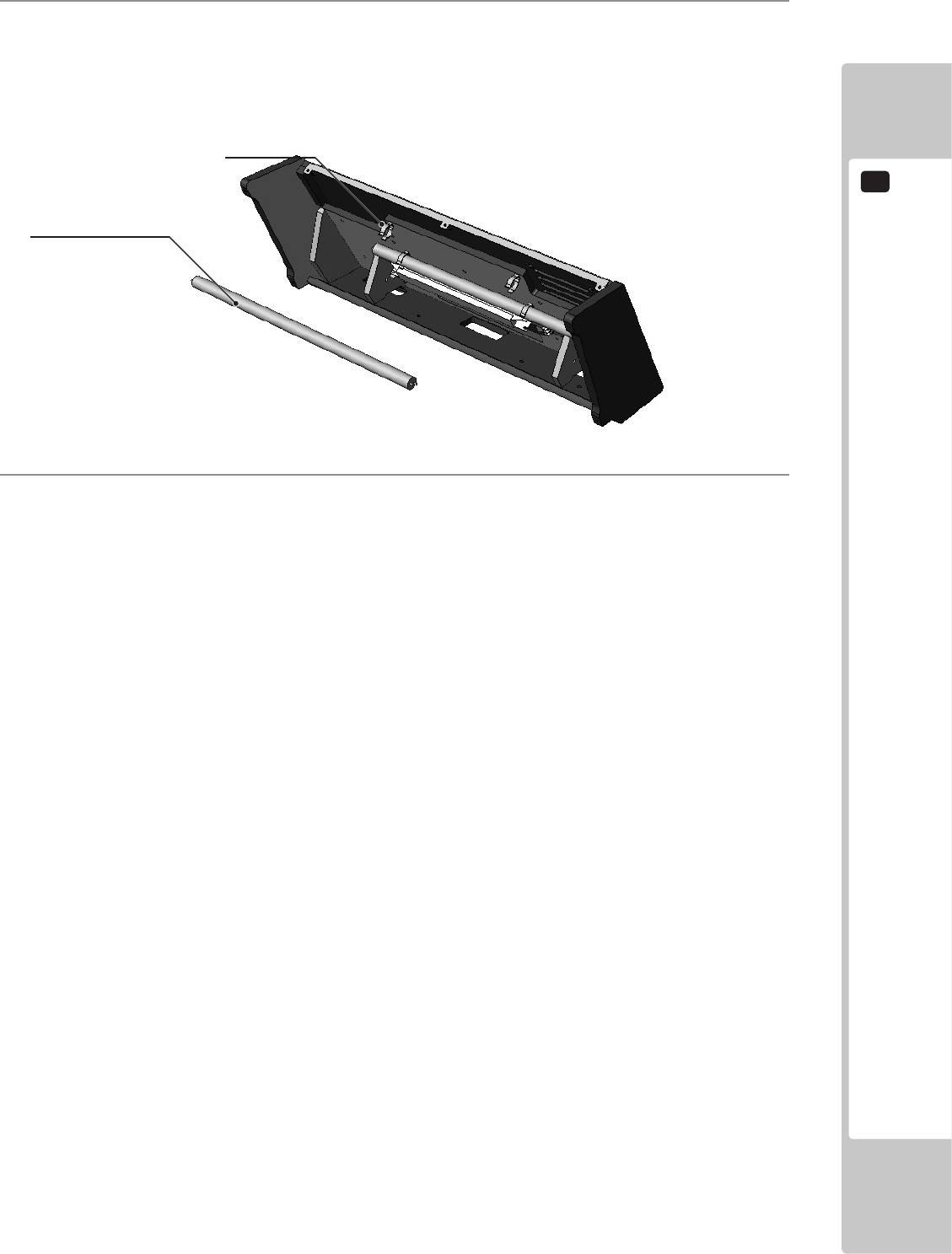
LAMPS AND LIGHTING
13
99
3
Once the cover is removed, disconnect the y-lead connectors from either end of the Fluorescent Tube and
carefully unclip it from the Terry Clips removing it from the machine.
Due to the possible risk of broken Glass during this procedure, protective clothing should be worn.
4
Replace the Fluorescent Tube with a new one of the same type and re-assemble the Billboard in the reverse
order.
Terry Clip
Fluorescent Lamp
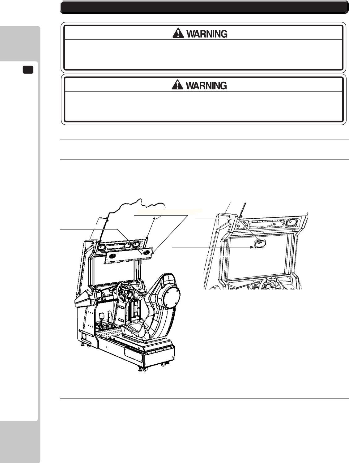
13
LAMPS AND LIGHTING
100
13-3 RACE LEADER LED
1
The RACE LEADER Lamp is a strip of bright white LED’s mounted on a PCB.
2
To gain access to the RACE LEADER Lamp, extract the nine xing screws marked which hold the Speaker
Panel in place and remove.
THIS WORK ON TOP OF THE CABINET, SHOULD NOT BE UNDERTAKEN WITHOUT THE
USE OF A SUITABLE STEP OR FOOTSTOOL.
MAKE SURE THAT THE MAIN SUPPLY VOLTAGE TO THE MACHINE IS SWITCHED
OFF BEFORE ATTEMPTING TO CARRY OUT THIS WORK
Speaker Panel
Fixing Points x 9
Fixing Points x 8
3
Locate the 2 oval speakers positioned above the display. Disconnect and extract both speakers by removing
the 8 xings which secure the speaker to the cabinet. (4 xings per speaker)
Speaker
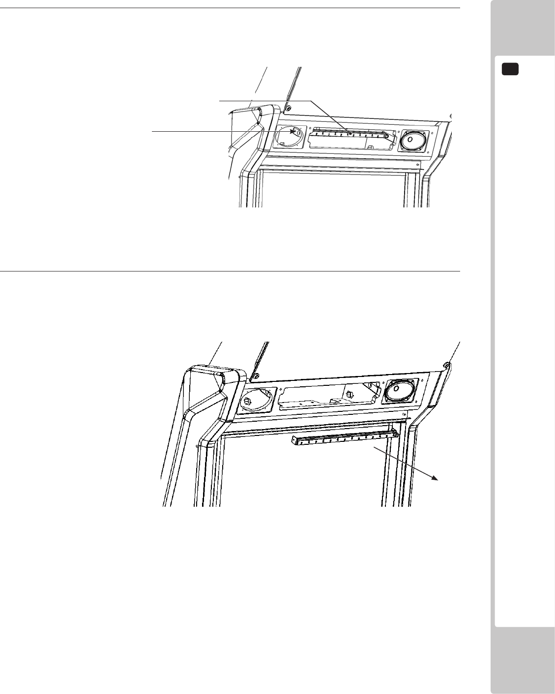
LAMPS AND LIGHTING
13
101
4
Once the speakers have been removed, locate the LED Bar and remove the xings at both ends of the
assembly. Access is available through the speaker area.
LED BAR
Fixing Points x 1
5
Once both xings have been removed, carefully pull out the LED bar and Bracket towards you until
restricted by the harness. Disconnect and remove.
RACE LEADER LAMP <continued>
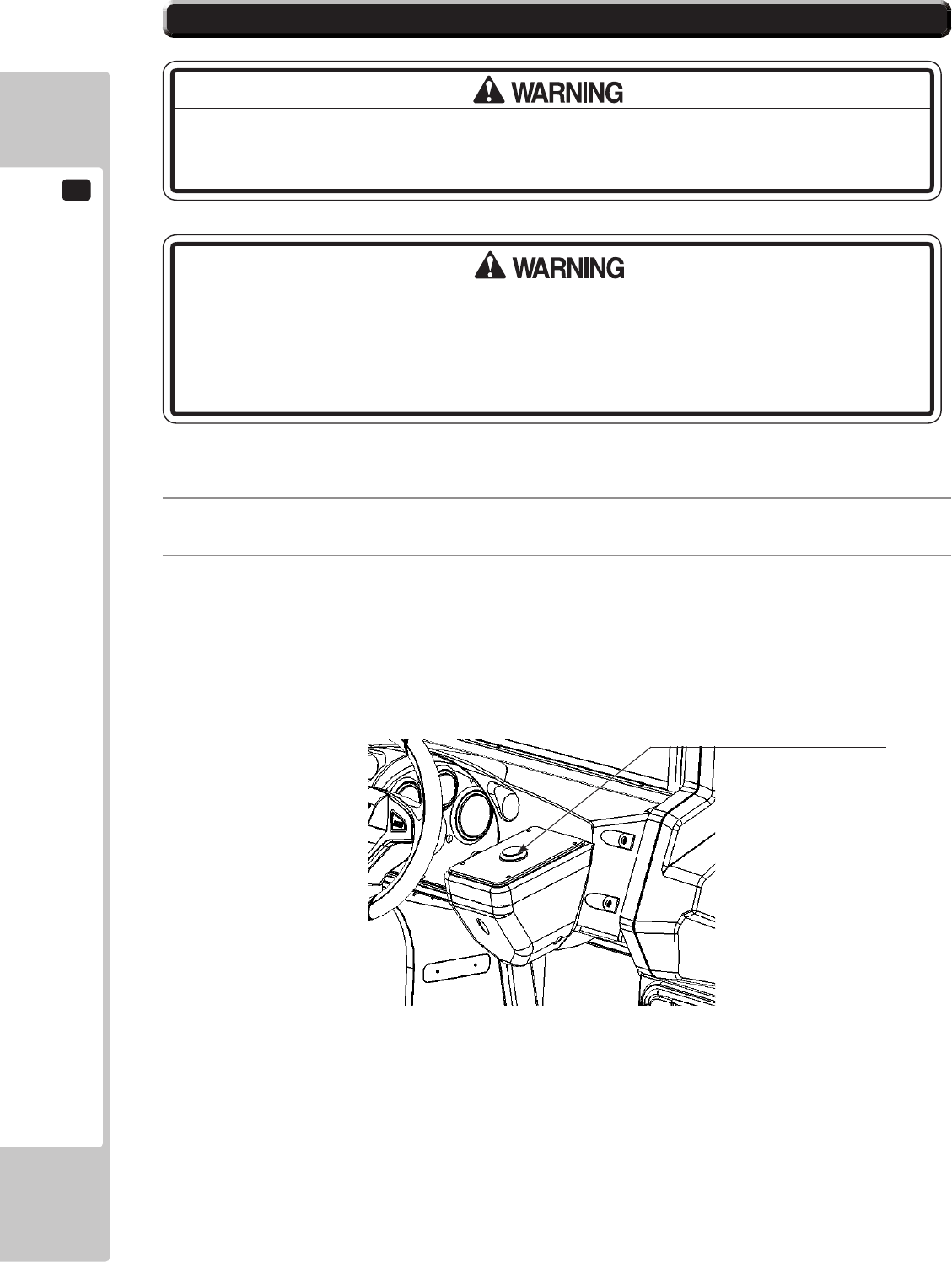
13
LAMPS AND LIGHTING
102
13-4 START LAMP
MAKE SURE THAT THE MAIN SUPPLY VOLTAGE TO THE MACHINE IS SWITCHED
OFF BEFORE ATTEMPTING TO CARRY OUT THIS WORK
1
Locate the Start Button housing positioned on the right hand side of the cabinet and on the right of the
Steering Wheel.
2
Access to the Start Switch and Lamp housing is gained by rst removing the Start Button Plate..
THE START LAMP IS A 12V (White) LED TYPE. IT IS IMPORTANT THAT YOU
REPLACE THIS LAMP WITH A LAMP OF THE SAME SPECIFICATION. REPLACING
THE LAMP WITH A FILAMENT BULB OR A LED OF A DIFFERENT SPECIFICATION
MAY RESULT IN PCB FAILURE OR EVEN A FIRE HAZARD.
Start Switch and Lamp housing
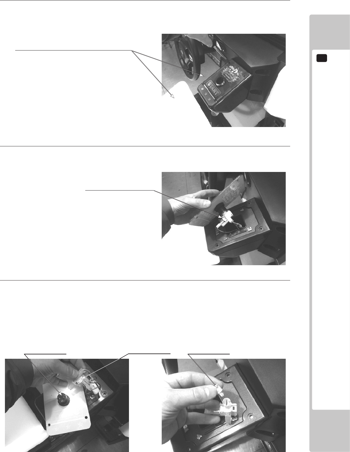
LAMPS AND LIGHTING
13
103
3
Remove the Button Plate from the Control Panel to gain access to the Switch and Lamp housing.
4
Once the Button plate has been removed to reveal the Switch and Lamp housing take care as not to pull on
the assembly as damage to the harness may occur.
5
Holding the Lamp Housing between your index nger and thumb, gently pull on the housing to remove it
from the Button enclosure. Always hold rmly onto the housing and never the wires.
To remove the lamp from the lamp hosing, gently pull on the lamp to remove. The Lamp is a push-t and
should never be twisted whilst in its housing.
Replace the lamp with a lamp of the same type and reassemble following these instructions in revers order.
Remove the (4) M4 Security Torx
screws which secure the button plate
to the Control Panel housing.
Switch and Lamp Housing
Switch and Lamp Housing Lamp - LED 12Vdc (White)
Button Housing
14
PERIODIC INSPECTION
104
• Every 6 months check to see if power cords are damaged, the plug is securely
inserted, dust is accumulated between the socket outlet and the power plug, etc.
Using the product with accumulated dust in the interior may cause re or electric
shock.
• Never use a water jet, etc. to clean the inside and outside of the cabinet. If
wetness occurs for any reason, do not use the product until it has completely
dried.
• Once a year, request the ofce shown on this manual or the dealer from whom
the product was originally purchased to perform the internal cleaning. Using the
product with accumulated dust in the interior may cause re or other accidents.
Note that you are liable for the cost of cleaning the interior parts.
• There is the danger of accidents involving electrical shorts circuits or fire
caused by factors such as the deterioration of insulation in electrical and
electronic equipment over time. Check that there are no abnormalities such as
odors from burning.
The items listed below require periodic check and maintenance to retain the performance of this machine and to
ensure safe business operation.
When handling the controller, the player will be in direct contact with it. In order to always allow the player to enjoy
the game, be sure to clean it regularly. Also, it is advisable to provide wet tissue, etc. available for player use.
14 TABLE 01 PERIODIC INSPECTION TABLE
ITEMS DESCRIPTION PERIOD
CABINET Conrm that adjusters contact
oor
Daily
CONTROL PANEL
STEERING WHEEL
Volume inspection Monthly
Gear alignment inspection Every 3 months
Greasing Every 3 months
SHIFT LEVER Switch inspection Monthly
Greasing Every 3 months
START BUTTON Switch inspection Every 3 months
ACCELERATOR & BRAKE Volume inspection Monthly
Gear and spring potion greasing Every 3 months
MONITOR Screen cleaning Weekly
Conrm settings Monthly or
when moving
COIN CHUTE DOOR Coin switch inspection Monthly
Coin insertion test Monthly
Selector cleaning Every 3 months
SEAT Greasing to the seat rail Every 3 months
GAME BOARD Conrm settings Monthly
POWER CABLES Inspection, Cleaning 6 months
INTERIOR Cleaning Yearly
CABINET SURFACES Cleaning As appropriate
14 PERIODIC INSPECTION
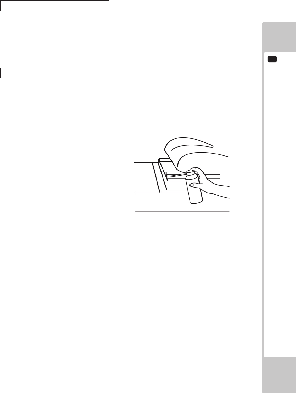
PERIODIC INSPECTION
14
105
Cleaning the Cabinet Surfaces
When the cabinet surfaces are badly soiled, remove stains with a soft cloth dipped in water or diluted (with water)
chemical detergent and squeezed dry. To avoid damaging surface nish, do not use such solvents as thinner, benzine,
etc. other than ethyl alcohol, or abrasives, bleaching agent and chemical dustcloth.
Some general-purpose household, kitchen and furniture cleaning products may contain strong solvents that degrade
plastic components, coatings, and print. Before using any cleaning product, read the product's cautionary notes
carefully and test the product rst on a small area that is not highly visible.
Seat (Greasing to Seat Rail Portion)
Move the Seat to the rear most position and apply spray greasing to the portion shown at the right once every 3
months using NOK KLUBER L60 or GREASE MATE SEGA PART No. 090-0066.
After greasing, move the Seat a few times forward and backward so as to allow the grease to be applied all over
uniformly.
Be sure to wipe grease which attaches to the surfaces of the PROTECT RUBBER on the Seat Rail, or any excess
grease.
15
TROUBLESHOOTING
106
15-1
TROUBLESHOOTING (WHEN NO ERROR MESSAGE IS SHOWN)
• In order to prevent electric shock and short circuit, be sure to turn power off
before performing work.
• Be careful so as not to damage wirings. Damaged wiring can cause electric
shock or short circuit.
• After removing the cause of the functioning of the Circuit Protector, reinstate
the Circuit Protector. Depending on the cause of the functioning, using the Circuit
Protector as is without removing the cause can cause generation of heat and re
hazard.
• In the event that a problem cannot be resolved by employing the procedures
listed in this Manual, be sure to request service from the office shown on this
Manual or the dealer from whom the product was originally purchased. Attempts
to employ procedures other than those specified in this Manual can cause
electrical shock, shorting, or re.
• In the event of a problem that is not described here, be sure to contact the
ofce shown on this Manual or the dealer from whom the product was originally
purchased. Careless attempts at repair can result in electrical shock, shorting, or
re.
If a problem occurs, rst check to make sure that the wiring connectors are properly connected.
15 TABLE 01
PROBLEM CAUSE COUNTERMEASURES
When the main SW is
turned ON, the machine
is not activated.
The power is not ON. Firmly insert the plug into the outlet.
Incorrect power source/voltage. Make sure that the power supply/voltage
are correct.
The Fuse on the AC Unit has blown
due to momentary over current.
After eliminating the cause of overload,
replace the specied rating fuse.
The fuse of the connect board has
blown due to momentary over
current.
After eliminating the cause of overload,
replace the specied rating fuse.
Fluorescent lamp inside
Billboard Unit not
lighting
Connector connection fault. Check connections to the Billboard Unit.
Fluorescent lamp and glow lamp need
replacement.
Replace the uorescent lamp and the
glow lamp.
15 TROUBLESHOOTING
TROUBLESHOOTING
15
107
Sound is not emitted. Sound volume adjustment is not
correct
Adjust the Switch Unit’s sound
adjustment volume.
Faulty connections for various
connectors
Check the connections for the game
board, amp, speakers and Volume
connectors
Malfunctioning BD, amp and speaker Perform Sound Test.
Sounds are emitted and
the lamps are lit, but the
screen is black.
Faulty connections for the visual
signal connector or the monitor power
connector
Check the connections for the monitor
and game board connectors.
Faulty LCD Display See Chapter 11
Colors on the monitor
screen are strange.
Faulty connection for the visual signal
connector.
Check the visual signal connector
connection and make sure it is secured
properly.
Screen adjustment is not appropriate. Make adjustment appropriately.
The on-screen image
sways and/or shrinks.
The power source and voltage are no
correct.
Make sure that the power supply and
voltage are correct.
Does not accept input
from any switch or
volume.
Faulty connector connections. Check the connection for the I/O Board
and Cabinet connector.
Check the power for the I/O Board.
Steering (Servomotor)
response is incorrect.
Incomplete power on check. Power on and verify that the power on
check completes properly.
Deviation of the volume value. Adjust the volume value in the Test
Mode.
Volume gear engagement fault. Adjust the engagement of the gear.
Volume malfunctioning. Replace the volume.
Detached wires. Check for faulty wire connections around
moving parts.
When replacing wires, secure them so
that they do not touch any moving parts.
No response from
Steering (Servomotor).
Failure of power-on checking
procedure.
Reconnect the power and complete a
power-on checking procedure.
Faulty connector connections. Check the connections for the connectors
between the Game Board and Servodriver
and between the Servodriver and the
Servomotor.
Thermal element in the Servodriver is
operating.
Occurs when the internal temperature
reaches 70°C (158°F) and corrects
automatically when the unit cools.
Momentary overload caused a fuse on
the Servodriver to blow.
Contact the company from whom the unit
was purchased.
15
TROUBLESHOOTING
108
Steering (Servomotor)
is weak in its force
feedback
Ageing of the force feedback
mechanism
Reset in the Test Mode.
Does not accept input in
from the Reset Button
unit.
Faulty connector or connections. Check the connections between the I/O
Board, the Cabinet and the Reset Button
Unit
Faulty Microswitch Replace Microswitch
The accelerator or
brake does not perform
appropriately.
Incorrect volume setting. Adjust the volume value in the Test
Mode.
Faulty Volume attachment or adjust
gear alignment.
Adjust the volume attachment and verify
in Test Mode.
Faulty connector or connections. Check the connections for the accelerator
and brake connectors and the connectors
between the accelerator, brake and
cabinet.
Failure of the volume. Replace the volume.
Start button input does
not work and they do
not ash.
Faulty connector or connections. Check the connections for the connectors
between the I/O Board, the cabinet and
the control panel and those inside the
control panel.
Start button input
works, but they do not
ash.
Unveried settings or operation. The Start button only ashes when Free
Play is set. Check the operation in Test
Mode.
The lamp is blown. Replace the lamp.
Failure of the network
play.
Network play is wrongly set. Reset correctly.
Communication cables are
disconnected.
Communication cables are wrongly
connected.
Reconnect the cables.
Damage of communication cables. Replace the cables. Contact the company
from whom the unit was purchased.
TROUBLESHOOTING
15
109
• In case fuse replacements other than those stated in this manual are
necessary, contact where you purchased the product from for inquiries regarding
this matter.
• In order to prevent an electric shock, be sure to turn power off and unplug
from the socket outlet before performing work by touching the internal parts of the
product.
• Be careful so as not to damage wirings. Damaged wiring can cause electric
shock and short circuit accidents.
• Be sure to use fuses meeting specified rating. Using fuses exceeding the
specied rating can cause re and electric shock accidents.
• After eliminating the cause of the blowing of fuse, replace the fuse. Depending
on the cause of fuse blowing, continued use with the fuse as is blown can cause
generation of heat and re hazard.
Replacing Fuses
Fuses are located on the following:
RD-1540UK Assy AC Unit (1) 5A Time Delay 20mm
(1) 5A Time Delay 20mm (Spare)
838-14551-02UK AC Distribution PCB (2) 6.3A Time Delay 20mm
110
GAME BOARD
16
● When working with the product, be sure to turn the power off. Working with the
power on may cause an electric shock or short circuit.
● Be careful not to damage the wires. Damaged wires may cause an electric
shock, short circuit or present a risk of re.
● Do not use this product with connectors other than those that were connected
and used with the game board at the time of shipping. Do not carelessly connect
wires to connectors that were not used at the time of shipping, as this may cause
overheating, smoke or re damage.
In this product, setting changes are made during the test mode. The game board
need not be operated. Use the game board, etc. as is with the same setting made
at the time of shipment so as not to cause electric shock and malfunctioning.
Static electricity from your body may damage some electronics devices
on the IC board. Before handling the IC board, touch a grounded metallic
surface so that the static electricity can be discharged.
16 GAME BOARD (RINGWIDE)

GAME BOARD
111
16
16-1 HANDLING PRECAUTIONS
● To prevent electric shock or IC Board malfunctioning, be sure to turn off the
power for the cabinet when installing or removing the IC Board.
● Extraneous matter such as dust on the IC Board can cause the IC Board to
generate heat and result in a re due to short circuit, etc. Ensure the IC Board
surfaces are always kept clean.
● Keep the IC board well cooled. RINGWIDE is provided with ventilating fans. Do
not block the air outlets of these fans. Also do not place anything closely to
RINGWIDE. Failure to observe these instructions may cause an overheating and
re.
● Always follow the usage conditions from SEGA as well as the usage conditions
for the cabinet you are using for RINGWIDE. Failure to do so may cause an
overheating and re.
● Be sure to connect the IC Board and connectors completely. Insufcient
insertion can damage IC Board, etc.
● For the IC Board circuit inspection, only the use of Logic Tester is permitted. The
use of ordinary testers is not permitted as these can damage the IC Board.
● Do not subject the IC Board to static electricity when installing the IC Board in
the cabinet or when connecting wire harness connectors to the IC Board.
● When soldering buttons, etc. to the wire harnesses, be sure to remove the wire
harnesses from the IC Board so as not to subject the IC Board to heat.
● Using RINGWIDE without the Shield Case can cause electric wave trouble. Be
sure to use RINGWIDE together with the accessory Shield Case.
● Some parts are the ones designed and manufactured not specically for this
product. The manufacturers may discontinue, or change the specications of,
such general-purpose parts. If this is the case, SEGA cannot repair or replace a
failed product whether or not a warranty period has expired.
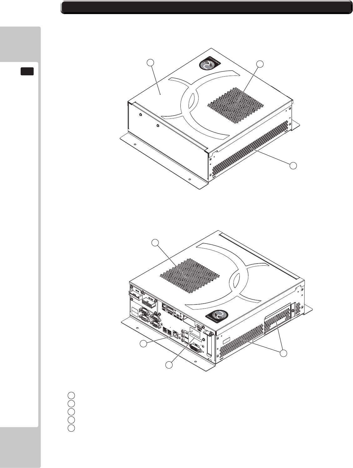
112
GAME BOARD
16
16-2 PARTS DETAILS
1
2
2
4
5
3
2
3
Shield case
Exhaust vent (Do not block or cover.)
Intake vent (Do not block or cover.)
Board number
Board serial number
1
2
3
4
5
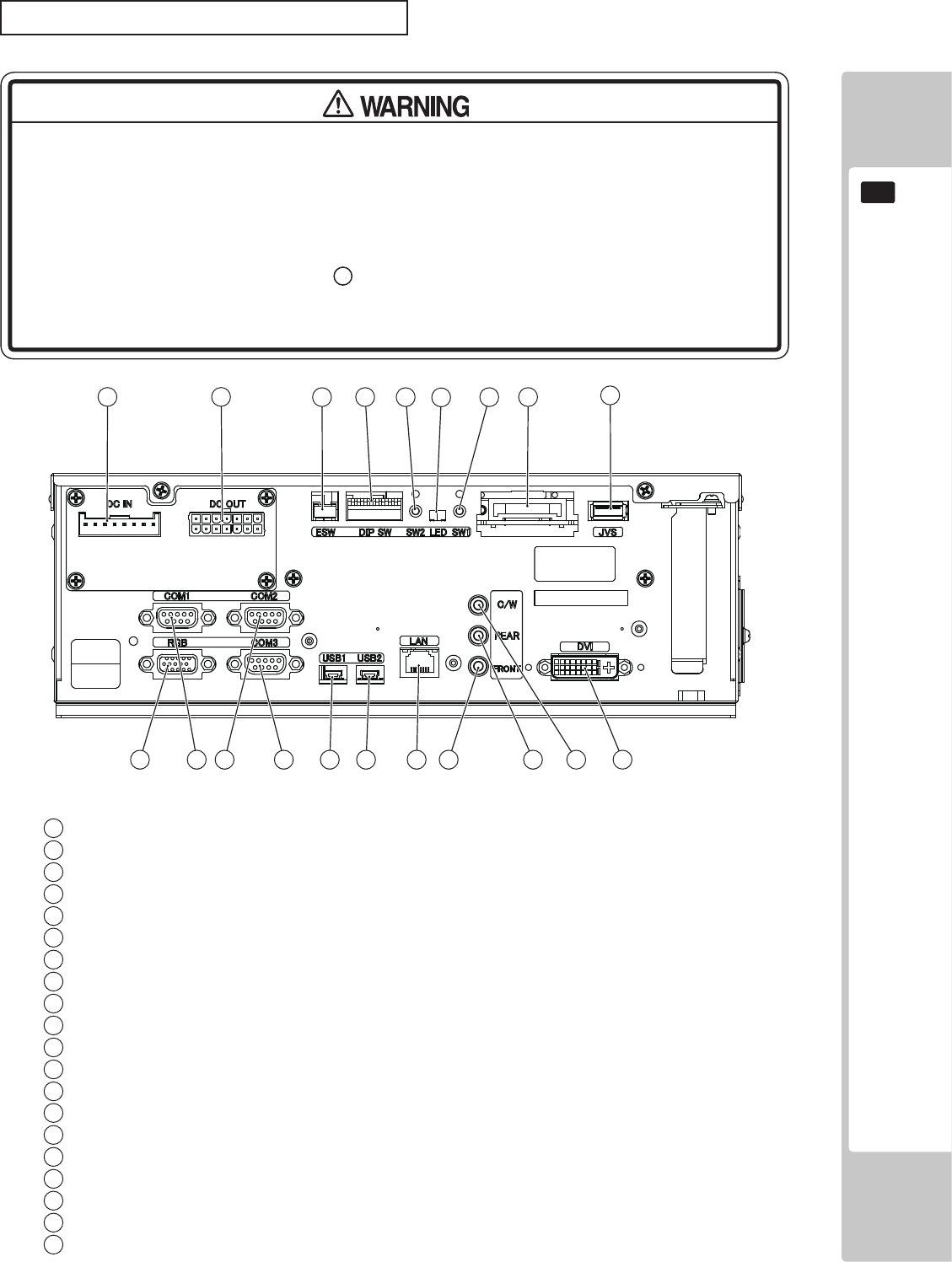
GAME BOARD
113
16
CONNECTORS, SWITCHES AND LED
● When connecting the connector, check the orientation and type carefully and
connect securely. The connector must be connected in the proper direction
and type. If it is connected in the wrong direction or indiscriminately at an
incline, or connected wrong connector, so that a load is applied, the
connector or its terminal pins could break, causing a short circuit or re.
● Do not connect components to 9 JVS I/O that are not designated by SEGA.
Connecting unspecied components could cause an accident such as an
electric shock or re.
123
2
20 2
19 2
18 2
17 2
16 2
15
56
4
11
9
2
12
2
13
2
14
78
10
Power input port
External power supply port
Test/Service button external input port
DIP SW (Dip switches)
Service button (SW2)
LED1, LED2 (From right to left: 1, 2)
Test button (SW1)
Key chip socket
JVS I/O port
DVI output
Center/Woofer lineout
Rear lineout
Front lineout
LAN port
USB port 2
USB port 1
Serial communication port 3
Serial communication port 2
Serial communication port 1
RGB output
1
2
3
4
5
6
7
8
9
10
12
13
14
15
16
17
18
19
20
11
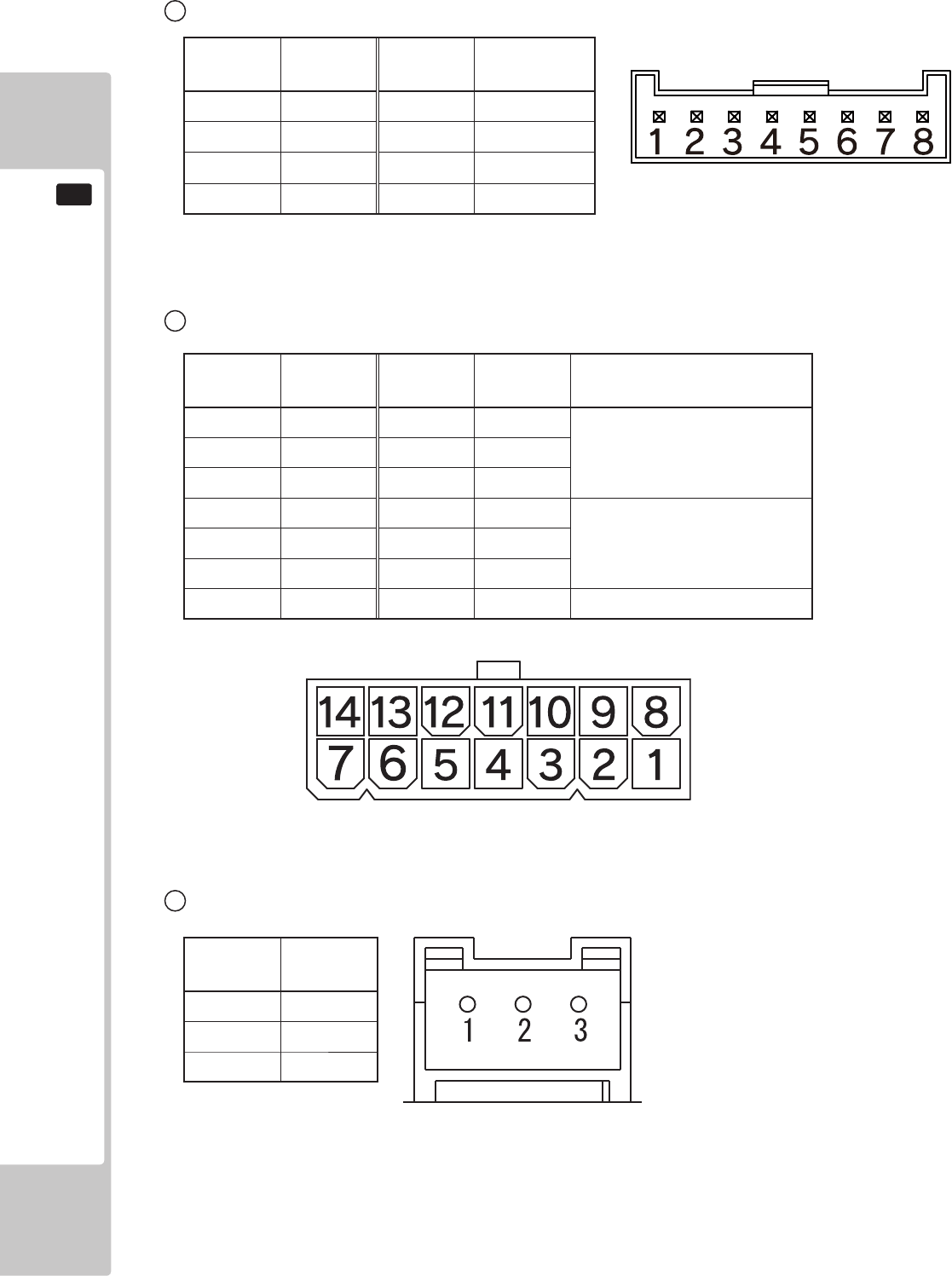
114
GAME BOARD
16
Terminal
No.
Signal
Name
1 SW1
2 SW2
3 GND
Terminal
No.
Signal
Name
Terminal
No.
Signal
Name Maximum Output Current
1 GND 8 +12VDC
2.3A2 GND 9 +12VDC
3 GND 10 +12VDC
4 GND 11 +5VDC
2.3A5 GND 12 +5VDC
6 GND 13 +5VDC
7 N.C. 14 N.C. -
1 Power Input Port
2 External Power Supply Port
Terminal
No.
Signal
Name
Terminal
No. Signal Name
1 GND 5 +12VDCIN
2 GND 6 +12VDCIN
3 GND 7 +12VDCIN
4 GND 8 +12VDCIN
3 Test/Service Button External Input Port
NOTE: Before connecting, be sure to check the type of connector.
NOTE: Before connecting, be sure to check the type of connector.
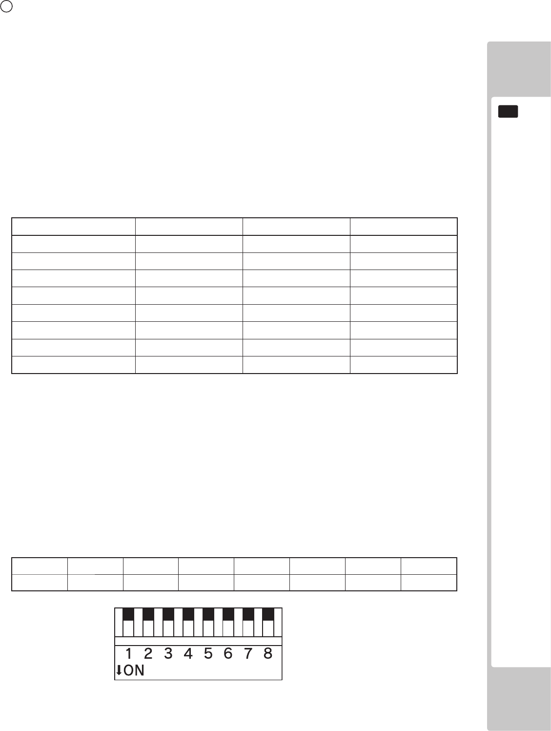
GAME BOARD
115
16
4 DIP SW
No. 1, No. 2 and No.3:
Use differs depending on game software. Set according to the Service Manual provided with the game software itself.
No. 4:
Changes the facing of the monitor. Use differs depending on game software. Set according to the Service Manual provided
with the game software itself. If no specic directions are given set to horizontal display (OFF).
OFF: Horizontal display
ON: Vertical display
No. 5, No. 6 and No. 7:
Set the resolution of the video output.
Use differs depending on game software. Set according to the Service Manual provided with the game software itself.
No. 1 No. 2 No. 3 No. 4 No. 5 No. 6 No. 7 No. 8
OFF OFF OFF OFF OFF OFF OFF OFF
Resolution No. 5 No. 6 No. 7
*OFF OFF OFF
640 x 480 ON OFF OFF
1024 x 600 OFF ON OFF
1024 x 768 ON ON OFF
1280 x 720 OFF OFF ON
1280 x 1024 ON OFF ON
1360 x 768 OFF ON ON
1920 x 1080 ON ON ON
For SONIC & SEGA ALL-STARS RACING ARCADE the resolution is 1280x720
No. 8:
Use differs depending on game software. Set according to the Service Manual provided with the game software itself.
The diagram below shows all 8 switches in the OFF position.

116
GAME BOARD
16
16-3 RINGWIDE COMPONENTS
■ ACCESSORIES
Parts not labeled with part numbers are as yet unregistered or cannot be registered. Be sure to handle all parts with care, as
some parts are not available for purchase separately.
DESCRIPTION/PART NO. FIGURES/NOTES QTY
TAPPING SCREW
011-P00412
4
Used for installing the RINGWIDE.
RINGWIDE
847-0001D-01 : USA
847-0001D-02 : OTHERS
847-0001D-03 : CHINA
1 ea.
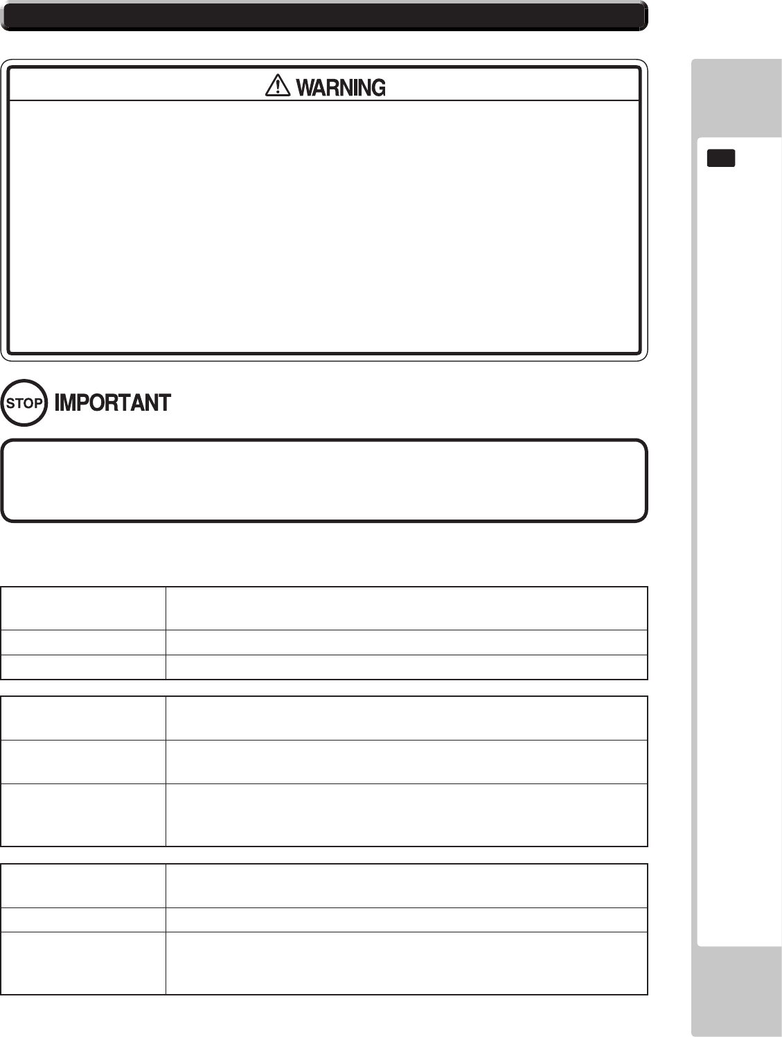
GAME BOARD
117
16
DISPLAY Error 0001
Keychip Not Found
CAUSE There is no key chip, or the key chip is not connected correctly.
COUNTERMEASURES Check that the key chip is connected correctly.
DISPLAY Error 0002
Keychip Not Available
CAUSE The key chip is not supported. The RINGWIDE system program must be
updated.
COUNTERMEASURES Check how the game was installed.
If that doesn’t x the problem, contact the ofce listed in this manual or the
point of purchase for this product.
DISPLAY Error 0004
Game Program Not Acceptable
CAUSE The key chip is not supported.
COUNTERMEASURES Check that the key chip from a different system is not inserted.
If that doesn’t x the problem, contact the ofce listed in this manual or the
point of purchase for this product.
● If an error code is displayed get on-site maintenance personnel or other
qualied professional to look at it. An unqualied person attempting to resolve
an error code problem may lead to electric shock, short circuit and risk of re.
If no on-site maintenance personnel or qualied professional is available
immediately turn off the power and contact the customer services in this
manual or your supplier.
● If a problem not described in this manual occurs, or the resolution to a problem
described in this manual is not effective, do not make further attempts to
resolve the problem yourself. Immediately turn off the power and contact the
ofce listed in this manual or your supplier. Any unguided attempts to solve
such problems may lead to a serious accident.
If an error number or message not listed below appears, cease using the product
immediately and contact the ofce listed in this manual or the point of purchase
for this product.
RINGWIDE is equipped to display various errors on-screen to help solve any problems. If an error is displayed the game
cannot be used. Use the following table of causes and countermeasures to solve the problem.
16-4 ERROR CODE DISPLAY
118
GAME BOARD
16
DISPLAY Error 0008
Keychip Access Failed
CAUSE The key chip could not be accessed.
COUNTERMEASURES Reinsert the key chip and restart RINGWIDE.
If that doesn’t x the problem, contact the ofce listed in this manual or the
point of purchase for this product.
DISPLAY Error 0010
Unexpected Game Program Failure
CAUSE The game program crashed due to an unexpected error.
COUNTERMEASURES Turn the power off and then restart the RINGWIDE.
If that doesn’t x the problem, contact the ofce listed in this manual or the
point of purchase for this product.
DISPLAY Error 0020
EXIO Not Found
CAUSE The I/O board inside RINGWIDE is not recognized.
COUNTERMEASURES Turn the power off and then restart the RINGWIDE.
If that doesn’t x the problem, contact the ofce listed in this manual or the
point of purchase for this product.
DISPLAY Error 0021
Main board Malfunctioning
CAUSE The main board does not recognize itself.
COUNTERMEASURES Contact the ofce listed in this manual or the point of purchase for this
product.
DISPLAY Error 0022
Game Program Not Found on Storage Device
CAUSE There is no game program on the storage device.
COUNTERMEASURES Use the installation media (DVD DRIVE, etc.) to reinstall the game.
DISPLAY Error 0023 - 0026
Main board Malfunctioning
CAUSE Failed to access the main board.
COUNTERMEASURES Turn the power off and then restart the RINGWIDE.
If that doesn’t x the problem, contact the ofce listed in this manual or the
point of purchase for this product.
DISPLAY Error 0027
Low Battery
CAUSE The button battery may be depleted.
COUNTERMEASURES Replace the button battery.
DISPLAY Error 0041
Game Program Not Found on Install Media
CAUSE There is no game program on the install media.
COUNTERMEASURES Check that the game program, place on the install media (DVD DRIVE
etc.), and the key chip correspond to each other.
GAME BOARD
119
16
DISPLAY Error 0042
Game Program Not Found on Install Media
CAUSE Some part of the game program is missing.
COUNTERMEASURES Check how the game was installed.
If that doesn’t x the problem, contact the ofce listed in this manual or the
point of purchase for this product.
DISPLAY Error 0049
Install Media Access Failed
CAUSE Failed to access the install media.
COUNTERMEASURES Check that the install media (DVD DRIVE etc.) is connected correctly.
Check that the game disk is not scratched, damaged or dirty.
If that doesn’t x the problem, contact the ofce listed in this manual or the
point of purchase for this product.
DISPLAY Error 0052
Install Media Access Failed
CAUSE Failed to access the install media.
COUNTERMEASURES Check that the install media (DVD DRIVE etc.) is connected correctly.
Check that the game disk is not scratched, damaged or dirty.
If that doesn’t x the problem, contact the ofce listed in this manual or the
point of purchase for this product.
DISPLAY Error 0055
Game Program Verify Error
CAUSE The installed game program is not working correctly.
COUNTERMEASURES Turn the power off and then restart the RINGWIDE.
If that doesn’t x the problem, contact the ofce listed in this manual or the
point of purchase for this product.
DISPLAY Error 0064
Game Program Not Found on Server
CAUSE No game program on the LAN install server.
COUNTERMEASURES Check that the game program, place on the LAN install server, and the key
chip correspond to each other.
DISPLAY Error 0066
Game Program Verify Error
CAUSE The installed game program is not working correctly.
COUNTERMEASURES Turn the power off and then restart the RINGWIDE.
If that doesn’t x the problem, contact the ofce listed in this manual or the
point of purchase for this product.
DISPLAY Error 0081
Invalid Storage Format
CAUSE The storage format is wrong.
COUNTERMEASURES Contact the ofce listed in this manual or the point of purchase for this
product.
120
GAME BOARD
16
DISPLAY Error 0082
Game Program Access Failed
CAUSE The storage device cannot be recognized.
COUNTERMEASURES Reinstall the game program.
If that doesn’t x the problem, contact the ofce listed in this manual or the
point of purchase for this product.
DISPLAY Error 0083
Storage Device Not Acceptable
CAUSE The storage does not have enough space.
COUNTERMEASURES Contact the ofce listed in this manual or the point of purchase for this
product.
DISPLAY Error 0084
Storage Device Malfunctioning
CAUSE The storage device may be broken.
COUNTERMEASURES Turn the power off and then restart the RINGWIDE.
If that doesn’t x the problem, contact the ofce listed in this manual or the
point of purchase for this product.
DISPLAY Error 0085
Invalid Storage Format
CAUSE The storage format is wrong.
COUNTERMEASURES Contact the ofce listed in this manual or the point of purchase for this
product.
DISPLAY Error 0088
System Program Verify Error
CAUSE The installed system program is not working correctly.
COUNTERMEASURES Perform a manual recovery of RINGWIDE.
If that doesn’t x the problem, contact the ofce listed in this manual or the
point of purchase for this product.
DISPLAY Error 0090
High CPU Temperature
CAUSE The CPU temperature is high.
COUNTERMEASURES Refer to Chapter 7, and clean RINGWIDE.
If that doesn’t x the problem, contact the ofce listed in this manual or the
point of purchase for this product.
DISPLAY Error 0091
Too High CPU Temperature
CAUSE The CPU temperature is high.
COUNTERMEASURES Refer to Chapter 7, and clean RINGWIDE.
If that doesn’t x the problem, contact the ofce listed in this manual or the
point of purchase for this product.
DISPLAY Error 0501 - 0530
(No message)
CAUSE The connected device cannot be recognized.
COUNTERMEASURES Turn the power off and then restart the RINGWIDE.
If that doesn’t x the problem, contact the ofce listed in this manual or the
point of purchase for this product.
GAME BOARD
121
16
DISPLAY Error 0531
(No message)
CAUSE The connected graphics device cannot be recognized.
COUNTERMEASURES Turn the power off and then restart the RINGWIDE.
If that doesn’t x the problem, contact the ofce listed in this manual or the
point of purchase for this product.
DISPLAY Error 0532
(No message)
CAUSE The connected USB device cannot be recognized.
COUNTERMEASURES Check that the USB devices are connected correctly, and turn the power
off and then restart the RINGWIDE.
If that doesn’t x the problem, contact the ofce listed in this manual or the
point of purchase for this product.
DISPLAY Error 0533 - 0550
(No message)
CAUSE The connected device cannot be recognized.
COUNTERMEASURES Turn the power off and then restart the RINGWIDE.
If that doesn’t x the problem, contact the ofce listed in this manual or the
point of purchase for this product.
DISPLAY Error 0901
Wrong Platform
CAUSE The game board being used is not supported.
COUNTERMEASURES Check to see if any game programs have been upgraded.
DISPLAY Error 0902
Wrong System Program
CAUSE It was started up with an unsupported system program.
The RINGWIDE system program must be updated.
COUNTERMEASURES Check how the game was installed.
If that doesn’t x the problem, contact the ofce listed in this manual or the
point of purchase for this product.
DISPLAY Error 0903
Wrong Region.
CAUSE The game is for a foreign region.
COUNTERMEASURES Use a domestic game.
DISPLAY Error 0905
Graphic Function Not Found
CAUSE The RINGWIDE graphics function cannot be recognized.
COUNTERMEASURES Check that the game program is compatible with the RINGWIDE.
If it is, contact the ofce listed in this manual or the point of purchase for this
product.
122
GAME BOARD
16
DISPLAY Error 0906
Sound Function Not found
CAUSE The RINGWIDE sound function cannot be recognized.
COUNTERMEASURES Contact the ofce listed in this manual or the point of purchase for this
product.
DISPLAY Error 0907
Not Enough System Memory
CAUSE RINGWIDE does not have enough memory.
COUNTERMEASURES Contact the ofce listed in this manual or the point of purchase for this
product.
DISPLAY Error 0908
Not Enough SRAM
CAUSE RINGWIDE does not have enough SRAM.
COUNTERMEASURES Contact the ofce listed in this manual or the point of purchase for this
product.
DISPLAY Error 0909
Not Enough Storage Device
CAUSE RINGWIDE does not have enough storage.
COUNTERMEASURES Contact the ofce listed in this manual or the point of purchase for this
product.
DISPLAY Error 0910
Wrong Resolution Setting
CAUSE The game does not support the current resolution settings.
COUNTERMEASURES Change the DIP SW to the correct settings and restart the RINGWIDE.
DISPLAY Error 0911
Wrong Horizontal/Vertical Setting.
CAUSE The monitor horizontal/vertical settings are incorrect.
COUNTERMEASURES Change the DIP SW to the correct settings and restart the RINGWIDE.
DISPLAY Error 0949
Keychip Not Found
CAUSE Failed to access the key chip.
COUNTERMEASURES Check that the key chip is connected correctly.
DISPLAY Error 6401
JVS I/O board is not connected to main board.
CAUSE (1) The I/O board is not connected.
(2) Unreliable connection between the game board and the I/O board.
COUNTERMEASURES (1) Connect the I/O board to RINGWIDE.
Check that the power cable is connected to I/O board.
(2) Reconnect or replace the JVS cable that connects the I/O board to
RINGWIDE.
DISPLAY Error 6402
JVS I/O board does not fulll the game spec.
CAUSE The correct I/O board is not connected.
COUNTERMEASURES Use an I/O board that provides the proper input/output for the game.
GAME BOARD
123
16
DISPLAY Error 8001
Network address error (DHCP)
CAUSE The network connection settings could not be initialized.
COUNTERMEASURES Check the network connection and follow the startup procedures to restart
the system.
DISPLAY Error 8002
Network setting error (SYSTEM)
CAUSE The SYSTEM TEST MODE NETWORK SETTING is incorrect.
COUNTERMEASURES Check the NETWORK SETTING.
DISPLAY Error 8003
Network address error (Dup.IP)
CAUSE The network connection settings could not be initialized.
COUNTERMEASURES Check the network connection and follow the startup procedures to restart
the system.
DISPLAY Error 8004
Network setting error (Dup.IP)
CAUSE The SYSTEM TEST MODE NETWORK SETTING is incorrect.
COUNTERMEASURES Check the NETWORK SETTING.
DISPLAY Error 8005
Network type error (WAN)
CAUSE The line type of the connected ALL.Net router is incorrect.
COUNTERMEASURES Check the line type of the connected ALL.Net router.
DISPLAY Error 8006
Network timeout error (DHCP)
CAUSE The network connection settings could not be initialized.
COUNTERMEASURES Check the network connection and follow the startup procedures to restart
the system.
DISPLAY Error 8007
Network timeout error (DNS-WAN)
CAUSE A connection could not be established with ALL.Net.
COUNTERMEASURES Check the RINGWIDE network connection, the in-store network connection
and the connection between the ALL.Net router and the network cable,
and then follow the startup procedures to restart the system.
If the error persists, check the maintenance information.
DISPLAY Error 8008
Network timeout error (DNS-LAN)
CAUSE A connection could not be established with the ALL.Net router.
COUNTERMEASURES Check the RINGWIDE network connection and the in-store network ALL.Net
connection and then follow the startup procedures to restart the system.
DISPLAY Error 8009
Network Game Disabled
CAUSE The GAME TEST MODE ALL.Net connection is set to OFF.
COUNTERMEASURES Check the GAME TEST MODE settings.
124
GAME BOARD
16
DISPLAY Error 8103
ALL.Net System error (TIMEOUT)
CAUSE A connection could not be established with ALL.Net.
COUNTERMEASURES Check the RINGWIDE network connection, the in-store network connection
and the connection between the ALL.Net router and the network cable,
and then follow the startup procedures to restart the system.
If the error persists, check the maintenance information.
DISPLAY Error 8104
ALL.Net System error (REG)
CAUSE ALL.Net registration could not be conrmed.
COUNTERMEASURES Check to make sure ALL.Net registration (the agreement) has been
successfully completed.
DISPLAY Error 8106
ALL.Net System Caution
CAUSE A connection could not be established with ALL.Net.
COUNTERMEASURES Check the RINGWIDE network connection, the in-store network connection
and the connection between the ALL.Net router and network cable, and
then follow the startup procedures to restart the system.
If the error persists, check the maintenance information.
DISPLAY Error 8111
ALL.Net System error (REG)
CAUSE ALL.Net registration could not be conrmed.
COUNTERMEASURES Check to make sure ALL.Net registration (the agreement) has been
successfully completed.
DISPLAY Error 8113
ALL.Net System error (MODE)
CAUSE The ALL.Net settings could not be conrmed.
COUNTERMEASURES Contact the ofce listed in this manual.
DISPLAY Error 8114
ALL.Net System error (RTC)
CAUSE A connection could not be established with ALL.Net.
COUNTERMEASURES Check the RINGWIDE network connection, the in-store network connection
and the connection between the ALL.Net router and the network cable,
and then follow the startup procedures to restart the system.
If the error persists, check the maintenance information.
DISPLAY Error 8201
ALL.Net System error (TIMEOUT)
CAUSE A connection could not be established with ALL.Net.
COUNTERMEASURES Check the RINGWIDE network connection, the in-store network connection
and the connection between the ALL.Net router and network cable, and
then follow the startup procedures to restart the system.
If the error persists, check the maintenance information.
GAME BOARD
125
16
DISPLAY Error 8202
ALL.Net System error (REG)
CAUSE ALL.Net registration could not be conrmed.
COUNTERMEASURES Check to make sure ALL.Net registration (the agreement) has been
successfully completed.
DISPLAY Error 8301
Network error (GAME-LAN)
CAUSE The connection with the devices that make up this game could not be
conrmed.
COUNTERMEASURES Check the network connection and follow the startup procedures to restart
the system.
DISPLAY Error 8302
Maintenance time (GAME)
CAUSE Currently the server is undergoing maintenance.
COUNTERMEASURES Wait until server maintenance is complete.
DISPLAY Error 8303
Network error (GAME)
CAUSE A connection could not be established with ALL.Net.
COUNTERMEASURES Check the RINGWIDE network connection, the in-store network connection
and the connection between the ALL.Net router and the network cable,
and then follow the startup procedures to restart the system.
If the error persists, check the maintenance information.
DISPLAY Error 8304
Network failed (GAME)
CAUSE Automatic recovery from the network failure is not possible.
COUNTERMEASURES Check the RINGWIDE network connection, the in-store network connection
and the connection between the ALL.Net router and the network cable,
and then follow the startup procedures to restart the system.
If the error persists, check the maintenance information.
126
GAME BOARD
16
DISPLAY Error 1000
Force Feedback Error
CAUSE Failed to initialise motor controller during power on cycle.
COUNTERMEASURES Check all connection to and from Motor Controller.
Possible failure of Motor Controller PCB. Replace and restart.
DISPLAY <TICKET ERROR> PLEASE CONTACT OPERATOR
CAUSE Ticket has jammed or tickets are empty.
COUNTERMEASURES Clear ticket jam. Reoat with new tickets.
Note: When resetting the error message, please take note of the number of
tickets owed to the player as this number of tickets cannot be recalled.
DISPLAY ,<NETWORK FAILURE> PLEASE CONTACT OPERATOR
CAUSE Communication failure across the network.
COUNTERMEASURES Check all network cables for damage. Check all network connections to
Hub. Check Hub for power. Possible Hub failure.
DISPLAY <NETWORK FAILURE> <CABINET ID CONFLICT> PLEASE CONTACT OPERATOR
CAUSE Incorrect values given to individual cabinets across the network.
COUNTERMEASRES See chapter 9-3-4 on setting cabinet identications
Other ERROR codes.
GAME BOARD
127
16
ManualRecovery
Use the following procedure to return the RINGWIDE system software to a previous state.
1 Press the TEST and SERVICE Buttons simultaneously with the RINGWIDE power off.
Hold the buttons down and turn on the power.
2 After RINGWIDE starts up and the following message is displayed, release the buttons.
The system software will recover automatically. The Advertising screen will be displayed once
everything nishes. Until it is displayed, do not interfere with the cabinet’s operations.
(If you are uninstalling a game, the Install Wait screen will be displayed.)
SYSTEM UPDATE
STEP1
DO NOT TURN OFF THE POWER
128
GAME BOARD
16
● Make sure you do not damage the printed board and wires. Such damage can
lead to electric shock, short circuit and re hazard.
● To prevent overheating, explosion, or re:
- Do not recharge, disassemble, heat, incinerate, or short the battery.
- Do not allow the battery to come into direct contact with metallic objects or
other batteries.
- To preserve the battery, wrap it in tape or other insulating material.
● Follow local regulations when disposing of the battery. Improper disposal can
damage the environment.
● Even the site maintenance personnel or other qualied professionals must not
perform replacement operations for parts not described in this manual. In the
event that such work is required either contact the ofce listed in this manual or
rst conrm the procedure with the place or ofce of purchase. Failure to do so
may lead to electric shock or short circuit.
● Do not turn on the power with current carrying parts exposed. Doing so could
result in electric shock or short circuit.
● The batteries in RINGWIDE can be used for approximately 4 years of standard
usage. If the battery appears to require replacement sooner than 4 years it is
more likely that an error has occurred with some other part of the board. Rather
than exchanging the battery requesting repair of the board itself may be more
appropriate.
● Static electricity from your body may damage some electronics devices on the
IC board. Before handling the IC board, touch a grounded metallic surface so
that the static electricity can be discharged.
To avoid risk of malfunction and damage:
- Make sure the positive and negative ends are aligned correctly.
- Use only batteries approved for use with this unit.
16-5 REPLACING THE BUTTON BATTERY
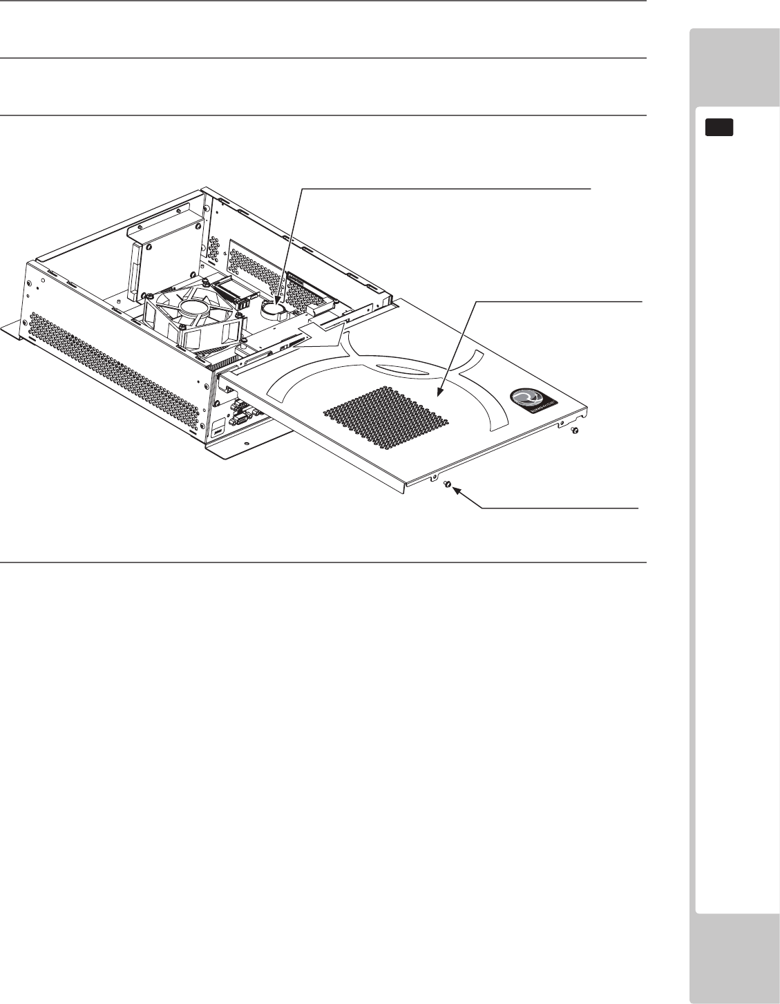
GAME BOARD
129
16
4 The main board is the board on the bottom of the RINGWIDE shield case.
After replacing the main board’s button battery, refer to Step 3 and close the lid.
The button battery that require replacement can be found on the main board, inside the RINGWIDE shield case.
1 Remove the unit on which RINGWIDE is placed from the game cabinet.
RINGWIDE must be removed still attached to the base (wooden shelf, etc.).
2 Remove 2 screws for the RINGWIDE lid. The screws are on top of the connector side.
3 Slide the lid toward the side with the connectors, and remove it.
401-0070
BUTTON BATTERY (BATTERY LITHIUM CR2032 SONY)
SCREW (2)
M3 x 6, w/at & spring washers
Slide toward the connectors side.
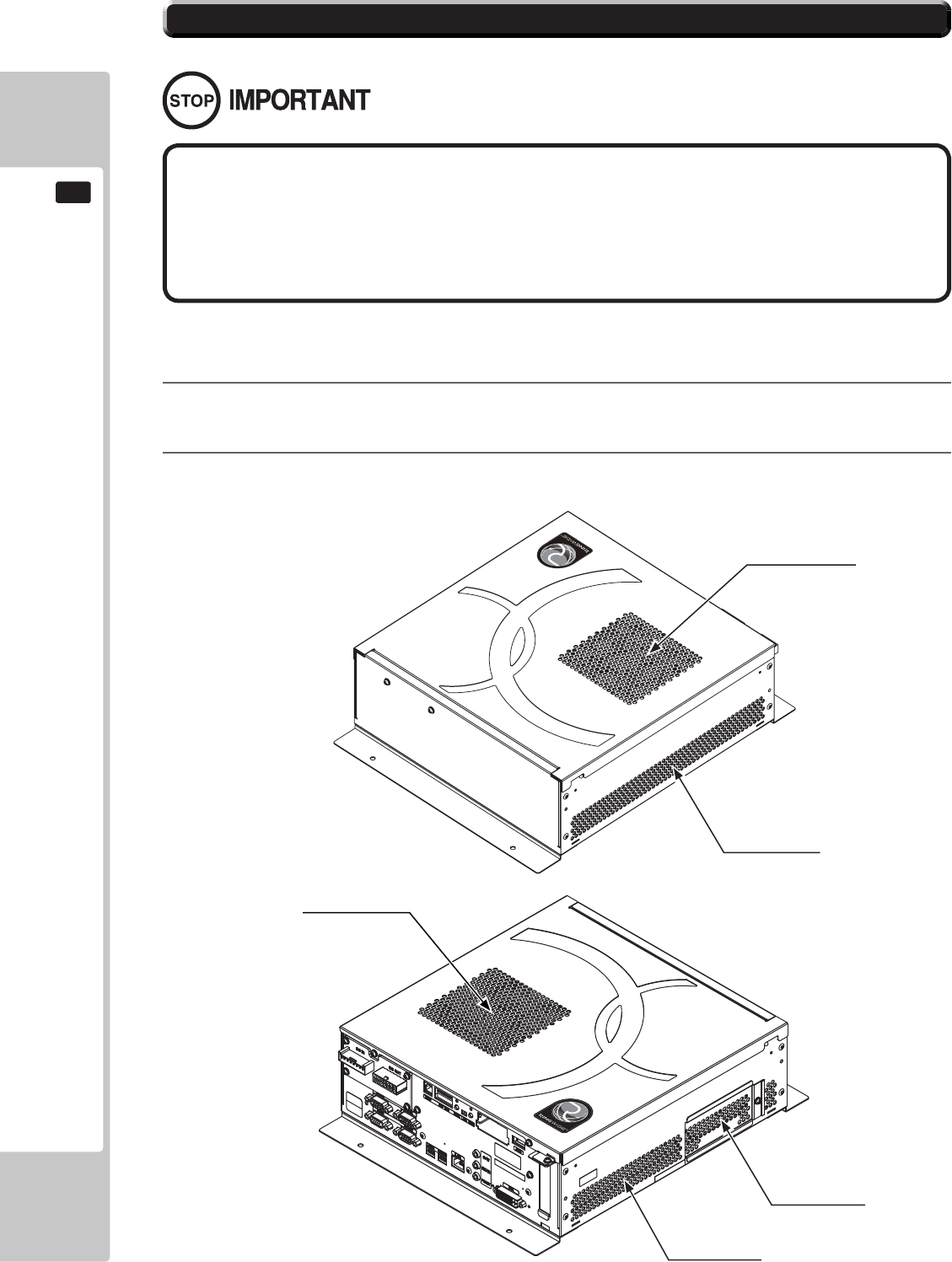
130
GAME BOARD
16
1 Refer to the manual included with the game machine, and remove RINGWIDE from the cabinet.
2 Clean around the intake/exhaust vents of RINGWIDE with a vacuum cleaner.
● Clean RINGWIDE once a year or whenever either “Error 0090” or “Error 0091”
occurs. Dust accumulating in game boards may not function properly.
● Set each cabinet to correct settings after cleaning the product. Be sure to set
RINGWIDE to correct settings when returning. If the proper settings are not used,
the units may not function properly.
Once a year remove RINGWIDE from the cabinet and use a vacuum cleaner to clean around the RINGWIDE’s air vents and
installation area.
EXHAUST VENT
INTAKE VENT
EXHAUST VENT
INTAKE VENT
INTAKE VENT
16-6 CLEANING RINGWIDE

GAME BOARD
131
16
3 Clean around installment parts of RINGWIDE in the cabinet with a vacuum cleaner.
Be sure not to damage wirings and boards. Electronic devices on boards may damage by
static electricity,
and be sure not to vacuum electronic devices by a vacuum cleaner.
4 Set each RINGWIDE you removed by the reverse method.
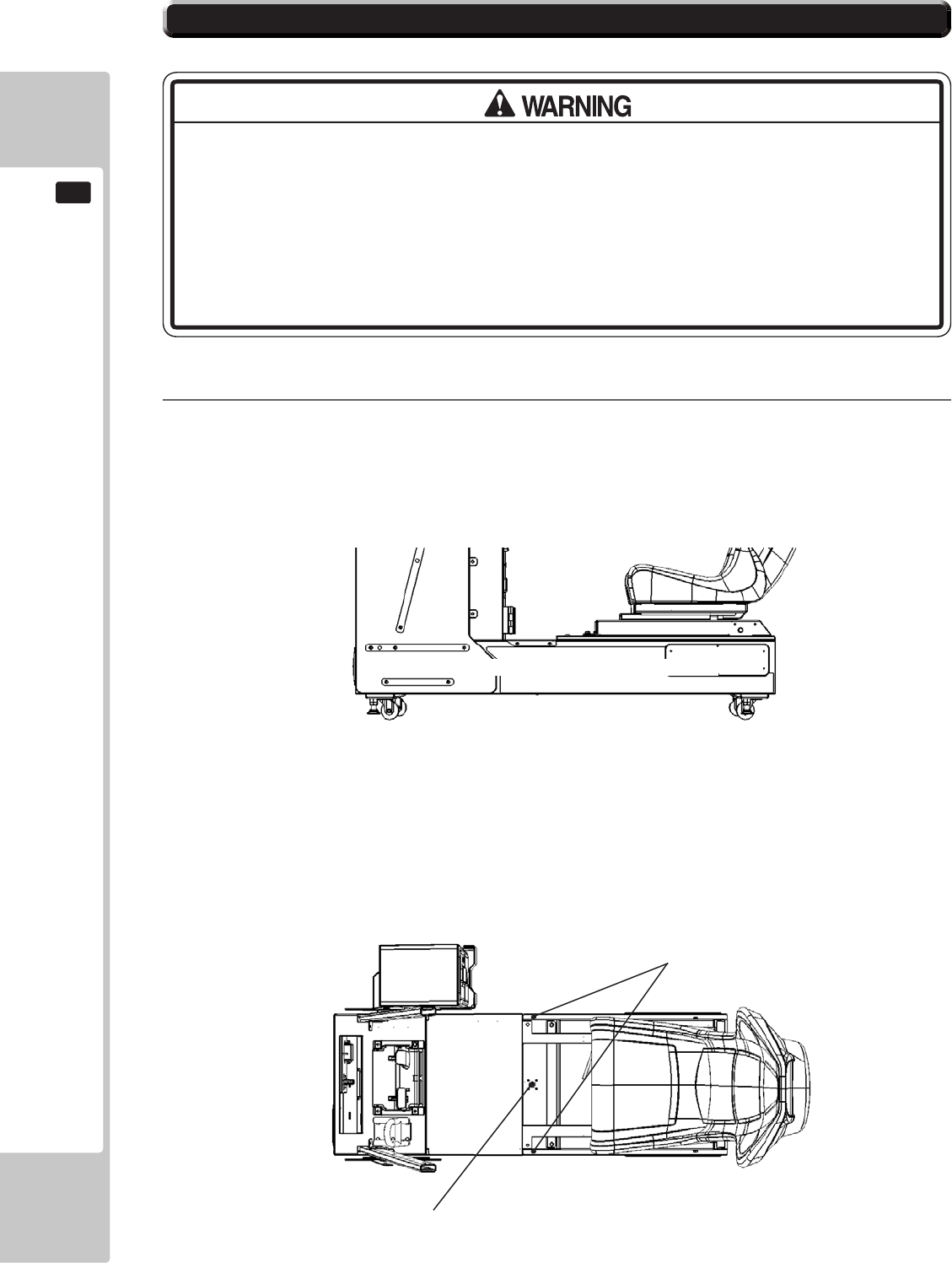
132
GAME BOARD
16
16-7 GAME BOARD (RINGWIDE) - LOCATION
1
The machine is tted with a Ringwide Game Board and several other Ancilliary Boards which are mainly
housed inside the Base Box. Only qualied Personnel should attempt to Service these Units.
● When returning the game board after making repairs or replacements,
make sure that there are no errors in the connection of connectors. Erroneous
connections can lead to electrical shock, short circuits or res.
● When connecting a connector, check the direction carefully. Connectors must
be connected in only one direction. If indiscriminate loads are applied in making
connections, the connector or its terminal xtures could be damaged, resulting in
electrical shock, short circuits or res.
The Game Board Unit is located under the Player Seat, and to gain access the following procedure should be
carried out.
Unlock the Seat Lid and then remove the M6x16 Hex Bolt located on each edge of the Lid.
Control PCB's located inside Base Box
M6 Hex Bolt (2)
Lock (J9117)
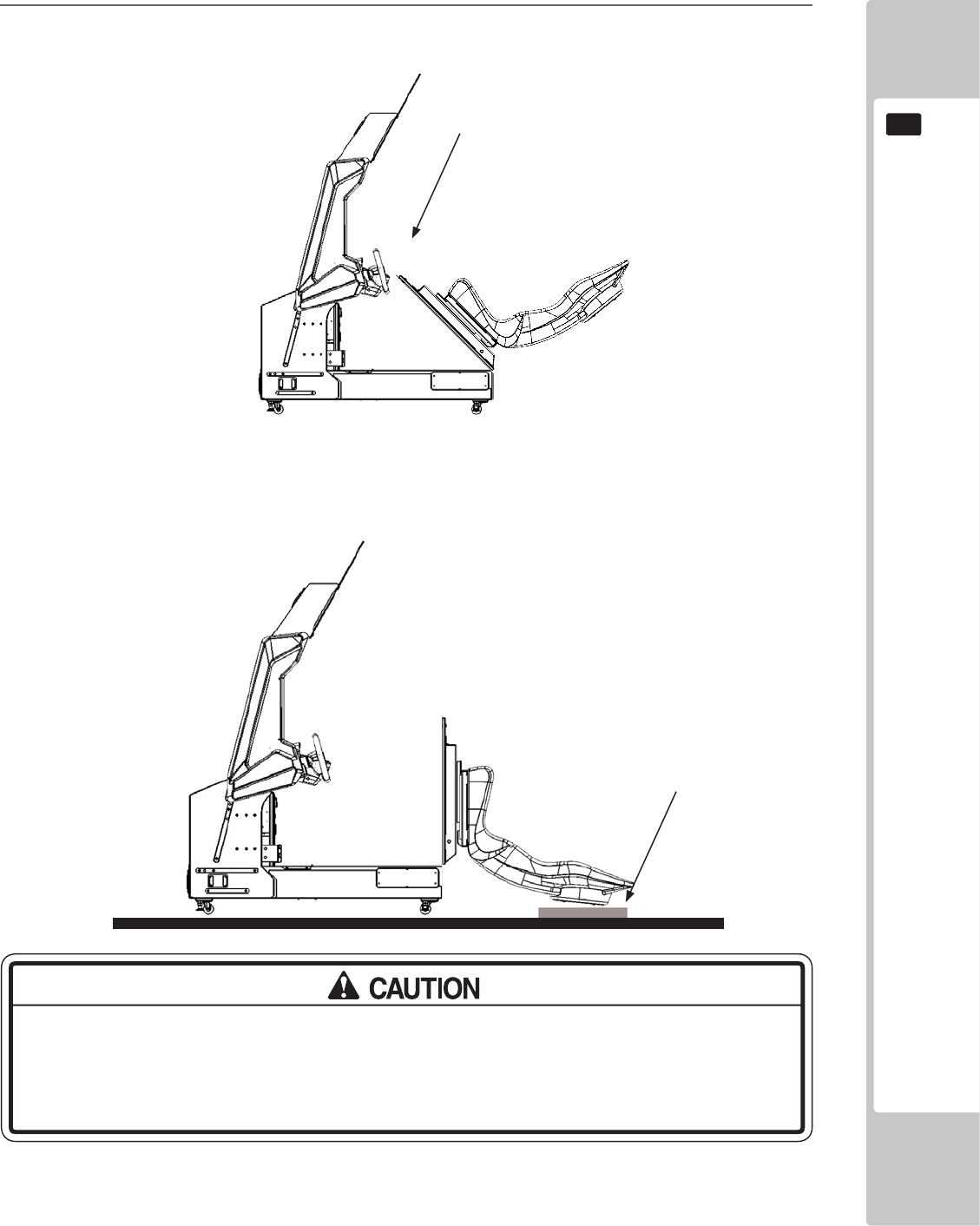
GAME BOARD
133
16
Cushion
GREAT CARE SHOULD BE TAKEN WHEN OPENING AND CLOSING THIS UNIT.
LIKELY CHANCE OF MACHINE DAMAGE OR PERSONNEL INJURY IF UNIT IS DROPPED
DURING OPENING AND CLOSING.
2
Once released, the Seat Lid may be opened by tilting it backwards.
Due to the weight of the unit, great care should be taken when opening the Seat Lid, if dropped Impact
Damage is likely to occur.
Before opening the unit, a protective cushion or padding should be placed on the ground in the approximate
position where the seat back will touch the oor. This is to help prevent the back of the seat from getting
scratched and marked and when opening, the back of the seat should be carefully lowered to the oor,
placing it on the protective cushion.
Tilt
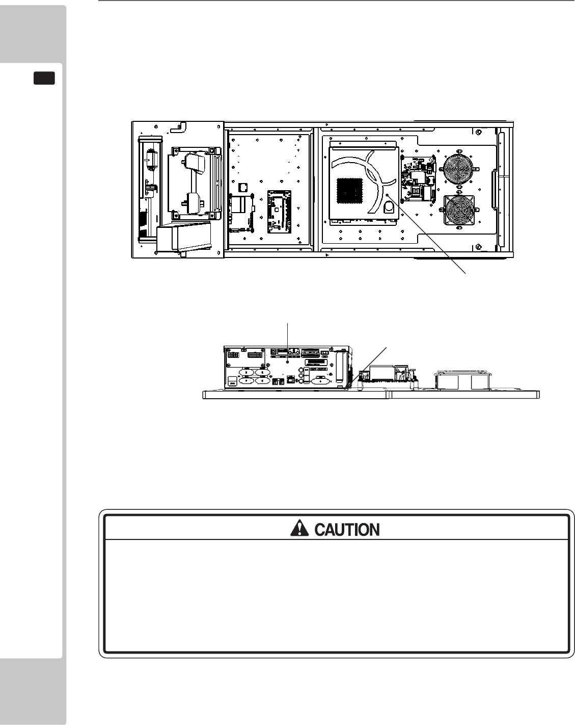
134
GAME BOARD
16
Game Board
Fixing Points
Do not open the Game Board without the express permission of SEGA. If for any
reason entry has been gained into the Game Board without the permission of
SEGA, then all warranty rights become void.
When returning the Game Board to SEGA for service, then please make sure that
adequate packaging is used as damage in transit make occur.
Game Board
3
The Assy Game Board is located to the rear of the cabinet. The Game Board can be removed from this
assembly by removing the (4) xings which retain it to the wooden base.
COMMUNICATION PLAY
17
135
17-1 INSTALLATION PRECAUTIONS
• To perform work safely, be sure to secure the space corresponding to number
of machines to be linked. Failure to observe this can cause accident.
• To avoid accidents, use a cable cover that will not cause patrons to trip when
laying network cables in areas of heavy foot trafc.
• To prevent accidents and acts of vandalism, cover the network cables with the
strongest cover possible.
• Before starting to work, ensure that the Power SW is OFF. Failure to observe this
can cause electric shock or short circuit.
• Use care so as not to damage wirings. Damaged wiring can cause electric
shock or short circuit.
• Do not touch undesignated places. Touching places not designated can cause
electric shock or short circuit.
• The work described below should be carried out by the site maintenance
personnel or other qualied professional. Work carried out by personnel without
the necessary skill or technology can cause accident.
• To perform work safely and avoid serious accident such as the cabinet falling
down, do not perform work in places where step-like grade differences, a ditch,
or slope exist.
• To prevent accidents while working or while operating the product after it
has been installed, be sure not to conduct any procedures other than those
given in this manual. There are cases in which procedures not covered in this
manual require special tools and skills. If a procedure not given in this manual is
required, request service from the ofce given in this manual or from the point of
purchase.
For this game, up to 8 machines can be networked together allowing up to 8 players to play simultaneously. In
this instance, connecting the communication cable and adjustment to the settings for communication play will be
required.
Since 2 or more machines are to be linked, sufcient power corresponding to the number of machines used need to
be supplied. Note that as a standard, the per machine capacity should be 14A for the 100-120V area, and 6A for the
220-240V area.
17 COMMUNICATION PLAY
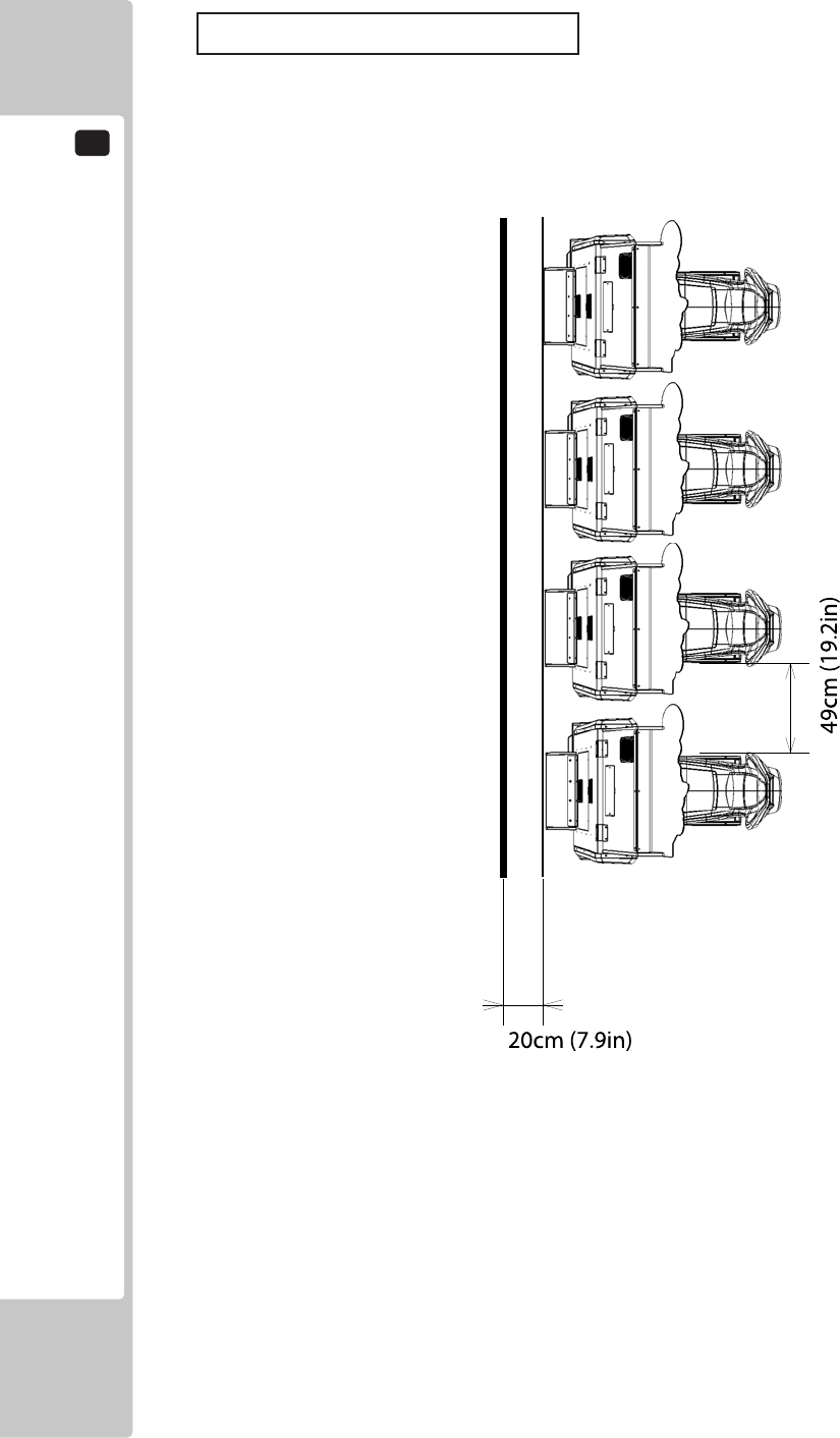
17
COMMUNICATION PLAY
136
Distance between Machines
The maximum distance between the game machines depends on the length of the cables connecting them, but make
sure the units are separated from each other by at least 49 cm (19.2 in) so that players can pass between them.
17-1 Fig 01
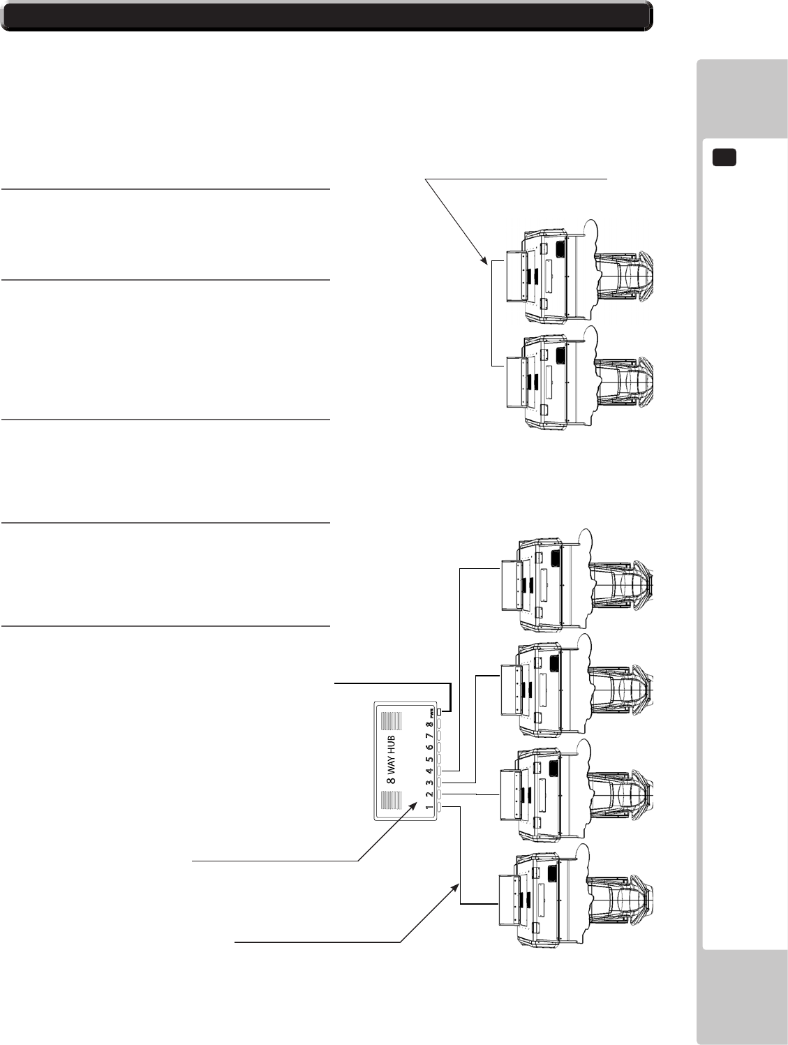
COMMUNICATION PLAY
17
137
To enable network play, the Hubs inside each of the game machines involved must be connected with network (LAN)
cables. Up to a maximum of 8 machines (8 Players) can be Networked together, all that's required is to connect an
an external Hub (supplied seperately) between each of the machines that are to complete the ‘Network’.
Do not connect LAN cables to game machines when they are not used for network play.
17-2 CONNECTING THE COMMUNICATION CABLE
1
Turn off the power and unplug the power cord
from the outlet.
2
Using Chapter 6 of this manual as reference, move
the machines so that they are lined up.
Leave enough space behind each Unit to allow
access for a Network HUB (only required for 3 or
more seats) which when located will be positioned
near the Master Machine.
3
When linking 2 machines a connection can be
made directly from machine to machine using the
Lan connection point housed within the AC Unit.
Connect the two machine using the Lan Cable
(Supplied).
4
When linking 3 or more seats a Hub Kit must
be used. Please contact SEGA or your local
distributors office for further technical or sales
information
5
Once the desired Network connections have been
established, power on the machines and enter
TEST MODE to allocate each seat a number
within the GAME ASSIGNMENTS.
A typical illustration of 4 seats in a network
Network Kit - Not Supplied
Standard Lan Network Cable
(Connect the Lan cable (supplied) directly
between two cabinets to link a single pair).
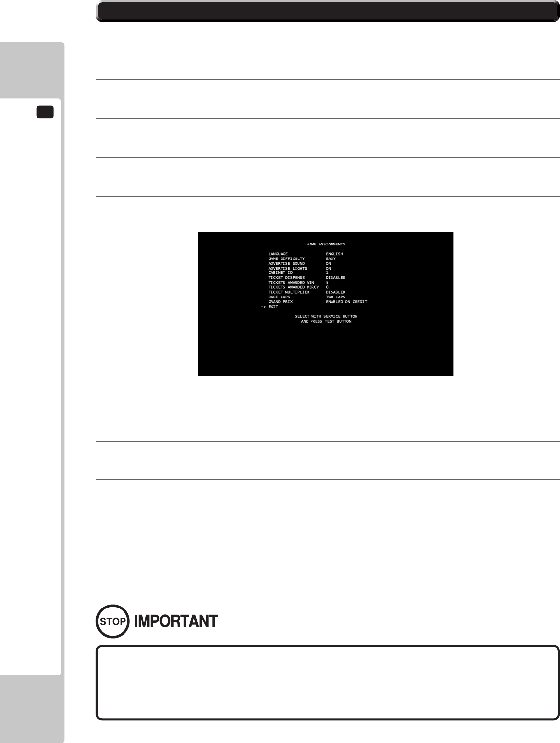
17
COMMUNICATION PLAY
138
• ONLY USE STANDARD LAN OR NETWORK CABLES FOR COMMUNICATION PLAY.
DO NOT USE NETWORK CROSSOVER CABLES AS THESE MAY CAUSE DAMAGE TO
THE GAME BOARD OR HUB.
17-3 NETWORK PLAY SETTINGS
Each of the linked machines must be set up for network play. If the machines are not set up correctly, network play
will not be possible.
For this game, up to 8 machines can be connected to allow up to 8 players to play simultaneously.
1
Turn on the power on each machine to be used in network play.
2
Initiate TEST MODE on ALL machines.
3
Select the GAME TEST MODE and press the Test button to display the GAME TEST MENU screen.
4
Select the GAME ASSIGNMENTS in the GAME TEST MENU screen and press the Test button.
5
Perform the CABINET ID setting. Set the different ID number to each machine. Be sure to assign one of
them with the ID number of “1”
6
Cause all of the machines to exit from the TEST MODE. Always select EXIT in the SYSTEM TEST
MENU screen.
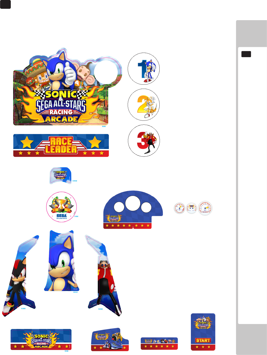
DESIGN - RELATED PARTS
139
18
For the warning display stickers, refer to Section 1.
18 DESIGN-RELATED PARTS
SSR-0507UK - BILLBOARD PLATE
SSR-1356UK - CENTRE PNL SPKR LEADER
SSR-0507-BUK - STKR INSERT #1
SSR-0507-CUK - STKR INSERT #2
SSR-0507-DUK - STKR INSERT #3
SSR-0507-EUK - STKR INSERT #4
SSR-0507-FUK - STKR INSERT #5
SSR-0507-GUK - STKR INSERT #6
SSR-0507-HUK - STKR INSERT #7
SSR-0507-HUK - STKR INSERT #8
SSR-1209UK - SIDE PANEL L SSR-1210UK - SIDE PANEL R
SSR-1651-CUK - STKT SEAT LWR
SSR-1505UK - STICKER MAIN BASE REAR
SSR-1654UK - WOOFER PLATE
SSR-1651-BUK - STKR SEAT UPPR
SSR-2001-BUK - METER PANEL
SSR-2001-BUK - METER PANEL
SSR-2001-BUK - METER PANEL
SSR-1654UK - WOOFER PLATE
SSR-1654UK - WOOFER PLATE
SSR-1654UK - WOOFER PLATE
SSR-1654UK - WOOFER PLATE
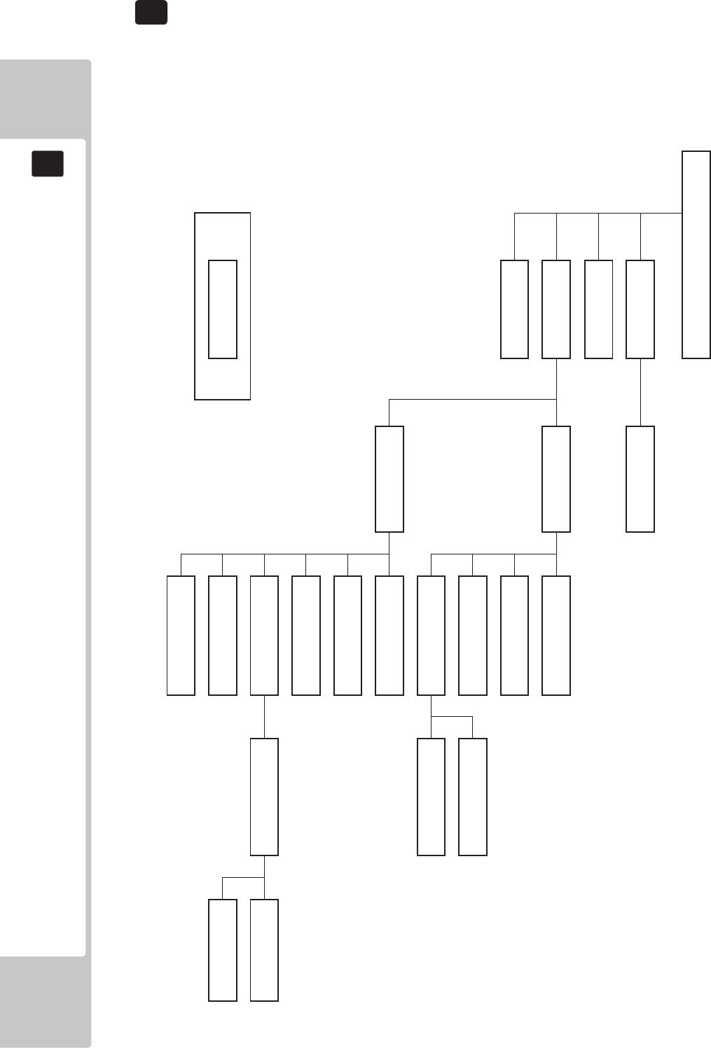
140
PARTS LIST
19
19 PARTS LIST
TOP ASSY SONIC SEGA RACING BOM
STRUCTURE
SSR-0000UK
TOP ASSY SONIC & SEGA ALL STAR RACING ARCADE
* ** *** **** *****
SSR-0300XUK SSR-0320UK
ASSY COIN CHUTE TWR ASSY SW UNIT DOUBLE METER
SSR-0500UK
ASSY BILLBOARD
SSR-1000UK SSR-1200UK SSR-1250UK
ASSY COCKPIT ASSY MONITOR CABI ASSY SUB MONITOR CABI
ST-1340UK RD-1280UK
ASSY 240V FAN ASSY LCD MONITOR
SSR-4700UK RD-1300UK SSR-2001UK
ASSY XMFR UK ASSY MONITOR MASK CONTROL PANEL COVER
SSR-2000UK SSR-2100UK
ASSY CONTROL PANEL ASSY SW PLATE
SSR-1500UK SSR-1520UK
ASSY MAIN BASE ASSY BASE BOX
SSR-1535UK
ASSY BASE LID R
SSR-1540UK
AC UNIT
SSR-1600UK SSR-1650UK SSR-1670UK
ASSY ADJUSTABLE SEAT ASSY SEAT LIT ASSY WOOFER
SSR-0700UK SSR-4500UK SSR-1680UK
ASSY TICKET VEND UNIT ASSY MAIN BD ASSY WOOFER LED
TICKET KIT SSR-4600UK
ASSY ELEC BD
ASSY TOP SONIC SEGA RACING STRUCTURE

141
PARTS LIST
19
1 ASSY TOP SONIC SEGA RACING (SSR-0002UK) (D-1/2)
ITEM NO PART NUMBER DESCRIPTION QTY
*1 SSR-0300XUK ASSY COIN CHUTE TOWER STD 1
*2 SSR-0500UK ASSY BILLBOARD 1
*3 SSR-1000UK ASSY COCKPIT 1
*4 RD-0001UK WIRE COVER 1
*5 RD-0004UK PLATE CCT BLANK 1
*6 421-7988-91UK STICKER SERIAL NUMBER UK 1
*7 ST-1340UK ASSY FAN 240VAC 1
*12 440-WS0100UK STICKER CAUTION FORK 2
*15 440-CS0186UK STICKER C EPILEPSY MULTI 1
*16 440-WS0030UK STICKER CAUTION 1
*17 440-WS0010UK STICKER DANGEROUS VOLTAGE 2
*18 LB1046 LABEL TESTED FOR ELEC. SAFETY 1
*19 RAL-XXXX-13UK LOCK COVER UK 1
*20 LB1130 LABEL WEEE WHEELIE BIN 1
*101 260-0024-01UK FAN AC AXIAL DP 200A 2
*102 FN1012 FAN GUARD METAL 120MM (FG-12) 2
*103 001195 RIVIT SNAP MOSS SR1811 8
*104 560-2410-03UK TRANSFORMER UK 240-100 3A (EU & ASIA ONLY) 1
*201 050-F00800 M8 NUT FLG 4
*203 068-852216 M8 WSHR 22OD FLT PAS 4
*204 000-P00408-WB M4X8 MSCR PAN W/FS BLK 2
*205 030-000625-SB M6X25 BLT W/S BLK 4
*206 068-652016-0B M6 WSHR 20OD FLT BLK 4
*209 000-P00412-W M4X12 MSCR PAN W/FS PAS 1
*210 060-F00400 M4 WSHR FORM A FLT PAS 1
*211 008-T00408-0C M4X8 TMP PRF TH CRM 4
*212 000-P00416-W M4X16 MSCR PAN W/FS PAS 12
*213 012-P00410-F N8X3/8" S/TAP FLF PAS 8
*215 068-441616 M4 WSHR 16OD FLT PAS 4
*301 600-7270-0200UK LAN CABLE X-OVER 200CM NOT 1
*302 ST-60026UK WH 240V FAN (NOT SHOWN) 2
*303 SSR-60001UK WH AC TO XFMR (NOT SHOWN) 1
*405 SSR-0507UK BILLBOARD PLATE 1
*406 SSR-0507-BUK STICKER BILLBOARD INSERT No1 (Sonic) 1
*407 SSR-0507-CUK STICKER BILLBOARD INSERT No2 (Tails) 1
*408 SSR-0507-DUK STICKER BILLBOARD INSERT No3 (Dr Eggman) 1
*410 LM1227 UK MAINS LEAD 10A WITH PLUG 1
*411 LM1246 EUROLEAD 10A EUROPEAN SOCKET 1
*412 420-0012-01UK MANUAL OSM SSR 1
*413 420-7210-01 MANUAL RINGWIDE
*415 PK0467 PALLET RD STD 1
*417 PK0469 BOX RD BILLBOARD 1
*418 SSR-0507-EUK STICKER BILLBOARD INSERT No4 1
*419 SSR-0507-FUK STICKER BILLBOARD INSERT No5 1
*420 SRS-0507-GUK STICKER BILLBOARD INSERT No6 1
*421 SSR-0507-HUK STICKER BILLBOARD INSERT No7 1
*422 SSR-0507-JUK STICKER BILLBOARD INSERT No8 1
*450 SSR-0507-08UK BILLBOARD PLATE CHN (CHINA EXPORT ONLY) 1
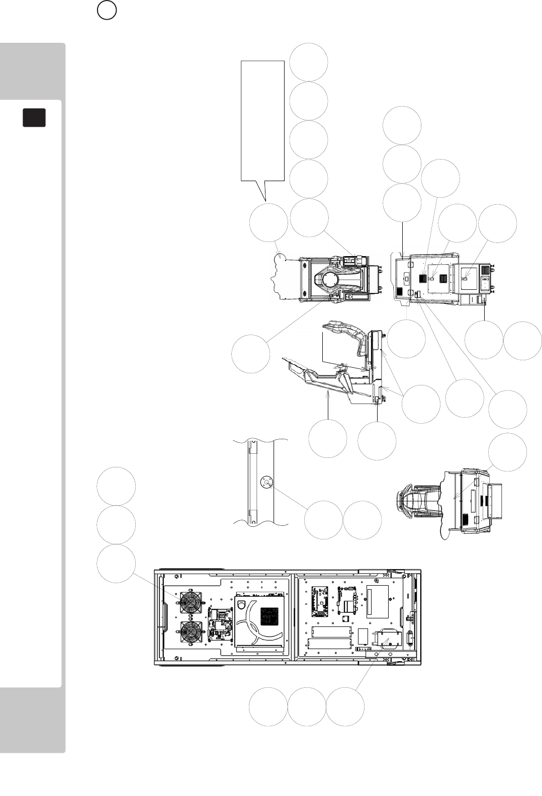
142
PARTS LIST
19
1 ASSY TOP SONIC SEGA RACING (SSR-0002UK) (D-2/2)
104213215
101
102
103
2
4
6
15
17
18
5
7
12
16
20
31
201 203
204
211
209
205 206
210
405
Section A
Section A
19
406
406 - 1 Sonic 410 - 5 AiAi
407 - 2 Tails 411 - 6 Amy Rose
408 - 3 Dr Eggman 412 - 7 Amigo
409 - 4 Shadow 413 - 8 Billy Hatcher
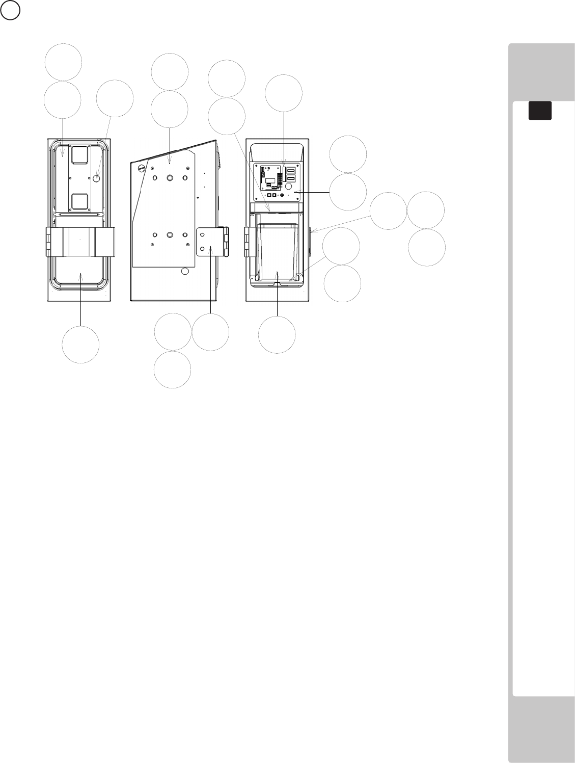
143
PARTS LIST
19
2 ASSY COIN CHUTE TOWER (RD-0300X-01UK) (D-1/1)
2
3
567
8
12
13
101 102
105
201
201
201
106
203
203
204
205
204
ITEM NO PART NUMBER DESCRIPTION QTY
**1 SSR-0301XUK COIN CHUTE TOWER 1
**2 SSR-0320UK ASSY SWITCH UNIT 1
**3 RD-0353UK CCT FLOOR 1
**5 RD-0305UK SPACER CCT STD 1
**6 RD-0352UK COIN PATH PLATE 1
**8 PP1087 BOX CASH FOR MINI DOOR 1
**12 TFF-0304UK LOCKING HASP 1
**13 TFF-0305UK BRKT PADLOCK 1
**101 220-5374-01 DOOR DFMD W/FR&LOCK C120 UNIV 1
**102 220-5575UK LOCK (J9117) KEY TO LIKE 22MM W CAM 1
**103 VTS-FRI-T-R VTS BOARD FRI TWIN 1
**104 OS1247 ALUMINIUM STICK CLIP 3
**105 220-5610-01 SR3 STD BODYBSR3INGB 1
**106 220-5727-01B DOOR CASH H.S. STS 1
**201 000-P00410-W M4X10 MSCR PAN W/FS PAS 11
**203 050-U00800 M8 NUT NYLOK PAS 4
**204 068-852216 M8 WSHR 22OD FLT PAS 4
**205 000-F00408 M4X8 MSCR CSK PAS 4
**302 LM1006LOR LOOM COIN MECH LAMP 1
**303 600-9020-44K WH EARTH 20CM M4M4 1
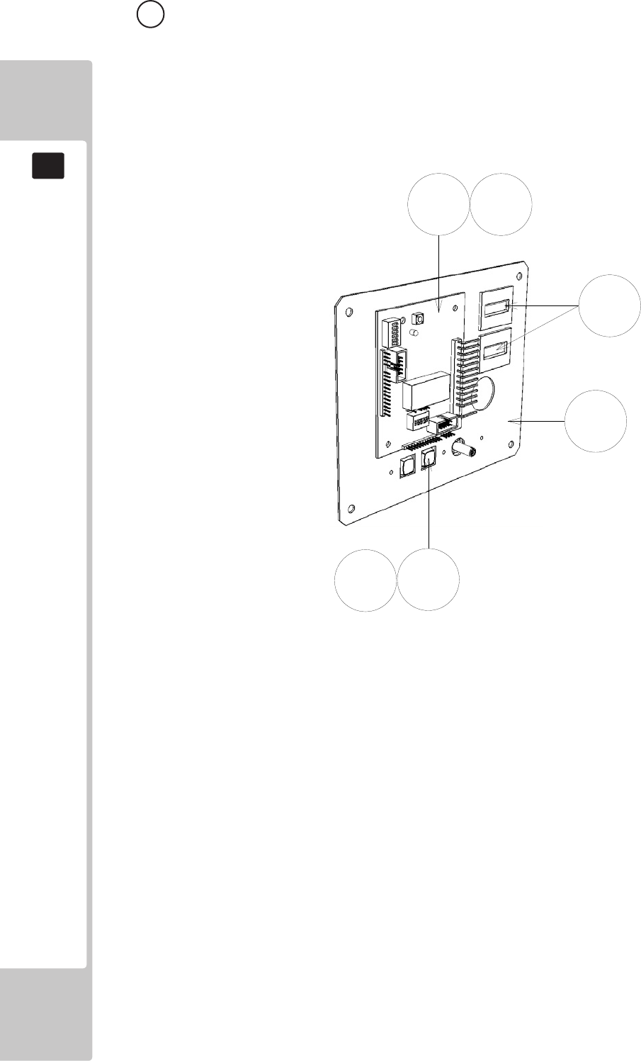
144
PARTS LIST
19
3 ASSY SW UNIT DOUBLE METER (SSR-0320UK) (D-1/1)
ITEM NO PART NUMBER DESCRIPTION QTY
***1 RD-0321UK SW BRKT DUAL COUNTER 1
***101 838-14548-01UK SW & VOL CTL BD 1
***102 280-L00706-PM STANDOFF 6.4MM HOLE PM 4
***103 EP1380-01 CREDIT BOARD EXCEL 1
***104 220-5643UK COIN METER SMALL 12V 1
***105 OS1247 ALUMINIUM STICKY CLIP 1
***107 OS1098 CRIMP BELL END SMALL 4
***108 601-0460 CABLE TIE 100MM 2
***201 000-P00308-W M3X8 MSCR PAN W/FS PAS 3
***301 RD-60003UK WH COIN HANDLING (Not Shown) 1
1
101
201
102 103
104
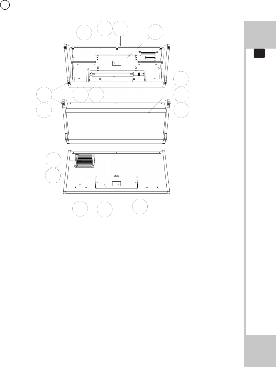
145
PARTS LIST
19
ITEM PART NUMBER DESCRIPTION QTY
**2 SRS-0501UK BILLBOARD BOX 1
**6 RD-0505UK BACK BOARD BRKT 1
**7 SSR-0506UK BACK BOARD 1
**9 RD-0508UK BACK LID 1
**11 440-WS0011UK STICKER HIVOLT/HEAT 2
**16 280-6696UK 5.5-20X6.3 WSHR SPCL 4
**101 390-240-18-2UK FL TRAY 240V 2X18W 1
**102 390-0100-18DUK FL TUBE 18W T8 600MM 2
**103 253-5460-01 AIR VENT BLACK 1
**104 280-A00964-WX ROUTER TWIST D09 SO6.4 WOOD X 8
**202 000-T00416-0B M4X16 MSCR TH BLK 9
**205 000-T00412-0C M4X12 MSCR TH CRM 3
**206 068-441616-0C M4 WSHR 16OD FLT CRM 3
**208 FAS-290034 M5X15 HEX SKT LH CAP SCR STN 4
**213 000-P00410-W M4X10 MSCR PAN W/FS PAS 6
**301 RD-60031UK WH FL UNIT 1
4 ASSY BILLBOARD (RD-0500UK) (D-1/1)
6
7
9
2
16
101
102
201
202
202
213
208
205
206
103
11
11
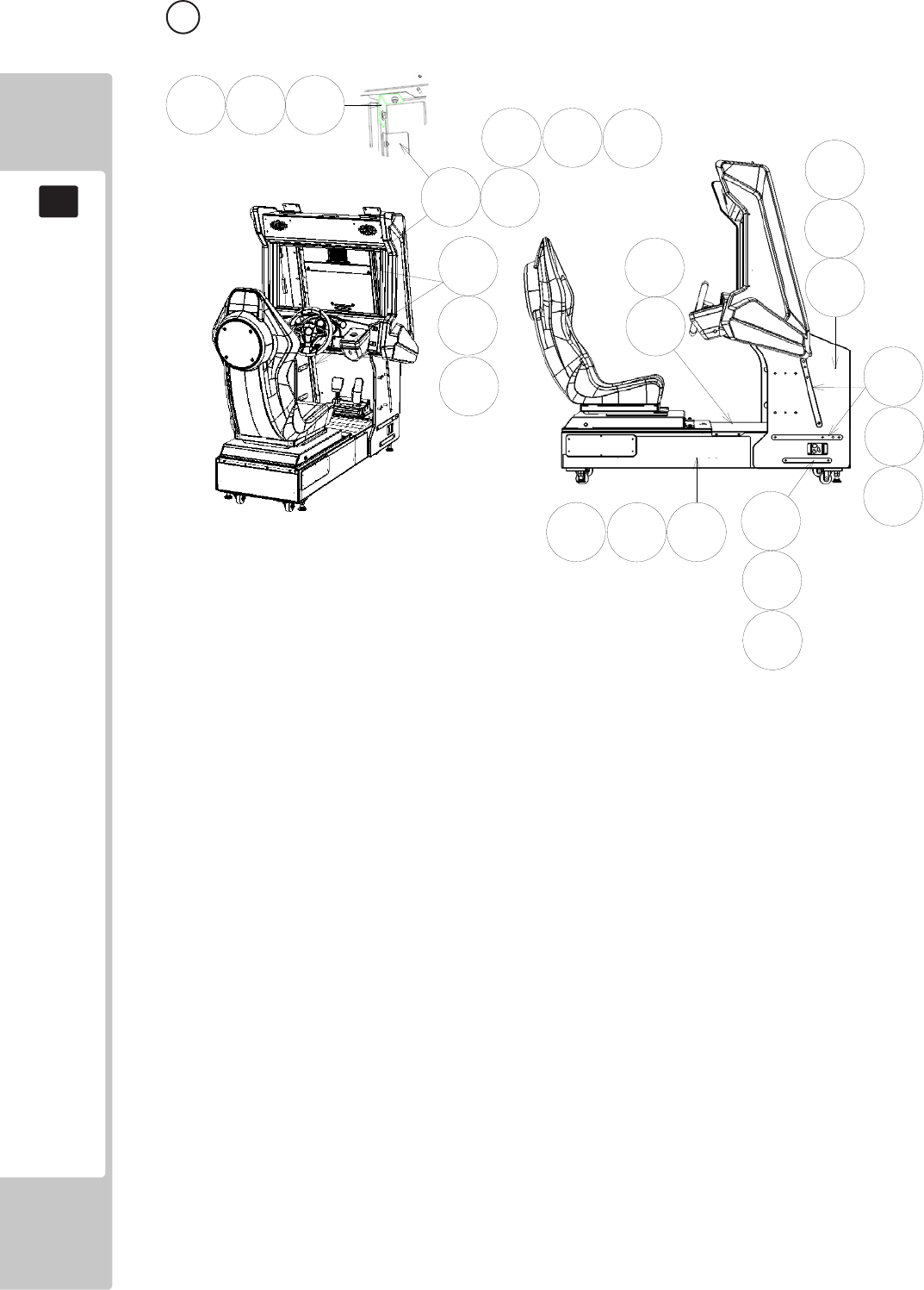
146
PARTS LIST
19
5 ASSY COCKPIT (SSR-1000UK) (D-1/1)
ITEM NO PART NUMBER DESCRIPTION QTY
**1 SSR-1200UK ASSY MONITOR CABI 1
**2 SSR-1500UK ASSY MAIN BASE 1
**4 RD-1001UK MON CABI PLATE UPPER 4
**5 RD-1002UK MON CABI PLATE LOWER 2
**7 RD-1004UK STRUT CABINET SUPPORT 2
**8 RD-1005UK BRKT OUTER CABI SUPP 2
**9 RD-1007UK BRKT TOP CABI SUPP 2
**12 RD-1502UK BASE LID F 1
**14 RD-1011UK PLATE CONN BASE BOX 1
**15 SSR-1011UK PLATE CONN BASE BOX TICKET 1
**201 030-000840-SB M8X35 BLT W/S BLK 14
**202 068-852216-0B M8 WSHR 22OD FLT BLK 18
**205 050-F00400 M4 NUT FLG SER PAS 3
**207 060-F00400 M4 WSHR FORM A FLT PAS 3
**209 000-T00512-0C M5X12 MSCR TH CRM 4
**210 030-000635-S M6X35 BLT W/S PAS 6
**211 031-000640-0B M6X40 CRG BLT BLK 8
**212 068-652016 M6 WSHR 20OD FLT PAS 14
**213 050-F00600 M6 NUT FLG SER PAS 8
**214 030-000830-S M8X30 BLT W/S PAS 4
**218 000-P00412-WB M4X12 MSCR PAN W/FS BLK 6
**305 600-9060-44K WH EARTH 60CM M4M4 2
**307 600-7009-2500UK ASSY RGB CA D-SUB 15 1
1
2
4
5
7
8
9
12
201
201
201
202
202
202
202
205
205
207
207
209
210
211 212 213
214

147
PARTS LIST
19
6 ASSY MONITOR CABI (RD-1200UK) (D-1/3)
1
3
5
6
7
12
13
17
19
20
21
22
23
10
24
4
306
105 106
201
201
201
202
202
204
204
205
206
106
107
108
109
206
207
208
209 210
211
211
213
222
224
213
213
25
14 15
214 214
215
215
216
217
218
218
218
220
220
220
221
223
8

148
PARTS LIST
19
6 ASSY MONITOR CABI (RD-1200UK) (D-2/3)
ITEM NO PART NUMBER DESCRIPTION QTY
***1 SSR-1250UK ASSY SUB MONITOR CABI 1
***3 RD-1280UK ASSY LCD MONITOR 1
***4 130-5284 SPEAKER 8OHM F01612HO NJS 2
***5 RD-1300UK ASSY MONITOR MASK 1
***6 RD-1355UK BRKT SPKR PNL LWR 1
***7 RD-2000UK ASSY CONTROL PANEL 1
***8 RD-1201UK CTRL PNL SUPPORT 1
***9 RD-1202UK CTRL PNL PLATE 2
***10 SSR-1223UK SIDE PANEL & LIGHT HOLDER L 1
**11 SSR-1224UK SIDE PANEL & LIGHT HOLDER R 1
***12 RD-1205UK BILLBOARD SUPPORT 2
***13 RD-1206UK BILLBOARD HOLDER 2
***14 RD-1207UK MONITOR CABI SPACER L 1
***15 RD-1208UK MONITOR CABI SPACER R 1
***16 RD-1212UK CONN PNL BILLBOARD 1
***17 RD-1214UK CHUTE TOWER HOLDER 2
***19 SSR-1209-AUK SIDE PANEL BLK L BLANK 1
***20 SSR-1210-AUK SIDE PANEL BLK R BLANK 1
***21 SSR-1209-BUK STICKER SIDE PANEL L 1
***22 SSR-1210-BUK STICKER SIDE PANEL R 1
***23 SSR-1356UK CENTRE PNL SPKR LEADER 1
***24 RD-0533UK LED BAR BRKT 1
***25 RD-1218UK COVER FOOTWELL LIGHT 1
***26 SSR-1225UK LIGHT COVER CHEEK SHORT 2
***27 SSR-1226UK LIGHT COVER CHEEK LONG 2
***101 253-5460-01 AIR VENT BLACK 2
***105 838-14972-07 LED BD WHITE 3X7BLOCK 1
***106 280-L00605-OS STANDOFF 6.35OD 3.56ID 4.76L 4
***107 SSR-60022-040UK WH LED ASSY 400 2
***108 SSR-60022-080UK WH LED ASSY 800 2
***109 SSR-60022-110UK WH LED ASSY 1100 2
***110 280-L1316-OS STANDOFF 12.7OD 5.56ID 15.88L 4
***201 000-P00416-WB M4X16 MSCR PAN W/FS BLK 13
***202 050-F00600 M6 NUT FLG SER PAS 6
***204 068-652016 M6 WSHR 20OD FLT PAS 6
***205 012-P03512-F N6X1/2” S/TAP FLG PAS 8
***206 068-441616-0B M4 WSHR 16OD FLT BLK 27
***207 FAS-290017 M8X30 SKT CAP BH BLK 6
***208 060-F00800-0B M8 WSHR FORM A FLT BLK 6
***209 068-852216-0B M8 WSHR 22OD FLT BLK 2
***210 030-000835-SB M8X35 BLT W/S BLK 4
***211 012-P03512-F N6X1/2” S/TAP FLG PAS 30
***213 000-T00412-0B M4X12 MSCR TH BLK 20
***214 012-F003512 N6X1/2” S/TAP CSK PAS 12
***215 030-000620-SB M6X20 BLT W/S BLK 8

149
PARTS LIST
19
6 ASSY MONITOR CABI (RD-1200UK) (D-3/3)
ITEM NO PT NUMBER DESCRIPTION QTY
***216 068-652016-0B M6 WSHR 20OD FLT BLK 4
***217 000-T00416-0B M4X16 MSCR TH BLK 14
***218 050-F00400 M4 NUT FLG SER PAS 8
***220 060-F00400 M4 WSHR FORM A FLT PAS 8
***221 000-P00312-PN M3X12 MSCR PAN NYLON NAT 4
***222 000-P00420-WB M4X20 MSCR PAN W/FS BLK 4
***223 068-441616 M4 WSHR 16OD FLT PAS 2
***224 000-P00410-W M4X10 MCR PAN W/FS PAS 2
***225 000-F00316 M3X16 MSCR CSK PAS 4
***226 060-F00500 M5 WSHR FORM A FLT PAS 4
***227 000-T00425-0B M4X25 MSCR TH BLK 6
***301 RD-60004UK WH LED FRONT CABI 1
***303 SSR-60017UK WH CNTL PNL EXTN 1
***304 RD-60029UK WH AC BB LCD 1
***306 RD-60038-020UK WH LED ASSY 200 1
***307 RD-60020UK WH SPEAKER D 2
***308 RD-60018UK WH RACE LEADER 1
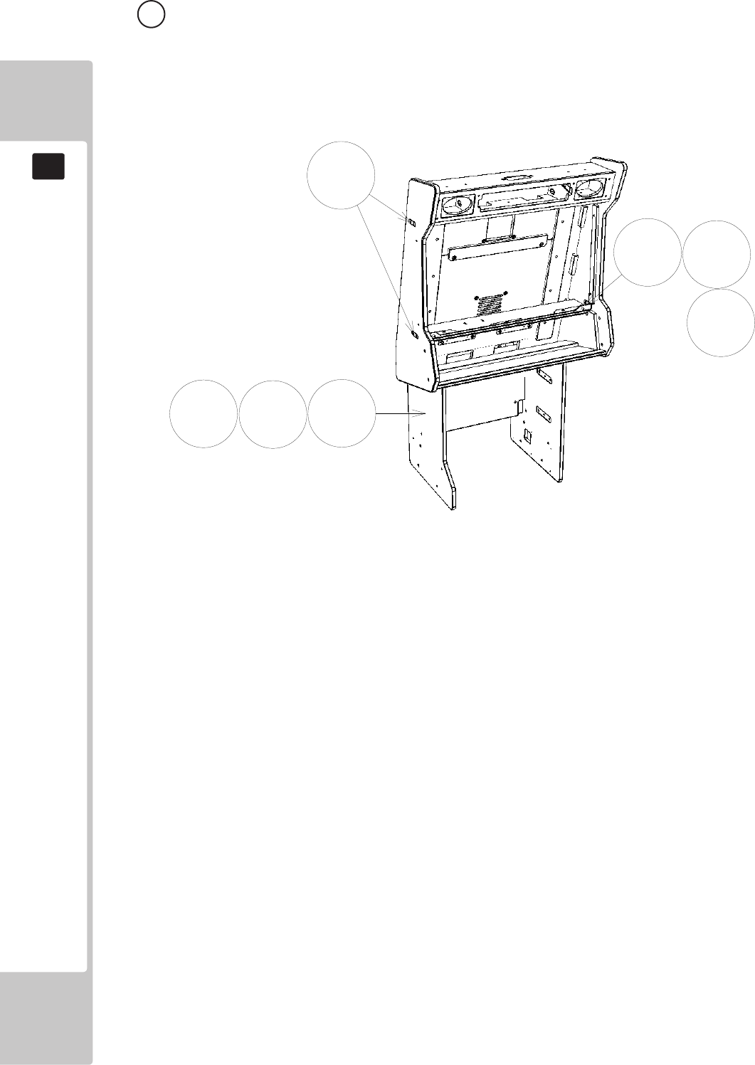
150
PARTS LIST
19
7 ASSY SUB MONITOR CABI (SSR-1250UK) (D-1/1)
1
5
6
207
208
204
205
ITEM NO PART NUMBER DESCRIPTION QTY
****1 SSR-1251UK MONITOR CABINET 1
****5 RD-1255UK MONITOR SUPPORT 2
****6 RD-1256UK MONITOR SUPPORT PLATE 4
****204 030-00630-SB M8X30 BLT W/S BLK 14
****205 068-652016 M6 WSHR 20OD FLT PAS 3
****207 000-P00430-WB M4X30 MSCR PAN W/FS BLK 4
****208 068-441616-0B M4 WSHR 16OD FLT BLK 4
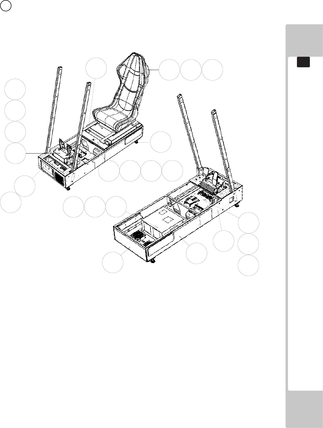
151
PARTS LIST
19
2
4
5
6
83
9
17
12
13
1
201 202
203
204 205
203
206
216
207
206
207
202
7
8 ASSY MAIN BASE (SSR-1500UK) (D-1/2 )

152
PARTS LIST
19
ITEM NO PART NUMBER DESCRIPTION QTY
***1 SSR-1520UK ASSY BASE BOX 1
***2 SSR-1540UK AC UNIT 1
***3 SSR-1600UK ASSY ADJUSTABLE SEAT 1
***4 SPG-2200-01-CN ASSY ACCEL & BRAKE CHINA 1
***5 SSR-4500UK ASSY MAIN BD 1
***6 SSR-4600UK ASSY ELEC BD 1
***7 SSR-1535UK ASSY BASE LID R 1
***8 RAL-2007X RUBBER HOLDER R TWIN 1
***9 RAL-2008X RUBBER HOLDER L TWIN 1
***11 SSR-1503UK STICKER MAIN BASE L 1
***12 SSR-1504UK STICKER MAIN BASE R 1
***13 SSR-1505UK STICKER MAIN BASE REAR 1
***17 SPG-2224UK PEDAL GASKET 1
***110 EP1392 A15P VGA GENDER CHANGE 1
***201 000-P00408-WB M4X8 MSCR PAN W/FS BLK 4
***202 032-000425 M4X25 W/BLT PAS 4
***203 068-441616 M4 WSHR 16OD FLT PAS 4
***204 050-U00800 M8 NUT NYLOK PAS 6
***205 068-852216 M8 WSHR 22OD FLT PAS 6
***206 030-000825-SB M8X25 BLT W/S BLK 8
***207 060-F00800-0B M8 WSHR FORM A FLT BLK 8
***216 008-T00512-0B M5X12 TMP PRF TH BLK 4
***215 000-T00412-0B M4X12 MSCR TH BLK 8
***301 600-7269-0150UK ASSY LAN CABLE 150CM 1
***302 RD-60015UK WH AUDIO LED EXT 1
***303 RD-60023UK WH PEDALS EXT 1
***304 SSR-60019UK WH BASE BOX TO COCKPIT 1
***305 SSR-60009UK WH ENCODER & MOTOR B 1
***307 600-7009-1800UK ASSY RGB CA D-SUB 15 1
***308 RD-60037UK WH AC BASE EXTN 1
***310 600-9010-44K WH EARTH 10CM M4M4 1
***311 600-9020-44K WH EARTH 20CM M4M4 1
8 ASSY MAIN BASE (SSR-1500UK) (D-2/2)
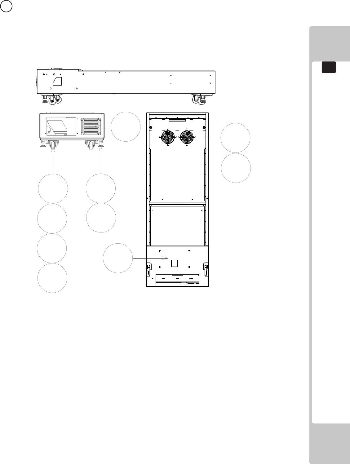
153
PARTS LIST
19
9 ASSY BASE BOX (SSR-1520UK) (D-1/1 )
1
101
102 103
104
201
204
205
207
206
ITEM NO PART NUMBER DESCRIPTION QTY
****1 SSR-1531UK MAIN BASE BLANK 1
****101 FN1012 FAN GUARD METAL 120MM 2
****102 MA1007 CASTOR SWIVEL 63MM 4
****103 601-5699UK-01 LEG ADJ M16X100 1L/NUT 4
****104 253-5460-01 AIR VENT BLACK 1
****202 050-U00400 NUT M4 NYLOK PAS 4
****204 030-00816 M8X16 BLT PAS 16
****205 060-S00800 M8 WSHR SPR PAS 16
****206 000-T00416-0B M4X16 MSCR TH BLK 4
****207 060-F00800-SB M8 WSHR FORM A FLT BLK 16
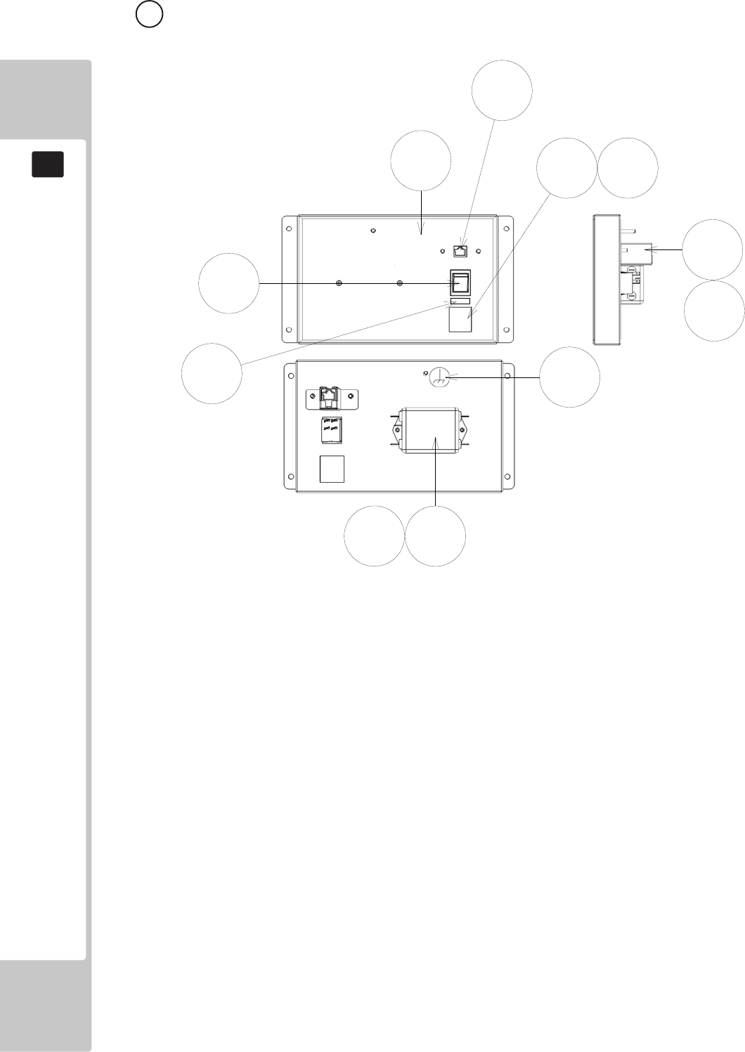
154
PARTS LIST
19
10 ASSY AC UNIT (SSR-1540UK) (D-1/1 )
1
2
3
101 102
103
104
107
109
201
202
ITEM NO PART NUMBER DESCRIPTION QTY
****1 RD-1541UK AC BRKT 1
****2 TFF-0402UK CONN COVER 1
****3 LB1096 STICKER PROTECTIVE EARTH 1
****101 EP1302 EUROSOCKET FUSED 10A 250VAC 1
****102 514-5078-5000 FUSE 5X20 CERAMIC SB 5000mA 2
****103 SW1109 SWITCH ROCKER 250V AC 1
****104 EP1419 FILTER SCHAFFNER 2030-16-06 1
****107 EP1391 COUPLER INLINE LAN RJ45 1
****108 310-5029-D508 HEAT SHRINK SLEEVING 50.8DIA 4
****109 LB1126-5-250 FUSE LABEL 5A 250V 1
****201 000-P00308-W M3X8 MSCR PAN W/FS PAS 2
****202 050-F00400 M4 NUT FLG SER PAS 4
****301 TFF-60001UK WH AC IN 1
****302 600-9020-44K WH EARTH 200MM M4/M4 1
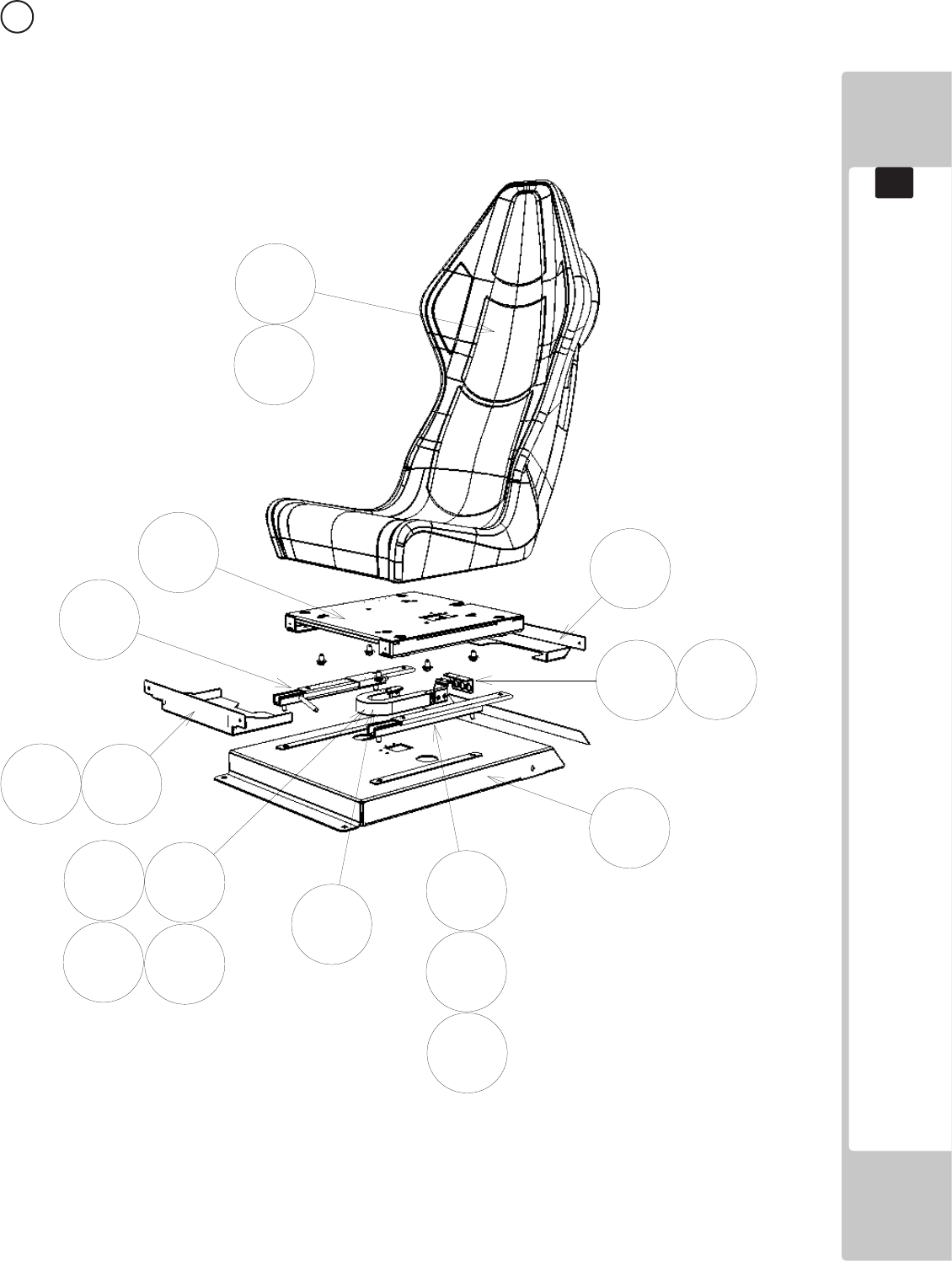
155
PARTS LIST
19
11 ASSY ADJ SEAT (SSR-1600UK) (D-1/2)
1
2
3
4
5
12
13
15
101
102
202
202 204
206
212
214
207
103

156
PARTS LIST
19
11 ASSY ADJ SEAT (SSR-1600UK) (D-2/2)
ITEM NO PART NUMBER DESCRIPTION QTY
****1 SSR-1650UK ASSY SEAT 1
****2 SSR-1601UK SEAT BASE 1
****3 RD-1602UK SEAT TRAY 1
****4 RD-1603UK CABLE BEAR BRKT UPPER 1
****5 RD-1604UK CABLE BEAR BRKT LOWER 1
****6 RD-1605UK PROTECT RUBBER 2
****12 RD-1611UK TRAY COVER FRONT 1
****13 RD-1612UK TRAY COVER REAR 1
****15 SSR-1614UK BKT PNL MOUNT 1
****101 601-9059-91 SEAT RAIL L 1
****102 601-9060-91 SEAT RAIL R 1
****103 601-6981-009 CABLE BEAR L=009 1
****202 000-P00408-W M4X8 MSCR PAN W/FS PAS 4
****203 000-P00512-W M5X12 MSCR PAN W/FS PAS 4
****204 050-U00800 M8 NUT NYLOK PAS 8
****206 068-852216 W8 WSHR 22OD FLT PAS 14
****207 030-000820-S M8X20 BLT W/S PAS 6
****212 000-T00408-0B M4X8 MSCR TH BLK 10
****214 000-P00412-W M4X12 MSCR PAN W/FS 2
****301 RD-60025UK WH CABLE BEAR 1
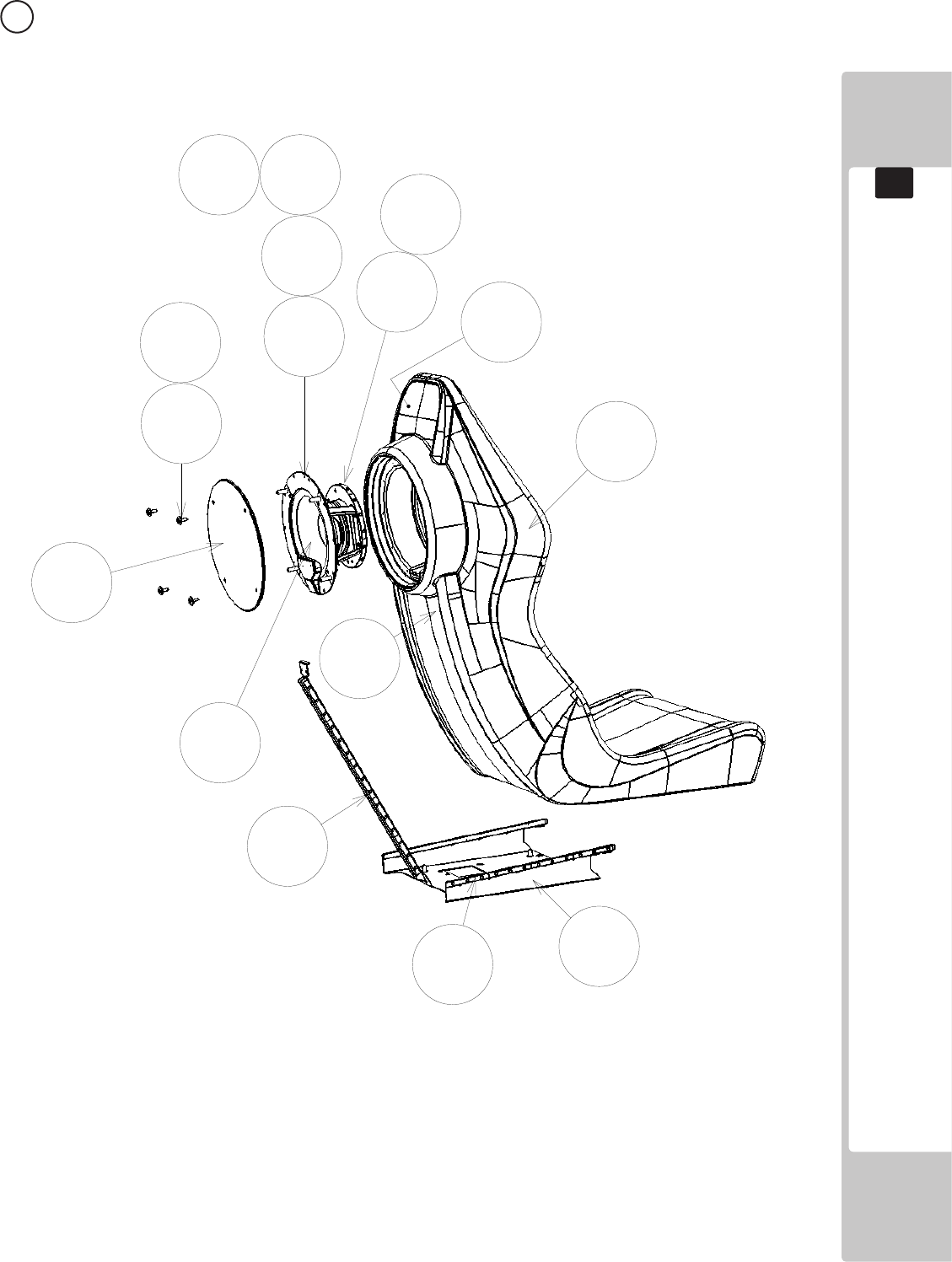
157
PARTS LIST
19
12 ASSY SEAT LIT (SSR-1650UK) (D-1/2)
42
3
1
5
6
7
102
201
202
203204 202
8
103
301

158
PARTS LIST
19
12 ASSY SEAT LIT (SSR-1650UK) (D-2/2)
ITEM NO PART NUMBER DESCRIPTION QTY
*****1 SSR-1670UK ASSY WOOFER 1
*****2 SSR-1680UK ASSY WOOFER LED 1
*****3 SSR-1651-AUK SEAT SSR BLANK 1
*****4 SSR-1652UK WOOFER BKT B 1
*****5 SSR-1654UK WOOFER DESIGN PLATE 1
*****6 SSR-1651-BUK STICKER SEAT UPPER 1
*****7 SSR-1651-CUK STICKER SEAT LOWER 1
*****8 SSR-1655UK BRKT BASE LWR SEAT LIGHT
*****102 280-6686-01UK 4.5X16X4 SP WSHR 4
*****103 SSR-60022-040UK WH LED ASSY 400 2
*****106 280-0003UK M5 SHLDR WSHR INSUL NYLON 4
*****201 FAS-290042 M4X12 HEX SKT LH CAP SCR STN 4
*****202 012-P00416-FZ N8X5/8" S/TAP FLG OZ 12
*****203 030-00816-S M8X16 BLT W/S PAS 4
*****204 068-852216 M8 WSHR 22OD FLT PAS 4
*****301 SSR-60001UK WH ASSY SEAT SPINE 1
*****302 SSR-60023UK WH SEAT MAIN 1
*****304 600-9020-44K WH EARTH 20CM M4M4 1
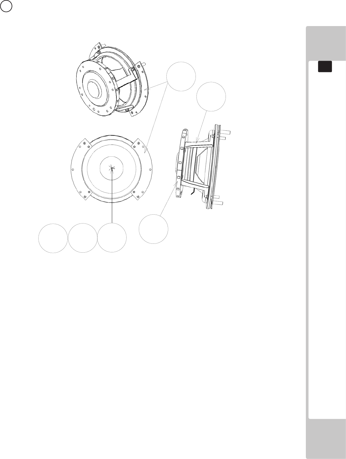
159
PARTS LIST
19
13 ASSY WOOFER (SSR-1670UK) (D-1/1)
1
4
101 301
201
202
ITEM NO PART NUMBER DESCRIPTION QTY
******1 SSR-1671UK WOOFER BRKT A 2
******4 SSR-1674UK BRKT RING SUPPORT 2
*****101 130-5280 WOOFER 4OHM 80W SILVER RNE 1
*****201 060-F00400 M4 WSHR FORM A FLT PAS 4
*****202 050-U00400 M4 NUT NYLOK PAS 4
*****301 SSR-6002UK WH ASSY WOOFER RING 1
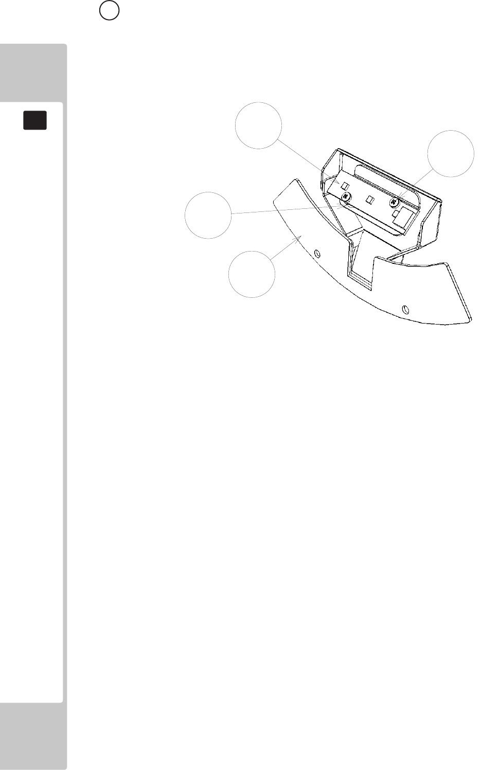
160
PARTS LIST
19
1
101
102
201
14 ASSY WOOFER LED (SSR-1680UK) (D-1/1)
ITEM NO PART NUMBER DESCRIPTION QTY
******1 SSR-1681UK WOOFER BRKT C 1
******101 838-14973-01 LED BD RGB 3X1BLOCK 1
******102 280-L00605-OS STANDOFF 6.35OD 3.56ID 4.76L 2
******201 000-P00312-PN M3X12 MSCR PAN NYLON NAT 2
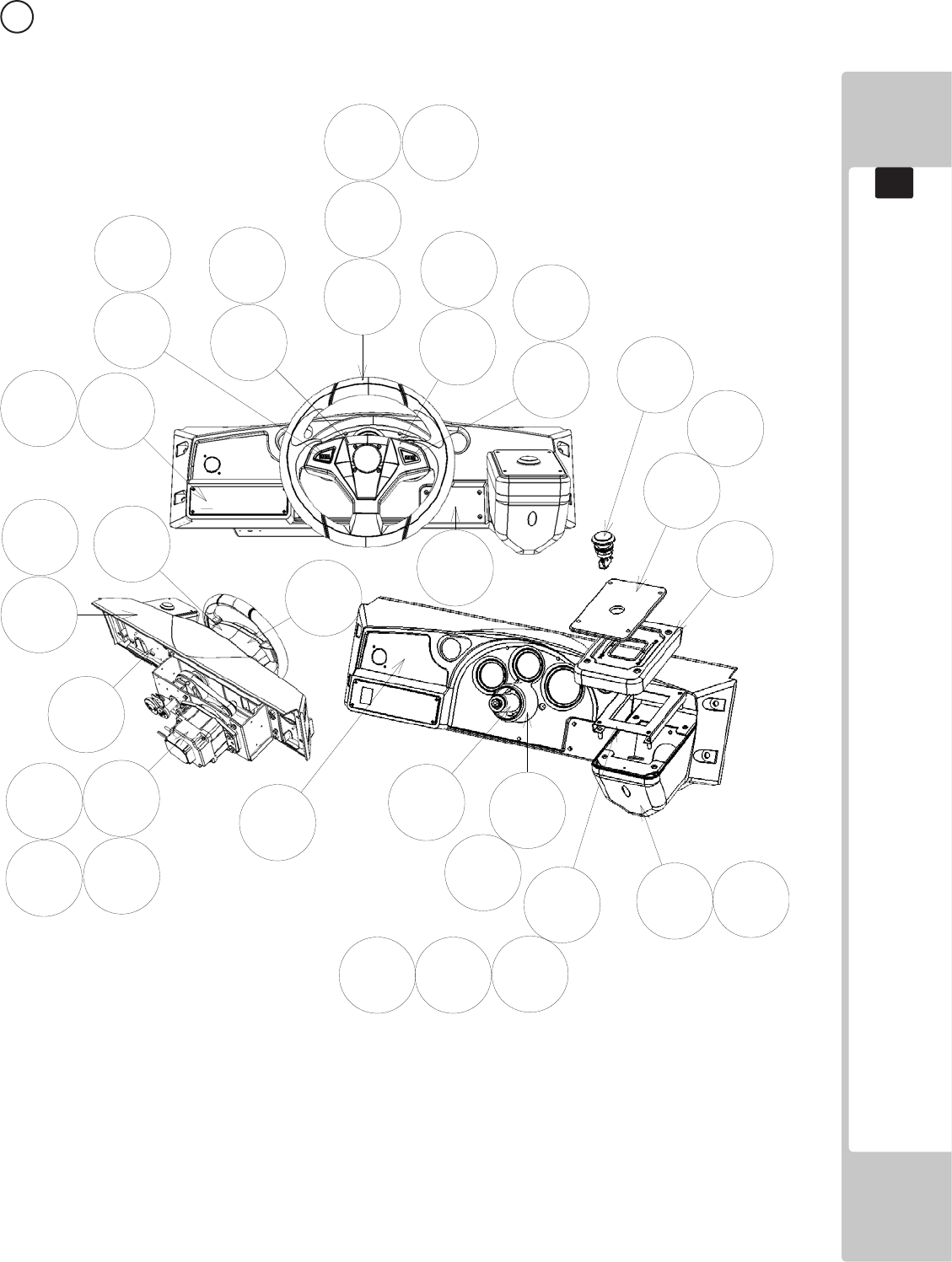
161
PARTS LIST
19
15 ASSY CONTROL PANEL (SSR-2000UK) (D-1/2)
1
2
3
45
6
7
9
10
8
9
12
13
14
16
17
18
21 22
105
107 108
201
202
203 204 205
206
214
215216
217
208
208
209
211
203 213

162
PARTS LIST
19
15 ASSY CONTROL PANEL (SSR-2000UK) (D-2/2)
ITEM NO PART NUMBER DESCRIPTION QTY
****1 SSR-2100UK ASSY SW PLATE W/O BUTTON 1
****2 RTV-2500 ASSY HANDLE MECH 1
****3 RNE-2001 STEERING WHEEL 1
****4 RNE-2002 FRONT CENTER COVER 1
****5 RNE-2003 FRONT COVER 1
****6 RNE-2004 REAR COVER L 1
****7 RNE-2005 REAR COVER R 1
****8 RNE-2006 HANDLE COLLAR CAP 1
****9 RNE-2007UK CONTROL PANEL BKT 1
****10 SSR-2001UK CTRL PANEL COVER 1
****11 RNE-2009 HANDLE COLLAR 1
****12 SSR-2013UK BASE SHIFTER COVER A 1
****13 DYN-1222 SHIFT COVER A 1
****14 DYN-1223X SHIFT COVER B 1
****16 SSR-0002UK STICKER SUB INSTRUCT 1
****17 DYN-0010UK DENOMI PLATE 1
****18 SSR-2010UK PATE START 1
****21 SSR-2015UK LEGEND BTN L 1
****22 SSR-2016UK LEGEND BTN R 1
****102 280-A01200-A ROUTER TWIST D12 ADH 4
****103 280-A02000-A ROUTER TWIST D20 ADH 1
****105 509-6006-B BTN CHROME BLUE HALO 2
****107 509-6218-01 SW PB 1M W/LED RGB BOOST L 1
****108 509-6219-01 SW PB 1M W/LED RGB BOOST R 2
****201 020-000820 M8X20 BLT PAS 1
****202 060-F00800 M8 WSHR FORM A FLT PAS 4
****203 060-S00800 M8 WSHR SPR PAS 5
****204 050-U00800 M8 NUT NYLOK PAS 4
****205 000-P00412-W M4X12 MSCR PAN W/FS PAS 3
****206 030-000820-S M8X20 BLT W/S PAS 4
****208 008-T00416-0B M4X16 TMP PRF TH BLK 7
****209 000-P00308-W M3X8 MSCR PAN W/FS PAS 3
****210 000-P00310-W M3X10 MSCR PAN W/FS PAS 6
****211 FAS-290082 M3X16 SKT CAP BLK 4
****213 060-F01600 M16 WSHR FORM A FLT PAS 2
****214 0000-T00416-0B M4X16 MSCR TH BLK 6
****215 050-F00600 M6 NUT FLG SER PAS 4
****216 060-F00600 M6 WSHR FORM A FLT PAS 4
****217 008-T00420-0B M4X20 TMP PRF TH BLK 4
****304 RNE-60104 WH STEERING WHEEL EXT 1
****305 RNE-60105 WH STEERING BUTTON 1
****312 600-9120-44K WH EARTH 120CM M4M4 1
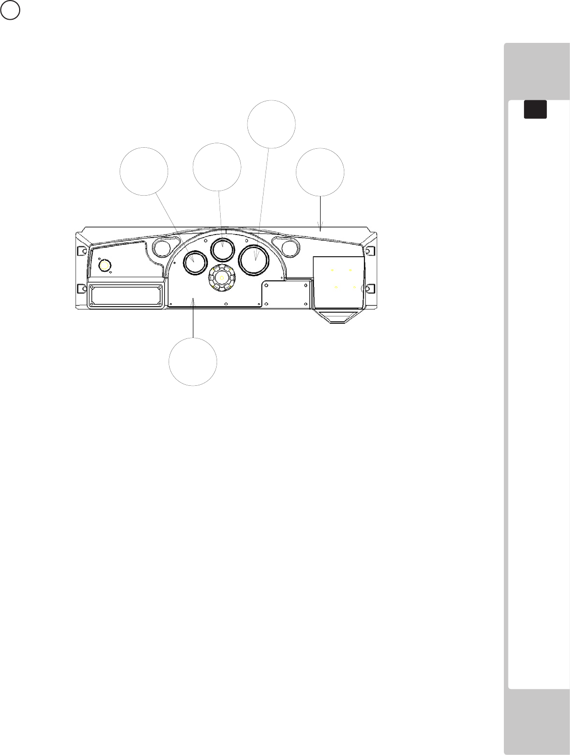
163
PARTS LIST
19
16 CONTROL PANEL COVER (SSR-2001UK) (D-1/1)
1
23
4
5
ITEM NO PART NUMBER DESCRIPTION QTY
****1 RNE-2008-A CONTROL PANEL COVER BL 1
****2 SSR-2001-CUK DESIGN PLATE L 1
****3 SSR-2001-DUK DESIGN PLATE M 1
****4 SSR-2001-EUK DESIGN PLATE R 1
****5 SSR-2001-BUK METER PANEL 1
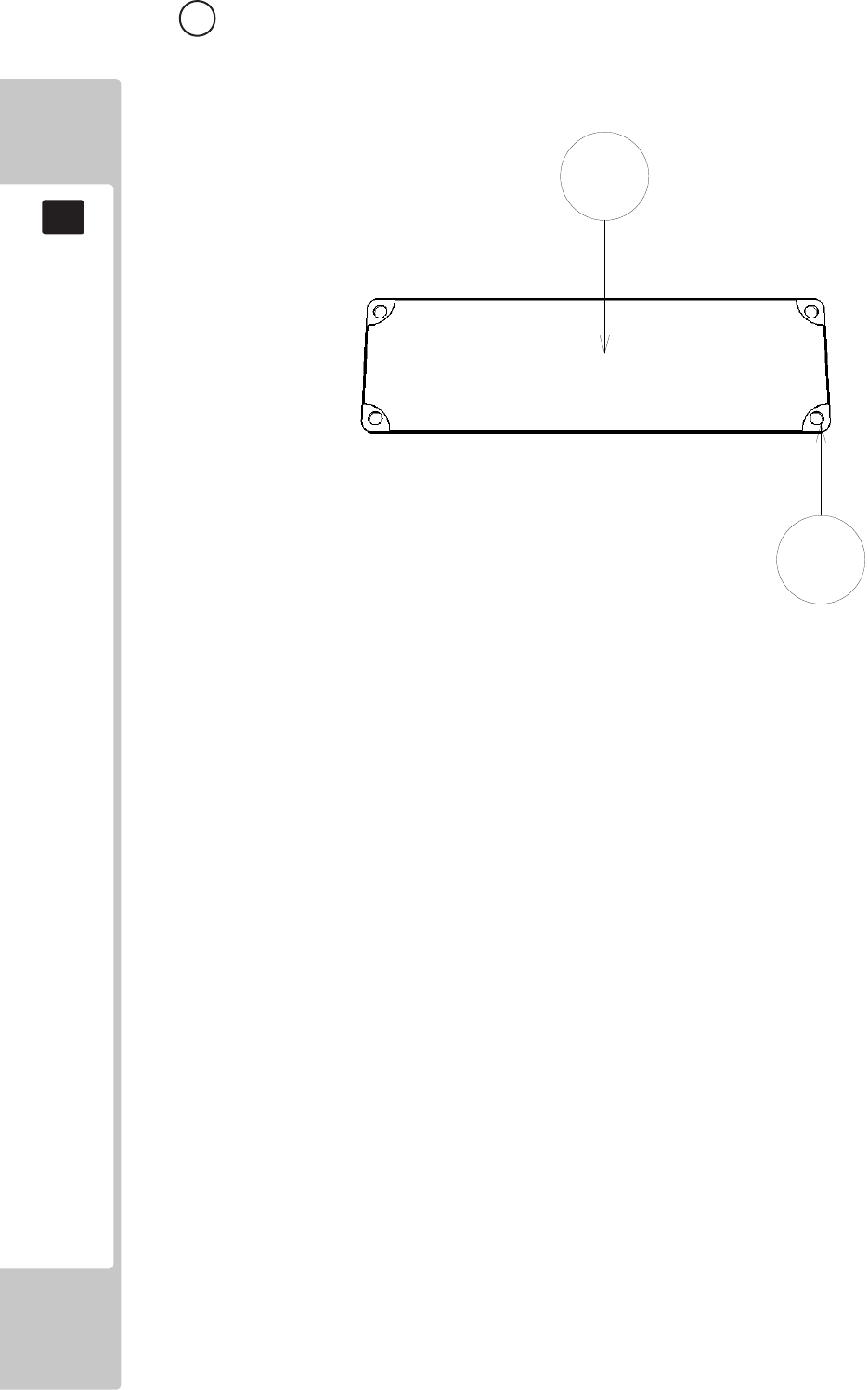
164
PARTS LIST
19
17 ASSY SW PLATE W/O BUTTON (SSR-2100UK) (D-1/1)
1
2
ITEM NO PART NUMBER DESCRIPTION QTY
****1 SSR-2101UK STICKER W/O BUTTON 1
****2 SSR-2102UK PLATE BUTTON BLANK 1
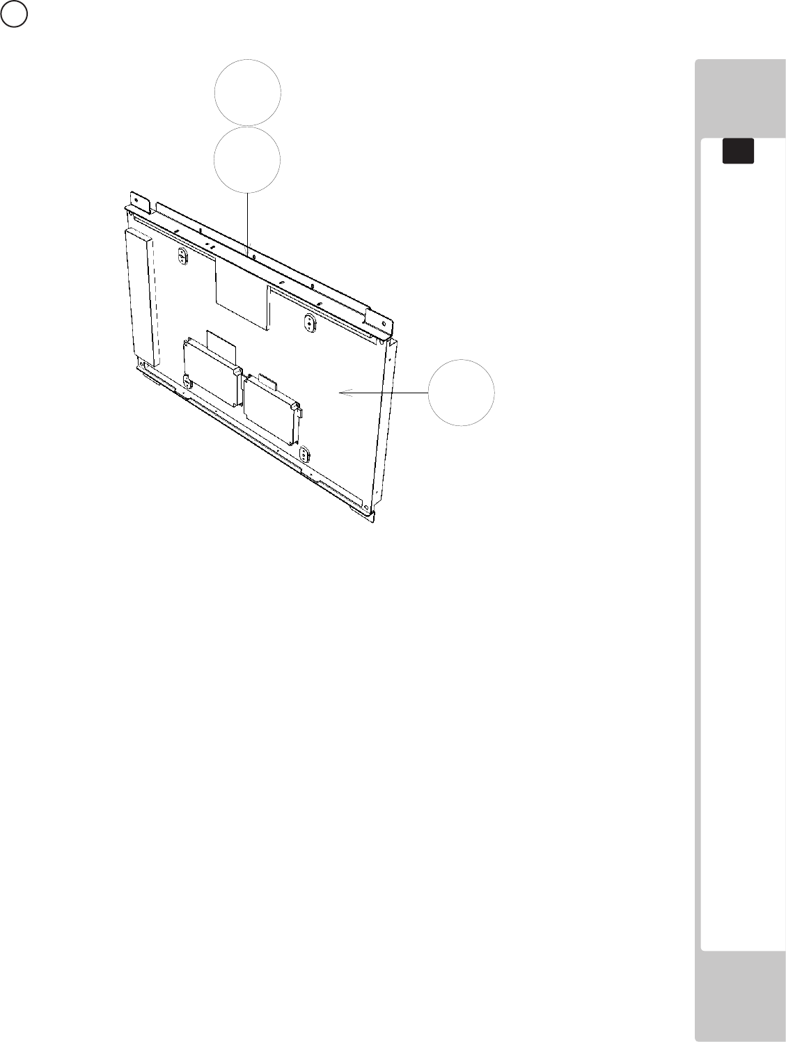
165
PARTS LIST
19
18 ASSY LCD MONITOR (RD-1280UK) (D-1/1)
201
1
101
ITEM NO PART NUMBER DESCRIPTION QTY
****1 RD-1281UK LCD BRKT 2
****101 200-6032-01DT DISPLAY 32” LCD LTI320AA02 1
****201 000-P00416-W M4X16 MSCR PAN W/FS PAS 6
****301 RD-60030UK WH LCD PSU 1
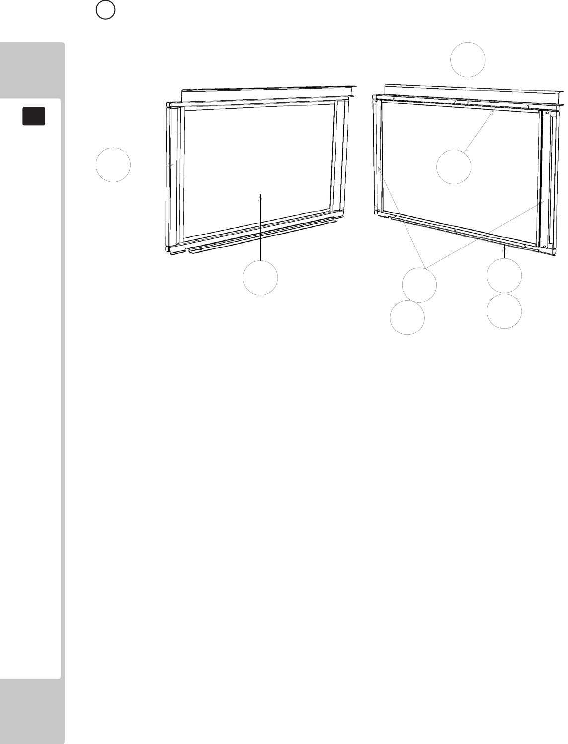
166
PARTS LIST
19
19 ASSY MONITOR MASK (RD-1300UK) (D-1/1)
1
24
3
3
101
201
201
ITEM NO PART NUMBER DESCRIPTION QTY
****1 RD-1301UK MONITOR MASK 1
****2 RD-1308UK PROTECTIVE GLASS LCD 32V 1
****3 RD-1302UK GLASS HOLDER UL 2
****4 RD-1303UK GLASS HOLDER LR 2
****101 OS1230 FOAM STRIP 2mm X 10mm 4.6
****201 050-F00400 M4 NUT FLG SER PAS 10
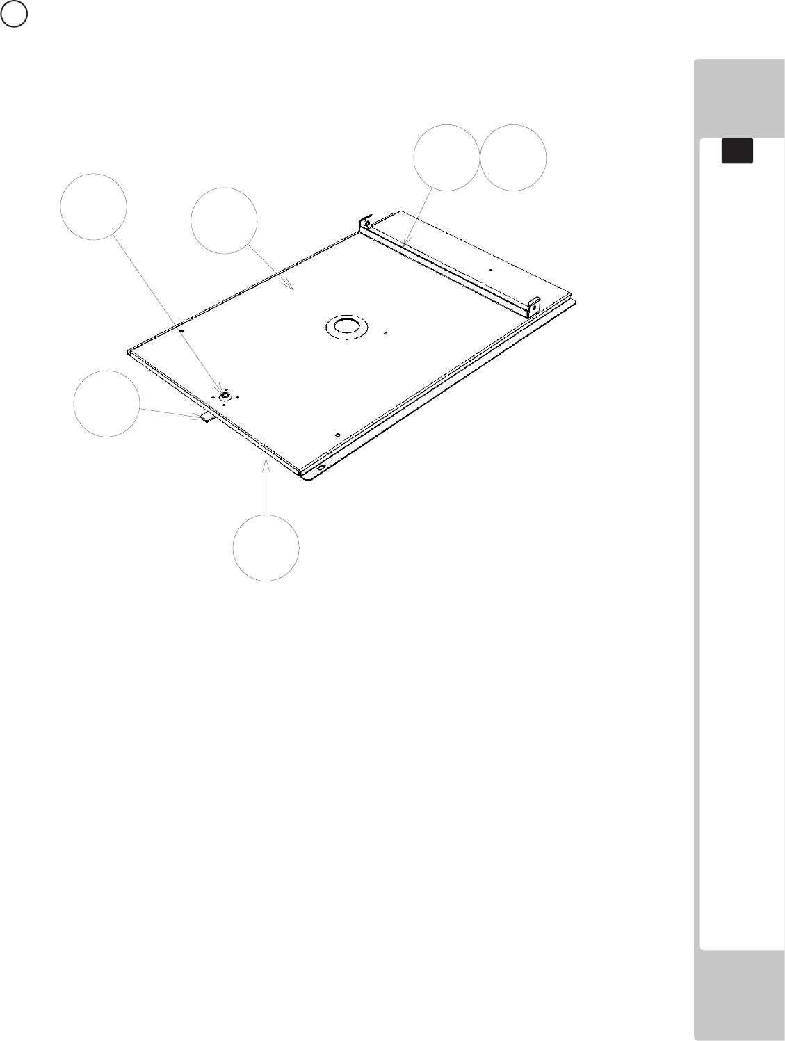
167
PARTS LIST
19
20 ASSY BASE LID R (SSR-1535UK) (D-1/1)
1
2
3
6
101
204
ITEM NO PART NUMBER DESCRIPTION QTY
****1 SSR-1538UK BASE LID R 1
****2 DUT-1511-CUK GASKET STRIP 1
****3 DUT-1511-DUK LOCK TONGUE DUT 1
****6 RD-1536UK SEAT HOLDER 1
****101 220-5575UK LOCK 1
****104 280-A00748-PM ROUTER TWIST D7.SO4.8 PANEL M 4
****201 050-F00400 M4 NUT FLG SER PAS 1
****204 030-000816-S M8X16 BLT W/S PAS 2
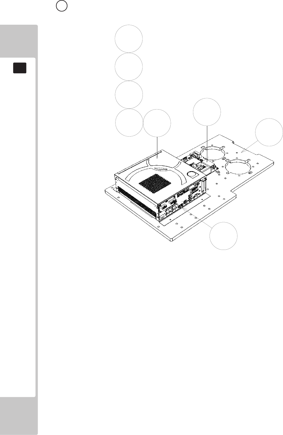
168
PARTS LIST
19
21 ASSY MAIN BOARD (RD-4500UK) (D-1/1)
ITEM NO PART NUMBER DESCRIPTION QTY
****1 SSR-4501UK WOODEN BASE MAIN BD 1
****2 847-0001D-02 ASSY CASE WDE W 1GB EXP 1
****3 253-5644-021BG KEY CHIP RGW SSAR 1
****4 610-0816-0029 DVD-SOFT KIT SSAR GL 1
****5 LB1111 STICKER PLEASE RECYCLE 1
****101 400-5483 SW REGU EADP-130CF A DELTA 1
****102 280-A01264-WX ROUTER TWIST D12 S06.4 WOOD X 5
****103 280-A02064-WX ROUTER TWIST D20 S06.4 WOOD X 5
****108 LB1101 STICKER WARNING BATTERY 1
****201 000-P00416-W M4X16 MSCR PAN W/FS PAS 4
4
****301 SSR-60005UK WH DC RINGWIDE 1
****302 SSR-60016UK WH AC GAMEBOARD 1
****303 SSR-60006UK WH 5V I/O 1
****304 SSR-60007UK WH COMS A 1
1
2
3
4
5
101
108
201
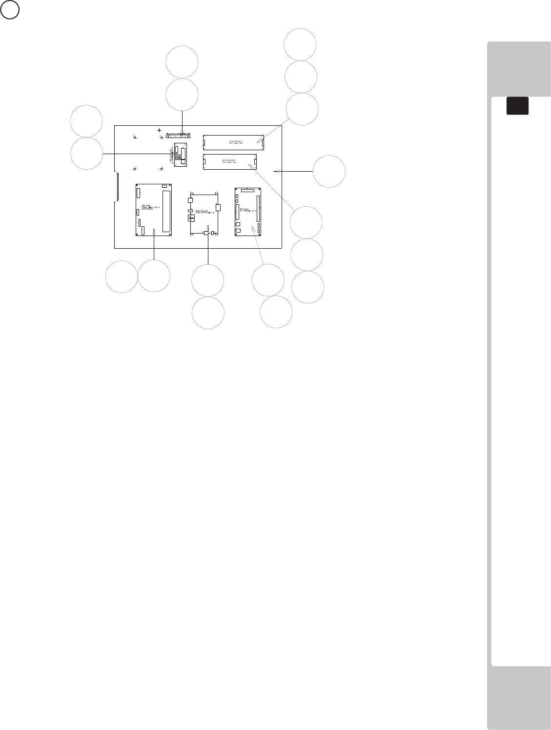
169
PARTS LIST
19
22 ASSY ELEC BOARD (RD-4600UK) (D-1/1)
1
2
5
102
103
104
107
108
111
111
201 201
201
202 202
203 202
ITEM NO PART NUMBER DESCRIPTION QTY
****1 SSR-4601UK WOODEN BASE ELEC BD 1
****2 838-15069 MOTOR DRIVE BD RS232/422 1
****5 CFB-4003-01UK EARTH PLATE 1
****102 838-14515-A09 SOUND AMP ANALOG IN 1
****103 400-050-024-01 PSU 24VDC 50W MW LPS-50-24 1
****104 400-075-012-01 PSU 12V DC 75W MW LPS-75-12 1
****107 837-14572 I/O BOARD 3 FOR JVS 1
****108 838-14551-02UK AC DISTRIBUTION BD 1
****111 OS1011 PCB FEET RICHCO LCBS-L-5-01 20
****112 280-A01264-WX ROUTER TWIST D12 SO6.4 WOOD X 14
****113 280-A02064-WX ROUTER TWIST D20 SO6.4 WOOD X 10
****201 012-P00325 N4X1” S/TAP PAN PAS 12
****202 012-P03506-F N6X1/4” S/TAP FLG PAS 16
****203 012-P03512-F N6X1/2” S/TAP FLG PAS 2
****301 RD-60001UK WH AC TO DIST 1
****302 SSR-60002UK WH AC DISTRIBUTION 1
****303 SSR-60003UK WH DC I/O 1
****304 SSR-60007UK WH COMMS A 1
****305 SSR-60008UK WH ENCODER & MOTER A 1
****306 SSR-60004UK WH DC 12V OUT 1
****307 SSR-60010UK WH SPEAKER A 1
****308 SSR-60018UK WH P PORT A 1
****309 SSR-60013UK WH I/O 1
****310 600-7141-100UK CABEL JVS TYPE A-B 100CM 1
****311 600-9050-44K WH EARTH 50CM M4M4 1
****312 600-7919-200UK CA ST JACK TO PHONO 1
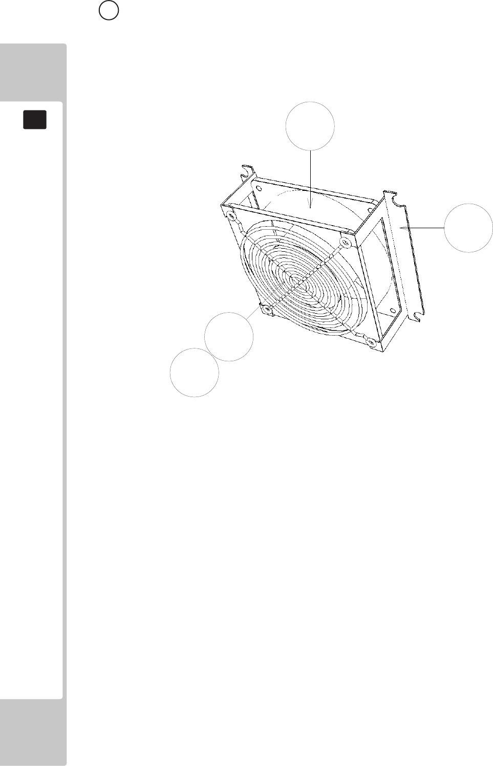
170
PARTS LIST
19
23 ASSY 240V FAN (ST-1340UK) (D-1/1)
1
101
102
201
ITEM NO PART NUMBER DESCRIPTION QTY
****1 105-5340-01 FAN BRKT LONG 2
****101 260-0024-01UK FAN AC AXIAL DP200A 1
****102 FN1012 FAN GUARD METAL 120MM (FG-12) 1
****201 000-P00312-W M3X12 MSCR PAN W/FS PAS 4
****301 ST-60026UK WH FAN 1
WIRE COLOUR CODE TABLE
20
171
The color codes for the wires used in the diagrams in the following chapter are as follows.
A PINK
B SKY BLUE
C BROWN
D PURPLE
E LIGHT GREEN
Wires other than those of any of the above 5 single colors will be displayed by 2 alphanumeric
characters.
1 RED
2 BLUE
3 YELLOW
4 GREEN
5 WHITE
7 ORANGE
8 BLACK
9 GRAY
If the right-hand side numeral of the code is 0, then the wire will be of a single color shown by the left-
hand side numeral (see the above).
Note 1: If the right-hand side numeral is not 0, that particular wire has a spiral color code. The left-
hand side character shows the base color and the right-hand side one, the spiral color.
<Example> 51………WHITE/RED
RED WHITE
Note 2: The character following the wire color code indicates the size of the wire.
U : AWG16
K : AWG18
L : AWG20
None : AWG22
The DC power wire color for this product is dierent from previous SEGA titles. Working
from the previous wire colors will create a high risk of re.
20 WIRE COLOUR CODE TABLE
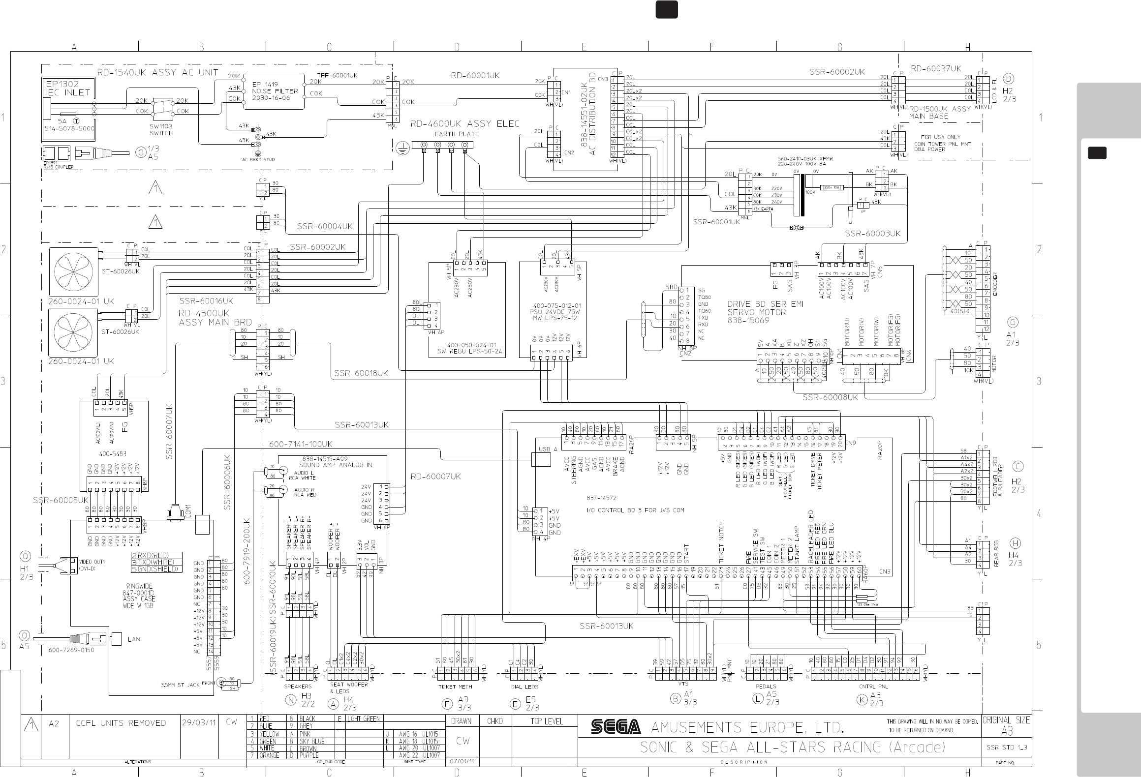
172
WIRING DIAGRAMS
21
(D-1/3) 21 SCHEMATIC DIAGRAMS
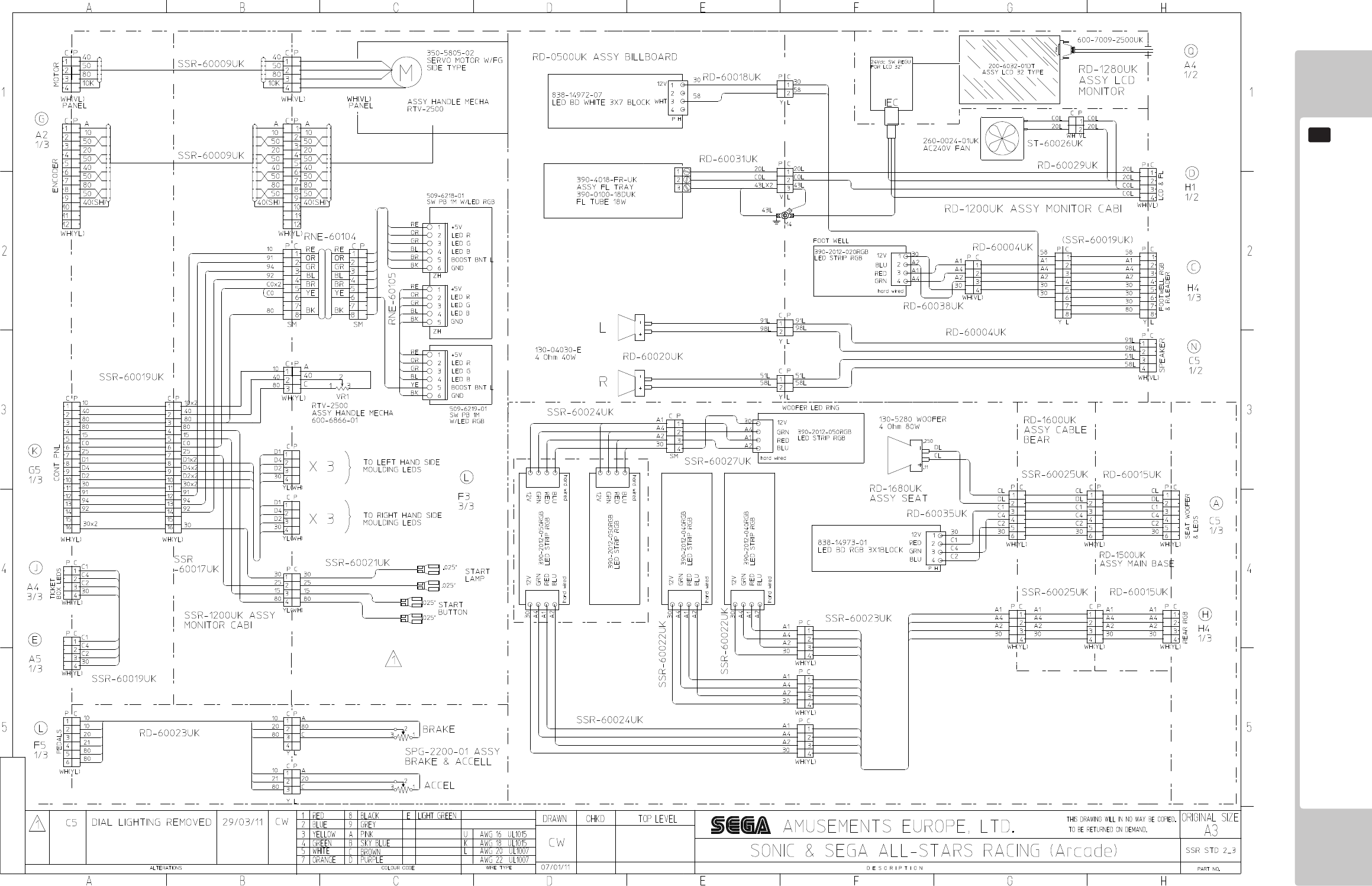
173
WIRING DIAGRAMS
21
(D-2/3)
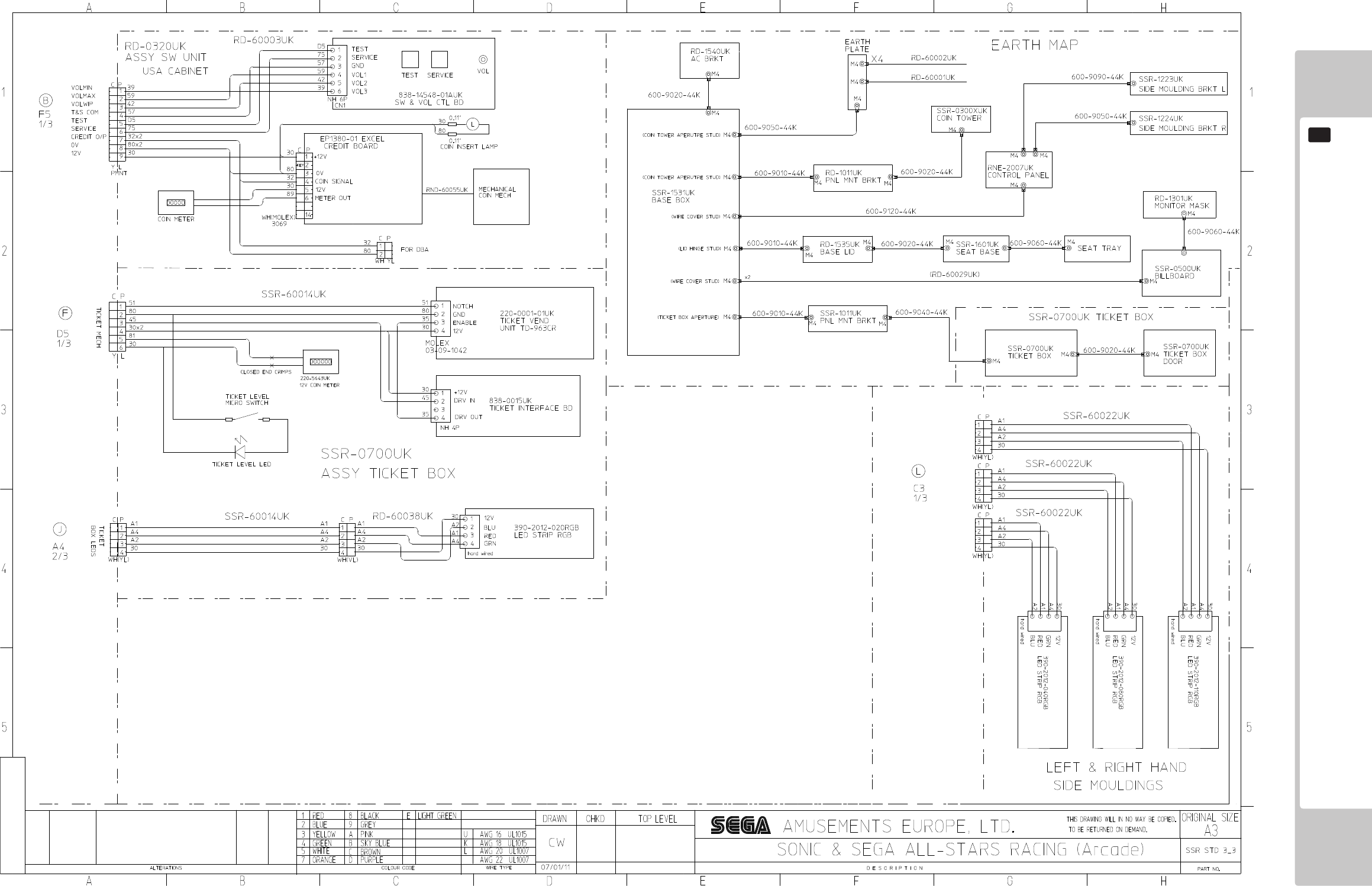
174
WIRING DIAGRAMS
21
(D-3/3)
