Arcade Star Wars Trilogy Ur Manual Stwur_ma User
stwur stwur
2013-11-27
User Manual: Arcade Star Wars Trilogy Ur Manual
Open the PDF directly: View PDF ![]() .
.
Page Count: 73

1st PRINTING JAN 99
MANUAL NO. 4201-6424-03
U/R VERSION
OWNER’S MANUALOWNER’S MANUAL
OWNER’S MANUALOWNER’S MANUAL
OWNER’S MANUAL
SEGA ENTERPRISES, INC. USA

Warranty
Your new Sega Product is covered for a period of 90 days from the date of shipment. This certifies
that the Printed Circuit Boards, Power Supplies and Monitor are to be free of defects in workman-
ship or materials under normal operating conditions. This also certifies that all Interactive Control
Assemblies are to be free from defects in workmanship and materials under normal operating condi-
tions. No other product in this machine is hereby covered.
Sellers sole liability in the event a warranted part described above fails shall be, at its option, to
replace or repair the defective part during the warranty period. For Warranty claims, contact your
Sega Distributor.
Should the Seller determine, by inspection that the product was caused by Accident, Misuse, Ne-
glect, Alteration, Improper Repair, Installation or Testing, the warranty offered will be null and void.
Under no circumstances is the Seller responsible for any loss of profits, loss of use, or other dam-
ages.
This shall be the exclusive written Warranty of the original purchaser expressed in lieu of all other
warranties expressed or implied. Under no circumstance shall it extend beyond the period of time
listed above.
VISIT OUR WEBSITE!

INTRODUCTION OF THE OWNERS MANUAL
GENERAL PRECAUTIONS
1. NAME OF PARTS
2. ACCESSORIES
3. ASSEMBLY AND INSTALLATION
4. PRECAUTIONS TO BE HEEDED WHEN MOVING MACHINE
5. CONTENTS OF GAME
6. EXPLANATION OF TEST AND DATA DISPLAY
6-1 SWITCH UNIT AND COIN METER
6-2 TEST MODE
6-3 MEMORY TEST
6-4 CALIBRATION TEST
6-5 FEEDBACK LEVER REACTION TEST
6-6 INPUT TEST
6-7 OUTPUT TEST
6-8 SOUND TEST
6-9 C.R.T. TEST
6-10 GAME ASSIGNMENTS
6-11 COIN ASSIGNMENTS
6-12 BOOKKEEPING
6-13 BACKUP DATA CLEAR
7. CONTROLLER
7-1 ADJUSTING/REPLACING THE VOLUME
7-2 GREASING
7-3 REPLACING THE SWITCH
8. COIN SELECTOR
9. PROJECTOR
9-1 CLEANING THE SCREEN
9-2 MITSUBISHI PROJECTOR
9-3 TOSHIBA PROJECTOR
10. REPLACING THE FLUORESCENT LAMP, AND LAMPS
10-1 REPLACEMENT OF FLUORESCENT LAMP
10-2 REPLACEMENT OF LAMPS
11. PERIODIC INSPECTION TABLE
12. TROUBLESHOOTING
13. GAME BOARD
13-1 REMOVING THE GAME BOARD
13-2 COMPOSITION OF THE GAME BOARD
13-3 DRIVE BOARD
14. DESIGN RELATED PARTS
15. PARTS LIST
16. WIRING DIAGRAMS
1
2~3
4
5~7
8~15
16
17~19
20~33
21
22
23
23~24
24
25
25
26
27
28
29~32
33
33
34~37
34~35
36
37
38~40
41~54
41
42~43
44~54
55~58
55~57
58
59
60~61
62~66
62~63
64
65~66
67~68
69~101
XXX
TABLE OF CONTENTS
1
SEGA ENTERPRISES, LTD., has for more than 30 years been supplying various innovative and
popular amusement products to the world market. This Owners Manual is intended to provide
detailed descriptions together with all the necessary installation, game settings and parts ordering
information related to the STAR WARS TRILOGY U/R, a new SEGA product.
This manual is intended for those who have knowledge of electricity and technical expertise, espe-
cially in ICs, CRTs, microprocessors, and circuit boards. Read this manual carefully to acquire
sufficient knowledge before working on the machine. Should there be a malfunction, non-technical
personnel should under no circumstances touch the interior system. Should the need arise, contact
our main office, or the closest branch office listed below.
SEGA ENTERPRISES, INC. (USA)
Customer Service
45133 Industrial Drive
Fremont, CA 94538
Phone 650-632-7580
Fax 650-632-7594
7:30 am - 4:00 pm, Pacific Standard Time
Monday thru Friday
INTRODUCTION OF THE OWNERS MANUAL
SPECIFICATIONS
Installation space: 36.9 in.(D) x 30.1 in.(W)
Height: 78.9 in.
Weight: Approx. 381.4 lbs.
Power maximum current: 3.22 Amps (AC 120V 60 Hz AREA)
MONITOR: 29” COLOR MONITOR

2
General Precautions
Follow Instructions: All operating and use instructions should be followed.
Attachments: Do not use attachments not recommended by the product manufacturer as they may cause hazards.
Accessories: Do not place this product on an unstable cart, stand, tripod, bracket, or table. The product may fall,
causing serious injury to a child or adult, and serious damage to the product. Use only with a cart, stand, tripod, bracket, or
table recommended by the manufacturer, or sold with the product. Any mounting of the product should follow the
manufacturer’s instructions, and should use only mounting accessories recommended by the manufacturer.
Moving the Product: This product should be moved with care. Quick stops, excessive force, and uneven surfaces
may cause the product to overturn.
Ventilation: Slots and openings in the cabinet are provided for ventilation, to ensure reliable operation of the product
and to protect it from overheating; these openings must not be blocked or covered. The openings should never be blocked
by placing the product in a built-in installation such as a bookcase or rack unless proper ventilation is provided or the
manufacturer’s instructions have been adhered to.
Power Sources: This product should be operated only from the type of power source indicated on the marking label.
If you are not sure of the type of power supply to your location, consult your local power company. For products intended
to operate from battery power or other sources, refer to the operating instructions.
Grounding or Polarization: This product is equipped with a three-wire grounding-type plug, a plug having a third
(grounding) pin. This plug will only fit into a grounding-type power outlet. This is a safety feature. If you are unable to
insert the plug into the outlet, contact your electrician to replace your obsolete outlet. Do not defeat the safety purpose of the
grounding-type plug.
Power Cord Protection: Power-supply cords should be routed so that they are not likely to be walked on or pinched
by items placed upon or against them, paying particular attention to cords at plugs, convenience receptacles, and the point
where they exit from the product.
Overloading: Do not overload wall outlets, extension cords, or integral convenience receptacles as this can result in
a risk of fire or electric shock.
Object and Liquid Entry: Never push objects of any kind into this product through openings as they may touch
dangerous voltage points or short-out parts that could result in a fire or electric shock. Never spill liquid of any kind on the
product.
Servicing: Do not attempt to service this product yourself as opening or removing covers may expose you to danger-
ous voltage or other hazards. Refer all servicing to qualified service personnel.
Damage Requiring Service: Unplug this product from the wall outlet and refer servicing to qualified service person-
nel under the following conditions:
a) If the power cord or plug is damaged;
b) If liquid has been spilled, or objects have fallen into the product;
c) If the product has been exposed to rain or water;
d) If the product does not operate normally when following the operating instructions. Adjust only those controls that
are explained in the operating instructions. An improper adjustment of other controls may result in damage and will
often require extensive work by a qualified technician to restore the product to its normal operation;
e) If the product has been dropped or damaged in any way;
f) When the product exhibits a distinct change in performance; this indicates a need for service.
Replacement Parts: When replacement parts are required, be sure the service technician has used replacements parts
specified by the manufacturer or that have the same characteristics as the original part. Unauthorized substitutions may
result in fire, electric shock, or other hazards.

3
Safety Check: Upon completion of any service or repairs to this product, ask the service technician to perform safety
checks to determine that the product is in proper operating condition.
Heat: The product should be situated away from heat sources such as radiators, heat registers, stoves, or other prod-
ucts (including amplifiers) that produce heat.
Lithium Battery- Dispose of batteries only in accordance with the battery manufacturer’s recommen-
dations. Do not dispose in an open flame condition, since the battery may explode.
Cleaning: When cleaning the monitor glass, use water or glass cleaner and a soft cloth. Do not apply chemicals such
as benzine, thinner, etc.
Location: This an indoor game machine, DO NOT install it outside. To ensure proper usage, avoid installing indoors
in the places mentioned below:
• Places subject to rain/water leakage, or condensation due to humidity;
• In close proximity to a potential wet area;
• Locations receiving direct sunlight;
• Places close to heating units or hot air;
•In the vicinity of highly inflammable/volatile chemicals or hazardous matter;
• On sloped surfaces;
• In the vicinity of emergency response facilities such as fire exits and fire extinguishers;
• Places subject to any type of violent impact;
• Dusty places.
INSTALLATION PRECAUTIONS
• Verify the amperage of the branch circuit outlet before plugging in the power plug. Do not over-
load the circuit.
• Avoid using an extension cord. If one is required, use an extension cord of type SJT, 16/3 AWG
rated min. 120 VAC, 7A.
• Moving this unit requires a minimum clearance (of doors, etc.) of 32” (W) by 77” (H).
• For the operation of this machine, secure a minimum area of 32” (W) by 42”(D).
REGULATORY APPROVALS
This game has been tested and found to comply with the Federal Communications Commission Rules.
This device complies with Part 15 of the FCC Rules. Operation is subject to the following two conditions: (1) This
device may not cause harmful interference, and (2) this device must accept any interference received, including interference
that may cause undesired operation.
This game has been tested and listed by Underwriters Laboratories, Inc., to ANSI/UL22.
LISTED
UL
®
5K92
AMUSEMENT MACHINE
4
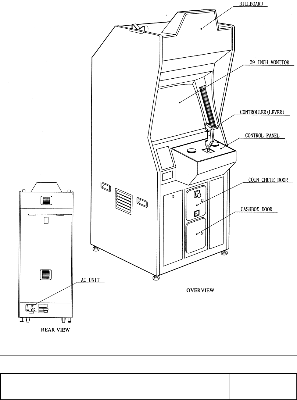
4. NAME OF PARTS
GAME SPECIFICATIONS WIDTH DEPTHHEIGHT WEIGHT
30” X 79” X 37” ~383 LBS.
CABINET U/R
WHEN ASSEMBLED
all measurements are rounded up to the nearest 0.5”
5
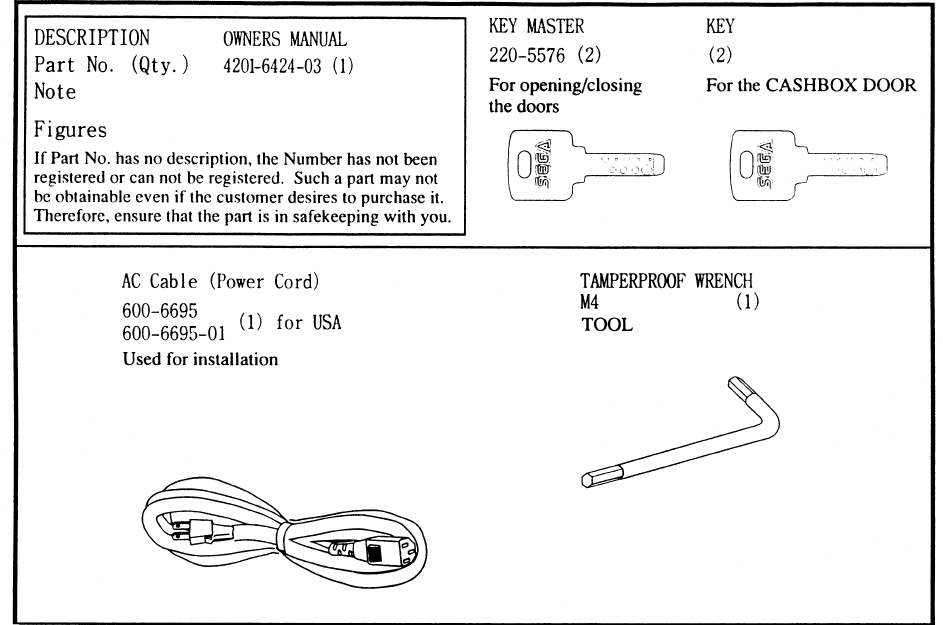
5. ACCESSORIES

6
“CHECK SIDE” Display
FILTER BOARD
CARTON BOX
601-8928 (1)
Used for transporting the GAME BOARD.
{SUPPLIED WITH YOUR GAME}
DO NOT SHIP GAME BOARD WITHOUT
THIS BOX AS IT MAY DAMAGE THE GAME
BOARD AND VOID YOUR WARRANTY.
!!NEVER SHIP MODEL 3 AND/OR NAMOI
!!NEVER SHIP MODEL 3 AND/OR NAMOI
GAME BOARDS OUTSIDE OF CAGE!!
GAME BOARDS OUTSIDE OF CAGE!!
THE SHIPMENT METHOD DESCRIBED BELOW ONLY
APPLIES TO ‘MODEL 3’ AND ‘NAOMI’ BOARDS
CONTAINED IN THE FOLLOWING GAMES:
NO OTHER GAMES BOARDS ARE TO BE SHIPPED IN THE CAGE AS
THEY MAY BE DAMAGED BEYOND REPAIR. PLEASE SHIP THEM
WITHOUT CAGE PROPERLY PROTECTED DURING SHIPPING.
LOST WORLD, VIRTUA FIGHTER 3, SUPER GT, SEGA BASS FISHING, STRIKER 2
HARLEY DAVIDSON, RALLY 2, DAYTONA 2, DIRT DEVILS, THE OCEAN HUNTER,
STAR WARS TRILOGY, HOUSE OF THE DEAD 2
- 9 -
7
3. ASSEMBLING PRECAUTIONS
Note that the tools such as a phillips screwdriver and wrench for M16 hexagon bolt w/24 mm width
across flats are required for the assembly work.
When carrying out the assembly work, follow the procedure in the following 4-item sequence:
INSTALLING THE BILLBOARD PLATE
SECURING IN PLACE
POWER SUPPLY
Assembling should be performed as per this manual. Since this is a
complex machine, erroneous assembling may cause damage to the
machine, or malfunctioning to occur.
When assembling, be sure to perform work by plural persons.
Depending on the assembly work, there are some cases in which
performing the work by a single person can cause personal injury or
parts damage.
1
2
3
4ASSEMBLING CHECK
8
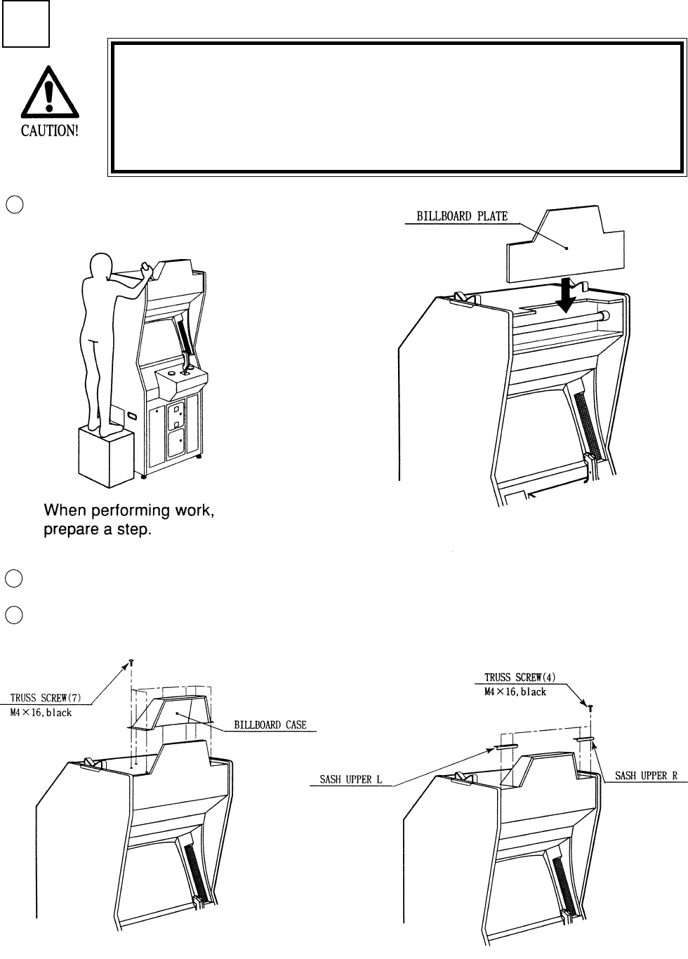
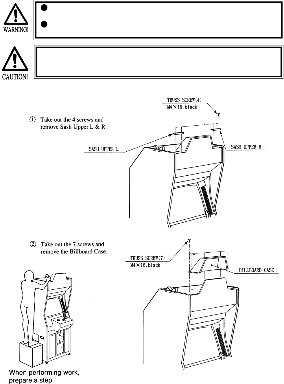
1INSTALLING THE BILLBOARD PLATE
Insert the BILLBOARD PLATE as shown.
Installing the Billboard by one person is difficult. Be sure to use
plural persons to perform the work safely and accurately.
To perform work safely and securely, be sure to prepare a step
which is in a stable and secure condition. Performing work without
using a step can cause a viloent falling down accident.
1
2
3
Install the BILLBOARD CASE with 7 screws.
Install the SASH UPPER L & R with 4 screws.
9
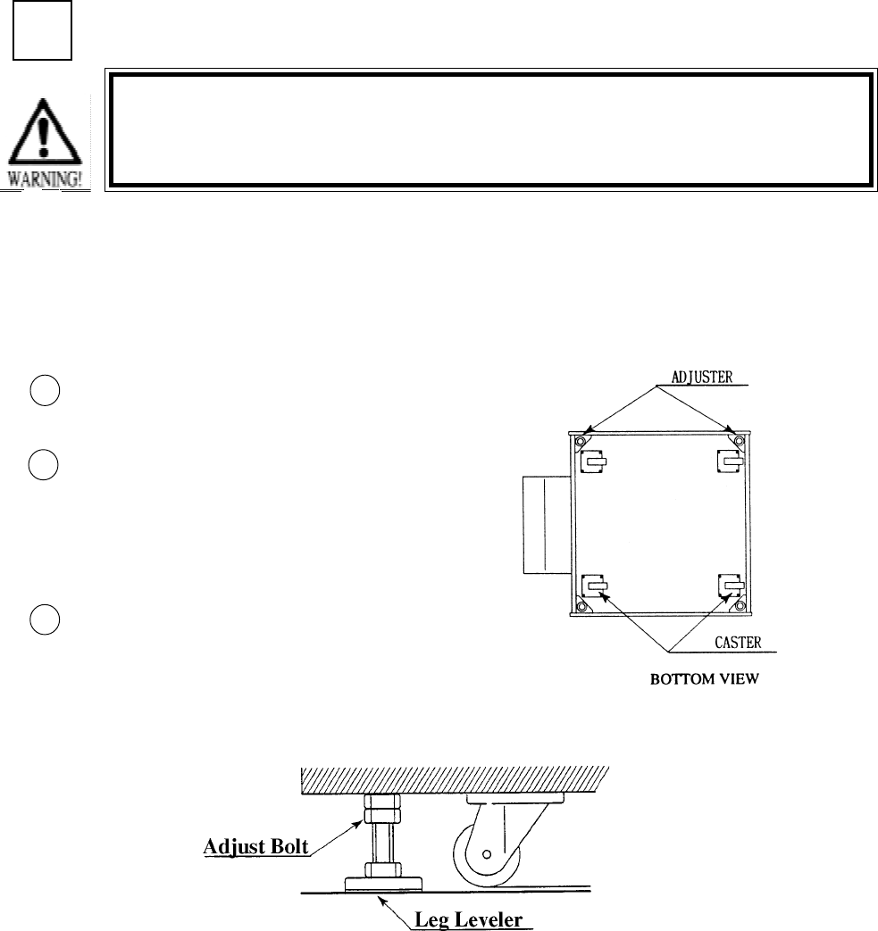
SECURING IN PLACE (ADJUSTER ADJUSTMENT)
Move the machine to the installation
position.
Cause all of the leg adjusters to make
contact with the floor. By using a
wrench, make adjustments in the height
of the leg adjusters to ensure that the
machine's position is level.
After making adjustments, fasten the
leg adjuster nut upward and secure the
height of the leg adjuster.
This machine has 4 each of casters and adjuster (See Below). When the installation position is
determined, cause the adjusters to come into contact with the floor directly, make adjustments in
a manner so that the casters will be raised approximately 5mm. from the floor and make sure that
the machine position is level.
Be sure to have all the Adjusters make contact with the floor surface.
Unless the Adjusters come into contact with the surface, the Cabinet
can move of itself, causing an accident.
3
2
1
2
10
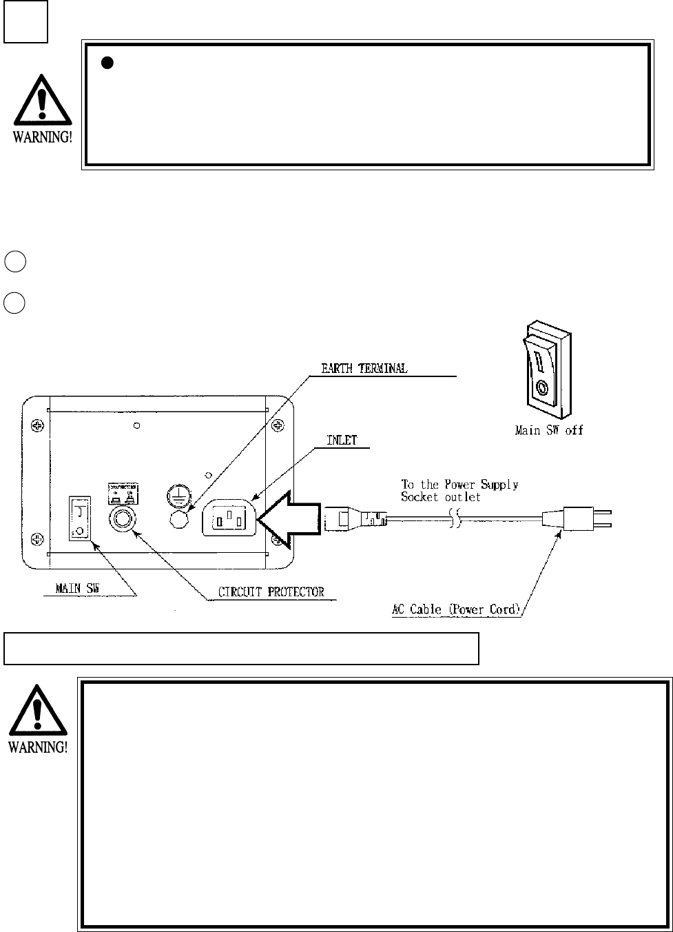
POWER SUPPLY
Ensure that the Main SW is OFF.
The AC unit is located on the left
side of the Cabinet. The Ac unit
incorporates the Main SW, and
power cord.
3
1
CAUTIONS TO BE HEEDED WHEN TURNING THE POWER ON
First make sure that no one is in the periphery of the bike body and turn
the Main SW on. When the power is turned on, the bike body motion
starts automatically. The presence of a person(s) in the periphery of the
bike can cause an accident. Turning the AC Unit’s Main SW on will cause
the machine to start the POWER ON check automatically. In the POWER
ON check, the bike body banks left and right, then returns to the center-
ing position and stops. During this check, do not touch the bike body. If
you do, the body reaction (at the time course-out or crashing) can not be
obtained correctly. The Advertise mode is displayed at the same time the
checking is finished. An ERROR display is indicated if irregularity is found
in the POWER ON check. In case of an irregular reaction during game,
turn power off and turn it back on again to finish the POWER ON check.
The AC unit is mounted on the left side of Front Cabinet DX. The AC Unit incorporates the Main
SW. Firmly insert the Power Plug into the Socket Outlet. Turn the Main SW ON to turn power
ON.
Ensure that the power cord is not exposed on the surface (passage,
etc.). If exposed, they can be caught and are susceptible to damage.
If damaged, the cord can cause an electric shock or short circuit.
Ensure that the wiring position is not in the customer's passage way
or the wiring has protective covering.
2
11
Selecting the INPUT TEST on the test mode
menu screen causes the screen (on which each
switch is tested) to be displayed. Press each
switch. For the coin switch test, insert a coin
into the coin inlet with the coin chute door
being open. If the display beside each switch
indicates "ON," the switch and wiring connec-
tions are satisfactory.
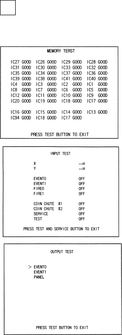
Selecting the MEMORY TEST on the test
mode menu screen causes the on-board
memory to be tested automatically. The game
board is satisfactory if the display beside each
IC No. shows GOOD.
In the TEST MODE, ensure that the assembly has been made correctly and IC BD is satisfactory
(refer to Section 6).
In the test mode, perform the following test:
ASSEMBLING CHECK
4
12
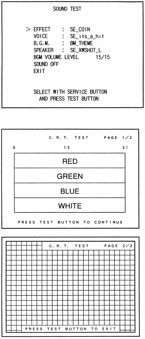
In the TEST mode, selecting SOUND TEST
causes the screen, on which sound related BD
and wiring connections are tested, to be
displayed. be sure to check if the sound is
satisfactorily emitted from each of speaker and
the sound volume is appropriate.
In the TEST mode menu, selecting C.R.T.
TEST allows the screen (on which the monitor
is tested) to be displayed. Although the monitor
adjustments have been made at the same time
of shipment from the factory, color deviation,
etc., may occur due to the effect caused by
geomagnitism, the location building’s steel
frames and other game machines in the periph-
ery. By watching the test mode screen, make
judgement as to whether an adjustment is
needed. If it is neccessary, adjust the monitor
by refering to Section 9.
13
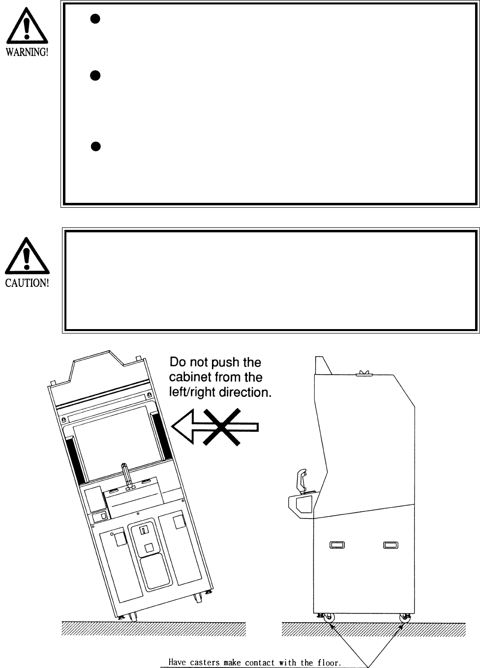
When moving the machine, be sure to pull out the plug from
the power supply. Moving the machine with the plug as is
inserted can damage the power cord and cause a fire or elec-
tric shock.
When moving the machine on the floor, retract the Adjusters
and ensure that Casters make contact with the floor. During
transportation, pay careful attention so that Casters do not
tread power cords. Damaging the power cords can cause an
electric shock and/or short circuit.
When lifting the cabinet, be sure to hold the catch portions or
bottom part. Lifting the cabinet by holding other portions can
damage parts and installation portions, due to the empty
weight of the cabinet, and cause personal injury.
Since this machine is a heavy structure of approximately 1000+lbs.
its leg adjusters should be retracted when moving the machine over
the floor. When moving the machine on the floor with slanted sur-
faces or step like differences, ensure that the PTV, Front Cabinet
and Rear Base are seperated. Lifting the Cabinet with those items as
is joined can cause the joint portions to be damaged.
4. PRECATIONS TO BE HEEDED WHEN MOVING THE MACHINE
14
5. CONTENTS OF GAME
The following explanations apply to the case the product is functioning satisfactoriliy. Should there be any moves
different from the following contents, some sort of faults may have occurred. Immediately look into the cause of the
fault and eliminate the cause thereof to ensure satisfactory operation.
The left/right lamps inside the Control Panel light up during game only.
The EVENT/START button (red buton, one each on the left/right side of LEVER) lights up in particular screens
only.
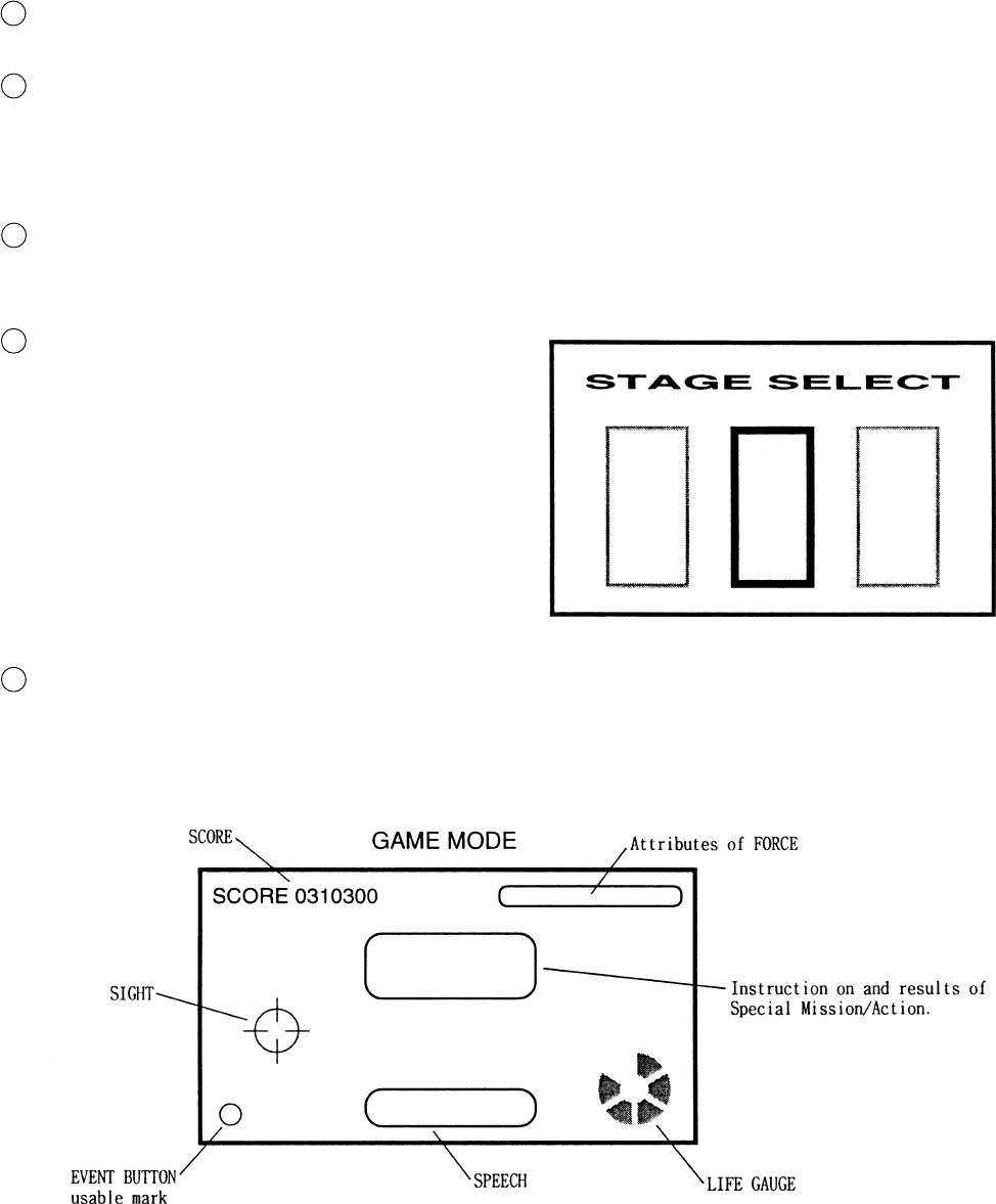
After inserting one play worth of coin(s), press the EVENT/START button to start, and the STAGE SELECT screen
appears.
At the time of starting the game, only the 3 stages, i.e., “YAVIN,” “HOTH,” and “ENDOR FOREST” are displayed.
By moving the LEVER left/right, select one from among the 3 stages and pull the trigger to decide. (execute the
selection).
NOTE: The player’s flight machine used during game is predetermined per STAGE.
After the STAGE is determined, the still screen for loading the game data appears for several seconds (this cannot
be skipped). Next, Movie Demo based on that particular STAGE’s story setting appears for several seconds (this
can be skipped by using the EVENT button).
During game, instruction on Special Mission/Action or hints on play may be displayed at the center of the screen.
The player can obtain good results by following the instruction.
During game, SPEECH sound may be emitted on the lower part of the screen. Although hints on play are included
sometimes, basically the SPEECH expressions are intended for presentation effects and do not affect game proceed-
ing.
1
2
3
4
5
Move the SIGHT by moving the LEVER up/down and left/
right, aim at the target and press either the trigger with the
forefinger or the thumbs switch with thumb to attack (the
function of the trigger at the position corresponding to the
forefinger and that of the Thumb SW. at the position
corresponding to a thumb identical). It is not necessary to
operate the flight machine. In the stage where the player
fights while boarding the flight machine, he can continu-
ally shoot by keeping the trigger pressed.
The up/down movements of the SIGHT as against the up/
down movements of LEVER can be set oppisite each other
within the TEST mode.
15
If the LIFE GAUGE on the lower right side of the screen is depleted, on-screen movements stop and CONTINUE
YES or NO is questioned. to continue, insert the necessary number of coins, select YES by moving the LEVER left/
right, and then press the EVENT/START button. In case the count becomes 0 (zero), or if NO is selected and
EVENT /START button is pressed, continue play is not possible. If CONTINUE is not selected, the present on-stage
results are displayed, then the game is over.
(On the still screen for CONTINUE confirmation, the background of screen may become red sometimes, but this is
only for presentation effects shown momentarily at the time of being subject to damage and does not mean any
irregularity. The status will be restored to the normal background at the same time game restarts.
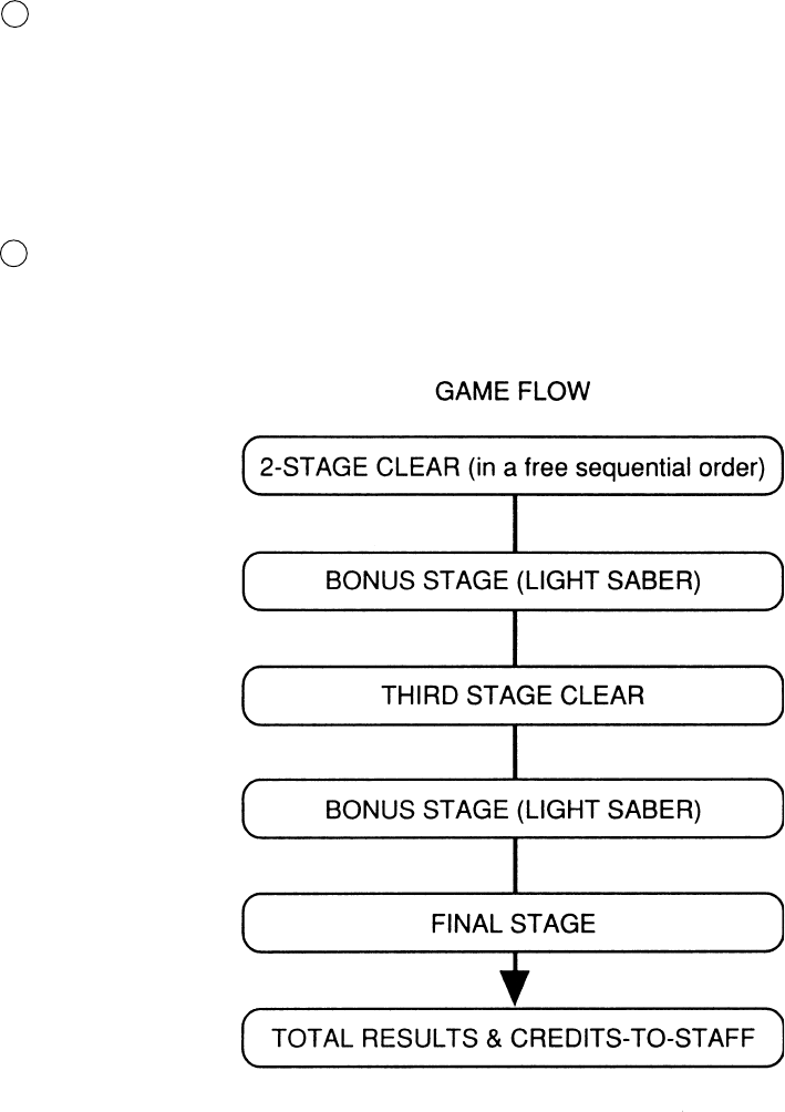
If all of the 3 STAGES shown at first in the STAGE SELECT screen are cleared, the 4th (FINAL) stage appears.
When all of the above stages are cleared, game results are shown and then credits-to-staff are displayed. Credits-to-
staff can skipped by using the EVENT/START button.
6
7
16
In a specific scene, the on-screen message may insruct you to press the EVENT button. Press
either the left/right EVENT buttons as these have the same function.
Even when no particular insruction is given, if a mark is indicated on the lower left side of the
screen, or when the Cabinet’s EVENT buton is lit, some sort of effects can be obtained (for
example, a covering fighter appears) by pressing the button. The type of the effects differs
depending on the specific scene and stage.
There will be no adverse effect on the proceeding of game play if the button is not pressed.
This feature is intended for enabling the player to enjoy playing the game better.
The features of FORCE vary in 6 catagories depending on the actions taken during the game,
and influence the performance of score, attack, and defense. Taking actions favorable to friends
(by saving them for example) causes LIGHT LEVEL to vary from 1 up to 3. On the contrary,
doing things unfavorable to friends (by attacking them for example) causes DARK LEVEL to
vary from 1 up to 3. The conditions of variation are not displayed in details. The features are
intended to allow players to enjoy playing game fully in depth.
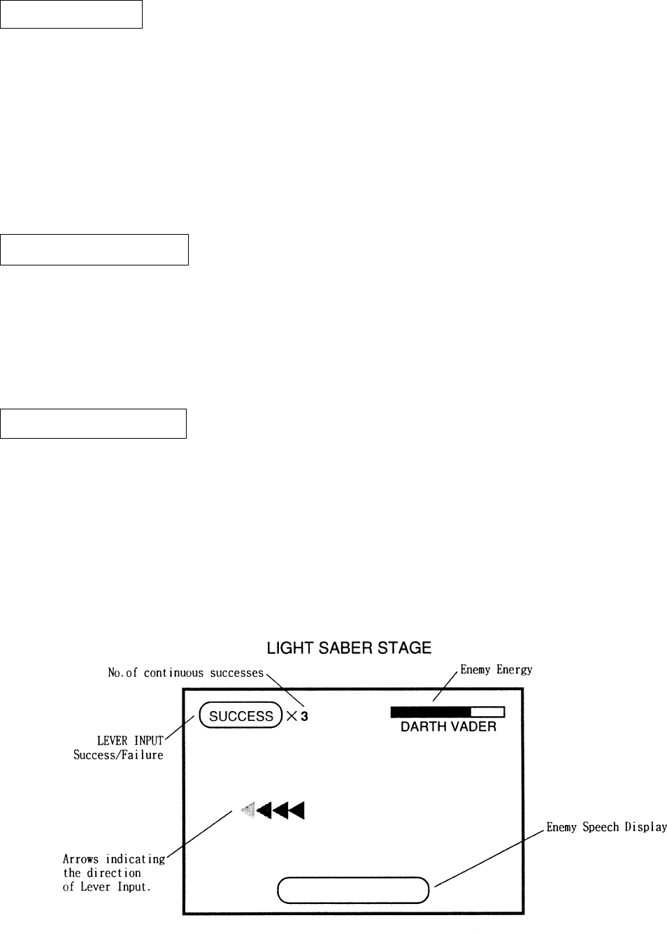
In the LIGHT SABER STAGE (a breif stage in which the player uses a LIGHT SABER), keep
inputting the Lever in the direction of the on-screen arrow to proceed with game play.
This is completely a BONUS STAGE and there will be no game over in the middle of play.
The LIGHT SABER STAGE appears once when 2 of the 3 stages are cleared in a free sequen-
tial order, and once again when the remaining stage is cleared. (Not displaying at the time of
game start).
EVENT BUTTON
ATTRIBUTES BUTTON
LIGHT SABER STAGE

17
By operating the switch unit, periodically perform the tests and data check. When installing
the machine initially or collecting cash, or when the machine does not function correctly,
perform checking in accordance with the explanations given in this section. The following
shows tests and modes that should be utilized as applicable.
INSTALLATION
OF MACHINE
6 - 4
2. In the INPUT TEST mode, check each SW and VR.
3. In the OUTPUT TEST mode, check each of lamps.
4. In the MEMORY TEST mode, check ICs on the IC Board.
Choose MEMORY TEST in the MENU mode to allow the
MEMORY test to be performed. In this test, PROGRAM
RAMs, ROMs, and ICs on the IC Board are checked.
Periodically perform the following:
1. MEMORY TEST
2. Ascertain each setting.
3. In the INPUT TEST mode, test the CONTROL device
4. In the OUTPUT TEST mode, check each of the lamps.
1. In the INPUT TEST mode, check each SW and VR.
2. Adjust or replace each SW and VR.
3.If the problem hasn’t been solved yet, check the CONTROL’s moves.
In the MONITOR ADJUSTMENT mode, check to see if the
PROJECTOR adjustment is appropriately made.
1. MEMORY TEST
2. In the SOUND TEST mode, check the sound related ROMs.
Check such data as game play time and histogram to adjust the
difficulty level, etc
1. Check to see that each setting is as per standard setting made
at the time of shipment.
PERIODIC
SERVICING
MEMORY
MONITOR
DATA CHECK
CONTROL
SYSTEM
6 - 8, 6 - 9,
6 - 10
6 - 4
6 - 7
6 - 3
6 - 3
6 - 8, 6 - 9
6 - 7
When the machine is installed, perform the following:
IC BOARD
6 - 4
7
6 - 3
6 - 3
TABLE 6 EXPLANATION OF TEST MODE
9
6 - 5
6 - 11
7
6. EXPLANATION OF TEST AND DATA DISPLAY
ITEMS DESCRIPTION SECTIONS
18
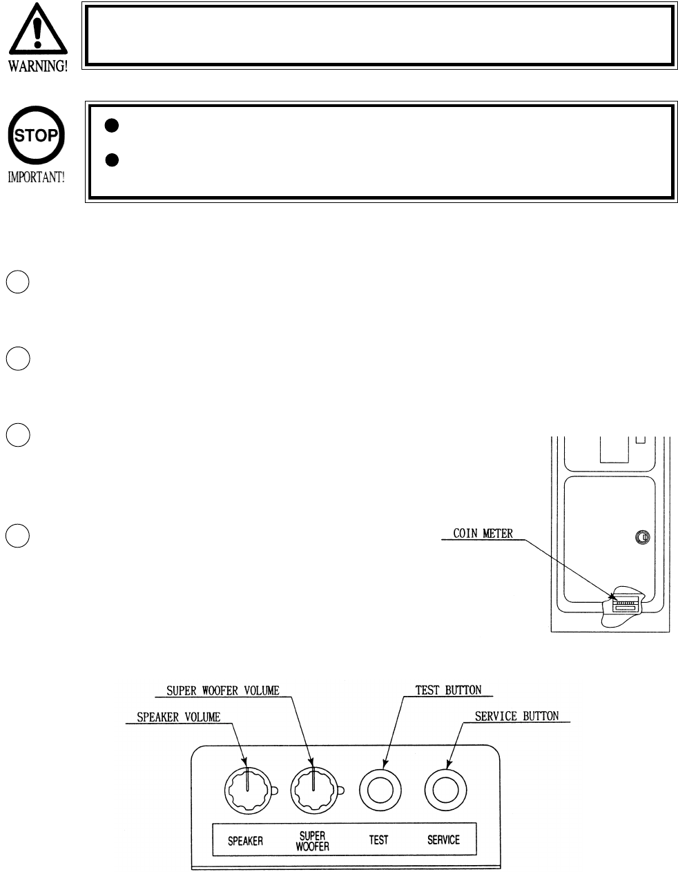
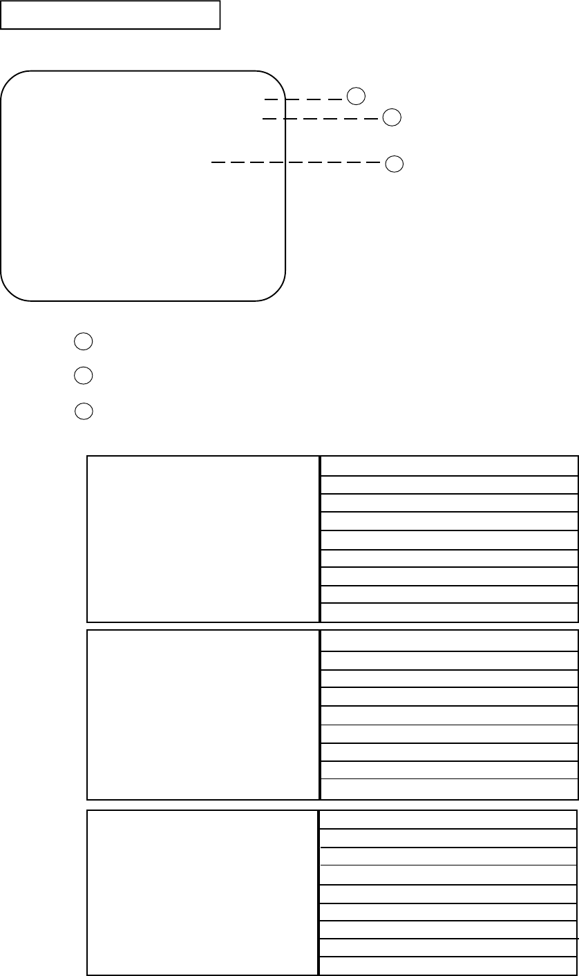
Open COIN CHUTE DOOR, and the switch unit shown appears. The function
of each switch is as follows:
6 - 1 SWITCH UNIT AND COIN METER
Never touch places other than those specified. Touching places not
specified can cause electric shock and short circuit.
Adjust to the optimum sound volume by considering the environmental
requirements of the installation location.
If the COIN METER and the game board are electrically disconnected,
game play is not possible.
SOUND VOLUME WOOFER
Controls the speaker volume only for
SEAT & BASE Woofer.
TEST BUTTON (TEST SW)
For the handling of the
TEST BUTTON,
refer to the section on test mode.
SERVICE BUTTON
(SERVICESW)
Gives credits without registering
on the coin meter.
2
1
3
SOUND VOLUME SPEAKER
Controls the speaker volume ofall of the machines
speakers.
4
19
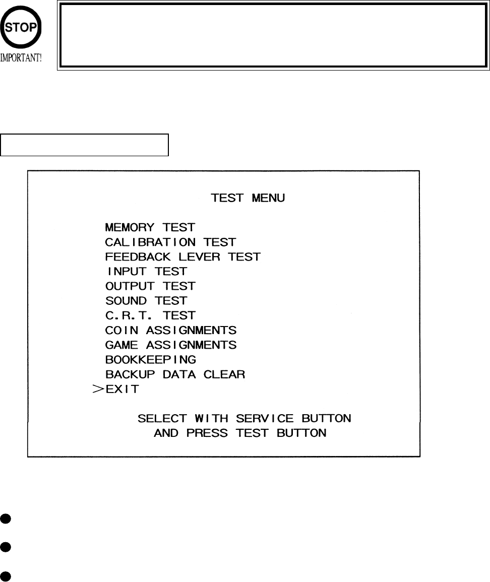
6 - 2 TEST MODE
SELECTION OF TEST ITEMS
In case settings are changed in GAME ASSIGNMENTS, COIN ASSIGNMENT the setting
changes are not effective unless the test mode is exited and the game mode returns
to the screen. The setting changes are ineffective if the power is turned off in the
test mode.
The TEST MODE allows the functioning of each part of the Cabinet to be checked, the monitor to
be adjusted, and the coins and game related various settings to be performed.
Press the TEST BUTTON to have the menu displayed on the screen.
Press the SERVICE BUTTON until the pointer is moved to the desired item to make a selection.
Bring the pointer to the desired item and press the TEST BUTTON to enter the selected item’s
test.
20
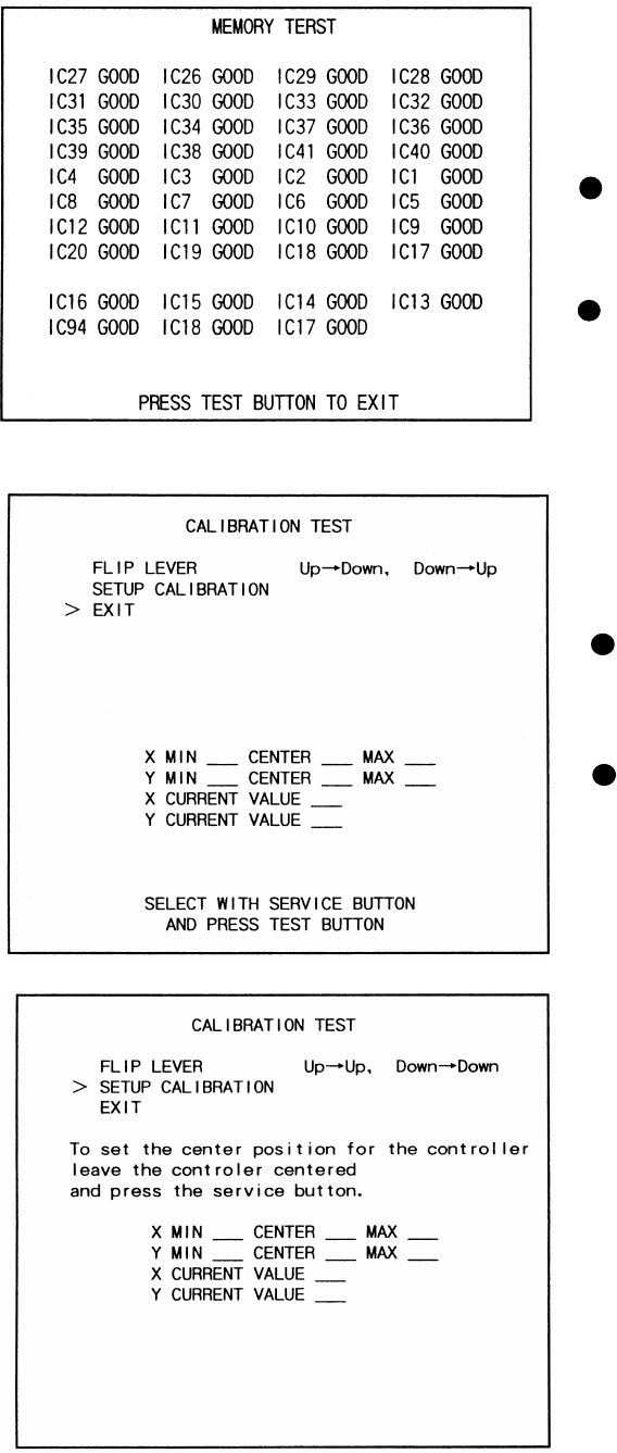
The MEMORY TEST mode is for checking the
on-BD memory IC functioning.
“GOOD” is displayed for normal ICs and
“BAD” is displayed for abnormal ICs
When the test is completed, if the
display is as shown left, it is
satisfactory.
After finishing the test, pressing the
TEST BUTTON allows the
MENU MODE to return on the
screen.
6 -3 MEMORY TEST
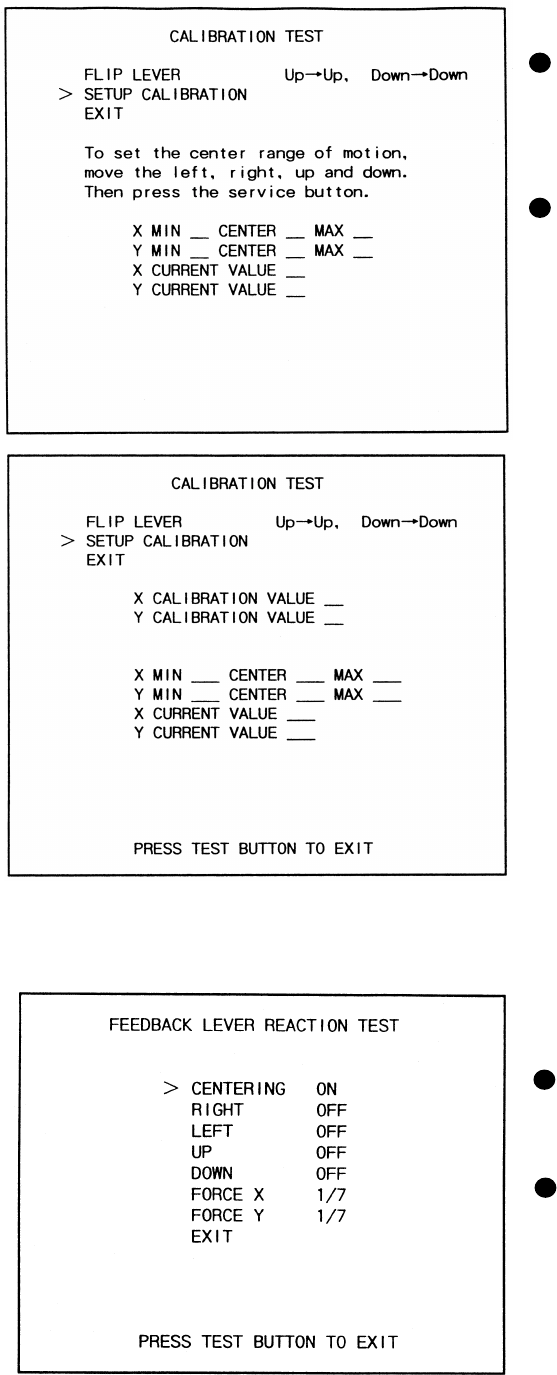
Selecting CALIBRATION TEST causes the
following screen to appear and allows the
CONTROLLER’s sight tobe set.
By pressing the SERVICE BUTTON,
move the arrow (>) to the desired test
item.
Press the TEST BUTTON to select test
item.
6 - 4 CALIBRATION TEST
21
FLIP LEVER
Used to intentionially reverse the move-
ments of SIGHT up/down as against
LEVER up/down.
SETUP CALIBRATION
Refer to the following screen and explana-
tions.
Move the arrow (>) to SETUP CALIBRA-
TION and then press the TEST BUTTON
to display the following message: “To set
the Center position for the controller, leave
the controller centered and press the
service button.”
Leave the Lever centered, press the service
button CALIBRATION TEST (3), move
the Lever fully up/down & left/right, and
then press the service button (CALIBRA-
TION(2)).
Select EXIT and press the TEST BUTTON
to returnt o the Menu Mode.
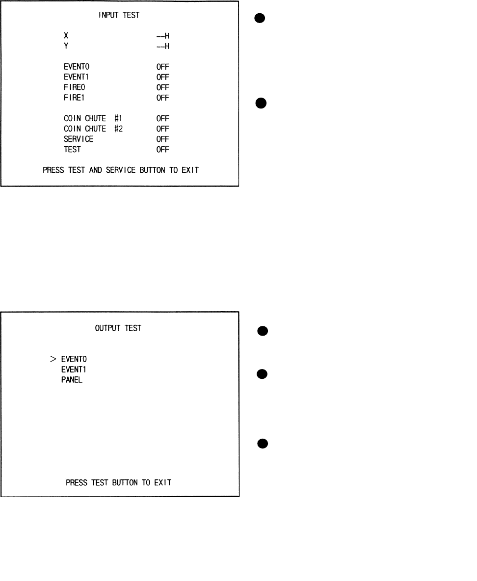
In this test, check the reaction of Controller
(lever).
CENTERING
This refers to the force to return the Lever
to the center.
FORCE X, FORCE Y
Allows for by-direction testing (up/down
and left/right)
Keep the Test Button pressed down to have
the Lever move automatically.
6 -5 FEEDBACK LEVER REACTION TEST
22
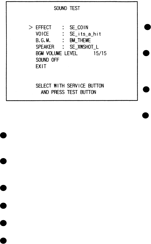
When INPUT TEST is selected, the MONITOR will show the following, allowing you
to watch the status of each switch.
On the screen, periodically check the status of each switch.
6 - 6 INPUT TEST
By pressing each switch, if the display
on the righthand side of the name of
each switch changes to ON from OFF,
the SW and the wiring connections are
satisfactory.
Open the COIN CHUTE DOOR and
insert a coin from the COIN ENRTY to
check the COIN CHUTE SW.
In the INPUT test, pressing the TEST
BUTTON causes the menu to return to
the screen.
Press the SERVICE BUTTON to move
the arrow to the desired lamp test item.
Press the TEST BUTTON. If the display
to the right of the lamp name changes to
ON from OFF, the lamp and wiring
connection are satisfactory.
Choose EXIT and press the TEST BUT-
TON to return to MENU mode (FIG. 6.2).
6 - 7 OUTPUT TEST
Choose OUTPUT TEST to have the MONITOR screen shown left to appear. This screen allows
lamp status to be checked.Periodically check the lamp status in this mode.
23
This enables sound used in the game to be
checked. Sound related memory and each
speaker are checked.
EFFECT:
Sound Effects during game.
VOICE:
Voice of annuocment and narration during
game.
B.G.M.:
Background music during game.
SPEAKER:
SE Speaker check.
6 - 8 SOUND TEST
BGM VOLUME LEVEL:
BGM sound level 0/15(low)~15/15(high).
SOUND OFF:
Output sound are all off.
Press the Service button and move the arrow to select the desired type.
Press the TEST button to have teh desired type of sound emitted.
Everytime the TEST button is pressed, the next sound is emitted.
To return to the MENU MODE, select EXIT and press the TEST button.
24
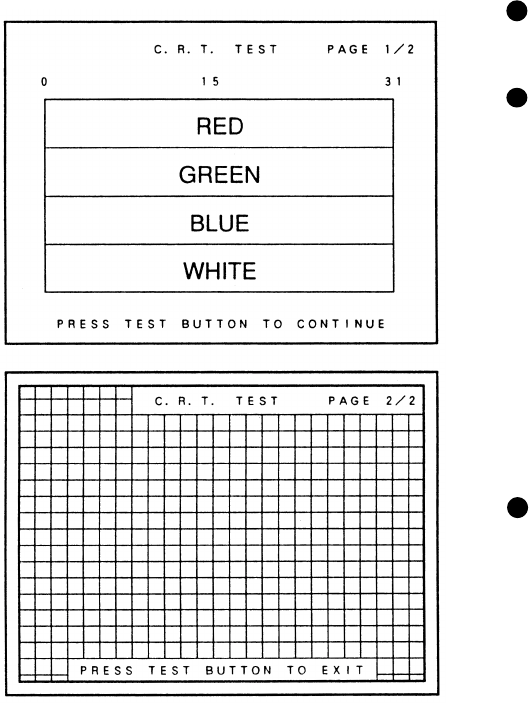
Select C.R.T. TEST to cause the MONI-
TOR to display the screen shown left,
allowing MONITOR adjustment status to
be checked.
Periodically check the MONITOR adjust-
ment status on this screen.
The screen (1/2) enables color adjustment
check to be performed. The color bar of
each of the 4 colors, i.e.,red, green, blue,
and white, is the darkest at the extreme left
and becomes brighter towards the extreme
right.
Press the TEST BUTTON to shift to the
next page (2/2).
The screen (2/2) allows screen size and
distortion to be tested.
Check if the CROSSHATCH FRAME
LINE goes out of the screen and if the
crosshatch lines are distorted.
Press the TEST BUTTON to return to the
MENU mode.
6 - 9 C.R.T. TEST
25
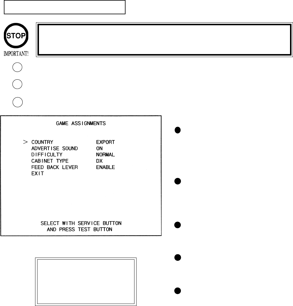
6 - 10 GAME ASSIGNMENTS
Selecting the GAME ASSIGNMENTS in the MENU mode causes the present game settings
to be displayed and also the game settings changes (game difficulty, etc.) can be made. Each
item displays the following content.
SETTING CHANGE PROCEDURE
Press the SERVICE BUTTON to move the arrow to the desired item.
Choose the desired setting change item by using the TEST BUTTON.
To return to the MENU mode, move the arrow to EXIT and press the TEST BUTTON.
1
2
GAME DIFFICULTY
This game allows by-course diffi-
culty level to be set in 4 levels.
Depending on the difficulty level
set, the intial time varies.
ADVERTISE SOUND
Setting of sound during Advertise.
ON(sound to be emitted),
OFF(sound not to be emitted).
CABINET TYPE
Setting of cabinet. Set to DELUXE
for this machine.
CONTROLLER REACTION
Sets the Controller’s vibration
strength and off for no vibration.
COUNTRY
Message language.
3
Setting changes cannot be stored unless the TEST BUTTON is pressed
while the arrow is on EXIT.
These FIGURES/These FIGURES/
These FIGURES/These FIGURES/
These FIGURES/
TABLES show theTABLES show the
TABLES show theTABLES show the
TABLES show the
factory recommendedfactory recommended
factory recommendedfactory recommended
factory recommended
settings.settings.
settings.settings.
settings.
26
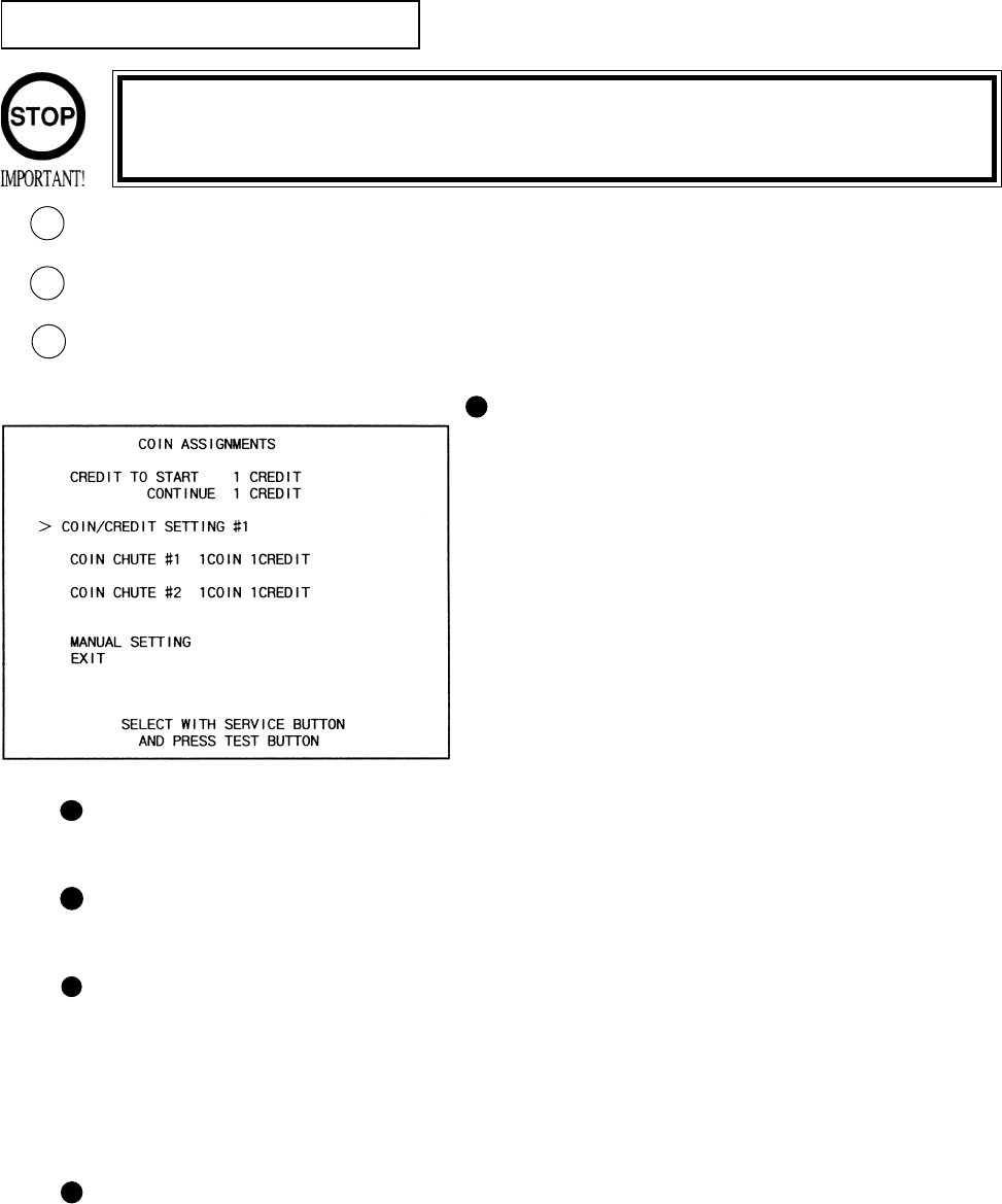
The “COIN ASSIGNMENTS” mode permits you to set the start number of credits, as well as
the basic numbers of coins and credits. This mode expresses “how many coins correspond to
how many credits.”
SETTING CHANGE PROCEDURE
Press the SERVICE BUTTON to move the arrow to the desired item.
Choose the desired setting change item by using the TEST BUTTON.
To return to the MENU mode, move the arrow to EXIT and press the TEST BUTTON.
COIN CHUTE TYPE
Sets the combination of the number of COIN
CHUTEs and the number of players as appli-
cable. In the case that the COIN CHUTE is
changed, be sure the setting is made in a manner
meeting the replaced coin chute.
COMMON:
Coins are accepted in common for both players.
INDIVIDUAL:
Each player uses a coin chute which accepts coins
independently.
6 - 11 COIN ASSIGNMENTS
CREDIT TO START
Number of credits required for starting game (1~5 credits are selected.)
CREDIT TO CONTINUE
Number of credits required for continuing game (1~5 credits are selected.)
COIN/CREDIT SETTING
Sets the CREDITS increase increment per coin insertion. There are 27 setings from #1 to
#27, expressed in XX CREDIT as against XX COINS inserted. (TABLE 6.10a, 6.10b) #27
refers to FREE PLAY.
When the COIN CHUTE TYPE is set to INDIVIDUAL, there are some setting numbers
not displayed as indicated in TABLE 6.10b.
MANUAL SETTING
This allows credit increase setting as against coin insertion to be further set in the manner
finer than COIN/CREDIT SETTING (refer to TABLE 6.10c).
1
2
3
Setting changes cannot be stored unless the TEST BUTTON is pressed
while the arrow is on EXIT.

27
TABLE 6.11a COIN/CREDIT SETTING (COIN CHUTE COMMON TYPE)
SETTING FUNCTIONING OF CHUTE#1
SETTING #1 1 COIN 1 CREDIT
SETTING #2 1 COIN 2 CREDITS
SETTING #3 1 COIN 3 CREDITS
SETTING #4 1 COIN 4 CREDITS
SETTING #5 1 COIN 5 CREDITS
SETTING #6 1 COIN 2 CREDITS
SETTING #7 1 COIN 5 CREDITS
SETTING #8 1 COIN 3 CREDITS
SETTING #9 1 COIN 4 CREDITS
SETTING #10 1 COIN 5 CREDITS
SETTING #11 1 COIN 6 CREDITS
SETTING #12 2 COINS 1 CREDIT
SETTING #13 1 COIN 1 CREDIT
SETTING #14 1 COIN 2 CREDITS
SETTING #15 1 COIN 1 CREDIT
2 COINS 3 CREDITS
SETTING #16 1 COIN 3 CREDITS
SETTING #17 3 COINS 1 CREDIT
SETTING #18 4 COINS 1 CREDIT
SETTING #19 1 COIN 1 CREDIT
2 COINS 2 CREDITS
3 COINS 3 CREDITS
4 COINS 5 CREDITS
SETTING #20 1 COIN 5 CREDITS
SETTING #21 5 COINS 1 CREDIT
SETTING #22 1 COIN 2 CREDITS
SETTING #23 2 COINS 1 CREDIT
4 COINS 2 CREDITS
5 COINS 3 CREDITS
SETTING #24 1 COIN 3 CREDITS
SETTING #25 1 COIN 1 CREDIT
2 COINS 2 CREDITS
3 COINS 3 CREDITS
4 COINS 4 CREDITS
5 COINS 6 CREDITS
SETTING #26 1 COIN 6 CREDITS
SETTING #27 FREE PLAY
28
SETTING FUNCTIONING OF COIN CHUTE
SETTING #1 1 COIN 1 CREDIT
SETTING #6 1 COIN 2 CREDITS
SETTING #8 1 COIN 3 CREDITS
SETTING #9 1 COIN 4 CREDITS
SETTING #10 1 COIN 5 CREDITS
SETTING #11 1 COIN 6 CREDITS
SETTING #12 2 COINS 1 CREDIT
SETTING #15 1 COIN 1 CREDIT
2 COINS 3 CREDITS
SETTING #17 3 COINS 1 CREDIT
SETTING #18 4 COINS 1 CREDIT
SETTING #19 1 COIN 1 CREDIT
2 COINS 2 CREDITS
3 COINS 3 CREDITS
4 COINS 5 CREDITS
SETTING #21 5 COINS 1 CREDIT
SETTING #22 3 COINS 1 CREDIT
5 COINS 2 CREDITS
SETTING #23 2 COINS 1 CREDIT
4 COINS 2 CREDITS
5 COINS 3 CREDITS
SETTING #25 1 COIN 1 CREDIT
2 COINS 2 CREDITS
3 COINS 3 CREDITS
4 COINS 4 CREDITS
5 COINS 6 CREDITS
SETTING #27 FREE PLAY
TABLE 6.11b COIN/CREDIT SETTING (COIN CHUTE INDIVIDUAL TYPE)
29
MANUAL SETTING
Selecting MANUAL SETTING in the COIN ASSIGNMENTS mode displays the following screen.
FIG. 6.11b MANUAL SETTING
BONUS ADDER NO BONUS ADDER
2 COINS GIVE 1 EXTRA COIN
3 COINS GIVE 1 EXTRA COIN
4 COINS GIVE 1 EXTRA COIN
5 COINS GIVE 1 EXTRA COIN
6 COINS GIVE 1 EXTRA COIN
7 COINS GIVE 1 EXTRA COIN
8 COINS GIVE 1 EXTRA COIN
9 COINS GIVE 1 EXTRA COIN
Table 6.11c MANUAL SETTING
Determines Coin/Credit setting.
This sets how many coins should be inserted to obtain one Service Coin.
This sets how many tokens one coin represents.
COIN TO CREDIT 1 COIN1 CREDIT
2 COINS 1 CREDIT
3 COINS 1 CREDIT
4 COINS 1 CREDIT
5 COINS 1 CREDIT
6 COINS 1 CREDIT
7 COINS 1 CREDIT
8 COINS 1 CREDIT
9 COINS 1 CREDIT
COIN CHUTE MULTIPLIER 1 COIN COUNTS AS 1 COIN
1 COIN COUNTS AS 2 COINS
1 COIN COUNTS AS 3 COINS
1 COIN COUNTS AS 4 COINS
1 COIN COUNTS AS 5 COINS
1 COIN COUNTS AS 6 COINS
1 COIN COUNTS AS 7 COINS
1 COIN COUNTS AS 8 COINS
1 COIN COUNTS AS 9 COINS
MANUAL SETTING
COIN TO CREDIT 1 COIN 1 CREDIT
BONUS ADDER NO BONUS ADDER
COIN CHUTE #1 MULTIPLIER
1 COIN COUNTS AS 1 COIN
COIN 1 2 3 4 5 6 7 8 9
CREDIT 1 2 3 4 5 6 7 8 9
COIN CHUTE #2 MULTIPLIER
1 COIN COUNTS AS 1 COIN
COIN 1 2 3 4 5 6 7 8 9
CREDIT 1 2 3 4 5 6 7 8 9
>EXIT
SELECT WITH SERVICE BUTTON
AND PRESS TEST BUTTON
1
2
3
3
1
2
30
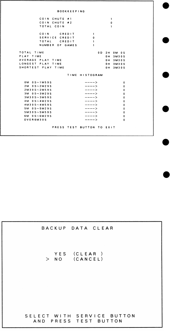
6 - 12 BOOKKEEPING
Choosing BOOKKEEPING in the MENU mode displays the data of operating status up to the
present are shown on 2 pages. Press the TEST BUTTON to proceed to PAGE 2/2.
COIN CHUTE#*:
Number of coins put in each Coin
Chute.
TOTAL COINS:
Total number of activations of Coin
Chutes.
COIN CREDITS:
Number of credits registered by
inserting coins.
SERVICE CREDITS:
Credits registered by the SERVICE
BUTTON.
TOTAL CREDITS:
Total number of credits (COIN
CREDITS+SERVICE CREDITS).
TOTAL TIME:
The total energized time.
6 - 13 BACKUP DATA CLEAR
Clears the contents of BOOKKEEPING
and high score player ranking entry.
When clearing, bring the arrow to “YES”
and when not clearing, to “NO”, by
using the SERVICE BUTTON, and push
the TEST BUTTON.
When the data has been cleared, “COM-
PLETED” will be displayed. Bring the
arrow to “NO” and press the TEST
BUTTON to cause the MENU mode to
return on to the screen.
Note that the contents of the game
setting and sighting adjustment are not
affected by BACKUP DATA CLEAR
operation.
31
This work should be performed by the locations Maitenance Man
or Service Man. Performing work by those who do not have the
technical expertise can cause electric shock accident.
7. CONTROLLER
Before starting to work, ensure that the power SW is OFF. Failure to
observe this can cause electric shock and short circuit accident.
Use care so as not to damage wirings. Damaged wiring can cause
electric shock and short circuit hazards.
Do not touch undesignated places. Touching places other than those
specified can cause electric shock and short circuit accidents.
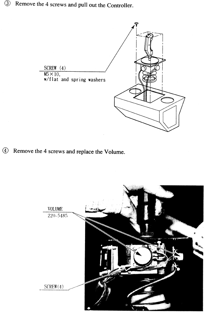
7 - 1 REPLACING THE VOLUME
32
33
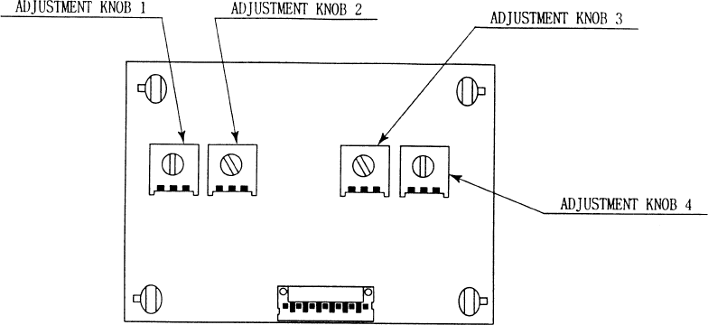
Remove the right-hand side plate, and the Amp BD appears on the upper left portion. Adjust the (CONTROL-
LER SIDE) ADJUSTMENT KNOB by using a ‘flat-blade’ driver.
ADJUSTMENT KNOB 1 (VR1):
Adjusts the center position in the UP/DOWN direction.
ADJUSTMENT KNOB 2 (VR2):
Adjusts the amplifying ration in the UP/DOWN direction.
ADJUSTMENT KNOB 3 (VR3):
Adjusts the amplifying ration in the RIGHT/LEFT direction.
ADJUSTMENT KNOB 4 (VR4):
Adjusts the center position in the RIGHT/LEFT direction.
ADJUSTMENT EXAMPLE: First, cause the INPUT TEST screen to appear.
1.) Set Adjustment Knob (VR1)~(VR4) to the center position.
2.) Facing the Y Axis (up/down direction), bring the Lever to the top limit and move VR2 to make adjustment
within the range of 30~3F.
3.) Bring the Lever to the lower limit, move the VR1 to make adjustment within the range of C0~CF. Repeat
procedure (2) and (3) several times and make adjustments within the range of the top limit of 30~3F and the
lower limit of C0~CF.
4.) Facing the X Axis (left/right direction), incline in the lever to the extreme right-hand end and move VR4 to
make adjustment within the range of 30~3F.
5.) Incline the Lever to the extreme left-hand side and move VR3 to make adjustment within the range of
C0~CF. Repeat procedure (4) and (5) sevral times and make adjustment wihtin th erange of right-hand limit of
30~3F and the left-hand limit of C0~CF.
7 - 2 AMP BD ADJUSTING METHOD
34
Do not touch places other than those specified. Touching places
not specified can cause an electric shock or short circuit accident.
Be sure to use the designated grease. Using undesiganted grease
can cause parts damage.
Do not apply greasing to undesignated places. Failure to observe
this can cause malfunctioning or quality deterioration of parts.
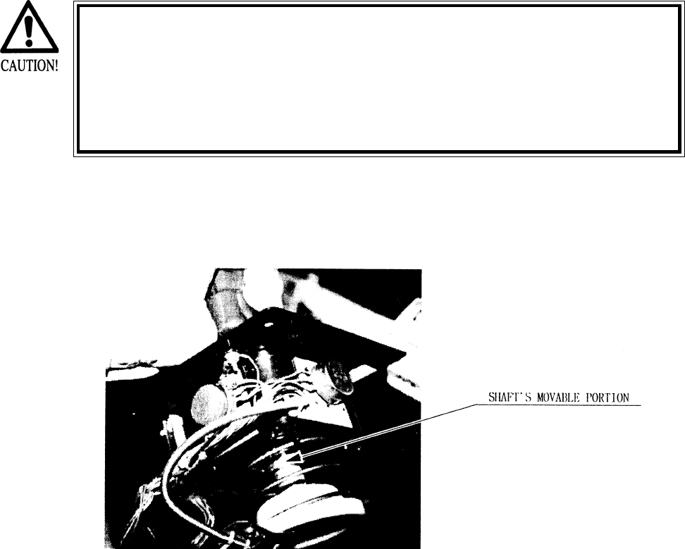
Apply spray greasing once every 6 months to the 2 places shown in the figure below, where
the spring and gear are engaged. For spray grease, use NOK KLUBER L60 or GREASE MATE.
7 - 3 GREASING
35
The Controller has some small parts. When dissassembling, be very
careful so as not to lose parts.
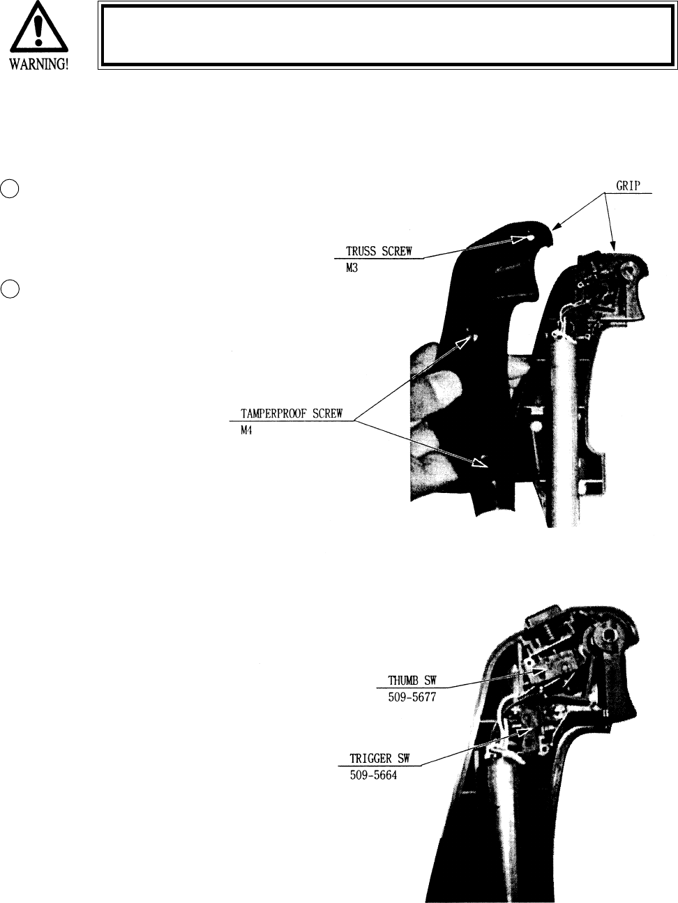
7 - 4 REPLACING THE SWITCH
When the Trigger SW is pushed, if the INPUT TEST screen does not display “ON”, the switch
inside the GRIP may be malfunctioning and in this case, switch replacement is needed.
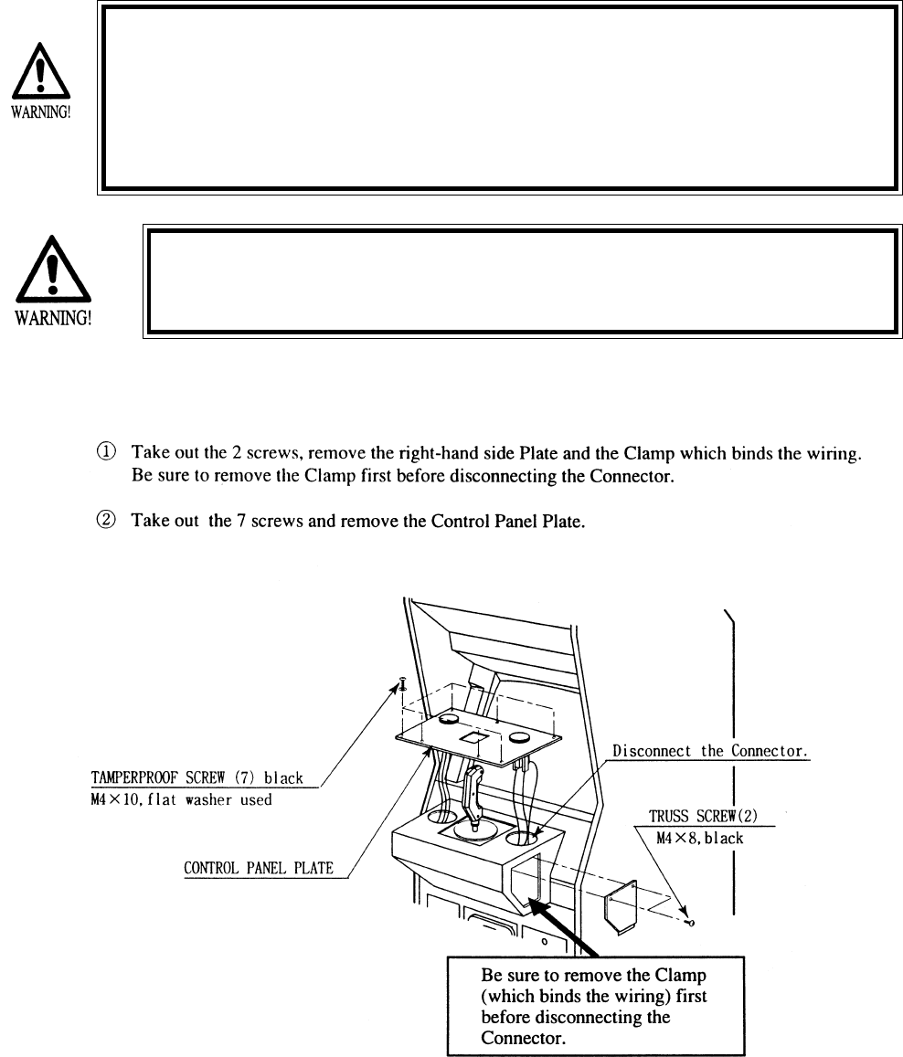
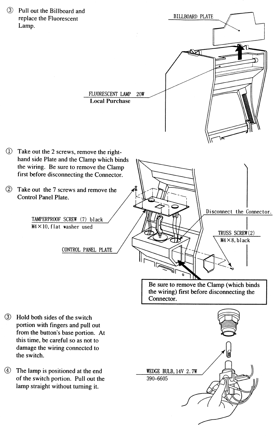
Remove the screw and disassemble the GRIP
Replace the Switch.
1
2
36
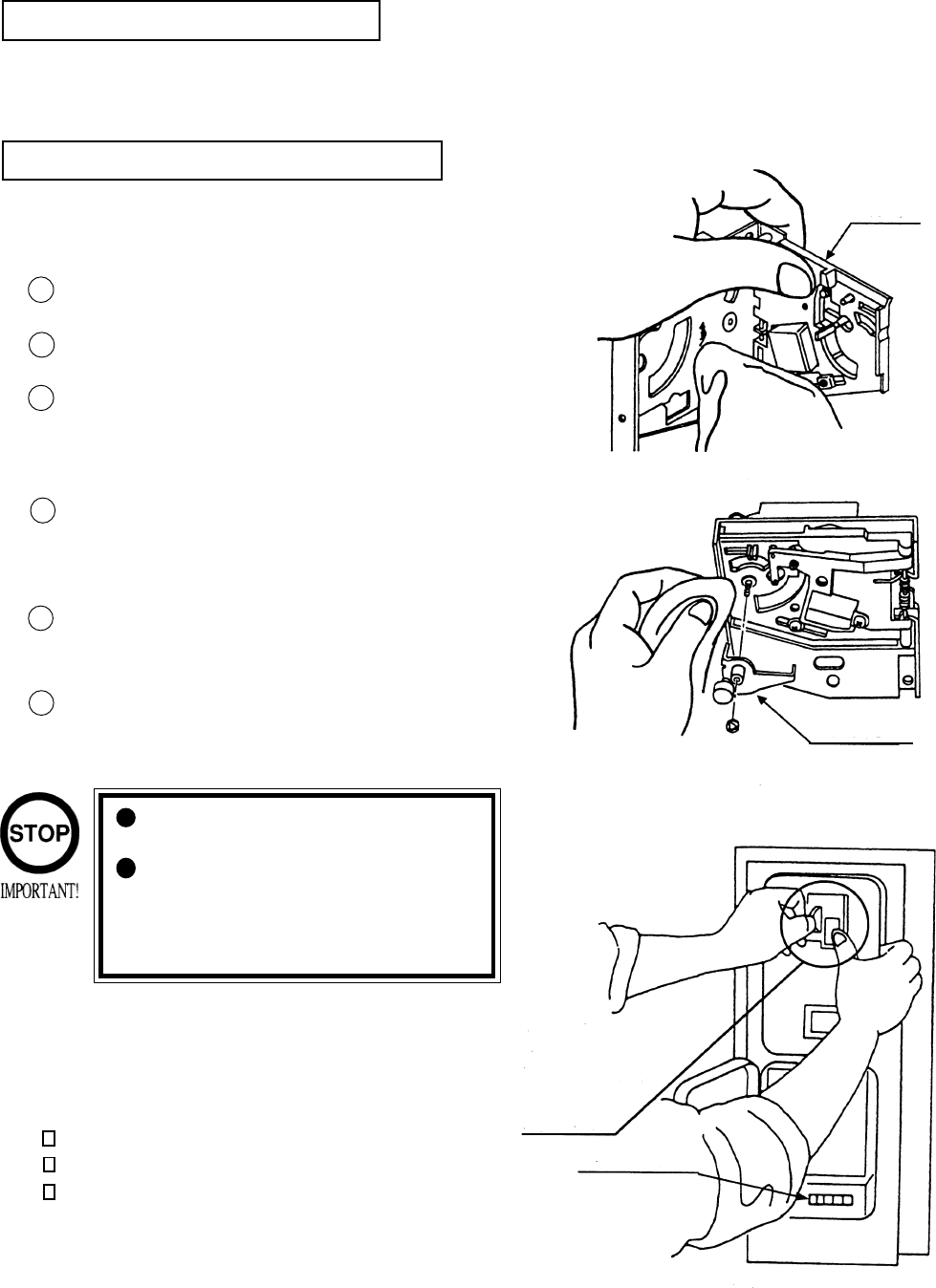
The coin selector should be cleaned
once every 3 months. When cleaning,
follow the procedure below:
Turn the power for the machine OFF.
Open the coin chute door.
Open the gate and dust off by using a
soft brush (made of wool, etc.).
Remove and clean smears by using a
soft cloth dipped in water or diluted
chemical detergent and then squeezed
dry.
Remove the CRADLE.
When removing the retaining ring(E-
ring), be very careful so as not to bend
the shaft.
Remove stain from the shaft and pillow
portions by wiping off with a soft cloth,
etc.
After wiping as per #5 above, further
apply a dry cloth, etc. to cause the coin
selector to dry completely.
Once a month, when performing the COIN SW
TEST, simultaneously check the following:
Does the Coin Meter count satisfactorily?
Does the coin drop into the Cashbox correctly?
Is the coin rejected when inserted while keeping
the REJECT BUTTON pressed down?
If the coin is not rejected when the REJECT BUTTON is pressed, open the coin chute door
and open the selector gate. After removing the jammed coin, put a normal coin in and check
to see that the selector correctly functions.
1
2
3
4
5
6
COIN INSERTION TEST
HANDLING THE COIN JAM
CLEANING THE COIN SELECTOR
8. COIN SELECTOR
Never apply machine oil, etc. to
the coin selector
After cleaning the Coin Selecting,
Insert a regular coin in the normal
working status and ensure that
the Selector correctly functions.
GATE
FIG. 8a
FIG.8b
COIN METER
FIG. 8c
CRADLE
Insert a coin
while keeping
the Reject
Button pressed
down and check
if it is
rejected.
37
OPTIONAL DOLLAR BILL ACCEPTOR
THE COIN DOOR ASSEMBLY USED ON STAR WARS TRILOGY U/R STAR WARS TRILOGY U/R
STAR WARS TRILOGY U/R STAR WARS TRILOGY U/R
STAR WARS TRILOGY U/R
COMES EQUIPPED TO ACCEPT A DOLLAR BILL ACCEPTOR. ALL
NEEDED WIRING CONNECTIONS ARE CONVIENENTLY LOCATED INSIDE
THE GAME FOR THIS APPLICATION.
THE COIN DOOR CAN ACCCOMMODATE THE FOLLOWING
VALIDATORS:
HOLE POSITION#1 MARS 2000 SERIES
(FORWARD-MOST POSITION)
HOLE POSITION#2 MARS 2000 SERIES
DBV45 (JCM)
HOLE POSITION #3 CURRENTLY NOT USED
HOLE POSITION #4 DSI01*
*The back flange on the chute can be removed for hole position #4.
If the flange is not removed, it may interfere with the back of the
cabinent.
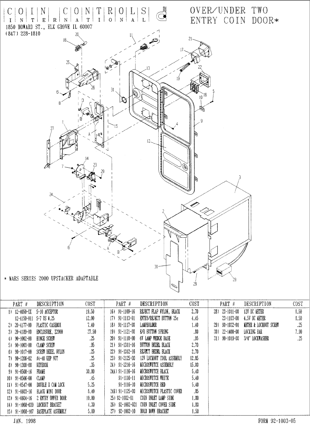
The frame and cashbox enclosure on this coindoor has been modified to accomodate a Mars 2000
series upstacker. A 2000 series stacker can be added by simply removing the top two entry door and
replacing it with a one entry door with a cut-out for a stacker. This one entry door can be ordered
through Coin Controls or one of Coin Controls authorized distributors. The Part # is 91-4000-01.
The Mars stacker can be obtained through an authorized Mars distributor.
38
39
9. MONITOR
When performing such work as installing and removing the monitor, inserting and disconnect-
ing the external connectors to and from monitor, be sure to disconnect the power connector
(plug) before starting work. Proceeding the work without following this instruction can cause
electric shock of malfunctioning.
Using the monitor by converting it without obtaining a prior permission is not allowed. SEGA
shall not be liable for any malfunctioning and accident caused by said conversion.
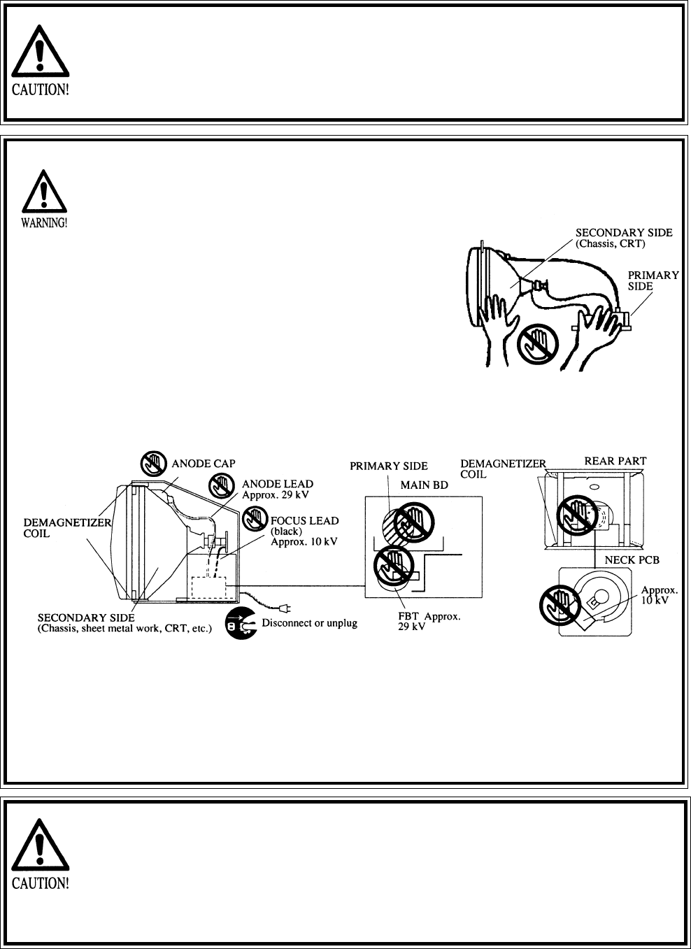
Primary side and secondary sidePrimary side and secondary side
Primary side and secondary sidePrimary side and secondary side
Primary side and secondary side
The monitor’s circuit which is divided into the Primary
side and secondary side, is electrically isolated. Do
not touch the primary side and the secondary side
simultaneously. Failing to observe the instruction can
cause electric shock, and this is very dangerous.
When making monitor adjustments, use a non-
conductive driver and make adjustment without
touching any other part other than the Adjustment
V.R. and Knob. Also, be sure not to cause a short-
circuit to the Primary side and the Secondary side. If
short-circuited, it can cause electric shock or mal-
functioning, which is very dangerous.
High tension VoltageHigh tension Voltage
High tension VoltageHigh tension Voltage
High tension Voltage
Some of the parts inside the monitor are subject to high-tension voltage in excess of 20,000
volts and very dangerous. Therefore, do not touch the monitor interior. Should soldering &
paper wastes, etc. be mixed in the monitor, turn the power off so as not to cause malfunc-
tioning or fire hazard.
Connecting the CRT and PCBConnecting the CRT and PCB
Connecting the CRT and PCBConnecting the CRT and PCB
Connecting the CRT and PCB
For combining the CRT and PCB, use the specified part No. to maintain the status of adjust-
ments made at the factory. The anode of the CRT itself will be accumulitavely charged as time
elapses, generating high tension voltage which is very dangerous. The monitor should be used
with the Chassis, CRT and PCB assembled. When repair, etc. is required at the time of malfunc-
tioning, be sure to send it in an “as assembled” condition. If these are disassembled, what’s
charged to said high tension voltage can be discharged, causing a very hazardous situation.
Therefore, under no circumstances should it be disassembled.
Static ElectricityStatic Electricity
Static ElectricityStatic Electricity
Static Electricity
Touching the CRT surface sometimes causes you to slightly feel electricity. This is because the
CRT surfaces are subject to static and will not adversly affect the human body.
Installation and removalInstallation and removal
Installation and removalInstallation and removal
Installation and removal
Ensure that the Magnetizer Coil, FBT (Fly-Back Transformer), Anode Lead and Focus Lead are
not positioned close to the sheet metal work’s sharp edges, etc. and avoid damaging the
insulated portions so as not to cause an electric shock and malfunctioning. (For the name of
parts, refer to the above figures.)
40
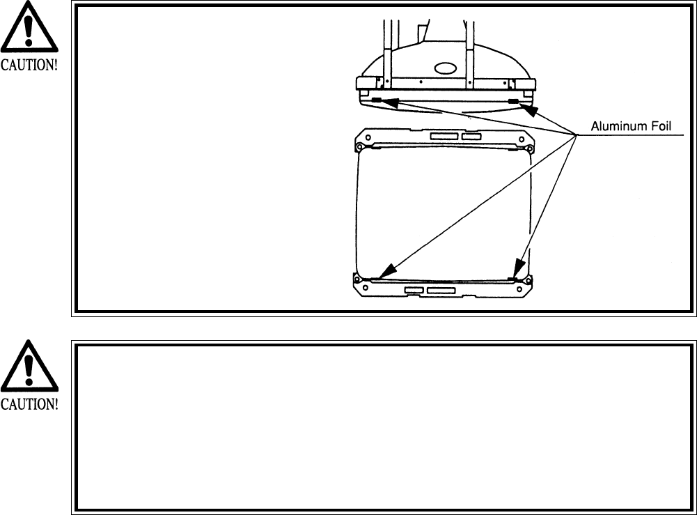
For the purpose of static prevention,
special coating is applied to the CRT
face of this product. To protect the
coating, pay attention to the following
points. Damaging the coating film can
cause electric shock to the customers.
For the caution to be heeded when
clearing, refer to the Section of Periodic
inspection Table.
Do not apply or rub with a hard item (a
rod with pointed edge, pen, etc.) to or
on C.R.T. surfaces.
Avoid applying stickers, seals, etc. on
the C.R.T. face.
Do not remove aluminum foils from the
C.R.T. corners. Removing the aluminum
foils can cause static prevention effects
to be lowered.
Monitor adjustments have been made at the time of shipment. There-
fore do not make further adjustment without a justifiable reason.
Adjusting the monitor which contains high tension parts is dangerous
work. Also, an erroneous adjustment can cause deviated synchroniza-
tion and image fault, resulting in malfunctioning.
When making adjustment, utilize a resinous Alignment Rod. Servicing
with bare hands or using conductive tools can cause electric shock.
41
42
10. REPLACEMENT OF FLUORESCENT LAMP AND LAMPS
When performing the work, be sure to turn power off. Working with
power on can cause an electric shock or short circuit accident.
The Flourescent Lamp, when it gets hot, can cause burns. Be very
careful when replacing the Fluorescent Lamp.
To perform work safely and securely, be sure to prepare a step which is in a
secure and stable condition. Not using a step or using an unstable step can
cause a violent falling down accident.
10 - 1 REPLACING THE FLUORESCENT BULB
43
10 - 2 REPLACING THE LAMPS
44
The items listed below require periodic check and maintenance to retain the performance of
this machine and ensure safe operation.
When handling the controller, the player will be in direct contact with it. In order to always
allow the player to enjoy the game, be sure to clean it regularly.
11. PERIODIC INSPECTION TABLE
Be sure to check once a year to see if Power Cords are damaged,
the plug is securley inserted, dust is accumulated between the
Socket Outlet and the Power Plug, etc. Using the product with
dust as is accumulated can cause a fire or electrical shock.
Periodically once a year, request the place of contact herin stated
or the Distributer, etc. where the product was purchased from, as
regards the interior cleaning. Using the product with dust as is
accumulated in the interior without cleaning can cause a fire or
accident. Note that cleaning the interior parts can be performed
on a pay-basis.
CLEANING CABINET SURFACES
When the cabinet surfaces are badly soiled, remove stains with a soft cloth dipped in water or
diluted (with water) chemical detergent and squezzed dry. To avoid damaging surface finish,
do not use such solvents as thinner, benzine, etc. other than ethyl alcohol, or abrasives,
bleaching agent and chemical dustcloth.
ITEMS DESCRIPTION PERIOD REFERENCE
CONTROL MECHA Check Volume Value and SW as required
Grease to gear portion Weekly 6
Check Adj. Gear engagement Monthly 6
COIN SELECTOR Check COIN SW Monthly 6
COIN SELECTOR cleaning Trimonthly 8
MONITOR SCREEN cleaning Weekly 9
Check adjustments Monthly 3, 6, 9
GAME BD Setting check monthly 6
INTERIOR Cleaning Annually see above.
POWER PLUG Inspection and cleaning
CABINET SURFACE Cleaning As necessary see below
CABINET Ensure that adjusters are
in contact with the floor As necessary 3
45
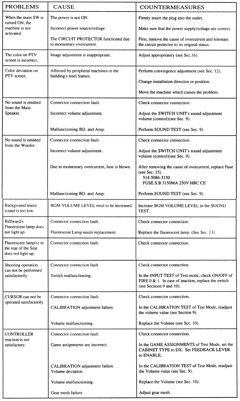
12. TROUBLESHOOTING
Should trouble occur, first check connector connections.
46
In case fuse replacement other than those stated inthis manual
are neccessary, contact where you purchased the product from
for inquires regarding this manner.
Fuse replacement other than those specified can cause hazards
and are strictly forbidden.
In order to prevent an electric shock, be sure to turn power off
and unplug from the socket outlet before performing work by
touching the internal parts of the product.
Be careful so as not to damage wirings. Damaged wiring can
cause electric shock and short circuit hazards.
Be sure to use fuses meeting the specified rating. Using fuses
exceeding the specified rating can cause of the fire and electric
shock hazards.
After eliminating the cause of the blowing of fuse, replace the
fuse. Depending on the cause of fuse blowing, continued use with
fuse as is blown can cause generation of heat and fire hazard.
47
13. GAME BOARD
In order to prevent an electrical shock, be sure to turn power off before
performing work by touching the interior parts of the product.
Be careful so as not to damage wirings. Damaged wiring can cause an
electric shock or short circuit accident.
Do not expose the Game BD, etc. without a good reason. In this product,
setting changes are made during the test mode. The Game BD need not be
operated. Use the Game BD, etc. as is with the same setting made at the
time of shipment. The electronic parts on the IC Board could be damaged
due to human static electricity.
13 - 1 GAME BOARD
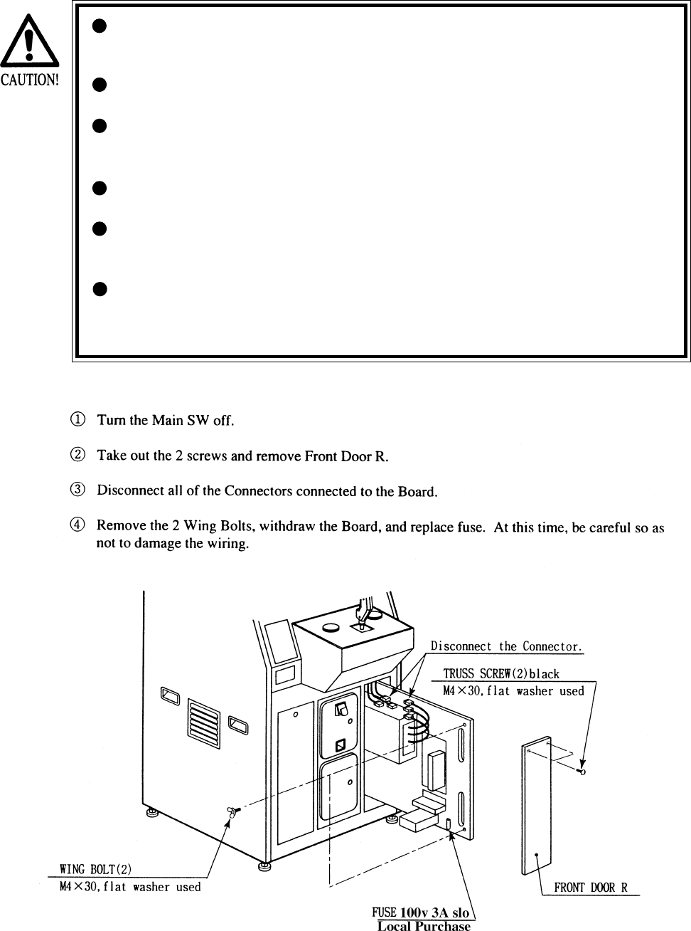
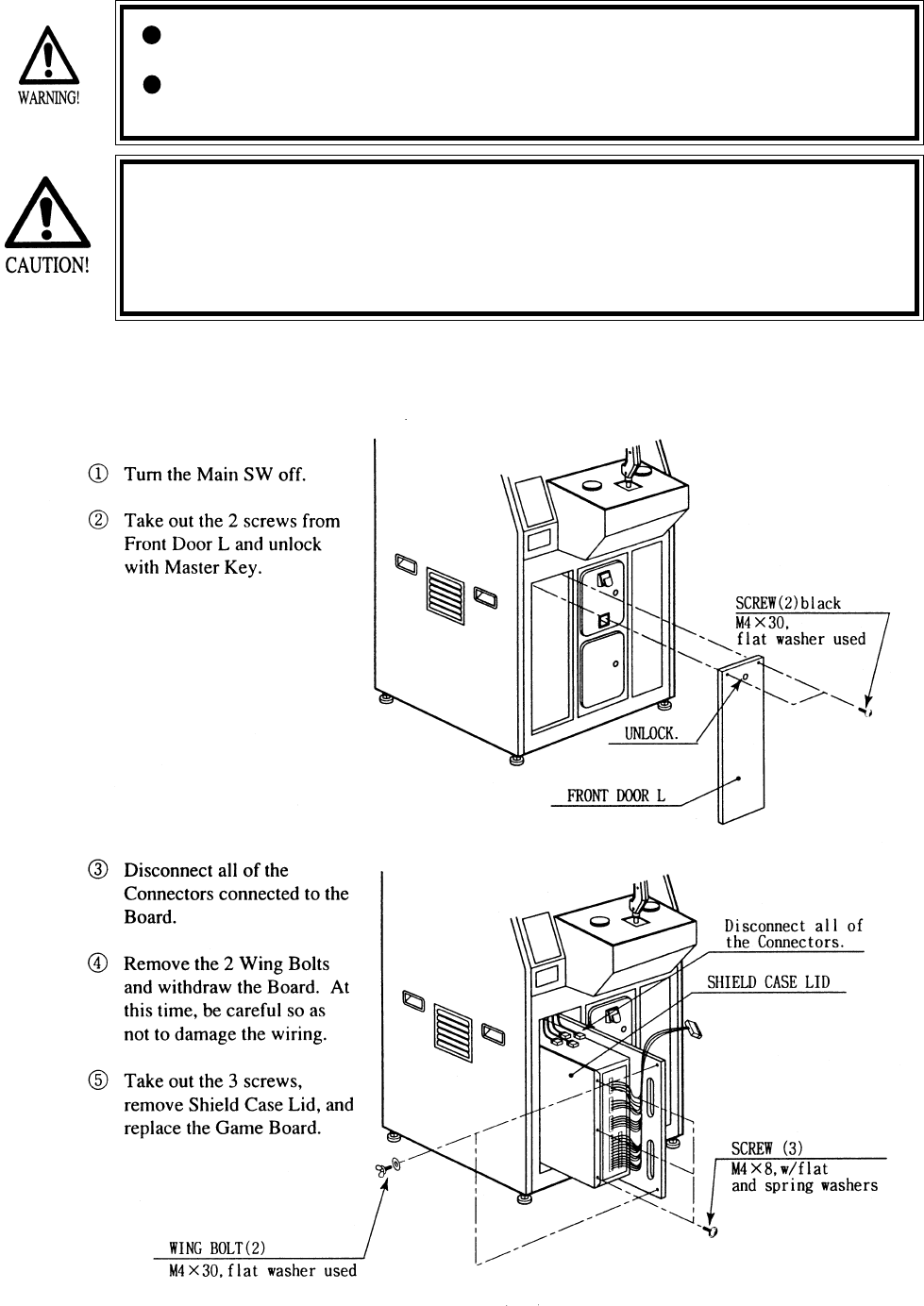
When replacing or inspecting the Game BD, take out the Game BD by using the following
procedure:
48
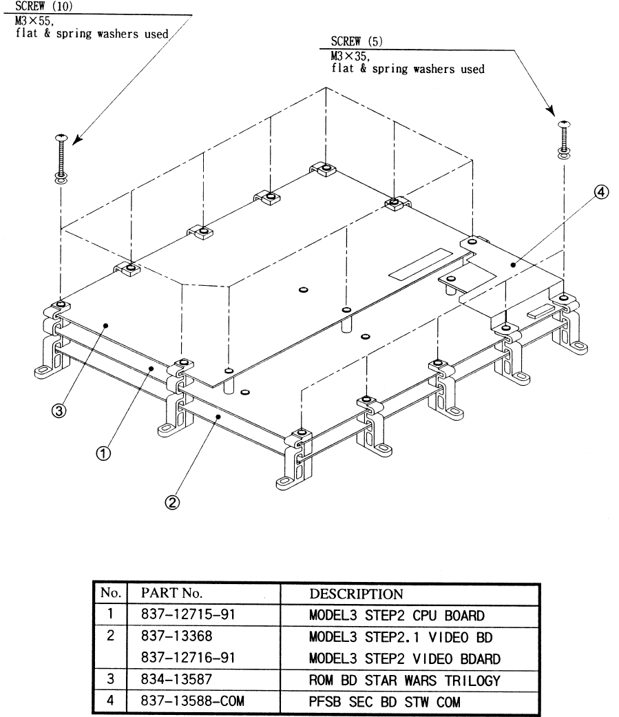
13 - 2 COMPOSITION OF GAME BOARD
GAME BDSTAR WARS TRILOGY (833-13586)
49
14. DESIGN RELATED PARTS
ITEM NO. PART NO. DESCRIPTION
1 STW-1509 STICKER SIDE L
2 STW-1510 STICKER SIDE R
3 STW-2501-B STICKER CONTROL PNL SIDE L
4 STW-2501-C STICKER CONTROL PNL SIDE R
5 STW-2501-D STICKER CONTROL PNL TOP
6 STW-2502-B STICKER CONTROL PNL SIDE COVER
7 STW-2504 CONTROL PNL PLATE
8 STW-0001 INSTR PLATE
9 DYN-0011 DENOMI PLATE W/O ORIGINAL
10 422-0706-01 PLAY INSTR SH STW U/R
11 422-0714 SUB INSTR SH STW U/R
12 421-7308~ DENOMINATION SHEET 1 GAME
13 423-0323 BILLBOARD PLATE STW U/R
50
15. PARTS LIST
TOP ASSY STAR WARS U/R
51
TOP ASSY STAR WARS U/R
ITEM NO. PART NO. DESCRIPTION
1 STW-10001 ASSY CABINET U/R
2 422-0706-01 PLAY INSTR SH STW U/R
3 422-0714 SUB INSTR SH STW U/R
4 STW-0001 INSTR PLATE
5 421-7308~ DENOMINATION SHEET 1 GAME
6 DYN-0011 DEMONI PLATE W/O ORIGINAL
16 421-9486-01 INSTR SH ACCESSORY ENG
201 008-T00412-0B TMP PRF SCR TH BLK M4X12
202 000-T00416-0B M SCR TH BLK M4X16
52
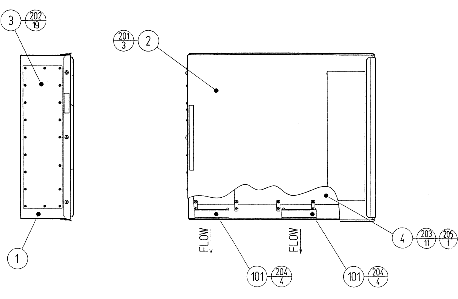
ITEM NO. PART NO. DESCRIPTION
1 105-5245X SHIELD CASE MODEL3 NVS
2 105-5242X SHIELD CASE LID MODEL3
3 839-0951 FILTER BD MODEL3 JPT
4 833-13586 GAME BD STW TRILOGY
101 260-0064 FAN MOTOR DC12V
201 000-P00408-W M SCR PH W/FS M4X8
202 010-P00308-F S-TITE SCR PH W/F M3X8
203 010-P00310-F S-TITE SCR PH W/F M3X10
204 000-P00320-W M SCR PH W/FS M3X20
205 010-P00365-F S-TITE SCR PH W/F M3X65
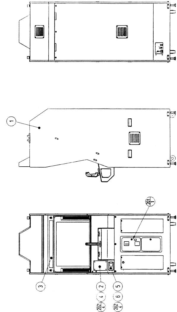
ASSY SHIELD CASE MAIN (STW-0100)
53
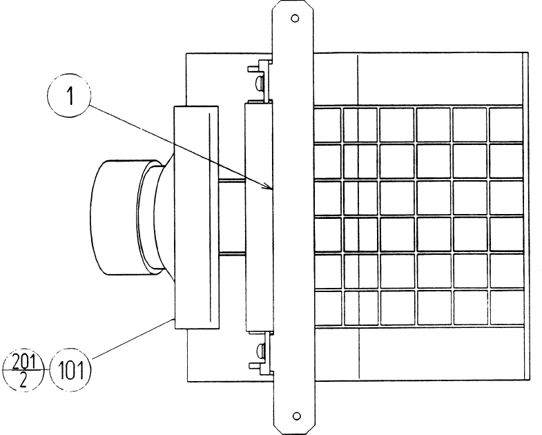
ITEM NO. PART NO. DESCRIPTION
1 HLD-1109 SP BRKT
101 130-5152 SPKR BOX MINI DOME 12W
201 000-P00412-W M SCR PH W/FS M4X12
ASSY SPEAKER (OCN-1090)
54
ASSYSUB-CABI U/R (STW1-1500)
55
ITEM NO. PART NO. DESCRIPTION
1 NOT AVAILABLE WOODEN CABINET (STW-1501)
2 STW-1530 ASSY FRONT DOOR L
3 JPT-1530 FAN UNIT
4 STW-1102 NUT PLATE FOR CASTER CE
5 ARC-1006 LEG BRACKET
6 117-5191 PLATE
7 GBN-1074Y MONITOR SUPPORT
8 117-5235 PLATE 6-30
9 253-5239-01 AIR VENT BLACK
10 105-5239-03 AIR VENT
11 STW-1502 BACK DOOR
12 DP-1167 TNG LKG
13 105-5169 LOCK BRACKET W
14 105-5172 CHUTE PLATE DOUBLE
15 253-5396-02 CABINET HANDLE WHITE
16 838-11856CE-02 CONNECT BD W/FUSE 6.3A CE
18 STW-1511 FRONT DOOR R
19 STW-1508 SW REG BRKT
20 STW-1509 STICKER SIDE R
21 STW-1510 STICKER SDE L
23 STW-1512 KEY COVER
24 117-5098 TNG RETAINER PLATE
28 OCN-1090 ASSY SPEAKER
29 OCN-1520-01 METER UNTI TWIN
102 220-5482-91 ASSY C.C 2DR
103 220-5574 CAM LOCK W KEYS
104 220-5575 CAM LOCK MASTER W/O KEY
105 999-0169 CASTER 2 12"
106 999-0167 LEG ADJUSTER 1/2X13X3
107 400-5330-03 SW REGU FOR MODEL 3
109 LOCAL PURCHASE ASSY FL20W W/CONN HIGH T CE
201 000-P00416-W M SCR PH W/FS M4X16
202 000-T00420-0B M SCR TH BLK M4X20
203 000-T00420-0C M SCR TH CRM M4X20
204 011-T00312 TAP SCR TH 3X12
205 011-P00325 TAP SCR PH 3X25
206 030-000630-SC HEX BLT W/S CRM M6X30
207 031-000630-0C CRG BLT CRM B6X30
208 050-F00600 FLG NUT M6
209 068-441616-0B FLT WSHR BLK 4.4-16X1.6
211 000-T00430-OB M SCR TH BLK M4X30
213 031-000530-0B CRG BLT BLK M5X30
214 050-F00500 FLG NUT M5
215 011-F00316 TAP SCR FH 3X16
217 030-000830-S HEX BLT W/S M8X30
218 060-F00800 FLT WSHR M8
219 060-F00600 FLT WSHR M6
220 011-T03512 TAP SCR TH 3.5X12
221 068-441616 FLT WSHR 4.4-16X1.6
222 010-P00406-F S-TITE SCR PH W/F M4X6
223 030-000830-0B HEX BLT BLK M8X30
224 060-F00800-0B FLT WSHR BLK M8
225 000-P00408-W M SCR PH W/FS M4X8
226 050-H01600 HEX NUT M16
227 000-P00420-W M SCR PH W/FS M4X20
ASSYSUB-CABI U/R (STW1-1500)
56
ITEM NO. PART NO. DESCRIPTION
1 STW5-1091 SW BRKT
101 220-5643-01 MAG CNTR DCV 6P WHMz-674-D04
METER UNIT (STW5-1520)
57
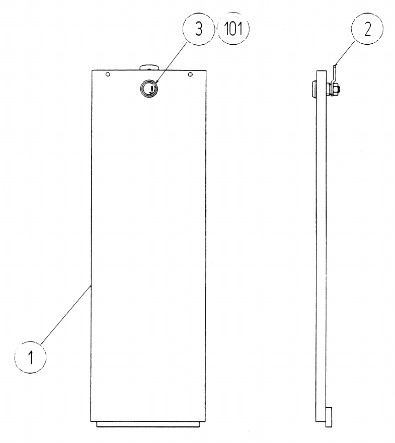
ITEM NO. PART NO. DESCRIPTION
1 STW-1531 FRONT DOOR L
2 DP-1148X LKG TNG
3 117-0062 PLAYTE LOCK RETAINER
101 220-5575 CAM LOCK MASTER W/O KEY
ASSY FRONT DOOR L (STW-1530)
58
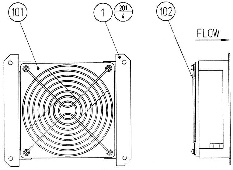
ITEM NO. PART NO. DESCRIPTION
1 105-5238 FAN BRKT
101 260-0011-02 AXIAL FLOW FAN AC100V 50-60Hz
102 601-8543 FAN GUARD
201 000-P00312-W M SCR PH W/FS M3X12
FAN UNIT (JPT-1530)
59
ITEM NO. PART NO. DESCRIPTION
1 STW-1541 WOOFER BRKT
101 130-5155 SPEAKER BOX SUB WOOFER
201 012-P00412 TAP SCR #2 PH 4X12
ASSY WOOFER (STW-1540)
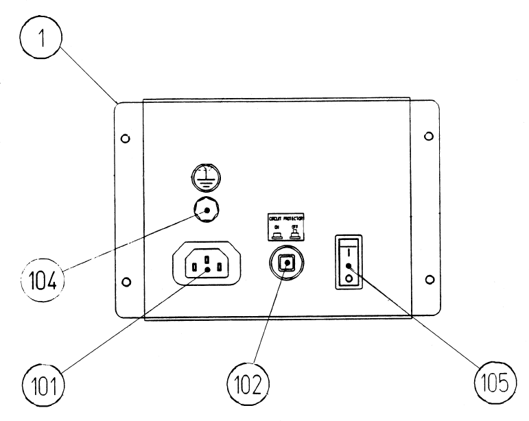
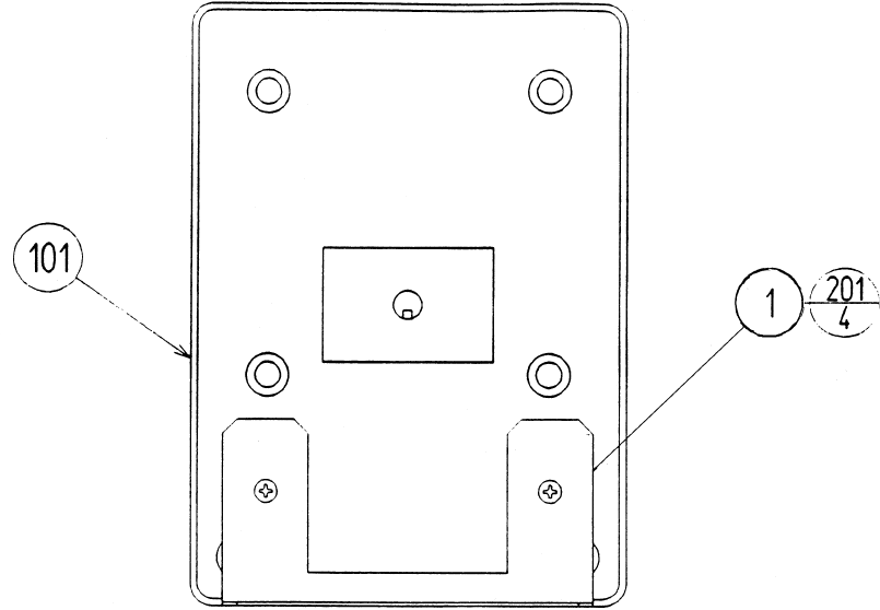
60
ITEM NO. PART NO. DESCRIPTION
1 STW-1561 AC BRACKET U/R
101 214-0202 AC INLET PANEL TYPE
102 LOCAL PURCHASE 5 A SLO FUSE
104 280-0417 TERMINAL BINDING POST BLACK
105 509-5453-91-V-B SW ROCKER J8 V-B
201 000-F00410 M SCR FH M4X10
202 010-P00306-F S-TITE SCR PH W/F M3X6
AC UNIT (STW1-1550)
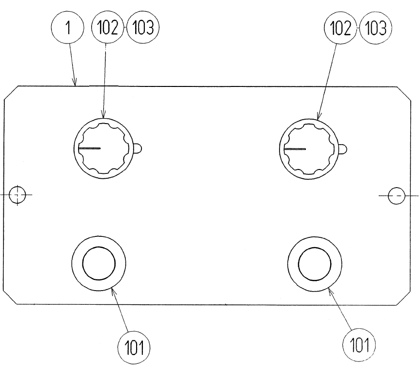
61
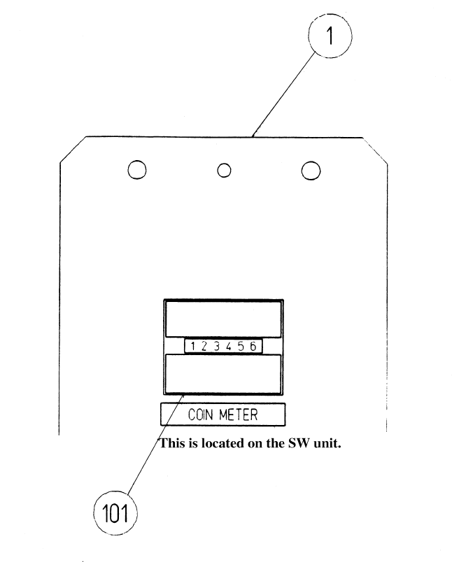
ITEM NO. PART NO. DESCRIPTION
1 STW5-1091 SW PLATE
101 509-5028 SW PB 1M (MIYAMA DS-412R)
102 220-5179 VOL CONT B-5K OHM
103 601-0042 KNOB 23MM
SW UNIT (STW5-1560)
62
ITEM NO. PART NO. DESCRIPTION
1 STW-2501 CONTROL PANEL BASE
2 STW-2502 CONT PNL SIDE COVER
3 STW-2503 RING PLATE
4 STW-2504 CONT PNL PLATE
5 610-0379 JOYSTICK W/TRIGGER HANDLE
101 509-5886-RE SW PB 60M RED W/H&L 14V2.7W
201 000-P00510-W M SCR PH W/FS M5X10
202 008-T00410-OB TMP PRF SCR TH BLK M4X10
203 000-T00408-0B M SCR TH BLK M4X8
204 068-441616-OB FLT WSHR BLK 4.4-16X1.6
ASSY CONTROL PANEL (STW-2500)
63
ITEM NO. PART NO. DESCRIPTION
1 105-5315 SHIELD CASE MPEG
2 105-5316 SHIELD CASE LID MPEG
3 105-5317 SHIELD CASE BRKT MEPG
4 837-13602 DIGITAL SOUND BD 2 STW
5 839-1021 FLT BD DIGITAL SOUND
201 000-P00408-W M SCR PH W/FS M4X8
202 010-P00308-F S-TITE SCR PH W/F M3X8
203 010-P00310-F S-TITE SCR PH W/F M3X10
ASSY SHIELD CASE DS2 (STW-4350)
64
ASSY PWR SPLY U/R (STW1-4500)
65
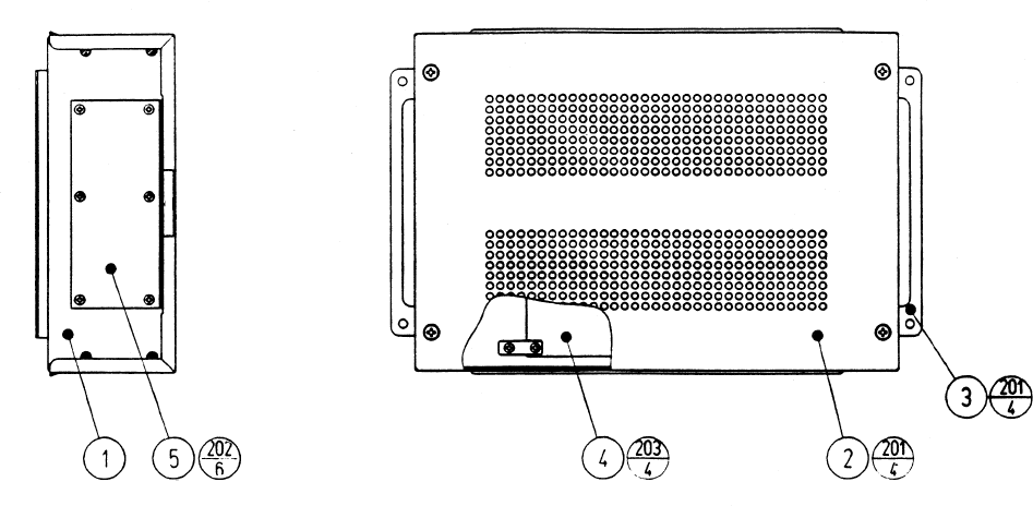
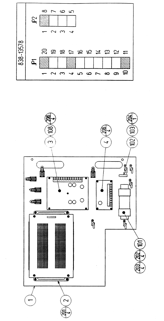
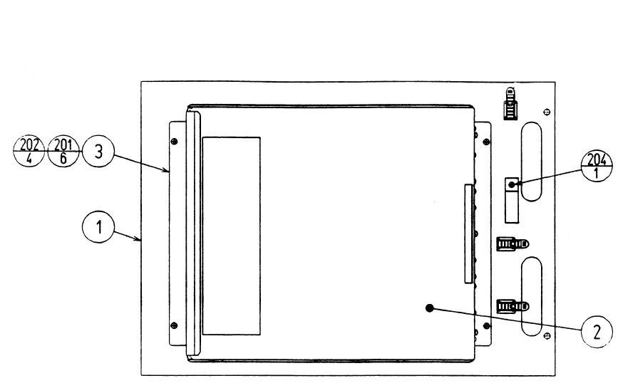
ITEM NO. PART NO. DESCRIPTION
1 STW-4501 WOODEN BASE PWR SUPPLY U/R
2 STW-4350 ASSY SHIELD CASE DS2
3 838-13578 PWR AMP 2CH & MIXER
4 838-11651-01 LOWPASS AMP W/LARGE HEAT SINK
101 560-5405-V XMFR 100V 14V 6.3A
102 LOCAL PURCHASE FUSE 6.25 A SLO
103 514-5084 FUSE HOLDER
108 211-5305 C JMPR SCKT (IMSA-9206H-GF)
201 000-P00412-W M SCR PH W/FS M4X12
202 000-P00416-S M SCR PH W/S M4X16
203 068-441616 FLT WSHR 4.4-16X1.6
204 011-F00310 TAP SCR FH 3X10
205 011-T03512 TAP SCR TH 3.5X12
206 011-P00325 TAP SCR PH 3X25
ASSY PWR SPLY (STW1-4500)
66
ITEM NO. PART NO. DESCRIPTION
1 STW-4601 WOODEN BASE MAIN U/R
2 STW-0100 ASSY SHIELD CASE MAIN
3 105-5241 SHIELD CASE BRKT
201 000-P00408-W M SCR PH W/FS M4X8
202 000-P00412-W M SCR PH W/FS M4X12
203 011-F00310 TAP SCR FH 3X10
204 011-T03512 TAP SCR TH 3.5X12
ASSY MAIN BD U/R (STW-4600)
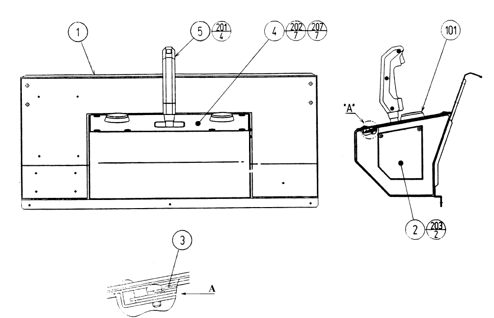
67
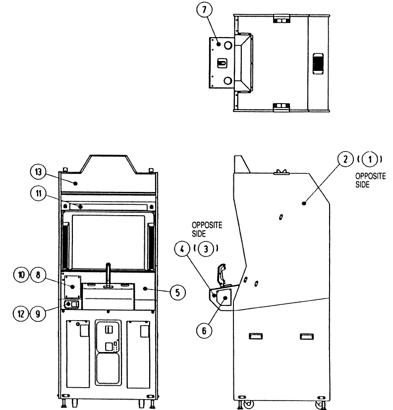
ASSY CABINET U/R (STW1-10001)
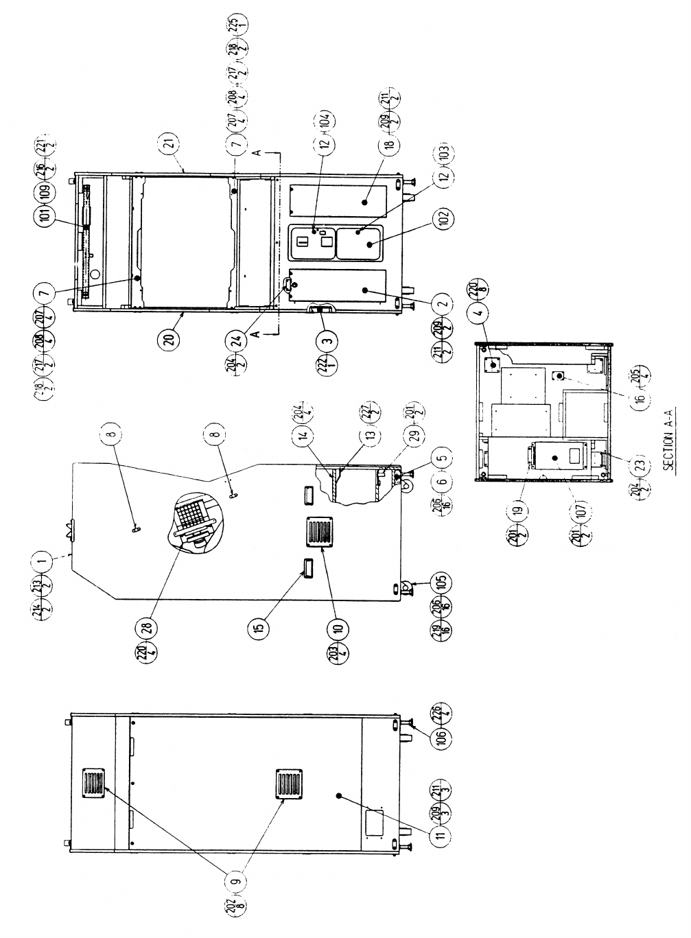
68
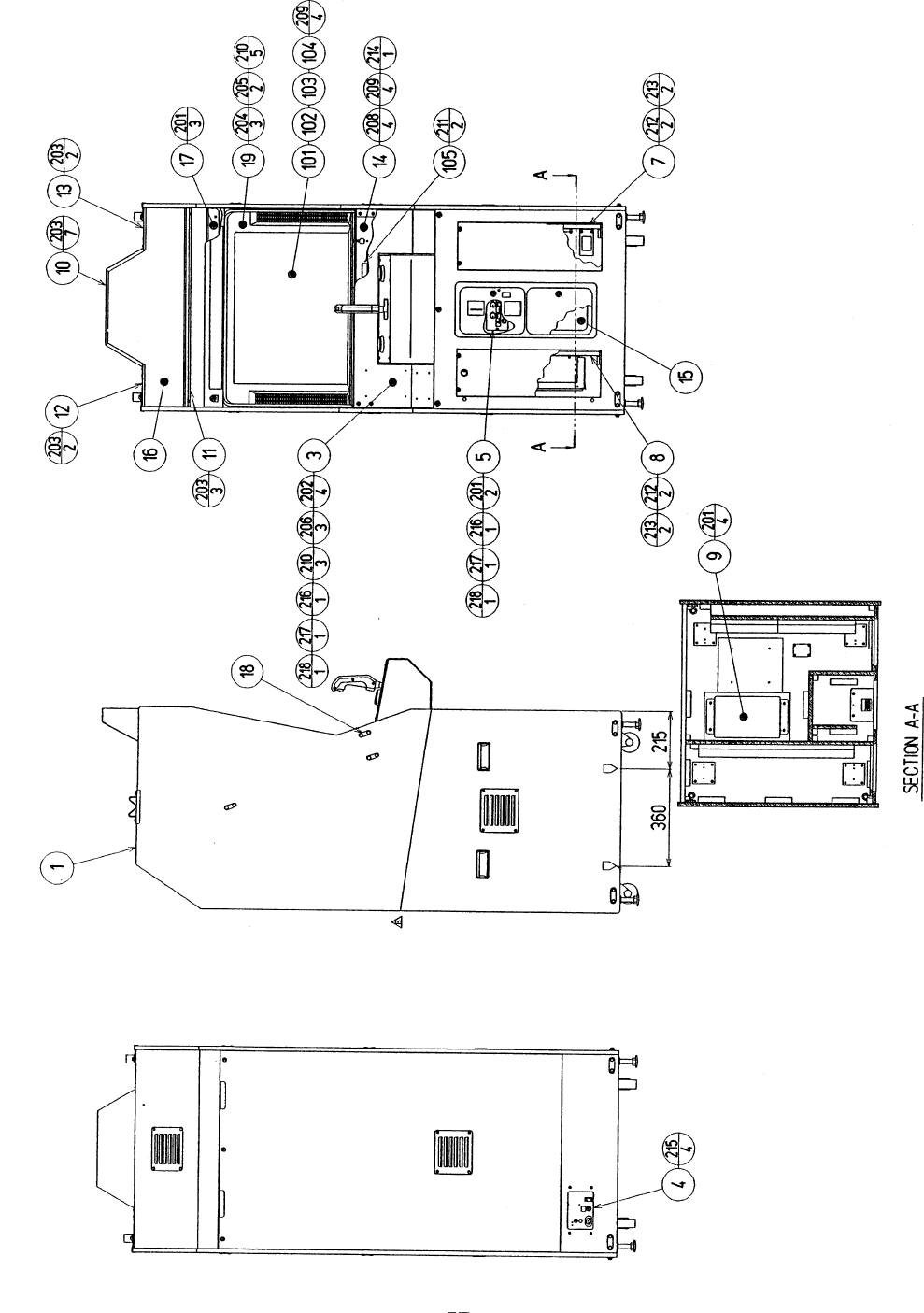
ITEM NO. PART NO. DESCRIPTION
1 STW-1500 ASSY SUB-CABI U/R
3 STW-2500 ASSY CONTROL PANEL U/R
4 STW-1550 AC UNIT U/R
5 STW-1560 SW UNIT
7 STW-4500 ASSY PWR SPLY U/R
8 STW-4600 ASSY MAIN BD U/R
9 STW-1540 ASSY WOOFER
10 STW-1503 BILLBOARD CASE
11 STW-1504 SASH LOWER
12 STW-1505 SASH UPPER L
13 STW-1506 SASH UPPER R
14 STW-1507 MASK HOLDER
15 BOX-CASH CASH BOX
16 423-0323 BILLBOARD PLATE STW U/R
17 GBN-1076 MASK SUPPORT
18 117-5235 PLATE 6-30
19 TTR-1067X MONITOR MASK
101 200-5242-24-04 ASSY CLR DSPL 29 TYPE 100 V
102 280-5112 BUSH FOR TV
103 280-5113 COLLAR FOR TV
104 280-5114 SPACER 6.4-25X2
105 280-5185-15 SPACER TUBE L=15
201 000-P00416-W M SCR PH W/FS M4X16
202 000-T00616-0B M SCR TH BLK M6X16
203 000-T00416-0B M SCR TH BLK M4X16
204 000-T00520-0B M SCR TH BLK M5X20
205 000-T00530-0B M SCR TH BLK M5X30
206 000-T00525-0B M SCR TH BLK M5X25
208 031-000630-0C CRG BLT CRM M6X30
209 050-F00600 FLG NUT M6
210 068-552016-0B FLT WSHR BLK 5.5-20X1.6
211 000-P00325-W M SCR PH W/FS M3X25
212 032-000430 WING BLT M4X30
213 068-552016-0B FLT WSHR BLK 5.5-20X1.6
214 000-P00408-W M SCR PH W/FS M4X8
215 000-T00420-0B M SCR TH BLK M4X20
216 050-H00400 HEX NUT M4
217 060-F00400 FLT WSHR M4
218 060-S00400 SPR WSHR M4
ASSY CABINET U/R (STW1-10001)
