Arcade Storm Racer G User Manual
2015-03-26
User Manual: Arcade Storm Racer G User Manual
Open the PDF directly: View PDF ![]() .
.
Page Count: 108 [warning: Documents this large are best viewed by clicking the View PDF Link!]
Ver.3.00
Please keep this manual properly for convenient reference as needed.
For safety reasons, please read the manual first before plugging in machine.
WARNING
OWNER
’
S MANUAL

About This Manual
Thank you for purchasing this product.
The manual describes how to install, set up, use and maintain the product.
The main purpose of the manual is to instruct how to operate the product
correctly and safely. Please follow all the safety and warning instructions in
the manual to avoid personal injury and product damage.
This product may only be maintained by a technician. A technician mainly
refers to a person who has obtained a certificate of senior middle school
related to mechanical engineering, electrical engineering or at a level equal
to that of technical senior middle school graduates, and is engaged routinely
in the maintenance, management, repair of amusement machine.
Please keep this manual properly for easy reference as needed. Moreover,
if the operator entrust another party to operate, move, transport, install,
maintain and repair the machine, please read relevant content and instruct
concerned party to observe all the instructions and precautions in this manual
regarding the particular action to be taken.
When transferring the ownership of this product, be sure to provide this
manual with the machine.
For further information about the game and repair (including consumables),
please contact our company.
© GuangZhou Wahlap Technology Limited All Rights Reserved.
© GuangZhou Wahlap Technology Limited All Rights Reserved.
Unauthorized reproduction of this document or any of its contents in
any form is strictly forbidden.

3. Game Description ...............................................14
4. Test and Setting .................................................16
3.1 Appearance Design.......................................................14
3.3 How to Play.............................................................14
3.4 Multiplayer Description ...................................................15
3.2 Game Introduction .......................................................14
4.3.1 Arcade Operation Mode ..............................................35
4.2.1 Front-End MENU ...................................................20
4.2.2 In-Game MENU ....................................................26
4.2.3 Back-End MENU ....................................................32
4.1.1 GAME FEATURE ...................................................16
4.1.2 GAME CONTENT ...................................................17
4.3.2 Languages ........................................................36
4.3.3 Master Volume .....................................................36
4.3.4 Idle Volume ........................................................37
4.3.5 First Round Coins ..................................................37
4.3.6 Second Round Coins ................................................38
4.3.7 Winner Bonus ......................................................38
4.3.8 Auto Pedal.... .....................................................39
4.3.9 Game Time .... ....................................................39
4.3.10 Clock........ .....................................................40
4.1 Game Description ........................................................16
4.3 Operator MENU .........................................................35
4.2 Game FLOW ...........................................................20
2.5 Packing List.............................................................11
2.6 Install Direction .........................................................12
2.7 Warranty ...............................................................13
Table of Contents
About This Manual
1. Safety Precautions ...............................................1
2. Product Description ..............................................6
1.1 Warning Stickers .........................................................1
2.1 Product Specification ......................................................6
2.2 Overview ...............................................................7
2.3 Spare Parts ..............................................................8
2.4 Shipment List ............................................................9
1.2 Placing Site .............................................................1
1.3 Safety Precautions ........................................................2
1.4 Precaution during Play .....................................................3
1.5 Transporting and Moving ..................................................3
1.6 Installing and Placing .....................................................4
1.7 Caution & Warning Stickers ................................................5

4.3.11 Income ..........................................................41
4.3.12 Record ..........................................................41
4.3.13 Sound Testing ....................................................42
4.3.14 Light Testing .....................................................42
4.3.15 Button Testing ....................................................43
4.3.16 Calibration Steering (Auto)...........................................44
4.3.17 Calibration Foot Pedal and Boost (Manual) .............................45
4.3.18 Video Split Number.................................................46
4.3.19 Video ID .......................... . . . ...........................46
4.3.20 Patch... .........................................................47
4.3.21 IO ... ..... . .....................................................47
4.3.22 Reset... .........................................................48
4.3.23 Save ... .........................................................48
4.3.24 Game-Play Screen Information .......................................49
5. Maintenance and Service .........................................50
5.1 Maintenance and Service .................................................50
5.2 Part Replacement .......................................................51
5.2.1 Replacement of acrylic signboard .....................................51
6.2.1 Main wooden frame assembly .........................................58
6.2.2 Main frame assembly ................................................60
6.2.3 Motor assembly ....................................................61
6.2.4 Power box assembly .................................................62
6.2.5 Transformer board assembl ...........................................63
6.2.6 Service board assembly .............................................64
6.2.7 Speaker assembly ..................................................65
6.2.8 Right small light assembly ............................................66
6.2.9 Left small light assembly .............................................67
6.2.10 Plastic step box assembly ...........................................68
6.2.11 PCB board assembl ................................................69
6.3.1 Seat wooden crate assembly .........................................71
6.3.2 Upper assembly of seat ..............................................72
6.3.3 Mainframe assembly ................................................73
5.2.2 Replacement of fluorescent plate.......................................51
5.2.3 Replacement of top light box ..........................................52
5.2.4 Key replacement ....................................................53
5.2.5 Replacement of pick-up head .........................................53
5.2.6 Replacement of coin acceptor .........................................54
6. Assembly .......................................................55
6.1 Assembly tree diagram ...................................................55
6.3 Seat assembly ...........................................................70
6.2 General assembly .......................................................56

6.3.4 Backrest horn assembly ..............................................74
6.4.1 Console keyboard assembly ..........................................76
7. Printing Pattern ..................................................96
8. Wiring Diagram ..................................................99
9. After-Sales Service..............................................102
6.10 Left side light assembly ..................................................82
6.11 Push rod assembly .....................................................83
6.12 Coin door assembly .....................................................90
6.13 Stepping cover assembly ................................................91
6.14 Pedal assembly ........................................................92
6.15 Upper assembly of back door plate ........................................93
6.16 Intermediate assembly of back door plate ...................................94
6.17 Steeling wheel assembly .................................................95
6.4 Plastic console assembly ..................................................75
6.5 LCD assembly ...........................................................77
6.6 LCD glass assembly ......................................................78
6.7 Pick-up head assembly ....................................................79
6.8 Billboard Assembly ......................................................80
6.11.1 Handle assembly ..................................................84
6.11.2 Left side plate assembly ............................................85
6.11.3 Right side plate assembly ...........................................86
6.11.4 Drive shaft assembly ...............................................87
6.11.5 Electromagnet assembly ...........................................88
6.11.6 Suction block assembly ............................................89
6.9 Right side light assembly .................................................81
1.1 Warning Stickers
1.2 Placing Site
In order to avoid injury to related people and damage to property, please
observe the followings:
PLEASE READ FIRST
PLEASE READ FIRST
The following marks can be used to indicate the magnitudes of risk and
damage caused by ignorance or improper operation:
Warning
Warning
Warning
Warning
Caution
Caution
means “may result in serious injury or death”
means “may result in minor injury or property
damage”
Serious Injury
Serious Injury
: refers to the situations in which hospital treatment or long-term treatment
will be accepted because of losing sight, getting hurt, getting burnt, electric
shock, fracture or intoxication.
Minor Injury
Minor Injury
: refers to the cases that there is no need to go to hospital or accept long-term
treatment.
Property Damage
Property Damage
: refers to the damage of house, facility, or hurt of livestock and pet
This machine is designed for indoor use only. Never install the machine
outdoors. Meanwhile, please avoid the following locations indoor:
please make sure the place line has been grounded before product
installation, setup, testing, operation or repair
The rear part has the vent for heat emission from PC or screen.
Don’t place anything nearby to avoid game failure.
Provide a space of minimum 30cm between the rear of the machine
and the wall for good ventilation and heat emission
1. Safety Precautions
Direct sunlight, water leakage, damp and high temperature places.
Near Flammable, volatile, or/and dangerous substance.
Slope, unstable places or locations subject to frequent vibration.
Near emergency exit, fire extinguisher or similar equipment.
Warning
Warning
1.3 Safety Precautions
The owner shall pay attention to the followings when placing, checking
and repairing machine to insure player’s security and avoid damage:
Make sure to plug the game into 110V or 220V main outlet to avoid fire
and electric shock.
please check the voltage is 110V or 220V before the machine connectes
to the power supply,or it may cause a fire or electric shock.
Do not unplug or plug the plug instantly.
Don’t touch the power plug with a wet hand to avoid electric shock.
Don’t expose the power cord/grounding line on the passageway.
Failure to do this will damage the power cord, causing electric shock
or short circuit.
Don’t lay anything near the power cord to avoid fire.
Do not pull the power cord when unplugging, please hold the plug to
avoid power cord damage, causing fire or electric shock.
Only use fuse and spare parts specified by our company
Connect the connector firmly and tighten the screws.
Do not dismount, replace or convert the product without our permission
in order to avoid damage and human injury due to improper operation.
Check and maintain the machine regularly.
Keep “Warning stickers” clean and legible. Replace it immediately
when the words are not legible or the dirt can’t be removed.
Please contact our service center when performing any work that is
not described in this manual, and follow the instruction provided.
Make sure to turn off the power when performing maintenance and
service to avoid electric shock or short circuit.
In case of power cord damage, please contact the local distributor for
replacement
Transporting
Transporting
When transporting the machine with an elevator, be sure to employ “Lift Point”
to prevent accident and damage to the machine.
To prevent movement when transporting the machine on a vehicle, please fix the
casters and fully retract the adjusters. Failure to do this may cause damage to the
machine.
When carrying the machine with a forklift, be sure to insert the fork to fork position
and lift stably. If not, it may cause accident and damage to the machine.
The glass and LCD screen are fragile. Avoid violent vibration or shock when
transporting.
Moving
Moving
Before moving the machine, unplug the power plug to prevent accident.
Don’t damage the cord.
Pay attention to the obstructions and uneven surface when moving the machine
to prevent accident and damage to the machine.
Fully retract all adjusters before moving to prevent accident and hazard.
Make sure to use at least two persons to conduct the above work to avoid accident
and injury
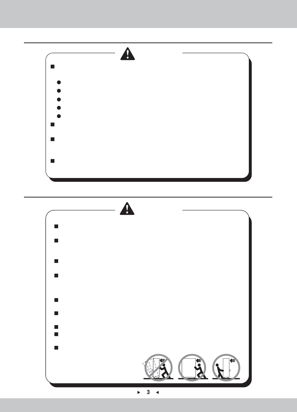
Pay attention to the moving direction, see fig.
1.4 Precautions during Play
Caution
Caution
Caution
Caution
Person with poor health condition, such as hypertension or heart disease.
When a player feels uncomfortable during play, remind the person to have
a break, or stop playing.
Make sure the player reads the warning labels and other indications, and
plays in accordance with the instructions to avoid accidents such as electric
shock and short circuit.
Bystander shall not operate any button when the player is playing the game
to avoid unnecessary trouble.
In order to avoid injury and accident during play, the following people shall
not play the game:
People who are injured or less mobile.
Person wearing high-heeled or slippery shoes.
Person who can’t touch the pedal.
Pregnant woman, drunk people.
1.5 Transporting and Moving
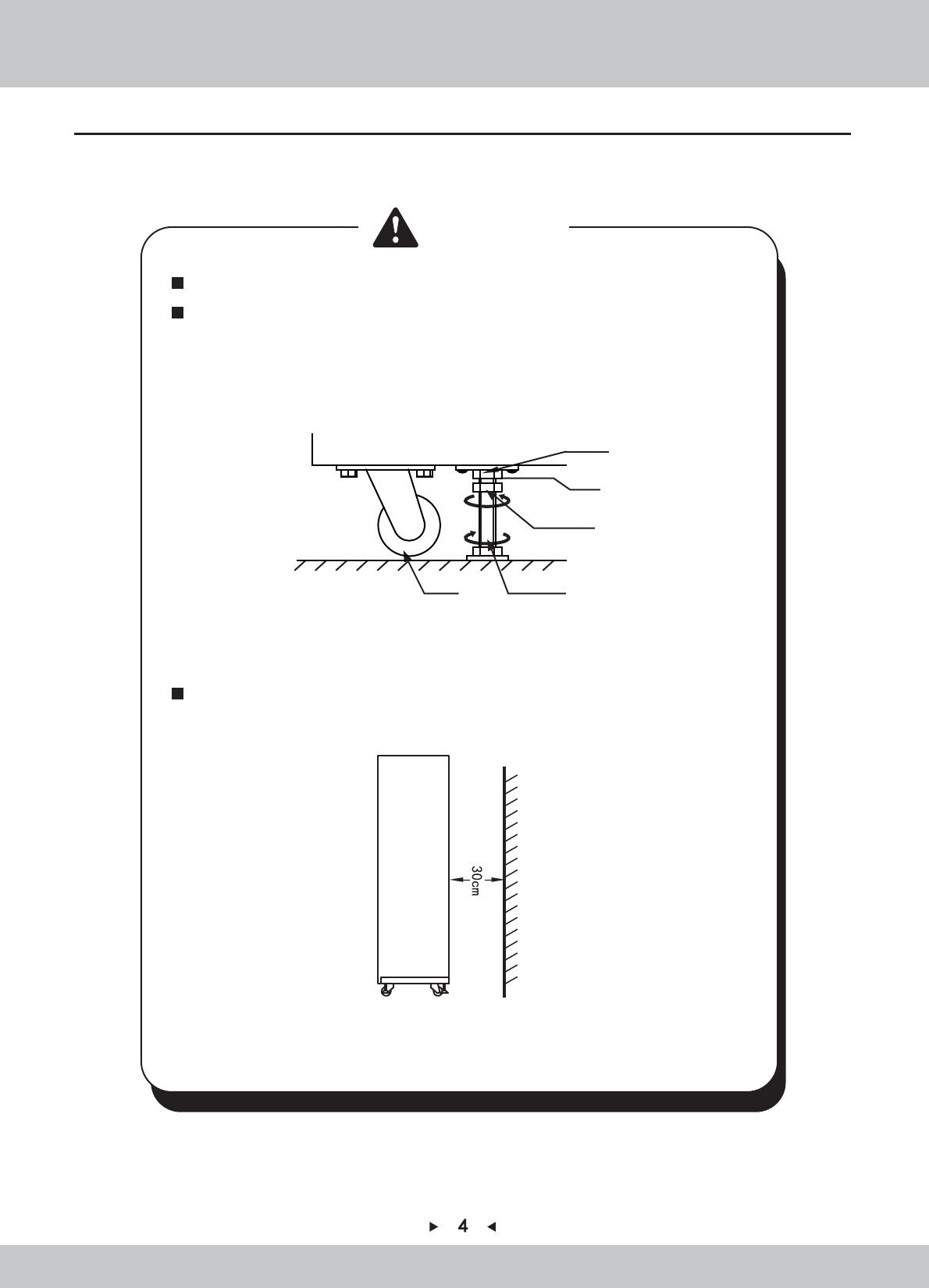
Use the adjusters to fix the machine (See diagram 1)
1.Loosen the nuts for the adjusters (clockwise), tighten the bolts with a wrench (clockwise).
2.Tighten the nut firmly(counter clockwise) and fix it well.
Diagram (1)
Diagram (2)
Provide a space of minimum 30cm between the rear of the machine and
the wall for good ventilation and heat emission (See diagram 2).
Wall
bracket
Lock nut
Lock place
Caster Adjuster Bolt
Caution
Caution
1.6 Installing and Placing
Pay attention to the following when placing the machine.
Place the machine on the flat and slip resistant area.
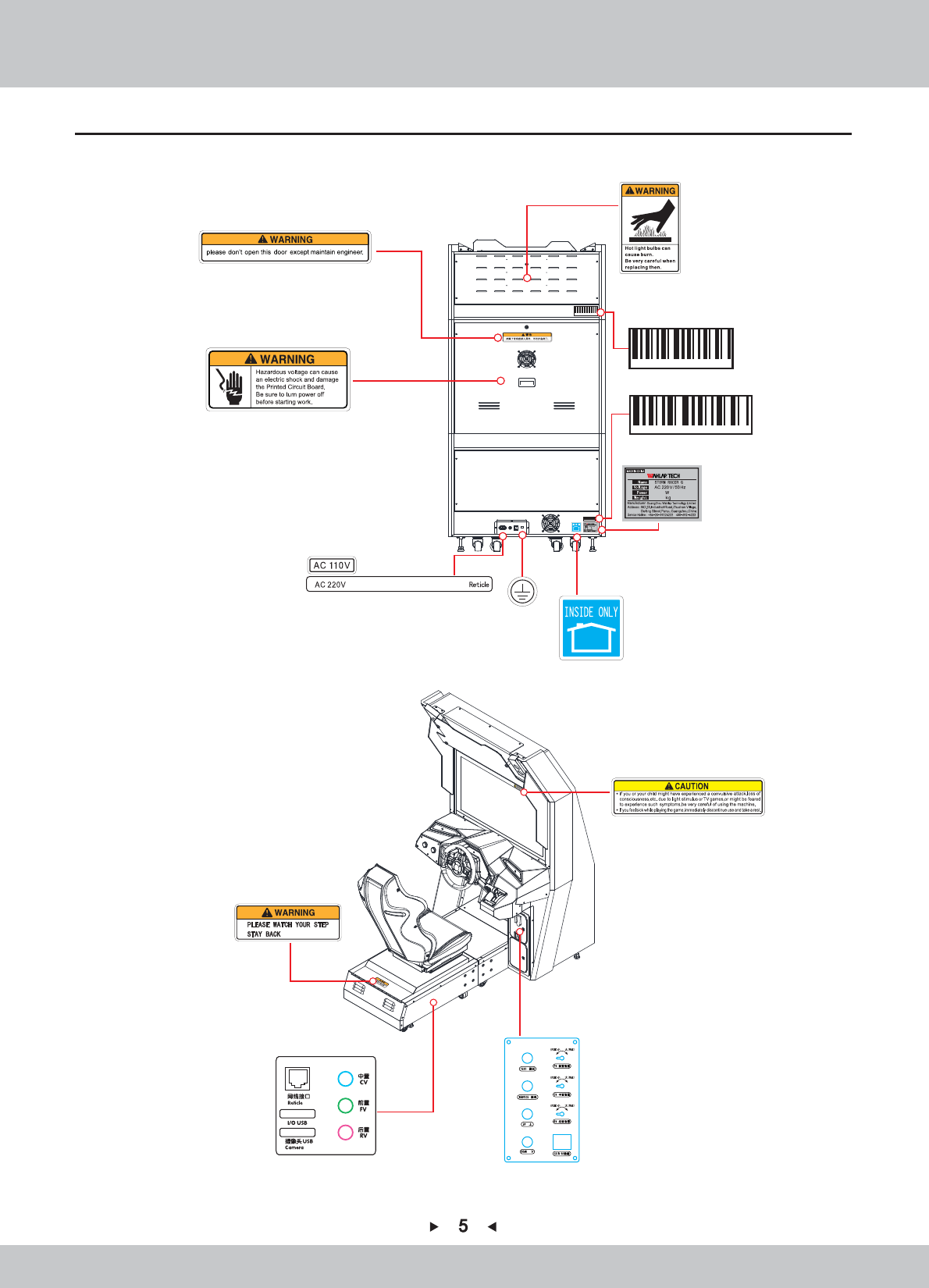
1.7 Caution & Warning Stickers
SRF-P0040
雷动G
680
270
Or
Inside
6A Power
680
270
6
6
2. Product Description
2.1 Product Specification
Indoor Only
220V
50Hz
680W
270kg
Location
Dimension
Rated Voltage
Frequency
Power Consumption
Weight
Temperature Range 5~40 。
C
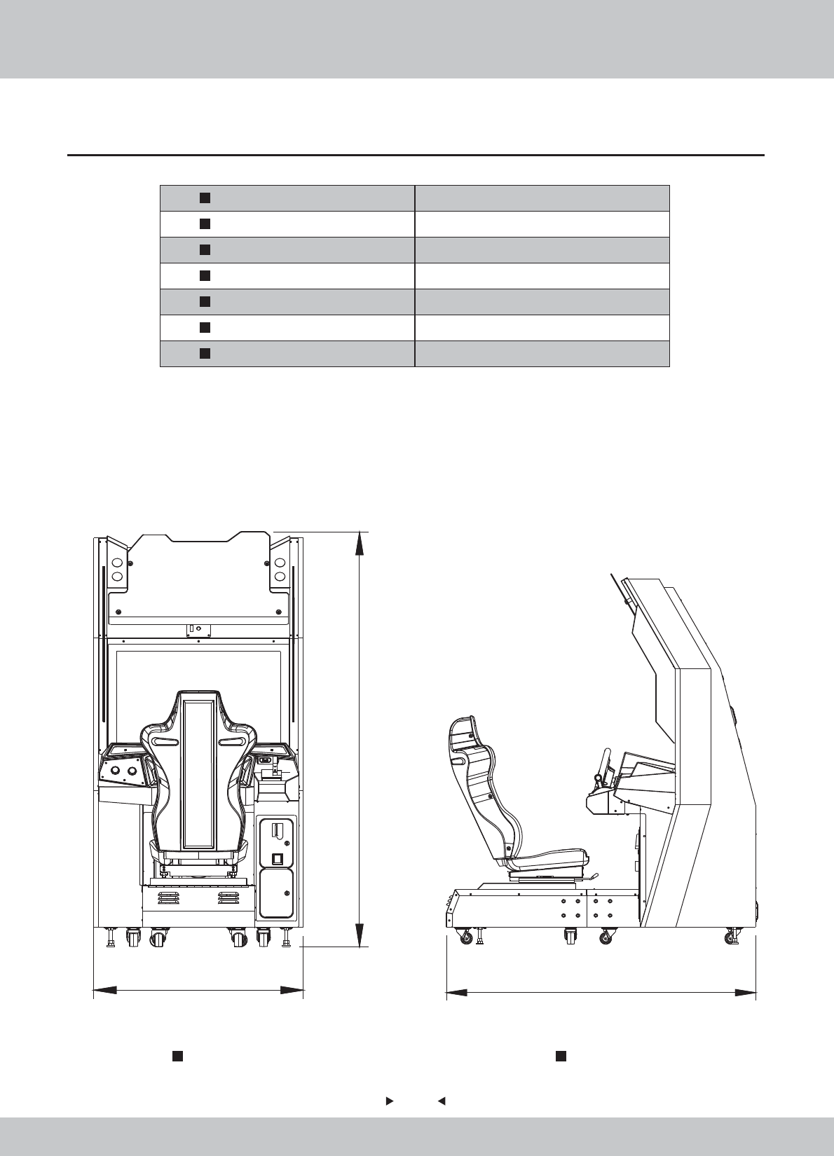
Front View Side View
1050mm
2075mm
1050(W)×1730D)×2075H)
1730mm
7
7
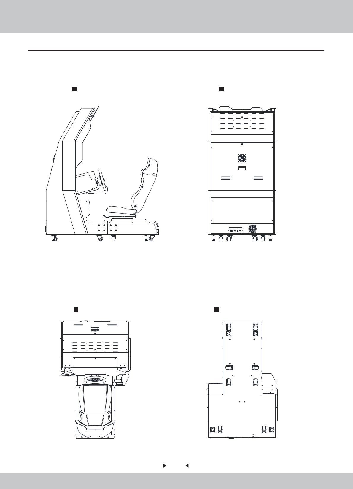
Rear View
Bottom View
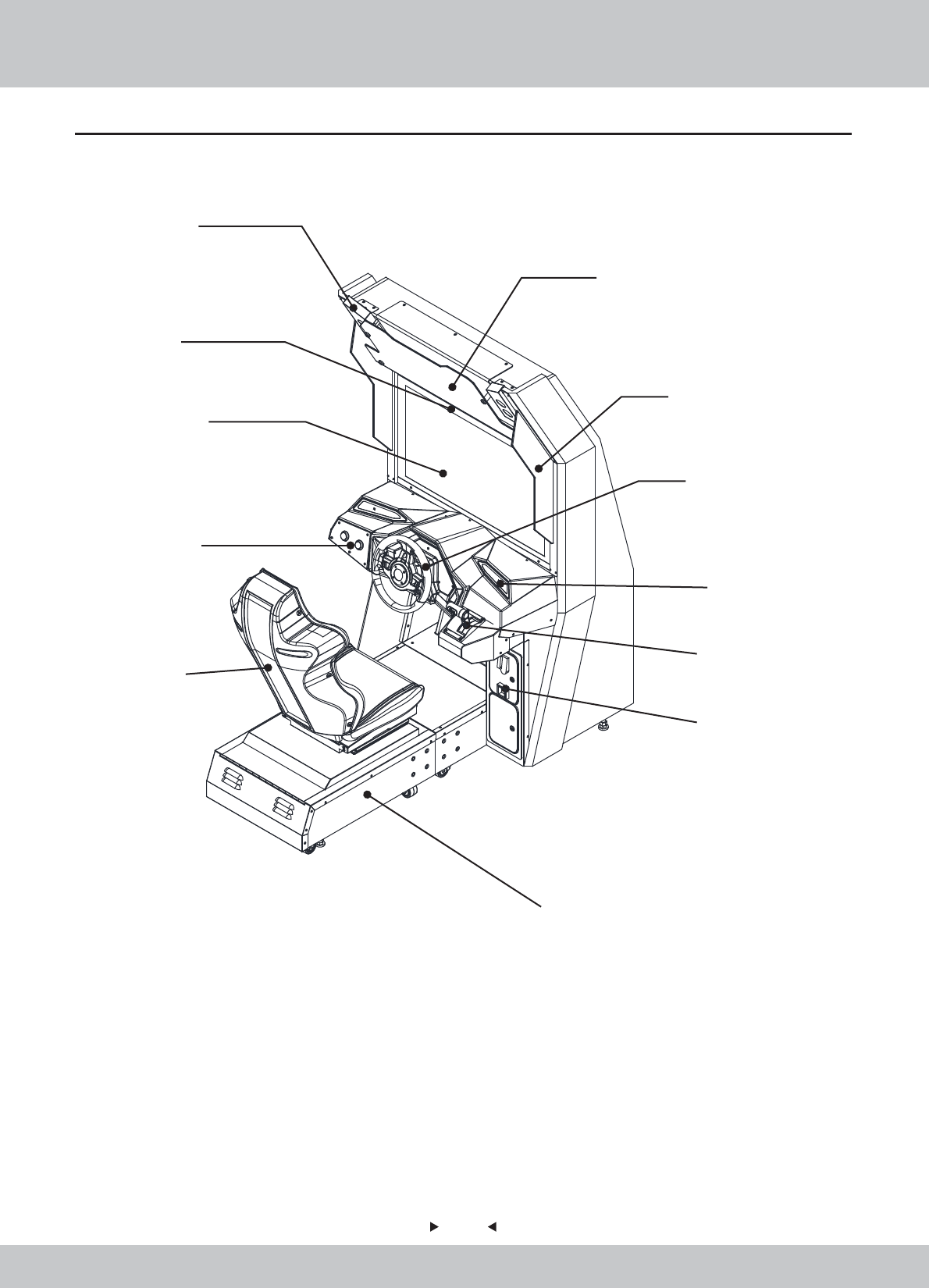
2.2 Overview
Side View
Top View
8
8
2.3 Spare Parts
Pick-up head
light box
Display
console
seat
Base
service door
handle
side decorative
acryl
steering wheel
top decorative acryl
speaker
9
9
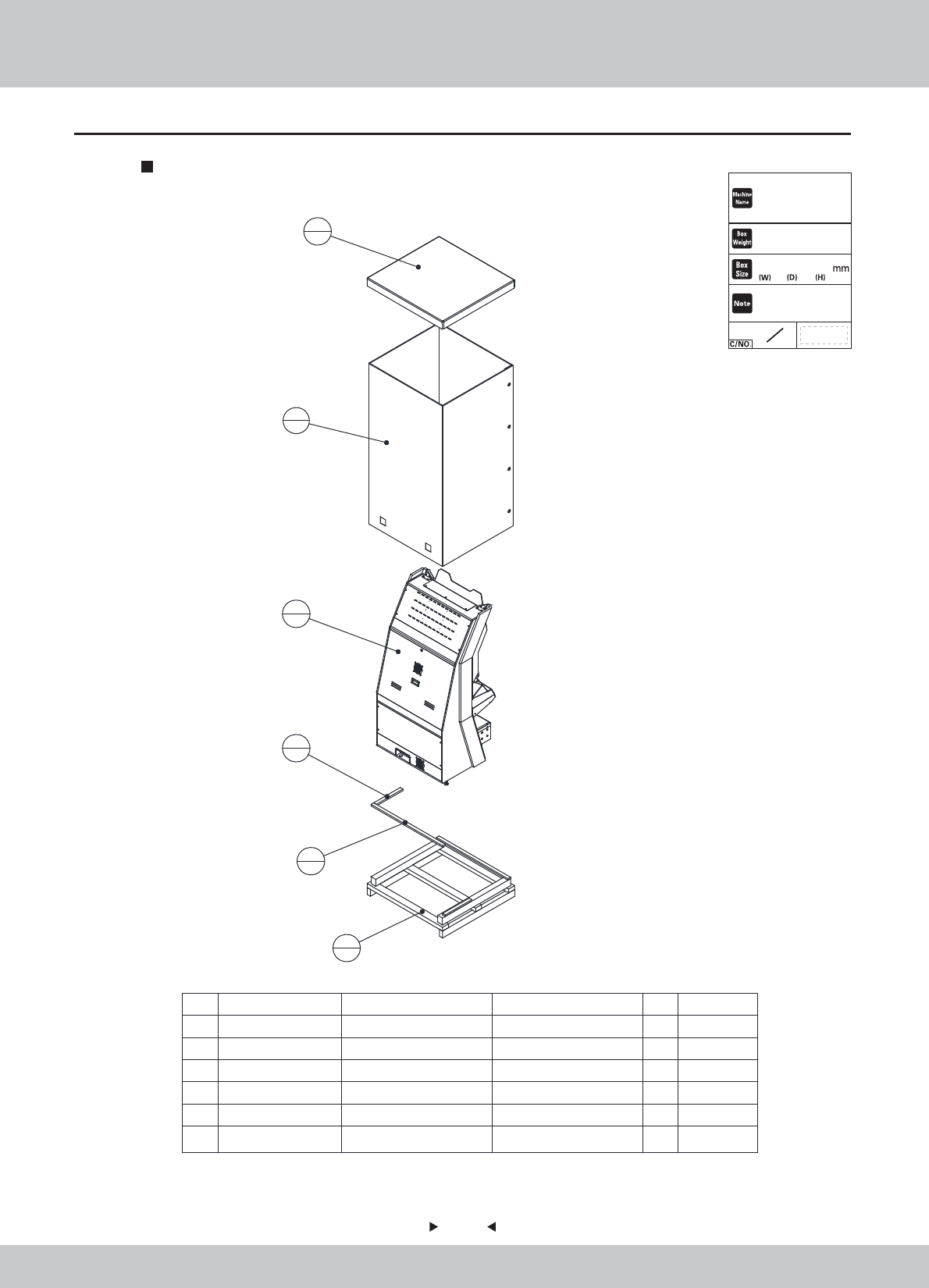
2.4 Shipment List
Packing Carton 1
6 SRF-9901E05 框体限位木条02 实木 20*40*1077 1
5 SRF-9901E04 框体限位木条01 实木 20*40*400 1
4 SRF-9901E03 框体天盖 耐水3C1100G T-10 1
3 SRF-9901E02 框体围框 耐水3C1100G T-10 1
2 SRF-9901E01 框体地台 1
1 SRF-0100000-A 主框体组件 1
序号 图 号 名 称 材料/规格 数量 备注
2
1
6
1
5
1
1
1
3
1
4
1
1147×1094×2240
Complete Unit
STORM RACER G
270 kg
2
1条形码粘贴处
10
10
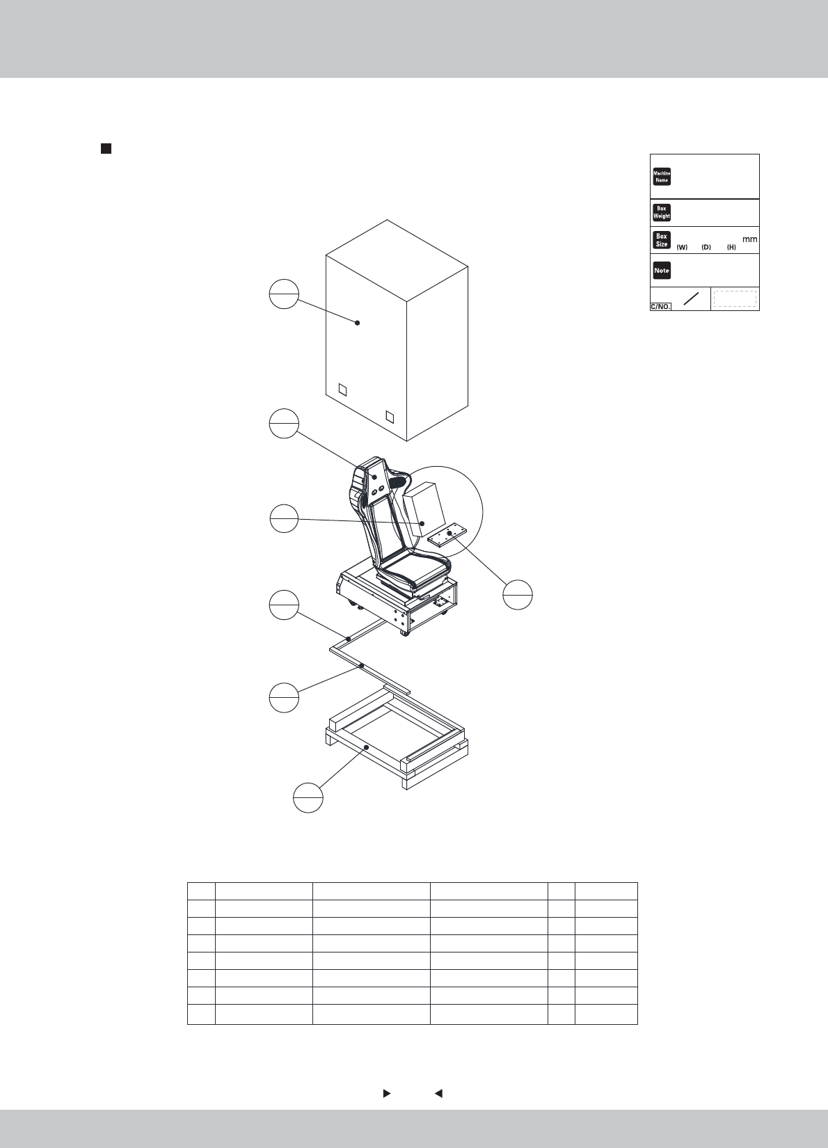
Packing Carton 2
7附属品箱 345*255*110mm 1
6 SRF-0000A01 框体连接铁 SPCC-1.5T 2
5 SRF-0200000
座位组件
1
4 SRF-9902E04 座位限位木条02 实木 20*40*865 1
3 SRF-9902E03 座位限位木条01 实木 20*40*565 1
2 SRF-9902E02
座位无底半页箱
耐水3C1100G T-10 1
1 SRF-9902E01
座位地台
1
序号 图 号 名 称 材料/规格 数量
备注
1
1
4
1
3
1
5
1
2
1
7
1
6
2
905×685×1490
85 kg
2
2
Chair、Accessary Carton
条形码粘贴处
STORM RACER G
11
11
1
16
16
16
1
1
2
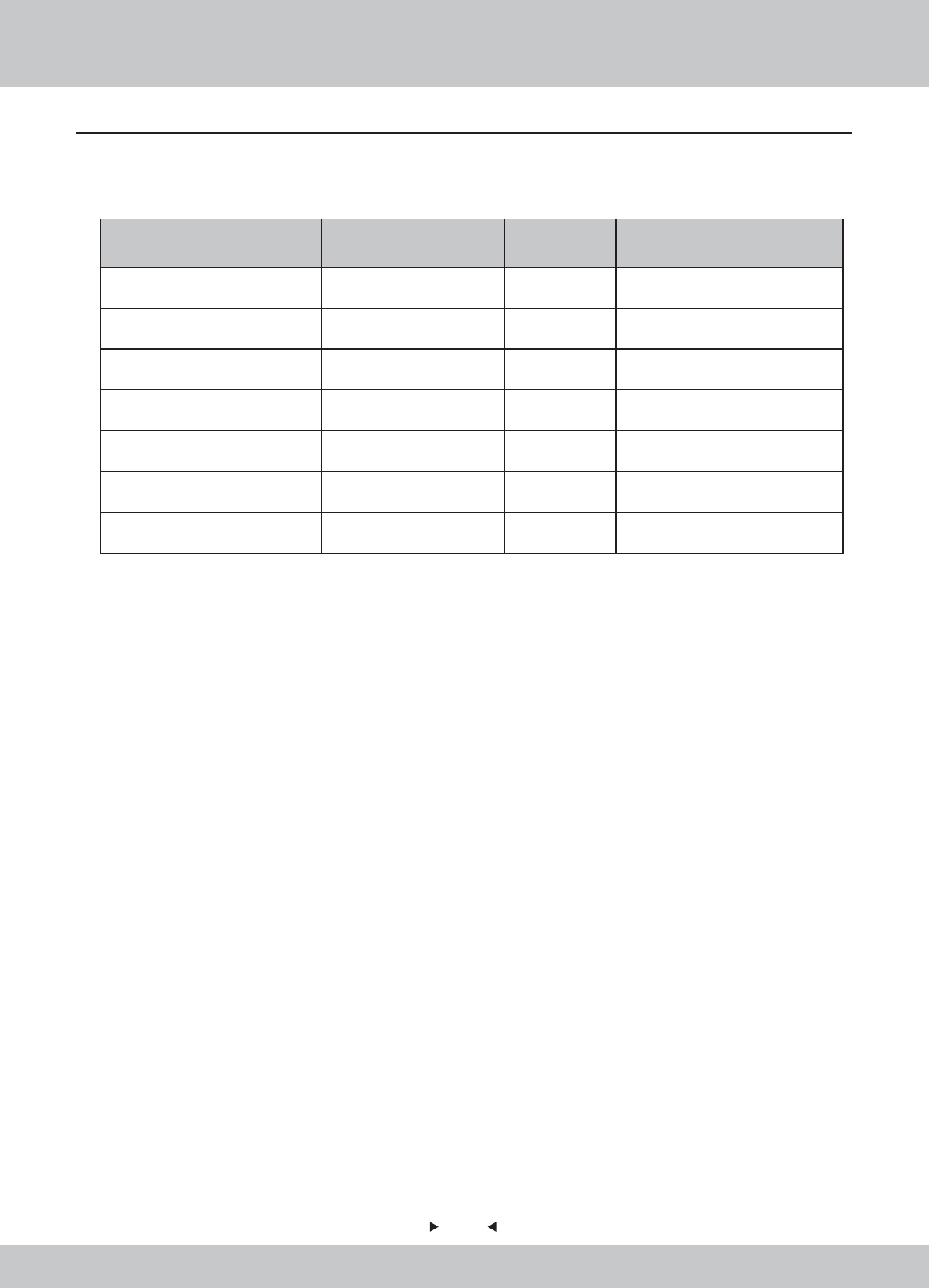
2.5 Packing List
Please check the following items after purchasing our product. If any part
missing or damaged, please contact our sales person!
Description Specification Quantity Remarks
Powerline
flatgasket
Spring gasket
outer hexagon
Reticle
3m(1.0m㎡) 250V
5555 keykey
Φ6*Φ20*2.0
M6
M6*40
AMP gigabit 10M
OWNER’S MANUAL
12
12
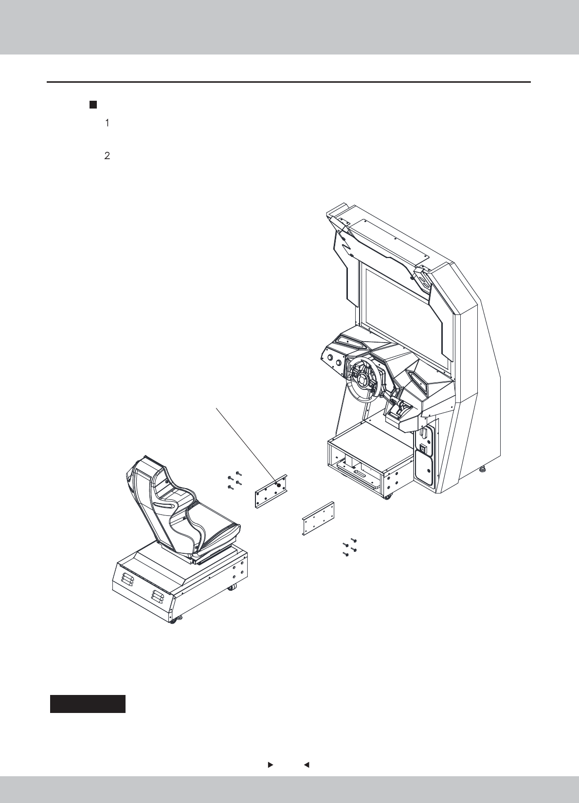
2.6 Install Direction
Steps
、 After opening the packing cartons 1 and 2, find the carton of accessories and outer
hexagon M6*40 with flat spring washer shown as following figure.
、Assemble the machine by using the method shown in following figure.
outer hexagon M6*40
Special attention:When special case occurs in shipment, please check “Installation guide” in attachment box of
shipment, and make assembly according to installation guide; special supplement will not be
made in this instruction.
Damage caused by force majeure such as god will.
Failure caused by carelessness, such as water contact, falling down,
toppling, knocking.
Failure caused by disobeying the instructions in this manual.
Failure caused by operating the machine on inappropriate site.
Change the original design and configuration for the game without notice.
Failure to perform regular service and clean.
Failure to fix the product in line with the manual’s requirement.
Malfunction or part damage caused by electromagnetic interference other
electronic equipments generated.
Non-warranty Consumables
Light tube and bulb
Button lamp and switch
Fragile items
Solenoid
Other spare parts
13
13
2.7 Warranty
Scope
Inquiry regarding product can be assisted for free.
The warranty scope for consumables and durables may differ from product
to product. Please contact our after-sales service center for detailed
information. The right of final interpretation is reserved.
Exclusive

14
14
3. Game Description
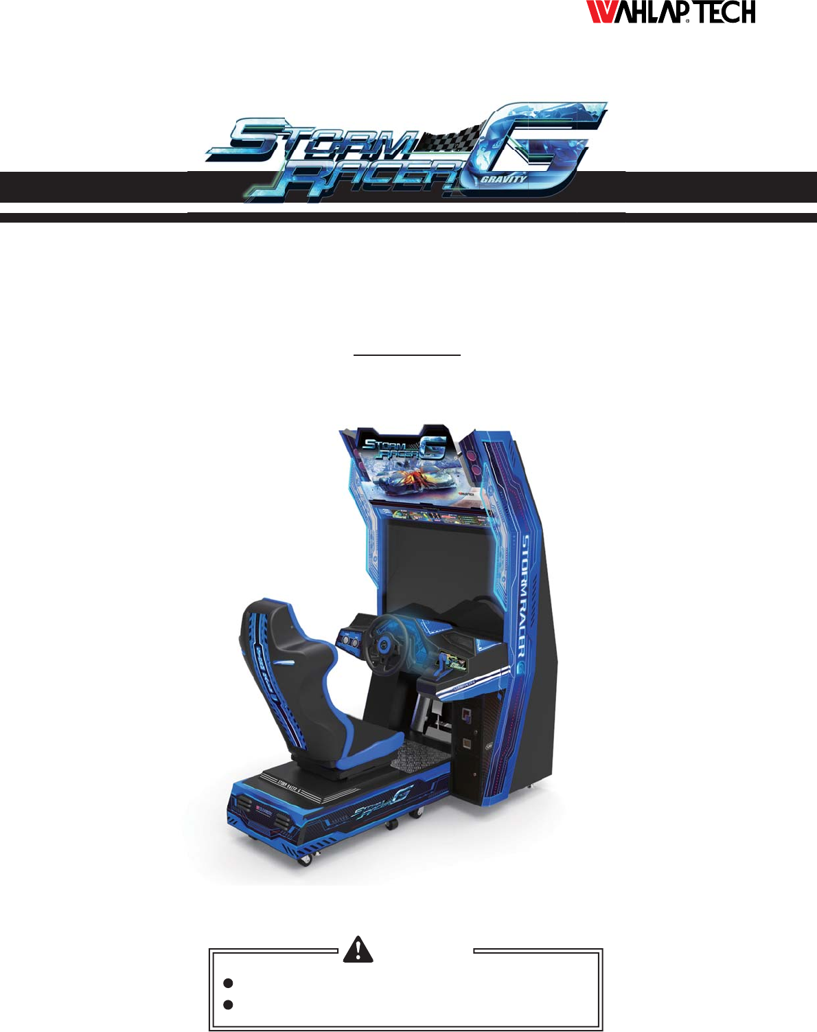
This machine has fashionable and beautiful appearance. The whole machine uses blue and
black color tone and acrylic decoration permeable to light is used on its sides to let the blue light
be visible when light is on, while the racing game is shown on the top decorative acryl, without
excessive decoration on the whole machine, so that the machine gives a stylish and elegant
feeling. With respect to the operation, continue the usual mode of operation in racing game so
that it is easier for the player to use and manipulate it.
3.2 Game introduction
Thunderous racing is a racing game, which uses 37inch LCD display, possesses 720DP HD screen
with 60 frames per second; the whole game has six characteristic scenes, 12 race tracks, four difficulty
levels of primary, intermediate, higher and extreme; support the multiplayer of at most 8 persons; in
game, the sports car has strong individuality, with highly sensitive control performance and new
thunderous acceleration system, so that different sports cars possess different operational advantages
on different race tracks.
3.3 How to play
1、Use the traditional mode of operation including steeling wheel+pedal, at the same time, add
the unique accelerator handle;
2、The game rules: after coin, press START (START) key or step on the gas to enter into the
screen of selecting the race track, turn the steeling wheel for left and right selection, after the
race track is determined, select the sports car by using the same method, after pressing START
key, the game has begun and the sports car is ready, by stepping on the gas, you can play the
game; the condition of accelerometer is shown on bottom right corner of screen, after certain
thunderous value is collected, push the manual gear lever forward to enable the acceleration
function of sports car.
3.1 Appearance Design
15
15
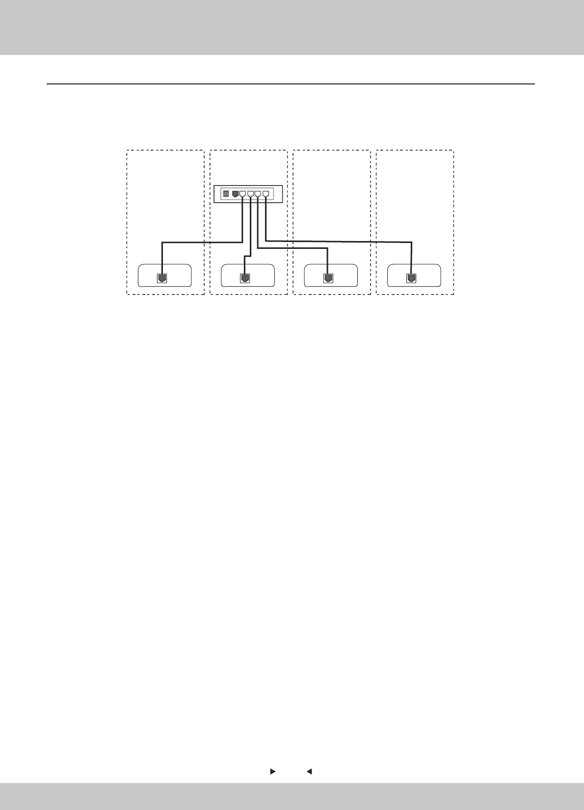
3.4 Multiplayer Description
if the multiplayer game is played in the store, please refer to the following figure (take the connection
of four machines as the example) and connect the network cables of mainframes of all machines to
the jacks of broadband router. For broadband router,
Remarks:
2. This wiring diagram is only for reference and the actual connection method is possibly different
due to network environment.
1. Please confirm the model of broadband .
1P 2P 3P
Wide Band Router
4P

16
16
4. Test and Setting
4.1 Game Description
• Up to 8 Players (LAN)
• HD 720p Resolution
• 30”inches screen
• 60 Frames per Second; High Sense of Speed with Fluent Game Play
• Online Patching /Upgrade Support
• Cloud-based Server
-Advantage: Stable Internet Speed for All Regions
• Classic Arcade Racing Style
• Auto/Manual Drift Mode for Beginner/Expert
• Competitive AI
• Full Force Feedback Steering Wheel
• Unique Throttle for Boost
• 4.1 Sound System
• Vibration Speakers under the Seat simulate Car Response
• Intense Game Play Embedded with Camera Kit
• Compatible Low Maintenance Cost PC with Sandy Bridge Standard
• Total of 12 Tracks with 6 Hidden Tracks; Total of 14 Cars with 7 Hidden Cars
4.1.1 GAME FEATURE
17
17
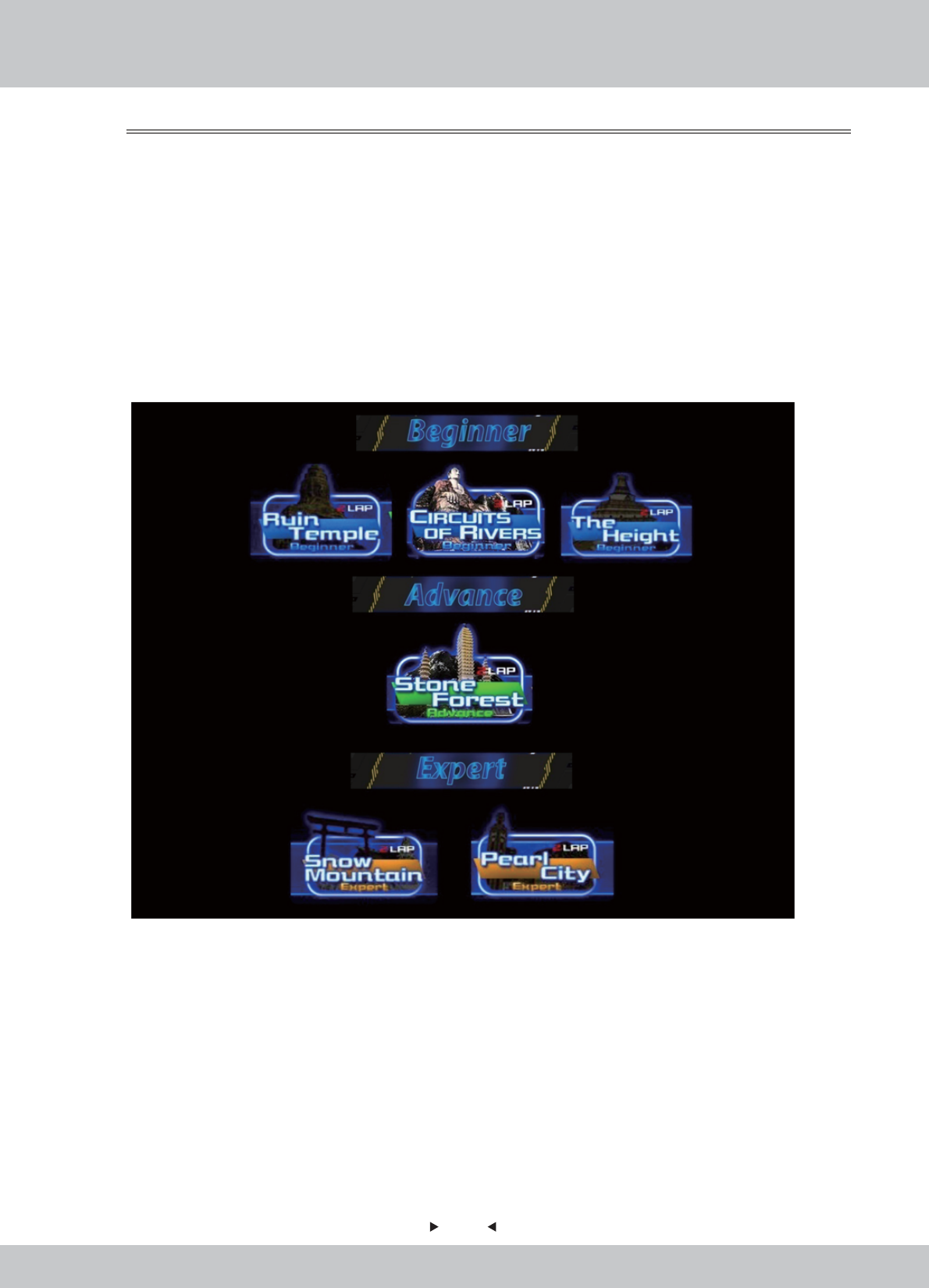
Tracks
Tracks
There are total of 12 tracks in 4 difficulties: Beginner, Advance, Expert and Extreme (appeared in
Reverse Tracks only).The game will begin with 6 Tracks –
• Circuits Of Rivers
• Ruin Temple
• The Heights
• Pearl City
• Stone Forest
• Snow Mountain
6 Hidden Tracks could be unlocked by counting how many G Coins the player has gained in every game.
4.1.2 GAME CONTENT
18
18
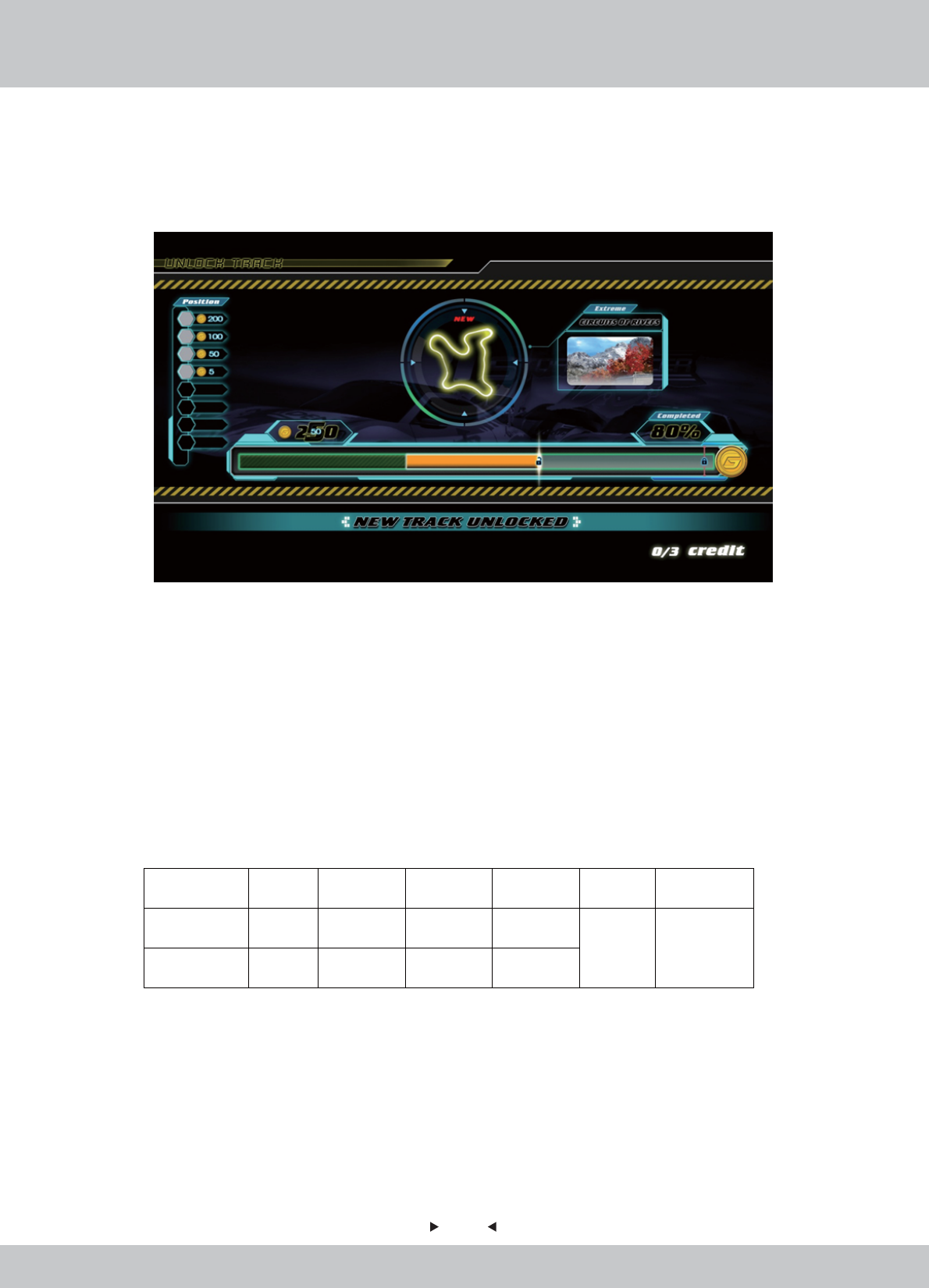
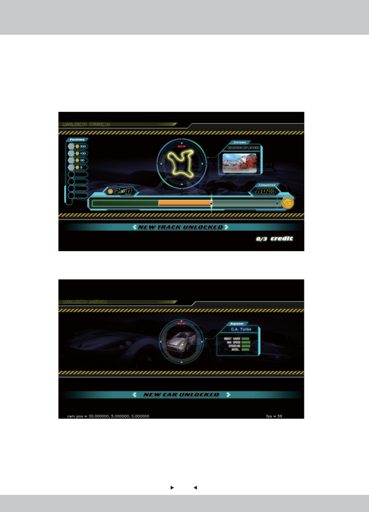
How to Unlock Hidden Tracks?
How to Unlock Hidden Tracks?
An energy bar is shown to show the player how many G Coins he has gained in the last game and how
many more he has to achieve in order to unlock certain hidden tracks.
Single-Play Mode:
Single-Play Mode:
• A new hidden track will be unlocked by counting how many G Coins the player has gained in
every game.
Multi-Play Mode:
Multi-Play Mode:
• A new hidden track will be unlocked by counting how many G Coins by all players have gained
in every multi-play game.
For example: 4players finished a game- track Circuits of River
Player Player 1 Player 2 Player 3 Player 4 Total Unlock Track
Posion 1st 2
nd 4
th 6
th
110
G Coins gained 50 30 15 15
Circults of
River
19
19
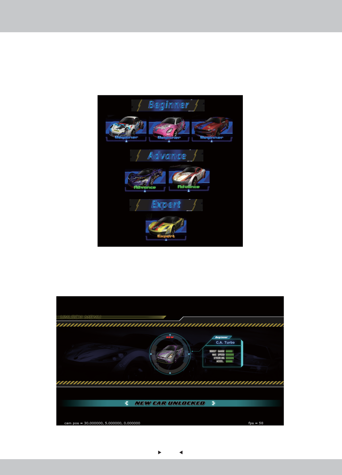
Cars
Cars
How to Unlock Hidden Cars?
How to Unlock Hidden Cars?
Single-Play Mode & Multi-Play Mode:
Single-Play Mode & Multi-Play Mode:
• A new hidden car will be unlocked in every game by random.
• 2 new hidden cars will be unlocked by The Champion in every game by random.
There are a total of 14 cars. The game will begin with 7 Main Cars.
7 Hidden Cars could be unlocked by random.
7 Main Cars are in different levels: Beginner, Intermediate and Advance
(Expert cars appeared in Hidden Cars only).
20
20
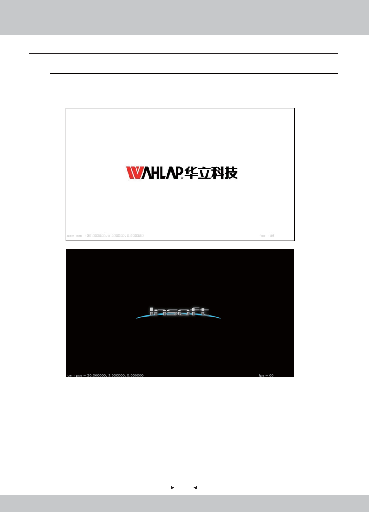
Scene 1: Logo
Scene 1: Logo
Logo of Wahlap and Insoft will be appeared in the beginning.
4.2 Game FLOW
4.2.1 Front-End MENU

21
21
Scene 2: Intro Video (with learning video)
Scene 2: Intro Video (with learning video)
The Game Introduction video will be played. Learning videos will be appeared in between.
22
22
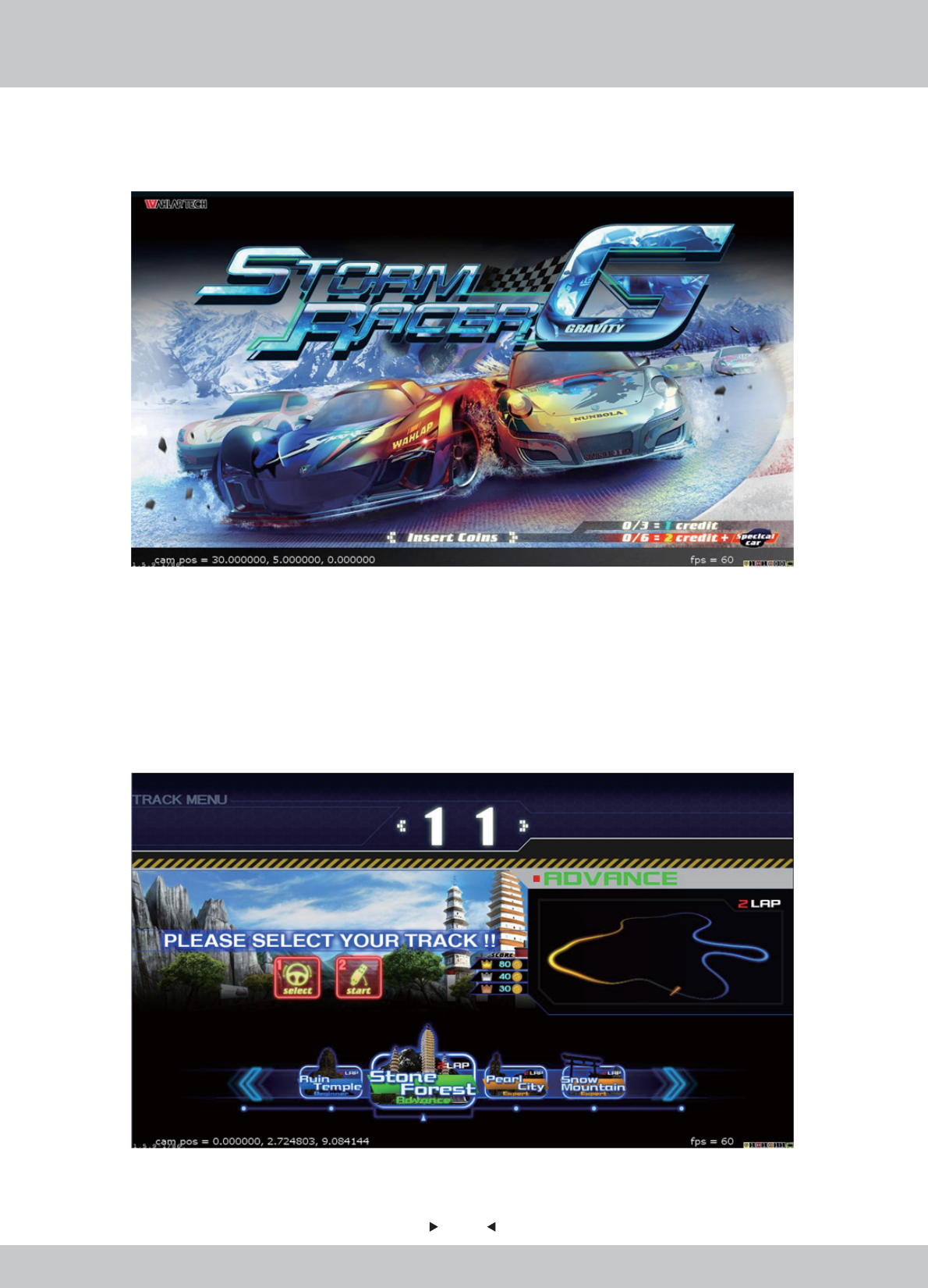
Scene 3: Insert Coins
Scene 3: Insert Coins
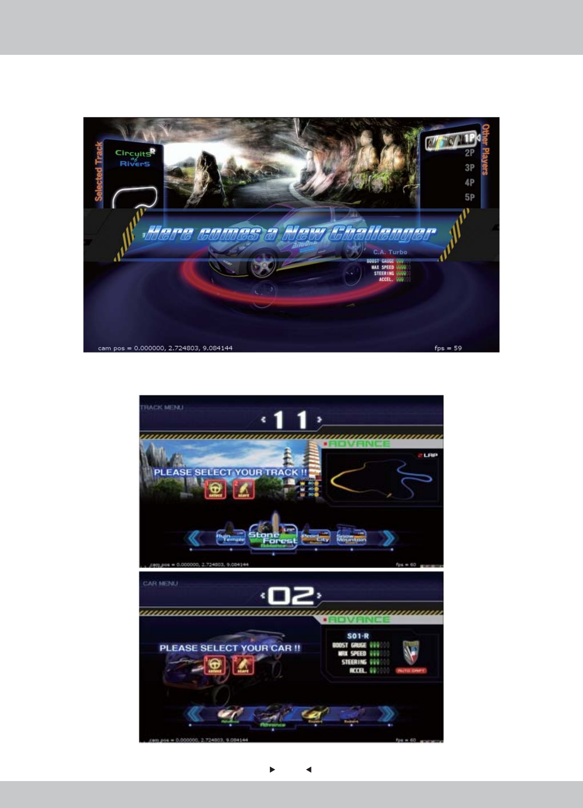
Scene 4: Selecting Track
Scene 4: Selecting Track
A screen of insert coins will appear to ask player to start the game.
In the Track Selection screen, there are a total of 12 tracks with 6 hidden tracks (to be unlocked).
Tracks are divided into four difficulty levels: Beginner, Intermediate, Superior and Extreme,
allowing players to challenge different difficulty levels.
Please use the steering wheel to turn left and right to select and then press the [START] button or
step on the accelerator.
23
23
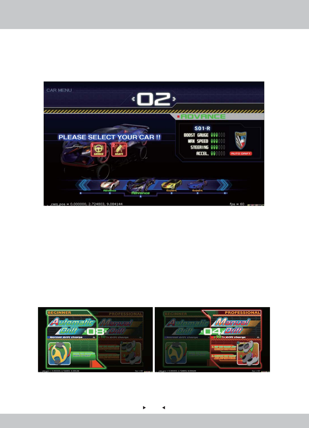
Scene 5: Selecting Car
Scene 5: Selecting Car
In the Car Selection screen, there are a total of 14 cars with 7 hidden cars (to be unlocked). Cars are
divided into three levels: Entry, Medium and Professional, drift and turn Bay deceleration is
different at different levels.
Cars are presented in four different numerical rating to show their unique performance advantages:
1: Boost Gauge (that can influence the thunderous value, the value of thunderous acceleration
forces)
2: Maximum Speed (The maximum speed in the general case)
3: Steering (there will be some advantage in a variety of Bay Road on the track)
4: Acceleration (speed of accelerate and overcome the rugged track)
Please use the steering wheel to turn left and right to select and then press the [START] button or
step on the accelerator.
Each racing car could be set Drift Mode as: Automatic Drift OR Manual Drift

24
24
Scene 6: Camera
Scene 6: Camera
Players will be invited to take icon photos which will be displayed in the race.
A photo is shot after a count down from 5 to 1.
…4…3…2…
25
25
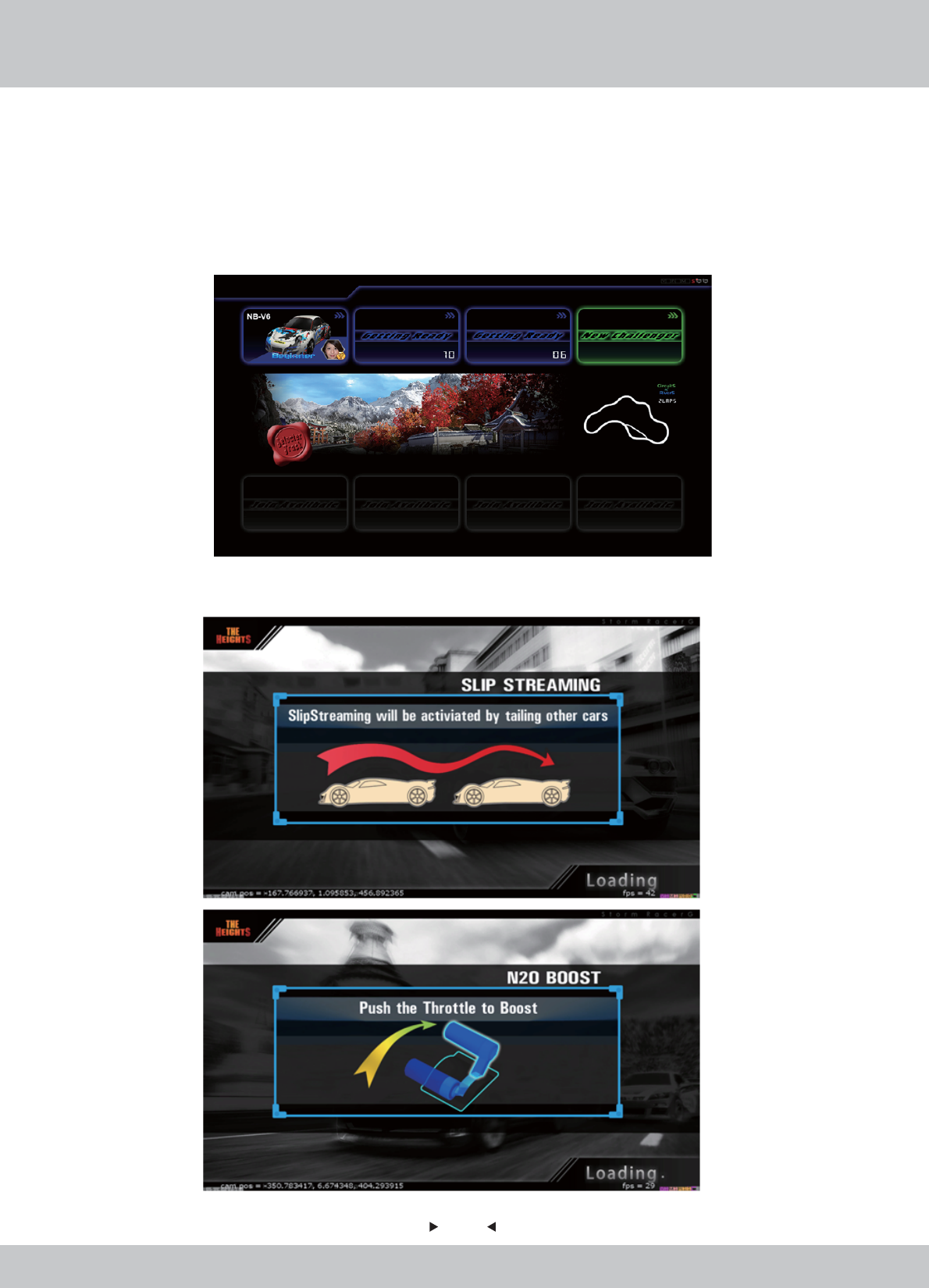
Scene 7: “Free to Join” Multi-Players Race Status Screen
Scene 7: “Free to Join” Multi-Players Race Status Screen
In a multi-player race, after selecting tracks and cars, a status screen will pop up to show the data of
each player of this race (cars selected, own photo icons, level of players).
Players who are still selecting cars will be displayed as “Getting Ready” instead of his own data.
The selected track will be displayed in the middle as well.
Scene 8: Loading Screen
Scene 8: Loading Screen
Learning Messages will be shown as loading screen.
26
26
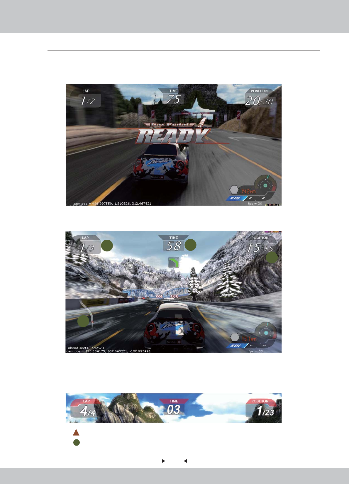
1. LAP: No. of Laps
2. TIME: Count Down (in seconds)
3. POSITION: Ranking of player
1-3 will change to RED in color in the last 60 seconds of the race.
4. Map: represents Player
represents other Players
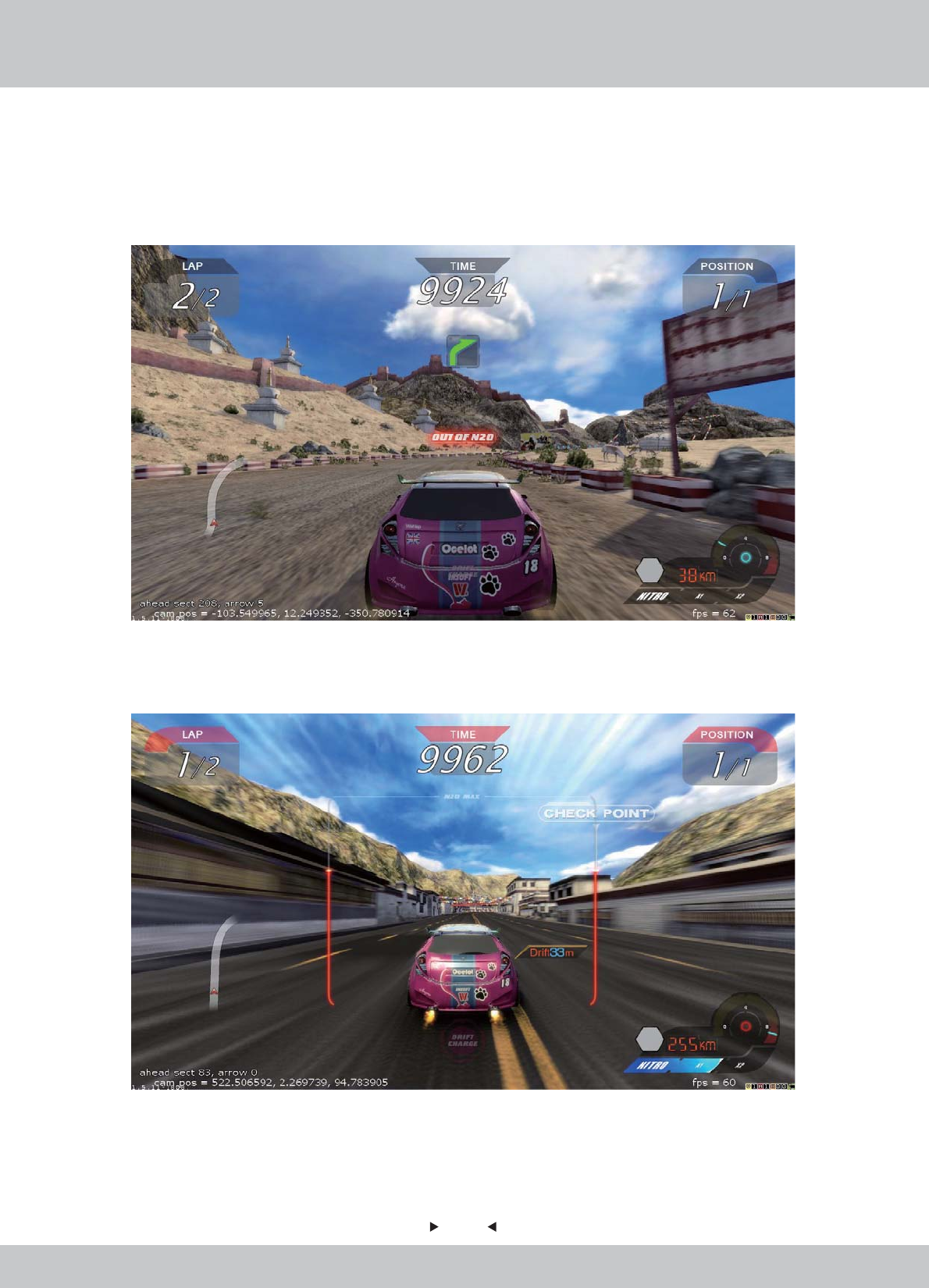
Scene 9: In-Game Screen
Scene 9: In-Game Screen
Game START
Game START
Race starts at once right after the loading is finished.
UI Screen (I)
UI Screen (I)
When the Race begins, data of the Race will be displayed around four sides of the screen.
4.2.2 In-Game MENU
12
3
4

27
27
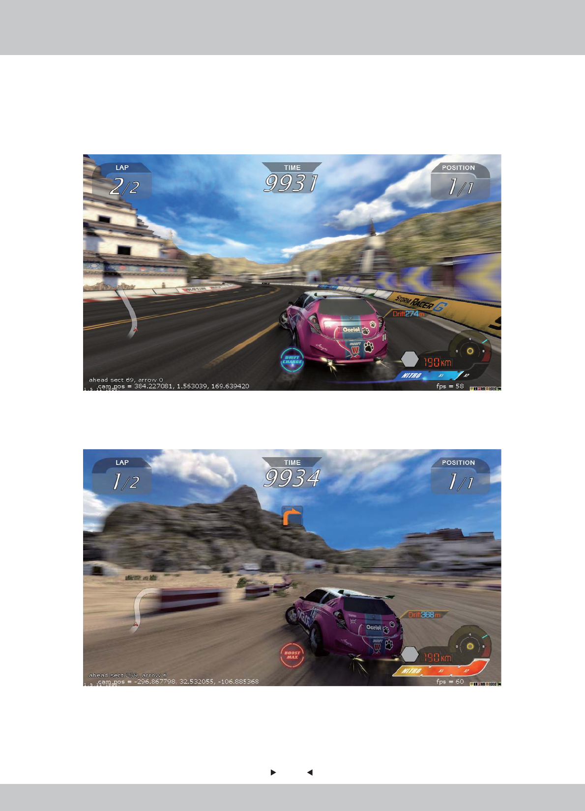
UI Screen (II)
UI Screen (II)
When the Race begins, data of the Race will be displayed around four sides of the screen.
5. Display of curve player will pass.
6. Data of player(s) in front.
7. Display of all players ranking.
8. Tips of reminding player to turn on the Nitrogen Meter Boost.
9. Data of player(s) behind.
10. Nitrogen Meter.
Status of Nitrogen Meter Boost: Normal, Charging and Full (from left to right)
5
6
7
8
910
28
28
UI Screen (III)
UI Screen (III)
“Boost Charger” status is shown at the bottom centre, displaying the status of Boost Amount.
Display 1: Boost Charger - Drift Charge.
Display 2: Boost Charger - Boost Maximum
29
29
Display 3: Boost Charger - Out of N2O
Display 4: Brackets - Using Boost (The Red Brackets drops, representing amount of N20 is
dropping when using boost)
5
30
30
Multi-Play Mode – Free Join
Multi-Play Mode – Free Join
In the first 30 seconds* of the battle, other players can join the race.
Race will start all over again if new player is joined. All players will select tracks and cars again.

31
31
Scene 10: FINISH Game
Scene 10: FINISH Game
The race is over when time is up.
Position of the player will be shown.
32
32
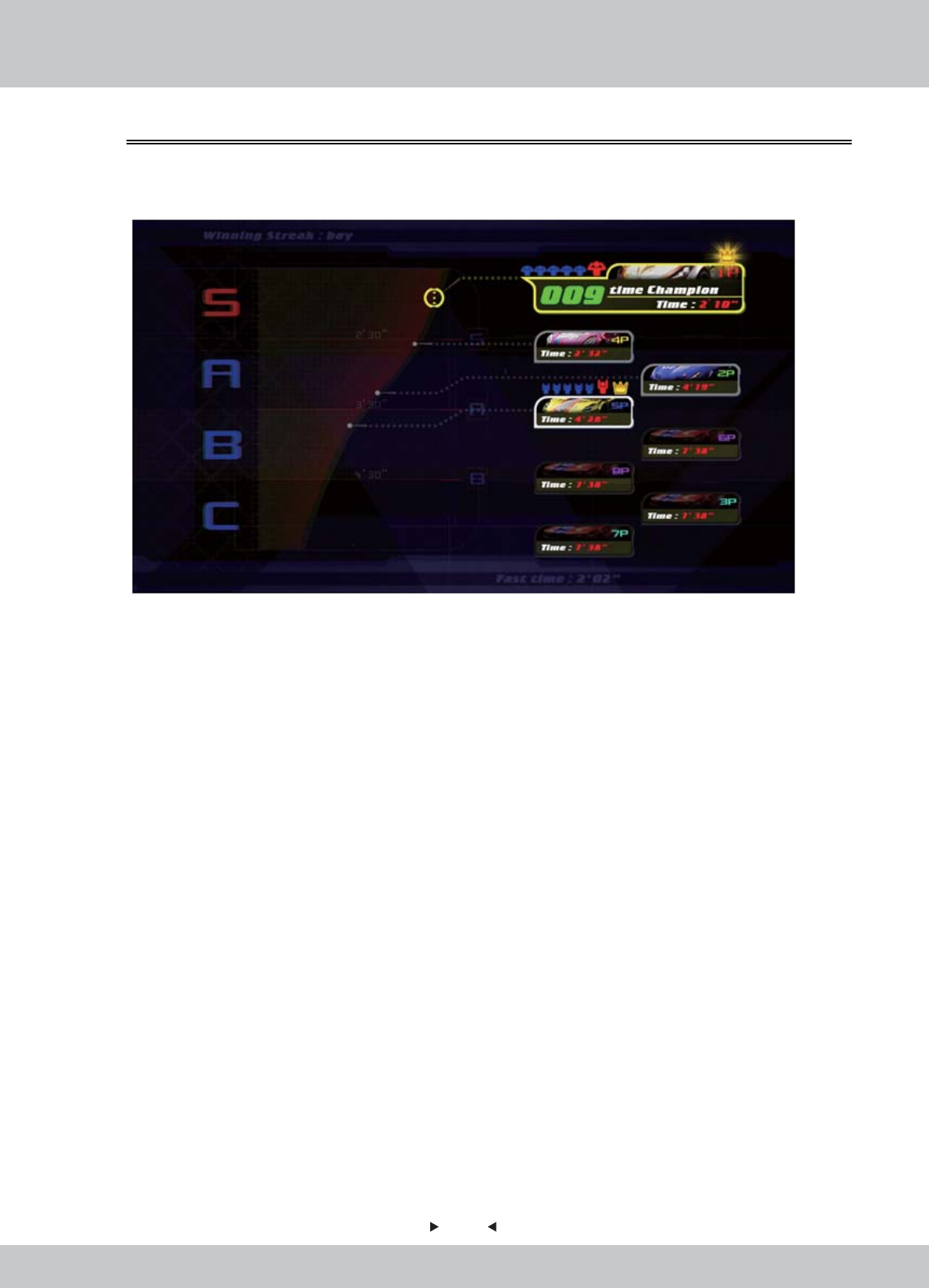
Scene 11: Race Ranking
Scene 11: Race Ranking
After the race is finished, a Final Ranking of all players will be shown.
1. Ranking of the tournament
• Levels: S 、A、 B、C
• S as the Supreme ranking; C as the lowest ranking
2. Tournament Data
a. Photo of player
b. Selected Car
c. Total Time
3. Medals obtained
4.2.3 Back-End MENU
33
33
Scene 12: Unlocked Item
Scene 12: Unlocked Item
A page of unlocked items will be shown.
Players can show if any cars or tracks have been unlocked successfully in the race they just finished.
New track is unlocked:
New car is unlocked:

34
34
Scene 13: Continue
Scene 13: Continue
-For Winner: Bonus Round (Discount Game)
-For Winner: Bonus Round (Discount Game)
-For Other Players: Game Over, Continue to Play
-For Other Players: Game Over, Continue to Play
Winner of the tournament will be awarded to continue the game with discount.
Players will be invited to continue the race to challenge and become the Winner.
35
35
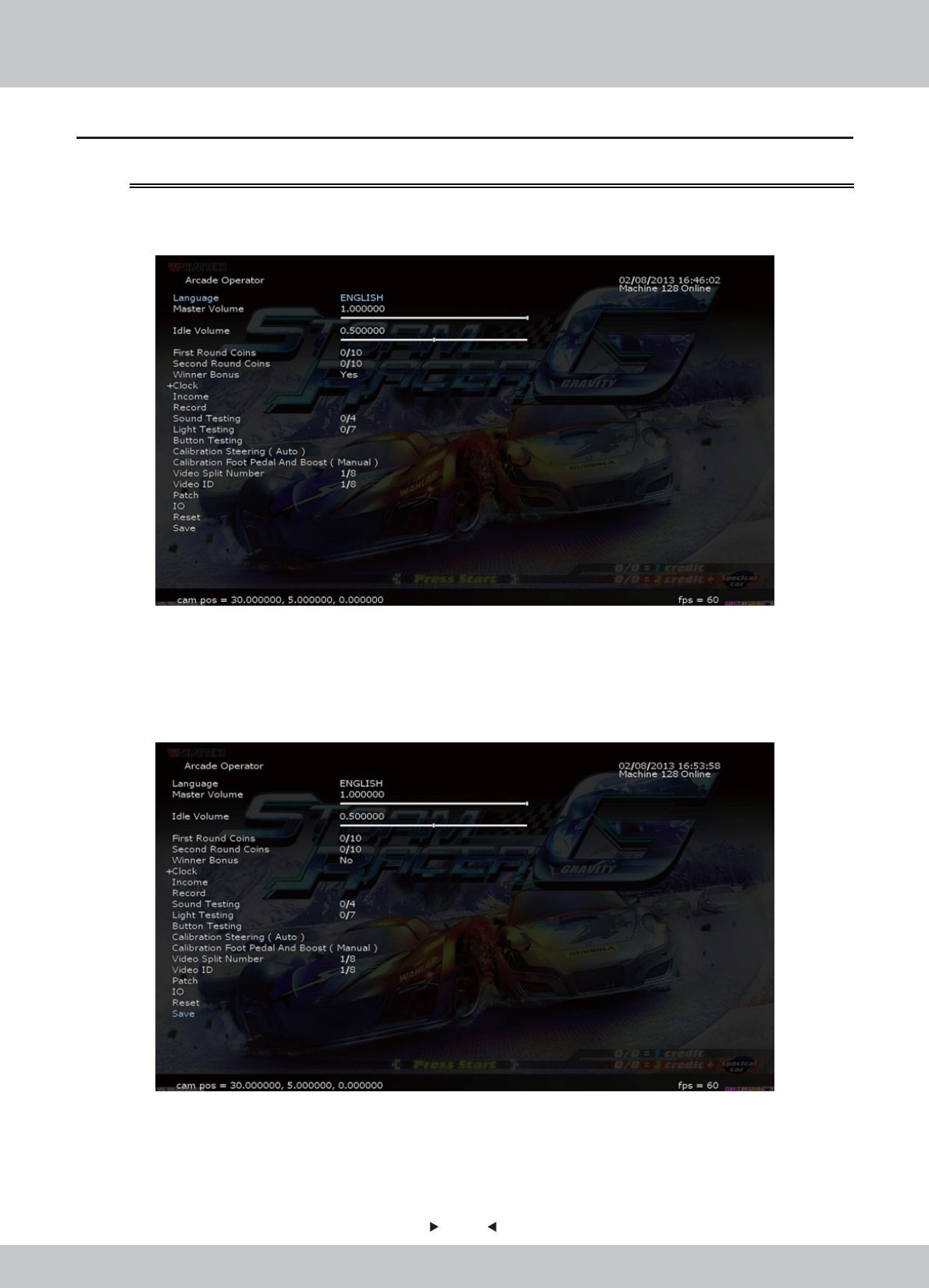
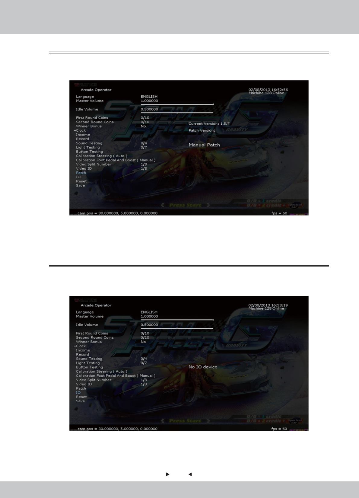
1. Under the Demo screen, press the [Test] key of the coin control box to enter the [Arcade
Operator], the main menu is shown below.
2. Enter the menu screen, use the arrow keys to select a menu item, press the [Test] key to enter
the sub-menu, follow the screen prompt message at the bottom-right side.
3. After the setup is completed, select [Save] in the main menu, then press the [START] button
or press the [services] to exit the user interface.
4.3 Operator MENU
4.3.1 Arcade Operation Mode
36
36
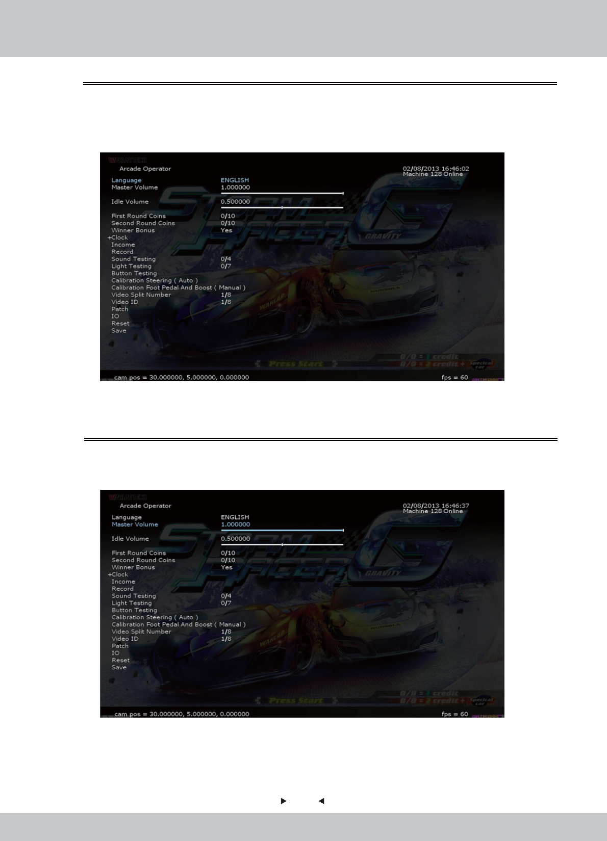
You can select the operating language in [Language].
1. Enter the [Arcade Operator] > [Language], use the left and right arrow keys to switch to the
desired language.
4.3.2 Languages
In [Master Volume], you can set the outputs of the volume of sounds by the arcade machine.
1. Enter the [Arcade Operator] > [Master Volume], the inputs of the volume are set between 0-1.
4.3.3 Master Volume
37
37
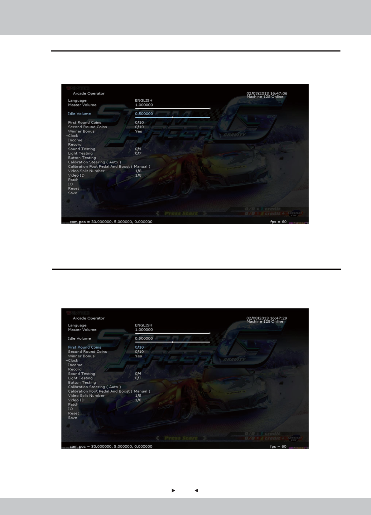
In [First Round Coins], you can set the number of coins per game need to invest per race.
1. Enter the [Arcade Operator] > [First Round Coins], the inputs of the number of coins inserted
set between 0-10.
4.3.5 First Round Coins
In [Idle Volume], you can set the outputs of the volume of sounds by the arcade machine.
1. Enter the [Arcade Operator] > [Idle Volume], the inputs of the volume are set between 0-1.
4.3.4 Idle Volume
38
38
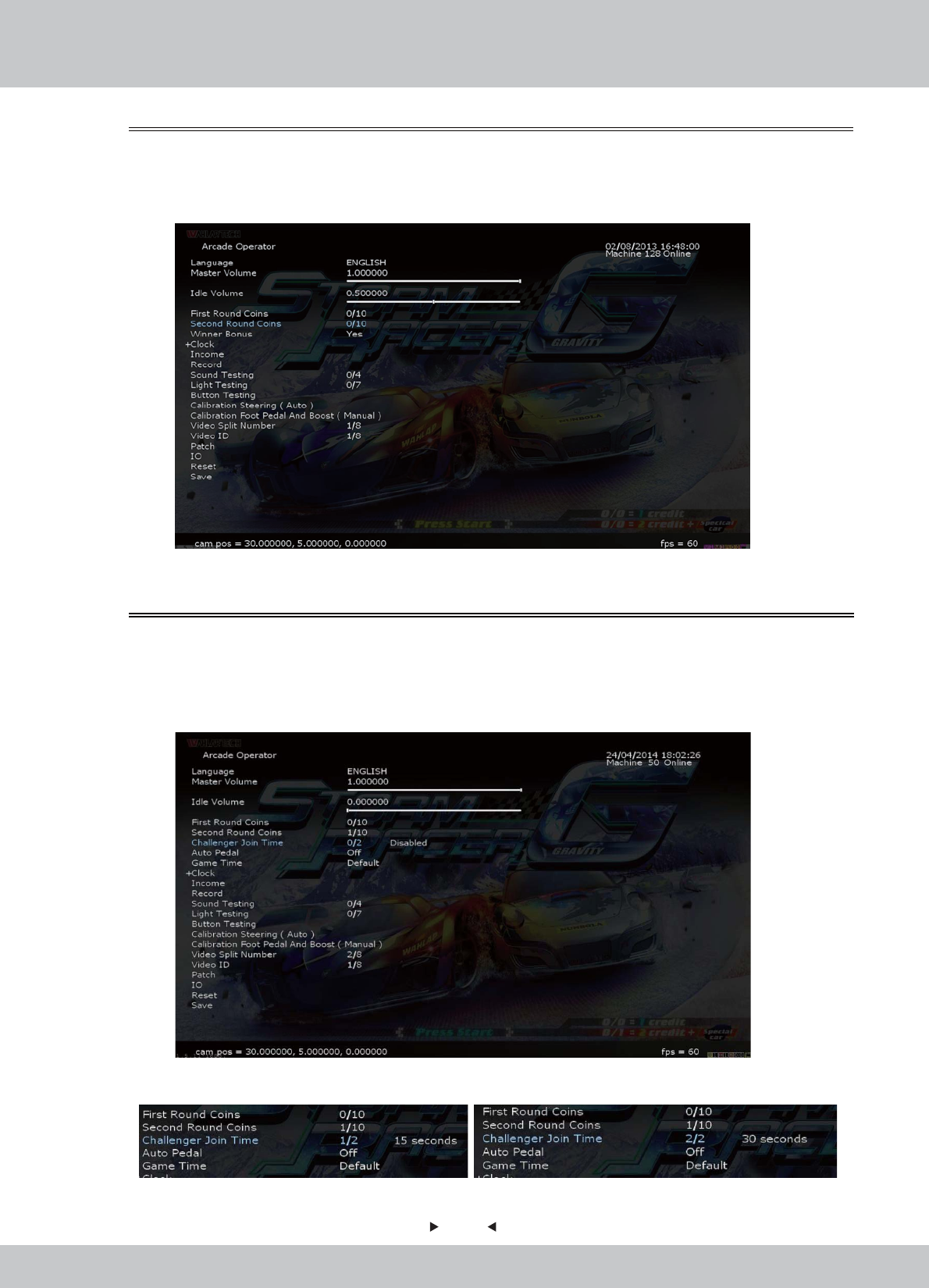
In [Challenger Join Time], you can choose whether to allow challenger to join the race or not
within 15 or 30 seconds after the race is started.
1. Enter the [Arcade Operator] > [Challenger Join Time], choose “15 seconds” or “30 seconds”
to enable challengers to join race and “Disable” to turn it off.
4.3.7 Challenger Join Time
In [Second Round Coins], you can set the number of coins per game need to invest per race.
1. Enter the [Arcade Operator] > [Second Round Coins], the inputs of the number of coins
inserted set between 0-10.
4.3.6 Second Round Coins
Can be set as: Enable 15 seconds OR 30 seconds
39
39
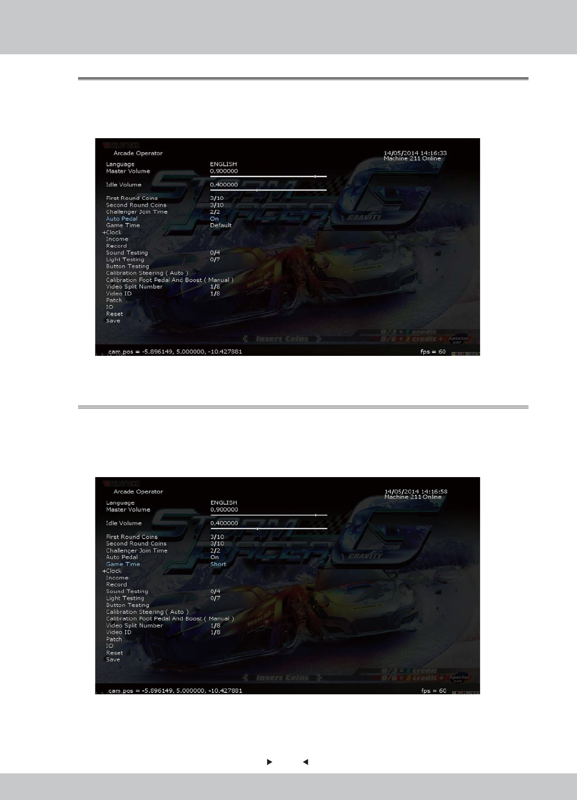
In [Game Time], you can choose whether to set the length of the game time.
1. Enter the [Arcade Operator] > [Game Time], choose “Short” to enable a shorter game time
and “Long” to enable a longer game time.
4.3.9 Game Time
In [Auto Pedal], you can choose whether to turn on the auto pedal or not.
1. Enter the [Arcade Operator] > [Auto Pedal], choose “Yes” to enable auto pedal and “No” to
turn it off.
4.3.8 Auto Pedal
40
40
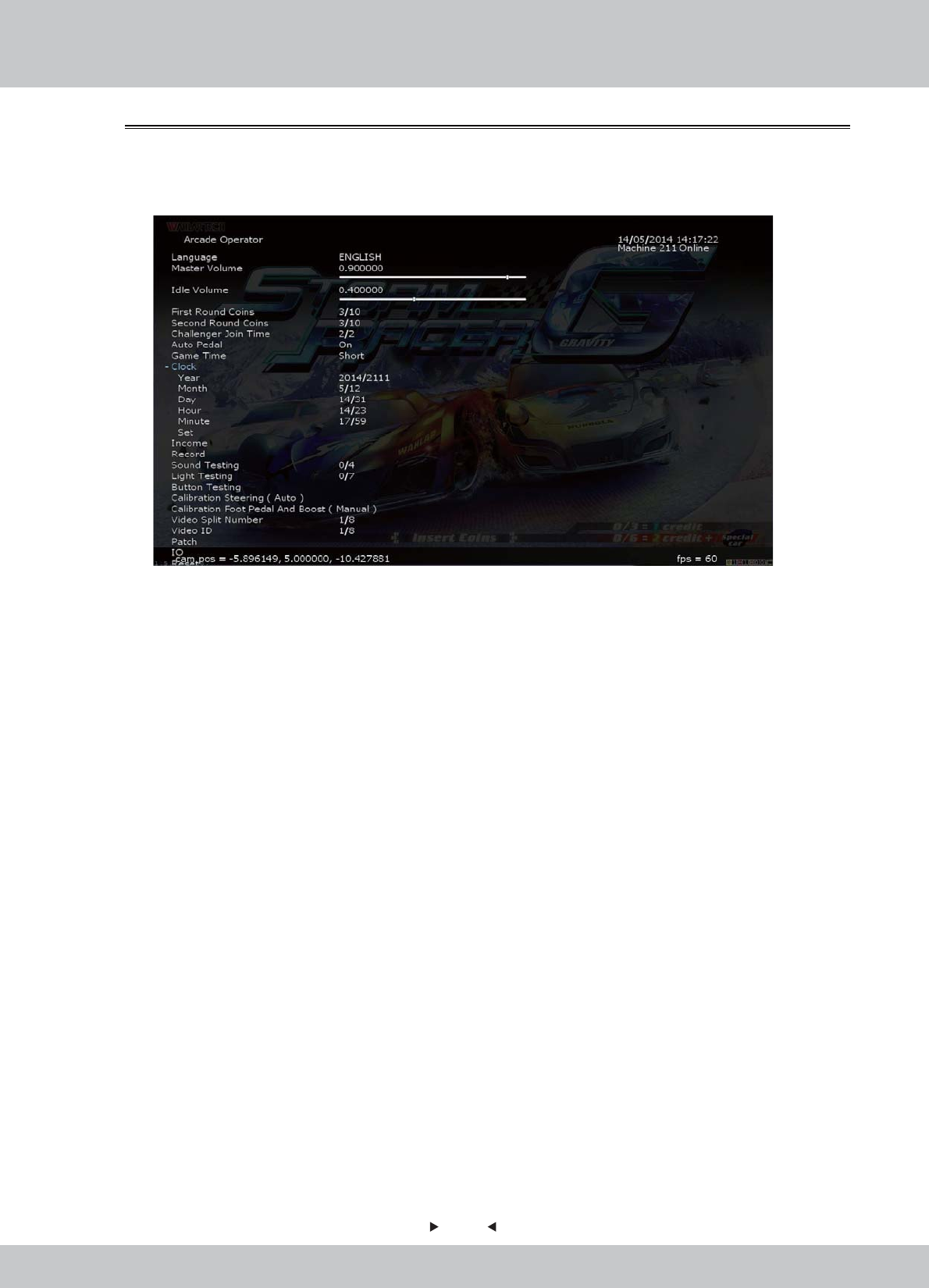
In [Clock], you can set the system time.
1. Enter the [Arcade Operator] > [Clock].
Use the arrow keys to select [Clock], and then press the [START] button to expand the
options of time setting.
2. Use the arrow keys to select the item you want to set, and then use the left and right arrow
keys to switch the setting value, after the setup is complete, select [Settings] save [Clock] is set.
3. After the setup is saved, select [Clock] again to hide the setting projects, and continue to
operate.
4.3.10 Clock
41
41
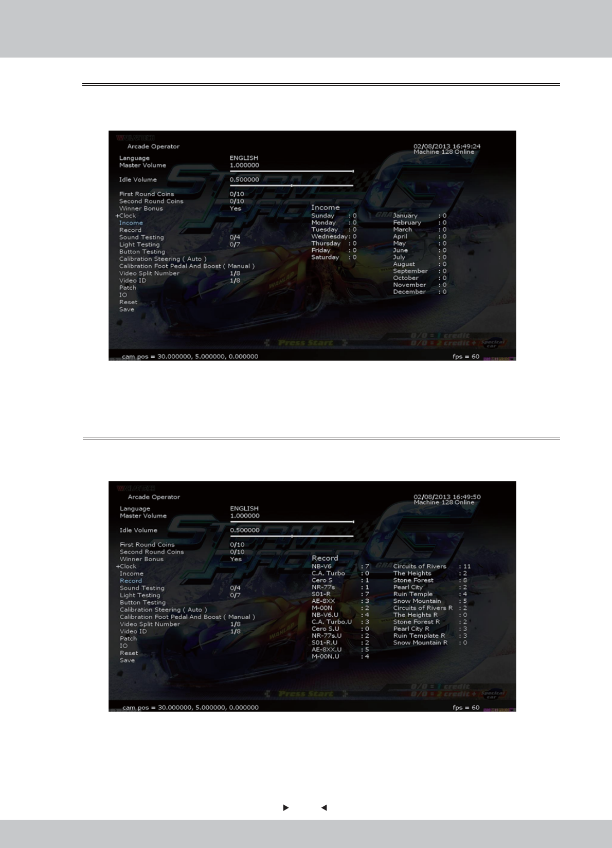
In the page [Record], you can set the machine's operating system settings.
1. Enter the [Arcade Operator] > [Record], selection screen is as follows:
• [Records] records all tournament games which have been completed.
• Left Hand Side: Vehicle models: the frequency of use
• Right Hand Side: Tracks Name: the frequency of selection
• Left Hand Side: Revenue record of the week, from Sunday to Saturday.
• Right Hand Side: Revenue record of the year, from January to December.
4.3.12 Record
In the page [Income], you can go through the revenue-related information of the machine.
1. Enter the [Arcade Operator] > [Income], selection screen is as follows:
4.3.11 Income
42
42
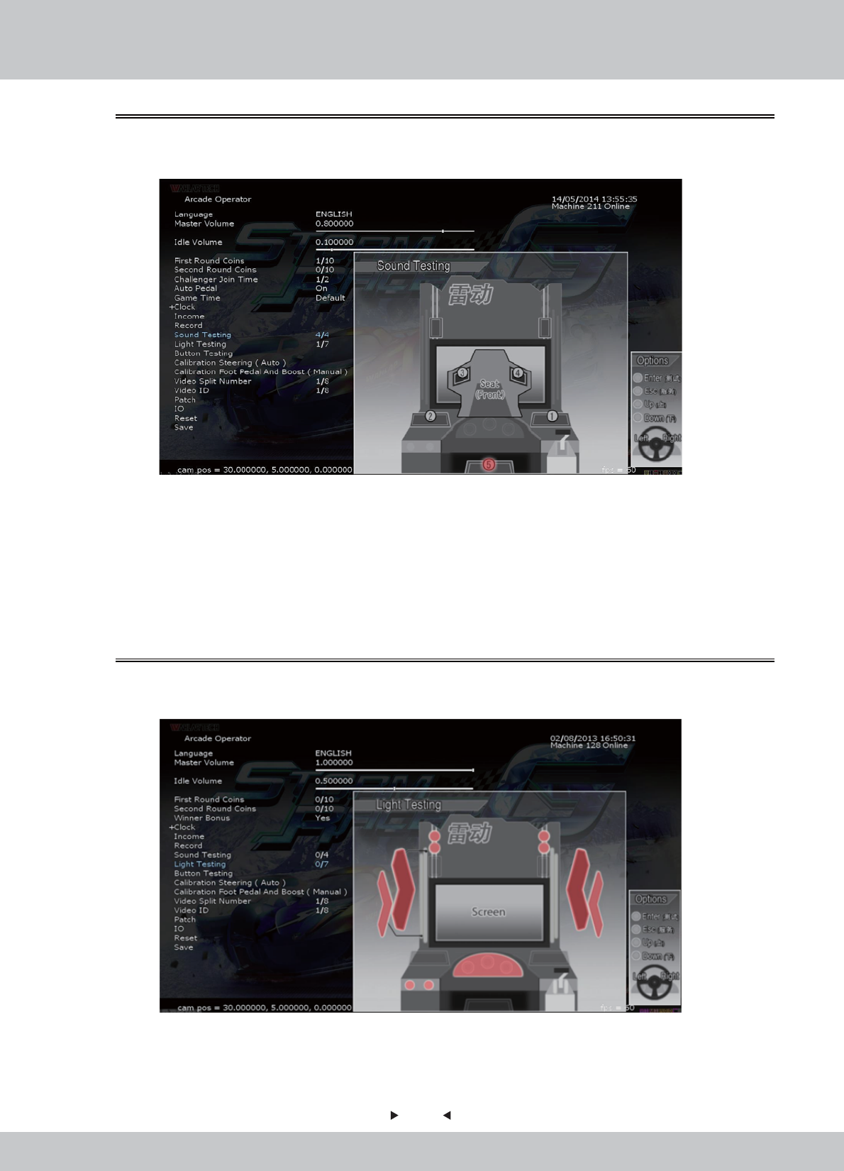
In the page [Sound Testing], you can set the machine's operating system settings.
1. Enter the [Arcade Operator] > [Sound Testing], selection screen is as follows:
2. In [Sound Testing], use the left and right arrow keys to select the item you want to test, selected
speakers (RED light) will play the test automatically and continuously.
• Normal Playback: Use the left and right arrow keys to select the set of speakers (1 to 6) you
want to test with.
• If there is no sound, check whether the volume buttons are set at the minimum level, if there
is still no sound, please operate the speaker troubleshooting.
4.3.13 Sound Testing
In the page [Light Testing], you can test if each set of lights (1 to 7) is in normal condition.
1. Enter the [Arcade Operator] > [Light Testing], selection screen is as follows:
2. In [Light Testing], use the left and right arrow keys to select the item you want to test.
• This test can operate a total of eight options, from 0-7.
• The selected item (RED light) will automatically light for testing.
4.3.14 Light Testing
43
43
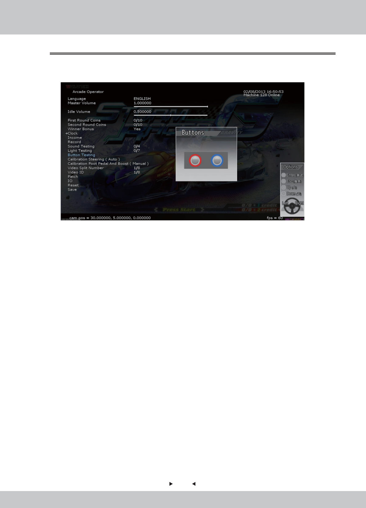
In the page [Button Testing], you can test if buttons are in normal condition.
1. Enter the [Arcade Operator] > [Button Testing], selection screen is as follows:
2. In [Button Testing], use the left and right arrow keys to select the item you want to test. This
test has a total of four options.
• [START] button y function
• [VIEW] button function
• Accelerator handle - Push function
• Accelerator handle - Pull function
3. Press the button which is needed to be tested, the button displayed on the screen will light up
in RED for normal condition.
4.3.15 Button Testing
44
44
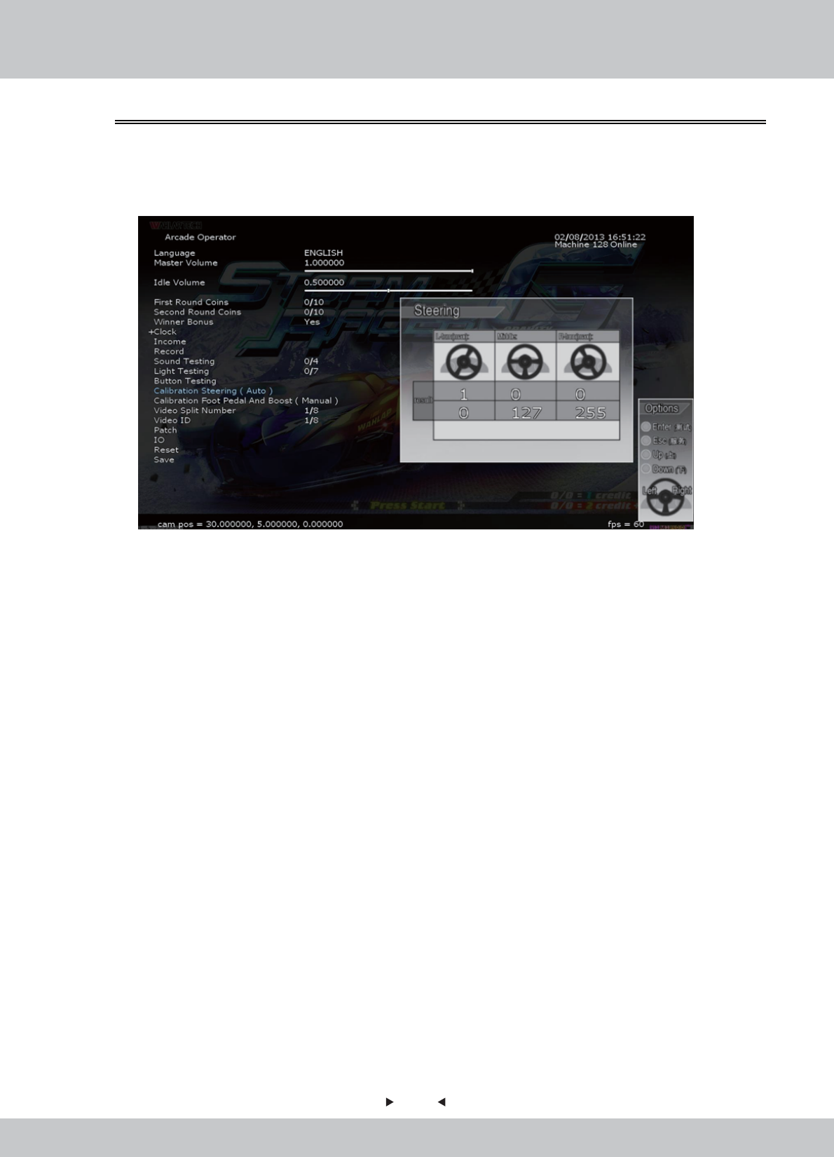
In the page [Calibration Steering (Auto)], you can test and proofread the sensitivity of the steering
wheel and handling.
1. Enter the [Arcade Operator] > [Calibration Steering (Auto)], selection screen is as follows:
2. In [Calibration Steering (Auto)], the steering wheel will calibrate automatically to show the test value.
• This calibration project is divided into three categories:
Left in Most-Valued: Left-turn torque of the steering wheel
Center: the steering wheel in the median position;
Right in Most-Valued: Right-turn torque of the steering wheel
3. When turning the steering wheel, numerical changes with the rotation rate. When turning to the
Most-Right, the indicated value is about 255; 0 when turning to the Most-Right.
4. The value of the steering wheel is displayed in the Calibration Result column. The First column
is the Actual-calibrated value; the Second column is the Ideal-calibration value.
5. The calibration value must be in the range of 5% of the ideal value, or criticized as sub-standard.
6. The lowest column will be displaying the Rating Symbol:
“ ” tick as qualified; " " cross as sub-standard, adjustment is required.
4.3.16 Calibration Steering (Auto)
✔X
45
45
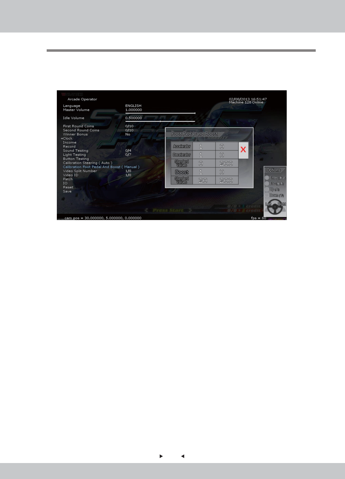
2. There are two projects in this calibration operation:
• Throttle: By stepping the throttle, the value will be changed. By stepping the throttle to the most, the
value should be around 255; If the throttle is not be stepped, the value should be around 0.
• Brake: By stepping the brake, the value will be changed. By stepping the brake to the most, the value
should be around 255; If the throttle is not be stepped, the value should be around 0.
3. The maximum and minimum values of the throttle and brake should be within 10% of the ideal
value.
The lowest column will be displaying the Rating Symbol:
“ ” tick as qualified; " " cross as sub-standard, adjustment is required.
In the page [Calibration Foot Pedal (Manual)], you can test and proofread the sensitivity of the
foot Pedal.
1. Enter the [Arcade Operator] > [Calibration Foot Pedal (Manual)], selection screen is as follows:
4.3.17 Calibration Foot Pedal and Boost (Manual)
✔X
46
46
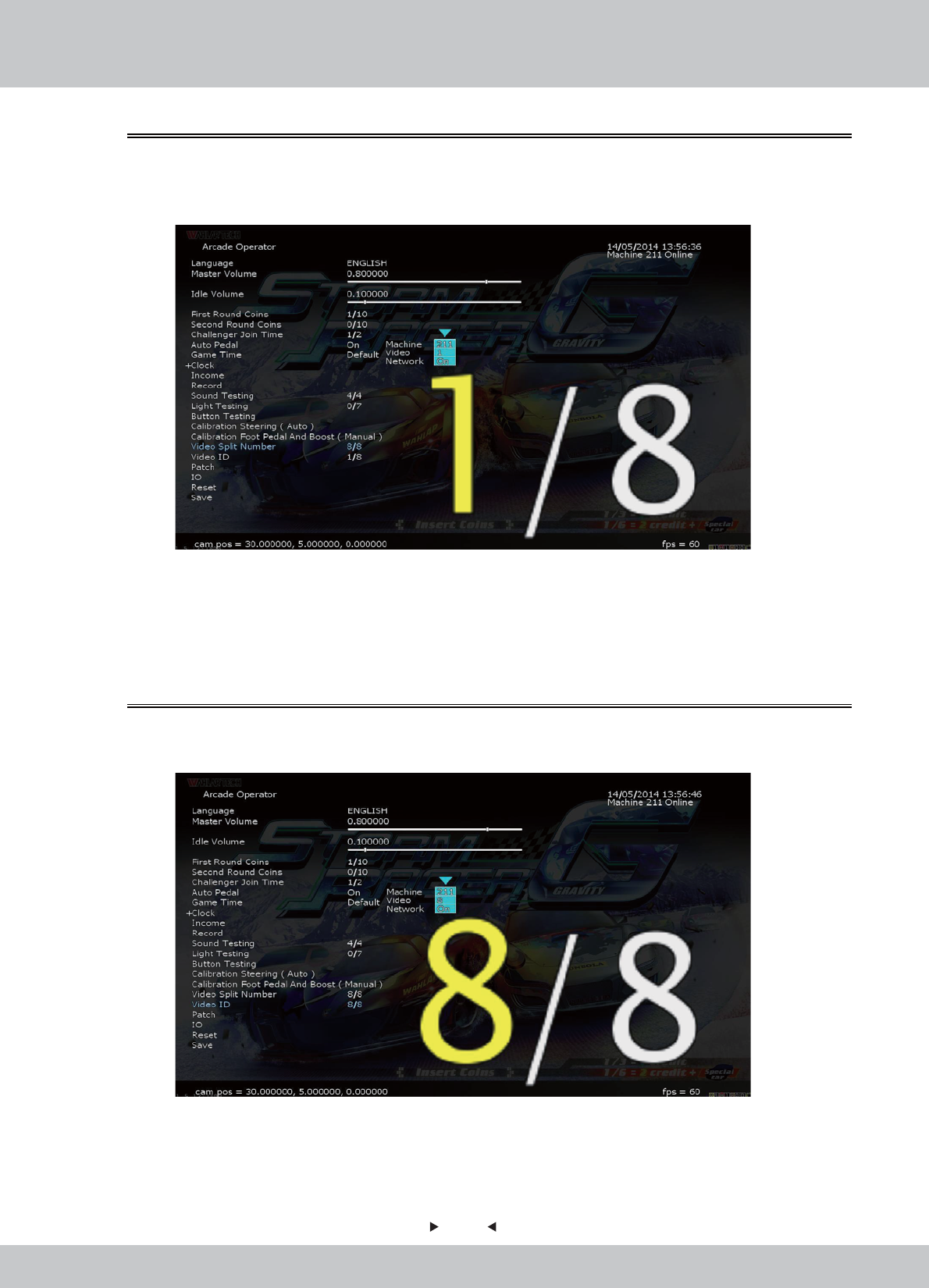
In the page [Video Split Number], you can choose how many machines you want to split the
video as display.
1. Enter the [Arcade Operator] > [Video Split Number], selection from 1 to 8 machines.
2. There are three displays in this operation:
• Machine: The machine number.
• Video: The sequence of video in the machine.
• Network: The network status: On or Off
2. There are three displays in this operation:
• Machine: The machine number.
• Video: The sequence of video in the machine.
• Network: The network status: On or Off
4.3.18 Video Split Number
In the page [Video ID], you can set the video ID of the machine.
1. Enter the [Arcade Operator] > [Video ID], selection from 1 to 8 machines.
4.3.19 Video ID
47
47
In the page [Patch], you can do the patching.
1. Enter the [Arcade Operator] > [Patch], selection screen is as follows:
4.3.20 Patch
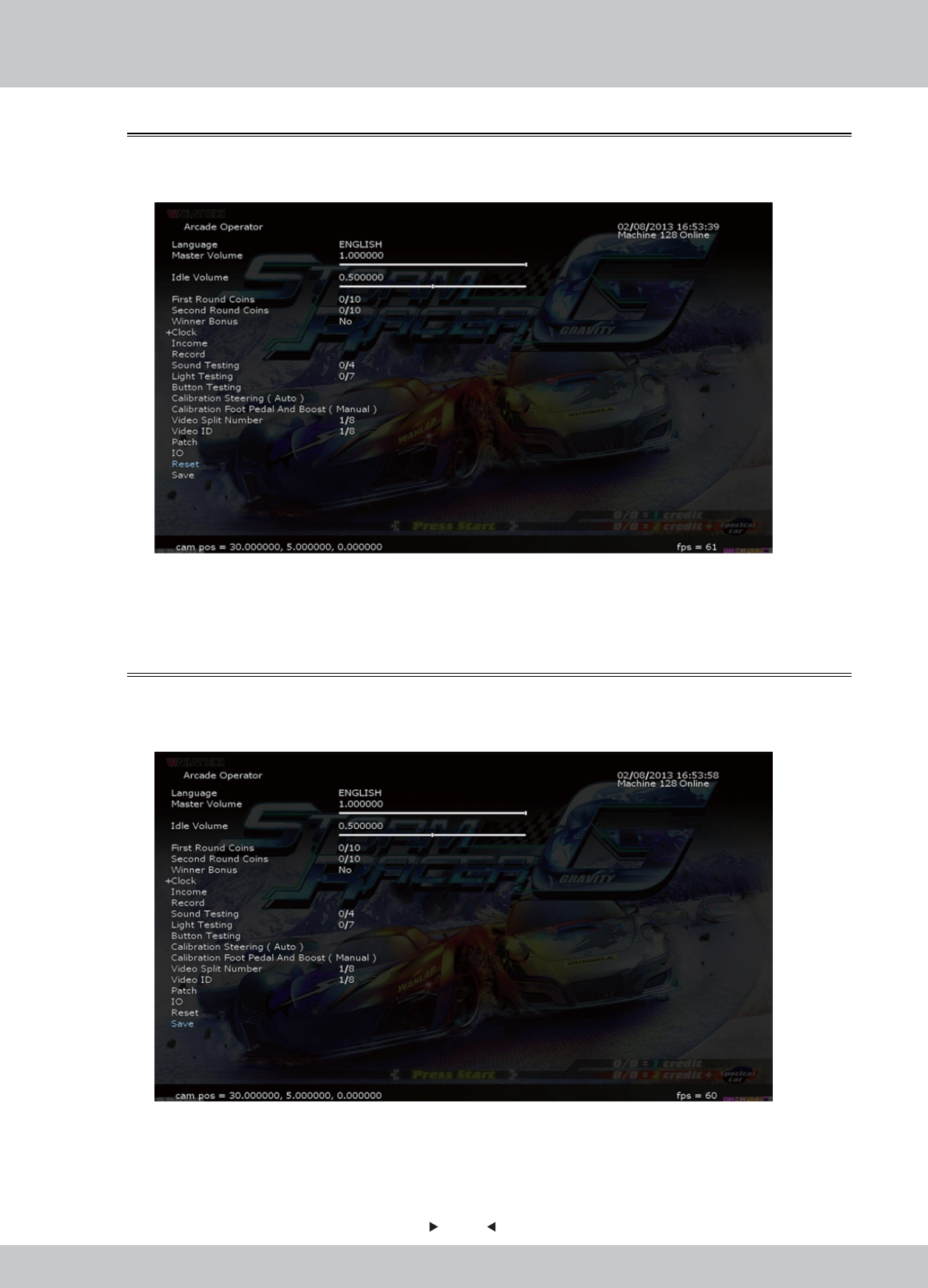
In the page [IO], you can check if there is any IO device.
1. Enter the [Arcade Operator] > [IO], selection screen is as follows:
4.3.21 IO
48
48
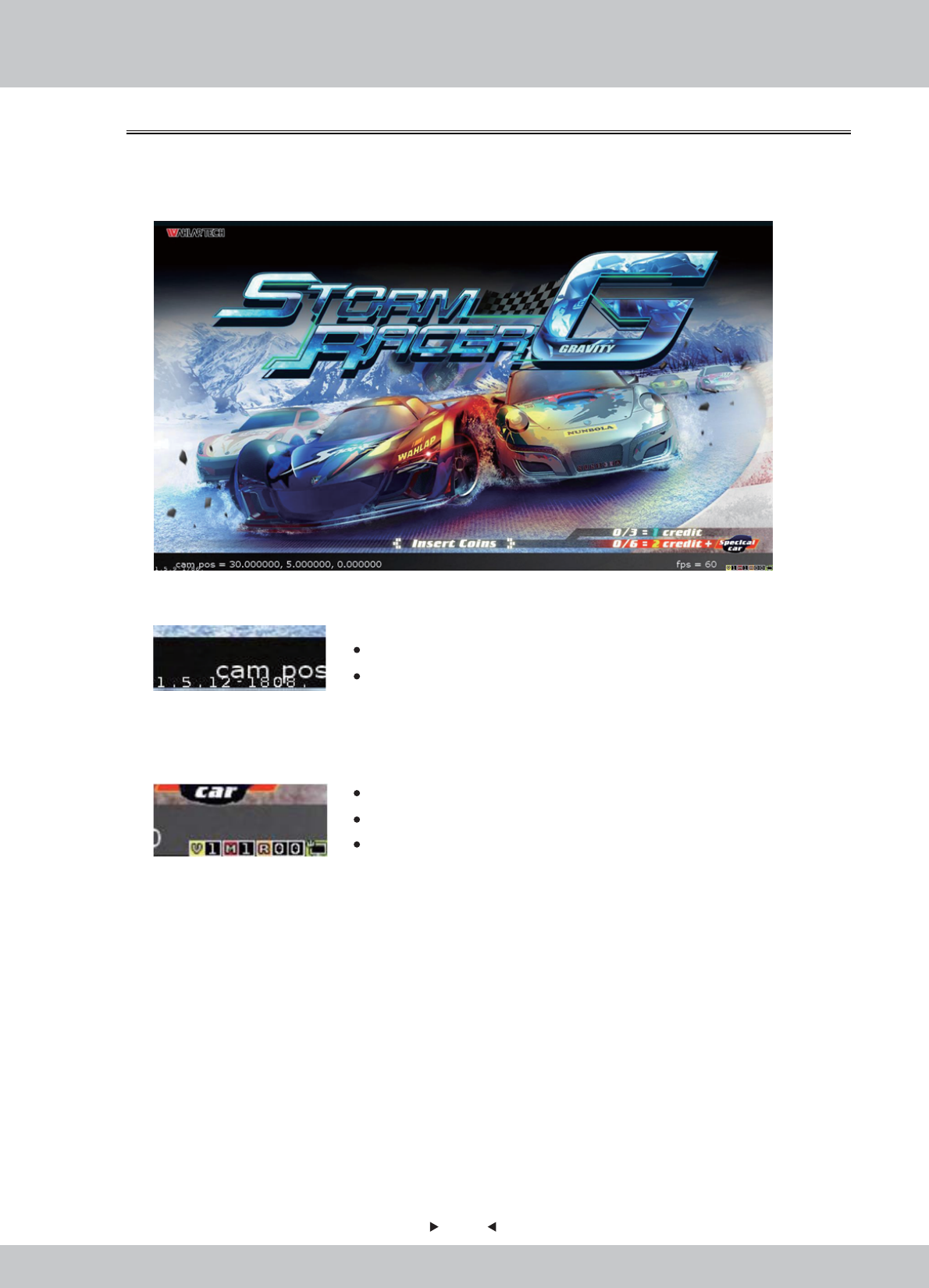
In the page [Reset], you can set up to restore all settings to the original settings.
1. Enter the [Arcade Operator] > [Reset], selection screen is as follows:
4.3.22 Reset
In the page [Save], you can save all the settings in the setup.
1. Enter the [Arcade Operator] > [Save], selection screen is as follows:
2. Select [Save] and then press the [START] button, all settings will be saved.
2. Select [Reset] and then press the [START] button in the arcade. All settings will be restored to
default, all arcade records will be cleared.
4.3.23 Save
49
49
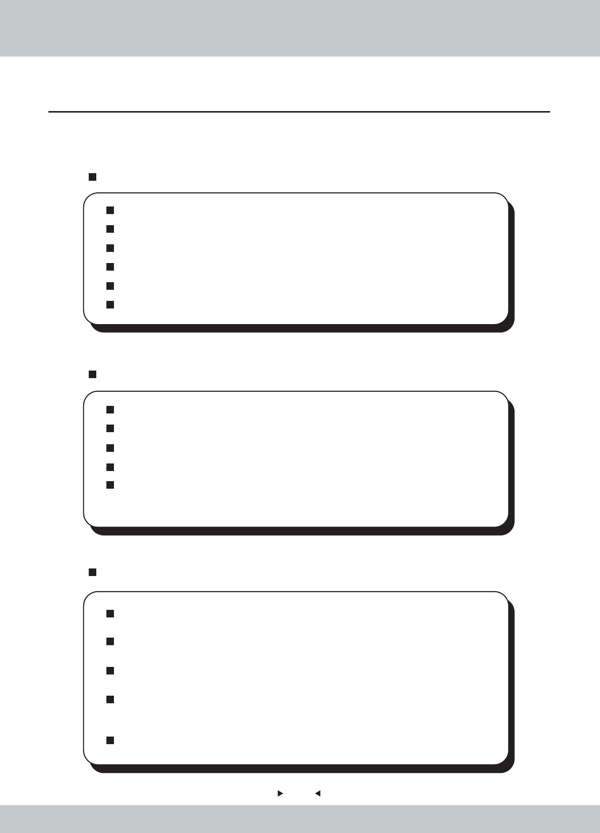
In the below of the [Game-Play screen], 2 pieces of information about the game and machine is
shown.
1. Down Left-corner.
2. Down Right-corner
Main Version: 1.5.12
Build Version: 1808
4.3.24 Game-Play Screen Information
V – Video ID: 1
M – No. of machines connected LAN: 1
R : (for development purpose)
50
50
Even though the machine works normally for a long time, the fault will occur. Therefore,
please perform routine check and maintenance concerning the following to ensure a
long-term use.
External Inspection
Stick “Warning” stickers correctly, keep it legible.
Firmly tighten the bolt for each adjuster.
Tighten screws for speaker assembly.
Tighten the signboard firmly.
Check if the screws fixing the parts loose.
Check if the connectors loose or missing.
Operation Inspection (With power on)
Sound is normally emitted from the speakers or not.
Fluorescent lamps and button lamps light up or not
Coin acceptor works properly or not.
Lifting and falling devices work properly or not.
YZ sensor works properly or not.
After completing all the checks, operate the game again and check the above
items with full care!
Servicing (conducted by a technician only)
Cut off the main power supply to avoid injury or electric shock when performing
maintenance.
Please contact our service center when performing any work that is not specified in this
Manual, and follow the instruction provided by the service center.
For consumables and spare parts (including screws), please use products specified by
Wahlap Technology.
Even though the main power is cut off, there is still high temperature and high pressure
in the power board and the monitor. The person will be burnt or get an electric shock if
he touches such parts. Please pay full attention to avoid contact.
Be sure to cut off the main power when you alter a spare part or unplug a connector.
5. Maintenance and Service
5.1 Maintenance and service
51
51
5.2 Part Replacement
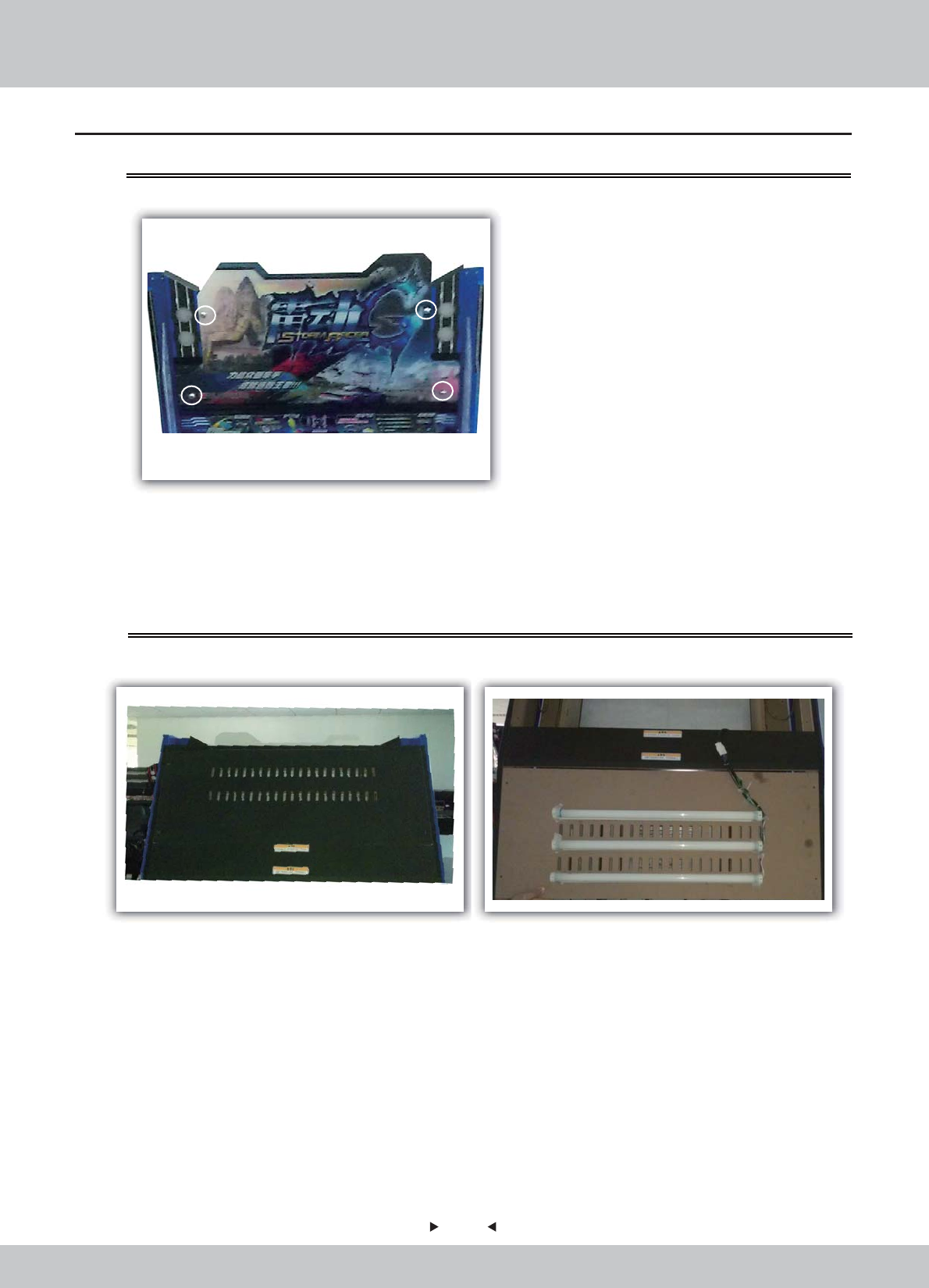
5.2.1 Replacement of acrylic signboard
5.2.2 Replacement of fluorescent plate
1.Remove the screws on the acrylic signboard for replacement.
1. Open the back door shown in the figure.
2. Reverse the opened back door and find the fluorescent tube requiring being replaced
for replacement.
52
52
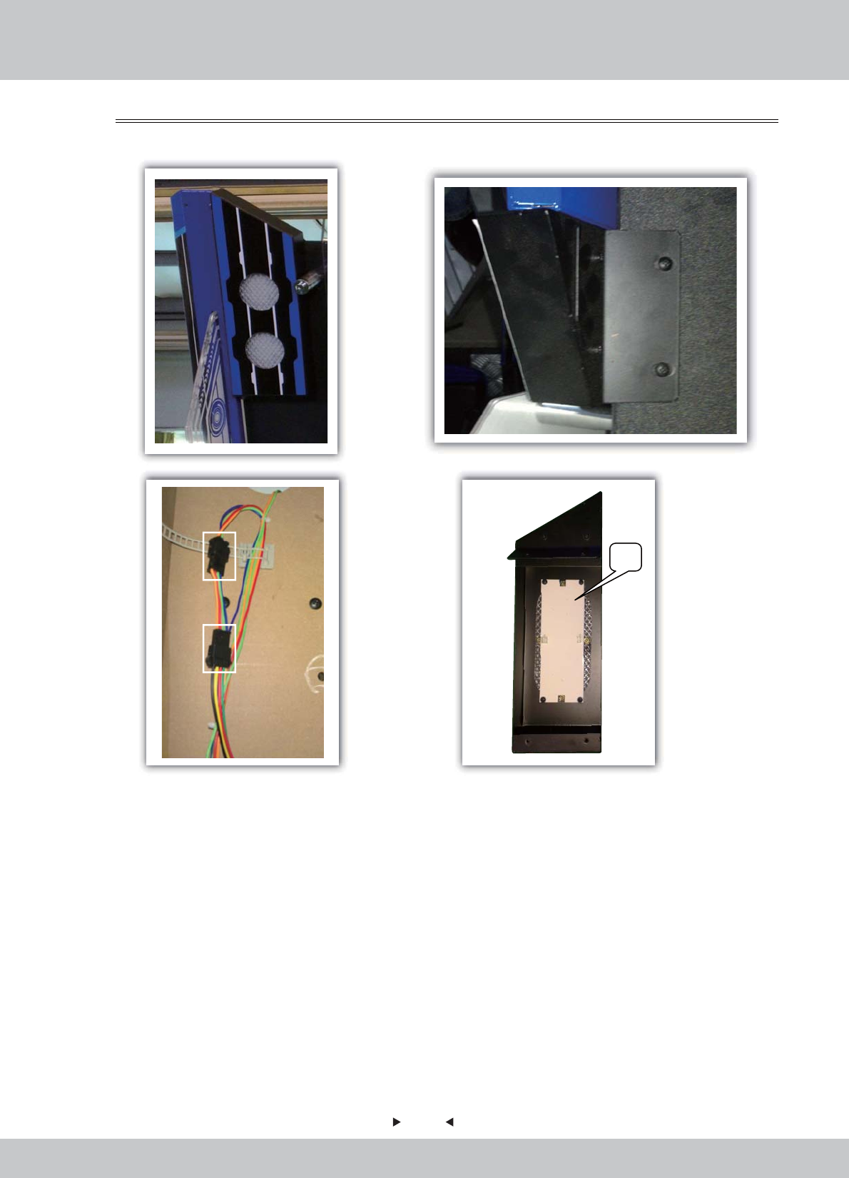
1. After removing the screws used to fix the light box on the top of the machine,
open the back door of the machine.
2. Find the connecting wire of the light box, pull out the rubber seat terminals and
remove the light box.
3. Remove the fluorescent plate on the light box for replacement.
5.2.3 Replacement of top light box
LED
53
53
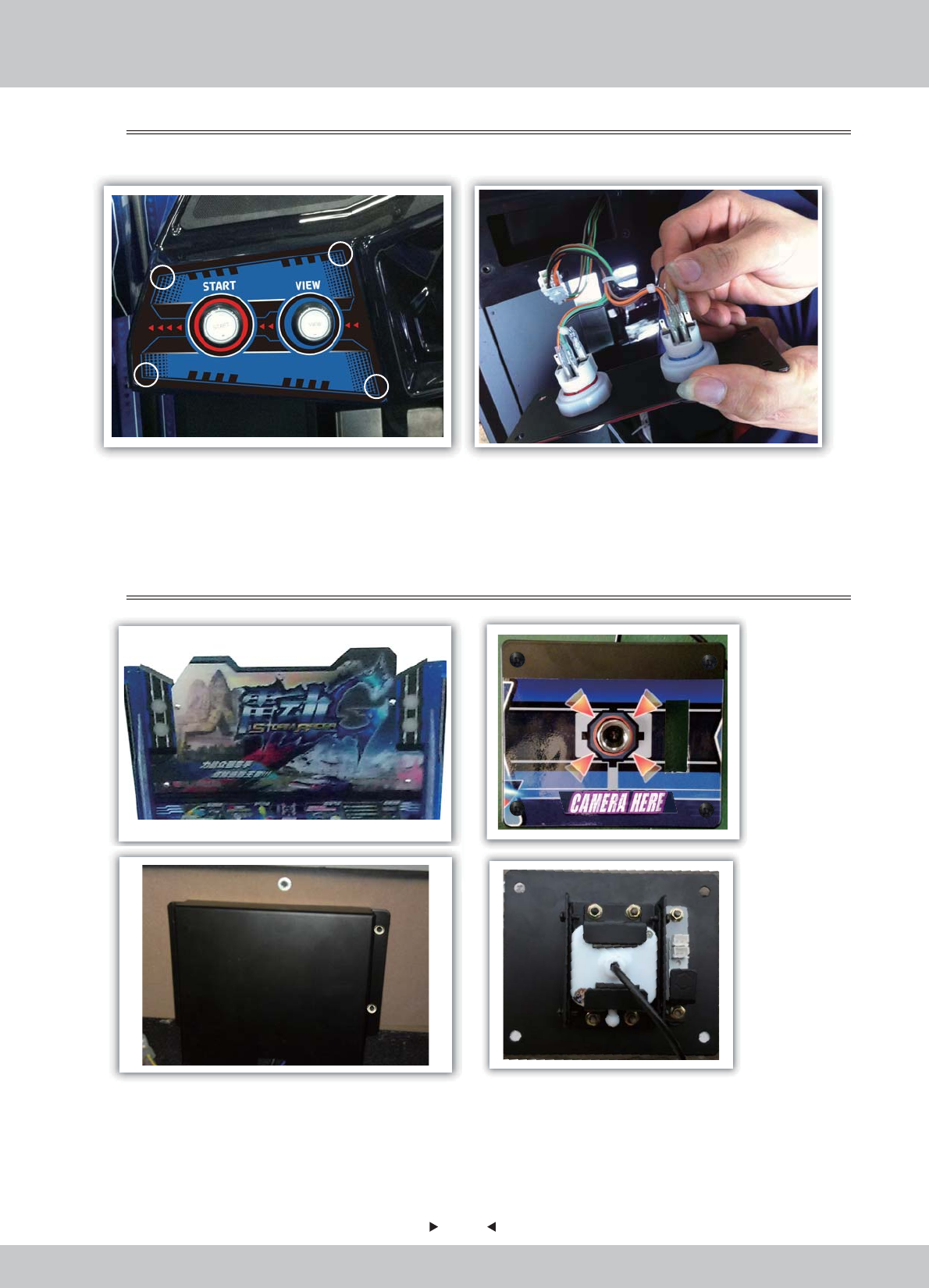
1. Remove the fixing screws of key board.
2. Remove the keyboard, pull out the terminals and replace the key.
5.2.4 Key replacement
1. After removing the acrylic panel, remove the fixing screws on the pick-up head.
2. Open the back door and remove the fixing screws on the rear cover of the pick-up head.
3. Remove the pick-up head and fixing components and replace the pick-up head after
removing the fixing screws.
5.2.5 Replacement of pick-up head
54
54
1. Remove the fixing screws with the slotted screwdriver, take out the stop plate, remove
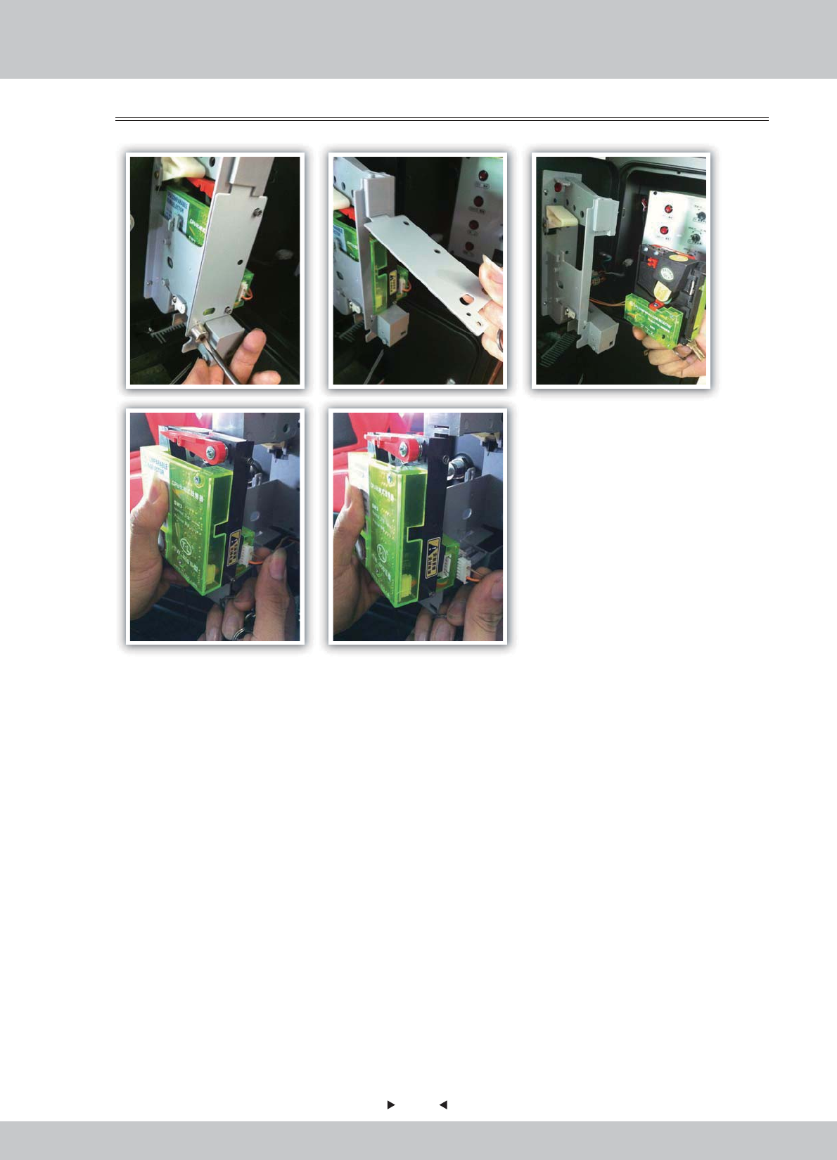
the coin acceptor, pull out the terminals and replace the coin acceptor.
5.2.6 Replacement of coin acceptor
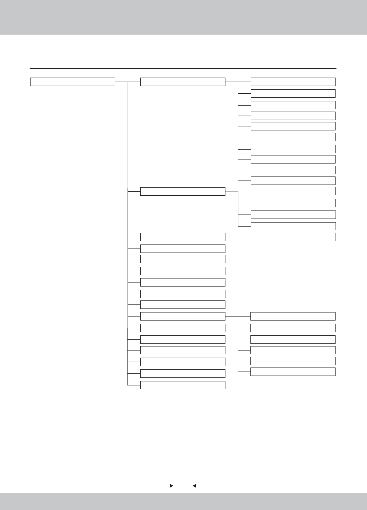
6.1 Assembly tree diagram
55
55
6. Assembly
- --
---
-
-
-
-
-
-
--
-
---
-
----
----
--
-
-
-
-
-
-
--
--
--
-
-
-
--
--
--
---
--
--
--
-
--
--
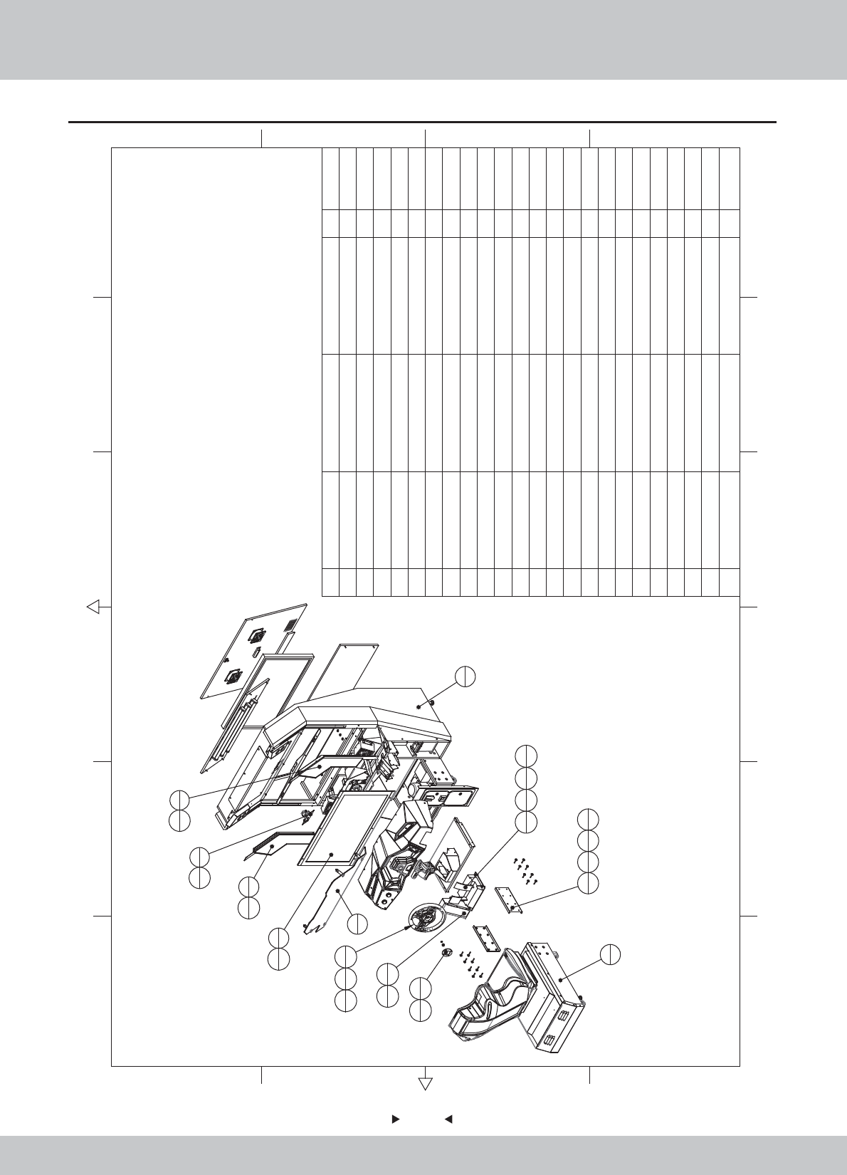
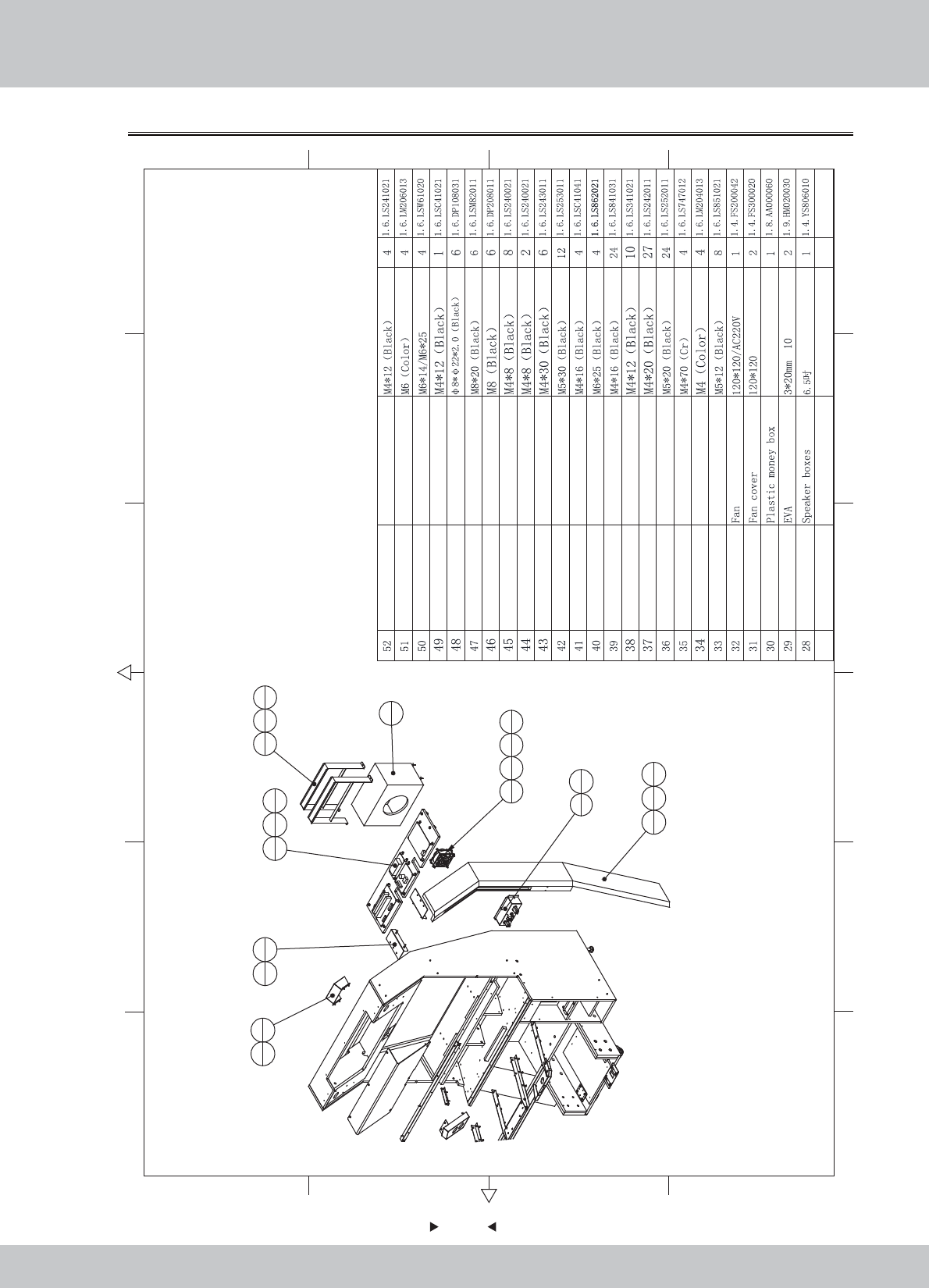
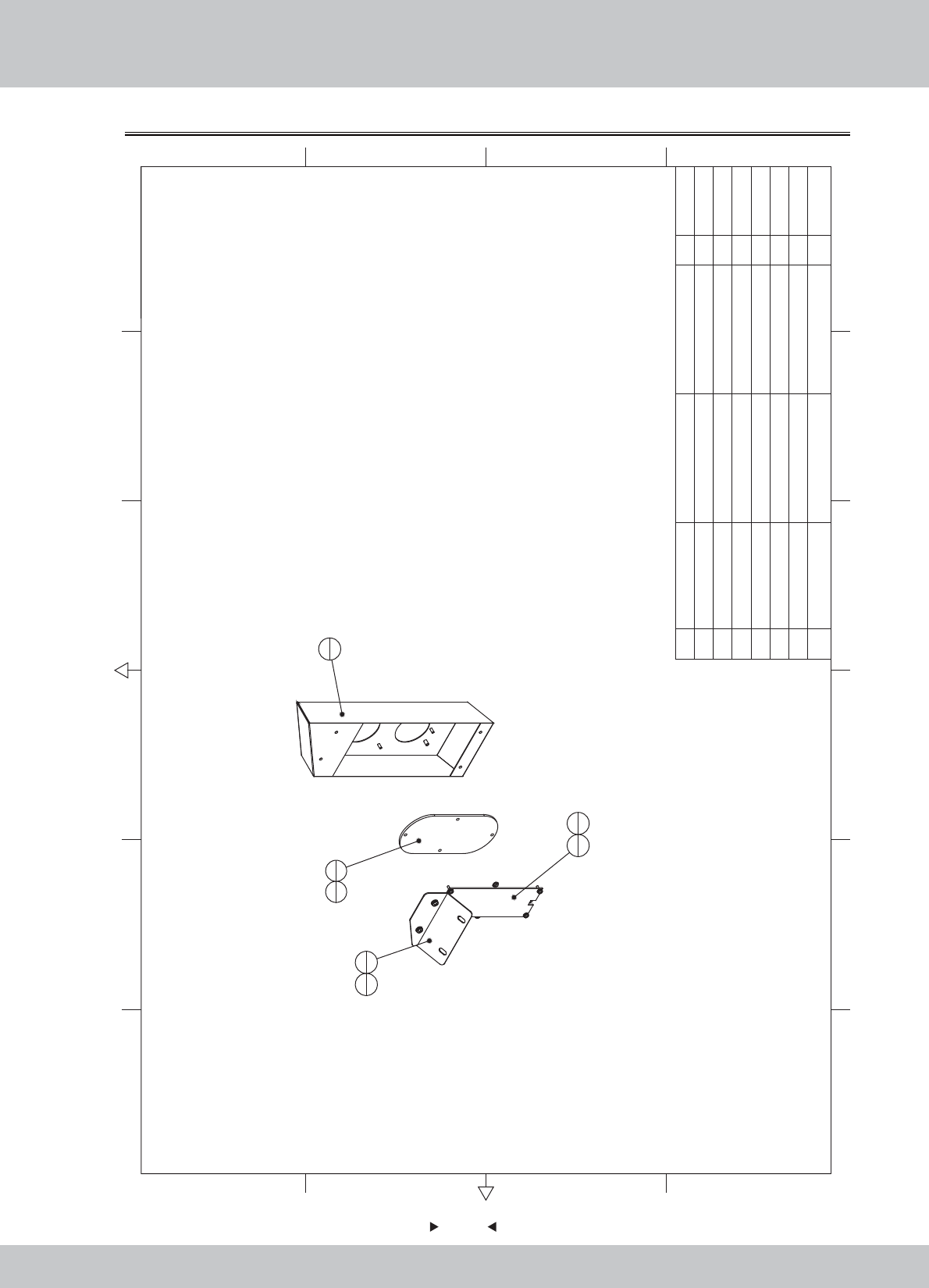
6.2 General assembly(1)
56
56
2
1
1
1
5
1
29
6
7
1
6
1
29
4
9
1
8
1
30
6
30
6
13
1
29
4
22
135
433
434
4
16
1
21
1
28
1
27
1
37
4
17
235
16 33
16 36
22
23 M4*30(Black) 10
22 Pedal ASSY 1
21 SRF-0000C02 The steering wheel decoration piece Blue ABS 1
20 SRF-0000C01 Block plastic Black ABS 1
19 SRF-0000B01 Back door U HDF-15.0T 1
18 SRF-0000A02
Plastic console fixed iron
1
17 SRF-0000A01 Fixed iron frame SPCC-1.5T 2
16 SRF-1600000 Steeling wheel ASSY 1
15 SRF-1500000
in
termediate ASSY of back door plate 1
14 SRF-1400000
Upper ASSY of back door
1
13 SRF-1300000 pedal ASSY 1
12 SRF-1200000 Stepping cover ASSY 1
11 SRF-1100000 Coin door ASSY 1
10 SRF-1000000 Push rod ASSY 1
9 SRF-0900000 Left side light ASSY 1
8 SRF-0800000 Right side light ASSY 1
7 SRF-0700000 Billbord ASSY 1
6 SRF-0600000 Pick-up head ASSY 1
5 SRF-0500000 LCD glass ASSY 1
4 SRF-0400000 LCD ASSY 1
3 SRF-0300000 Plastic console ASSY 1
2SRF-0200000 Seat ASSY 1
1SRF-0100000 General ASSY 1
1.6.LS243011
SD2
2.1.IG040420
1.1.WA10E00010
1.1.WA10E00020
1.2.WA10E00010
1.8.WA10E010
1.8.WA10E020
12 6
43 5
365
421
A
B
C
D
C
D
B
A
No. Draw No. Name Material/Spec.
Product Code
Qty.
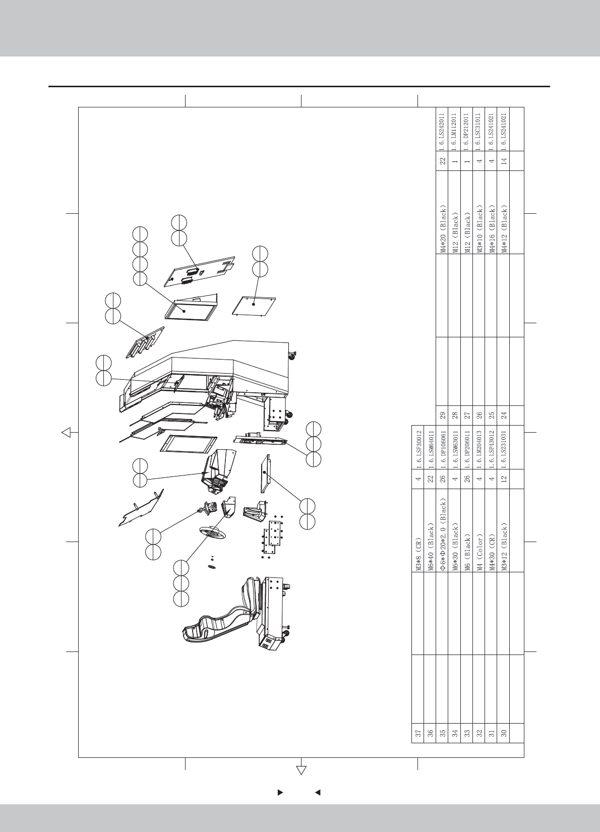
General assembly(2)
57
57
12 6
43 5
365
421
A
B
C
D
C
D
B
A
4
135
633
636
22
10
1
25
4
11
131
432
4
12
1
29
4
14
1
15
1
19
1
23
4
23
4
20
1
26
4
24
4
18
129
4
3
124
10
23
2
No. Draw No. Name Material/Spec.
Product Code
Qty. No. Draw No. Name Material/Spec.
Product Code
Qty.
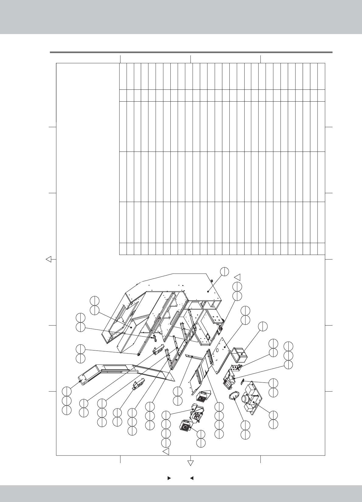
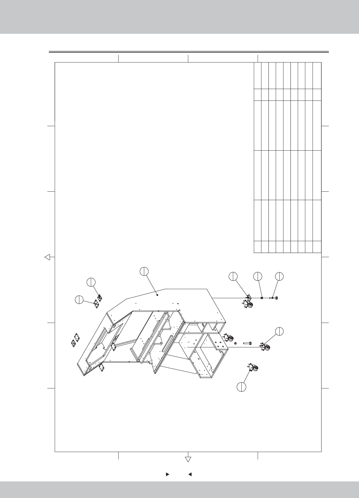
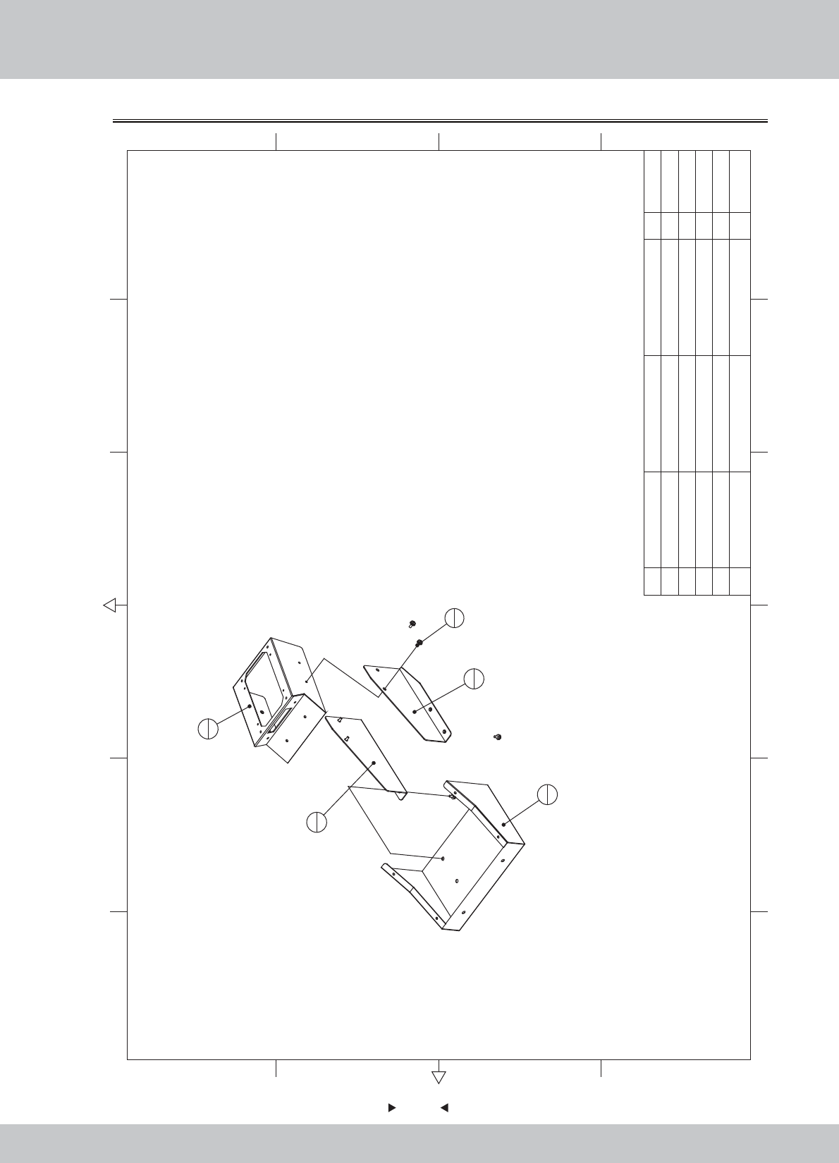
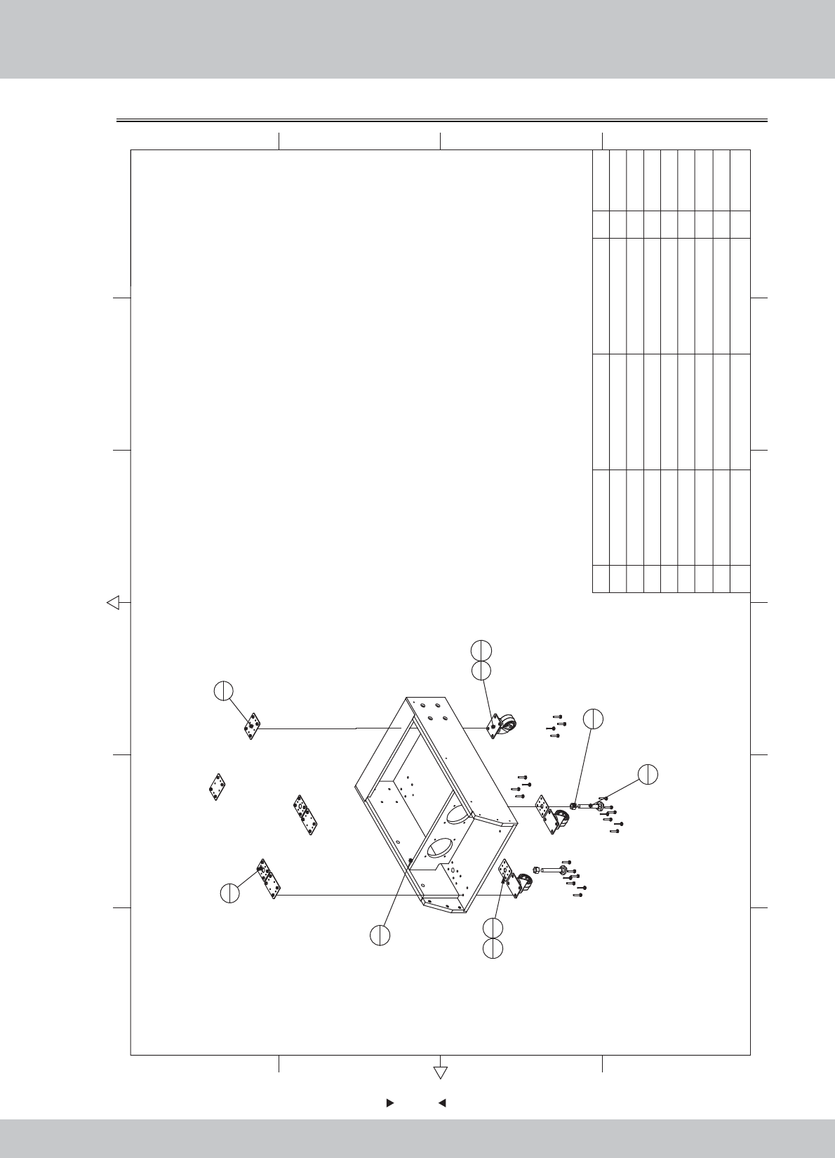
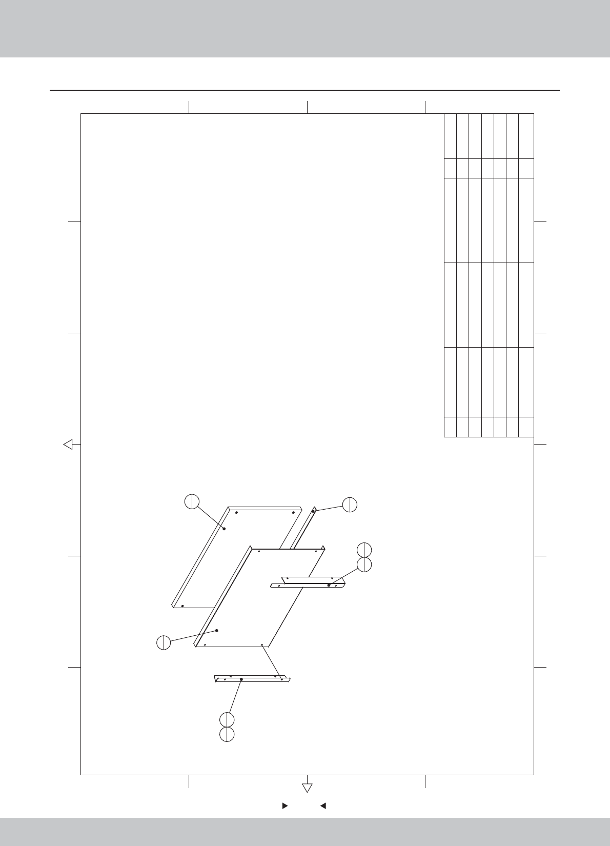
58
58
6.2.1 Main wooden frame assembly (1)
1.1.WA10E00140
1.1.WA10E00130
1.1.WA10E00120
1.1.WA10E00110
1.1.WA10E00100
1.1.WA10E00090
1.1.WA10E00080
1.1.WA10E00070
1.1.WA10E00060
1.1.WA10E00050
1.1.WA10E00040
1.1.WA10E00030
1.1.WA10E00660
12 6
43 5
365
421
A
B
C
D
C
D
B
A
18
2
19
2
42
6
36
4
42
6
36
4
20
139
2
21
138
4
22
1
37
4
24
1
43
4
44
2
49
1
26
137
6
30
1
41
2
1
25
152
42
27 sr1-0000a03 Speaker fixed iron SPCC-1.5 2
26 SRF-0100D01 Light Box Acrylic PMMA-3.0T 1
25 SRF-0100A15 Coin plate SPCC-1.5T 1
24 SRF-0100A14 Console cover under 1
23 SRF-0100A13 Camera light barrier SPCC-1.0T 1
22 SRF-0100A12 Bass Cover SPCC-1.2T 1
21 SRF-0100A11 Pedal under cover SPCC-1.2T 1
20 SRF-0100A10
Plastic edge fixed iron
SPCC-1.2T 1
19 SRF-0100A09 Strengthening iron console L SPCC-2.0T 2
18 SRF-0100A08 Strengthening iron console R SPCC-2.0T 2
17 SRF-0100A07 Console fixed iron 1
16 SRF-0100A06 Fixed glass transom SPCC-1.2T 1
15 SRF-0100A05
Transformers planks fixed iron
SPCC-1.5T 1
14 SRF-0100A04 Monitor fixed iron under SPCC-2.0T 2
13 SRF-0100A03 Frame Iron L SPCC-1.2T 1
12 SRF-0100A02 Frame Iron R SPCC-1.2T 1
11
SRF-0100A01 Corner iron
SPCC-1.2T 1
10 SRF-0110000 PCB Board ASSY 1
9
SRF-0109000 Plastic step box ASSY
1
8 SRF-0108000 LEFT small light ASSy 1
7
SRF-0107000 RIGHT small light ASSY
1
6 SRF-0106000 Service board assembly 2
5 SRF-0105000 Service board ASSY 1
4
SRF-0104000 Transformer board ASSY
1
3
SRF-0103000 Power box ASSY
1
2
SRF-0102000 Main frame ASSY
1
1
SRF-0101000 Main wooden frame Assy
1
1.2.WA10E00020
1.1.WA10A00030
1.7.WA10E00010
1.1.WA10E00160
1.1.WA10E00160
2
1
47
6
46
6
48
6
1
1
4
1
43
25
137
4
6
2
39
8
8
1
7
1
37
4
37
4
9
137
245
8
11
1
38
2
13
1
36
8
15
1
39
2
16
1
39
4
17
1
39
4
33
8
No. Draw No. Name Material/Spec.
Product Code
Qty.
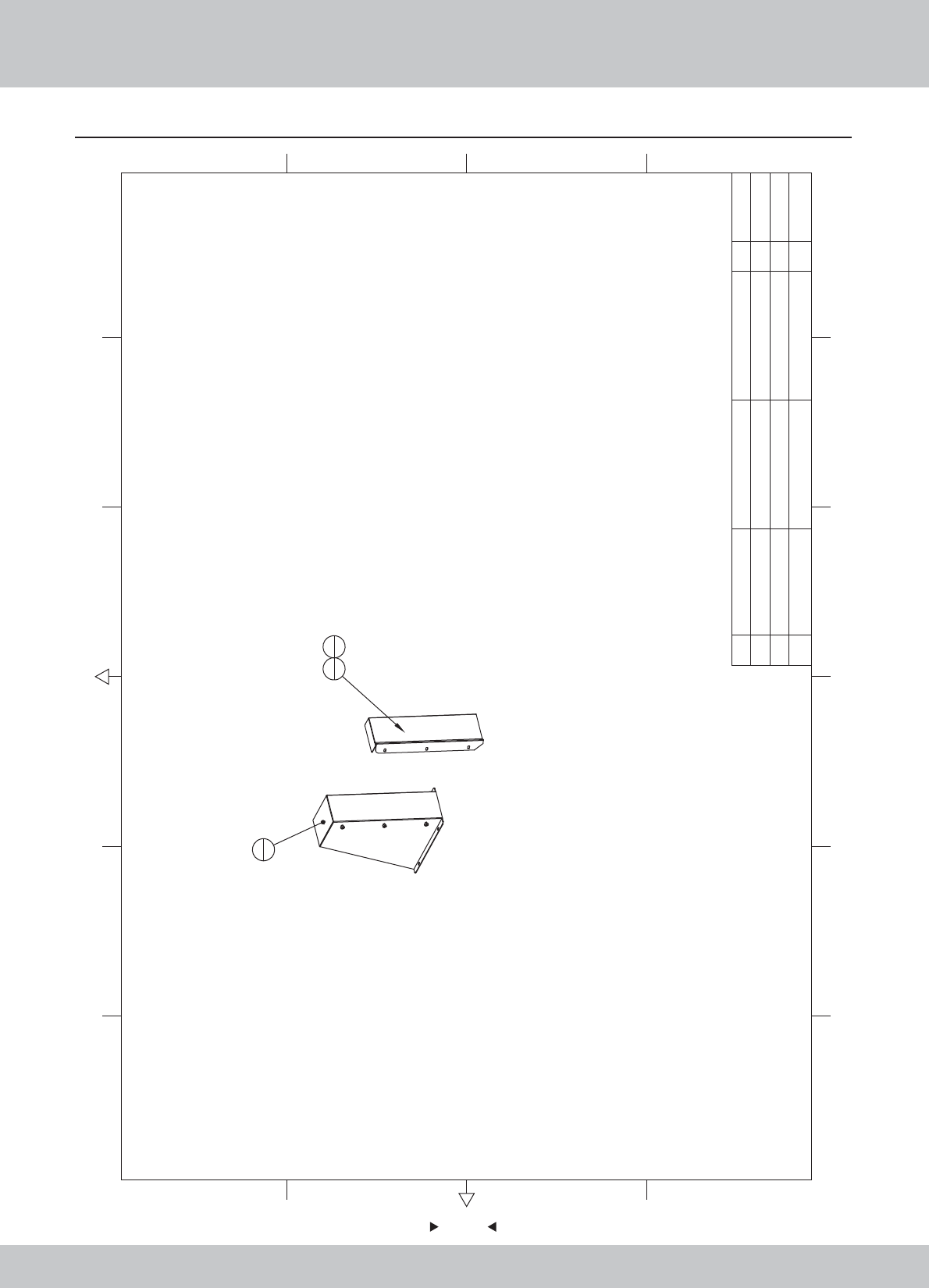
59
59
Main wooden frame assembly(2)
12 6
43 5
365
421
A
B
C
D
C
D
B
A
3
137
3
12
136
8
14
2
40
4
23
1
38
427
229
239
4
32
131
235
434
4
10
1
28
1
41
2
50
451
4
No. Draw No. Name Material/Spec.
Product Code
Qty.
60
60
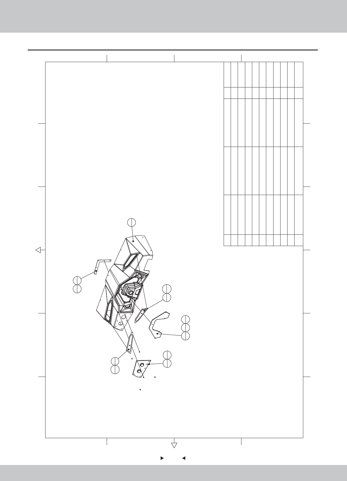
6.2.2 Main frame assembly
1
1
4
2
5
46
2
7
2
3
4
2
2
8
24
8 M6*35 24
7M162
6 M16*Y100 2
52.54
4 WAH-0000A06 SPCC-2.0T 2
3 WAH-0000A05 SPCC-2.0T 4
2 WAH-0000A04 SPCC-2.0T 2
1 SRF-0101B01 HDF 1
12 6
43 5
365
421
A
B
C
D
C
D
B
A
No. Draw No. Name Material/Spec.
Product Code
Qty.
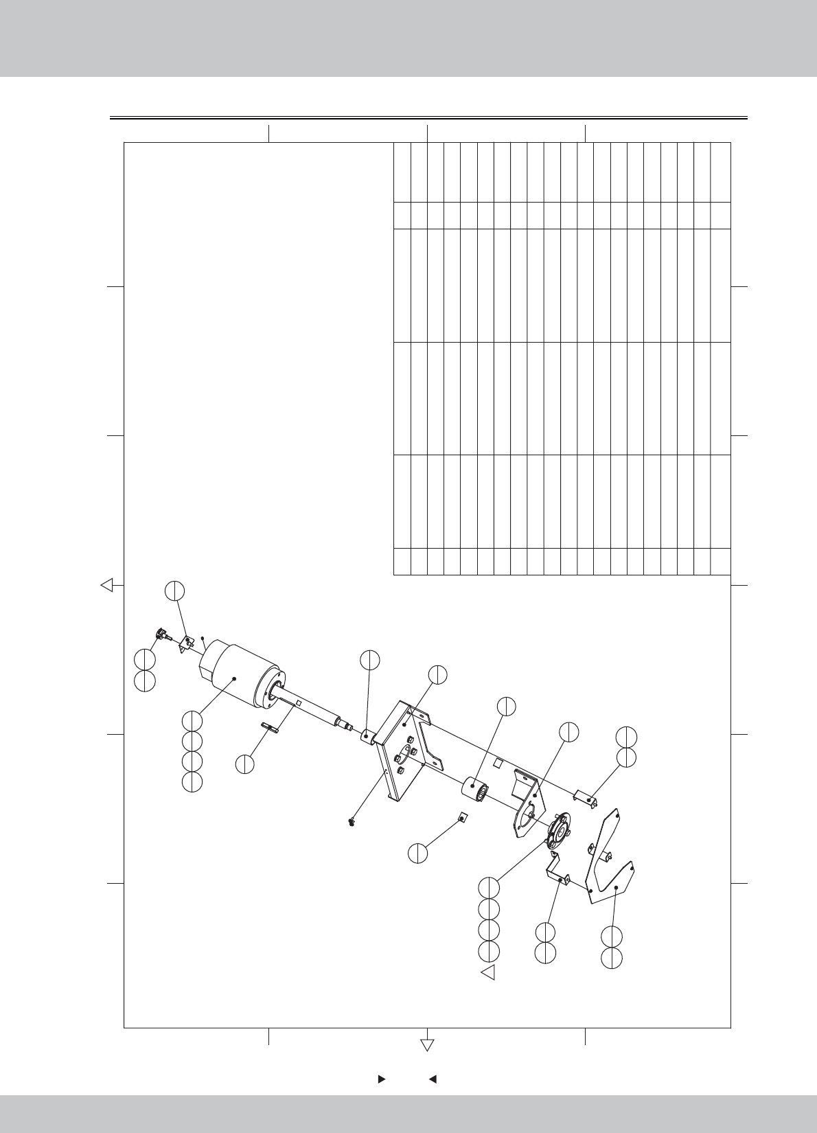
61
61
6.2.3 Motor assembly
1
1
2
1
7
1
5
1
6
1
8
2
9
1
11
1
12
1
13
1
16
4
17
4
18
4
16
3
17
3
18
3
19
1
3
2
4
1
15
2
15
2
10
1
14
3
1
19 M5*6(Black) 1
18 M8*20(Black) 7
17 M8(Black) 7
16 φ8*φ16*2.0(Black) 7
15 M4*8(Black) 4
14 M3*8(Black) 3
13 Bearing PF205 1
12 Potentiometer B-5KΩ 270 1
11 DC motor 112ZY100-40 1
10 Meter PCB WL_PCBO_0001_0010 1
9 SR1-0501A07 VR fixing plate SPCC-1.0 1
8 SR1-0501A05 Swing axle pad 2
7 SR1-0501A04 Swing motor shaft 45 1
6 SR1-0501A03 Shaft key 45 1
5 SR1-0501A02 Motor bushings 45 1
4 SRF-0102A04
Panel lights fixed iron B
SPCC-1.2T 1
3 SRF-0102A03
Panel lights fixed iron A
SPCC-1.2T 2
2 SRF-0102A02 Motor fixed plate SPCC-3.0T 1
1 SRF-0102A01
Iron shaft support Front
SPCC-3.0T 1
1.1.WA10E00170
1.1.WA10E00180
1.1.WA10E00190
1.1.WA10E00200
1.1.WA10A00230
1.1.WA10A00240
1.1.WA10A00250
1.1.WA10A00260
1.1.WA10A00280
1.4.IC901780
1.4.MD100022
1.4.VR150220#
1.4.ZC001010
1.6.LS830021
1.6.LS840021
1.6.DP108031
1.6.DP208011
1.6.LSM82011
1.6.LST50011
12 6
43 5
365
421
A
B
C
D
C
D
B
A
No. Draw No. Name Material/Spec. Product CodeQty.
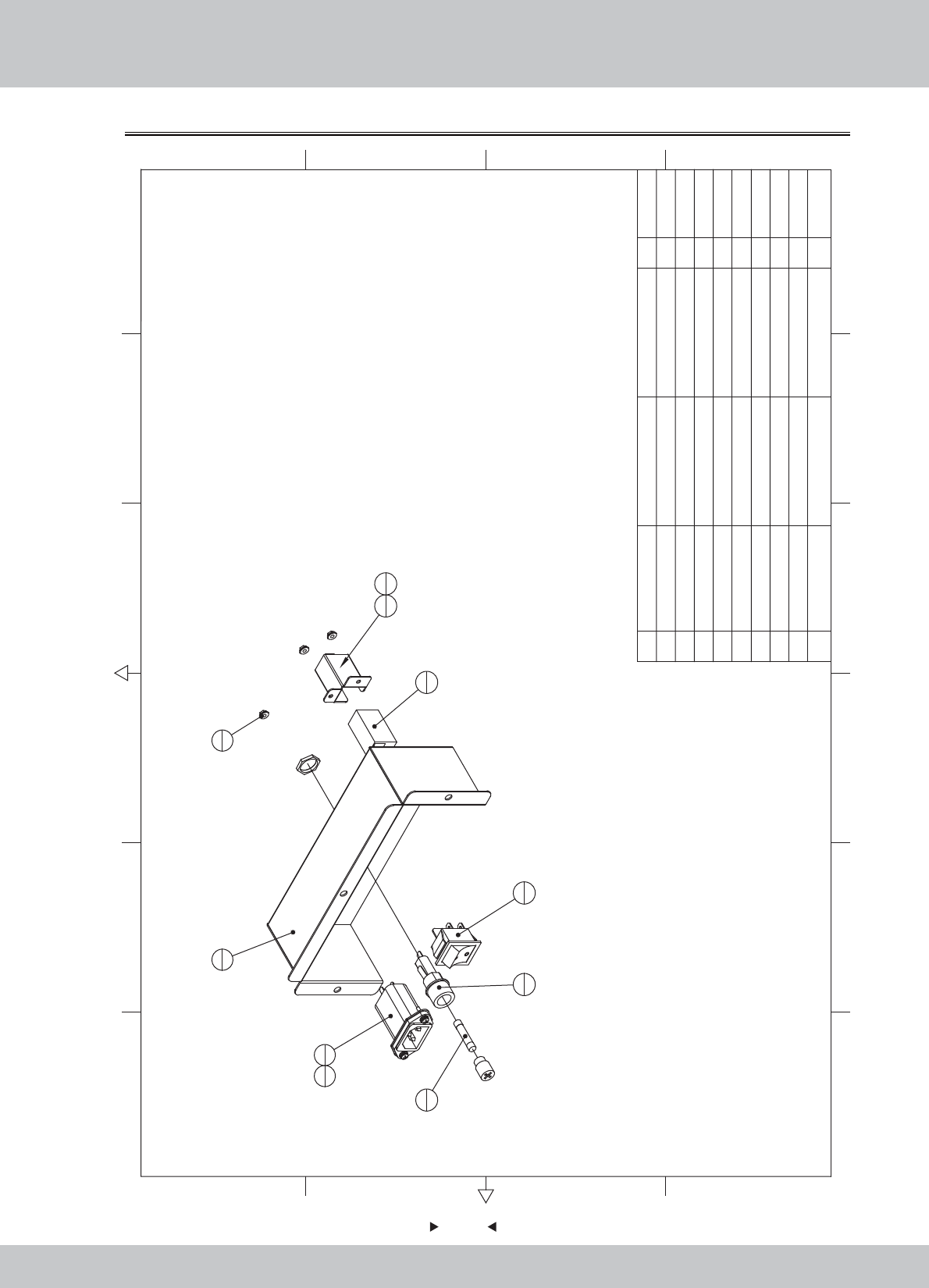
62
62
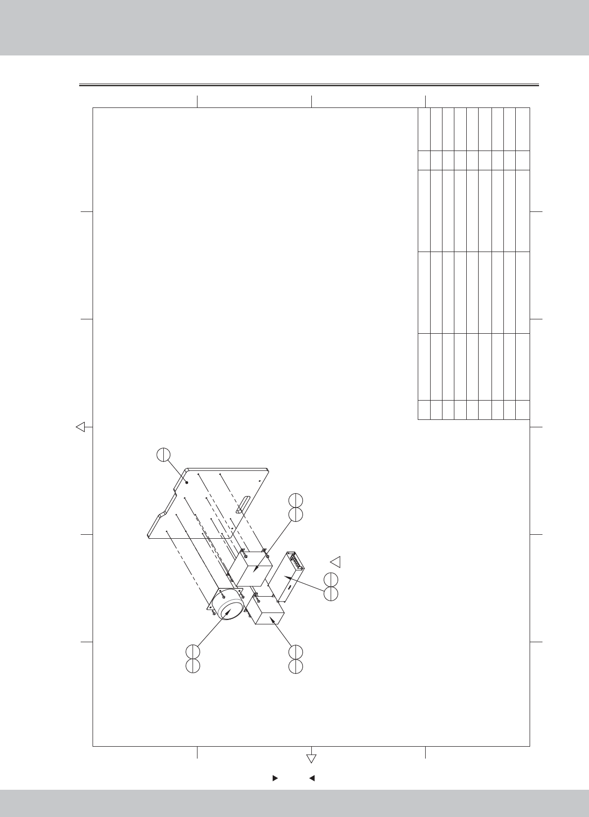
6.2.4 Power box assembly
1
1
4
1
3
1
6
1
5
1
7
1
2
19
2
9
1
8
2
9M3(Color) 3
8M3*12(Black) 2
7 twork Adapter 1
6Fuse tube F6A/6*30 250V 1
5
Rocker Switch
4P KCD7-2211N 1
4
Filter
15GEEG3E 10A/250V 1
3
Fuse tube
F15A/125V 1
2 SRC-0401UK Rail Network port fixed iron SPCC-1.0 1
1 SRF-0103A01 Power Fixed Box SPCC-1.2T 1
1.1.WA10E00210
1.1.SE11A00170
1.4.BX300020
1.4.LB100020
1.4.SW604010
1.4.BX106010
1.5.XC201030
1.6.LS831021
1.6.LM203013
12 6
43 5
365
421
A
B
C
D
C
D
B
A
No. Draw No. Name Material/Spec.
Product Code
Qty.
63
63
6.2.5 Transformer board assembl
12 6
43 5
365
421
A
B
C
D
C
D
B
A
1
1
3
1
5
1
6
4
7
2
4
1
6
4
1
2
18
4
8M5*16(Black) 4
7M3*12(Cr) 2
6M4*16(Black) 8
5 Power supply RS-150-12 1
4 Transformer 350W 110V/110V-14V 1
3Toroidal transformer
220V/110V转16-0-16V 250W
1
2Transformer HL1100W 220V/110V 1
1 SRF-0104B01
Transformer fixed plate
MDF-15.0T 1
1.2.WA10E00030
1.4.BY111010
1.4.BY307010
1.4.BY203040
1.4.DY06A010
1.6.LS841031
1.6.LS331022
1.6.LS851021
No. Draw No. Name Material/Spec.
Product Code
Qty.
64
64
6.2.6 Service board assembly
1
1
4
3
5
3
3
4
2
1
5Potentiometer kNo.b Ф13mm 3
4 Volume VR VR-B10KΩ 3
3 Button SDP-103C-22RB 4
2 Counter DC 5V 1
1 SRF-0105A01 Service key plate SPCC-1.2T 1
1.1.WA10E00220
1.4.JS100020
1.4.AJ500012#
1.4.VR160010
1.4.VR201310
12 6
43 5
365
421
A
B
C
D
C
D
B
A
No. Draw No. Name Material/Spec. Product CodeQty.
65
65
6.2.7 Speaker assembly
1
1
2
2
3
1
4
1
6
4
7
4
5
4
7M4*12(Black) 4
6M4*12(Black) 4
5M4*8(Black) 4
4Speaker(round)
4吋 4Ω/25W
1
3 SR1-0503B01 Speaker boxes MDF-9.0T 1
2 SR1-0503A01
Speaker boxes fixed iron
SPCC-1.2 2
1 SRF-0106A01
Speaker seat fixed iron
SPCC-1.2T 1
1.1.WA10E00230
1.1.WA10A00310
1.2.WA10A00030
1.4.YS204031
1.6.LS840021
1.6.LS341021
1.6.LS841021
12 6
43 5
365
421
A
B
C
D
C
D
B
A
No. Draw No. Name Material/Spec.
Product Code
Qty.
66
66
6.2.8 Right small light assembly
1
1
3
1
4
1
2
1
5
4
6
4
7
2
7M4*8(Black) 2
6M3*8(Black) 4
5M3(Color) 4
4
Lightbox PCB
WL_PCBO_0001_0009 1
3 SR1-0701D01 LED light box cover 1
2 SRF-0107A02 Light boxes fixed iron R SPCC-1.2T 1
1 SRF-0107A01 Light box R SPCC-1.0T 1 1.1.WA10E00240
1.1.WA10E00250
1.7.WA10A00420
1.4.IC901090
1.6.LM203013
1.6.LS830021
1.6.LS840021
12 6
43 5
365
421
A
B
C
D
C
D
B
A
No. Draw No. Name Material/Spec.
Product Code
Qty.
67
67
6.2.9 Left small light assembly
4
16
4
7
22
1
5
4
1
1
3
1
7M4*82
6M3*8
4
5M34
4Lightbox PCB WL_PCBO_0001_0009 1
3 SR1-0701D01 LED light box cover 1
2 SRF-0108A02 Light boxes fixed iron L SPCC-1.2T 1
1 SRF-0108A01 Light box L SPCC-1.0T 1 1.1.WA10E00260
1.1.WA10E00270
1.7.WA10A00420
1.4.IC901090
1.6.LS840021
1.6.LS830021
1.6.LM203013
12 6
43 5
365
421
A
B
C
D
C
D
B
A
No. Draw No. Name Material/Spec. Product CodeQty.
68
68
6.2.10 Plastic step box assembly
1
1
4
1
3
1
2
1
5
6
5M4*86
4 SRF-0109A04 Fixed gear iron L SPCC-1.5T 1
3 SRF-0109A03 Fixed gear iron R SPCC-1.5T 1
2 SRF-0109A02 Fixed gear iron UP SPCC-1.5T 1
1 SRF-0109A01 Fixed gear iron under SPCC-1.2T 1
1.1.WA10E00280
1.1.WA10E00290
1.1.WA10E00300
1.1.WA10E00310
12 6
43 5
365
421
A
B
C
D
C
D
B
A
No. Draw No. Name Material/Spec. Product CodeQty.
69
69
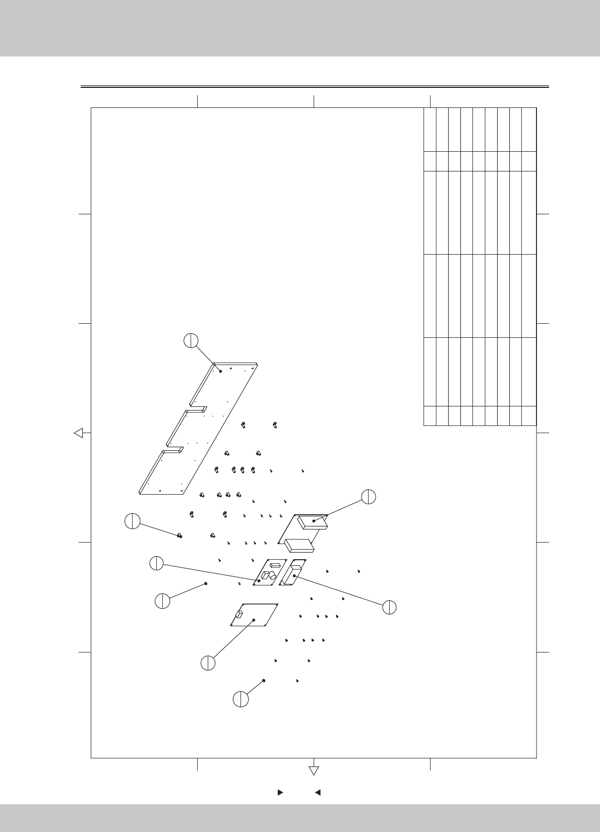
6.2.11 PCB board assembl
1
1
2
1
4
1
5
1
3
1
7
16
8
16
6
16
8M3*12(CR) 16
7M3*8(Black) 16
6L-holder M3mm 16
5
Vibration speaker driver board
GKP-VSB--2013-0503 1
4Amp board GKP-AMP6S-2013-0505 1
3Motion Board PCB GKP-Vibrator-2013-0502 1
2IO board PCB GKP-IO-2013-0501 1
1 SRF-0110B01 PCB fixing plate MDF-15.0T 1 1.2.WA10E00040
1.4.IC900022
1.4.IC901790
1.4.IC901810
1.4.IC901800
1.9.LX103010
1.6.LS830021
1.6.LS331022
12 6
43 5
365
421
A
B
C
D
C
D
B
A
No. Draw No. Name Material/Spec.
Product Code
Qty.
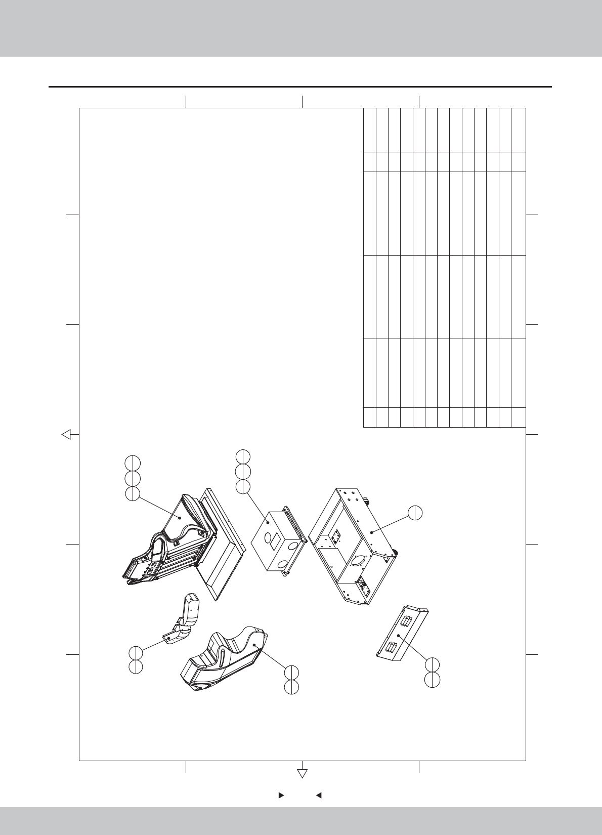
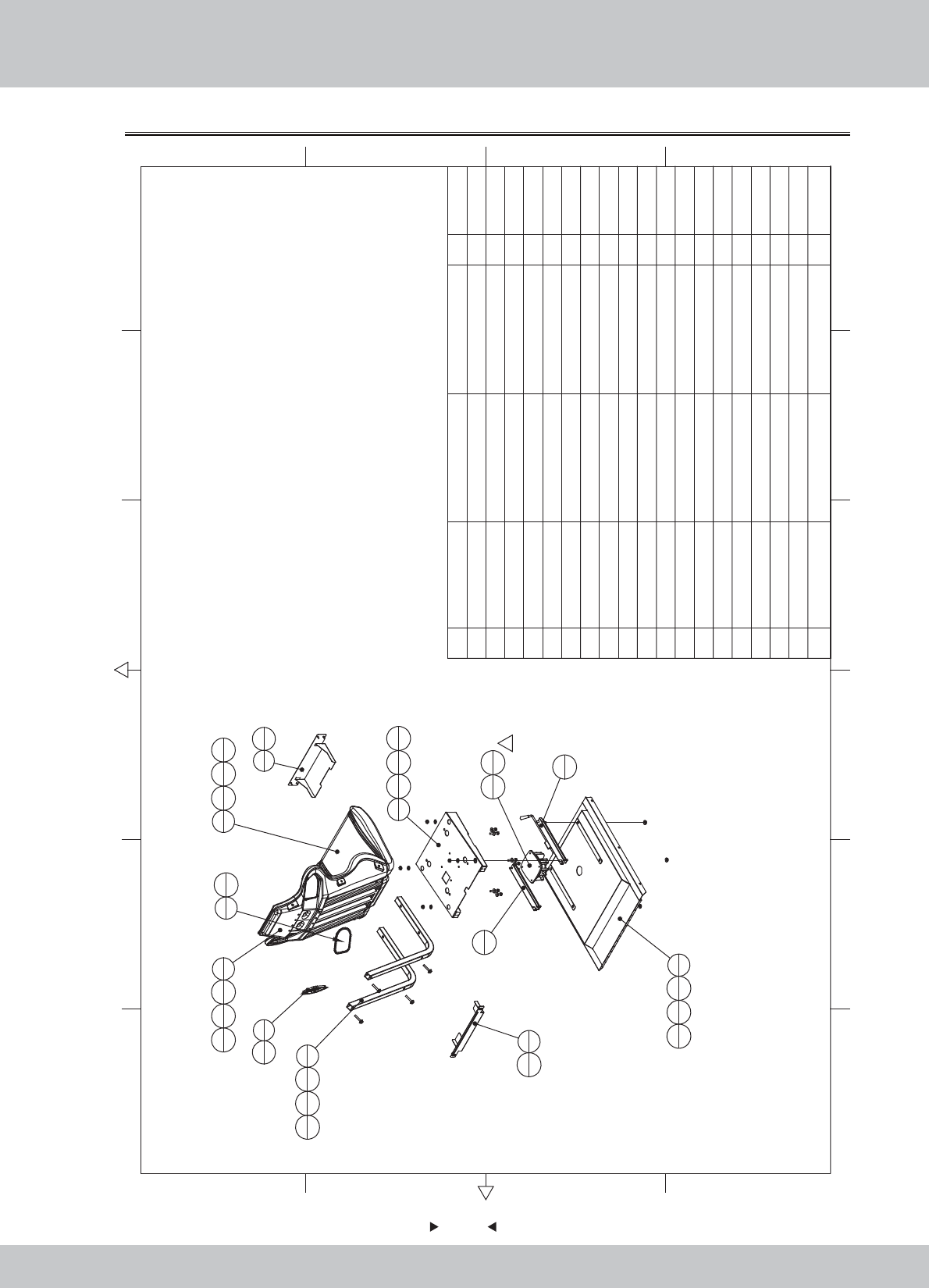
6.3 Seat assembly
70
70
5
421
A
B
C
D
C
D
B
A
1
1
2
111
612
4
3
1
10
4
9
4
4
2
7
8
5
1
11
6
6
1
8
6
12 M4*8(Black) 4
11 M4*20(Black) 12
10 M6(Color) 4
9M6*14/M6*25 4
8 6
7M4*12(Black) 8
6 The seat back cover ABS-3 1
5 SRF-0200A01 Rear-seat vents SPCC-1.2T 1
4 SRF-0204000 Backest 2
3 SRF-0203000 Mainframe ASSY 1
2 SRF-0202000
Upper ASSY
1
1 SRF-0201000
Seat frame Assy
11.2.WA10E00050
1.1.WA10E00320
1.8.WA10A020
1.6.LS841021
1.6.LSY82050
1.6.LSW61020
1.6.LM206013
1.6.LS242011
1.6.LS240021
12 6
43 5
36
No. Draw No. Name Material/Spec.
Product Code
Qty.
71
71
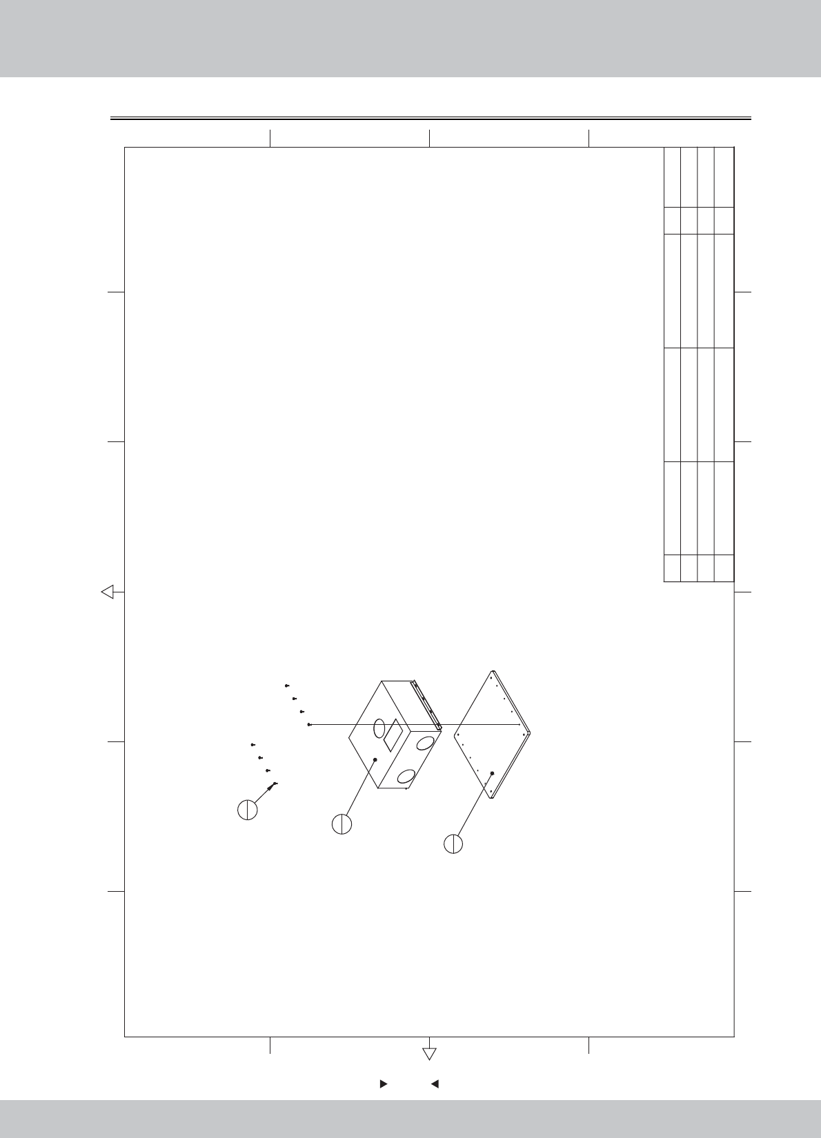
6.3.1 Seat wooden crate assembly
12 6
43 5
365
421
A
B
C
D
C
D
B
A
1
1
4
2
5
4
6
2
7
2
8
8
8
16
3
4
2
2
8M6*35 24
7M16 2
6M16*Y100
2.5
2
54
4 WAH-0000A06 SPCC-2.0T 2
3 WAH-0000A05 SPCC-2.0T 4
2 WAH-0000A04 SPCC-2.0T 2
1 SRF-0201B01
Seat frame
11.2.WA10E00050
1.2.WA10E00050
1.2.WA10E00050
1.2.WA10E00050
1.2.WA10E00050
1.2.WA10E00050
1.2.WA10E00050
1.2.WA10E00050
No. Draw No. Name Material/Spec.
Product Code
Qty.
72
72
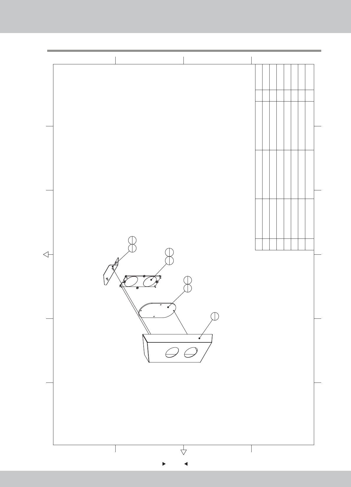
6.3.2 Upper assembly of seat
12 6
43 5
365
421
A
B
C
D
C
D
B
A
5
1
1
1
13
4
14
4
15
4
2
113
414
417
4
3
1
17
4
14
4
13
4
11
1
10
1
4
115
414
413
4
6
1
18
4
18
4
7
2
13
4
14
4
16
4
8
1
19
5
9
119
5
12
118
41
19 M4*8(CR) 10
18 M4*12(Black) 12
17 M8*50(Black) 8
16 M8*20(Black) 4
15 M8(Color) 8
14 M8(Black) 20
13 φ8*φ22*2.0(Black) 20
12
Low-frequency vibrators
4Ω/50W 1
11 Track R 1
10 Track L 1
9 Seat speaker cover R SD2 1
8 Seat speaker cover L SD2 1
7 SD3-07-01-01 Seat elbow 30×2/Q235 2
6 1170
Seat frame iron block front
SPCC-1.0 1
5 1160
Seat frame iron block after
SPCC-1.0 1
4 1150-C Seat frame 1
3 SRF-0202C02 seat back cushion Blue ABS 1
2 SRF-0202C01 The seat cushion Blue ABS 1
1 SRF-0202A01 Seat base cover SPCC 1
1.1.WA10E00330
1.8.WA10E030
1.8.WA10E040
1.1.IG040170
1.1.IG040180
1.1.IG040190
1.1.IG04A00650
1.1.IG041000
1.1.IG041001
1.1.AA030100
1.1.AA030101
1.4.YSA00010
1.6.DP108031
1.6.DP208011
1.6.LM208013
1.6.LSM82011
1.6.LSM85011
1.6.LS841021
1.6.LS340012
No. Draw No. Name Material/Spec.
Product Code
Qty.
73
73
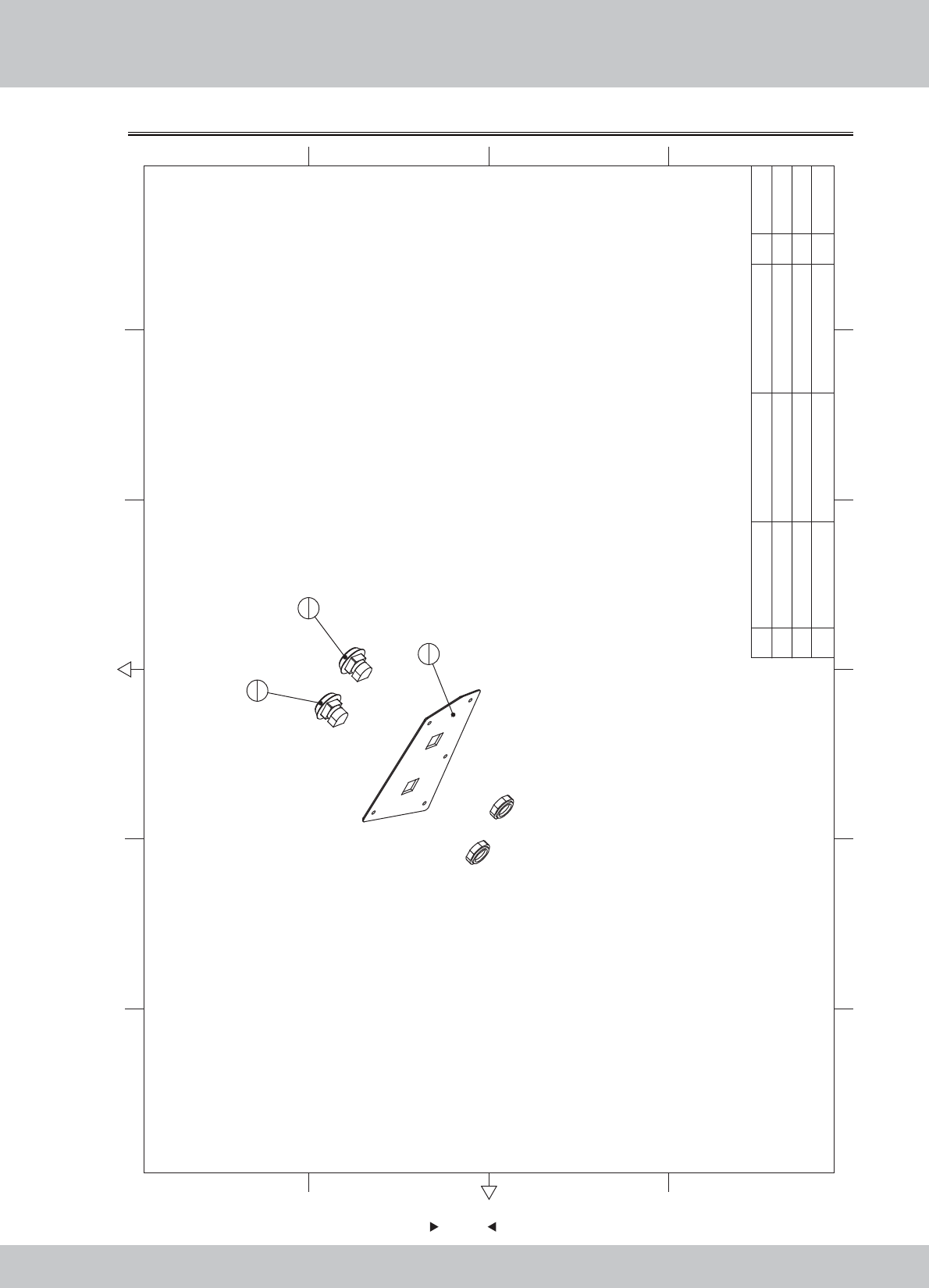
6.3.3 Mainframe assembly
1
1
2
1
3
8
3M4*12(Black) 8
2
Computer Advantech IPC-WL001-G860
1
1 SRF-0203B01
Host fixed plate
HDF-12.0T 1
1.2.WA10E00060
1.4.ZJ010026
1.6.LS841021
12 6
43 5
365
421
A
B
C
D
C
D
B
A
No. Draw No. Name Material/Spec. Product CodeQty.
74
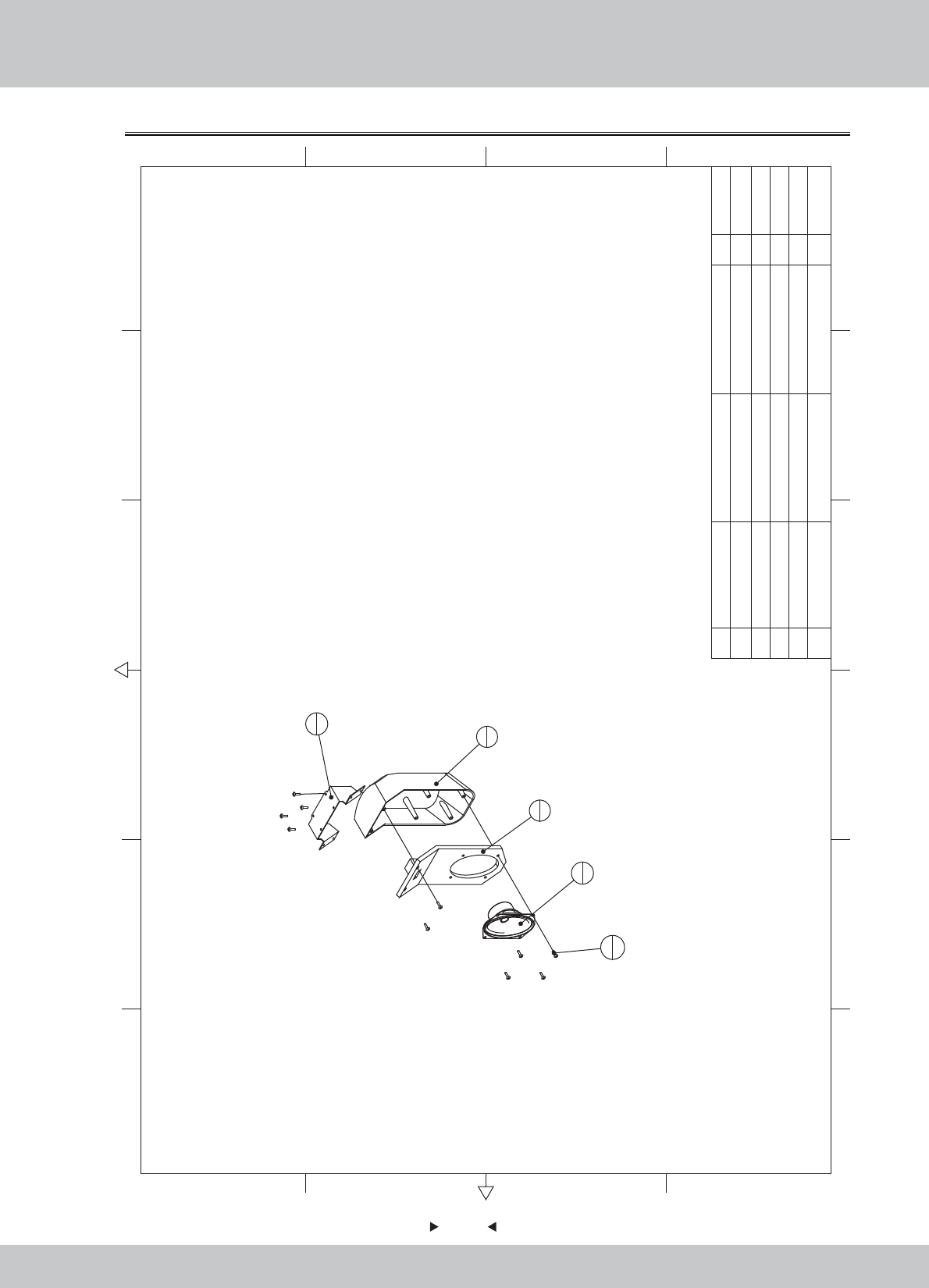
74
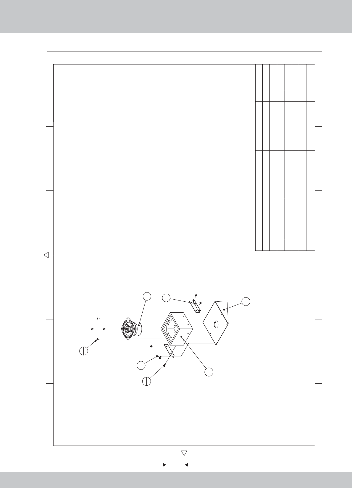
6.3.4 Backrest horn assembly
4
1
3
1
2
1
1
1
5
10
5M4*16(Black) 10
4Speaker(Oval)
3*5吋 8Ω/15W
1
3Seat horn hood SD2 1
2Seat horn cap SD2 1
1 6100 Backrest speaker fixed iron SPCC-1.5 1 1.1.IG040700
1.8.IG040330
1.8.IG040320
1.4.YS300010
1.6.LS341041
12 6
43 5
365
421
A
B
C
D
C
D
B
A
No. Draw No. Name Material/Spec.
Product Code
Qty.
75
75
6.4 Plastic console assembly
SPCC-1.2T 1
5 SRF-0300D01 Meter Acrylic PMMA-5.0T 1
4 SRF-0300C01 Control panel plastic Black ABS 1
3 SRF-0300A03 Key fixed iron SPCC-1.5T 1
2 SRF-0300A01
Console speaker cover L
SPCC-1.2T 1
1 SRF-0301000 Console keyboard ASSY 1
1.1.WA10E00340
1.1.WA10E00360
1.8.WA10E050
1.7.WA10E00070
1.1.WA10E00350
1.6.LS241021
1.6.LM204013
1.6.LSC41021
1.6.LM203013
12 6
43 5
365
421
A
B
C
D
C
D
B
A
2
1
6
1
3
1
4
1
5
1
10
3
10
3
9
2
7
58
5
1
17
3
10 M3(Color) 6
9M4*12(BLack) 2
8M4(Color) 5
7M4*12(Black) 8
6 SRF-0300A02
Console speaker cover R
No. Draw No. Name Material/Spec. Product CodeQty.
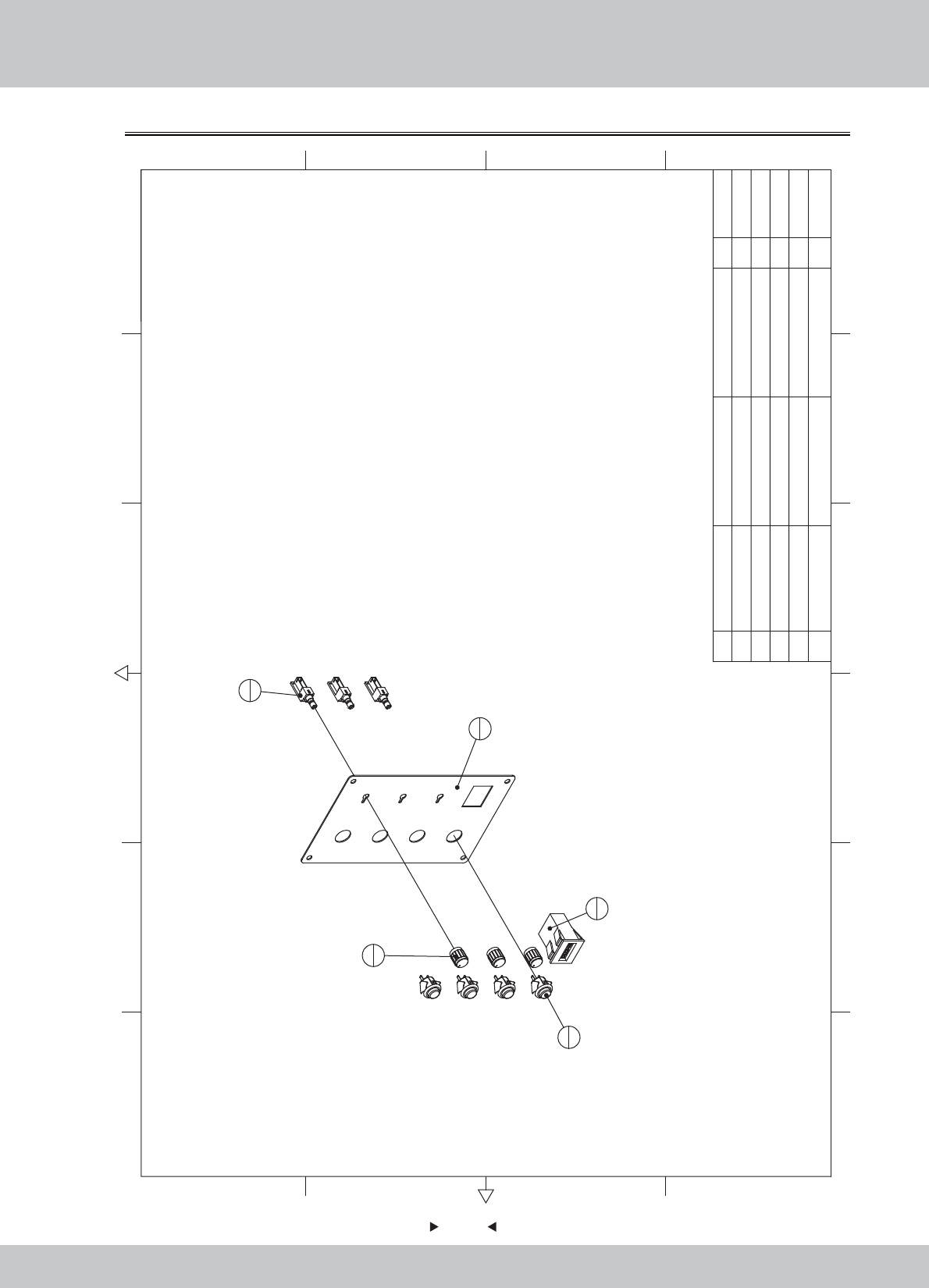
76
76
6.4.1 Console keyboard assembly
2
1
3
1
1
1
3
Button(Attached lights BLUE)
WLP-002 1
2
Button(Attached lights RED)
WLP-001 1
1
Key board Acrylic
PMMA-3.0T 1
1.7.WA10F00060
SRF-P0004E
1.4.AJ130012#
1.4.AJ130013#
12 6
43 5
365
421
A
B
C
D
C
D
B
A
No. Draw No. Name Material/Spec. Product CodeQty.
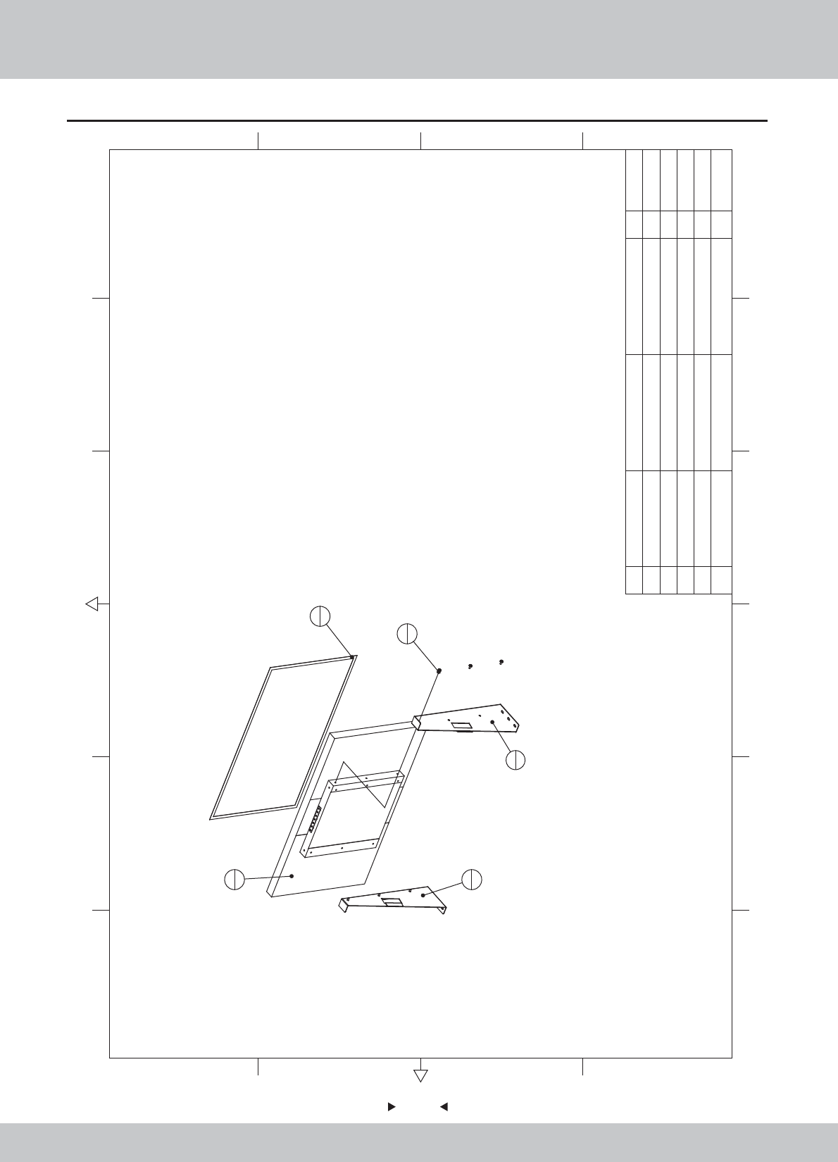
6.5 LCD assembly
77
77
4
1
3
1
2
1
1
1
5
6
5M6*12(Black) 6
43M1
3 SRF-0400A02 SPCC-2.5T 1
2 SRF-0400A01 LCD bracket L SPCC-2.5T 1
1Monitor 1
37"LED 1
.4.XS403740
1.1.WA10E00370
1.1.WA10E00380
1.9.JZ060010
1.6.LS861021
LCD bracket R
12 6
43 5
365
421
A
B
C
D
C
D
B
A
No. Draw No. Name Material/Spec. Product CodeQty.
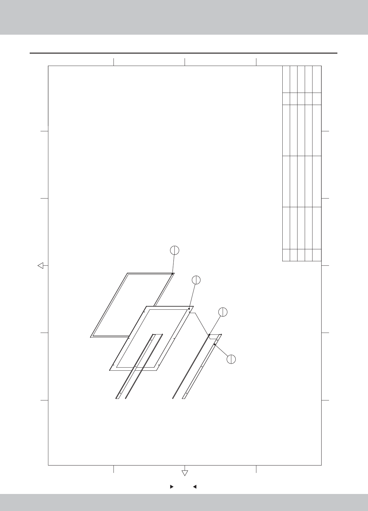
6.6 LCD glass assembly
78
78
3
1
1
1
2
2
4
2
4 EVA 3*20mm 10 2
3 EVA 3*20mm 10 1
2 SRF-0500A01 Pressed glass iron SPCC-1.2T 2
1 SR1-0600C01
Led glass
908*575.5*5 1 1.8.WA10A100
1.1.WA10E00390
1.9.HM020030
1.9.HM020030
12 6
43 5
365
421
A
B
C
D
C
D
B
A
No. Draw No. Name Material/Spec.
Product Code
Qty.
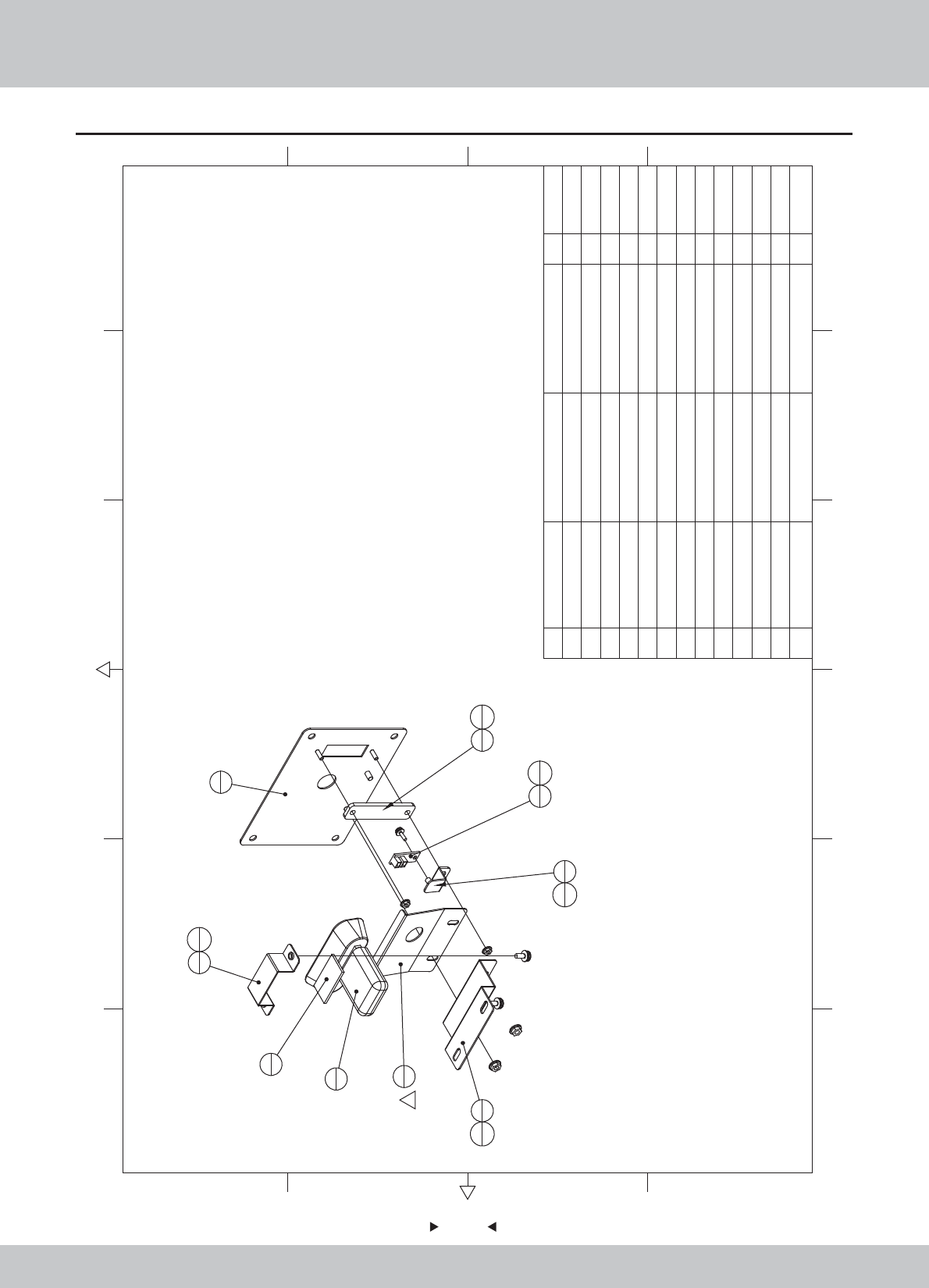
6.7 Pick-up head assembly
79
79
4 SRF-0600A04 Flash light fixed iron SPCC-1.2T 1
3 SRF-0600A03 Camera cover plate SPCC-1.0T 1
2 SRF-0600A02 Camera adjustment iron SPCC-1.2T 1
1 SRF-0600A01 Camera mounts SPCC-1.2T 1
1.1.WA10E00400
1.1.WA10E00410
1.1.WA10E00420
1.1.WA10E00430
1.1.WA10E00650
1.7.WA10E00020
1.4.SX010020
1.4.IC901540
1.9.HM020030
1.6.LS830021
1.6.LS840021
1.6.LM204013
1.6.LM203013
12 6
43 5
365
421
A
B
C
D
C
D
B
A
1
1
6
1
4
1
8
1
13
1
13
1
2
1
12
2
3
111
2
7
1
10
1
9
1
5
1
1
13 M3(Color) 2
12 M4(Color) 2
11 M4*8(Black) 2
10 M3*8(Black) 1
9 EVA 3*20mm 10 1
8 Camera light PCB Blue, 20mm 1
7 Camera Logitech C270 1
6 SRF-0600D01 Flash light Acrylic 雾白PMMA-3.0T 1
5 SRF-0600A05 Camera angle iron SPCC-1.0T 1
No. Draw No. Name Material/Spec.
Product Code
Qty.
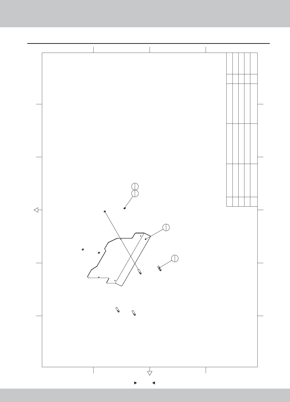
6.8 Billboard Assembly
80
80
4M4*12(CR) 4
3sd3-08-00-04
Billboards fixed block
S45C 4
2 sr1-0700a02
Arylic support shaft
45 4
1 SRF-0700D01 Billboards Acrylic PMMA-5.0T 1
1.7.WA10F00030
1.1.WA10A00350
1.1.IG04A00840
1.6.LSF41022
12 6
43 5
365
421
A
B
C
D
C
D
B
A
1
1
2
4
3
44
4
No. Draw No. Name Material/Spec. Product CodeQty.
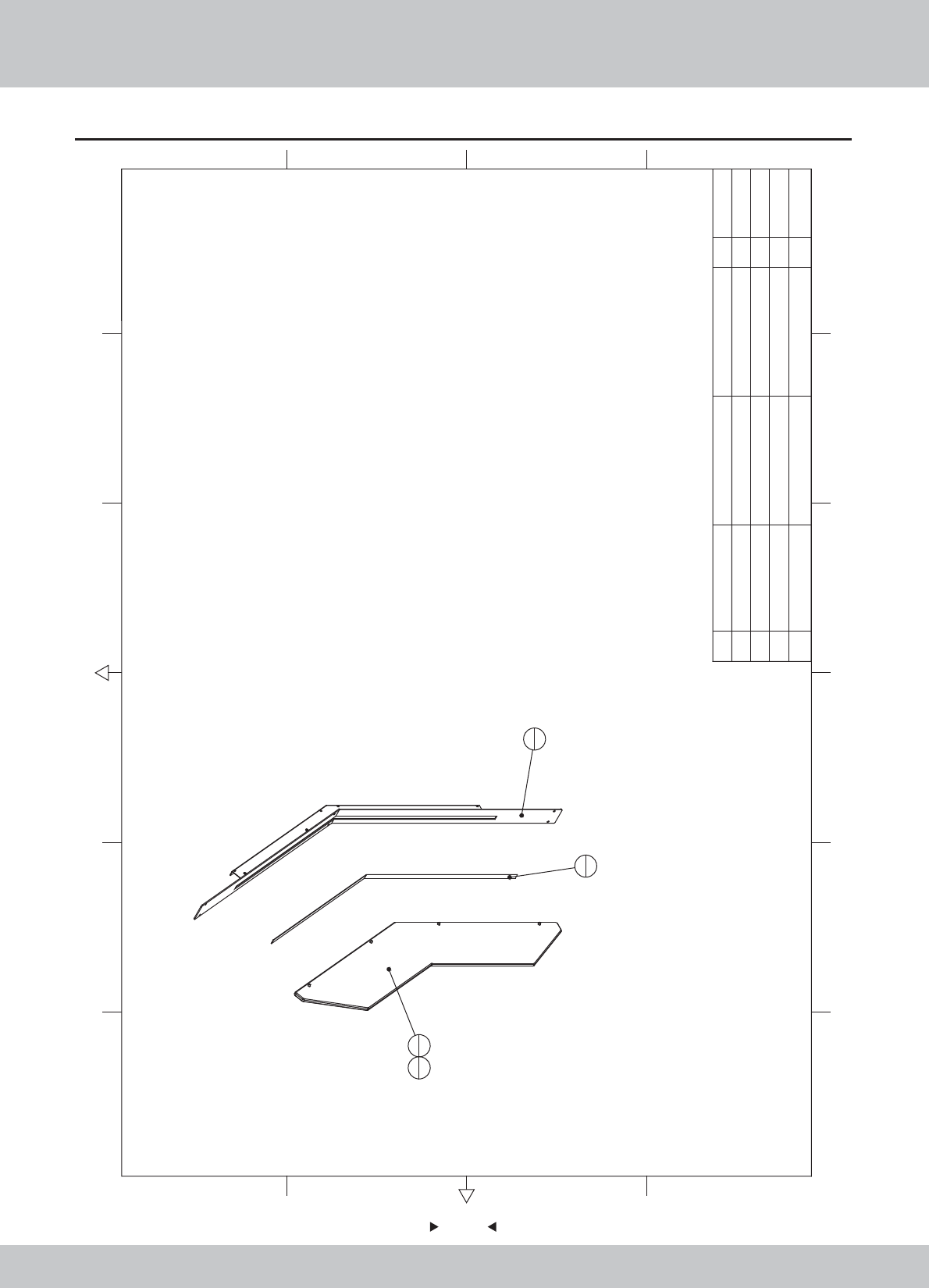
6.9 Right side light assembly
81
81
2
1
3
1
1
1
4
4
4M4*12(Black) 4
3Flexible Strip Light 5050RGB60 80cm 1
2 Sides R Acrylic PMMA-8.0T 1
1 SRF-0800A01 Lamp fixed iron R SPCC-1.2T 1 1.1.WA10E00440
1.7.WA10E00040
1.4.ZM900900
1.6.LS841021
SRF-P0002
12 6
43 5
365
421
A
B
C
D
C
D
B
A
No. Draw No. Name Material/Spec.
Product Code
Qty.
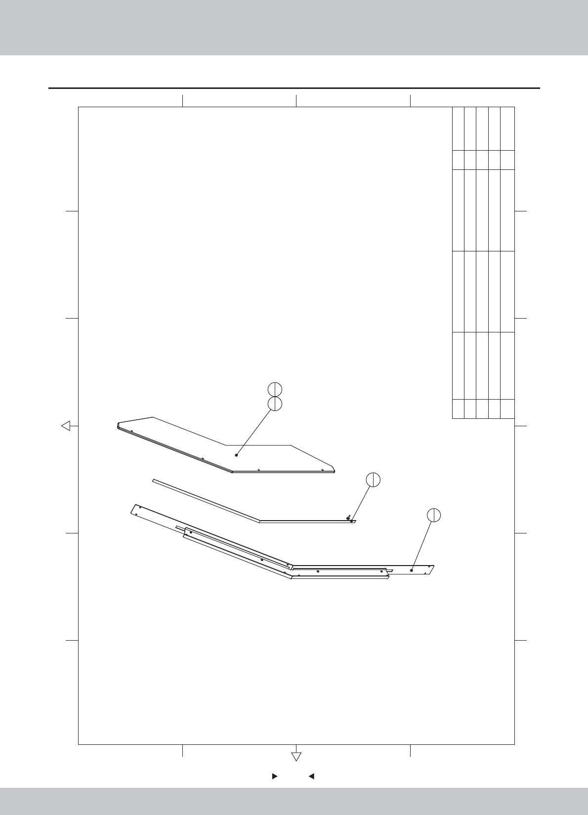
6.10 Left side light assembly
82
82
12 6
43 5
365
421
A
B
C
D
C
D
B
A
2
1
3
1
1
1
4
4
4M4*12(Black)
4
3
Flexible Strip Light
5050RGB60 80cm
1
2
Sides L Acrylic
PMMA-8.0T
1
1 SRF-0900A01
Lamp fixed iron L
SPCC-1.2T
1
1.1.WA10E00450
1.7.WA10E00050
1.4.ZM900900
1.6.LS841021
SRF-P0003
No. Draw No. Name Material/Spec.
Product Code
Qty.
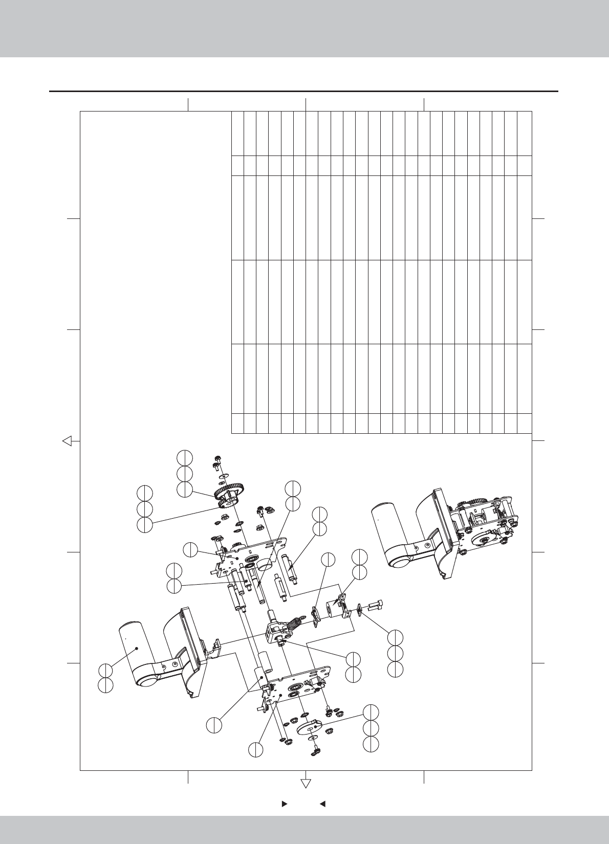
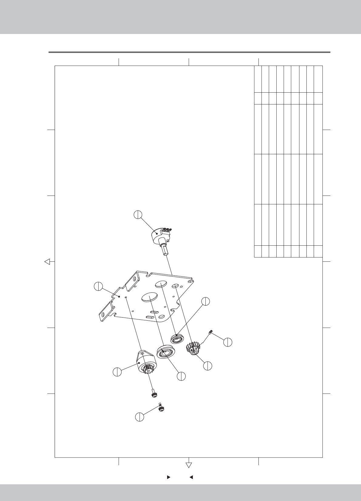
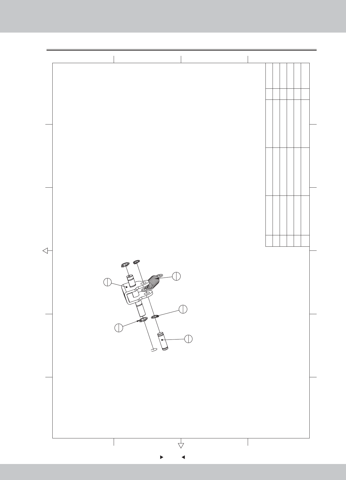
6.11 Push rod assembly
83
83
1
1
3
1
2
1
4
15
1
6
1
7
3
8
1
9
4
10
1
11
2
12
1
13
1
14
1
21
4
16
219
4
15
6
15
2
20
818
119
1
17
119
1
18
1
19
1
23
2
22
2
23 M6(Black) 2
22 M5*16(Black) 2
21 M5*12(Black) 4
20 M5(Color) 8
19 M4*8(Black) 7
18 Φ4*Φ16*1.0(Black) 2
17 Φ4*Φ10*1.0(Black) 1
16 GB/T 894.1-1986 10 2
15
E-type buckle
M6 8
14 SRF-1000C04 Cam white POM 1
13 SRF-1000C03 duplex gear white POM 1
12 SRF-1000C02 master gear white POM 1
11 SRF-1000C01 Limit Stop Collar 2
10 SRF-1000A04 Leaf spring cover SPCC-2.0T 1
9 SRF-1000A03 Positioning axes 45 4
8 SRF-1000A02 Intermediate shaft 45 1
7 SRF-1000A01 Spring shaft A 45 3
6 SRF-1006000 Suction block ASSY 1
5 SRF-1005000 Electromagnet ASSY 1
4 SRF-1004000 Rive shaft ASSY 1
3 SRF-1003000 RIGHT side plate ASSY 1
2 SRF-1002000 LEFT side plate ASSY 1
1 SRF-1001000 Handle ASSY 1
1.1.WA10E00460
1.1.WA10E00470
1.1.WA10E00480
1.1.WA10E00490
1.8.WA10E060
1.8.WA10E070
1.8.WA10E080
1.8.WA10E090
1.6.DQ106011
1.6.DQ336060
1.6.DP104011
1.6.DP104041
1.6.LS840021
1.6.LM205013
1.6.LS851021
1.6.LSF51031
1.6.DP206011
12 6
43 5
365
421
A
B
C
D
C
D
B
A
No. Draw No. Name Material/Spec.
Product Code
Qty.
84
84
6.11.1 Handle assembly
M4(CR) 4
8M3*8(Black) 4
7 SRF-1001C06
The push rod shell
Black ABS 1
6 SRF-1001C05
decoration cover board
Black ABS 1
5 SRF-1001C04
handle lamp cap
Blue PC 1
4 SRF-1001C03
handle decoration
Blue ABS+PC 1
3 SRF-1001C02
handle side cap
Black ABS 1
2 SRF-1001C01
handle with plastic around
1
1 SRF-1001A01
Mounting plate
SPCC-2.0T 1
1.1.WA10E00500
1.8.WA10E100
1.8.WA10E110
1.8.WA10E120
1.8.WA10E130
1.8.WA10E140
1.8.WA10E150
1.6.LS830021
1.6.LM104012
1.6.LSF41022
12 6
43 5
365
421
A
B
C
D
C
D
B
A
1
1
7
1
2
1
4
1
6
1
3
1
5
1
8
2
9
4
10
4
8
2
10 M4*12(CR) 4
9
No. Draw No. Name Material/Spec. Product CodeQty.
85
85
6.11.2 Left side plate assembly
1
1
4
1
2
1
8
1
7
2
3
1
6
1
5
1
8M3*6(Black) 1
7M3*8(Black) 2
6
Bearing
F618-8 1
5
Bearing
F61900 1
4
Potentiometer
B-5KΩ 270 1
3
Resistance round
LF-38A(500-600)
1
2 SRF-1002C01
Potentiometer gear
white POM 1
1 SRF-1002A01
Side plate L
SPCC-2.0T 1
1.1.WA10E00510
1.8.WA10E160
1.4.ZL010010
1.4.VR150220#
1.4.ZC619000
1.4.ZC619001
1.6.LS830021
1.6.LST300211
12 6
43 5
365
421
A
B
C
D
C
D
B
A
No. Draw No. Name Material/Spec. Product Code
Qty.
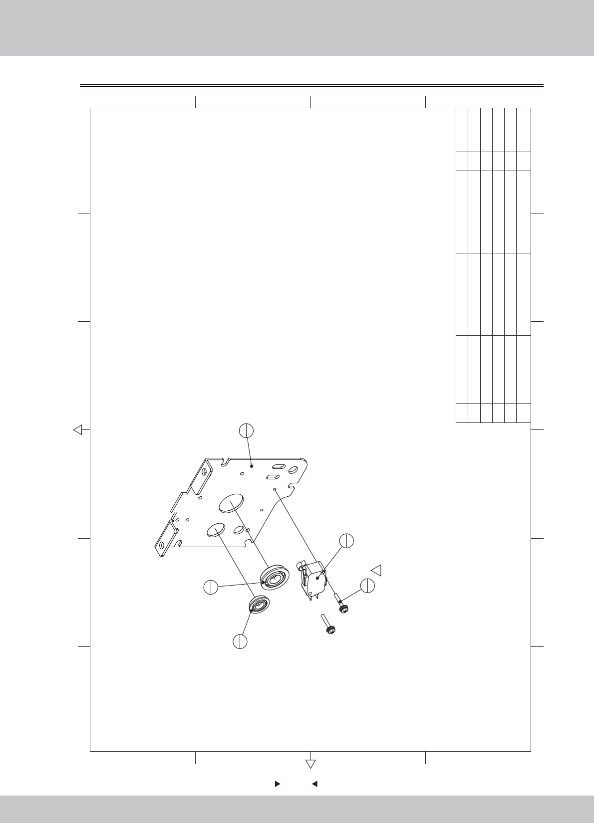
6.11.3 Right side plate assembly
86
86
2
1
3
1
4
1
5
21
5 M3*16 2
4
Bearing
F61900 1
3
Bearing
F618-8 1
2
Micro Switch
3P KW3A 1
1 SRF-1003A01
Side plate R
SPCC-2.0T 1
1.1.WA10E00520
1.4.SW303010
1.4.ZC619001
1.4.ZC619000
12 6
43 5
365
421
A
B
C
D
C
D
B
A
1
1
No. Draw No. Name Material/Spec. Product CodeQty.
6.11.4 Drive shaft assembly
87
87
2
1
4
2
5
2
3
1
1
1
5M6(Black) 2
4GB/T 894.1-1986 10 2
3 SRF-1004A04 Tension springs 1
2 SRF-1004A03
Spring shaft B
45 1
1 SRF-1004A01 Rotation webs plate 1 1.1.WA10E00530
1.1.WA10E00540
1.1.WA10E00550
1.6.DQ336060
1.6.DQ106011
12 6
43 5
365
421
A
B
C
D
C
D
B
A
No. Draw No. Name Material/Spec. Product CodeQty.
88
88
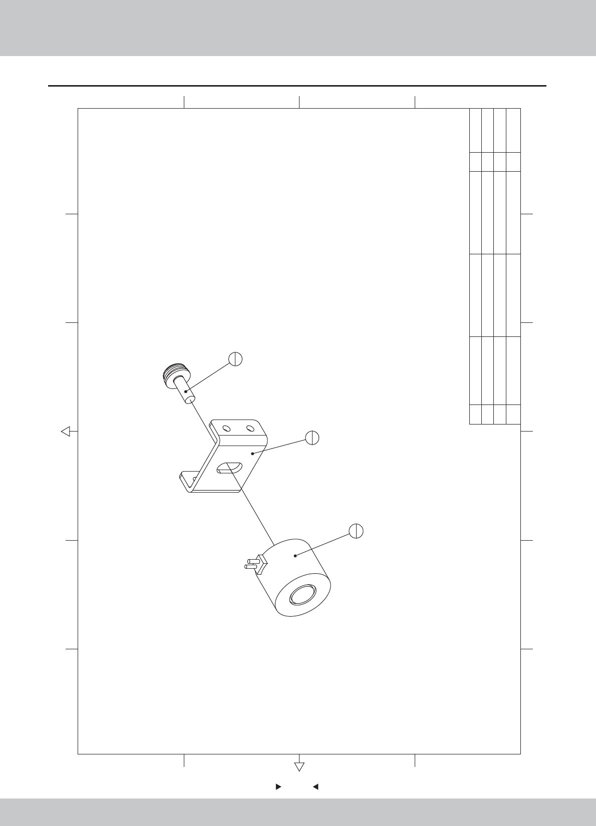
6.11.5 Electromagnet assembly
2
1
1
1
3
1
3M5*12(Black) 1
2
Electromagnet
H2520 DC12V/2.8W 1
1 SRF-1005A01
Electromagnet fixed plate
SPCC-2.0T 1
1.1.WA10E00560
1.4.CT010030
1.6.LS851021
12 6
43 5
365
421
A
B
C
D
C
D
B
A
No. Draw No. Name Material/Spec.
Product Code
Qty.
89
89
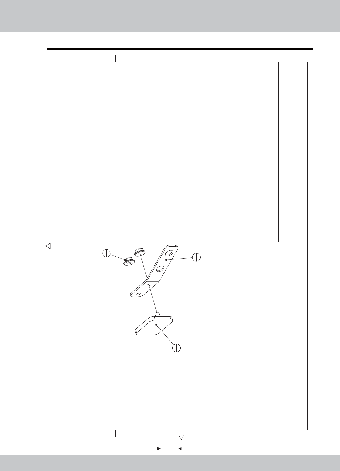
6.11.6 Suction block assembly
1
1
2
1
3
2
3M3(Color) 2
2 SRF-1006A02 Connection block SPCC-3.0T 1
1 SRF-1006A01 Leaf spring SUS304-1.2T 1 1.1.WA10E00570
1.1.WA10E00580
1.6.LM203013
12 6
43 5
365
421
A
B
C
D
C
D
B
A
No. Draw No. Name Material/Spec.
Product Code
Qty.
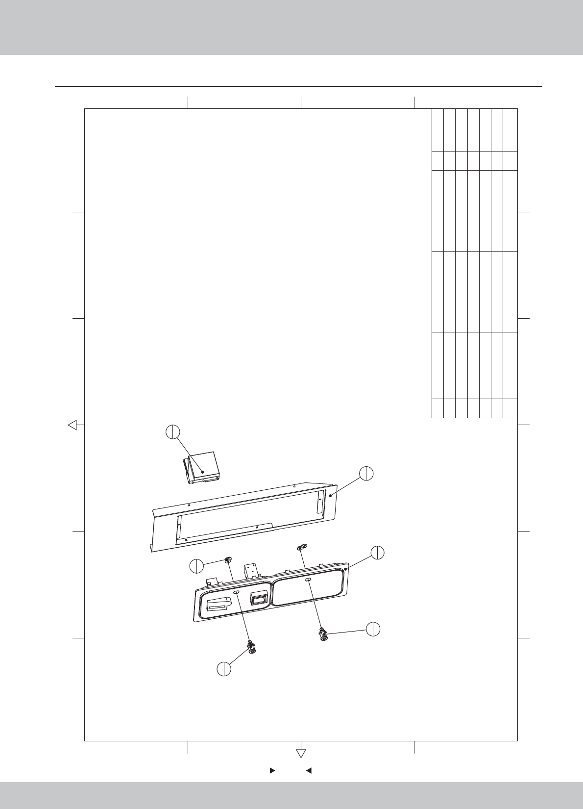
6.12 Coin door assembly
90
90
12 6
43 5
365
421
A
B
C
D
C
D
B
A
3
1
5
1
1
1
6
1
2
2
4
1
6Electronic coin TW-800Ⅲ 1
5Lock M7-K 1
4LOCK 5555 1
3Coin door body 1
2 SRF-1100A02 Locking plate SPCC-2.0T 2
1 SRF-1100A01 Coin door fixed iron SPCC-1.5T 1
1.1.WA10E00590
1.1.WA10E00600
2.1.AA030010
1.4.SJ120120
1.4.SJ220050
1.4.TB100050
No. Draw No. Name Material/Spec. Product CodeQty.
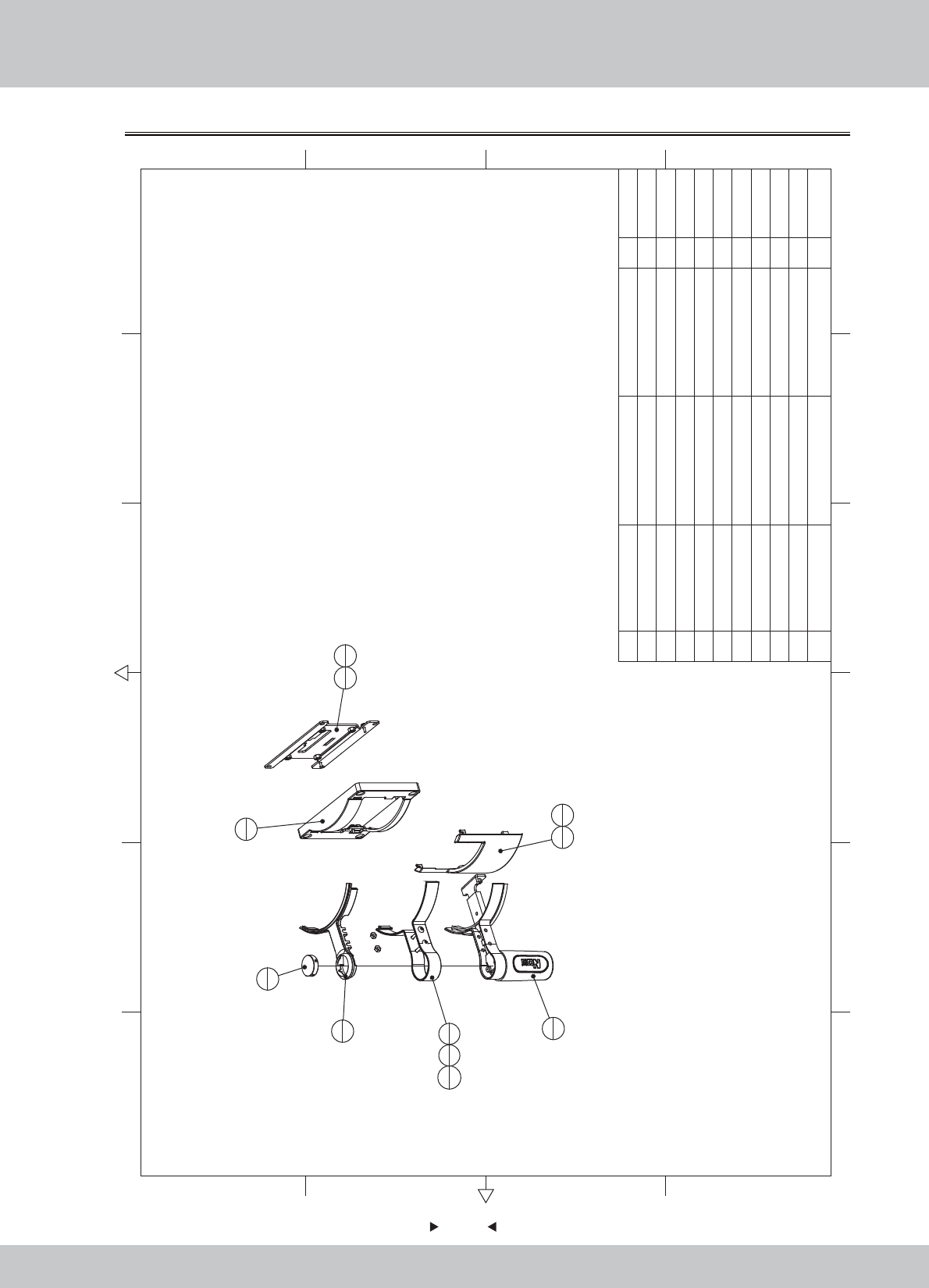
6.13 Stepping cover assembly
91
91
12 6
43 5
365
421
A
B
C
D
C
D
B
A
1
1
2
1
3
1
4
1
5
1
6
2
6
2
6M4*20(Black) 4
5EVA 3*20mm 1
4 SRF-1200A03 Aluminum fixed iron B SPCC-1.2T 1
3 SRF-1200A02 Aluminum fixed iron A SPCC-1.2T 1
2 SRF-1200A01 Pattern aluminum AL 1
1 SRF-1200B01 Steppin plate HDF-18.0T 1
1.2.WA10E00070
1.1.WA10E00610
1.1.WA10E00620
1.1.WA10E00630
1.9.HM020030
1.6.LS242011
No. Draw No. Name Material/Spec. Product Code
Qty.
6.14 Pedal assembly
92
92
1
1
2
13
6
3M4*8(Black) 6
2 sr1-0400a02 Pedal cover SUS304-1.5 1
1 SRF-1300A01 Pedal cover fixed iron SPCC-1.2T 1
1.1.WA10E00640
1.1.WA10A00200
1.6.LS240021
12 6
43 5
365
421
A
B
C
D
C
D
B
A
No. Draw No. Name Material/Spec. Product CodeQty.
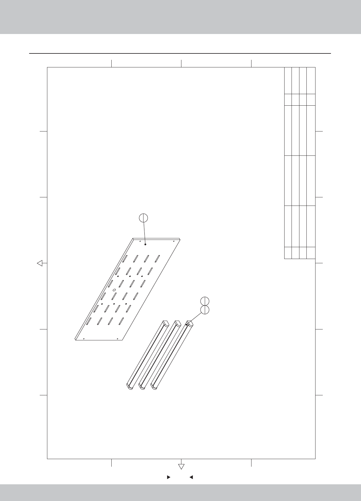
6.15 Upper assembly of back door plate
93
93
1
1
2
33
6
3M4*12(Black) 6
2Fluorescent lamp T8 18W/AC220V 3
1 SRF-1400B01 Back door U HDF-15.0T 1 1.2.WA10E00080
1.4.ZM101810
1.6.LS341021
12 6
43 5
365
421
A
B
C
D
C
D
B
A
No. Draw No. Name Material/Spec. Product CodeQty.
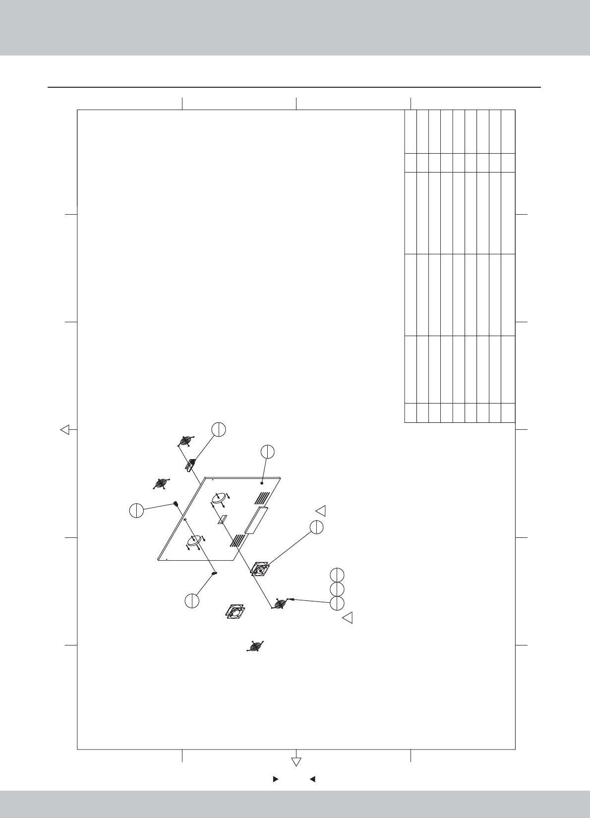
6.16 Intermediate assembly of back door plate
94
94
1
1
5
2
2
1
3
1
4
46
87
8
8
1
1
1
8Plastic buckle hand 1
7M48
6M4*70(CR) 8
5Fan 120*120/AC220V 2
4Fan cover 120*120 4
3Locking plate (001号) 1
2Key 5555锁-K 1
1 SRF-1500B01 Back door M HDF-15.0T 1 1.2.WA10E00090
1.4.SJ120130
1.4.SJ500060
1.4.FS300020
1.4.FS200042
1.6.LS747012
1.6.LM204013
1.8.AA000040
12 6
43 5
365
421
A
B
C
D
C
D
B
A
No. Draw No. Name Material/Spec. Product CodeQty.
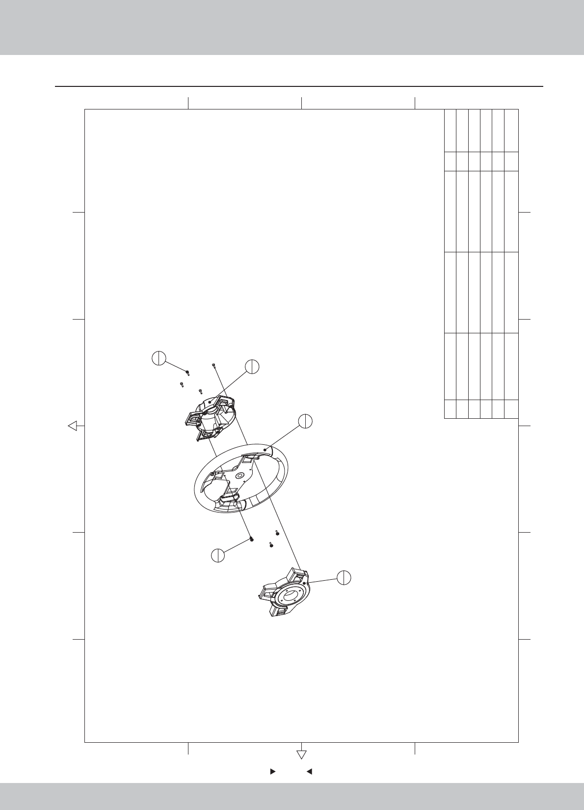
6.17 Steeling wheel assembly
95
95
2
1
1
1
3
1
5
4
4
3
5M4*12(CR) 4
4M4*12(Black) 3
3 SR1-1300C02
The steering wheel cover(bottom)
ABS -2.5 1
2 SR1-1300C01 The steering wheel cover(top) ABS -2.5 1
1 SR1-1300A01 Steering wheel 11.1.WA10A00490
1.8.WA10A070
1.8.WA10A080
1.6.LS841021
1.6.LSF41022
12 6
43 5
365
421
A
B
C
D
C
D
B
A
No. Draw No. Name Material/Spec.
Product Code
Qty.
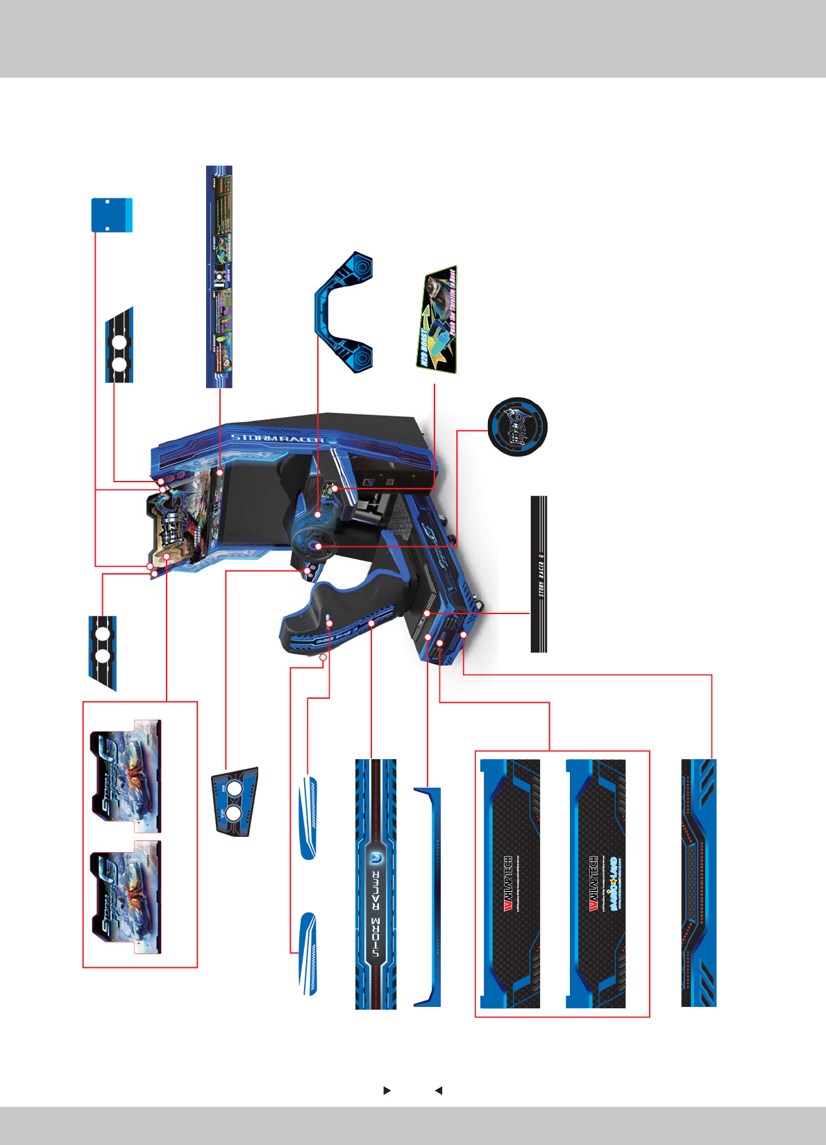
96
96
1/3
7. Printing Pattern
SRFE-P0004E
1.7.WA10F00060
SRF-P0001M
1.7.WA10G00030
SRF-P0001E
1.7.WA10F00030
SRF-P0024
1.7.WA10E00260
SRF-P0023
1.7.WA10E00250
SRF-P0013
1.7.WA10E00150
SRF-P0012E
1.7.WA10F00140
SRF-P0012M
1.7.WA10G00140
SRF-P0036E
1.7.WA10F00380
SRF-P0037E
1.7.WA10F00390
SRF-P0005
1.7.WA10E00070
SRF-P0006
1.7.WA10E00080
SRF-P0007
1.7.WA10E00090
SRF-P0022
1.7.WA10E00240
SRF-P0032
1.7.WA10E00340
SRF-P0030
1.7.WA10E00320
SRF-P0028
1.7.WA10E00300
SRF-P0029
1.7.WA10E00310
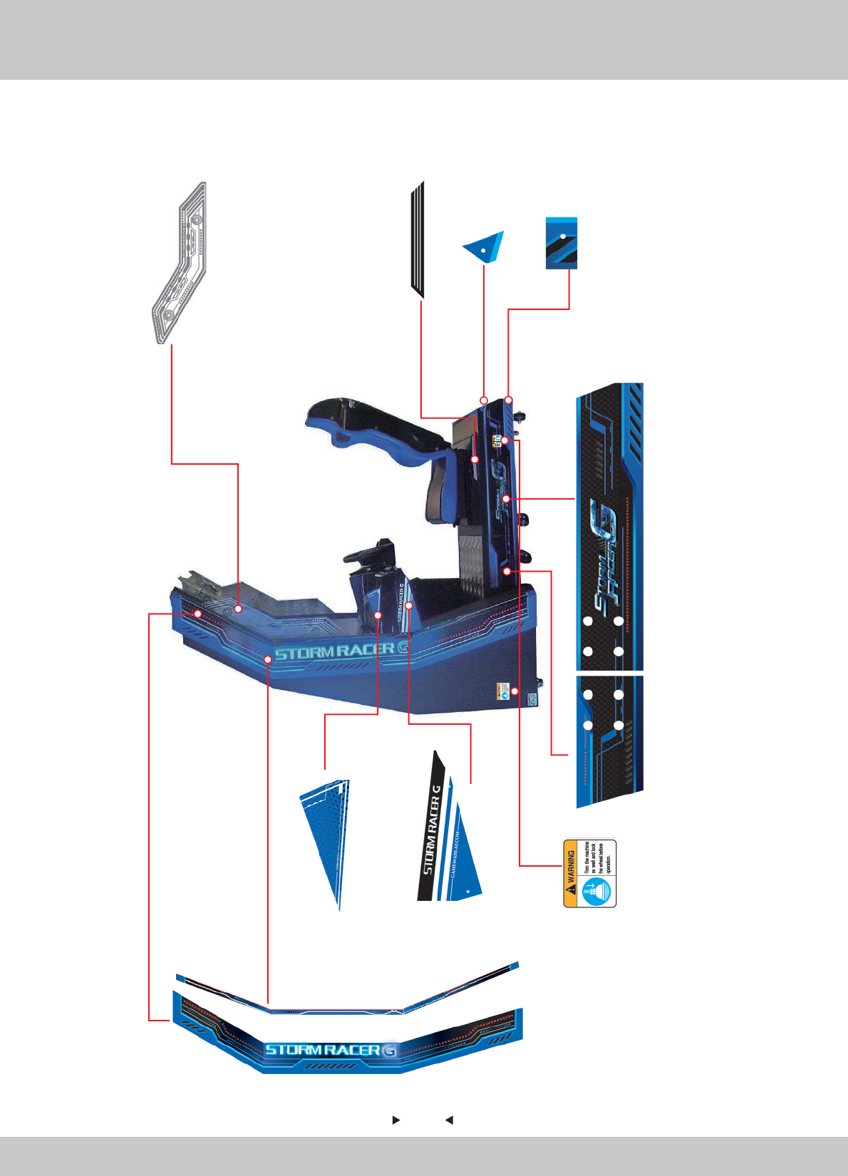
97
97
2/3
SRF-P0031
1.7.WA10E00330
SRF-P0003
1.7.WA10E00050
SRF-P0021
1.7.WA10E00230 1.7.WA10E00210
SRF-P0019
SRF-P0026
1.7.WA10E00280
SRF-P0035
1.7.WA10E00370
SRF-P0010
1.7.WA10E00120
SRF-P0011
1.7.WA10E00130
SRF-P0017
1.7.WA10E00190
1.7.WA10E00170
SRF-P0015
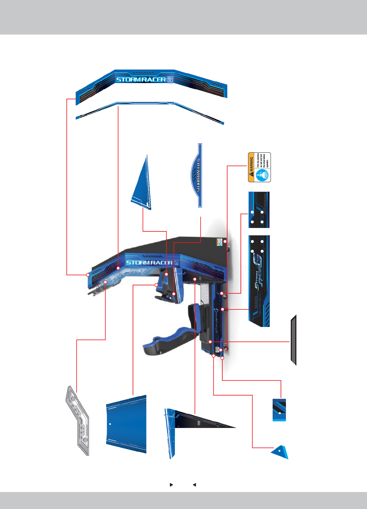
98
98
3/3
SRF-P0002
1.7.WA10E00040
SRF-P0018 SRF-P0020
1.7.WA10E00200 1.7.WA10E00220
SRF-P0016
1.7.WA10E00180
SRF-P0008
1.7.WA10E00100
SRF-P0009
1.7.WA10E00110
SRF-P0014
1.7.WA10E00160
SRF-P0025
SRF-P0033
1.7.WA10E00350
SRF-P0027
1.7.WA10E00290
SRF-P0034
1.7.WA10E00360
SRF-P0038
1.7.WA10E00400
1.7.WA10E00270

99
99
8. Wiring Diagram
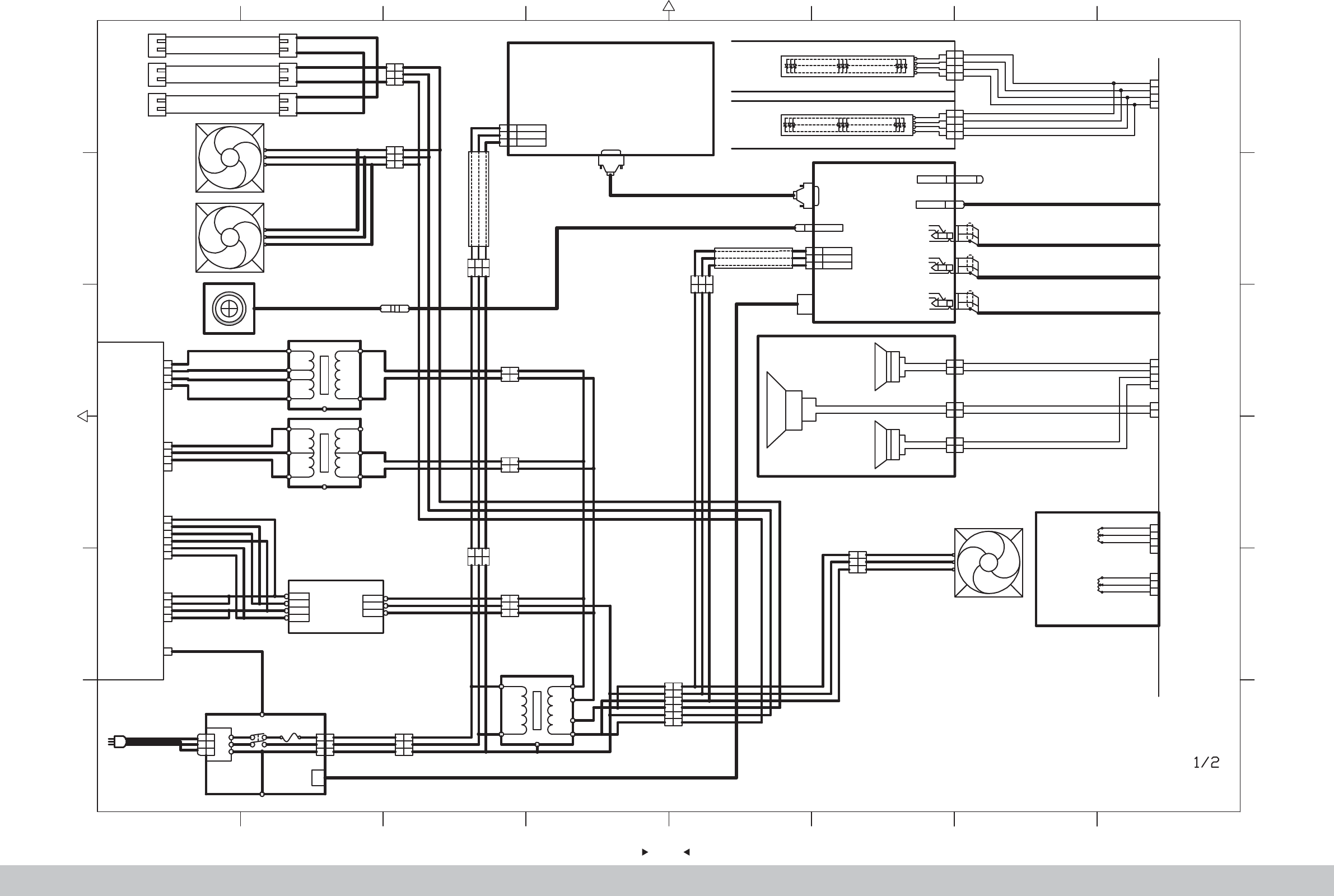
100
100
87654321
2 876543
1
L
N
G
L
N
G
NOISE
LINE LOAD
FIL
L
N
G
YL
PL
GN/YL
1
3
2
GN/YL
1
3
2
Power Line
SW1 FUSE 6A
BN
BU
GN/YL
AC220V
BN BN
BU
K1 VL3P
BU
Internet Connector
GND
R
L
WT
RD
BK
GND
R
L
WT
RD
BK
GND
R
L
WT
RD
BK
Double Audio
Frequency
33.5
Double Audio
Frequency
3 3.5
Double Audio
Frequency
33.5
K57
K61
K59
USB
K52 USB-A
AC110V
EARTH
AC110VRET
L
N
G
L
N
G
K8 3P INRET
GN/YL
WT
GY
F
C
R
PC
T8 18W
Fluorescent lamp
T8 18W
Fluorescent lamp
T8 18W
Fluorescent lamp
1
2
3
1
2
3
Accelerator VR115K2
Brake VR215K2
1
2
3
1
2
3
4
RD
PL
BK
ED
BU
BK
K30
K31
Brake & Accelerator
Speaker
3*5" 84/15W
1
2
1
2
3*5" 84 /15W
1
2
1
2
+
+
GN
BK
BK
BU
BK
BU
K71YL2P
K72
YL2P
+
R
G
B
+
R
G
B
LED L
LED R
4
2
1
3
4
2
1
3
4
2
1
3
4
2
1
3
OG
RD
BU
GN
OG
RD
BU
GN
OG
RD
BU
GN
OG
RD
BU
GN
K47SM4P
K46SM4P
RGB
RGB
USB KEYUSB
56
+
Low-Frequency Oscillator
44 /50W
-
Seat
1
3
2
GN/YL
1
3
2
BN
BU
GN/YL
BN
BU
T1 VL3P
Transformer
350W
AC110V
0V
AC110V
0V
0V
14V
Transformer
250W
AC220V
0V
AC16V
AC16V
0V
FG
FG
S-150-12
12V 150W
EARTH
L
COM
+12V
N
BL
OG
COM
+12V
BL
OG
Power Pack
WT
GY
GN/YL
AC110V
Transformer
1100W
AC220V
0V
AC110V
0V
FG
L
N
G
L
N
G
AC220V
EARTH
AC220VRET
GN/YL
BU
BN
INRET 3P
7879% :% 18;
1
2
3
1
2
3
VL3P K3
BN
GN/YL
BU
BN
BU
GN/YL
1
2
3
1
2
3
VL3P K2
BN
GN/YL
BU
BN
BU
GN/YL
Fan for monitor 1
120*120/AC110V
1
2
3
4
5
6
1
2
3
4
5
6
K6 VL6P
PC Power Line
1
2
3
1
2
3
VL3P K8
WT
GN/YL
GY
WT
GY
GN/YL
1
3
2
GN/YL
1
3
2
WT
GY
GN/YL
WT
GY
K12 VL3P
Camera
1
3
2
GN/YL
1
3
2
WT
GY
GN/YL
WT
GY
K9 VL3P
1
3
2
1
3
2
WT
GY
GN/YL
WT
GY
K13 VL3P
1
2
1
2
K16 VL2P
1
2
1
2
K17 VL2P
AC110V
0V
VIDEO
DVI
DVI
VIDEO
DVI DVI
USB
K50 USB-A
USB
1
2
3
4
K18
1
2
3
4
K21
1
2
3
4
K22
1
2
3
4
5
6
K23
1
2
3
4
37"LED
1
2
1
2
1
2
3
4
1
2
Fan for Transformer
120*120/AC110V
K4
WT
GN/YL
GY
WT
GN/YL
GY
WT
GY
WT
GY
GN/YL
GN/YL
1
3
2
GN/YL
1
3
2
WT
GY
GN/YL
WT
GY
K7 VL3P
VLR-04V
VLP-04V
YLP-06V
YLP-04V
K51
WT
GY
WT
GY
WT
GY
WT
GY
BU
BK
WT
GY
BU
BK
BU
OG
OG
OG
OG
OG
OG
BK
BK
BK
BK
OG
RD
BU
GN
K42
YLP-04V
K73
YLR-04V
GN
BK
GN
BK
BK
BU
K76YL2P
YLP-02V
K75
GN
BK
GN
BK
GN
BK
YLP-04V
YLP-03V
1
K26
VLP-01V
AC< FG
GN/YL
2/2 E8
2/2 E8
2/2 B8
2/2 C8
2/2 A8
2/2 C8
2/2 D8
2/2 D8
2/2 C8
2/2 C8
2/2 B8
2/2 B8
2/2 B8
(F)
(C)
(R)
2/2 B8
Monitor
Fan for monitor 2
120*120/AC110V
Speaker
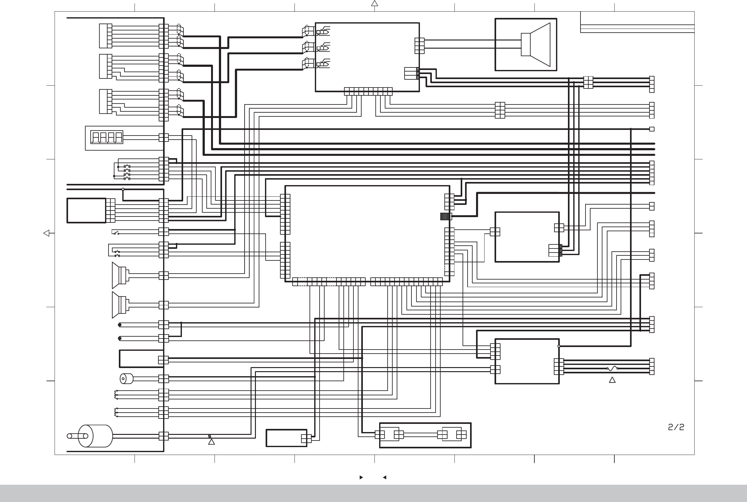
101
101
87654321
2 876543
1
1
2
3
4
5
6
1
2
3
4
5
6
7
8
7
WT
RD
BK
WT
RD
BK
WT
RD
BK
WT
RD
BK
K54
K55
K56
SM6P
SM7P
SM8P
1
2
1
2
1
2
3
4
5
6
1
2
3
4
5
6
GN
GY
BU
PL
WT
BK
GN
BK
K27 YL2P
K24 YL6P
UP
TEST
SERVICE
GN
GY
DOWN
Stopwatch (Coin)
Service Pannel
1
2
3
5
4
6
Volume VR-B10K3
1
2
3
4
5
6
1
2
3
5
4
6
VR-B10K3
1
2
3
5
4
6
VR-B10K3
3
2
1
3
2
1
3
2
1
HIGH
1
2
1
2
1
2
1
2
K29 YL3P
K49 VL2P
K34 YL2P
1
2
1
2
+12V
PWM
K39XH2P
Boost Controller
GND
RL
WT
RD
BK
GND
RL
GND
RL
WT
RD
BK
WT
RD
BK
Double Audio
Frequency
43.5
Double Audio
Frequency
43.5
Double Audio
Frequency
43.5
K58
K62
K60
INRET
AC16V
0V
AC16V
1
2
3
4
1
2
3
4
K66
VH4P
M-
M+
BU
BK
BU
F
C
R
Amplifier Board
BN
BK
1
2
3
4
5
6
1
2
3
4
5
6
1
2
3
4
5
6
7
8
7
WT
RD
BK
WT
RD
BK
WT
RD
BK
WT
RD
BK
WT
RD
BK
WT
RD
BK
BN
-+
BK
Bass
1
2
3
4
K21
VLR-04V
BU
BK
BU
1
2
3
4
1
2
3
4
K33 YL4P
START KEY
VIEW KEY
1
2
1
2
K38 YL2P
1
2
1
2
K36 YL2P
LED1 BU2START
LED1RD2
VIEW
Control Panels
1
2
1
2
+
K68 YL2P
Speaker
4" 43/25W
1
2
1
2
+
K69 YL2P
1
2
3
4
Coin Selector
5
6
1
2
3
4
5
6
TW-800III
K28XHP-6
Steering wheel VR1 5K2
1
2
3
4
5
6
1
2
3
4
5
6
K25 YL6P
FG
5
6
7
5
6
7
8
9
10
8
9
10
J1
XHP-10
J2
9
8
7
6
5
4
3
9
8
7
6
5
4
3
2
1
2
1
XHP-9
3
1
2
6
4
5
K23
YLR-06V
1
2
3
4
1
2
3
4
12V
GND
J11VHR-4N
Electromagnet
H25201DC12V5 12W2
1
2
1
2
K37 YL2P
1
2
3
4
1
2
3
4
GND
IO Board
3
2
1
3
2
1
K32 YL3P
3
2
1
M+M-
Motor
15 6 7 815 16 17 18 19 20
1567 8 15 16 17 18 19 20
5557-20R
J10
12345 6 78 9 10 11 12 13 14 15
1 2 3 45 6 7 8 9 10 11 12 13 14 15
XHP-15
J5
USB-B
K53
1
2
3
4
5
6
7
1
2
3
4
5
6
7
8
9
8
9
16
16
J8
5557-16R
1
2
3
4
K22
YLR-04V
OG
OG
OG
OG
1
2
1
2
K74VHR-2N
1
2
1
2
K43 XHP-2
GND
PWM
INRET
AC16V
0V
AC16V
BU
BK
BU
1
2
3
4
1
2
3
4
PWM
LEFT
RIGHT
+12V
XHP-4K41
4
3
2
1
4
3
2
1
0V
0V
AC110V
AC14V
K19
VHR-4N
1
2
1
2
K48
VHR-2N
+
-
1
2
1
2
+12V
PWM
K35XH2P
Camera LED
1
2
1
2
K40 XH2P K44 XH2P
1
2
1
2
1
2
1
2
K45 XH2P
1
2
1
2
GN
OG
GN
OG
LED
1
2
3
4
K42
YLR-04V
1
2
3
4
K18
VLP-04V
1
3
2
1
3
2
K20 VL3P
1
2
YLR-02V
K75
GN
BK
GN
BK
1
2
3
4
K73
YLP-04V
GN
BK
BK
BU
1
2
3
4
GN
BK
BK
BU
1
2
3
4
GN
BK
BK
BU
YL4PK70
1
2
3
1
2
3
4
RD
PL
BK
RD
BU
BK
K30
K31
YLR-04V
YLR-03V
1 2 3 4 5 6 7 8 9 10
1 2 3 4 5678910
FL FR FR C C RL RL RR RR
VH10P
-FL
+ - +-+-+-+
K67
1
K26
VLR-01VF
FG
COIN
DOWN
UP
TEST
SERVICE
+12V
BN
GN
BU
PL
WT
OG
BNBN
GN
BU
PL
WT
BK
BK
BN
GN/YLGN/YL
GN/YL
GN
GY
OG
BK
GN
GY
OG
BK
GN
GY
OG
BK
OG
BK
BK
BN
START KEY
RD
VIEW KEY
BU
BN
RD
BN
RD
BK
BK
BK
BK
BUBU
BK
BK
OG
BK
BK
OG
BK
BK
BK RDWT BK RDBU BK RDPL BK RDGN
GND
Boost Controller VR
3.3V
GND
Brake VR
3.3V
GND
Accelerator VR
3.3V
GND
Steering wheel VR
3.3V
BK
WT
RD
BK
WT
RD
BK
GN
RD
BK
GN
RD
WT BN GN PL
BU WT
GN
BN
WT
GN
LT
Dynamic panels1 R2
Camera LED
VIEW LED
Dynamic panels1 L2
Electromagnet
START LED
LED for control Panel
LED
WTBN
WTGN
PK
OG
BN
GNGN
BUBU
PLPL
WT
LTGN
OG
OG
OG
OGOG
OG
OG
OGOG
BKWT BKWT
BN
BN
RD
GN
BU
PK
GND
R
G
B
PWM
PWM
RD
GN
BU
OG
K63 XHP-6
K64 XHP-6
K65 XHP-6
WT
RD
BK
WT
RD
BK
WT
RD
BK
WT
RD
BK
WT
RD
BK
WT
RD
BK
WT
RD
BK
WT
RD
BK
BK BN BK RD BK GN BK BU
BK
BN
BK
BN
BK
RD
BK
RD
RD
BK
RD
BK
RD
BK
1/2 C1
1/2 E1
1/2 E1
1/2 D1
1/2 D1
1/2 D8
1/2 E8
1/2 A8
1/2 C8
1/2 B8
1/2 B8
1/2 B8
1/2 C8
(F)
(C)
(R)
1/2 C8
BU
BK
BU
BU
BK
BU
Vibrator Horn
Driver Board
BU
BK
WT
GY
BU
BK
WT
GY
GND
SIGNAL
FUSE 5A
1
Piezoresistor 391KD10
1
Volume
Volume
4" 43 /25W
Speaker
Light board
for control
panels
DRIVE
BOARD
Boost cont
-roller
HIGH
Boost Controller
VR1 5K2 B-5K3
2706
Honorable customer !
Thank you for purchasing our product !
For your benefits, if you find any fault during the operation of the
product, please use a technician who obtains a certificate related
to mechanical engineering, electrical engineering or who engages
in routine maintenance, repair and management of amusement
machine to check the machine and inform us the fault in a timely
manner. Our company will take corresponding measures to assist
you to solve the problem promptly.
NOTICE
NOTICE
:Do not dismount or replace any part of the machine without
our technician’s permission, or you will solely undertake the
consequence !
Please pay attention to our contact information as follow:
GuangZhou Wahlap Technology Limited
9. After-sales Service
102
102

The specifications and operation instructions in this Manual are subject
to change without notice for reasons such as performance.
Ver.3.00
